A comparison of the impact behavior of RC and CFT …€¦ · A comparison of the impact behavior...
11
A comparison of the impact behavior of RC and CFT circular columns under lateral impact loading *C. Demartino 1) , J.J. Xu 2) , J.G. Wu 3) , X.Y Wang 4) , J.C. Ding 5) , and Y. Xiao 6) 1,2,5,6) College of Civil Engineering, Nanjing Tech University, Nanjing 211816, China 3,4) College of Civil Engineering, Hunan University, Changsha, Hunan 410082, China 1)* [email protected] ABSTRACT This study presents a set of new test data for circular Reinforced Concrete (RC) and Concrete Filled steel Tube (CFT) columns under lateral impact loading. A total of four specimens were tested in the new horizontal impact facility in the Collision Laboratory of the Nanjing Tech University in China. The models were scaled to 1/3 of the prototype size in order to place them in the facility and the load was applied in the typical position of a vehicle (truck) impact. RC columns exhibited a brittle shear-type damage, characterized by one main diagonal crack originating from the base of the column to the impact point, revealing the high vulnerability of these structural elements. CFT column exhibited a similar damage pattern of the concrete inside the steel tube and instability phenomena in the steel tube. CFT columns exhibited a better response under impact loads due to the confinement effect of the steel tube. 1. INTRODUCTION Circular Reinforced concrete (RC) and Concrete Filled steel Tube (CFT) columns are widely used for the realization of bridge piers. Moreover, they are also commonly employed are widely used in the primary lateral resistance systems of both braced and unbraced building structures. Such structures are exposed to the vehicular impact hazard. In many cases, the vehicle collisions produced catastrophic consequences, with significant property loss and people injuries or even casualties. Previous research available in literature has explored the dynamic response of RC and CFT column under impact loads using both numerical and experimental tests. Generally, experimental studies do not consider the deformability and damage of the colliding vehicles, modeling them as a rigid body. This can be an upper-bound of the possible damage to the column for a given initial kinetic energy. 1-2) Post-Doc 3-5) Master student 6) Professor
Transcript of A comparison of the impact behavior of RC and CFT …€¦ · A comparison of the impact behavior...

A comparison of the impact behavior of RC and CFT circular columns
under lateral impact loading
*C. Demartino1), J.J. Xu2), J.G. Wu3), X.Y Wang4), J.C. Ding5), and Y. Xiao6)
1,2,5,6) College of Civil Engineering, Nanjing Tech University, Nanjing 211816, China 3,4) College of Civil Engineering, Hunan University, Changsha, Hunan 410082, China
ABSTRACT
This study presents a set of new test data for circular Reinforced Concrete (RC) and Concrete Filled steel Tube (CFT) columns under lateral impact loading. A total of four specimens were tested in the new horizontal impact facility in the Collision Laboratory of the Nanjing Tech University in China. The models were scaled to 1/3 of the prototype size in order to place them in the facility and the load was applied in the typical position of a vehicle (truck) impact. RC columns exhibited a brittle shear-type damage, characterized by one main diagonal crack originating from the base of the column to the impact point, revealing the high vulnerability of these structural elements. CFT column exhibited a similar damage pattern of the concrete inside the steel tube and instability phenomena in the steel tube. CFT columns exhibited a better response under impact loads due to the confinement effect of the steel tube. 1. INTRODUCTION
Circular Reinforced concrete (RC) and Concrete Filled steel Tube (CFT) columns are widely used for the realization of bridge piers. Moreover, they are also commonly employed are widely used in the primary lateral resistance systems of both braced and unbraced building structures. Such structures are exposed to the vehicular impact hazard. In many cases, the vehicle collisions produced catastrophic consequences, with significant property loss and people injuries or even casualties.
Previous research available in literature has explored the dynamic response of RC and CFT column under impact loads using both numerical and experimental tests. Generally, experimental studies do not consider the deformability and damage of the colliding vehicles, modeling them as a rigid body. This can be an upper-bound of the possible damage to the column for a given initial kinetic energy.
1-2) Post-Doc 3-5) Master student 6) Professor

Considering experimental results, it should be highlighted that the majority of the available tests was performed on horizontal elements featuring beam characteristics using falling mass facilities. This approach was used by different authors on RC columns by applying the impact load at the midspan (e.g., Feyerabend, 1988, Remennikov, 2006, Cotsovos, 2008, Saatci, 2009, Magnusson 2010, Isaac, 2017). Moreover, this approach was also used on CFT columns by different authors (e.g., Bambach, 2008, Remennikov, 2010, Deng, 2011, Wang, 2013, Han, 2014, Wang, 2015, Yousuf, 2013, Shakir, 2016, Yang, 2015). All the studies demonstrated that impulsive loads propagate differently from quasi-static loads leading to different damage patterns.
Another common approach is the use of mass pendulum system in which a mass is suspended from a pivot so that it can swing impacting the column (Loedolff, 1989, Silva, 2009, Zhang, 2016). In particular, Zhang (2016) compared the resistance against impact between precast segmental columns and monolithic RC columns. The main limitation of these approaches is that they cannot adequately reproduce the rebound conditions due to the gravity influence.
However, a limited knowledge of the dynamic response of both RC and CFT circular columns under impact loads is available. Moreover, limited tests were performed considering the real orientation of the column, i.e. vertical, and the impact direction, i.e. horizontal. In this context, a new facility for the testing of vertical elements such as bridge piers was realized in the Collision Laboratory of the Nanjing Tech University in China. Although different tests were performed on the two structural types, the comparison of the impact behavior of RC and CFT circular columns under lateral impact loading is not available in the literature.
In this paper, the comparison of the impact behavior of RC and CFT circular columns under lateral impact loading will be analyzed. Four impact tests on RC and CFT columns were conducted. The models were scaled to 1/3 of the prototype size in order to place them in the facility and the load was applied in the typical position of a vehicle (truck) impact. During the impact tests, impact force, reaction force and displacements were measured. A high-speed camera was installed to record the impact and damage dynamics. 2. TEST PROGRAM
Four cantilever specimens, including two RC columns and two CFT columns, were tested using the horizontal collision facility in the Collision Laboratory of Nanjing Tech University. Details of the horizontal collision facility, of the specimens and of the experimental procedure, are given in the following.
The facility is shown in Figure 1 and mainly consists of a test truck, a dropping mass and a tested specimen (i.e. a column). The test truck is made of a four-wheeled test truck moving on a horizontal rail and is equipped with an instrumented hammer (front size: 580 mm long and 200 mm wide). The test truck is accelerated by an external drive mechanism based on a drop weight. The calculation of the impact velocity is done by applying the principle of conservation of energy:
2
1 2 1 20.5 m m v m gh m gh
(1)

where m1 and m2 are the weight of the test truck and of the drop hammer, respectively; v is the impact speed of the vehicle; μ is the friction coefficient calibrated to be around 0.11; h is the initial height of the drop hammer. The maximum height of the drop mass is 20 m and the maximum mass is 1200 kg. The minimum weight of the test truck is 1580 kg.
After the installation of the column specimen, the drop weight was positioned at the calculated height (Eq. 1) to obtain the target velocity and the truck located at a certain distance from the specimen, in order to have the steel wire in tension. During the tests, the drop weight was suddenly released, provoking test truck acceleration and subsequent impact. During the impact tests, impact force, reaction force and displacements were measured. At the end of the tests, photos of the final damage were taken from different points of view.
Figure 1 shows the horizontal collision facility and the location of the sensors. Six linear potentiometer displacement sensors were mounted along the rear side of the column specimen with a spacing of 200 mm starting from the bottom. Moreover, a high-speed camera (SONY NEX-FS700R) was installed to record the impact and damage dynamics with a frame rate of 400 fps.
Fig. 1 Horizontal collision facility: sketch of the facility and of the column specimen
Figure 2 shows the schematic of the specimens. The models were scaled to 1/3 of the prototype size in order to place them in the facility and the load was applied in the typical position of a vehicle (truck) impact. The height of the instrumented hammer center with respect to the concrete foundation is 400 mm. Each specimen consists of a foundation made by a concrete footing (l x w x h= 900 mm x 900 mm x 500 mm) and of a circular cross-section column.
The RC column specimens have the following configuration of the longitudinal reinforcement: 16ϕ8 bars evenly distributed in a circular layer at 26 mm from the external perimeter. The longitudinal reinforcement ratio is about ρl=0.9%. The closed
hoops (ϕ6) have a spacing of with 100 mm leading to a volumetric transverse reinforcement ratio of 0.3%. The full height of the column is 1700 mm (Figure 2).
The CFT column specimens have the same steel thickness equal to 3.75 mm with a ratio of the thickness to the diameter equal to 1.25%. The base of the steel tube is connected with a stiffener buried into the concrete foundation. The steel tube is made of Q235 low carbon steel plate welded straightly. The full height of the column is 1500 mm (Figure 2), slightly shorter than the RC ones.
The compressive strength of the concrete was evaluated by testing different standard cubes with a length of 150 mm leading to an average value of around 40 MPa.
Fig. 2 Schematic and photo of the RC (left) and CFT (right) column specimens. The initial velocity of the test truck was varied with the aim to define the effects
on the mechanical response. In particular, the RC columns were tested at 3 (RC2) and

4.5 m/s (RC1), while the CFT columns at 6 (CFT2) and 7.5 m/s (CFT1). It should be highlighted that the different values of the impact velocity chosen for the RC and CFT columns are related to the different vulnerability of the two structural elements (this will be shown in the following). The performed tests are summarized in Table 1.
Table 1. Test program
Column type Test Tag Boundary condition Impact velocity Mass Kinetic energy
- - - m/s kg kJ
Reinforced concrete RC1 Cantilever 4.5 1580 16
Reinforced concrete RC2 Cantilever 3 1580 7.1
Concrete filled steel tube CFT1 Cantilever 7.5 1580 44.4
Concrete filled steel tube CFT2 Cantilever 6 1580 28.4
3. RESULTS 4.1 Transient response
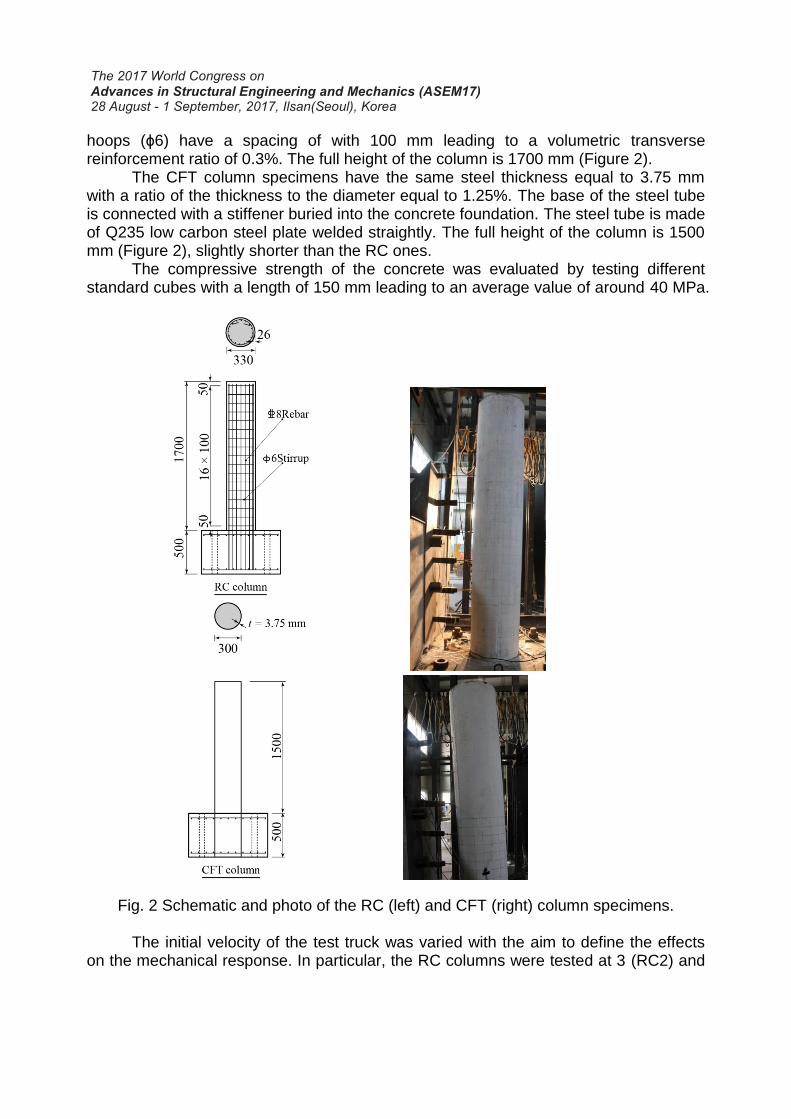
Figures 3 and 4 depict the impact force as a function of the time for the RC and CFT tests, respectively. As expected, the peak value of the impact force is proportional to the value of the initial kinetic energy (see Table 1).
For the RC tests, the time history of the impact force can be divided into two phases (Figure 3). In the first phase, the impact force sharply increases leading to large values of the jerk (i.e. the time rate of change of the acceleration). The first phase is defined from the zero of time to the end of the first peak when the derivative of the decreasing part starts to increase. This sudden increase occurs to obtain deceleration of the test truck and local acceleration of the RC column, to make them acquire a common velocity and move together. A large peak force develops as the RC column is initially at rest. The duration of the first phase is almost the same in all the tests, i.e. t=2.5 ms, and the peak of the impact force is located at about t=1.5 ms. In the second phase, after the first peak, the impact force attenuates gradually to zero. In this phase, the RC column and vehicle acquired a common velocity. This phase finishes when the impact force goes to zero. The reduction of the force is proportional to the damage and subsequent loss of stiffness of the RC column. Only in the RC2 test, it was observed an increase of the impact force up to 50 kN in the range from t=45 ms to t=60 ms. This second increase in the impact force is generated by a second impact that occurs after the test truck rebound and during the elastic recovery of the RC column. This second impact was also confirmed in the frames recorded by the high-speed camera.
RC1 RC2
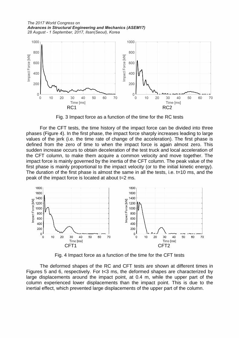
Fig. 3 Impact force as a function of the time for the RC tests For the CFT tests, the time history of the impact force can be divided into three
phases (Figure 4). In the first phase, the impact force sharply increases leading to large values of the jerk (i.e. the time rate of change of the acceleration). The first phase is defined from the zero of time to when the impact force is again almost zero. This sudden increase occurs to obtain deceleration of the test truck and local acceleration of the CFT column, to make them acquire a common velocity and move together. The impact force is mainly governed by the inertia of the CFT column. The peak value of the first phase is mainly proportional to the impact velocity (or to the initial kinetic energy). The duration of the first phase is almost the same in all the tests, i.e. t=10 ms, and the peak of the impact force is located at about t=2 ms.
CFT1 CFT2
Fig. 4 Impact force as a function of the time for the CFT tests The deformed shapes of the RC and CFT tests are shown at different times in
Figures 5 and 6, respectively. For t<3 ms, the deformed shapes are characterized by large displacements around the impact point, at 0.4 m, while the upper part of the column experienced lower displacements than the impact point. This is due to the inertial effect, which prevented large displacements of the upper part of the column.

RC1 RC2
Fig. 5 Column lateral displacements at different times (in ms) for the RC tests For t>3 ms, noticeable differences in the deformed shapes were observed for the
different tests. For the test RC1, large displacements in the lower part of the column were observed; these are related to high values of the drift. Large values of the drift are related to strong shear damage as it will be shown in Section 4.2. In the test RC2, lower values of the drift were observed in the lower part of the column and a corresponding lower damage in the base of the column was observed (Section 4.2). In the CFT1 test (Figure 6), similar displacements of RC1 were observed in the lower part of the column. Lower values of the displacements were observed in test CFT2 because of the lower initial kinetic energy.
CFT1 CFT2
Fig. 6 Column lateral displacements at different times (in ms) for the CFT tests The development of the damage for different times (from t=5 ms to 40 ms) is
shown in Figure 7. In all the frames, it is possible to recognize the nose of the hammer in the lower left part and the column almost in the center.
5 ms 10 ms 20 ms 30 ms 40 ms 5 ms 10 ms 20 ms 30 ms 40 ms

RC1 RC2
5 ms 10 ms 20 ms 30 ms 40 ms 5 ms 10 ms 20 ms 30 ms 40 ms
CFT1 CFT2
Fig. 7 Development of the damage with the time for the four tests
In the RC tests, it was observed one main diagonal crack, with approximately 45° failure surface developing from the rear parts of the base of the column to the impact point. Moreover, tiny cracks in the rear side of the RC column were detected in the bottom half. These are similar to those that can be observed on a simply supported beam loaded by a midspan force, where flexural cracks commonly develop near the force application point, and diagonal shear cracks normally develop close to the supports.
In the CFT tests, it can be observed that the damage mainly occurs in the base part of the CFT column confirming the results coming from the displacement transducers (Figure 6). It can be seen that between at t=20 ms the hammer is detached from the surface of the column while at t=10 ms and 30 ms is attached to the surface confirming the second increase in the impact force previously described (Figure 4).
Comparing RC and CFT columns, it can be observed the larger damage experienced by RC columns. This is more evident considering that the diameter of the RC columns is larger (Figure 2) and that the initial kinetic energy, or impact velocity, is lower (Table 1) in RC tests compared with CFT tests. 4.2 Final damage
Figures 8 and 9 shows the post-impact damage of the RC and CFT columns,
respectively. In the RC tests, the post-impact condition reveals a brittle shear-type damage characterized by one main diagonal crack starting from the base of the column to the impact point. Moreover, some flexural cracks were found in the bottom frontal part and in the rear part, behind the impact point; these are typically located in the

locations of the hoops. These flexural cracks in the rear part indicate the forces induced by the inertial forces as observed from the lateral deformed shape (Figure 5).
RC1 RC2
Fig. 8 Post-impact damage of the RC tests.
In the case of the CFT columns, it can be seen the limited damage occurred in the lower part of the column. Moreover, it can be observed the local buckling that occurs in near the connection of the base of the column. This indicates that the concrete inside the steel tube was totally cracked and that the final resistance was given only by the confinement effect of the steel tube.
CFT1 CFT2
Fig. 9 Post-impact damage of the CFT tests.
3. CONCLUSIONS
In this study, the results of an experimental investigation on the behavior of RC and CFT columns under lateral impact loading are presented and discussed paying attention to their comparison. In the RC tests, the post-impact condition reveals a brittle shear-type damage characterized by one main diagonal crack starting from the base of the column to the impact point. In the CFT tests, the damage is mainly located at the base of the column with the occurrence of buckling at the base of the column.
The results demonstrated the better response of CFT columns under lateral impact loads. This is mainly due to the confinement effect of the external steel tube. AKNOLEDGEMENTS The research described in this paper was sponsored by the National Natural Science Foundation Key Research Project (NSFC 51438010), and the Thousand-talent National Expert Scholarships at the Nanjing Tech University. REFERENCES Bambach, M., Jama, H., Zhao, X., Grzebieta, R., 2008. Hollow and concrete filled steel
hollow sections under transverse impact loads. Engineering structures 30, 2859–2870.
Cotsovos, D., Stathopoulos, N., Zeris, C., 2008 Behavior of RC beams subjected to high rates of concentrated loading, Journal of structural engineering 134 (12) 1839–1851.
Deng, Y., Tuan, C.Y., Xiao, Y., 2011. Flexural behavior of concrete-filled circular steel tubes under high-strain rate impact loading. Journal of Structural Engineering 138, 449–456.
Feyerabend M., Der harte Querstoff auf stutzen aus Stahl und Stahlbeton, University of Karlsruhe (TH).
Han, L.H., Hou, C.C., Zhao, X.L., Rasmussen, K.J., 2014. Behaviour of high-strength concrete filled steel tubs under transverse impact loading. Journal of Constructional Steel Research 92, 25–39.
Isaac, P., Darby, A., Ibell, T., Evernden, M., 2017. Experimental investigation into the force propagation velocity due to hard impacts on reinforced concrete members, International Journal of Impact Engineering 100 131–138.
Loedolff, M. 1989. The behaviour of reinforced concrete cantilever columns under lateral impact load, Ph.D. thesis, Stellenbosch: Stellenbosch University.
Magnusson, J., Hallgren, M., Ansell, A., 2010. Air-blast-loaded, high-strength concrete beams. Part I: Experimental investigation, Magazine of Concrete Research 62 (2) 127–136.
Remennikov, A., Kaewunruen, S., 2006. Impact resistance of reinforced concrete columns: experimental studies and design considerations, in: Faculty of Engineering - Papers.
Remennikov, A.M., Kong, S.Y., Uy, B., 2010. Response of foam-and concrete-filled square steel tubes under low-velocity impact loading. Journal of Performance of Constructed Facilities 25, 373–381.
Saatci, S., Vecchio, F., 2009. Effects of shear mechanisms on impact behavior of reinforced concrete beams, ACI structural Journal 106 (1) 78.

Shakir, A., Guan, Z., Jones, S., 2016. Lateral impact response of the concrete filled steel tube columns with and without cfrp strengthening. Engineering Structures 116, 148–162.
Silva, P. F., Mesia, W., Marzougui, D., Badie, S., 2009. Performance evaluation of flexure impact resistance capacity of reinforced concrete members, ACI Structural Journal 106 (5) 726.
Wang, R., Han, L.H., Hou, C.C., 2013. Behavior of concrete filled steel tubular (cfst) members under lateral impact: Experiment and FEA model. Journal of Constructional Steel Research 80, 188–201.
Wang, Y., Qian, X., Liew, J.R., Zhang, M.H., 2015. Impact of cement composite filled steel tubes: An experimental, numerical and theoretical treatise. Thin-Walled Structures 87, 76–88.
Yang, Y.-F., Zhang, Z.-C., Fu, F. 2015. Experimental and numerical study on square RACFST members under lateral impact loading, Journal of Constructional Steel Research 111 43–56.
Yang, Y.F., Zhang, Z.C., Fu, F., 2015. Experimental and numerical study on square racfst members under lateral impact loading. Journal of Constructional Steel Research 111, 43–56.
Yousuf, M., Brian, U.y., Tao, Z., Remennikov, A., Liew, J.R., 2013. Transverse impact resistance of hollow and concrete filled stainless steel columns. Journal of Constructional Steel Research 82, 177–189.