A comparison of flutter speed of the Messina Bridge considering several cable ... · 2014-05-16 ·...
10
A comparison of flutter speed of the Messina Bridge considering several cable configurations S. Hernández, J. A. Jurado, F. Bravo & A. Baldomir School of Civil Engineering, University of Coruña, Campus de Elviña, Spain Abstract The bridge over the Messina strait is an ambitious initiative started a few decades ago, which is likely to become reality in the near future. Several modifications have been made to the continuously changed preliminary design, so that the bridge is safe under a wide range of wind speeds. In this paper, a study of the significance of the cable configuration in terms of the number of cable planes and their location is presented discussing the relative efficiency of each of them. 1 Introduction Construction of long span suspension bridges has been very active during the last two decades. After the completion of links as the Great Belt in Denmark of the Hoshu-Shikoku routes, more challenging initiatives as the Tsugaru crossing in Japan [1] or the Rías Altas link in Spain [2] are under study. Figure 1: Bridge over the Messina strait. Fluid Structure Interaction and Moving Boundary Problems 437 © 2005 WIT Press WIT Transactions on The Built Environment, Vol 84, www.witpress.com, ISSN 1743-3509 (on-line)
Transcript of A comparison of flutter speed of the Messina Bridge considering several cable ... · 2014-05-16 ·...

A comparison of flutter speed of the Messina Bridge considering several cable configurations
S. Hernández, J. A. Jurado, F. Bravo & A. Baldomir School of Civil Engineering, University of Coruña, Campus de Elviña, Spain
Abstract
The bridge over the Messina strait is an ambitious initiative started a few decades ago, which is likely to become reality in the near future. Several modifications have been made to the continuously changed preliminary design, so that the bridge is safe under a wide range of wind speeds. In this paper, a study of the significance of the cable configuration in terms of the number of cable planes and their location is presented discussing the relative efficiency of each of them.
1 Introduction
Construction of long span suspension bridges has been very active during the last two decades. After the completion of links as the Great Belt in Denmark of the Hoshu-Shikoku routes, more challenging initiatives as the Tsugaru crossing in Japan [1] or the Rías Altas link in Spain [2] are under study.
Figure 1: Bridge over the Messina strait.
Fluid Structure Interaction and Moving Boundary Problems 437
© 2005 WIT Press WIT Transactions on The Built Environment, Vol 84, www.witpress.com, ISSN 1743-3509 (on-line)

Also the impressive idea of a bridge over the Messina strait between the island of Sicily and mainland Italy has nowadays a great chance to be built according to the last impulse of the Stretto di Messina S.p.A. The initial design of this bridge is due to the late engineer, William C. Brown, more than twenty years ago who came up with the idea of three separate boxes, two laterals for cars and a central one for railroad traffic. This pioneer idea took years to finally set the first design in 1992 shown in Figure 2.a. Extensive testing carried out in the Mechanical Department of the Politecnico di Milano, aimed to increase the stability under wind flow produced a modified design presented in 2002 [3] with the following differences from the first one: ―Enlargement of the lateral boxes. ―Existence of wind barriers near the railroad box.
a) Year 1992 design.
b) Year 2002 design.
Figure 2: Evolution of deck of the Messina strait bridge.
The modified design is one of the alternatives thoroughly studied by the designers trying to define the final design of the bridge. The aeroelastic requirements are very strict; not only the structure has to be stable for wind speed of 75 m/s but also has to retain damping values higher than ζ = 1% with wind speed greater than 54 m/s.
438 Fluid Structure Interaction and Moving Boundary Problems
© 2005 WIT Press WIT Transactions on The Built Environment, Vol 84, www.witpress.com, ISSN 1743-3509 (on-line)
2 Flutter speed of the year 1992 deck design of the Messina Bridge
As mentioned earlier stability under wind flow is one of the requirements of a suspension bridge. Flutter speed value can be obtained by computationally carrying out an aeroelastic analysis of a finite element model of the bridge subjected to the aeroelastic forces P which can be written as
uCuKP aa += (1)
matrices Ka, Ca depend on the wind speed U and a set of eighteen flutter functions Ai, Hi, Pi, (i = 1…6) that are obtained experimentally by testing a reduced model of the deck suspended on springs in an aerodynamic wind tunnel.
a) Wind tunnel. b) Sectional model on springs.
Figure 3: Wind tunnel test of a sectional model.
Having obtained the flutter coefficients, the dynamic equilibrium at structural level can be established as:
uCuKKuuCuM aa +=++ (2)
by using modal decomposition equation (2) is finally transformed into an eigenvalue problem.
( ) 0wIA =− µµ (3)
Equation (3) provides a set of pairs of conjugate complex eigenvalues ( )nµi 1,...,i = , being n the number of modes included in the analysis.
iiiiii iβαµiβαµ −=+= (4)
Real part αi is related to the modal damping. Therefore positive damping values are required for the structural stability under wind flow. If αi becomes zero for a given mode under a specific wind speed, then flutter instability can arise and such speed Uf is the maximum speed the bridge can withstand.
Fluid Structure Interaction and Moving Boundary Problems 439
© 2005 WIT Press WIT Transactions on The Built Environment, Vol 84, www.witpress.com, ISSN 1743-3509 (on-line)
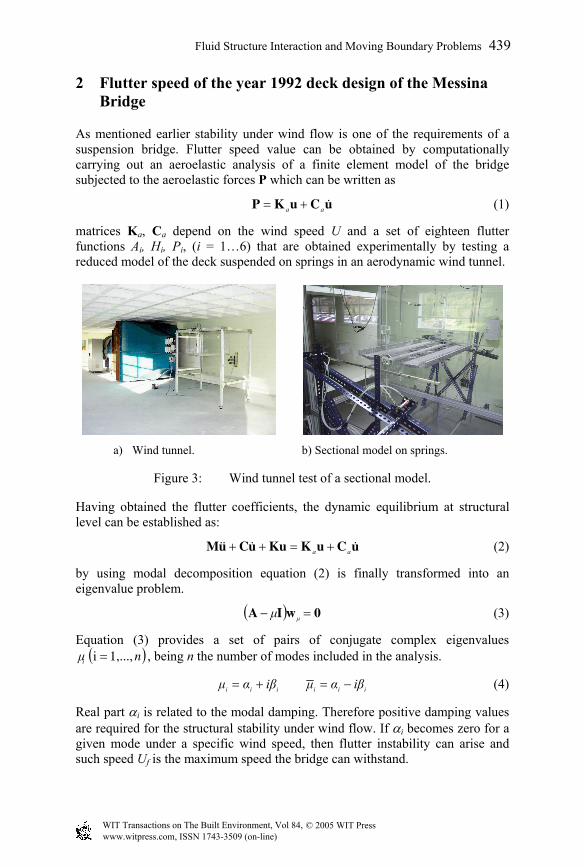
Therefore flutter speed Uf is obtained by solving the eigenvalue problem indicated in (3) according to the flowchart of figure 4 and then, values of wind speed are iteratively increased U until obtaining zero value for a given real part αj. Such procedure is shown in figure 5.
Figure 4: Flow diagram of eigenvalue problem.
Figure 5: Flow diagram of flutter speed.
Identification of flutter speed by this methodology was done in the past for different authors [4-6] using a partial set of the flutter coefficients, namely Ai, Hi, (i = 1…3) which were the only known at that moment. A summary of the numerical values of the flutter speed Uf obtained by these research groups is shown in table 1.
Table 1: Flutter speed of year 1992 deck design.
Authors Uf (m/s) Politecnico de Milano > 80 D’Asdia & Sepe 94 University of Yokohama 62-82 University of Coruña 87
440 Fluid Structure Interaction and Moving Boundary Problems
© 2005 WIT Press WIT Transactions on The Built Environment, Vol 84, www.witpress.com, ISSN 1743-3509 (on-line)

a) Two external planes.
b) Two central planes.
c) Four planes.
d) Three planes.
Figure 6: Cable configurations under study.
Fluid Structure Interaction and Moving Boundary Problems 441
© 2005 WIT Press WIT Transactions on The Built Environment, Vol 84, www.witpress.com, ISSN 1743-3509 (on-line)
It can be observed that not all the numerical values are above the lower limit of 75 m/s required by the specifications of the project. Therefore there is room for variations in the design of the bridge, in order to improve the aeroelastic responses. Several changes such as tower height, deck shape, cable location, can be made for this aim. The last topic is the subject of the present research work.
3 Classes of cable configurations considered for the Messina Bridge
The parametric study to compare efficiency level for several cable configurations was made for the recent year 2002 deck design as shown in Figure 2b. The following parameters were considered a) Location of cables. b) Existence of central clamps. Regarding to the location of cables, four types of distributions were taken in account. a) Two external cable planes, having two cables for each of them. This
alternative corresponds to the current preliminary design. b) Two central cable planes. c) Four cable planes. In this case cables were placed at both ends of the
motorway boxes. d) Three cable planes. This solution consisted of two external planes with only a
cable in each of them and a central plane with two cables. Figure 6 shows the deck shape for each of the configurations studied.
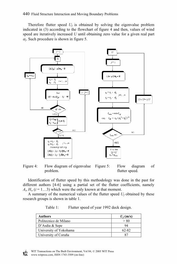
Effectiveness of a rigid link between cable and deck at the center of the span by means of a clamp is a topic under discussion among aeroelastic experts. Figure 7a shows the clamp installed in the suspension Great Belt Bridge, while no device of this short exists in the Akashi Bridge, as indicated in Figure 7b.
b) Clamp in Great Belt. b) Akashi Bridge.
Figure 7: Center span at Great Belt and Akashi bridges.
442 Fluid Structure Interaction and Moving Boundary Problems
© 2005 WIT Press WIT Transactions on The Built Environment, Vol 84, www.witpress.com, ISSN 1743-3509 (on-line)
4 Comparative efficiency of flutter stability of cable configuration in the Messina Bridge
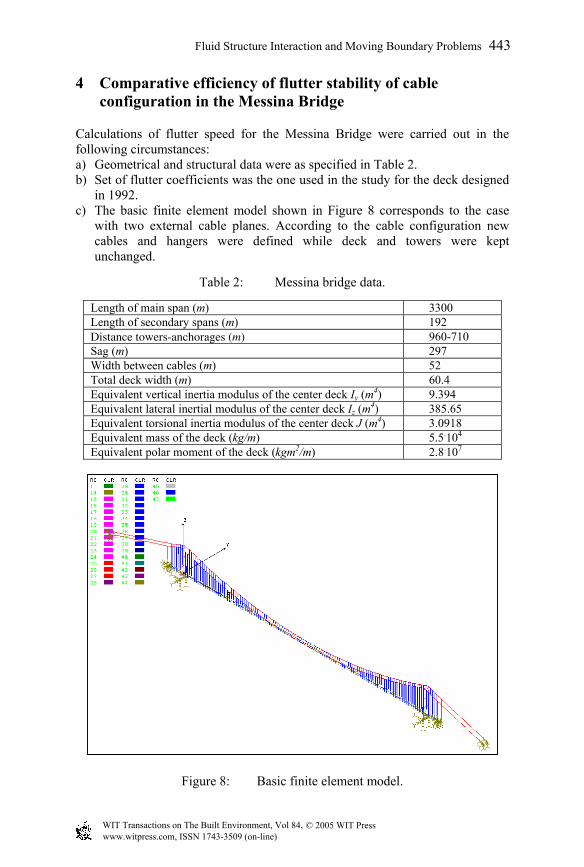
Calculations of flutter speed for the Messina Bridge were carried out in the following circumstances: a) Geometrical and structural data were as specified in Table 2. b) Set of flutter coefficients was the one used in the study for the deck designed
in 1992. c) The basic finite element model shown in Figure 8 corresponds to the case
with two external cable planes. According to the cable configuration new cables and hangers were defined while deck and towers were kept unchanged.
Table 2: Messina bridge data.
Length of main span (m) 3300 Length of secondary spans (m) 192 Distance towers-anchorages (m) 960-710 Sag (m) 297 Width between cables (m) 52 Total deck width (m) 60.4 Equivalent vertical inertia modulus of the center deck Iy (m4) 9.394 Equivalent lateral inertial modulus of the center deck Iz (m4) 385.65 Equivalent torsional inertia modulus of the center deck J (m4) 3.0918 Equivalent mass of the deck (kg/m) 5.5.104 Equivalent polar moment of the deck (kgm2/m) 2.8.107
Figure 8: Basic finite element model.
Fluid Structure Interaction and Moving Boundary Problems 443
© 2005 WIT Press WIT Transactions on The Built Environment, Vol 84, www.witpress.com, ISSN 1743-3509 (on-line)
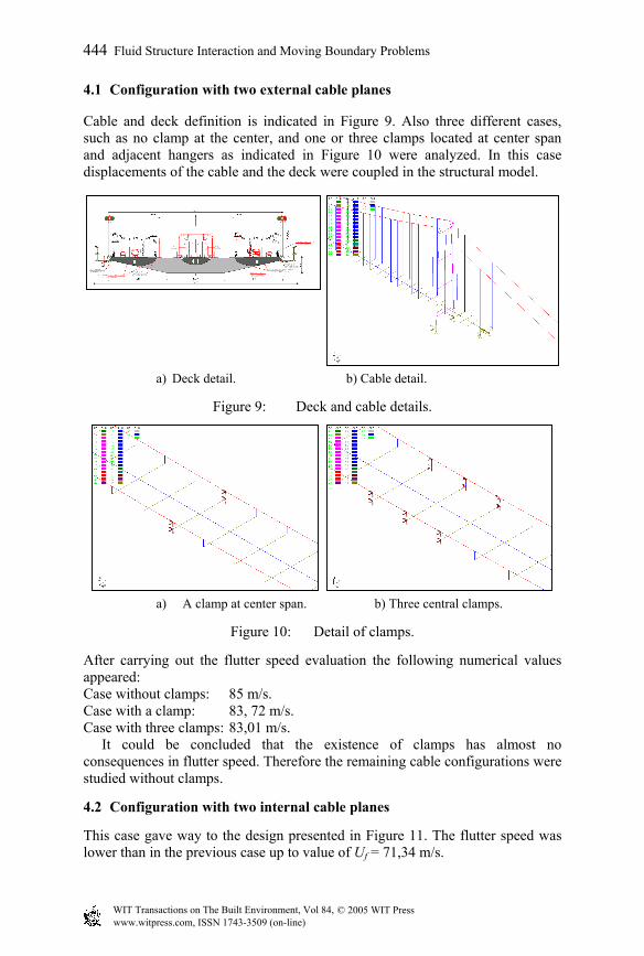
4.1 Configuration with two external cable planes
Cable and deck definition is indicated in Figure 9. Also three different cases, such as no clamp at the center, and one or three clamps located at center span and adjacent hangers as indicated in Figure 10 were analyzed. In this case displacements of the cable and the deck were coupled in the structural model.
a) Deck detail. b) Cable detail.
Figure 9: Deck and cable details.
a) A clamp at center span. b) Three central clamps.
Figure 10: Detail of clamps.
After carrying out the flutter speed evaluation the following numerical values appeared: Case without clamps: 85 m/s. Case with a clamp: 83, 72 m/s. Case with three clamps: 83,01 m/s. It could be concluded that the existence of clamps has almost no consequences in flutter speed. Therefore the remaining cable configurations were studied without clamps.
4.2 Configuration with two internal cable planes
This case gave way to the design presented in Figure 11. The flutter speed was lower than in the previous case up to value of Uf = 71,34 m/s.
444 Fluid Structure Interaction and Moving Boundary Problems
© 2005 WIT Press WIT Transactions on The Built Environment, Vol 84, www.witpress.com, ISSN 1743-3509 (on-line)
a) Bridge deck. b) Cable detail.
Figure 11: Deck and cable detail.
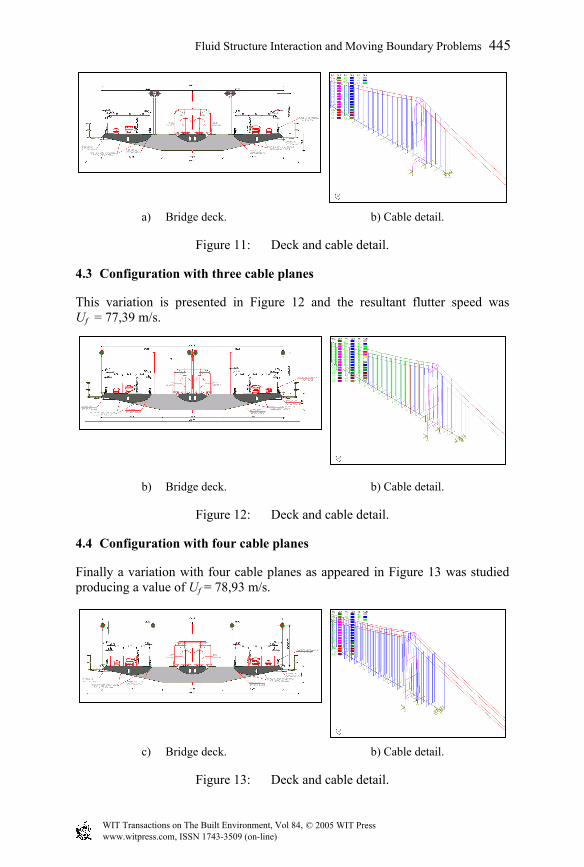
4.3 Configuration with three cable planes
This variation is presented in Figure 12 and the resultant flutter speed was Uf = 77,39 m/s.
b) Bridge deck. b) Cable detail.
Figure 12: Deck and cable detail.
4.4 Configuration with four cable planes
Finally a variation with four cable planes as appeared in Figure 13 was studied producing a value of Uf = 78,93 m/s.
c) Bridge deck. b) Cable detail.
Figure 13: Deck and cable detail.
Fluid Structure Interaction and Moving Boundary Problems 445
© 2005 WIT Press WIT Transactions on The Built Environment, Vol 84, www.witpress.com, ISSN 1743-3509 (on-line)

4.5 Summary of numerical results
A comparison of Uf values is presented in Table 3. It can be observed that the case with two central planes is the worst design. Cases with three and four cable planes behave worse for aeroelastic purposes than the prototype with only external cables, but they can save material for the huge transversal beams because this solution diminish the span of them.
Table 3: Comparison of flutter speed.
Cable configuration Uf (m/s) Two external planes. No clamp 85,50 Two external planes. A clamp 83,72 Two external planes. Three clamps 83,01 Four planes 78,93 Three planes 77,39 Two internal planes 71,34
5 Conclusions The Messina strait bridge is a challenging structure that deserves a lot of research before it goes into the construction phase. A study of efficiency of cable configuration to find out their relative efficiency in terms of flutter speeds shows that prototypes with external cables have better quality but penalizes sizing of transversal beams. Therefore a more complex study on static loads needs to be done. Flutter speed has been obtained with an incomplete set of the flutter coefficients. Consequently new studies taking into account the whole set of eighteen coefficients must be carried out.
References
[1] Ito, M., 21 St. “Century super span bridges in Japan”, in Bridge Aerodynamics, pp. 145-152, A. Larsen & S. Esdall (eds.), Balkema, 1998.
[2] Hernández, S., “The Rias Altas link. A challenging crossing”, in Strait Crossing 2001, pp. 407-414, J. Krokebas (ed.) Balkema, 2001.
[3] Ponte sullo Strello di Messina. “Studi e approfundamenti dell’opera di attraversamento. Sttretto di Messina S.p.A.”, 2003.
[4] T. Miyata, H. Yamada, H. Katsuchi, “Comparative analysis of Messina Bridge International Benchmark Study”. Proceedings of the 11th International Conference on Wind Engineering. June 2-5 2003, Lubbock, Texas, USA.
[5] D’Asdia, P. & Sepe, V.: “Aeroelastic instability of long-span suspension bridges: a multimode approach”. Journal of Wind Engineering and Industrial Aerodynamics, 74-76 (1998), pp 849-857.
[6] Jurado, J. A. & Hernández, S: “Sensitivity analysis of bridge flutter with respect to mechanical parameters of the deck”. Journal of Research in Structural and Multidisciplinary Optimization, Vol. 27, number 4, p.p. 272-283, June 2004.
446 Fluid Structure Interaction and Moving Boundary Problems
© 2005 WIT Press WIT Transactions on The Built Environment, Vol 84, www.witpress.com, ISSN 1743-3509 (on-line)