A Comparison of CEN and ASTM Test Methods for ... Office of Aviation Research Washington, D.C. 20591...
119
DOT/FAA/AR-04/24 Office of Aviation Research Washington, D.C. 20591 A Comparison of CEN and ASTM Test Methods for Composite Materials June 2004 Final Report This document is available to the U.S. public through the National Technical Information Service (NTIS), Springfield, Virginia 22161. U.S. Department of Transportation Federal Aviation Administration
Transcript of A Comparison of CEN and ASTM Test Methods for ... Office of Aviation Research Washington, D.C. 20591...

DOT/FAA/AR-04/24 Office of Aviation Research Washington, D.C. 20591
A Comparison of CEN and ASTM Test Methods for Composite Materials June 2004 Final Report This document is available to the U.S. public through the National Technical Information Service (NTIS), Springfield, Virginia 22161.
U.S. Department of Transportation Federal Aviation Administration
NOTICE
This document is disseminated under the sponsorship of the U.S. Department of Transportation in the interest of information exchange. The United States Government assumes no liability for the contents or use thereof. The United States Government does not endorse products or manufacturers. Trade or manufacturer’s names appear herein solely because they are considered essential to the objective of this report. This document does not constitute FAA certification policy. Consult your local FAA aircraft certification office as to its use. This report is available at the Federal Aviation Administration William J. Hughes Technical Center’s Full-Text Technical Reports page: actlibrary.tc.faa.gov in Adobe Acrobat portable document format (PDF).

Technical Report Documentation Page 1. Report No. DOT/FAA/AR-04/24
2. Government Accession No. 3. Recipient's Catalog No.
4. Title and Subtitle
A COMPARISON OF CEN AND ASTM TEST METHODS FOR COMPOSITE 5. Report Date
June 2004 MATERIALS 6. Performing Organization Code
7. Author(s)
Daniel O. Adams 8. Performing Organization Report No.
9. Performing Organization Name and Address
Department of Mechanical Engineering University of Utah
10. Work Unit No. (TRAIS)
Salt Lake City, Utah 84112 11. Contract or Grant No.
12. Sponsoring Agency Name and Address
U.S. Department of Transportation Federal Aviation Administration
13. Type of Report and Period Covered
Final Report
Office of Aviation Research Washington, DC 20591
14. Sponsoring Agency Code
AIR-120 15. Supplementary Notes
The FAA William J. Hughes Technical Center Technical Monitor was Peter Shyprykevich. 16. Abstract
A detailed test method comparison was performed to assess the equivalence of test methods for composite materials, with emphasis on the Committee for European Standardization and ASTM International test methods referred to in the SAE International Aerospace Material Specification (AMS) 2980 and 3970 specifications. This comparison included both the parameters associated with two comparable test methods and the additions and changes listed in the AMS specifications. For the types of tests where only one test method is referred to in the SAE specifications, a second comparable ASTM or Suppliers of Advanced Composite Materials Association test method was selected for comparison purposes. In total, two test methods were reviewed and compared for a total of 16 different types of tests. For each type of test, three comparison tables are presented, focusing on geometric features of the specimen and test fixture, parameters associated with the test procedure, and procedures for data reduction and reporting. Each table contains a list of individual parameters specified in the test methods as well as any additions or changes provided in the AMS 2980 and 3970 specifications. For every parameter listed in the comparison tables, an assessment of the equivalence was made using a 0-4 rating scale. A brief summary of each test method comparison is provided, which emphasizes the most significant differences between the test methods. Based on the comparative assessments performed, 4 of the 16 types of tests were recommended for follow-on testing to further assess test method equivalency. Note that the selection of these four tests for follow-on testing only reflects the need for additional test data to assess equivalency and is not a reflection of their degree of equivalency relative to the other tests. The four types of tests recommended for follow-on testing are lamina compression testing to assess the effects of gage length, laminate compression testing to assess the effects of loading method, in-plane shear testing to investigate the effects of specimen thickness, and constituent content determinations to investigate the effects of specimen size and weighing accuracy. 17. Key Words
Composite materials, Mechanical property testing, Test methods
18. Distribution Statement
This document is available to the public through the National Technical Information Service (NTIS) Springfield, Virginia 22161.
19. Security Classif. (of this report)
Unclassified
20. Security Classif. (of this page)
Unclassified
21. No. of Pages
120 22. Price
Form DOT F1700.7 (8-72) Reproduction of completed page authorized

TABLE OF CONTENTS Page EXECUTIVE SUMMARY vii 1. INTRODUCTION 1
1.1 Background to Comparison Study 1 1.2 Method of Comparative Evaluation 2
2. TEST METHOD COMPARISONS 3
2.1 Lamina Tension Testing 4 2.2 Laminate Tension Testing 12 2.3 Open-Hole Tension Testing 18 2.4 Lamina Compression Testing 23 2.5 Laminate Compression Testing 28 2.6 Open-Hole Compression Testing 33 2.7 Filled-Hole Compression Testing 40 2.8 In-Plane Shear Testing 47 2.9 Bearing Strength Testing 53 2.10 Compression After Impact Testing 61 2.11 Mode I Fracture Toughness Testing 69 2.12 Mode II Fracture Toughness Testing 76 2.13 Glass Transition Temperature Determination 84 2.14 Constituent Content Determination 90 2.15 Moisture Conditioning Procedure 94 2.16 Fluid Immersion Procedure 102
3. FOLLOW-ON TESTING 110
3.1 Lamina Compression Testing: Effects of Gage Length 110
3.2 Laminate Compression Testing: Effects of Loading Method 110
3.3 In-Plane Shear Testing: Effects of Specimen Thickness 110
3.4 Constituent Content Determination: Effects of Specimen Size and Weighing Accuracy 111
4. CONCLUSIONS 111
5. REFERENCES 112
iii
LIST OF TABLES Table Page 1 Lamina Tension Testing (Warp/Weft)—Specimen Geometric Comparisons 5
2 Lamina Tension Testing (Warp/Weft)—Test Procedure Comparisons 7
3 Lamina Tension Testing (Warp/Weft)—Data Reduction/Reporting Comparisons 9
4 Laminate Tension Testing 13
5 Laminate Tension Testing—Test Procedure Comparisons 15
6 Laminate Tension Testing—Data Reduction/Reporting Comparisons 16
7 Open-Hole Tension Testing—Specimen Geometric Comparisons 19
8 Open-Hole Tension Testing—Test Procedure Comparisons 20
9 Open-Hole Tension Testing—Data Reduction/Reporting Comparisons 21
10 Lamina Compression Testing (Warp/Weft)—Specimen Geometric Comparisons 24
11 Lamina Compression Testing (Warp/Weft)—Test Procedure Comparisons 26
12 Lamina Compression Testing (Warp/Weft)—Data Reduction/Reporting Comparisons 27
13 Laminate Compression Testing—Specimen/Fixture Geometric Comparisons 29
14 Laminate Compression Testing 30
15 Laminate Compression Testing—Data Reduction/Reporting Comparisons 31
16 Open-Hole Compression Testing—Specimen/Fixture Geometric Comparisons 34
17 Open-Hole Compression Testing—Test Procedure Comparisons 36
18 Open-Hole Compression Testing—Data Reduction/Reporting Comparisons 38
19 Filled-Hole Compression Testing—Specimen/Fixture Geometric Comparisons 41
20 Filled-Hole Compression Testing—Test Procedure Comparisons 43
21 Filled-Hole Compression Testing—Data Reduction/Reporting Comparisons 45
22 Tensile In-Plane Shear Testing—Specimen Geometric Comparisons 48
23 Tensile In-Plane Shear Testing—Test Procedure Comparisons 49
iv

24 Tensile In-Plane Shear Testing—Data Reduction/Reporting Comparisons 51
25 Bearing Testing—Specimen Geometric Comparisons 54
26 Bearing Testing—Test Procedure Comparisons 56
27 Bearing Testing—Data Reduction/Reporting Comparisons 58
28 Compression After Impact Testing—Specimen/Fixture Geometric Comparisons 62
29 Compression After Impact Testing—Test Procedure Comparisons 64
30 Compression After Impact Testing—Data Reduction/Reporting Comparisons 67
31 Mode I Fracture Toughness Testing—Specimen Geometric Comparisons 70
32 Mode I Fracture Toughness Testing—Test Procedure Comparisons 71
33 Mode I Fracture Toughness Testing—Data Reduction/Reporting Comparisons 74
34 Mode II Fracture Toughness Testing—Specimen Geometric Comparisons 77
35 Mode II Fracture Toughness Testing—Test Procedure Comparisons 79
36 Mode II Fracture Toughness Testing—Data Reduction/Reporting Comparisons 82
37 Glass Transition Temperature Testing—Specimen Geometric Comparisons 85
38 Glass Transition Temperature Testing—Test Procedure Comparisons 86
39 Glass Transition Temperature Testing—Data Reduction/Reporting Comparisons 88
40 Constituent Content—Specimen Geometric Comparisons 91
41 Constituent Content—Test Procedure Comparisons 92
42 Constituent Content—Data Reduction/Reporting Comparisons 93
43 Moisture Conditioning—Specimen Geometric Comparisons 95
44 Moisture Conditioning—Test Procedure Comparisons 96
45 Moisture Conditioning—Data Reduction/Reporting Comparisons 100
46 Fluid Immersion Method—Specimen Geometric Comparisons 103
47 Fluid Immersion Method—Test Procedure Comparisons 104
48 Fluid Immersion Method—Data Reduction/Reporting Comparisons 108
v/vi

EXECUTIVE SUMMARY
A detailed test method comparison was performed to assess the equivalence of test methods for composite materials, with emphasis on the Committee for European Standardization and ASTM International test methods referred to in the SAE International Aerospace Material Specification (AMS) 2980 and 3970 specifications. This comparison included both the parameters associated with two comparable test methods and the additions and changes listed in the AMS specifications. For the types of tests where only one test method is referred to in the SAE specifications, a second comparable ASTM or Suppliers of Advanced Composite Materials Association test method was selected for comparison purposes. In total, two test methods were reviewed and compared for a total of 16 different types of tests. For each type of test, three comparison tables are presented, focusing on geometric features of the specimen and test fixture, parameters associated with the test procedure, and procedures for data reduction and reporting. Each table contains a list of individual parameters specified in the test methods as well as any additions or changes provided in the AMS 2980 and 3970 specifications. For every parameter listed in the comparison tables, an assessment of the equivalence was made using a 0-4 rating scale. A brief summary of each test method comparison is provided, which emphasizes the most significant differences between the test methods. Based on the comparative assessments performed, 4 of the 16 types of tests were recommended for follow-on testing to further assess test method equivalency. Note that the selection of these four tests for follow-on testing only reflects the need for additional test data to assess equivalency and is not a reflection of their degree of equivalency relative to the other tests. The four types of tests recommended for follow-on testing are lamina compression testing to assess the effects of gage length, laminate compression testing to assess the effects of loading method, in-plane shear testing to investigate the effects of specimen thickness, and constituent content determinations to investigate the effects of specimen size and weighing accuracy.
vii/viii

1. INTRODUCTION.
1.1 BACKGROUND TO COMPARISON STUDY.
The motivation for this comparative evaluation of U.S. and European test methods for composite materials dates back to the early 1990s. At that time, a composite materials characterization program was initiated to generate a data set and subsequently qualify a composite material system for commercial aircraft repair [1]. The material to be qualified was a wet lay-up composite material to be processed with a vacuum-only cure and used for airframe repair. The carbon fiber used (HTA 5131, Tenax Fibers, Wuppertal, Germany) was woven into a 3 K plain weave (Hexcel Fabrics S.A., Lyon, France) and impregnated with Epocast 52 A/B epoxy resin (Vantico A&T, Los Angeles, CA). Two resin impregnation methods were used, referred to as the squeeze-out method and the vertical bleed method. A variety of laminate and sandwich panel configurations were produced and cured at 200°F under vacuum pressure. The material qualification program was performed according to SAE International Aerospace Material Specification (AMS) 2980 [2] and Commercial Aircraft Composite Repair Committee (CACRC) requirements, which used Committee for European Standardization (CEN) test methods. The goal of this material characterization program, sponsored by the manufacturers of the fiber and resin, was to qualify a composite material system to be used in the repair of composite structures on commercial aircraft. Mechanical testing performed included tension, compression, in-plane shear, open-hole tension, filled-hole tension, open-hole compression, filled-hole compression, bearing, compression-after-impact, tension-tapered joint, and tension-stepped joint tests. At the completion of testing, the mechanical test results were processed into MIL Handbook-acceptable form to provide statistical data. In the mid-1990s, a MIL-Handbook-17 Composite Materials Handbook Committee reviewed the test methods used in this material qualification program and compared them to the test methods recommended by MIL-HDBK-17 [3]. They noted that CEN test methods were used extensively in this qualification program, whereas MIL-HDBK-17 focuses on ASTM International test methods. The MIL-HDBK-17 committee determined that the CEN and ASTM test methods differed in several aspects, raising concerns that the SAE specified tests do not produce equivalent results to the MIL-HDBK-17-recommended test methods. Results of the MIL-HDBK-17 committee review were published by email in October 1995 [4]. Following this review, discussions continued between MIL-HDBK-17 and CACRC personnel. Although the CACRC continued using CEN test methods, similar ASTM test methods were added to the SAE specifications as an alternate for some tests. Additionally, for several types of tests included in both SAE AMS 2980 [2] (for wet lay-up material) and SAE AMS 3970 [5] (for prepreg material), several parameters were specified that limited potential differences in test results between the CEN and ASTM test methods. For several types of tests, however, it remained unclear if the ASTM and CEN test methods would produce equivalent test results. In May 2002, a joint meeting was held between CACRC and the MIL-HDBK-17 committees. Following this meeting, Mr. Rich Fields reviewed the test methods in the initial release of SAE AMS 3970 [5] and wrote a summary of findings and conclusions [6]. Mr. Fields concluded that results from some CEN test methods would not be expected to be equivalent to results for the same properties obtained using MIL-HDBK-17-recommended test methods.
1

The detailed test method comparison contained in this report is directed towards assessing the equivalence of the different test methods (primarily CEN and ASTM) referred to in the SAE AMS 2980 and 3970 specifications. Of interest is both a direct comparison of the test methods as well as an investigation of the effects of additions and changes given in the AMS specifications. For the types of tests where only one test method is referred to in the SAE specifications, a second comparable ASTM or Suppliers of Advanced Composite Materials Association (SACMA) test method was selected for comparison purposes. In total, two test methods were reviewed and compared for a total of 16 different types of tests. In addition to a detailed comparison of test method parameters, the significance of differences in parameters was assessed. For those tests where the significance of an important difference was not known, follow-on mechanical testing was proposed for the second round of this investigation. The types of tests recommended for follow-on mechanical testing and the specific parameters to be assessed are summarized in the final section of this report. 1.2 METHOD OF COMPARATIVE EVALUATION.
For each of the 16 types of tests considered, two different test methods were carefully reviewed and compared. For each type of test, the results of the comparative evaluation have been arranged into three comparison tables. The first table focuses on geometric features of the specimen and test fixture. Included in this table are important dimensions and tolerances associated with both the test specimen and fixture. The second table focuses on parameters associated with the test procedure, which include parameters associated with specimen preparation and instrumentation, procedures for specimen preconditioning, loading, and testing, and accuracy requirements for measured quantities. The third table focuses on procedures for data reduction and reporting, which include procedures, formulas, and statistical methods used to calculate and report test quantities. In addition to listing specific parameters associated with each of the test methods reviewed, the significance of differences in parameters was assessed and included in the comparison tables. For every parameter compared, an assessment of the equivalence was made using the following rating scale: • 0—No difference, essentially the same, not expected to produce any effect on results
• 1—Insignificant difference, potential to produce insignificant effect on results
• 2—Minimal difference, difference of minimal significance, potential to produce minimal effect on results
• 3—Moderate difference, difference of moderate significance, potential to produce moderate effect on results
• 4—Major difference, difference of major significance, potential to produce major effect on results
• NC—Not comparable
2

An initial draft of these comparison tables was prepared and distributed to a selected group for evaluation. This group of evaluators consisted of:
• Mr. Rich Fields, Lockheed Martin Orlando, Chairman of ASTM D 30 Committee and Co-Chairman of MIL-HDBK-17 Testing Working Group
• Mr. Peter Shyprykevich, Federal Aviation Administration
• Dr. Donald F. Adams, President of Wyoming Test Fixtures, Inc.
• Dr. John Tomblin, Director of the National Institute for Aviation Research at Wichita State University
The author and evaluators met at Wichita State University in August 2003 to discuss the comparison and assessment tables as well as to determine which tests would require follow-on testing to assess equivalence. As a result of this meeting, changes were made to both the format and the content of the comparison and assessment tables. Additionally, four types of tests were identified as requiring follow-on testing in the second round of this investigation to assess equivalence.
In the following section, test methods are compared for 16 types of tests for composite materials. A brief summary of the comparison is followed by the three comparative tables for each type of test. The final section of this report presents the tests that were identified as requiring follow-on testing in the second round of this investigation to assess equivalence.
2. TEST METHOD COMPARISONS.
In this section, each of the 16 types of tests is compared and the significance of differences is assessed. Three comparison tables are presented, focusing on geometric features of the specimen and test fixture, parameters associated with the test procedure, and procedures for data reduction and reporting. Each table contains a list of individual parameters specified in the test methods as well as any additions or changes provided in the AMS 2980 and 3970 specifications. The column of AMS-specified additions/changes is placed between the columns containing the description of parameters from the two test methods. The column heading for the AMS specifications states which of the test methods the additions/changes are intended to modify. For further clarification, the column of AMS additions/changes is separated from the test methods by either a single line or double line, depending on whether the test method is included in the AMS specifications. A single line () is used when the test method is listed in the AMS specifications, whereas a double line () is used when the test method is not listed.
For every parameter listed in the comparison tables, an assessment of the equivalence was made using a 0-4 rating scale. The definitions used for each number rating are:
• 0—No difference, essentially the same, not expected to produce any effect on results
• 1—Insignificant difference, potential to produce insignificant effect on results
• 2—Minimal difference, difference of minimal significance, potential to produce minimal effect on results
3

• 3—Moderate difference, difference of moderate significance, potential to produce moderate effect on results
• 4—Major difference, difference of major significance, potential to produce major effect on results
For cases where an assessment of equivalence is not possible, a rating of NC (not comparable) is used. A brief summary of each test method comparison is provided, which emphasizes the most significant differences between the test methods.
In the comparisons that follow, the two test methods selected were based on those referred to in the AMS specifications. For several types of tests, both a CEN and an ASTM test method are referred to in the AMS specification and are, therefore, used for comparison. In several other cases, however, only a CEN test method is referred to in the AMS specifications. For these cases, a similar ASTM test method existed, either a draft ASTM standard or a SACMA-recommended method was selected. For one type of test, the AMS specifications referred only to a SACMA-recommended method. For this case, a comparable ASTM standard was identified and used for comparison.
Of the CEN test methods used for comparison, several of the standards are currently draft or preliminary standards and are denoted as prEN test methods. Other test methods, which have been approved by CEN, are denoted as EN test methods.
2.1 LAMINA TENSION TESTING.
The two test methods considered, EN 2561 and ASTM D 3039, are similar test methods for determining tensile properties of composite materials (tables 1 through 3). However, EN 2561 is limited in scope to 0° unidirectional carbon fiber composites, whereas ASTM D 3039 is applicable to balanced and symmetric laminates as well as discontinuous fiber polymer composites. The AMS 2980 and 3970 specifications provide additions and changes to either standard for testing woven fabric laminates. Although different specimen widths and thicknesses are specified for the different types of laminates (unidirectional, woven fabric, and balanced and symmetric laminates), the stated widths are consistent among the specifications for each laminate type.
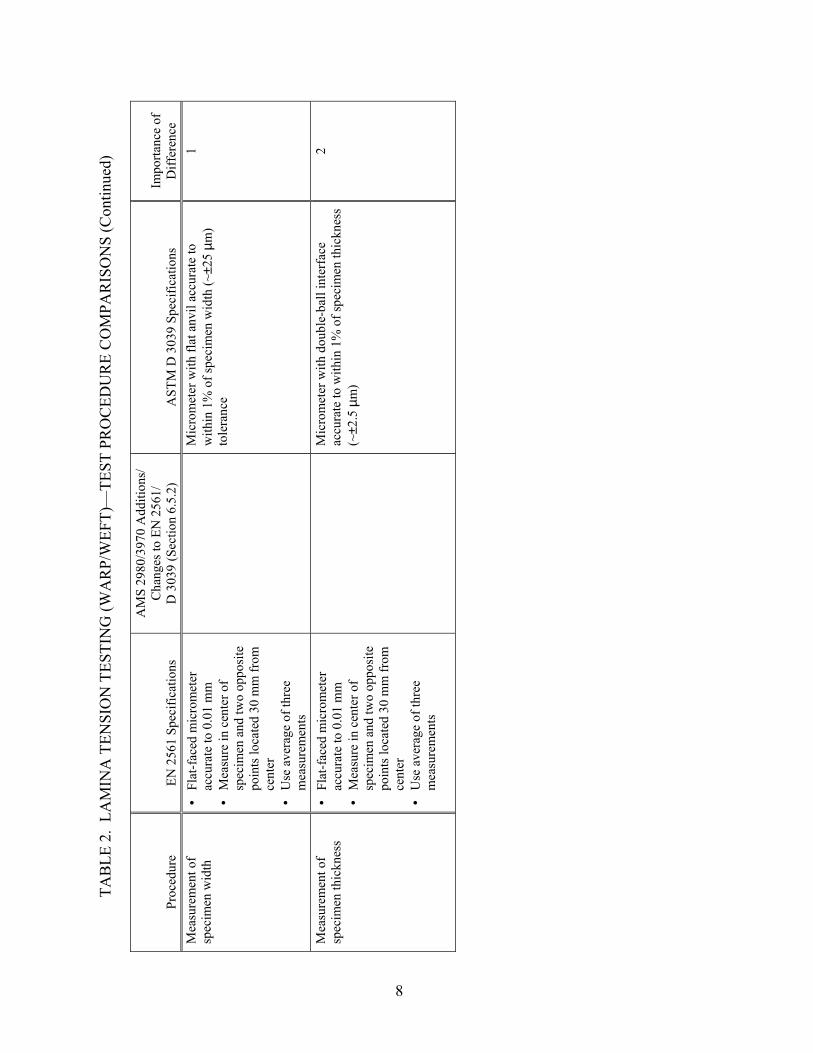
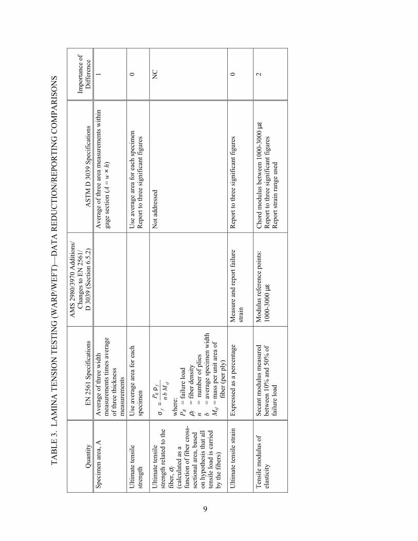
A comparison of specimen geometries revealed only minor differences in dimensions and tolerances that were considered to produce insignificant effects on results. Differences in tabbing requirements may produce a minimal effect on results. Whereas both EN 2561 and ASTM D 3039 specify a minimum of five specimens, the AMS 2980 and 3970 specifications require six specimens. Different micrometers specified in EN 2561 and ASTM D 3039 for measuring specimen thickness as well as different data ranges for calculating the modulus of elasticity and Poisson’s ratio may produce minimal effects on results. Whereas ASTM D 3039 requires the reporting of failure modes to follow a three-part code and does not specify requirements for acceptable failures, the EN 2561 and the AMS specifications require that specimens fail within the gage section (between the grips) but do not require the reporting of the observed failure mode.
4

TAB
LE 1
. LA
MIN
A T
ENSI
ON
TES
TIN
G (W
AR
P/W
EFT)
—SP
ECIM
EN G
EOM
ETR
IC C
OM
PAR
ISO
NS
Prop
erty
EN
256
1 Sp
ecifi
catio
ns
AM
S 29
80/3
970
Add
ition
s/
Cha
nges
to E
N 2
561/
D
303
9 (S
ectio
n 6.
5.2)
A
STM
D 3
039
Spec
ifica
tions
Im
porta
nce
of
Diff
eren
ce
Lam
inat
e la
y-up
0°
Uni
dire
ctio
nal (
Spec
imen
ax
is p
aral
lel t
o th
e di
rect
ion
of
the
fiber
s)
[(90
/0)]
4S (T
ensi
le W
eft)
(AM
S 29
80-2
) [(
0/90
)]4S
(Ten
sile
War
p)
(AM
S 39
70-2
)
All
bala
nced
and
sym
met
ric la
min
ates
N
C
Ove
rall
spec
imen
le
ngth
25
0 ±1
mm
25
0 ±3
mm
B
alan
ced
and
sym
met
ric:
250
mm
0
Spec
imen
gag
e le
ngth
12
0 m
m
125
mm
min
imum
N
ot sp
ecifi
ed
NC
Spec
imen
wid
th
15 m
m (0
° uni
dire
ctio
nal,
Spec
imen
type
B)
25 m
m (w
oven
lam
inat
e)
0° u
nidi
rect
iona
l: 1
5 m
m
Bal
ance
d an
d sy
mm
etric
: 25
mm
N
C
Spec
imen
wid
th
tole
ranc
e ±0
.5 m
m
±0
.25
mm
0.
08-m
m p
aral
lelis
m
±1%
of s
peci
men
wid
th
0
Spec
imen
thic
knes
s 1
±0.2
mm
(0° u
nidi
rect
iona
l) (S
peci
men
type
B)
• •
0° u
nidi
rect
iona
l: 1
.0 m
m re
com
men
ded
Bal
ance
d an
d sy
mm
etric
: 2.
5 m
m
reco
mm
ende
d
0
Spec
imen
thic
knes
s to
lera
nce
Not
spec
ified
0.08
-mm
face
-to-f
ace
para
llelis
m
±4%
of s
peci
men
thic
knes
s 1
Use
of t
abs
Req
uire
d, u
nles
s usi
ng g
rips
with
adj
usta
ble
grip
pre
ssur
e O
ptio
nal,
to b
e ag
reed
be
twee
n pa
rties
invo
lved
A
s nee
ded
0
Tab
mat
eria
l 15
81 ty
pe g
lass
-epo
xy la
min
ate,
ar
rang
ed a
t ±45
°
Mos
t con
sist
ently
use
d: E
-gla
ss, w
oven
or
nonw
oven
, at ±
45° t
o lo
adin
g
0
Tab
leng
th
65 ±
15 m
m
(0° u
nidi
rect
iona
l)
• • 0°
uni
dire
ctio
nal:
56
mm
reco
mm
ende
d B
alan
ced
and
sym
met
ric:
fric
tion
tabs
re
com
men
ded
1
Tab
thic
knes
s B
etw
een
0.5
and
1.0
mm
• • 0°
uni
dire
ctio
nal:
1.5
mm
reco
mm
ende
d 90
°uni
dire
ctio
nal:
1.5
mm
reco
mm
ende
d
1
5

TAB
LE 1
. LA
MIN
A T
ENSI
ON
TES
TIN
G (W
AR
P/W
EFT)
—SP
ECIM
EN G
EOM
ETR
IC C
OM
PAR
ISO
NS
(Con
tinue
d)
Prop
erty
EN
256
1 Sp
ecifi
catio
ns
AM
S 29
80/3
970
Add
ition
s/
Cha
nges
to E
N 2
561/
D
303
9 (S
ectio
n 6.
5.2)
A
STM
D 3
039
Spec
ifica
tions
Im
porta
nce
of
Diff
eren
ce
Tab
thic
knes
s to
lera
nce
Not
spec
ified
±1
% o
f tab
thic
knes
s 2
Tab
beve
l ang
le
90° (
0° u
nidi
rect
iona
l)
0° u
nidi
rect
iona
l: 7
° or 9
0° re
com
men
ded
2
6

TAB
LE 2
. LA
MIN
A T
ENSI
ON
TES
TIN
G (W
AR
P/W
EFT)
—TE
ST P
RO
CED
UR
E C
OM
PAR
ISO
NS
Proc
edur
e EN
256
1 Sp
ecifi
catio
ns
AM
S 29
80/3
970
Add
ition
s/
Cha
nges
to E
N 2
561/
D
303
9 (S
ectio
n 6.
5.2)
A
STM
D 3
039
Spec
ifica
tions
Im
porta
nce
of
Diff
eren
ce
Load
indi
cato
r A
ccur
ate
to w
ithin
1%
of t
he
load
rang
e us
ed
A
ccur
acy
over
the
load
rang
e(s)
of i
nter
est
of w
ithin
±1%
of t
he in
dica
ted
valu
e 0
Grip
s Th
e ja
ws s
hall
entra
p th
e ta
bs
of th
e sp
ecim
ens
H
ighl
y de
sira
ble
to u
se ro
tatio
nally
self-
alig
ning
grip
s to
redu
ce b
endi
ng st
ress
1
Spec
imen
alig
nmen
t Su
ffic
ient
to a
void
the
intro
duct
ion
of a
ny b
endi
ng
load
s
R
ecom
men
ds li
miti
ng p
erce
nt b
endi
ng to
a
rang
e of
3%
-5%
for s
train
leve
ls >
100
0µε
0
Test
Spe
ed
2 m
m/m
in
C
onst
ant h
ead-
spee
d te
sts:
2 m
m/m
in
Stra
in c
ontro
lled
test
s: 0
.01
min
-1
0
Sam
plin
g M
inim
um o
f fiv
e Si
x sp
ecim
ens (
AM
S 29
80-2
an
d A
MS
3970
-2)
At l
east
five
spec
imen
s 2
Stra
in g
age
sele
ctio
n A
ccur
ate
to w
ithin
1%
in th
e st
rain
rang
e us
ed
• • •
Req
uire
d ac
tive
gage
leng
th o
f at l
east
3
mm
(6 m
m re
com
men
ded
for m
ost
mat
eria
ls)
Rec
omm
ende
d ac
tive
gage
leng
th ≥
the
char
acte
ristic
repe
atin
g un
it of
the
wea
ve
for w
oven
fabr
ic la
min
ates
R
ecom
men
ded
resi
stan
ce ≥
350
Ω
1
Exte
nsom
eter
s A
ccur
ate
to w
ithin
1%
in th
e st
rain
rang
e us
ed
• •
Rec
omm
ende
d ga
ge le
ngth
in th
e ra
nge
of 1
0 to
50
mm
Ex
tens
omet
er sh
all s
atis
fy P
ract
ice
E 83
1
Spec
imen
con
ditio
ning
• • •
• •
EN 2
743
for t
ests
in th
e in
itial
stat
e EN
248
9 fo
r tes
ts a
fter
imm
ersi
on
EN 2
823
for t
ests
afte
r hu
mid
ity e
xpos
ure
St
anda
rd la
bora
tory
atm
osph
ere:
23°
±3
°C a
nd 5
0% ±
10%
rela
tive
hum
idity
R
equi
res m
aint
aini
ng te
mpe
ratu
re to
w
ithin
±3°
C a
nd re
lativ
e va
por l
evel
to
with
in ±
3%
1
7
TAB
LE 2
. LA
MIN
A T
ENSI
ON
TES
TIN
G (W
AR
P/W
EFT)
—TE
ST P
RO
CED
UR
E C
OM
PAR
ISO
NS
(Con
tinue
d)
Proc
edur
e EN
256
1 Sp
ecifi
catio
ns
AM
S 29
80/3
970
Add
ition
s/
Cha
nges
to E
N 2
561/
D
303
9 (S
ectio
n 6.
5.2)
A
STM
D 3
039
Spec
ifica
tions
Im
porta
nce
of
Diff
eren
ce
Mea
sure
men
t of
spec
imen
wid
th
• • •
Flat
-fac
ed m
icro
met
er
accu
rate
to 0
.01
mm
M
easu
re in
cen
ter o
f sp
ecim
en a
nd tw
o op
posi
te
poin
ts lo
cate
d 30
mm
from
ce
nter
U
se a
vera
ge o
f thr
ee
mea
sure
men
ts
M
icro
met
er w
ith fl
at a
nvil
accu
rate
to
with
in 1
% o
f spe
cim
en w
idth
(~±2
5 µm
) to
lera
nce
1
Mea
sure
men
t of
spec
imen
thic
knes
s • • •
Flat
-fac
ed m
icro
met
er
accu
rate
to 0
.01
mm
M
easu
re in
cen
ter o
f sp
ecim
en a
nd tw
o op
posi
te
poin
ts lo
cate
d 30
mm
from
ce
nter
U
se a
vera
ge o
f thr
ee
mea
sure
men
ts
M
icro
met
er w
ith d
oubl
e-ba
ll in
terf
ace
accu
rate
to w
ithin
1%
of s
peci
men
thic
knes
s (~
±2.5
µm
)
2
8
TAB
LE 3
. LA
MIN
A T
ENSI
ON
TES
TIN
G (W
AR
P/W
EFT)
—D
ATA
RED
UC
TIO
N/R
EPO
RTI
NG
CO
MPA
RIS
ON
S
Qua
ntity
EN
256
1 Sp
ecifi
catio
ns
AM
S 29
80/3
970
Add
ition
s/
Cha
nges
to E
N 2
561/
D
303
9 (S
ectio
n 6.
5.2)
A
STM
D 3
039
Spec
ifica
tions
Im
porta
nce
of
Diff
eren
ce
Spec
imen
are
a, A
A
vera
ge o
f thr
ee w
idth
m
easu
rem
ents
tim
es a
vera
ge
of th
ree
thic
knes
s m
easu
rem
ents
A
vera
ge o
f thr
ee a
rea
mea
sure
men
ts w
ithin
ga
ge se
ctio
n (A
= w
× h
) 1
Ulti
mat
e te
nsile
st
reng
th
Use
ave
rage
are
a fo
r eac
h sp
ecim
en
U
se a
vera
ge a
rea
for e
ach
spec
imen
R
epor
t to
thre
e si
gnifi
cant
figu
res
0
Ulti
mat
e te
nsile
st
reng
th re
late
d to
the
fiber
, σf
(cal
cula
ted
as a
fu
nctio
n of
fibe
r cro
ss-
sect
iona
l are
a, b
ased
on
hyp
othe
sis t
hat a
ll te
nsile
load
is c
arrie
d by
the
fiber
s)
sffR
f Mb n
Pρ
=σ
whe
re:
P R
= fa
ilure
load
ρ f
=
fiber
den
sity
n
=
num
ber o
f plie
s b
=
aver
age
spec
imen
wid
th
Msf =
mas
s per
uni
t are
a of
fib
er (p
er p
ly)
Not
addr
esse
dN
C
Ulti
mat
e te
nsile
stra
in
Expr
esse
d as
a p
erce
ntag
e M
easu
re a
nd re
port
failu
re
stra
in
Rep
ort t
o th
ree
sign
ifica
nt fi
gure
s 0
Tens
ile m
odul
us o
f el
astic
ity
Seca
nt m
odul
us m
easu
red
betw
een
10%
and
50%
of
failu
re lo
ad
Mod
ulus
refe
renc
e po
ints
: 10
00-3
000
µε
Cho
rd m
odul
us b
etw
een
1000
-300
0 µε
R
epor
t to
thre
e si
gnifi
cant
figu
res
Rep
ort s
train
rang
e us
ed
2
9

TAB
LE 3
. LA
MIN
A T
ENSI
ON
TES
TIN
G (W
AR
P/W
EFT)
—D
ATA
RED
UC
TIO
N/R
EPO
RTI
NG
CO
MPA
RIS
ON
S (C
ontin
ued)
Qua
ntity
EN
256
1 Sp
ecifi
catio
ns
AM
S 29
80/3
970
Add
ition
s/
Cha
nges
to E
N 2
561/
D
303
9 (S
ectio
n 6.
5.2)
A
STM
D 3
039
Spec
ifica
tions
Im
porta
nce
of
Diff
eren
ce
Tens
ile m
odul
us o
f el
astic
ity re
late
d to
the
fiber
, Ef
(cal
cula
ted
as a
fu
nctio
n of
fibe
r cro
ss-
sect
iona
l are
a, b
ased
on
the
hypo
thes
is th
at
all t
ensi
le lo
ad is
ca
rrie
d by
the
fiber
s)
εn
b M
ρP
sf
fR
f∆
∆=
σ
whe
re:
∆PR
= di
ffer
ence
in fa
ilure
lo
ad
ρ f
= fib
er d
ensi
ty
n =
num
ber o
f plie
s b
= av
erag
e sp
ecim
en
wid
th
Msf
= m
ass p
er u
nit a
rea
of
fiber
(per
ply
) ∆ ε
=
diff
eren
ce in
axi
al
stra
ins
N
otad
dres
sed
NC
Pois
son’
s rat
io
Mea
sure
d be
twee
n 10
% a
nd
50%
of f
ailu
re lo
ad
C
hord
met
hod:
bet
wee
n 10
00-3
000
µε
Rep
ort t
o th
ree
sign
ifica
nt fi
gure
s R
epor
t stra
in ra
nge
used
2
Failu
re M
ode
Failu
re sh
all o
ccur
with
in th
e fr
ee le
ngth
of t
he sp
ecim
en b
ut
may
ext
end
unde
r the
end
tabs
or
with
in th
e te
st m
achi
ne ja
ws
Tens
ion
failu
re w
ithin
the
gage
le
ngth
late
ral a
ngle
dire
ctio
n R
epor
t mod
e an
d lo
catio
n of
failu
re u
sing
th
ree
part
failu
re m
ode
code
(giv
en in
st
anda
rd)
2
Stat
istic
s
Indi
vidu
al v
alue
s, ar
ithm
etic
mea
ns, a
nd st
anda
rd d
evia
tions
Indi
vidu
al v
alue
s, m
ean
(ave
rage
) val
ue,
stan
dard
dev
iatio
n, c
oeff
icie
nt o
f var
iatio
n 1
10

TAB
LE 3
. LA
MIN
A T
ENSI
ON
TES
TIN
G (W
AR
P/W
EFT)
—D
ATA
RED
UC
TIO
N/R
EPO
RTI
NG
CO
MPA
RIS
ON
S (C
ontin
ued)
Qua
ntity
EN
256
1 Sp
ecifi
catio
ns
AM
S 29
80/3
970
Add
ition
s/
Cha
nges
to E
N 2
561/
D
303
9 (S
ectio
n 6.
5.2)
A
STM
D 3
039
Spec
ifica
tions
Im
porta
nce
of
Diff
eren
ce
Oth
er re
porti
ng
requ
irem
ents
M
ater
ial i
dent
ifica
tion/
info
Sp
ecim
en p
repa
ratio
n Sp
ecim
en d
imen
sion
s In
cide
nts/
devi
atio
ns
Test
met
hod
used
A
ging
/exp
osur
e co
nditi
ons
Met
hod
of st
rain
mea
sure
men
t Lo
ad/s
train
dia
gram
Mat
eria
l ide
ntifi
catio
n/in
fo
Spec
imen
pre
para
tion
Spec
imen
dim
ensi
ons
Var
iatio
ns/a
nom
alie
s/pr
oble
ms
Dat
e/re
visi
on o
f tes
t met
hod
used
C
ondi
tioni
ng p
aram
eter
s and
resu
lts
Met
hod
of st
rain
mea
sure
men
t/pla
cem
ent
Stre
ss-s
train
cur
ves a
nd ta
bula
ted
data
D
ate/
loca
tion
of te
st
Test
ope
rato
r Eq
uipm
ent u
sed
Tem
pera
ture
/hum
idity
of t
estin
g la
b
Grip
pre
ssur
e A
lignm
ent r
esul
ts
Dat
a ac
quis
ition
sam
plin
g ra
te
Spee
d of
test
ing
Perc
ent b
endi
ng re
sults
(if e
valu
ated
) C
alib
ratio
n da
tes f
or te
st
0 0 0 0 0 0 0 1 1 1 1 1 1 1 1 1 1 1
11

2.2 LAMINATE TENSION TESTING.
Although ASTM D 3039 pertains to the tensile testing of quasi-isotropic composite laminates, it does not have a comparable open-hole test configuration such that the effect of the open hole can be determined. As a result, the prEN 6035 test specifications were compared to the ASTM D 5766 test method (open-hole tensile strength) but without a hole present in the specimen (tables 4 through 6). ASTM D 5766 describes a uniaxial tension test of a balanced, symmetric laminate that is performed in accordance with ASTM D 3039, but with a centrally located hole and without strain or displacement transducers. Thus, many aspects of the ASTM D 3039 and D 5766 test procedures and data reduction and recording methods are the same. The AMS 2980 and 3970 specifications provide additions and changes to either the prEN 6035 or the ASTM D 5766 standards, primarily relating to the specimen geometry. A comparison of specimen geometries revealed only minor differences in dimensions with the exception of specimen widths. Whereas a width-tapered specimen with a 30-mm gage section is specified in prEN 6035, a constant width 36-mm specimen is specified in ASTM D 5766. AMS 2980 and 3970 modify both specifications to an untapered 38.1-mm-wide specimen. Differences in tabbing requirements provided in the prEN 6035 and the ASTM D 5766 test methods may produce a minimal effect on results. AMS 2980 and 3970 require six specimens, whereas both EN 2561 and ASTM D 5766 specify a minimum of five specimens. Additionally, different micrometers specified in EN 2561 and ASTM D 5766 for measuring specimen thickness may produce minimal effects on results.
12

TAB
LE 4
. LA
MIN
ATE
TEN
SIO
N T
ESTI
NG
Prop
erty
pr
EN 6
035
Spec
ifica
tions
AM
S 29
80/3
970
Add
ition
s/
Cha
nges
to p
rEN
603
5/
D 5
766
(Sec
tion
6.5.
6)
AST
M D
576
6 Sp
ecifi
catio
ns
(With
no
hole
) Im
porta
nce
of
Diff
eren
ce
Lam
inat
e la
y-up
Q
uasi
-isot
ropi
c or
dire
cted
co
mpo
site
lam
inat
es w
ith
unid
irect
iona
l plie
s or w
oven
fa
bric
s rei
nfor
cem
ent
[(0/
90)/(
45/-4
5)] 3S
(A
MS
2980
-2)
[(45
/-45)
/(0/9
0)/(-
45/4
5)/(9
0/0)
] 2S
(AM
S 39
70-2
)
Bal
ance
d an
d sy
mm
etric
[45/
0/-4
5/90
] ns
0
Ove
rall
spec
imen
le
ngth
N
ot sp
ecifi
ed
• •
200-
300
mm
, in
acco
rdan
ce w
ith D
303
9 B
alan
ced
and
sym
met
ric:
250
mm
1
Spec
imen
gag
e le
ngth
18
0 ±0
.5 m
m
180-
mm
min
imum
N
ot sp
ecifi
ed
NC
Spec
imen
wid
th
Wid
th-ta
pere
d sp
ecim
en:
30-m
m g
age
sect
ion
45 m
m in
tab
regi
ons
Unt
aper
ed sp
ecim
en, 3
8.1
mm
36
mm
2
Spec
imen
wid
th
tole
ranc
e ±0
.2 m
m in
gag
e se
ctio
n
±0.1
mm
0.
08-m
m p
aral
lelis
m
±1%
of s
peci
men
wid
th (D
303
9)
±1 m
m (D
576
6)
1
Spec
imen
thic
knes
s • •
Tape
s: a
ccor
ding
to la
y-up
Fa
bric
: as
clo
se to
4 m
m
as p
ossi
ble
A
s clo
se a
s pos
sibl
e to
2.5
mm
Pe
rmis
sibl
e ra
nge
of 2
-4 m
m
1
Spec
imen
thic
knes
s to
lera
nce
Coe
ffic
ient
var
iatio
n in
the
thic
knes
s mea
sure
men
ts sh
all
be sm
alle
r tha
n 2%
per
la
min
ate
0.08
-mm
face
-to-f
ace
para
llelis
m
In a
ccor
danc
e w
ith D
303
9:
±4%
of s
peci
men
thic
knes
s 1
Tab
mat
eria
l Tw
o pl
ies o
f fab
ric w
ith
fiber
s orie
nted
at ±
45°
Use
of t
abs o
ptio
nal,
to b
e ag
reed
bet
wee
n pa
rties
in
volv
ed
• • In
acc
orda
nce
with
D 3
039:
M
ost c
onsi
sten
tly u
sed:
E-g
lass
, wov
en
or n
onw
oven
, at ±
45° t
o lo
adin
g
0
Tab
leng
th
Not
spec
ified
• • In
acc
orda
nce
with
D 3
039:
B
alan
ced
and
sym
met
ric la
min
ates
: fr
ictio
n ta
bs re
com
men
ded
NC
Tab
thic
knes
s tw
o pl
ies o
f ±45
fabr
ic
N
ot sp
ecifi
ed fo
r fric
tion
tabs
N
C
13

TAB
LE 4
. LA
MIN
ATE
TEN
SIO
N T
ESTI
NG
(Con
tinue
d)
Prop
erty
pr
EN 6
035
Spec
ifica
tions
AM
S 29
80/3
970
Add
ition
s/
Cha
nges
to p
rEN
603
5/
D 5
766
(Sec
tion
6.5.
6)
AST
M D
576
6 Sp
ecifi
catio
ns
(With
no
hole
) Im
porta
nce
of
Diff
eren
ce
Tab
thic
knes
s to
lera
nce
Not
spec
ified
In a
ccor
danc
e w
ith D
303
9:
±1%
of t
ab th
ickn
ess
2
Tab
beve
l ang
le
90°
N
ot sp
ecifi
ed fo
r fric
tion
tabs
2
14

TAB
LE 5
. LA
MIN
ATE
TEN
SIO
N T
ESTI
NG
—TE
ST P
RO
CED
UR
E C
OM
PAR
ISO
NS
Proc
edur
e pr
EN 6
035
Spec
ifica
tions
AM
S 29
80/3
970
Add
ition
s/
Cha
nges
to p
rEN
603
5/
D 5
766
(Sec
tion
6.5.
6)
AST
M D
576
6 Sp
ecifi
catio
ns
(With
no
hole
) Im
porta
nce
of
Diff
eren
ce
Load
indi
cato
r A
ccur
ate
to w
ithin
1%
of t
he
load
rang
e us
ed
A
ccur
acy
over
the
load
rang
e(s)
of i
nter
est o
f w
ithin
±1%
of t
he in
dica
ted
valu
e 0
Grip
s N
ot a
ddre
ssed
Hig
hly
desi
rabl
e to
use
rota
tiona
lly se
lf-al
igni
ng g
rips t
o re
duce
ben
ding
stre
ss
1
Spec
imen
alig
nmen
t Sp
ecim
en a
ligne
d w
ithin
1°
and
cent
ered
on
mac
hine
axi
s
Rec
omm
ends
lim
iting
per
cent
ben
ding
to a
ra
nge
of 3
%-5
% fo
r stra
in le
vels
> 1
000
µε
1
Test
spee
d 2
mm
/min
2
mm
/min
2
mm
/min
0
Sam
plin
g Fi
ve sp
ecim
ens
Six
spec
imen
s (A
MS
2980
-2
and
AM
S 39
70-2
) A
t lea
st fi
ve sp
ecim
ens
2
Spec
imen
con
ditio
ning
Sp
ecim
en st
orag
e an
d te
stin
g to
be
carr
ied
out a
t 23°
±2°
C
and
50%
±5%
rela
tive
hum
idity
• •
Stan
dard
labo
rato
ry a
tmos
pher
e: 2
3° ±
3°C
an
d 50
% ±
10%
rela
tive
hum
idity
R
equi
res m
aint
aini
ng te
mpe
ratu
re to
with
in
±3°C
and
rela
tive
vapo
r lev
el to
with
in ±
3%
1
Mea
sure
men
t of
spec
imen
wid
th
• •
Ver
nier
cal
iper
acc
urat
e to
ne
ares
t 0.1
mm
A
vera
ge o
f thr
ee
mea
sure
men
ts in
gag
e se
ctio
n
M
icro
met
er w
ith fl
at a
nvil
accu
rate
to w
ithin
1%
of s
peci
men
wid
th (~
±25
µm) t
oler
ance
1
Mea
sure
men
t of
spec
imen
thic
knes
s Fl
at-f
ace
mic
rom
eter
acc
urat
e to
nea
rest
0.0
1 m
m
M
icro
met
er w
ith d
oubl
e-ba
ll in
terf
ace
accu
rate
to w
ithin
1%
of s
peci
men
thic
knes
s (~
±2.5
µm
)
2
15

TAB
LE 6
. LA
MIN
ATE
TEN
SIO
N T
ESTI
NG
—D
ATA
RED
UC
TIO
N/R
EPO
RTI
NG
CO
MPA
RIS
ON
S
Qua
ntity
pr
EN 6
035
Spec
ifica
tions
AM
S 29
80/3
970
Add
ition
s/
Cha
nges
to p
rEN
603
5/
D 5
766
(Sec
tion
6.5.
6)
AST
M D
576
6 Sp
ecifi
catio
ns
(With
no
hole
) Im
porta
nce
of
Diff
eren
ce
Spec
imen
are
a, A
A
vera
ge o
f thr
ee w
idth
m
easu
rem
ents
tim
es a
vera
ge
of th
ree
thic
knes
s m
easu
rem
ents
(with
in g
age
sect
ion)
A
vera
ge o
f thr
ee a
rea
mea
sure
men
ts w
ithin
ga
ge se
ctio
n (A
= w
× h
) 1
Tens
ile st
reng
th
Use
ave
rage
are
a fo
r eac
h sp
ecim
en
U
se a
vera
ge a
rea
for e
ach
spec
imen
R
epor
t to
thre
e si
gnifi
cant
figu
res
0
Nom
inal
tens
ile
stre
ngth
• •
Use
ave
rage
wid
th fo
r eac
h sp
ecim
en
Use
nom
inal
spec
imen
th
ickn
ess a
s spe
cifie
d in
m
ater
ial s
peci
ficat
ion
Not
addr
esse
dN
C
Ulti
mat
e te
nsile
stra
in
Not
add
ress
ed
Mea
sure
and
repo
rt fa
ilure
st
rain
N
ot a
ddre
ssed
N
C
Tens
ile m
odul
us o
f el
astic
ity
Not
add
ress
ed
Mod
ulus
refe
renc
e po
ints
: 10
00-3
000
µε
Not
add
ress
ed
NC
Failu
re m
ode
Not
add
ress
ed
Any
tens
ion
failu
re w
ithin
the
gage
leng
th
In a
ccor
danc
e w
ith D
303
9: R
epor
t mod
e an
d lo
catio
n of
failu
re u
sing
thre
e-pa
rt fa
ilure
mod
e co
de (g
iven
in st
anda
rd)
2
Stat
istic
s In
divi
dual
val
ues,
mea
n va
lue,
an
d st
anda
rd d
evia
tion
of
tens
ile st
reng
th
In
divi
dual
val
ues,
mea
n (a
vera
ge) v
alue
, st
anda
rd d
evia
tion,
and
coe
ffic
ient
of
varia
tion
1
16

TAB
LE 6
. LA
MIN
ATE
TEN
SIO
N T
ESTI
NG
—D
ATA
RED
UC
TIO
N/R
EPO
RTI
NG
CO
MPA
RIS
ON
S (C
ontin
ued)
Qua
ntity
pr
EN 6
035
Spec
ifica
tions
AM
S 29
80/3
970
Add
ition
s/
Cha
nges
to p
rEN
603
5/
D 5
766
(Sec
tion
6.5.
6)
AST
M D
576
6 Sp
ecifi
catio
ns
(With
no
hole
) Im
porta
nce
of
Diff
eren
ce
Oth
er re
porti
ng
requ
irem
ents
D
ate/
loca
tion
of te
st
Mat
eria
l ide
ntifi
catio
n/in
fo
Spec
imen
pre
para
tion
Spec
imen
dim
ensi
ons
Test
ope
rato
r In
cide
nts/
devi
atio
ns
Equi
pmen
t use
d Te
st m
etho
d us
ed
Agi
ng/e
xpos
ure
cond
ition
s Te
st p
aram
eter
s use
d
Dat
e/lo
catio
n of
test
M
ater
ial i
dent
ifica
tion/
info
Sp
ecim
en p
repa
ratio
n Sp
ecim
en d
imen
sion
s Te
st o
pera
tor
Var
iatio
ns/a
nom
alie
s/pr
oble
ms
Equi
pmen
t use
d D
ate/
revi
sion
of t
est m
etho
d us
ed
Con
ditio
ning
par
amet
ers a
nd re
sults
Te
mpe
ratu
re/h
umid
ity o
f tes
ting
lab
G
rip p
ress
ure
Alig
nmen
t res
ults
D
ata
acqu
isiti
on sa
mpl
ing
rate
Sp
eed
of te
stin
g Pe
rcen
t ben
ding
resu
lts (i
f eva
luat
ed)
Cal
ibra
tion
date
s for
test
0 0 0 0 0 0 0 0 0 1 1
17

2.3 OPEN-HOLE TENSION TESTING.
The two test methods considered, prEN 6035 and ASTM D 5766, are similar test methods for determining the open-hole tensile strength of composite laminates (tables 7 through 9). The AMS 2980 and 3970 specifications provide additions and changes to either the prEN 6035 or the ASTM D 5766 standards, primarily relating to the specimen geometry. One significant difference in specimen geometries is the specimen widths, which range from 30 mm (prEN 6035) to 36.1 mm (ASTM D 5766). The AMS 2980 and 3970 specifications modify both values to a width of 38.1 mm. Although a 6.35-mm-diameter hole is specified in both the prEN 6035 and the AMS specifications, ASTM D 5766 requires a 6-mm-diameter hole. The resulting specimen width-to-hole diameter ratio varies from 4.7 for prEN 6035 to 6.0 for both the ASTM D 5766 and the AMS 2980 and 3970 specifications. AMS 2980 and 3970 require six specimens, whereas both EN 2561 and ASTM D 5766 specify a minimum of five specimens. Additionally, different micrometers specified in EN 2561 and ASTM D 5766 for measuring specimen may produce minimal effects on results.
18

TAB
LE 7
. O
PEN
-HO
LE T
ENSI
ON
TES
TIN
G—
SPEC
IMEN
GEO
MET
RIC
CO
MPA
RIS
ON
S
Prop
erty
pr
EN 6
035
Spec
ifica
tions
AM
S 29
80/3
970
Add
ition
s/
Cha
nges
to p
rEN
603
5/
D 5
766
(Sec
tion
6.5.
7)
AST
M D
576
6 Sp
ecifi
catio
ns
Impo
rtanc
e of
D
iffer
ence
La
min
ate
lay-
up
Qua
si-is
otro
pic
or d
irect
ed
com
posi
te la
min
ates
with
un
idire
ctio
nal p
lies o
r wov
en
fabr
ics r
einf
orce
men
t
[(0/
90)/(
45/-4
5)] 3S
(A
MS
2980
-2
[(45
/-45)
/(0/9
0)/(-
45/4
5)/(9
0/0)
] 2S
(AM
S 39
70-2
)
Bal
ance
d an
d sy
mm
etric
[45/
0/-4
5/90
] ns
0
Ove
rall
spec
imen
le
ngth
N
ot sp
ecifi
ed
• •
200-
300
mm
, in
acco
rdan
ce w
ith
D 3
039
Bal
ance
d an
d sy
mm
etric
: 250
mm
(r
ecom
men
ded)
1
Spec
imen
gag
e le
ngth
18
0 ±0
.5 m
m
180-
mm
min
imum
N
ot sp
ecifi
ed
NC
Spec
imen
wid
th
30 m
m
38.1
mm
36
mm
3
Spec
imen
wid
th
tole
ranc
e ±0
.2 m
m
• •
±0.1
mm
0.
08-m
m si
de-to
-sid
e pa
ralle
lism
±1%
of s
peci
men
wid
th
1
Spec
imen
thic
knes
s • •
Tape
s: a
ccor
ding
to la
y-up
Fa
bric
: as
clo
se to
4 m
m a
s po
ssib
le
A
s clo
se a
s pos
sibl
e to
2.5
mm
Pe
rmis
sibl
e ra
nge
of 2
-4 m
m
1
Spec
imen
thic
knes
s to
lera
nce
Coe
ffic
ient
var
iant
in th
e th
ickn
ess m
easu
rem
ents
shal
l be
smal
ler t
han
2% p
er
lam
inat
e
±0.1
mm
In
acc
orda
nce
with
D 3
039:
±4
% o
f spe
cim
en th
ickn
ess
1
Hol
e di
amet
er
6.35
+ 0
.09/
-0.0
mm
6.
35 +
0.0
9/-0
.0 m
m
6 ±0
.6 m
m
3
Tole
ranc
e on
hol
e lo
catio
n N
ot sp
ecifi
ed
With
in 0
.1 m
m o
f the
axi
al
cent
erlin
e W
ithin
0.1
mm
of t
he a
xial
cen
terli
ne
0
Use
of t
abs
Two
plie
s of ±
45 fa
bric
, 90°
ta
per a
ngle
N
ot re
quire
d, a
nd g
ener
ally
not
nee
ded
1
19

TAB
LE 8
. O
PEN
-HO
LE T
ENSI
ON
TES
TIN
G—
TEST
PR
OC
EDU
RE
CO
MPA
RIS
ON
S
Proc
edur
e pr
EN 6
035
Spec
ifica
tions
AM
S 29
80/3
970
Add
ition
s/
Cha
nges
to p
rEN
603
5/
D 5
766
(Sec
tion
6.5.
7)
AST
M D
576
6 Sp
ecifi
catio
ns
Impo
rtanc
e of
D
iffer
ence
Lo
ad in
dica
tor
Acc
urat
e to
with
in 1
% o
f the
lo
ad ra
nge
used
Acc
urac
y ov
er th
e lo
ad ra
nge(
s) o
f int
eres
t of
with
in ±
1% o
f the
indi
cate
d va
lue
0
Grip
s N
ot a
ddre
ssed
Hig
hly
desi
rabl
e to
use
rota
tiona
lly se
lf-al
igni
ng g
rips t
o re
duce
ben
ding
stre
ss
1
Spec
imen
alig
nmen
t Sp
ecim
en a
ligne
d w
ithin
1°
and
cent
ered
on
mac
hine
axi
s
Rec
omm
ends
lim
iting
per
cent
ben
ding
to a
ra
nge
of 3
%-5
% st
rain
leve
ls >
100
0 µε
1
Test
spee
d 2
mm
/min
2
mm
/min
2
mm
/min
0
Sam
plin
g Fi
ve sp
ecim
ens
Six
spec
imen
s A
t lea
st fi
ve sp
ecim
ens
2
Hol
e pr
epar
atio
n Sp
ecia
l pre
caut
ions
hav
e to
be
take
n to
ens
ure
that
no
dela
min
atio
n oc
curs
dur
ing
drill
ing
of th
e ho
les.
Fi
nish
ed h
ole
mus
t be
clea
n an
d sm
ooth
with
sh
arp
unbe
vele
d ed
ges,
but n
ot p
olis
hed
and
with
out a
ny d
elam
inat
ion
dam
age
1
Spec
imen
con
ditio
ning
Sp
ecim
en st
orag
e an
d te
stin
g to
be
carr
ied
out a
t 23°
±2°
C
and
50%
±5%
rela
tive
hum
idity
• •
Stan
dard
labo
rato
ry a
tmos
pher
e: 2
3° ±
3°C
an
d 50
% ±
10%
rela
tive
hum
idity
R
equi
res m
aint
aini
ng te
mpe
ratu
re to
w
ithin
±3°
C a
nd re
lativ
e va
por l
evel
to
with
in ±
3%
1
Mea
sure
men
t of
spec
imen
wid
th
• •
Ver
nier
cal
iper
acc
urat
e to
ne
ares
t 0.1
mm
A
vera
ge o
f thr
ee
mea
sure
men
ts in
gag
e se
ctio
n
M
icro
met
er w
ith fl
at a
nvil
accu
rate
to w
ithin
1%
of s
peci
men
wid
th (~
±25
µm) t
oler
ance
1
Mea
sure
men
t of
spec
imen
thic
knes
s Fl
at-f
ace
mic
rom
eter
acc
urat
e to
nea
rest
0.0
1 m
m
M
icro
met
er w
ith d
oubl
e-ba
ll in
terf
ace
accu
rate
to w
ithin
1%
of s
peci
men
thic
knes
s (~
±2.5
µm
)
2
Mea
sure
men
t of h
ole
diam
eter
N
ot sp
ecifi
ed
Mic
rom
eter
with
acc
urac
y of
±0
.025
mm
M
icro
met
er o
r gag
e ca
pabl
e of
det
erm
inin
g th
e ho
le d
iam
eter
to ±
0.02
5 m
m
NC
20

TAB
LE 9
. O
PEN
-HO
LE T
ENSI
ON
TES
TIN
G—
DA
TA R
EDU
CTI
ON
/REP
OR
TIN
G C
OM
PAR
ISO
NS
Qua
ntity
pr
EN 6
035
Spec
ifica
tions
AM
S 29
80/3
970
Add
ition
s/
Cha
nges
to p
rEN
603
5/
D 5
766
(Sec
tion
6.5.
7)
AST
M D
576
6 Sp
ecifi
catio
ns
Impo
rtanc
e of
D
iffer
ence
Sp
ecim
en a
rea,
A
Ave
rage
of t
hree
wid
th
mea
sure
men
ts ti
mes
ave
rage
of
thre
e th
ickn
ess
mea
sure
men
ts (w
ithin
gag
e se
ctio
n)
A
vera
ge o
f thr
ee a
rea
mea
sure
men
ts
with
in g
age
sect
ion
(A =
w ×
h)
1
Ulti
mat
e op
en-h
ole
tens
ile st
reng
th
Use
gro
ss a
rea
for e
ach
spec
imen
R
epor
t fai
lure
stre
ss
Use
gro
ss a
rea
for e
ach
spec
imen
R
epor
t to
thre
e si
gnifi
cant
figu
res
0
Nom
inal
ope
n-ho
le
tens
ile st
reng
th
• •
Use
nom
inal
spec
imen
th
ickn
ess a
s spe
cifie
d in
m
ater
ial s
peci
ficat
ion
Use
gro
ss sp
ecim
en w
idth
Not
addr
esse
dN
C
KT
Unn
otch
ed te
nsile
stre
ngth
di
vide
d by
the
notc
hed
(ope
n ho
le) t
ensi
le st
reng
th
Not
addr
esse
dN
C
Wid
th to
dia
met
er ra
tio
N
ot a
ddre
ssed
R
epor
t wid
th to
hol
e di
amet
er
ratio
C
alcu
late
act
ual w
idth
to d
iam
eter
ratio
for
each
spec
imen
and
the
nom
inal
wid
th to
di
amet
er ra
tio u
sing
nom
inal
val
ues
NC
Dia
met
er to
thic
knes
s ra
tio
Not
add
ress
ed
C
alcu
late
/repo
rt th
e ac
tual
dia
met
er to
th
ickn
ess r
atio
for e
ach
spec
imen
and
the
nom
inal
dia
met
er to
thic
knes
s
NC
Failu
re M
ode
Not
add
ress
ed
Any
tens
ion
failu
re th
roug
h th
e ho
le is
acc
epta
ble
• •
Failu
res t
hat d
o no
t occ
ur a
t the
hol
e ar
e no
t acc
epta
ble
failu
re m
odes
Sp
ecify
late
ral,
angl
ed, o
r mul
timod
e fa
ilure
and
use
thre
e-pa
rt fa
ilure
mod
e co
de (g
iven
in D
303
9 st
anda
rd)
1
Stat
istic
s In
divi
dual
val
ues,
mea
n va
lue,
an
d st
anda
rd d
evia
tion
of
open
-hol
e te
nsile
stre
ngth
In
divi
dual
val
ues,
mea
n (a
vera
ge) v
alue
, st
anda
rd d
evia
tion,
and
coe
ffic
ient
of
varia
tion
of o
pen-
hole
tens
ile st
reng
th
1
21
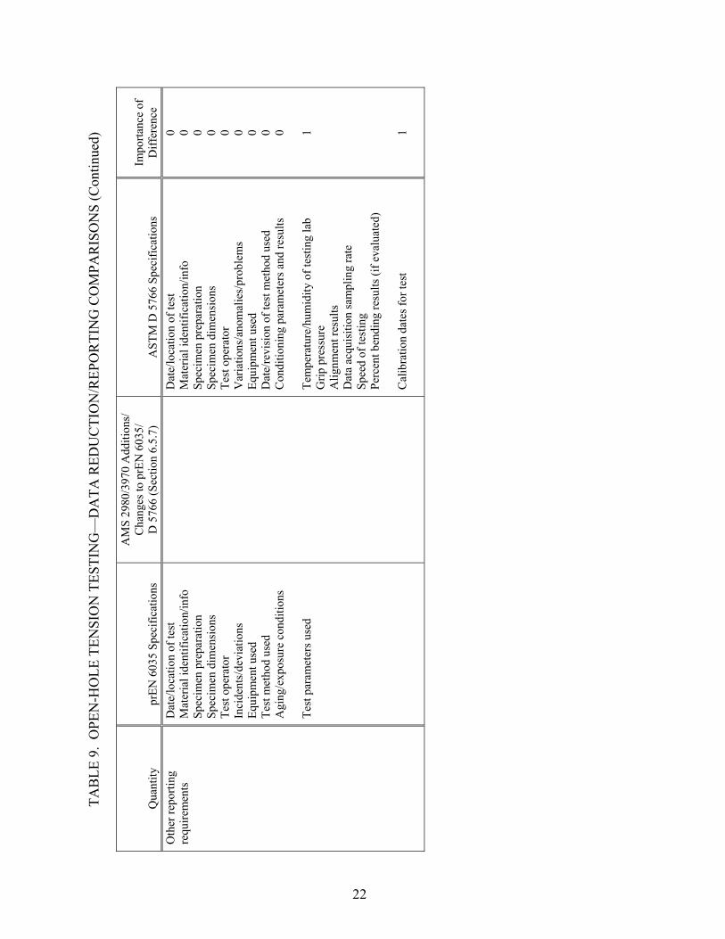
TAB
LE 9
. O
PEN
-HO
LE T
ENSI
ON
TES
TIN
G—
DA
TA R
EDU
CTI
ON
/REP
OR
TIN
G C
OM
PAR
ISO
NS
(Con
tinue
d)
Qua
ntity
pr
EN 6
035
Spec
ifica
tions
AM
S 29
80/3
970
Add
ition
s/
Cha
nges
to p
rEN
603
5/
D 5
766
(Sec
tion
6.5.
7)
AST
M D
576
6 Sp
ecifi
catio
ns
Impo
rtanc
e of
D
iffer
ence
O
ther
repo
rting
re
quire
men
ts
Dat
e/lo
catio
n of
test
M
ater
ial i
dent
ifica
tion/
info
Sp
ecim
en p
repa
ratio
n Sp
ecim
en d
imen
sion
s Te
st o
pera
tor
Inci
dent
s/de
viat
ions
Eq
uipm
ent u
sed
Test
met
hod
used
A
ging
/exp
osur
e co
nditi
ons
Test
par
amet
ers u
sed
D
ate/
loca
tion
of te
st
Mat
eria
l ide
ntifi
catio
n/in
fo
Spec
imen
pre
para
tion
Spec
imen
dim
ensi
ons
Test
ope
rato
r V
aria
tions
/ano
mal
ies/
prob
lem
s Eq
uipm
ent u
sed
Dat
e/re
visi
on o
f tes
t met
hod
used
C
ondi
tioni
ng p
aram
eter
s and
resu
lts
Tem
pera
ture
/hum
idity
of t
estin
g la
b
Grip
pre
ssur
e A
lignm
ent r
esul
ts
Dat
a ac
quis
ition
sam
plin
g ra
te
Spee
d of
test
ing
Perc
ent b
endi
ng re
sults
(if e
valu
ated
) C
alib
ratio
n da
tes f
or te
st
0 0 0 0 0 0 0 0 0 1 1
22

2.4 LAMINA COMPRESSION TESTING.
The two test methods considered, prEN 2850-B and SACMA SRM 1 R-94, are similar test methods for determining compressive properties of composite materials (tables 10 through 12). This type of compression test, sometimes referred to as a modified ASTM D 695 compression test, features an end-loaded, face-supported specimen. Whereas untabbed specimens are used for modulus determinations, tabbed specimens are used for strength determination. Note that prEN 2850-B describes two types of compression tests; this comparison is based on method B. The AMS 2980 and 3970 specifications provide additions and changes only to prEN 2850-B; the SACMA SRM 1 standard is not referred to in either AMS specification. A comparison of specimen geometries revealed several minor differences in dimensions and tolerances that are not expected to produce significant effects on results. Some confusion exists concerning the specification of specimen gage lengths, however. Whereas similar gage lengths are listed for the prEN 2850-B and SACMA SRM 1 test methods (5 mm versus 4.75 mm, respectively), the AMS 2980 and 3970 specifications, which modify the prEN 2850-B test method, specify a 12.5-mm gage length. It is possible that this significantly larger gage length given in the AMS 2980 and 3970 specifications refers to a different quantity. The shorter gage lengths specified in both the prEN 2850-B and SACMA SRM 1 test methods are clearly shown as the length of the untabbed region of the specimen used for strength determination. The opening in the face support, or cover plate, used for untabbed specimens during modulus determination is shown as 12.7 mm in length in the SACMA SRM 1 test method. Since the 12.5-mm gage length is simply stated in the AMS 2980 and 3970 specifications without referring to a drawing, it is not clear whether this dimension refers to the tabbed or the untabbed specimen configurations. However, this 12.5-mm dimension is believed to refer to the length of the opening in the face support in the modulus specimens. Whereas both prEN 2850-B and SACMA SRM 1 specify a minimum of five specimens, the AMS 2980 and 3970 specifications require six specimens. Different data ranges for calculating the modulus of elasticity between prEN 2850-B and SACMA SRM 1 may produce minimal effects on results.
23

TAB
LE 1
0. L
AM
INA
CO
MPR
ESSI
ON
TES
TIN
G (W
AR
P/W
EFT)
—SP
ECIM
EN G
EOM
ETR
IC C
OM
PAR
ISO
NS
Prop
erty
pr
EN 2
850-
B S
peci
ficat
ions
AM
S 29
80/3
970
Add
ition
s/
Cha
nges
to p
rEN
285
0-B
(S
ectio
n 6.
5.3)
SA
CM
A S
RM
1R
-94
Spec
ifica
tions
Im
porta
nce
of
Diff
eren
ce
Lam
inat
e la
y-up
U
nidi
rect
iona
l lam
inat
es
Fabr
ics
[(90
/0)]
6S (C
ompr
essi
ve W
eft)
(AM
S 29
80-2
) [(
90/0
)]6S
(Com
pres
sive
Wef
t) [(
0/90
)]6S
(Com
pres
sive
War
p)
(AM
S 39
70-2
)
Uni
dire
ctio
nal l
amin
ates
Fa
bric
s 1
Ove
rall
spec
imen
le
ngth
75
to 8
0 m
m
80
mm
±0.
1 m
m
1
Spec
imen
gag
e le
ngth
5
mm
(dis
tanc
e be
twee
n ta
bs in
sp
ecim
ens u
sed
for s
treng
th
dete
rmin
atio
n)
12.5
mm
(ope
ning
in th
e fa
ce
supp
ort f
or sp
ecim
ens u
sed
for
mod
ulus
det
erm
inat
ion?
)
4.75
mm
(dis
tanc
e be
twee
n ta
bs in
sp
ecim
ens u
sed
for s
treng
th
dete
rmin
atio
n)
2-3
Spec
imen
gag
e le
ngth
to
lera
nce
±0.5
/-0 m
m
±0
.1 m
m
1
Spec
imen
wid
th
12.5
mm
15.0
mm
1
Spec
imen
wid
th
tole
ranc
e • •
±0.2
mm
0.
05-m
m si
de-to
-sid
e pa
ralle
lism
±0
.1 m
m
1
Spec
imen
thic
knes
s N
ot sp
ecifi
ed
• •
Uni
dire
ctio
nal m
ater
ials
: 1.0
2-m
m
nom
inal
thic
knes
s Fa
bric
spec
imen
s: 3
.05-
mm
nom
inal
th
ickn
ess
1
Use
of t
abs
• • •
• •
Unt
abbe
d sp
ecim
en fo
r m
odul
us m
easu
rem
ent
Tabb
ed sp
ecim
en fo
r stre
ngth
m
easu
rem
ent
Eith
er b
onde
d or
inte
gral
tabs
U
ntab
bed
spec
imen
for m
odul
us
mea
sure
men
t Ta
bbed
spec
imen
for s
treng
th
mea
sure
men
t
0
Tab
mat
eria
l R
ecom
men
ds u
sing
the
sam
e m
ater
ial a
s the
spec
imen
Com
posi
te m
ater
ial i
n a
0/90
or
ient
atio
n (f
abric
or t
ape)
1
24
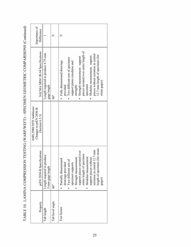
TAB
LE 1
0. L
AM
INA
CO
MPR
ESSI
ON
TES
TIN
G (W
AR
P/W
EFT)
—SP
ECIM
EN G
EOM
ETR
IC C
OM
PAR
ISO
NS
(Con
tinue
d)
Prop
erty
pr
EN 2
850-
B S
peci
ficat
ions
AM
S 29
80/3
970
Add
ition
s/
Cha
nges
to p
rEN
285
0-B
(S
ectio
n 6.
5.3)
SA
CM
A S
RM
1R
-94
Spec
ifica
tions
Im
porta
nce
of
Diff
eren
ce
Tab
leng
th
Leng
th re
quire
d to
pro
duce
5-
mm
gag
e le
ngth
Leng
th re
quire
d to
pro
duce
4.7
5-m
m
gage
leng
th
1
Tab
beve
l ang
le
90°
90
° 0
Test
fixt
ure
• • • •
• • • •
Parti
ally
dim
ensi
oned
dr
awin
gs p
rovi
ded
Two
diff
eren
t set
s of
spec
imen
supp
orts
St
reng
th m
easu
rem
ent:
su
ppor
t pie
ces s
erra
ted
over
en
tire
leng
th o
f spe
cim
en
Mod
ulus
mea
sure
men
t:
supp
ort p
iece
s with
out
serr
atio
n in
cen
tral 1
2.7-
mm
le
ngth
of s
peci
men
(for
stra
in
gage
s)
Fu
lly d
imen
sion
ed d
raw
ings
pr
ovid
ed
Two
diff
eren
t set
s of s
peci
men
su
ppor
t pla
tes (
mod
ulus
and
st
reng
th)
Stre
ngth
mea
sure
men
t: su
ppor
t pi
eces
serr
ated
ove
r ent
ire le
ngth
of
spec
imen
M
odul
us m
easu
rem
ent:
supp
ort
piec
es w
ithou
t ser
ratio
n in
cen
tral
12.7
-mm
leng
th o
f spe
cim
en (f
or
stra
in g
ages
)
0
25

TAB
LE 1
1. L
AM
INA
CO
MPR
ESSI
ON
TES
TIN
G (W
AR
P/W
EFT)
—TE
ST P
RO
CED
UR
E C
OM
PAR
ISO
NS
Proc
edur
e pr
EN 2
850-
B S
peci
ficat
ions
AM
S 29
80/3
970
Add
ition
s/
Cha
nges
to p
rEN
285
0-B
(S
ectio
n 6.
5.3)
SA
CM
A S
RM
1R
-94
Spec
ifica
tions
Im
porta
nce
of
Diff
eren
ce
Load
indi
cato
r A
ccur
ate
to w
ithin
1%
of t
he
load
rang
e us
ed
A
s def
ined
by
AST
M E
4
1
Spec
imen
alig
nmen
t In
ord
er to
avo
id b
uckl
ing,
an
accu
rate
alig
nmen
t sha
ll be
en
sure
d in
a su
itabl
e w
ay
Bac
k-to
-bac
k st
rain
gag
e m
easu
rem
ents
shal
l be
obta
ined
on
the
first
spec
imen
for e
ach
test
con
ditio
n
Not
add
ress
ed
1
Test
spee
d 1
mm
/min
1 m
m/m
in
0
Sam
plin
g Fi
ve sp
ecim
ens
Six
spec
imen
s (A
MS
2980
-2
and
AM
S 39
70-2
) A
t lea
st fi
ve sp
ecim
ens
2
Stra
in m
easu
rem
ent
Stra
in g
ages
acc
urat
e to
with
in
1% in
the
stra
in ra
nge
used
• • •
Stra
in g
age
or su
itabl
e co
mpr
esso
met
er
Stra
in g
age
shou
ld b
e 3
mm
or l
ess
Bac
k-to
-bac
k st
rain
gag
es a
rea
reco
mm
ende
d to
che
ck fo
r ben
ding
1
Mea
sure
men
t of
spec
imen
wid
th
• •
• •
Flat
-fac
ed m
icro
met
er
accu
rate
to 0
.01
mm
M
easu
re in
the
gage
leng
th
Fl
at-f
ace
mic
rom
eter
suita
ble
for
read
ing
0.03
-mm
acc
urac
y
Mea
sure
to w
ithin
0.0
1 m
m a
t se
vera
l poi
nts
1
Mea
sure
men
t of
spec
imen
thic
knes
s • • •
• •
Flat
-fac
ed m
icro
met
er
accu
rate
to 0
.01
mm
M
easu
re tw
ice
in th
e ga
ge
leng
th
Use
ave
rage
of t
wo
mea
sure
men
ts
D
oubl
e-ba
ll m
icro
met
er su
itabl
e fo
r re
adin
g 0.
03-m
m a
ccur
acy
M
easu
re to
with
in 0
.01
mm
at
seve
ral p
oint
s
1
Test
fixt
ure
bolt
torq
ue
App
ly a
grip
ping
load
of
0.5
Nm
Fi
rst t
orqu
e al
l bol
ts
sequ
entia
lly to
a lo
w to
rque
, th
en in
crea
se se
quen
tially
to
the
spec
ified
torq
ue
0.7
to 1
.0 N
m
1
26

TAB
LE 1
2. L
AM
INA
CO
MPR
ESSI
ON
TES
TIN
G (W
AR
P/W
EFT)
—D
ATA
RED
UC
TIO
N/R
EPO
RTI
NG
CO
MPA
RIS
ON
S
Qua
ntity
pr
EN 2
850-
B S
peci
ficat
ions
AM
S 29
80/3
970
Add
ition
s/
Cha
nges
to p
rEN
285
0-B
(S
ectio
n 6.
5.3)
SA
CM
A S
RM
1R
-94
Spec
ifica
tions
Im
porta
nce
of
Diff
eren
ce
Spec
imen
are
a, A
W
idth
mea
sure
men
ts ti
mes
av
erag
e of
two
thic
knes
s m
easu
rem
ents
A
vera
ge w
idth
mea
sure
men
ts ti
mes
av
erag
e th
ickn
ess m
easu
rem
ents
1
Ulti
mat
e co
mpr
essi
ve
stre
ngth
U
se a
vera
ge a
rea
for e
ach
spec
imen
Use
ave
rage
are
a fo
r eac
h sp
ecim
en
Rep
ort t
o th
ree
sign
ifica
nt fi
gure
s 0
Com
pres
sion
mod
ulus
of
ela
stic
ity
Seca
nt m
odul
us m
easu
red
betw
een
10%
and
50%
of f
ailu
re
load
Mod
ulus
refe
renc
e po
ints
: 10
00-3
000
µε
Seca
nt m
odul
us b
etw
een
1000
-300
0 µε
R
epor
t to
thre
e si
gnifi
cant
figu
res
2
Failu
re m
ode
Test
is o
nly
valid
if fa
ilure
occ
urs
in th
e fr
ee le
ngth
of t
he te
st p
iece
. Th
ere
shal
l be
no b
ushi
ng o
f the
en
ds.
Com
pres
sion
failu
re w
ithin
the
gage
leng
th in
clud
ing
thro
ugh
thic
knes
s she
ar, b
room
ing,
tra
nsve
rse
shea
r, or
split
ting
Ret
est s
peci
men
s tha
t bre
ak a
t som
e ob
viou
s fla
ws o
r at t
ab d
ebon
ds, o
r fa
ilure
with
in th
e ta
b ar
ea
1
Stat
istic
s In
divi
dual
val
ues,
arith
met
icm
eans
, and
stan
dard
dev
iatio
ns
Indi
vidu
al v
alue
s, av
erag
e va
lue,
st
anda
rd d
evia
tion,
and
coe
ffic
ient
of
varia
tion
1
Oth
er re
porti
ng
requ
irem
ents
• • • • • • •
• • • • • • • • • • •
Mat
eria
l ide
ntifi
catio
n/in
fo
Spec
imen
pre
para
tion
Spec
imen
dim
ensi
ons
Inci
dent
s/de
viat
ions
Te
st m
etho
d us
ed
Agi
ng/e
xpos
ure
cond
ition
s
Load
vs t
ime,
dis
p. o
r stra
in
diag
ram
M
ater
ial i
dent
ifica
tion/
info
Sp
ecim
en p
repa
ratio
n Sp
ecim
en d
imen
sion
s D
evia
tions
from
test
met
hod
Test
met
hod
used
Pr
etes
t con
ditio
ning
his
tory
R
elat
ive
hum
idity
/tem
pera
ture
co
nditi
ons
D
ate/
loca
tion
of te
st
Test
ope
rato
r St
rain
gag
e or
com
pres
som
eter
Fi
ber v
olum
e fo
r eac
h sp
ecim
en
0 0 0 0 0 0 0 0 1 1 1 1 1
27

2.5 LAMINATE COMPRESSION TESTING.
The laminate compression test method referred to in the AMS 2980 and 3970 specifications is the SACMA SRM 3-94 open-hole compression test method, but using a specimen without a hole (tables 13 through 15). Since the resulting test method is not similar to any ASTM compression tests without holes, a comparison is made to ASTM D 6484 using a specimen without a central hole. This test method is very similar to SACMA SRM 3 and therefore provides for a good comparison. Note, however, that the AMS 2980 and 3970 specifications provide additions and changes only to SACMA SRM 3; the ASTM D 6484 standard is not referred to in either AMS specification. A comparison of specimen geometries and tolerances revealed only minor differences, none of which are expected to produce significant effects on results. AMS 2980 and 3970 require six specimens, whereas both SACMA SRM 3 and ASTM D 6484 specify a minimum of five specimens. Whereas strain measurement methods differ between SACMA SRM 3 and ASTM D 6484, both are intended for testing an open-hole specimen, and thus the comparison is of limited significance when used for unnotched compression testing. Although the test fixture specified in the two test methods is very similar, the method of load introduction differs significantly. Whereas ASTM D 6484 requires hydraulic wedge grips to be used to grip the test fixture, the SACMA SRM 3 test method allows the test fixture to be end-loaded between two parallel platens of the test machine.
28

TAB
LE 1
3. L
AM
INA
TE C
OM
PRES
SIO
N T
ESTI
NG
—SP
ECIM
EN/F
IXTU
RE
GEO
MET
RIC
CO
MPA
RIS
ON
S
Prop
erty
SAC
MA
SR
M 3
199
4 Sp
ecifi
catio
ns
(With
out h
ole)
AM
S 29
80/3
970
Add
ition
s/
Cha
nges
to S
AC
MA
SR
M 3
(S
ectio
n 6.
5.8)
A
STM
D 6
484
Spec
ifica
tions
(W
ithou
t hol
e)
Impo
rtanc
e of
D
iffer
ence
La
min
ate
lay-
up
[(+4
5/0)
/(-45
/90)
] 2S f
or
unid
irect
iona
l tap
es
[(+4
5/0)
/(-45
/90)
] NS
for
fabr
ics (
~2.5
mm
thic
knes
s)
[(0/
90)/(
45/-4
5)] 3S
(A
MS
2980
-2)
[(45
/-45)
/(0/9
0)/(-
45/4
5)/(9
0/0)
] 2S
(AM
S 39
70-2
)
Mul
tidire
ctio
nal f
iber
orie
ntat
ions
(m
inim
um o
f tw
o di
rect
ions
) and
bal
ance
d an
d sy
mm
etric
stac
king
sequ
ence
s. 3
- to
5-m
m p
erm
issi
ble
thic
knes
s ran
ge.
1
Ove
rall
spec
imen
le
ngth
30
5 m
m
30
0 ±0
.25
mm
1
Spec
imen
wid
th
38.1
mm
36 m
m
1
Spec
imen
wid
th
tole
ranc
e ±
0.1
mm
±0.2
5 m
m
1
Spec
imen
thic
knes
s • •
Tape
s: 1
6-pl
y qu
asi-
isot
ropi
c
Fabr
ic:
2.5-
mm
nom
inal
th
ickn
ess h
avin
g qu
asi-
isot
ropi
c or
ient
atio
n
4-
mm
nom
inal
thic
knes
s Pe
rmis
sibl
e ra
nge
of 3
-5 m
m
1
Rat
io o
f ung
rippe
d sp
ecim
en le
ngth
to
spec
imen
wid
th
•
Not
spec
ified
; bas
ed o
n fix
ture
/spe
cim
en
dim
ensi
ons
2.7
1
Supp
ort f
ixtu
re
• • •
• • • • •
Face
supp
orts
spec
imen
Lo
ng g
rip/s
hort
grip
as
sem
bly
with
supp
ort
plat
es
Cut
out o
n bo
th fa
ces o
f fix
ture
Fa
ce su
ppor
ts sp
ecim
en
Long
grip
/sho
rt gr
ip a
ssem
bly
with
su
ppor
t pla
tes
Cut
out o
n bo
th fa
ces o
f fix
ture
Th
erm
al-s
pray
ed sp
ecim
en g
rippi
ng
area
s St
ainl
ess s
teel
shim
s to
mai
ntai
n a
0.00
- to
0.1
2-m
m to
lera
nce
gap
betw
een
supp
ort p
late
s and
long
grip
0 0 0 NC
NC
29
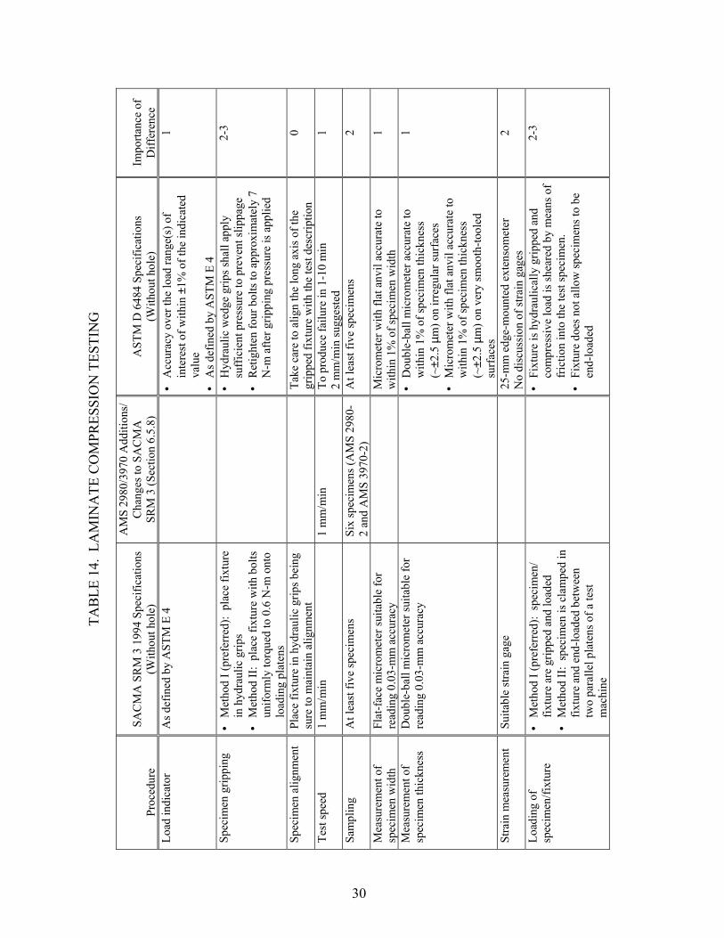
TAB
LE 1
4. L
AM
INA
TE C
OM
PRES
SIO
N T
ESTI
NG
Proc
edur
e SA
CM
A S
RM
3 1
994
Spec
ifica
tions
(With
out h
ole)
AM
S 29
80/3
970
Add
ition
s/
Cha
nges
to S
AC
MA
SR
M 3
(Sec
tion
6.5.
8)
AST
M D
648
4 Sp
ecifi
catio
ns
(With
out h
ole)
Im
porta
nce
of
Diff
eren
ce
Load
indi
cato
r A
s def
ined
by
AST
M E
4
• •
Acc
urac
y ov
er th
e lo
ad ra
nge(
s) o
f in
tere
st o
f with
in ±
1% o
f the
indi
cate
d va
lue
As d
efin
ed b
y A
STM
E 4
1
Spec
imen
grip
ping
• •
• •
Met
hod
I (pr
efer
red)
: pl
ace
fixtu
re
in h
ydra
ulic
grip
s M
etho
d II
: pl
ace
fixtu
re w
ith b
olts
un
iform
ly to
rque
d to
0.6
N-m
ont
o lo
adin
g pl
aten
s
H
ydra
ulic
wed
ge g
rips s
hall
appl
y su
ffic
ient
pre
ssur
e to
pre
vent
slip
page
R
etig
hten
four
bol
ts to
app
roxi
mat
ely
7 N
-m a
fter g
rippi
ng p
ress
ure
is a
pplie
d
2-3
Spec
imen
alig
nmen
t Pl
ace
fixtu
re in
hyd
raul
ic g
rips b
eing
su
re to
mai
ntai
n al
ignm
ent
Ta
ke c
are
to a
lign
the
long
axi
s of t
he
grip
ped
fixtu
re w
ith th
e te
st d
escr
iptio
n 0
Test
spee
d 1
mm
/min
1
mm
/min
To
pro
duce
failu
re in
1-1
0 m
in
2 m
m/m
in su
gges
ted
1
Sam
plin
g A
t lea
st fi
ve sp
ecim
ens
Six
spec
imen
s (A
MS
2980
-2
and
AM
S 39
70-2
) A
t lea
st fi
ve sp
ecim
ens
2
Mea
sure
men
t of
spec
imen
wid
th
Flat
-fac
e m
icro
met
er su
itabl
e fo
r re
adin
g 0.
03-m
m a
ccur
acy
M
icro
met
er w
ith fl
at a
nvil
accu
rate
to
with
in 1
% o
f spe
cim
en w
idth
1
Mea
sure
men
t of
spec
imen
thic
knes
s D
oubl
e-ba
ll m
icro
met
er su
itabl
e fo
r re
adin
g 0.
03-m
m a
ccur
acy
• D
oubl
e-ba
ll m
icro
met
er a
ccur
ate
to
with
in 1
% o
f spe
cim
en th
ickn
ess
(~±2
.5 µ
m) o
n irr
egul
ar su
rfac
es
• M
icro
met
er w
ith fl
at a
nvil
accu
rate
to
with
in 1
% o
f spe
cim
en th
ickn
ess
(~±2
.5 µ
m) o
n ve
ry sm
ooth
-tool
ed
surf
aces
1
Stra
in m
easu
rem
ent
Suita
ble
stra
in g
age
25-m
m e
dge-
mou
nted
ext
enso
met
er
No
disc
ussi
on o
f stra
in g
ages
2
Load
ing
of
spec
imen
/fixt
ure
• • •
Met
hod
I (pr
efer
red)
: sp
ecim
en/
fixtu
re a
re g
rippe
d an
d lo
aded
M
etho
d II
: sp
ecim
en is
cla
mpe
d in
fix
ture
and
end
-load
ed b
etw
een
two
para
llel p
late
ns o
f a te
st
mac
hine
•
Fixt
ure
is h
ydra
ulic
ally
grip
ped
and
com
pres
sive
load
is sh
eare
d by
mea
ns o
f fr
ictio
n in
to th
e te
st sp
ecim
en.
Fixt
ure
does
not
allo
w sp
ecim
ens t
o be
en
d-lo
aded
2-3
30

TAB
LE 1
5. L
AM
INA
TE C
OM
PRES
SIO
N T
ESTI
NG
—D
ATA
RED
UC
TIO
N/R
EPO
RTI
NG
CO
MPA
RIS
ON
S
Qua
ntity
SAC
MA
SR
M 3
199
4 Sp
ecifi
catio
ns
(With
out h
ole)
AM
S 29
80/3
970
Add
ition
s/
Cha
nges
to S
AC
MA
SR
M 3
(S
ectio
n 6.
5.8)
A
STM
D 6
484
Spec
ifica
tions
(W
ithou
t hol
e)
Impo
rtanc
e of
D
iffer
ence
Sp
ecim
en a
rea,
A
Bas
ed o
n av
erag
e sp
ecim
en
thic
knes
s and
wid
th
W
idth
tim
es th
ickn
ess
1
Ulti
mat
e co
mpr
essi
ve
stre
ngth
R
epor
t to
thre
e si
gnifi
cant
figu
res
R
epor
t to
thre
e si
gnifi
cant
figu
res
0
Ulti
mat
e co
mpr
essi
ve
stra
in
• •
For l
inea
r ela
stic
resp
onse
: ca
lcul
ate
usin
g ul
timat
e st
ress
an
d m
odul
us
For n
onlin
ear b
ehav
ior,
read
st
rain
dire
ctly
Mea
sure
and
repo
rt fa
ilure
st
rain
N
ot a
ddre
ssed
N
C
Com
pres
sive
mod
ulus
of
ela
stic
ity
• • Se
cant
mod
ulus
M
odul
us re
fere
nce
poin
ts:
1000
-300
0 µε
Mod
ulus
refe
renc
e po
ints
: 10
00-3
000
µε
Not
add
ress
ed
NC
Failu
re m
ode
• •
Ret
ests
shal
l be
perf
orm
ed fo
r sp
ecim
ens t
hat b
reak
at s
ome
obvi
ous f
law
Id
entif
y fa
ilure
mod
e an
d lo
catio
n
Com
pres
sion
failu
re w
ithin
the
ga
ge le
ngth
incl
udin
g th
roug
h
thic
knes
s she
ar, b
room
ing,
or
trans
vers
e sh
ear
Thre
e-pl
ace
failu
re m
ode
desc
ripto
r de
velo
ped
for s
peci
men
with
hol
e, n
ot
appl
icab
le fo
r spe
cim
en w
ithou
t hol
e
2
Stat
istic
s
In
divi
dual
val
ues,
mea
n(a
vera
ge) v
alue
, sta
ndar
d de
viat
ion,
and
coe
ffic
ient
of
varia
tion
for p
rope
rties
de
term
ined
In
divi
dual
val
ues,
mea
n (a
vera
ge) v
alue
, st
anda
rd d
evia
tion,
and
coe
ffic
ient
of
varia
tion
for p
rope
rties
det
erm
ined
0
31
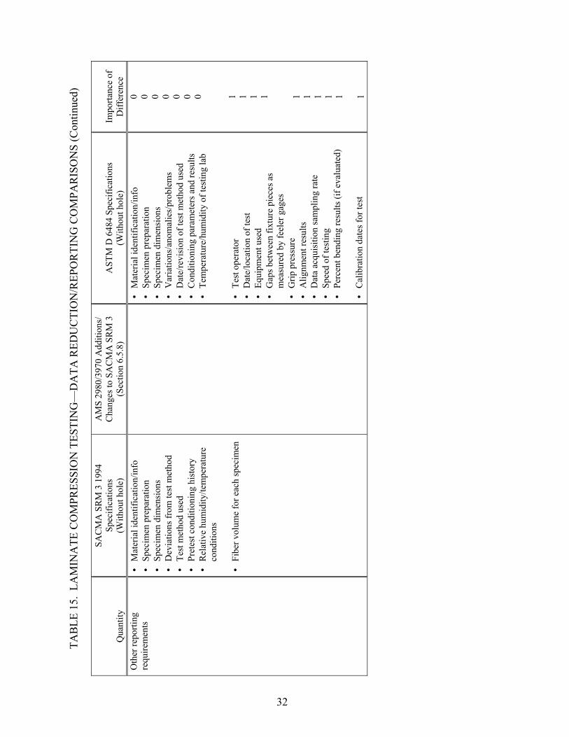
TAB
LE 1
5. L
AM
INA
TE C
OM
PRES
SIO
N T
ESTI
NG
—D
ATA
RED
UC
TIO
N/R
EPO
RTI
NG
CO
MPA
RIS
ON
S (C
ontin
ued)
Qua
ntity
SAC
MA
SR
M 3
199
4 Sp
ecifi
catio
ns
(With
out h
ole)
AM
S 29
80/3
970
Add
ition
s/
Cha
nges
to S
AC
MA
SR
M 3
(S
ectio
n 6.
5.8)
A
STM
D 6
484
Spec
ifica
tions
(W
ithou
t hol
e)
Impo
rtanc
e of
D
iffer
ence
O
ther
repo
rting
re
quire
men
ts
• • • • • • • •
• • • • • • • • • • • • • • • • •
Mat
eria
l ide
ntifi
catio
n/in
fo
Spec
imen
pre
para
tion
Spec
imen
dim
ensi
ons
Dev
iatio
ns fr
om te
st m
etho
d Te
st m
etho
d us
ed
Pret
est c
ondi
tioni
ng h
isto
ry
Rel
ativ
e hu
mid
ity/te
mpe
ratu
re
cond
ition
s
Fibe
r vol
ume
for e
ach
spec
imen
M
ater
ial i
dent
ifica
tion/
info
Sp
ecim
en p
repa
ratio
n Sp
ecim
en d
imen
sion
s V
aria
tions
/ano
mal
ies/
prob
lem
s D
ate/
revi
sion
of t
est m
etho
d us
ed
Con
ditio
ning
par
amet
ers a
nd re
sults
Te
mpe
ratu
re/h
umid
ity o
f tes
ting
lab
Te
st o
pera
tor
Dat
e/lo
catio
n of
test
Eq
uipm
ent u
sed
Gap
s bet
wee
n fix
ture
pie
ces a
s m
easu
red
by fe
eler
gag
es
Grip
pre
ssur
e A
lignm
ent r
esul
ts
Dat
a ac
quis
ition
sam
plin
g ra
te
Spee
d of
test
ing
Perc
ent b
endi
ng re
sults
(if e
valu
ated
)
Cal
ibra
tion
date
s for
test
0 0 0 0 0 0 0 1 1 1 1 1 1 1 1 1 1
32

2.6 OPEN-HOLE COMPRESSION TESTING.
Although only the SACMA SRM 3-94 open-hole compression test method is referred to in the AMS 2980 and 3970 specifications, a comparison is made to ASTM D 6484, a similar open-hole compression test method (tables 16 through 18). Therefore, this comparison parallels that performed for laminate compression testing, which followed these test methods using a specimen without a hole. In addition to the differences noted in the laminate compression comparison, a few additional differences exist related to the hole in the specimen. Although both the specimen width and the hole diameter are approximately 5% different between the two test methods, the ratio of specimen width to hole diameter remains the same (6.0). Whereas guidance for hole preparation is provided in ASTM D6485, the SACMA test method simply states that the “hole must not have delamination or other damage.” The difference in the fixture-gripping method (required use of hydraulic grips in ASTM D 6484 versus the permitted use of end-loading in SACMA SRM 3) is perceived to be of lesser importance for open-hole compression testing than for laminate compression testing (no hole), since failures must occur at the location of the hole to be acceptable.
33

TAB
LE 1
6. O
PEN
-HO
LE C
OM
PRES
SIO
N T
ESTI
NG
—SP
ECIM
EN/F
IXTU
RE
GEO
MET
RIC
CO
MPA
RIS
ON
S
Prop
erty
SA
CM
A S
RM
3 1
994
Spec
ifica
tions
AM
S 29
80/3
970
Add
ition
s/
Cha
nges
to S
AC
MA
SR
M 3
(S
ectio
n 6.
5.9)
A
STM
D 6
484
Spec
ifica
tions
Im
porta
nce
of
Diff
eren
ce
Lam
inat
e la
y-up
[(
+45/
0)/(-
45/9
0)] 2S
for
un
idire
ctio
nal t
apes
[(
+45/
0)/(-
45/9
0)] N
S fo
r fab
rics
(~2.
5 m
m th
ickn
ess)
[(0/
90)/(
45/-4
5)] 3S
(A
MS
2980
-2)
[(45
/-45)
/(0/9
0)/(-
45/4
5)/(9
0/0)
] 2S
(AM
S 39
70-2
)
• • •
Mul
tidire
ctio
nal f
iber
orie
ntat
ions
(m
inim
um o
f tw
o di
rect
ions
) B
alan
ced
and
sym
met
ric
3- to
5-m
m p
erm
issi
ble
thic
knes
s ran
ge
1
Ove
rall
spec
imen
le
ngth
30
5 m
m
30
0 ±0
.25
mm
1
Spec
imen
wid
th
38.1
mm
36 m
m
2
Spec
imen
wid
th
tole
ranc
e ±0
.1 m
m
±0
.25
mm
1
Spec
imen
thic
knes
s • •
Tape
s: 1
6-pl
y qu
asi-i
sotro
pic
Fa
bric
: 2.
5-m
m n
omin
al
thic
knes
s, qu
asi-i
sotro
pic
orie
ntat
ion
4-
mm
nom
inal
thic
knes
s Pe
rmis
sibl
e ra
nge
of 3
-5 m
m
1
Hol
e di
amet
er
6.35
mm
6.
35 m
m
6 m
m
2
Tole
ranc
e on
hol
e di
amet
er
±0.0
8 m
m in
text
±0
.12
mm
on
figur
e ±0
.09
mm
, -0.
0 m
m
±0.0
6 m
m
1
Rat
io o
f spe
cim
en
wid
th to
hol
e di
amet
er
6
60
34

TAB
LE 1
6. O
PEN
-HO
LE C
OM
PRES
SIO
N T
ESTI
NG
—SP
ECIM
EN/F
IXTU
RE
GEO
MET
RIC
CO
MPA
RIS
ON
S (C
ontin
ued)
Prop
erty
SA
CM
A S
RM
3 1
994
Sp
ecifi
catio
ns
AM
S 29
80/3
970
Add
ition
s/
Cha
nges
to S
AC
MA
SR
M 3
(S
ectio
n 6.
5.9)
A
STM
D 6
484
Spec
ifica
tions
Im
porta
nce
of
Diff
eren
ce
Supp
ort f
ixtu
re
• • •
• • • • •
Face
supp
orts
spec
imen
Lo
ng g
rip/s
hort
grip
ass
embl
y w
ith su
ppor
t pla
tes
Cut
out o
n bo
th fa
ces o
f fix
ture
Fa
ce su
ppor
ts sp
ecim
en
Long
grip
/sho
rt gr
ip a
ssem
bly
with
su
ppor
t pla
tes
Cut
out o
n bo
th fa
ces o
f fix
ture
Th
erm
al-s
pray
ed sp
ecim
en g
rippi
ng
area
s St
ainl
ess s
teel
shim
s to
mai
ntai
n a
0.00
- to
0.12
-mm
tole
ranc
e ga
p be
twee
n su
ppor
t pla
tes a
nd lo
ng g
rip
0 0 0 NC
NC
35

TAB
LE 1
7. O
PEN
-HO
LE C
OM
PRES
SIO
N T
ESTI
NG
—TE
ST P
RO
CED
UR
E C
OM
PAR
ISO
NS
Proc
edur
e SA
CM
A S
RM
3 1
994
Spec
ifica
tions
AM
S 29
80/3
970
Add
ition
s/
Cha
nges
to S
AC
MA
SR
M 3
(S
ectio
n 6.
5.9)
A
STM
D 6
484
Spec
ifica
tions
Im
porta
nce
of
Diff
eren
ce
Load
indi
cato
r A
s def
ined
by
AST
M E
4
• •
Acc
urac
y ov
er th
e lo
ad ra
nge(
s) o
f int
eres
t of
with
in ±
1% o
f the
indi
cate
d va
lue
As d
efin
ed b
y A
STM
E 4
1
Spec
imen
grip
ping
• •
• •
Met
hod
I (pr
efer
red)
: pl
ace
fixtu
re in
test
mac
hine
hy
drau
lic g
rips
Met
hod
II:
plac
e fix
ture
w
ith b
olts
uni
form
ly
torq
ued
to 0
.6 N
-m o
nto
load
ing
plat
ens
H
ydra
ulic
wed
ge g
rips s
hall
appl
y su
ffic
ient
late
ral p
ress
ure
to p
reve
nt
slip
page
bet
wee
n th
e gr
ip fa
ce a
nd th
e su
ppor
t fix
ture
R
etig
hten
four
bol
ts to
app
roxi
mat
ely
7 N
-m
afte
r hyd
raul
ic g
rippi
ng p
ress
ure
is
appl
ied
1
Spec
imen
alig
nmen
t Pl
ace
the
fixtu
re in
the
test
m
achi
ne h
ydra
ulic
grip
s bei
ng
sure
to m
aint
ain
alig
nmen
t
Ta
ke c
are
to a
lign
the
long
axi
s of t
he
grip
ped
fixtu
re w
ith th
e te
st d
escr
iptio
n 0
Test
spee
d 1
mm
/min
1
mm
/min
To
pro
duce
failu
re in
1-1
0 m
in
2 m
m/m
in su
gges
ted
1
Sam
plin
g A
t lea
st fi
ve sp
ecim
ens
Six
spec
imen
s (A
MS
2980
-2
and
AM
S 39
70-2
) A
t lea
st fi
ve sp
ecim
ens
2
Hol
e pr
epar
atio
n H
ole
mus
t not
hav
e de
lam
inat
ions
or o
ther
da
mag
e
H
oles
shou
ld b
e dr
illed
und
ersi
zed
and
ream
ed to
fina
l dim
ensi
ons.
Tak
e sp
ecia
l ca
re to
ens
ure
that
cre
atio
n of
the
hole
doe
s no
t del
amin
ate
or o
ther
wis
e da
mag
e th
e m
ater
ial s
urro
undi
ng th
e ho
le.
2
Spec
imen
con
ditio
ning
Fo
llow
ing
SAC
MA
SR
M 1
1
St
anda
rd la
bora
tory
atm
osph
ere:
23°
±3°
C
and
50%
±10
% re
lativ
e hu
mid
ity
Req
uire
s mai
ntai
ning
tem
pera
ture
to w
ithin
±3
°C a
nd re
lativ
e va
por l
evel
to w
ithin
±3%
1
36

TAB
LE 1
7. O
PEN
-HO
LE C
OM
PRES
SIO
N T
ESTI
NG
—TE
ST P
RO
CED
UR
E C
OM
PAR
ISO
NS
(Con
tinue
d)
Proc
edur
e SA
CM
A S
RM
3 1
994
Spec
ifica
tions
AM
S 29
80/3
970
Add
ition
s/
Cha
nges
to S
AC
MA
SR
M 3
(S
ectio
n 6.
5.9)
A
STM
D 6
484
Spec
ifica
tions
Im
porta
nce
of
Diff
eren
ce
Mea
sure
men
t of
spec
imen
wid
th
Flat
-fac
e m
icro
met
er su
itabl
e fo
r rea
ding
0.0
3-m
m a
ccur
acy
Mic
rom
eter
with
flat
anv
il ac
cura
te to
with
in
1% o
f spe
cim
en w
idth
(~±7
6 µm
) 1
Mea
sure
men
t of
spec
imen
thic
knes
s D
oubl
e-ba
ll m
icro
met
er
suita
ble
for r
eadi
ng 0
.03
mm
ac
cura
cy
• •
Mic
rom
eter
with
dou
ble-
ball
inte
rfac
e ac
cura
te to
with
in 1
% o
f spe
cim
en th
ickn
ess
(~±2
.5 µ
m) o
n irr
egul
ar su
rfac
es
Mic
rom
eter
with
flat
anv
il ac
cura
te to
with
in
1% o
f spe
cim
en th
ickn
ess (
~±2.
5 µm
) on
very
smoo
th-to
oled
surf
aces
1
Mea
sure
men
t of h
ole
diam
eter
N
ot a
ddre
ssed
Mic
rom
eter
or g
age
capa
ble
of d
eter
min
ing
the
hole
dia
met
er to
±0.
025
mm
N
C
Stra
in m
easu
rem
ent
Suita
ble
stra
in g
age
loca
ted
25 m
m fr
om th
e ce
nter
of t
he
circ
ular
hol
e
25
-mm
gag
e le
ngth
ext
enso
met
er
No
disc
ussi
on o
f stra
in g
ages
1
Load
ing
of
spec
imen
/fixt
ure
• •
• •
Met
hod
I (pr
efer
red)
: sp
ecim
en a
nd fi
xtur
e ar
e gr
ippe
d in
to p
lace
and
lo
aded
M
etho
d II
: sp
ecim
en is
cl
ampe
d in
the
fixtu
re a
nd
plac
e be
twee
n tw
o pa
ralle
l pl
aten
s of a
test
mac
hine
an
d en
d-lo
aded
Fi
xtur
e is
hyd
raul
ical
ly g
rippe
d an
d co
mpr
essi
ve lo
ad is
shea
red
by m
eans
of
fric
tion
into
the
test
spec
imen
Fi
xtur
e do
es n
ot a
llow
spec
imen
s to
be e
nd-
load
ed
1
37

TAB
LE 1
8. O
PEN
-HO
LE C
OM
PRES
SIO
N T
ESTI
NG
—D
ATA
RED
UC
TIO
N/R
EPO
RTI
NG
CO
MPA
RIS
ON
S
Qua
ntity
SA
CM
A S
RM
3 1
994
Spec
ifica
tions
AM
S 29
80/3
970
Add
ition
s/
Cha
nges
to S
AC
MA
SR
M 3
(S
ectio
n 6.
5.9)
A
STM
D 6
484
Spec
ifica
tions
Im
porta
nce
of
Diff
eren
ce
Spec
imen
are
a, A
G
ross
are
a m
easu
rem
ent b
ased
on
ave
rage
spec
imen
thic
knes
s an
d w
idth
G
ross
are
a m
easu
rem
ent (
wid
th ti
mes
th
ickn
ess)
in th
e vi
cini
ty o
f the
hol
e
1
Ulti
mat
e op
en-h
ole
com
pres
sive
stre
ngth
• •
Use
gro
ss a
rea
for e
ach
spec
imen
R
epor
t to
thre
e si
gnifi
cant
fig
ures
U
se g
ross
are
a fo
r eac
h sp
ecim
en
Rep
ort t
o th
ree
sign
ifica
nt fi
gure
s 0
Wid
th to
dia
met
er ra
tio
N
ot a
ddre
ssed
Cal
cula
te/re
port
the
actu
al w
idth
-to-
diam
eter
ratio
for e
ach
spec
imen
and
the
nom
inal
wid
th-to
-dia
met
er ra
tio u
sing
no
min
al v
alue
s
NC
Dia
met
er to
thic
knes
s ra
tio
Not
add
ress
ed
C
alcu
late
/repo
rt th
e ac
tual
dia
met
er-to
-th
ickn
ess r
atio
for e
ach
spec
imen
and
the
nom
inal
dia
met
er-to
-thic
knes
s rat
io
NC
Failu
re m
ode
Iden
tify
failu
re m
ode
and
lo
catio
n
Any
com
pres
sion
failu
re
thro
ugh
the
hole
is a
ccep
tabl
e
• •
Failu
res t
hat d
o no
t occ
ur a
t the
hol
e ar
e no
t acc
epta
ble
Use
thre
e-pl
ace
failu
re m
ode
desc
ripto
r
1
Stat
istic
s In
divi
dual
val
ues,
mea
n (a
vera
ge)
valu
e, st
anda
rd d
evia
tion,
and
co
effic
ient
of v
aria
tion
for
prop
ertie
s det
erm
ined
In
divi
dual
val
ues,
mea
n (a
vera
ge) v
alue
, st
anda
rd d
evia
tion,
and
coe
ffic
ient
of
varia
tion
for p
rope
rties
det
erm
ined
0
38

TAB
LE 1
8. O
PEN
-HO
LE C
OM
PRES
SIO
N T
ESTI
NG
—D
ATA
RED
UC
TIO
N/R
EPO
RTI
NG
CO
MPA
RIS
ON
S (C
ontin
ued)
Qua
ntity
SA
CM
A S
RM
3 1
994
Spec
ifica
tions
AM
S 29
80/3
970
Add
ition
s/
Cha
nges
to S
AC
MA
SR
M 3
(S
ectio
n 6.
5.9)
A
STM
D 6
484
Spec
ifica
tions
Im
porta
nce
of
Diff
eren
ce
Oth
er re
porti
ng
requ
irem
ents
• • • • • • • •
• • • • • • • • • • • • • • • • •
Mat
eria
l ide
ntifi
catio
n/in
fo
Spec
imen
pre
para
tion
Spec
imen
dim
ensi
ons
Dev
iatio
ns fr
om te
st m
etho
d Te
st m
etho
d us
ed
Pret
est c
ondi
tioni
ng h
isto
ry
Rel
ativ
e hu
mid
ity/te
mpe
ratu
re
cond
ition
s
Fibe
r vol
ume
for e
ach
spec
imen
M
ater
ial i
dent
ifica
tion/
info
Sp
ecim
en p
repa
ratio
n Sp
ecim
en d
imen
sion
s V
aria
tions
/ano
mal
ies/
prob
lem
s D
ate/
revi
sion
of t
est m
etho
d us
ed
Con
ditio
ning
par
amet
ers a
nd re
sults
Te
mpe
ratu
re/h
umid
ity o
f tes
ting
lab
Te
st o
pera
tor
Dat
e/lo
catio
n of
test
Eq
uipm
ent u
sed
Gap
s bet
wee
n fix
ture
pie
ces a
s m
easu
red
by fe
eler
gag
es
Grip
pre
ssur
e A
lignm
ent r
esul
ts
Dat
a ac
quis
ition
sam
plin
g ra
te
Spee
d of
test
ing
Perc
ent b
endi
ng re
sults
(if e
valu
ated
)
Cal
ibra
tion
date
s for
test
0 0 0 0 0 0 0 1 1 1 1 1 1 1 1 1 1
39
2.7 FILLED-HOLE COMPRESSION TESTING.
There are no specifications for filled-hole compression testing in either the AMS 2980 or 3970 specifications (tables 19 through 21). Nonetheless, a comparison was made between a CEN test method (prEN 6036) and an ASTM test method (ASTM D 6742) for filled-hole compression testing. Whereas prEN 6036 is a complete test method, ASTM D 6742 supplements the ASTM standard for open-hole compression testing (D 6484). The two test methods being compared are fundamentally different in the manner in which the specimen is gripped and loaded. Whereas prEN 6036 directly loads the specimen into grips (the use of tabs is optional), ASTM D 6742 uses the same support fixture used by ASTM D 6484. This test fixture supports the faces of the specimen, gripping over a 100-mm length at either end. In addition to the difference in the method of gripping and loading, the specimen width and hole size differ between the two test methods, and result in a significantly different ratio of specimen width to hole diameter. Additional differences in the tolerance of the hole diameter, the hole countersink, and the fastener specification are all believed to be between minimal and moderate significance.
40

TAB
LE 1
9. F
ILLE
D-H
OLE
CO
MPR
ESSI
ON
TES
TIN
G—
SPEC
IMEN
/FIX
TUR
E G
EOM
ETR
IC C
OM
PAR
ISO
NS
Prop
erty
pr
EN 6
036
Spec
ifica
tions
A
STM
D 6
742
Spec
ifica
tions
Im
porta
nce
of
Diff
eren
ce
Lam
inat
e la
y-up
Q
uasi
-isot
ropi
c or
dire
cted
lam
inat
es
Num
ber o
f lay
ers d
epen
dant
on
laye
r thi
ckne
ss
• •
Mul
tidire
ctio
nal f
iber
orie
ntat
ions
(min
imum
of t
wo
dire
ctio
ns) a
nd b
alan
ced
and
sym
met
ric st
acki
ng
sequ
ence
s 3-
to 5
-mm
per
mis
sibl
e th
ickn
ess r
ange
1
Ove
rall
spec
imen
leng
th
Dep
enda
nt o
n ta
b le
ngth
30
0 ±0
.25
mm
1
Spec
imen
gag
e le
ngth
30
±0.
2 m
m
Not
app
licab
le
1
Spec
imen
wid
th
30 m
m
36 m
m
2-3
Spec
imen
wid
th
tole
ranc
e ±0
.2 m
m
±0.2
5 m
m
1
Spec
imen
thic
knes
s • •
Tape
s: d
epen
ding
on
laye
r thi
ckne
ss
Fabr
ic:
quas
i-iso
tropi
c la
min
ate
with
thic
knes
s as
clos
e as
pos
sibl
e to
4 m
m
4-m
m n
omin
al th
ickn
ess
Perm
issi
ble
rang
e of
3-5
mm
0
Hol
e di
amet
er
6.35
mm
6
mm
2-
3
Tole
ranc
e on
hol
e di
amet
er
+0.0
9 m
m, -
0.0
mm
• • •
Bot
h th
e ho
le a
nd fa
sten
er d
iam
eter
s mus
t be
accu
rate
ly
mea
sure
d an
d re
cord
ed
Typi
cal a
eros
pace
tole
ranc
e on
fast
ener
hol
e cl
eara
nce:
+0
.075
/-0.0
00 µ
m
Smal
l cha
nges
in c
lear
ance
can
aff
ect f
ailu
re m
ode
and
stre
ngth
2-3
Hol
e co
unte
rsin
k 10
0° c
onic
al c
ount
ersi
nk
Dep
th n
ot a
ddre
ssed
• •
Pref
erre
d ra
tio o
f cou
nter
sunk
hea
d de
pth-
to-th
ickn
ess
ratio
is in
the
rang
e of
0.0
to 0
.7
Cou
nter
sink
flus
hnes
s will
aff
ect s
treng
th re
sults
and
mus
t be
acc
urat
ely
mea
sure
d an
d re
cord
ed
2-3
Rat
io o
f spe
cim
en w
idth
to
hol
e di
amet
er
4.72
6 2-
3
Rat
io o
f hol
e di
amet
er to
th
ickn
ess o
f spe
cim
en
Not
add
ress
ed
In th
e ra
nge
from
1.5
to 3
.0
NC
41

TAB
LE 1
9. F
ILLE
D-H
OLE
CO
MPR
ESSI
ON
TES
TIN
G—
SPEC
IMEN
/FIX
TUR
E G
EOM
ETR
IC C
OM
PAR
ISO
NS
(Con
tinue
d)
Prop
erty
pr
EN 6
036
Spec
ifica
tions
A
STM
D 6
742
Spec
ifica
tions
Im
porta
nce
of
Diff
eren
ce
Rat
io o
f ung
rippe
d sp
ecim
en le
ngth
to
spec
imen
wid
th
Not
add
ress
ed; b
ased
on
grip
/tab
dim
ensi
ons
2.7
NC
Fast
ener
NA
S 15
80 V
4T b
olt
MS2
1042
-L4
nut
Flat
AN
960
C41
6 W
ashe
r
• • •
Fast
ener
shal
l be
spec
ified
as a
n in
itial
test
par
amet
er a
nd
repo
rted
Nom
inal
fast
ener
dia
met
er sh
all b
e 6
mm
W
ashe
r typ
e, n
umbe
r, an
d lo
catio
ns sh
all b
e sp
ecifi
ed a
s an
initi
al te
st p
aram
eter
2-3
Use
of t
abs
• •
Opt
iona
l If
use
d, th
ey sh
all b
e st
rain
com
patib
le w
ith
com
posi
te b
eing
test
ed
Not
use
d N
C
Supp
ort f
ixtu
re
No
supp
ort f
ixtu
re; s
peci
men
load
ed d
irect
ly in
to g
rips
• • • • •
Face
supp
orts
spec
imen
Lo
ng g
rip/s
hort
grip
ass
embl
y w
ith su
ppor
t pla
tes
Cut
out o
n bo
th fa
ces o
f fix
ture
Th
erm
al-s
pray
ed sp
ecim
en g
rippi
ng a
reas
St
ainl
ess s
teel
shim
s to
mai
ntai
n a
0.00
- to
0.12
-mm
to
lera
nce
gap
betw
een
supp
ort p
late
s and
long
grip
3-4
42

TAB
LE 2
0. F
ILLE
D-H
OLE
CO
MPR
ESSI
ON
TES
TIN
G—
TEST
PR
OC
EDU
RE
CO
MPA
RIS
ON
S
Proc
edur
e pr
EN 6
036
Spec
ifica
tions
A
STM
D 6
742
Spec
ifica
tions
Im
porta
nce
of
Diff
eren
ce
Load
indi
cato
r A
ccur
ate
to w
ithin
1%
of t
he lo
ad ra
nge
used
• •
Acc
urac
y ov
er th
e lo
ad ra
nge(
s) o
f int
eres
t of w
ithin
±1%
of
the
indi
cate
d va
lue.
A
s def
ined
by
AST
M E
4
0
Spec
imen
grip
ping
Su
itabl
e gr
ips o
r use
d w
ith c
ompr
essi
on ji
g fe
atur
ing
a gr
ip a
nd m
ovem
ent a
lignm
ent s
yste
m
• •
Hyd
raul
ic w
edge
grip
s sha
ll ap
ply
suff
icie
nt la
tera
l pr
essu
re to
pre
vent
slip
page
bet
wee
n th
e gr
ip fa
ce a
nd th
e su
ppor
t fix
ture
R
etig
hten
four
bol
ts to
app
roxi
mat
ely
7 N
-m a
fter
hydr
aulic
grip
ping
pre
ssur
e is
app
lied
2-3
Spec
imen
alig
nmen
t Sp
ecim
en a
ligne
d w
ithin
1° a
nd c
ente
red
on m
achi
ne
axis
Ta
ke c
are
to a
lign
the
long
axi
s of t
he g
rippe
d fix
ture
with
th
e te
st d
escr
iptio
n 1
Test
spee
d 0.
5 m
m/m
in
To p
rodu
ce fa
ilure
in 1
-10
min
2
mm
/min
sugg
este
d 1
Sam
plin
g Fi
ve sp
ecim
ens
At l
east
five
spec
imen
s 0
Hol
e pr
epar
atio
n Sp
ecia
l pre
caut
ions
to b
e ta
ken
to e
nsur
e th
at n
o de
lam
inat
ions
occ
ur d
urin
g m
achi
ning
H
oles
shou
ld b
e dr
illed
und
ersi
zed
and
ream
ed to
fina
l di
men
sion
s
1
Spec
imen
con
ditio
ning
Sp
ecim
en st
orag
e an
d te
stin
g to
be
carr
ied
out a
t 23
° ±2°
C a
nd 5
0% ±
5% re
lativ
e hu
mid
ity
• •
Stan
dard
labo
rato
ry a
tmos
pher
e: 2
3° ±
3°C
and
50%
±1
0% re
lativ
e hu
mid
ity
Req
uire
s mai
ntai
ning
tem
pera
ture
to w
ithin
±3°
C a
nd
rela
tive
vapo
r lev
el to
with
in ±
3%
0
Mea
sure
men
t of
spec
imen
wid
th
Ver
nier
cal
iper
acc
urat
e to
nea
rest
0.1
mm
A
vera
ge o
f thr
ee m
easu
rem
ents
in g
age
sect
ion
Mic
rom
eter
with
flat
anv
il ac
cura
te to
with
in 1
% o
f sp
ecim
en w
idth
(~±7
6 µm
) 1
Mea
sure
men
t of
spec
imen
thic
knes
s Fl
at-f
ace
mic
rom
eter
acc
urat
e to
nea
rest
0.0
1 m
m
Ave
rage
of t
hree
mea
sure
men
ts in
gag
e se
ctio
n • •
Mic
rom
eter
with
dou
ble-
ball
inte
rfac
e ac
cura
te to
with
in
1% o
f spe
cim
en th
ickn
ess (
~±2.
5 µm
) on
irreg
ular
su
rfac
es
Mic
rom
eter
with
flat
anv
il ac
cura
te to
with
in 1
% o
f sp
ecim
en th
ickn
ess (
~±2.
5 µm
) on
very
smoo
th-to
oled
su
rfac
es
1
43

TAB
LE 2
0. F
ILLE
D-H
OLE
CO
MPR
ESSI
ON
TES
TIN
G—
TEST
PR
OC
EDU
RE
CO
MPA
RIS
ON
S (C
ontin
ued)
Proc
edur
e pr
EN 6
036
Spec
ifica
tions
A
STM
D 6
742
Spec
ifica
tions
Im
porta
nce
of
Diff
eren
ce
Mea
sure
men
t of h
ole
diam
eter
N
ot a
ddre
ssed
M
icro
met
er o
r gag
e ca
pabl
e of
det
erm
inin
g th
e ho
le
diam
eter
to ±
0.02
5 m
m
NC
Fast
ener
torq
ue
7 N
-m
Fast
ener
shal
l be
tight
ened
to th
e re
quire
d va
lue
usin
g a
calib
rate
d to
rque
wre
nch
1
Stra
in m
easu
rem
ent
Not
requ
ired
25-m
m g
age
leng
th e
xten
som
eter
N
o di
scus
sion
of s
train
gag
es
1
Load
ing
of
spec
imen
/fixt
ure
Spec
imen
load
ed d
irect
ly in
to g
rips
• •
Fixt
ure
is h
ydra
ulic
ally
grip
ped
and
com
pres
sive
load
is
shea
red
by m
eans
of f
rictio
n in
to th
e te
st sp
ecim
en
Fixt
ure
does
not
allo
w sp
ecim
ens t
o be
end
-load
ed
2-3
44

TAB
LE 2
1. F
ILLE
D-H
OLE
CO
MPR
ESSI
ON
TES
TIN
G—
DA
TA R
EDU
CTI
ON
/REP
OR
TIN
G C
OM
PAR
ISO
NS
Qua
ntity
pr
EN 6
036
Spec
ifica
tions
A
STM
D 6
742
Spec
ifica
tions
Im
porta
nce
of
Diff
eren
ce
Spec
imen
are
a, A
G
ross
are
a m
easu
rem
ent b
ased
on
aver
age
spec
imen
th
ickn
ess a
nd w
idth
G
ross
are
a m
easu
rem
ent (
wid
th ti
mes
thic
knes
s) in
the
vici
nity
of t
he h
ole
1
Ulti
mat
e fil
led-
hole
co
mpr
essi
ve st
reng
th
Use
gro
ss a
rea
for e
ach
spec
imen
U
se g
ross
are
a fo
r eac
h sp
ecim
en
Rep
ort t
o th
ree
sign
ifica
nt fi
gure
s 0
Nom
inal
fille
d-ho
le
com
pres
sive
stre
ngth
• •
Use
nom
inal
spec
imen
thic
knes
s as s
peci
fied
in
mat
eria
l spe
cific
atio
n U
se g
ross
spec
imen
wid
th
Not
add
ress
ed
NC
KT
Unn
otch
ed te
nsile
stre
ngth
div
ided
by
the
fille
d ho
le
tens
ile st
reng
th
Not
add
ress
ed
NC
Wid
th-to
-dia
met
er
ratio
Not
add
ress
ed
Cal
cula
te/re
port
the
actu
al w
idth
-to-d
iam
eter
ratio
for e
ach
spec
imen
and
the
nom
inal
wid
th-to
-dia
met
er ra
tio u
sing
no
min
al v
alue
s
NC
Dia
met
er-to
-thic
knes
s ra
tio
Not
add
ress
ed
Cal
cula
te/re
port
the
actu
al d
iam
eter
-to-th
ickn
ess r
atio
for
each
spec
imen
and
the
nom
inal
dia
met
er-to
-thic
knes
s rat
io
NC
Cou
nter
sink
dep
th-to
-th
ickn
ess r
atio
N
ot a
ddre
ssed
C
alcu
late
/repo
rt th
e ac
tual
cou
nter
sink
dep
th-to
-thic
knes
s ra
tio fo
r eac
h sp
ecim
en a
nd th
e no
min
al c
ount
ersi
nk d
epth
-to-
thic
knes
s rat
io
NC
Failu
re m
ode
Not
add
ress
ed
• •
Failu
res t
hat d
o no
t occ
ur a
t or n
ear t
he fa
sten
er h
ole
are
not a
ccep
tabl
e U
se th
ree-
plac
e fa
ilure
mod
e de
scrip
tor
NC
Stat
istic
s In
divi
dual
val
ues,
mea
n (a
vera
ge) v
alue
, and
st
anda
rd d
evia
tion
for p
rope
rties
det
erm
ined
In
divi
dual
val
ues,
aver
age
valu
e, st
anda
rd d
evia
tion,
and
co
effic
ient
of v
aria
tion
for p
rope
rties
det
erm
ined
1
45

TAB
LE 2
1. F
ILLE
D-H
OLE
CO
MPR
ESSI
ON
TES
TIN
G—
DA
TA R
EDU
CTI
ON
/REP
OR
TIN
G C
OM
PAR
ISO
NS
(Con
tinue
d)
Qua
ntity
pr
EN 6
036
Spec
ifica
tions
A
STM
D 6
742
Spec
ifica
tions
Im
porta
nce
of
Diff
eren
ce
Oth
er re
porti
ng
requ
irem
ents
M
ater
ial i
dent
ifica
tion/
info
Sp
ecim
en p
repa
ratio
n Sp
ecim
en d
imen
sion
s Te
st o
pera
tor
Inci
dent
s/de
viat
ions
D
ate/
loca
tion
of te
st
Test
met
hod
used
A
ging
/exp
osur
e co
nditi
ons
Tem
pera
ture
/hum
idity
of t
estin
g la
b Eq
uipm
ent u
sed
Test
par
amet
ers u
sed
• • • • • • • • • • • • • • • • • • • • •
Mat
eria
l ide
ntifi
catio
n/in
fo
Spec
imen
pre
para
tion
Spec
imen
dim
ensi
ons
Test
ope
rato
r V
aria
tions
/ano
mal
ies/
prob
lem
s D
ate/
loca
tion
of te
st
Dat
e/re
visi
on o
f tes
t met
hod
used
C
ondi
tioni
ng p
aram
eter
s and
resu
lts
Tem
pera
ture
/hum
idity
of t
estin
g la
b Eq
uipm
ent u
sed
Lo
catio
n of
fast
ener
hea
d (b
ag si
de o
r too
l sid
e)
Was
her t
ype/
mat
eria
l, nu
mbe
r use
d Fa
sten
er in
form
atio
n an
d in
stal
latio
n sp
ecifi
catio
ns,
incl
udin
g to
rque
use
d C
ount
ersi
nk g
eom
etry
G
aps b
etw
een
fixtu
re p
iece
s as m
easu
red
by fe
eler
gag
es
Grip
pre
ssur
e A
lignm
ent r
esul
ts
Dat
a ac
quis
ition
sam
plin
g ra
te
Spee
d of
test
ing
Perc
ent b
endi
ng re
sults
(if e
valu
ated
)
Cal
ibra
tion
date
s for
test
0 0 0 0 0 0 0 0 0 0 1 1 1 1 1 1 1 1 1 1 1
46

2.8 IN-PLANE SHEAR TESTING.
The two test methods considered, prEN 6031 and ASTM D 3518, are similar test methods for determining the in-plane shear properties of composite materials using ±45° type laminates loaded in tension (tables 22 through 24). Whereas both prEN 6031 and ASTM D 3518 specify a minimum of five specimens, the AMS 2980 and 3970 specifications require six specimens. Otherwise, the only significant difference between the two test methods is the prescribed specimen thickness. Although both the prEN 6031 test method and the AMS 2980 and 3970 specifications require an 8-ply ±45° laminate for either unidirectional tape or woven fabric, ASTM D 3518 requires 16-, 20-, or 24-ply unidirectional tape laminates or 8-, 12-, or 16-ply woven fabric laminates. ASTM D 3518 refers to an investigation by Kellas et al. [7] where a specimen thickness effect on strength was observed. Thus, lower strengths are expected to be produced from the testing of thinner ±45° specimens, a result of the reduced load-carrying capacity of the surface plies relative to the inner plies. Based on this observation, the different laminate thickness specified in the prEN 6031 and the ASTM D 3518 standards have the potential to produce a moderate effect on the maximum shear stress and shear strain.
47
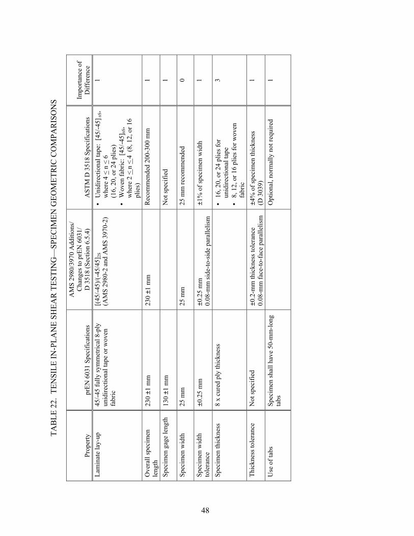
TAB
LE 2
2. T
ENSI
LE IN
-PLA
NE
SHEA
R T
ESTI
NG
—SP
ECIM
EN G
EOM
ETR
IC C
OM
PAR
ISO
NS
AM
S 29
80/3
970
Add
ition
s/
Cha
nges
to p
rEN
603
1/
D 3
518
(Sec
tion
6.5.
4)
Prop
erty
pr
EN 6
031
Spec
ifica
tions
A
STM
D 3
518
Spec
ifica
tions
Im
porta
nce
of
Diff
eren
ce
Lam
inat
e la
y-up
45
/-45
fully
sym
met
rical
8-p
ly
unid
irect
iona
l tap
e or
wov
en
fabr
ic
[(45
/-45)
/(-45
/45]
(A
MS
2980
-2 a
nd A
MS
3970
-2)
• U
nidi
rect
iona
l tap
e: [
45/-4
5],
whe
re 4
n
S<
n 6
(1
6, 2
0, o
r 24
plie
s)
2S
<
Wov
en fa
bric
: [4
5/-4
5]nS
, w
here
2 <
n <
4 (
8, 1
2, o
r 16
plie
s)
1
Ove
rall
spec
imen
le
ngth
23
0 ±1
mm
23
0 ±1
mm
R
ecom
men
ded
200-
300
mm
1
Spec
imen
gag
e le
ngth
13
0 ±1
mm
N
otsp
ecifi
ed1
Spec
imen
wid
th
25 m
m
25 m
m
25 m
m re
com
men
ded
0
Spec
imen
wid
th
tole
ranc
e ±0
.25
mm
±0.2
5 m
m
0.08
-mm
side
-to-s
ide
para
llelis
m
±1%
of s
peci
men
wid
th
1
8 x
cure
d pl
y th
ickn
ess
16
, 20,
or 2
4 pl
ies f
or
unid
irect
iona
l tap
e 8,
12,
or 1
6 pl
ies f
or w
oven
fa
bric
3
Thic
knes
s tol
eran
ce
Not
spec
ified
±0
.2-m
m th
ickn
ess t
oler
ance
0.
08-m
m fa
ce-to
-fac
e pa
ralle
lism
±4
% o
f spe
cim
en th
ickn
ess
(D 3
039)
1
Use
of t
abs
Spec
imen
shal
l hav
e 50
-mm
-long
ta
bs
O
ptio
nal,
norm
ally
not
requ
ired
1
•
Spec
imen
thic
knes
s • •
48

TAB
LE 2
3. T
ENSI
LE IN
-PLA
NE
SHEA
R T
ESTI
NG
—TE
ST P
RO
CED
UR
E C
OM
PAR
ISO
NS
Proc
edur
e pr
EN 6
031
Spec
ifica
tions
AM
S 29
80/3
970
Add
ition
s/
Cha
nges
to p
rEN
603
1/
D 3
518
(Sec
tion
6.5.
4)
AST
M D
351
8 Sp
ecifi
catio
ns
Impo
rtanc
e of
D
iffer
ence
Lo
ad in
dica
tor
Acc
urat
e to
with
in 1
% o
f the
lo
ad ra
nge
used
Acc
urac
y ov
er th
e lo
ad ra
nge(
s) o
f in
tere
st o
f with
in ±
1% o
f the
indi
cate
d va
lue
0
Grip
s W
edge
act
ion
or h
ydra
ulic
Hig
hly
desi
rabl
e to
use
rota
tiona
lly
self-
alig
ning
grip
s to
redu
ce b
endi
ng
stre
ss
1
Spec
imen
alig
nmen
t A
s acc
urat
e as
pos
sibl
e
Rec
omm
ends
lim
iting
per
cent
ben
ding
to
a ra
nge
of 3
% to
5%
stra
in le
vels
>
1000
µε
1
Test
spee
d 1
mm
/min
unt
il 2%
stra
in,
10 m
m/m
in th
erea
fter
2 m
m/m
in
Con
stan
t hea
d-sp
eed
test
s: 2
mm
/min
St
rain
con
trolle
d te
sts:
0.0
1 m
in-1
1
Sam
plin
g Fi
ve sp
ecim
ens
Six
spec
imen
s (A
MS
2980
-2 a
nd
AM
S 39
70-2
) A
t lea
st fi
ve sp
ecim
ens
2
Stra
in g
age
sele
ctio
n 5-
to 1
0-m
m a
ctiv
e ga
ge le
ngth
• • •
Req
uire
d ac
tive
gage
leng
th o
f at
leas
t 3 m
m (6
mm
reco
mm
ende
d fo
r m
ost m
ater
ials
) R
ecom
men
ded
activ
e ga
ge le
ngth
≥
the
char
acte
ristic
-rep
eatin
g un
it of
th
e w
eave
for w
oven
fabr
ic
lam
inat
es
Rec
omm
ende
d re
sist
ance
≥ 3
50 Ω
1
Exte
nsom
eter
s • •
• •
Bid
irect
iona
l ext
enso
met
er
can
be u
sed
Acc
urat
e to
with
in 1
%
R
ecom
men
ded
gage
leng
th in
the
rang
e of
10
to 5
0 m
m
Exte
nsom
eter
shal
l sat
isfy
Pra
ctic
e E
83
1
49
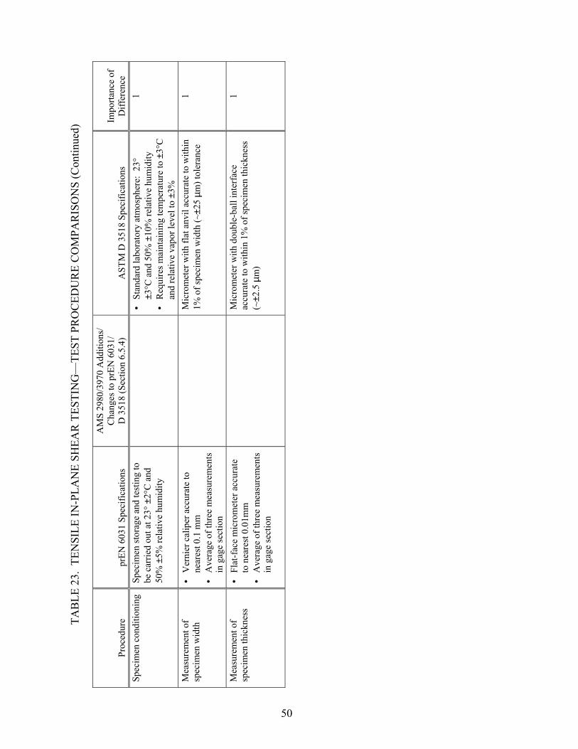
TAB
LE 2
3. T
ENSI
LE IN
-PLA
NE
SHEA
R T
ESTI
NG
—TE
ST P
RO
CED
UR
E C
OM
PAR
ISO
NS
(Con
tinue
d)
Proc
edur
e pr
EN 6
031
Spec
ifica
tions
AM
S 29
80/3
970
Add
ition
s/
Cha
nges
to p
rEN
603
1/
D 3
518
(Sec
tion
6.5.
4)
AST
M D
351
8 Sp
ecifi
catio
ns
Impo
rtanc
e of
D
iffer
ence
Sp
ecim
en c
ondi
tioni
ng
Spec
imen
stor
age
and
test
ing
to
be c
arrie
d ou
t at 2
3° ±
2°C
and
50
% ±
5% re
lativ
e hu
mid
ity
• •
Stan
dard
labo
rato
ry a
tmos
pher
e: 2
3°
±3°C
and
50%
±10
% re
lativ
e hu
mid
ity
Req
uire
s mai
ntai
ning
tem
pera
ture
to ±
3°C
an
d re
lativ
e va
por l
evel
to ±
3%
1
Mea
sure
men
t of
spec
imen
wid
th
• •
Ver
nier
cal
iper
acc
urat
e to
ne
ares
t 0.1
mm
A
vera
ge o
f thr
ee m
easu
rem
ents
in
gag
e se
ctio
n
M
icro
met
er w
ith fl
at a
nvil
accu
rate
to w
ithin
1%
of s
peci
men
wid
th (~
±25
µm) t
oler
ance
1
Mea
sure
men
t of
spec
imen
thic
knes
s • •
Flat
-fac
e m
icro
met
er a
ccur
ate
to n
eare
st 0
.01m
m
Ave
rage
of t
hree
mea
sure
men
ts
in g
age
sect
ion
M
icro
met
er w
ith d
oubl
e-ba
ll in
terf
ace
accu
rate
to w
ithin
1%
of s
peci
men
thic
knes
s (~
±2.5
µm
)
1
50

TAB
LE 2
4. T
ENSI
LE IN
-PLA
NE
SHEA
R T
ESTI
NG
—D
ATA
RED
UC
TIO
N/R
EPO
RTI
NG
CO
MPA
RIS
ON
S
Qua
ntity
pr
EN 6
031
Spec
ifica
tions
AM
S 29
80/3
970
Add
ition
s/
Cha
nges
to p
rEN
603
1/D
351
8 (S
ectio
n 6.
5.4)
A
STM
D 3
518
Spec
ifica
tions
Im
porta
nce
of
Diff
eren
ce
Spec
imen
are
a, A
A
vera
ge o
f thr
ee w
idth
m
easu
rem
ents
tim
es a
vera
ge o
f th
ree
thic
knes
s mea
sure
men
ts
(with
in g
age
sect
ion)
A
vera
ge o
f thr
ee a
rea
mea
sure
men
ts
with
in g
age
sect
ion
(A =
w ×
h)
1
Max
imum
shea
r stre
ss
• •
• •
• • • •
Use
max
imum
tens
ile lo
ad
durin
g te
stin
g U
se a
vera
ge o
f thr
ee w
idth
and
th
ree
thic
knes
s mea
sure
men
ts
for a
rea
Det
erm
ine
shea
r stre
ss a
t: 0.
2% o
ffse
t she
ar st
rain
, 5%
shea
r stra
in, a
nd u
ltim
ate
Cal
cula
ted
and
repo
rted
usin
g bo
th th
e av
erag
e m
easu
red
lam
inat
e th
ickn
ess a
nd th
e no
min
al la
min
ate
thic
knes
s
Use
max
imum
load
at o
r bel
ow 5
%
shea
r stra
in
Cal
cula
ted
usin
g th
e av
erag
e sp
ecim
en a
rea
Rep
ort t
o th
ree
sign
ifica
nt fi
gure
s C
alcu
latio
n of
0.2
% o
ffse
t she
ar
stre
ngth
is o
ptio
nal
1
Max
imum
shea
r stra
in
Not
add
ress
ed
Not
add
ress
ed
• •
Use
min
imum
of 5
% o
r γ12
at
max
imum
shea
r stre
ss
Rep
ort t
o th
ree
sign
ifica
nt fi
gure
s
NC
Shea
r mod
ulus
M
odul
us re
fere
nce
poin
ts: 5
00-
2500
µε
• •
• • •
Mod
ulus
refe
renc
e po
ints
: 20
00-6
000
µε
Cal
cula
ted
and
repo
rted
usin
g bo
th th
e av
erag
e m
easu
red
lam
inat
e th
ickn
ess a
nd th
e no
min
al la
min
ate
thic
knes
s
Cho
rd m
odul
us o
ver a
400
0 ±2
00 µε
shea
r stra
in ra
nge,
star
ting
with
the
low
er st
rain
poi
nt in
the
rang
e of
150
0 to
250
0 µε
R
epor
t to
thre
e si
gnifi
cant
figu
res
Rep
ort s
hear
stra
in ra
nge
used
1
Failu
re m
ode
Not
add
ress
ed
• •
No
tens
ion
or sh
ear f
ailu
re
befo
re d
efin
ed st
rain
leve
ls
Ulti
mat
e fa
ilure
with
in th
e ga
ge le
ngth
Not
add
ress
ed
NC
Stat
istic
s In
divi
dual
val
ues,
mea
n va
lue,
and
st
anda
rd d
evia
tion
of te
nsile
st
reng
th
In
divi
dual
val
ues,
aver
age
valu
e,
stan
dard
dev
iatio
n, a
nd c
oeff
icie
nt o
f va
riatio
n
1
51
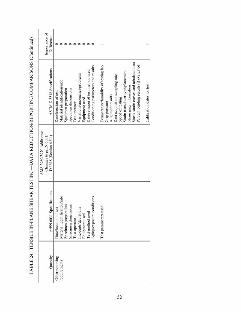
TAB
LE 2
4. T
ENSI
LE IN
-PLA
NE
SHEA
R T
ESTI
NG
—D
ATA
RED
UC
TIO
N/R
EPO
RTI
NG
CO
MPA
RIS
ON
S (C
ontin
ued)
Qua
ntity
pr
EN 6
031
Spec
ifica
tions
AM
S 29
80/3
970
Add
ition
s/
Cha
nges
to p
rEN
603
1/
D 3
518
(Sec
tion
6.5.
4)
AST
M D
351
8 Sp
ecifi
catio
ns
Impo
rtanc
e of
D
iffer
ence
O
ther
repo
rting
re
quire
men
ts
Dat
e/lo
catio
n of
test
M
ater
ial i
dent
ifica
tion/
info
Sp
ecim
en p
repa
ratio
n Sp
ecim
en d
imen
sion
s Te
st o
pera
tor
Inci
dent
s/de
viat
ions
Eq
uipm
ent u
sed
Test
met
hod
used
A
ging
/exp
osur
e co
nditi
ons
Test
par
amet
ers u
sed
D
ate/
loca
tion
of te
st
Mat
eria
l ide
ntifi
catio
n/in
fo
Spec
imen
pre
para
tion
Spec
imen
dim
ensi
ons
Test
ope
rato
r V
aria
tions
/ano
mal
ies/
prob
lem
s Eq
uipm
ent u
sed
Dat
e/re
visi
on o
f tes
t met
hod
used
C
ondi
tioni
ng p
aram
eter
s and
resu
lts
Tem
pera
ture
/hum
idity
of t
estin
g la
b
Grip
pre
ssur
e A
lignm
ent r
esul
ts
Dat
a ac
quis
ition
sam
plin
g ra
te
Spee
d of
test
ing
Stra
in tr
ansd
ucer
type
/pla
cem
ent
Stra
in g
age
info
rmat
ion
Stre
ss-s
train
cur
ves a
nd ta
bula
ted
data
Pe
rcen
t ben
ding
resu
lts (i
f eva
luat
ed)
Cal
ibra
tion
date
s for
test
0 0 0 0 0 0 0 0 0 1 1
52

2.9 BEARING STRENGTH TESTING.
The two test methods considered, prEN 6037 and ASTM D 5961 procedure A, are similar test methods for determining the bearing strength of multidirectional composite laminates using a double-shear, tensile-loading procedure (tables 25 through 27). The AMS 2980 and 3970 specifications provide additions and changes only to prEN 6037; the ASTM D 5961 standard is not referred to in either AMS specification. Note, however, that the only additions or changes specified in AMS 2980 and 3970 are the laminate lay-up and that six specimens be tested. prEN 6037 also requires six specimens, whereas ASTM D 5961 requires that at least five specimens be tested. A comparison of specimen geometries revealed several minor differences in specimen length, edge distance, specimen width, hole diameter, and resulting ratio of specimen width to hole diameter. Since localized bearing failure is produced in this test, none of these differences are expected to produce significant effects on results. However, tolerance differences for the hole diameter and pin diameter produce differences in hole clearance. For prEN 6037, the resulting hole clearance (difference between the hole and pin diameter) will range between 0.0127 and 0.127 mm, whereas for ASTM D 5961, the hole clearance will range between 0.00 and 0.06 mm. This difference in range may produce minimal differences in the measured bearing strength. The loading procedure also differs between the two test methods, with prEN 6037 including an unload/reload step following the estimated yield load that is not present in ASTM D 5961. Perhaps the most significant difference between the two test methods is the specification of fastener torque. Note that prEN 6037 specifies no torque and a minimum clearance on either side of the specimen. In contrast, ASTM D 5961 specifies a standard fastener torque of 2.2-3.4 N-m but allows for any variation if documented. Using this standard value of fastener torque could produce moderate to major differences in the results compared to the specified clearance in prEN 6037. This difference in bearing strength results from the difference in restraint against out-of-plane hole deformation that is provided by the fixture or the fastener. Note, however, that this difference could be reduced or eliminated if the torque was reduced or eliminated, as permitted in ASTM D 5961.
53

TAB
LE 2
5. B
EAR
ING
TES
TIN
G—
SPEC
IMEN
GEO
MET
RIC
CO
MPA
RIS
ON
S
Prop
erty
pr
EN 6
037
Spec
ifica
tions
AM
S 29
80/3
970
Add
ition
s/
Cha
nges
to p
rEN
603
7 (S
ectio
n 6.
5.10
) A
STM
D 5
961
Spec
ifica
tions
(D
oubl
e sh
ear,
proc
edur
e A
) Im
porta
nce
of
Diff
eren
ce
Lam
inat
e la
y-up
• •
• • Ta
pe:
mul
tidire
ctio
nal
dire
cted
or q
uasi
-isot
ropi
c la
min
ates
Fa
bric
: qu
asi-i
sotro
pic
lam
inat
e
[(0/
90)/(
45/-4
5)] 3S
(A
MS
2980
-2)
[(45
/-45)
/(0/9
0)/(-
45/4
5)/(9
0/0)
] 2S
(AM
S 39
70-2
)
Mul
tidire
ctio
nal f
iber
orie
ntat
ions
B
alan
ced
and
sym
met
ric st
acki
ng
sequ
ence
s
1
Ove
rall
spec
imen
le
ngth
15
0 m
m ±
1
13
5m
m1
Req
uire
d sp
ecim
en
wid
th
35 m
m ±
0.1
36m
m1
Req
uire
d sp
ecim
en
wid
th to
lera
nce
±0.1
mm
±1 m
m
1
Spec
imen
thic
knes
s A
ccor
ding
to la
min
ate
lay-
up
4-m
m n
omin
al th
ickn
ess
4-
mm
nom
inal
thic
knes
s Pe
rmis
sibl
e ra
nge
of 3
-5 m
m
0
Hol
e di
amet
er
6.35
mm
6m
m1
Hol
e to
lera
nce
+0.0
889/
-0.0
0 m
m
+0
.03/
-0.0
0 m
m
2
Fast
ener
(pin
) D
iam
eter
6.
35 m
m
6
mm
1
Fast
ener
(pin
) to
lera
nce
-0.0
127/
-0.0
381
mm
±0.0
0/-0
.03
mm
2
Edge
dis
tanc
e 20
mm
18 ±
1mm
1
54

TAB
LE 2
5. B
EAR
ING
TES
TIN
G—
SPEC
IMEN
GEO
MET
RIC
CO
MPA
RIS
ON
S (C
ontin
ued)
Prop
erty
pr
EN 6
037
Spec
ifica
tions
AM
S 29
80/3
970
Add
ition
s/
Cha
nges
to p
rEN
603
7 (S
ectio
n 6.
5.10
) A
STM
D 5
961
Spec
ifica
tions
(D
oubl
e sh
ear,
proc
edur
e A
) Im
porta
nce
of
Diff
eren
ce
Rat
io o
f spe
cim
en
wid
th to
hol
e di
amet
er
5.5
6
1
Rat
io o
f hol
e di
amet
er to
thic
knes
s of
spec
imen
Not
add
ress
ed
1.
5-3.
0 pr
efer
red
NC
Tabs
• •
Spec
imen
type
1:
optio
nal -
50 m
m le
ngth
Sp
ecim
en ty
pe 2
: w
ithou
t ta
bs
Ta
bs n
ot re
quire
d
1
55

TAB
LE 2
6. B
EAR
ING
TES
TIN
G—
TEST
PR
OC
EDU
RE
CO
MPA
RIS
ON
S
Proc
edur
e pr
EN 6
037
Spec
ifica
tions
AM
S 29
80/3
970
Add
ition
s/
Cha
nges
to p
rEN
603
7 (S
ectio
n 6.
5.10
) A
STM
D 5
961
Spec
ifica
tions
(D
oubl
e sh
ear,
proc
edur
e A
) Im
porta
nce
of
Diff
eren
ce
Test
pro
cedu
res
prov
ided
G
ives
two
proc
edur
es fo
r dou
ble
shea
r: •
Spec
imen
type
1:
grip
ped
with
op
tiona
l tab
s •
Spec
imen
type
2:
pin-
load
ed w
ith
1/2″
hol
e
Lo
ad a
pplie
d to
spec
imen
by
mea
ns o
f a
doub
le-s
hear
cle
vis u
sing
the
load
ed fa
sten
er
or p
in (p
roce
dure
A).
1
Load
indi
cato
r • •
Acc
urat
e to
with
in 1
%
Sele
ct lo
ad ra
nge
such
that
failu
re
will
occ
ur b
etw
een
20%
and
80%
of
the
full
scal
e
A
ccur
acy
over
the
load
rang
e(s)
of i
nter
est o
f w
ithin
±1%
of t
he in
dica
ted
valu
e 0
Spec
imen
alig
nmen
t En
sure
spec
imen
is p
erfe
ctly
alig
ned
and
cent
ered
on
the
mac
hine
axi
s.
Take
ext
rem
e ca
re w
ith th
is o
pera
tion
sinc
e it
affe
cts t
he re
sults
and
the
scat
ter.
Ta
ke c
are
to a
lign
the
long
axi
s of t
he g
rippe
d fix
ture
with
the
test
dire
ctio
n 0
Test
spee
d 1
mm
/min
Con
stan
t hea
d-sp
eed
test
s: 2
mm
/min
St
rain
con
trolle
d te
sts:
0.0
1 m
in-1
1
Sam
plin
g Si
x sp
ecim
ens
Six
spec
imen
s (A
MS
2980
-2
and
AM
S 39
70-2
) A
t lea
st fi
ve sp
ecim
ens
2
Hol
e pr
epar
atio
n Fo
llow
EN
256
5 m
etho
d B
for c
arbo
n an
d EN
237
4 m
etho
d B
for g
lass
• •
Hol
es sh
ould
be
drill
ed u
nder
size
d an
d re
amed
to fi
nal d
imen
sion
s Sp
ecia
l car
e sh
all b
e ta
ken
to e
nsur
e th
at
crea
tion
of th
e sp
ecim
en h
ole
does
not
de
lam
inat
e or
oth
erw
ise
dam
age
the
surr
ound
ing
mat
eria
l
1
Spec
imen
co
nditi
onin
g
Spec
imen
stor
age
and
test
ing
to b
e ca
rrie
d ou
t at 2
3° ±
2°C
and
50%
±5%
re
lativ
e hu
mid
ity
• •
Stan
dard
labo
rato
ry a
tmos
pher
e: 2
3° ±
3°C
an
d 50
% ±
10%
rela
tive
hum
idity
R
equi
res m
aint
aini
ng te
mpe
ratu
re to
with
in
±3°C
and
rela
tive
vapo
r lev
el to
with
in ±
3%
1
56

TAB
LE 2
6. B
EAR
ING
TES
TIN
G—
TEST
PR
OC
EDU
RE
CO
MPA
RIS
ON
S (C
ontin
ued)
Proc
edur
e pr
EN 6
037
Spec
ifica
tions
AM
S 29
80/3
970
Add
ition
s/
Cha
nges
to p
rEN
603
7 (S
ectio
n 6.
5.10
) A
STM
D 5
961
Spec
ifica
tions
(D
oubl
e sh
ear,
proc
edur
e A
) Im
porta
nce
of
Diff
eren
ce
Mea
sure
men
t of
spec
imen
wid
th
Mic
rom
eter
with
flat
anv
il ac
cura
te to
with
in 0
.01
mm
Mic
rom
eter
with
flat
anv
il ac
cura
te to
with
in
1% o
f spe
cim
en w
idth
(~±2
5 µm
) 1
Mea
sure
men
t of
spec
imen
thic
knes
s • •
• •
Mic
rom
eter
with
flat
anv
il ac
cura
te to
with
in 0
.01
mm
A
vera
ge o
f thr
ee
mea
sure
men
ts se
lect
ed a
s re
pres
enta
tive
of
neig
hbor
hood
of t
he h
ole
M
icro
met
er w
ith d
oubl
e-ba
ll in
terf
ace
accu
rate
to w
ithin
1%
of s
peci
men
th
ickn
ess (
~±2.
5 µm
) on
irreg
ular
surf
aces
M
icro
met
er w
ith fl
at a
nvil
accu
rate
to
with
in 1
% o
f spe
cim
en th
ickn
ess
(~±2
.5 µ
m) o
n ve
ry sm
ooth
-tool
ed
surf
aces
1
Mea
sure
men
t of h
ole
diam
eter
M
icro
met
er w
ith fl
at a
nvil
accu
rate
to w
ithin
0.0
1 m
m
A
ccur
ate
to w
ithin
1%
of h
ole
diam
eter
1
Fast
ener
torq
ue
No
torq
ue a
pplie
d (le
ave
0.1-
mm
cle
aran
ce o
n ea
ch si
de
of sp
ecim
en)
• • •
2.2-
3.4
N-m
(nom
inal
) Th
e no
min
al te
st c
onfig
urat
ion
uses
a
rela
tivel
y lo
w le
vel o
f fas
tene
r ins
talla
tion
torq
ue to
giv
e co
nser
vativ
e be
arin
g st
ress
re
sults
R
esul
ts a
re a
ffec
ted
by th
e in
stal
led
fast
ener
pre
load
3-4
Mea
sure
men
t of
fast
ener
torq
ue
Not
app
licab
le
To
rque
wre
nch
capa
ble
of d
eter
min
ing
the
appl
ied
torq
ue to
with
in ±
0% o
f des
ired
valu
e N
C
Mea
sure
men
t of
bear
ing
stra
in
Exte
nsom
eter
(50-
mm
gag
e le
ngth
reco
mm
ende
d) o
r eq
uiva
lent
stra
in m
easu
ring
devi
ce a
ccur
ate
to w
ithin
1%
in
the
load
rang
e us
ed
B
earin
g st
rain
dat
a sh
all b
e de
term
ined
by
a be
arin
g st
rain
indi
cato
r abl
e to
mea
sure
lo
ngitu
dina
l hol
e de
form
atio
n re
lativ
e to
the
fixtu
re si
mul
tane
ousl
y on
opp
osite
edg
es o
f th
e sp
ecim
en
1
Load
ing
proc
edur
e •
Load
spec
imen
to e
stim
ated
yi
eld
load
, the
n un
load
to a
va
lue
of a
bout
10%
-20%
•
Rel
oade
d un
til fa
ilure
occ
urs
Sp
ecim
en is
load
ed u
ntil
a m
axim
um is
re
ache
d an
d lo
ad h
as d
ropp
ed o
ff a
bout
30%
fr
om m
axim
um
2
57

TAB
LE 2
7. B
EAR
ING
TES
TIN
G—
DA
TA R
EDU
CTI
ON
/REP
OR
TIN
G C
OM
PAR
ISO
NS
Qua
ntity
pr
EN 6
037
Spec
ifica
tions
AM
S 29
80/3
970
Add
ition
s/
Cha
nges
to p
rEN
603
7 (S
ectio
n 6.
5.10
) A
STM
D 5
961
Spec
ifica
tions
(D
oubl
e sh
ear,
proc
edur
e A
) Im
porta
nce
ofD
iffer
ence
U
ltim
ate
bear
ing
stre
ngth
Fa
ilure
load
div
ided
by
bear
ing
area
Failu
re lo
ad d
ivid
ed b
y be
arin
g ar
ea
Rep
ort t
o th
ree
sign
ifica
nt fi
gure
s 0
Bea
ring
stra
in
N
ot a
ddre
ssed
Ave
rage
dis
plac
emen
t fro
m tw
o in
dica
tors
di
vide
d by
the
hole
dia
met
er
NC
Bea
ring
chor
d st
iffne
ss
N
ot a
ddre
ssed
Cho
rd st
iffne
ss in
the
esse
ntia
lly li
near
por
tion
of th
e be
arin
g st
ress
/bea
ring
stra
in c
urve
N
C
Effe
ctiv
e or
igin
N
ot a
ddre
ssed
Inte
rsec
tion
of th
e ch
ord
stiff
ness
line
with
the
bear
ing
stra
in a
xis
NC
Ulti
mat
e be
arin
g st
rain
Not
add
ress
ed
B
earin
g st
rain
at u
ltim
ate
load
usi
ng th
e ef
fect
ive
orig
in fo
r bea
ring
stra
in
NC
Yie
ld b
earin
g st
reng
th
vs o
ffse
t bea
ring
stre
ngth
Yie
ld b
earin
g st
reng
th:
•
Text
: lo
ad a
t 2%
per
man
ent
hole
elo
ngat
ion
divi
ded
by
bear
ing
area
•
Figu
re:
Sugg
ests
usi
ng th
e in
ters
ectio
n of
load
/ el
onga
tion
curv
e an
d 2%
of
fset
stiff
ness
line
(usi
ng
relo
adin
g sl
ope)
O
ffse
t bea
ring
stre
ngth
: U
sing
eff
ectiv
e or
igin
, th
e in
ters
ectio
n of
the
bear
ing
stre
ss/s
train
cu
rve
with
the
bear
ing
chor
d st
iffne
ss li
ne th
at
has a
spec
ified
stra
in o
ffse
t (ex
: 2%
)
NC
Initi
al p
eak
bear
ing
stre
ngth
Not
add
ress
ed
B
earin
g st
ress
at i
nitia
l pea
k w
hen
follo
wed
by
a sh
arp
drop
in b
earin
g st
reng
th
NC
58
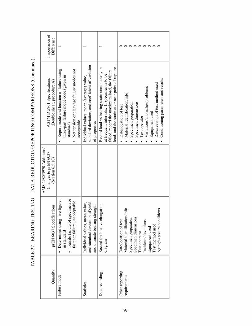
TAB
LE 2
7. B
EAR
ING
TES
TIN
G—
DA
TA R
EDU
CTI
ON
/REP
OR
TIN
G C
OM
PAR
ISO
NS
(Con
tinue
d)
Qua
ntity
pr
EN 6
037
Spec
ifica
tions
AM
S 29
80/3
970
Add
ition
s/
Cha
nges
to p
rEN
603
7 (S
ectio
n 6.
5.10
) A
STM
D 5
961
Spec
ifica
tions
(D
oubl
e sh
ear,
proc
edur
e A
) Im
porta
nce
ofD
iffer
ence
Fa
ilure
mod
e • •
• •
Det
erm
ined
usi
ng fi
ve fi
gure
s in
stan
dard
Te
nsile
failu
re o
f spe
cim
en o
r fa
sten
er fa
ilure
una
ccep
tabl
e
R
epor
t mod
e an
d lo
catio
n of
failu
re u
sing
th
ree-
part
failu
re m
ode
code
(giv
en in
st
anda
rd)
Net
tens
ion
or c
leav
age
failu
re m
odes
not
ac
cept
able
1
Stat
istic
s In
divi
dual
val
ues,
mea
n va
lue,
an
d st
anda
rd d
evia
tion
of y
ield
an
d ul
timat
e be
arin
g st
reng
th
In
divi
dual
val
ues,
mea
n (a
vera
ge) v
alue
, st
anda
rd d
evia
tion,
and
coe
ffic
ient
of v
aria
tion
of p
rope
rties
1
Dat
a re
cord
ing
Rec
ord
the
load
vs e
long
atio
n di
agra
m
R
ecor
d lo
ad v
s bea
ring
stra
in c
ontin
uous
ly o
r at
freq
uent
inte
rval
s. If
spec
imen
is to
be
faile
d, re
cord
the
max
imum
load
, the
failu
re
load
, and
the
stra
in a
t or n
ear p
oint
of r
uptu
re.
1
Oth
er re
porti
ng
requ
irem
ents
D
ate/
loca
tion
of te
st
Mat
eria
l ide
ntifi
catio
n/in
fo
Spec
imen
pre
para
tion
Spec
imen
dim
ensi
ons
Test
ope
rato
r In
cide
nts/
devi
atio
ns
Equi
pmen
t use
d Te
st m
etho
d us
ed
Agi
ng/e
xpos
ure
cond
ition
s
• • • • • • • • •
Dat
e/lo
catio
n of
test
M
ater
ial i
dent
ifica
tion/
info
Sp
ecim
en p
repa
ratio
n Sp
ecim
en d
imen
sion
s Te
st o
pera
tor
Var
iatio
ns/a
nom
alie
s/pr
oble
ms
Equi
pmen
t use
d D
ate/
revi
sion
of t
est m
etho
d us
ed
Con
ditio
ning
par
amet
ers a
nd re
sults
0 0 0 0 0 0 0 0 0
59

TAB
LE 2
7. B
EAR
ING
TES
TIN
G—
DA
TA R
EDU
CTI
ON
/REP
OR
TIN
G C
OM
PAR
ISO
NS
(Con
tinue
d)
Qua
ntity
pr
EN 6
037
Spec
ifica
tions
AM
S 29
80/3
970
Add
ition
s/
Cha
nges
to p
rEN
603
7 (S
ectio
n 6.
5.10
) A
STM
D 5
961
Spec
ifica
tions
(D
oubl
e sh
ear,
proc
edur
e A
) Im
porta
nce
ofD
iffer
ence
O
ther
repo
rting
re
quire
men
ts
(con
tinue
d)
Test
par
amet
ers u
sed
• • • • • • • • • • • • • •
Wid
th to
dia
met
er ra
tio fo
r eac
h sp
ecim
en
Edge
dis
tanc
e ra
tio fo
r eac
h sp
ecim
en
Dia
met
er to
thic
knes
s rat
io fo
r eac
h sp
ecim
en a
nd n
omin
al v
alue
A
vera
ge p
ly th
ickn
ess o
f the
mat
eria
l Fa
sten
er o
r pin
type
Fa
sten
er o
r pin
dia
met
er
Fast
ener
torq
ue (i
f app
ropr
iate
) H
ole
clea
ranc
e B
earin
g st
rain
indi
cato
r pla
cem
ent o
n sp
ecim
en
Tem
pera
ture
/hum
idity
of t
estin
g la
b
Grip
pre
ssur
e D
ata
acqu
isiti
on sa
mpl
ing
rate
Sp
eed
of te
stin
g
Cal
ibra
tion
date
s for
test
1 1
60

2.10 COMPRESSION AFTER IMPACT TESTING.
Although both of the compression after impact test methods compared involve drop-weight impact testing followed by edgewise compression testing, these two test methods serve very different purposes (tables 28 through 30). Test method prEN 6038 focuses on the energy level associated with barely visible impact damage (BVID), a damage state defined as producing a 0.3-mm-deep indentation in the impacted surface. In contrast, SACMA SRM 2R is intended as either a screening or comparison test and uses a single impact energy level. Note that the two AMS specifications, AMS 2980 and 3970, provide additions and changes only to prEN 6038; the SACMA SRM 2R standard is not referred to in either AMS specification. Thus, the AMS specifications serve the same general purpose of prEN 6038 and focus on examining the BVID and the compression after impact strength associated with this damage state. Although there are many significant differences in the test procedures between the two compression after impact test methods considered, the specimen, impact support fixture, and compression after impact test fixture specifications are very similar. The most significant difference is the recommended mass of the impactor. Significant differences between the two test methods include the number and magnitude of specified impact energy levels, the method of postimpact nondestructive inspection, and the number of specimens impacted and compression-tested. The most significant of the modifications listed in the AMS specifications involve the number of impact energy levels used. Whereas prEN 6038 requires impacting at a total of seven different energy levels, the AMS specifications start the impacting with the lowest energy level and increase the impact energy until an indentation depth of 0.3 mm is created. Once this indentation depth has been obtained, only one additional impact energy level is required.
61

TAB
LE 2
8. C
OM
PRES
SIO
N A
FTER
IMPA
CT
TEST
ING
—SP
ECIM
EN/F
IXTU
RE
GEO
MET
RIC
CO
MPA
RIS
ON
S
Prop
erty
pr
EN 6
038
Spec
ifica
tions
AM
S 29
80/3
970
Add
ition
s/
Cha
nges
to p
rEN
603
8 (S
ectio
n 6.
5.11
) SA
CM
A S
RM
2R
199
4 Sp
ecifi
catio
ns
Impo
rtanc
e of
D
iffer
ence
La
min
ate
lay-
up
Qua
si-is
otro
pic
spec
imen
•
Tape
: [(
45/0
/-45/
90]n
S w
ith n
ch
osen
to o
btai
n th
ickn
ess ~
4 m
m
• •
Fabr
ic:
[(45
/-45)
/(90/
0)]m
S w
ith n
ch
osen
to o
btai
n th
ickn
ess ~
4 m
m
[(45
/-45)
/(90/
0)] 6S
(A
MS
2980
-2)
[(45
/-45)
/(0/9
0)/(-
45/4
5)/(9
0/0)
] 3S
(AM
S 39
70-2
)
Qua
si-is
otro
pic
spec
imen
•
Tape
: 24-
48 p
lies o
f tap
e
[(45
/0/-4
5/90
]nS
Fabr
ic: s
uffic
ient
plie
s to
achi
eve
4.5-
5.6
mm
thic
knes
s
1
Spec
imen
leng
th
150
mm
150
mm
0
Spec
imen
leng
th
tole
ranc
e ±0
.1 m
m
±0
.25
mm
1
Spec
imen
wid
th
100
mm
100
mm
0
Spec
imen
wid
th
tole
ranc
e ±0
.1 m
m
±0
.25
mm
1
Para
llelis
m a
nd
perp
endi
cula
rity
• •
Spec
imen
side
s: 0
.02-
mm
pa
ralle
lism
and
per
pend
icul
ar
requ
irem
ent
Spec
imen
end
s: 0
.012
5-m
m
para
llelis
m re
quire
men
t
En
ds sh
all b
e m
achi
ned
perp
endi
cula
r to
the
long
itudi
nal s
urfa
ces t
o w
ithin
0.
03 m
m
1
Impa
ct m
achi
ne
• • • •
Dro
p-w
eigh
t im
pact
test
er
Cap
able
of c
aptu
ring
the
drop
w
eigh
t afte
r the
firs
t im
pact
D
rop-
wei
ght i
mpa
ct te
ster
(d
imen
sion
ed fi
gure
pro
vide
d)
Cap
able
of a
void
ing
any
rebo
und
hits
of t
he sp
ecim
en
0 0 M
etho
d of
supp
ortin
g sp
ecim
en d
urin
g im
pact
Secu
re to
20-
mm
-thic
k st
eel b
ase
plat
e us
ing
four
rubb
er-ti
pped
cla
mps
Secu
re to
19-
mm
-thic
k al
umin
um
supp
ort b
ase
usin
g fo
ur ru
bber
-tipp
ed
clam
ps
1
Uns
uppo
rted
area
du
ring
impa
ct
75 ±
0.1
mm
by
125
±0.2
mm
76.2
mm
by
127
mm
1
62

TAB
LE 2
8. C
OM
PRES
SIO
N A
FTER
IMPA
CT
TEST
ING
—SP
ECIM
EN/F
IXTU
RE
GEO
MET
RIC
CO
MPA
RIS
ON
S (C
ontin
ued)
Prop
erty
pr
EN 6
038
Spec
ifica
tions
AM
S 29
80/3
970
Add
ition
s/
Cha
nges
to p
rEN
603
8 (S
ectio
n 6.
5.11
) SA
CM
A S
RM
2R
199
4 Sp
ecifi
catio
ns
Impo
rtanc
e of
D
iffer
ence
Im
pact
or
• • •
• •
Mas
s: 1
-3 k
g or
4-6
kg
to w
ithin
±1
0g
Sphe
re ra
dius
: 8
±0.2
5 m
m
M
ater
ial:
stee
l with
Rm=
2000
MPa
M
ass:
5.6
kg
reco
mm
ende
d
Hem
isph
eric
al ra
dius
:
Sec
tion
6.3:
7
.875
mm
Sec
tion
9.1.
1: 7
.95
mm
•
Mat
eria
l: st
eel,
hard
ened
tip
2 1 1
Com
pres
sion
afte
r im
pact
test
fixt
ure
• •
• •
Sim
ply
supp
orts
test
spec
imen
al
ong
all f
our e
dges
D
raw
ings
of f
ixtu
re g
iven
with
out
dim
ensi
ons o
r ref
eren
ces
. Si
mpl
y su
ppor
ts te
st sp
ecim
en a
long
al
l fou
r edg
es
Dra
win
gs o
f fix
ture
giv
en w
ith
dim
ensi
ons
0 2
63

TAB
LE 2
9. C
OM
PRES
SIO
N A
FTER
IMPA
CT
TEST
ING
—TE
ST P
RO
CED
UR
E C
OM
PAR
ISO
NS
Proc
edur
e pr
EN 6
038
Spec
ifica
tions
AM
S 29
80/3
970
Add
ition
s/
Cha
nges
to p
rEN
603
8 (S
ectio
n 6.
5.11
) SA
CM
A S
RM
2R
199
4 Sp
ecifi
catio
ns
Impo
rtanc
e of
D
iffer
ence
Lo
ad in
dica
tor
• •
Acc
urat
e to
with
in 1
% in
the
rele
vant
load
rang
e Se
lect
load
rang
e so
that
fa
ilure
occ
urs b
etw
een
20%
an
d 80
% o
f the
scal
e
A
s def
ined
by
AST
M E
4
1
Spec
imen
con
ditio
ning
Sp
ecim
en st
orag
e an
d te
stin
g to
be
car
ried
out a
t 23°
±2°
C a
nd
50%
±5%
rela
tive
hum
idity
U
sing
SA
CM
A-r
ecom
men
ded
met
hod
SRM
11
1
Sam
plin
g • •
• •
One
spec
imen
at e
ach
of
seve
n de
fined
ene
rgy
leve
ls
Thre
e sp
ecim
ens a
t BV
ID
leve
l for
com
pres
sion
test
ing
One
or m
ore
spec
imen
s to
dete
rmin
e en
ergy
leve
ls
Thre
e sp
ecim
ens p
er e
nerg
y le
vel f
or c
ompr
essi
on te
stin
g (A
MS
2980
-2 a
nd A
MS
3970
-2)
Min
imum
of f
ive
spec
imen
s at o
ne e
nerg
y le
vel
4
Mea
sure
men
t of
spec
imen
wid
th
• •
• •
Ver
nier
slid
e ca
liper
s ca
libra
ted
to 0
.01-
mm
ac
cura
cy
Thre
e m
easu
rem
ents
at
diff
eren
t poi
nts o
f the
sp
ecim
en
M
icro
met
er w
ith fl
at-f
ace
suita
ble
for
read
ing
to 0
.03-
mm
acc
urac
y
Ave
rage
of n
o le
ss th
an tw
o m
easu
rem
ents
take
n ne
ar th
e sp
ecim
en
cent
er
1
Mea
sure
men
t of
spec
imen
thic
knes
s • •
• •
Flat
-fac
e m
icro
met
er
calib
rate
d to
0.0
1-m
m
accu
racy
Th
ree
mea
sure
men
ts a
t di
ffer
ent p
oint
s of t
he
spec
imen
7-
mm
bal
l-nos
e m
icro
met
er su
itabl
e fo
r re
adin
g to
0.0
3-m
m a
ccur
acy
Ave
rage
of f
our m
easu
rem
ents
take
n ar
ound
the
impa
ct a
rea
prio
r to
impa
ct
1
64

TAB
LE 2
9. C
OM
PRES
SIO
N A
FTER
IMPA
CT
TEST
ING
—TE
ST P
RO
CED
UR
E C
OM
PAR
ISO
NS
(Con
tinue
d)
Proc
edur
e pr
EN 6
038
Spec
ifica
tions
AM
S 29
80/3
970
Add
ition
s/
Cha
nges
to p
rEN
603
8 (S
ectio
n 6.
5.11
) SA
CM
A S
RM
2R
199
4 Sp
ecifi
catio
ns
Impo
rtanc
e of
D
iffer
ence
Im
pact
ene
rgy
leve
ls
• •
9, 1
2, 1
6, 2
0, 2
5, 3
0, a
nd 4
0 Jo
ules
B
VID
leve
l: e
nerg
y co
rres
pond
ing
to a
n in
dent
atio
n de
pth
of 0
.3 m
m
Thre
e im
pact
ene
rgy
leve
ls:
1. E
nerg
y le
vel p
rodu
cing
0.
3-m
m in
dent
atio
n 2.
One
ene
rgy
leve
l bel
ow th
e 0.
3-m
m im
pact
ene
rgy
leve
l 3.
Tw
o en
ergy
leve
ls a
bove
the
0.3-
mm
impa
ct e
nerg
y le
vel
One
impa
ct e
nerg
y le
vel:
6.7
Joul
es p
er m
m o
f pan
el th
ickn
ess
4
Impa
ct e
nerg
y le
vel
tole
ranc
e N
ot sp
ecifi
ed
±10%
N
ot sp
ecifi
ed
NC
Post
impa
ct
nond
estru
ctiv
e in
spec
tion
Insp
ect a
nd a
sses
s the
vis
ibili
ty
of th
e in
dent
atio
n an
d an
y fib
er
brea
ks o
n bo
th fa
ces o
f the
sp
ecim
en
On
at le
ast o
ne re
pres
enta
tive
spec
imen
of e
ach
impa
ct le
vel
dete
rmin
ed fo
r com
pres
sion
te
stin
g
An
ultra
soni
c sc
an o
f the
impa
cted
sp
ecim
en a
nd th
e ge
nera
l con
figur
atio
n of
th
e de
lam
inat
ions
shal
l be
reco
rded
4
Mea
sure
men
t of
impa
ct d
epth
• •
Dep
th g
age
with
3-m
m-
diam
eter
hem
isph
eric
al
adap
ter c
alib
rate
d to
0.0
1-m
m
accu
racy
M
easu
re th
e de
pth
in th
e de
epes
t par
t of t
he in
dent
ed
area
. N
ext,
mea
sure
the
dept
h at
four
poi
nts 2
0 m
m fr
om th
e ce
nter
of i
nden
tatio
n, a
nd
subt
ract
from
the
dept
h at
the
deep
est p
art.
The
inde
nted
de
pth
is th
e av
erag
e of
thes
e fo
ur v
alue
s.
N
ot a
ddre
ssed
N
C
65

TAB
LE 2
9. C
OM
PRES
SIO
N A
FTER
IMPA
CT
TEST
ING
—TE
ST P
RO
CED
UR
E C
OM
PAR
ISO
NS
(Con
tinue
d)
Proc
edur
e pr
EN 6
038
Spec
ifica
tions
AM
S 29
80/3
970
Add
ition
s/
Cha
nges
to p
rEN
603
8 (S
ectio
n 6.
5.11
) SA
CM
A S
RM
2R
199
4 Sp
ecifi
catio
ns
Impo
rtanc
e of
D
iffer
ence
St
rain
gag
e pl
acem
ent
and
usag
e
• •
• • •
25 ±
1 m
m in
war
d fr
om u
pper
co
rner
s and
from
top
and
botto
m o
f the
spec
imen
If re
quire
d in
rele
vant
sp
ecifi
catio
n, tw
o st
rain
gag
es
shou
ld b
e on
the
fron
t fac
e of
th
e lo
wes
t im
pact
ene
rgy
spec
imen
Gag
es to
be
plac
ed o
n bo
th fa
ces
of th
e sp
ecim
en (f
our g
ages
to
tal)
and
coup
led
to th
e re
cord
er su
ch th
at p
anel
bu
cklin
g ca
n be
det
ecte
d
25.4
mm
dow
nwar
d an
d in
war
d fr
om
uppe
r cor
ners
of t
he sp
ecim
en
G
ages
to b
e pl
aced
on
both
side
s of t
he
spec
imen
(fou
r gag
es to
tal).
Out
put o
f ea
ch g
age
shal
l be
plot
ted
indi
vidu
ally
to
che
ck fo
r buc
klin
g
Stra
in g
ages
can
be
omitt
ed if
di
men
sion
al v
aria
tion
in sp
ecim
en a
re
with
in to
lera
nces
giv
en
0 0 N
C
Spec
imen
alig
nmen
t C
aref
ully
alig
n th
e im
pact
ed
spec
imen
in th
e te
st ri
g
Te
st is
sens
itive
to p
aral
lelis
m o
f spe
cim
en
ends
as w
ell a
s per
pend
icul
arity
and
sy
stem
alig
nmen
t
0
Test
spee
d 0.
5 m
m/m
in
1 m
m/m
in
1 m
m/m
in
0
66

TAB
LE 3
0. C
OM
PRES
SIO
N A
FTER
IMPA
CT
TEST
ING
—D
ATA
RED
UC
TIO
N/R
EPO
RTI
NG
CO
MPA
RIS
ON
S
Qua
ntity
pr
EN 6
038
Spec
ifica
tions
AM
S 29
80/3
970
Add
ition
s/
Cha
nges
to p
rEN
603
8 (S
ectio
n 6.
5.11
) SA
CM
A S
RM
2R
199
4 Sp
ecifi
catio
ns
Impo
rtanc
e of
D
iffer
ence
Im
pact
ene
rgy,
E
Eith
er E
= m
g h
o
r
E =
½ m
× v
2
Eith
er E
= d
rop
wei
ght t
imes
dro
p he
ight
di
vide
d by
spec
imen
thic
knes
s or
E =
½ m
× v
2 div
ided
by
spec
imen
th
ickn
ess
2
Spec
imen
are
a, A
W
idth
tim
es th
ickn
ess
A
vera
ge w
idth
tim
es a
vera
ge th
ickn
ess
0
Com
pres
sive
stre
ngth
af
ter i
mpa
ct
Bre
ak fa
ilure
load
div
ided
by
spec
imen
are
a
Ulti
mat
e co
mpr
essi
ve lo
ad d
ivid
ed b
y sp
ecim
en a
rea
0
Nom
inal
com
pres
sive
st
reng
th a
fter i
mpa
ct
Bre
ak fa
ilure
load
div
ided
by
spec
imen
wid
th ti
mes
the
nom
inal
thic
knes
s of t
he
spec
imen
s
R
epor
t nor
mal
izat
ion
met
hod
used
, if a
ny,
for c
ompr
essi
ve st
reng
th
1
Com
pres
sion
mod
ulus
N
ot a
ddre
ssed
• • •
Opt
iona
l U
sing
load
dat
a at
100
0 an
d 30
00 µ
ε St
rain
s bas
ed o
n th
e av
erag
e of
all
four
st
rain
gag
es
NC
Ulti
mat
e st
rain
at
failu
re
Not
add
ress
ed
O
ptio
nal
N
C
Spec
ified
failu
re m
ode
Not
add
ress
ed
Com
pres
sion
failu
re in
clud
ing
at le
ast a
por
tion
of th
e im
pact
ed a
rea
Spec
imen
s tha
t fai
l at a
loca
tion
othe
r tha
n th
e ce
ntra
l im
pact
ed z
one
are
not
acce
ptab
le (r
etes
ts sh
all b
e pe
rfor
med
)
0
Stat
istic
s N
ot a
ddre
ssed
Indi
vidu
al v
alue
s, av
erag
e va
lue,
stan
dard
de
viat
ion,
and
coe
ffic
ient
of v
aria
tion
for
prop
ertie
s det
erm
ined
NC
67

TAB
LE 3
0. C
OM
PRES
SIO
N A
FTER
IMPA
CT
TEST
ING
—D
ATA
RED
UC
TIO
N/R
EPO
RTI
NG
CO
MPA
RIS
ON
S (C
ontin
ued)
Qua
ntity
pr
EN 6
038
Spec
ifica
tions
AM
S 29
80/3
970
Add
ition
s/
Cha
nges
to p
rEN
603
8 (S
ectio
n 6.
5.11
) SA
CM
A S
RM
2R
199
4 Sp
ecifi
catio
ns
Impo
rtanc
e of
D
iffer
ence
O
ther
repo
rting
re
quire
men
ts
• • • • • • • • • • • • • •
• •
• • • • • • • • • • • •
Mat
eria
l ide
ntifi
catio
n/in
fo
Spec
imen
pre
para
tion
Spec
imen
dim
ensi
ons
Dev
iatio
ns fr
om te
st m
etho
d Te
st o
pera
tor
Dat
e/lo
catio
n of
test
Vis
ibili
ty a
nd d
epth
of
inde
ntat
ion
Any
bre
aks i
n th
e fib
ers o
n bo
th fa
ces o
f the
spec
imen
Equi
pmen
t use
d Te
st m
etho
d us
ed
C
urve
of c
ompr
essi
on
stre
ngth
ver
sus e
nerg
y C
urve
of i
nden
tatio
n de
pth
vers
us e
nerg
y B
VID
ene
rgy
leve
l and
co
rres
pond
ing
valu
e of
st
reng
th
Te
st p
aram
eter
s use
d
Im
pact
inde
ntat
ion
dept
hs o
f al
l spe
cim
ens
Vis
ual d
amag
e on
bot
h si
des
of th
e sp
ecim
ens
Mat
eria
l ide
ntifi
catio
n/in
fo
Spec
imen
pre
para
tion
Spec
imen
dim
ensi
ons
Dev
iatio
ns fr
om te
st m
etho
d Te
st o
pera
tor
Dat
e/lo
catio
n of
test
Dam
aged
are
a M
etho
d us
ed to
det
erm
ine
the
conf
igur
atio
n of
the
dam
aged
are
a
Impa
ct m
etho
d us
ed
Sp
ecim
en p
rete
st c
ondi
tioni
ng h
isto
ry
Tem
pera
ture
/hum
idity
of t
estin
g la
b Fi
ber v
olum
e fr
actio
n of
eac
h sp
ecim
en
0 0 0 0 0 0 4 0 N
C
N
C
N
C
1 1 1
68

2.11 MODE I FRACTURE TOUGHNESS TESTING.
Of the two AMS specifications considered, only AMS 3970 includes Mode I fracture toughness testing (table 31 through 33). Of the two test methods compared, prEN 6033 and ASTM D 5528, only prEN 6033 is referred to in the AMS 3970 specification. However, the only additions or changes to prEN 6033 specified in AMS 3970 are the laminate lay-up and that six specimens be tested. Interestingly, the number of test specimens is not specified in prEN 6033, whereas at least five specimens are specified in ASTM D 5528. Although both prEN 6033 and ASTM D 5528 use a double-cantilever beam specimen to calculate the Mode I fracture toughness, significant differences exist in the specimen configurations. The most significant differences involve the length of the specimen and the length and thickness of the film insert used to produce a delamination in the specimen. Significant differences also exist in the specimen loading procedure, including both the preloading procedure and the subsequent loading. Further, significant differences exist in the method used to calculate the Mode I fracture toughness, GIC. In prEN 6033, GIC is calculated using the area between the loading and unloading curves (force versus crosshead displacement) over a 100-mm length of crack propagation. ASTM D 5528 recommends the use of a modified beam theory method for calculating GIC values as a function of delamination length. Thus, while a single value of GIC is calculated and reported in prEN 6033, a series of GIC values are calculated and three values reported in ASTM D 5528.
69

TAB
LE 3
1. M
OD
E I F
RA
CTU
RE
TOU
GH
NES
S TE
STIN
G—
SPEC
IMEN
GEO
MET
RIC
CO
MPA
RIS
ON
S
Prop
erty
pr
EN 6
033
Spec
ifica
tions
AM
S 39
70 A
dditi
ons/
C
hang
es to
prE
N 6
033
(Sec
tion
6.5.
19)
AST
M D
552
8 Sp
ecifi
catio
ns
Impo
rtanc
e of
D
iffer
ence
La
min
ate
lay-
up
• •
• •
Uni
dire
ctio
nal l
amin
ate
for t
ape
mat
eria
l 0º
/90º
lam
inat
e fo
r fab
ric
mat
eria
l
[(0/
90)]
6S
(AM
S 39
70-2
) U
nidi
rect
iona
l lam
inat
es w
ith a
n ev
en
num
ber o
f plie
s D
elam
inat
ion
grow
th o
ccur
ring
in th
e 0°
di
rect
ion
1
Ove
rall
spec
imen
le
ngth
25
0 ±5
mm
At l
east
125
mm
2
Spec
imen
wid
th
25.0
mm
20 to
25
mm
nom
inal
ly
1
Spec
imen
wid
th
tole
ranc
e ±0
.2 m
m
Not
spec
ified
NC
Spec
imen
th
ickn
ess
3.0
±0.2
mm
4-
mm
nom
inal
thic
knes
s Pe
rmis
sibl
e ra
nge
of 3
-5 m
m
1
Leng
th o
f film
in
sert
25 ±
1 m
m
• •
App
roxi
mat
ely
63 m
m
Initi
al d
elam
inat
ion
leng
th o
f ap
prox
imat
ely
50 m
m p
lus e
xtra
leng
th to
bo
nd h
inge
s or l
oad
bloc
ks
2-3
Rel
ease
film
inse
rt fo
r del
amin
atio
n D
oubl
e la
yer o
f po
lyte
traflu
oret
hyle
ne fo
il, 0
.02-
0.03
mm
thic
k, a
nd p
lace
d at
the
mid
plan
e of
the
lam
inat
e
• • •
Non
adhe
sive
inse
rt at
the
mid
-pla
ne o
f the
la
min
ate
with
film
thic
knes
s no
grea
ter
than
13
µm
Poly
tetra
fluor
ethy
lene
film
reco
mm
ende
d fo
r epo
xy m
atric
es c
ured
at o
r bel
ow 1
77°C
Po
lyim
ide
film
reco
mm
ende
d fo
r po
lyim
ide,
bis
mal
eim
ide,
or t
herm
opla
stic
m
atric
es p
roce
ssed
abo
ve 1
77°C
3-4
Met
hod
of lo
ad
intro
duct
ion
Ben
t alu
min
um st
rips (
0.5-
0.7
mm
th
ick)
or h
inge
d m
etal
lic ta
bs (1
.0-
1.5
mm
thic
k)
Ei
ther
met
al p
iano
hin
ge ta
bs o
r loa
ding
bl
ocks
1
70

TAB
LE 3
2. M
OD
E I F
RA
CTU
RE
TOU
GH
NES
S TE
STIN
G—
TEST
PR
OC
EDU
RE
CO
MPA
RIS
ON
S
Proc
edur
e pr
EN 6
033
Spec
ifica
tions
AM
S 39
70 A
dditi
ons/
C
hang
es to
prE
N 6
033
(Sec
tion
6.5.
19)
AST
M D
552
8 Sp
ecifi
catio
ns
Impo
rtanc
e of
D
iffer
ence
Lo
ad in
dica
tor
Acc
urat
e to
with
in 1
% in
the
load
ra
nge
used
A
ccur
acy
over
the
load
rang
e(s)
of i
nter
est o
f w
ithin
±1%
of t
he in
dica
ted
valu
e 0
Alig
nmen
t • •
Mis
alig
nmen
t of t
he g
rip fa
ces
mus
t be
less
than
0.0
5 m
m a
t 30
0 m
m se
para
tion,
incr
easi
ng
by le
ss th
an 0
.1 m
m p
er m
eter
at
sepa
ratio
ns a
bove
300
mm
Pa
ralle
lism
bet
wee
n lo
adin
g he
ads s
houl
d be
bet
ter t
han
0.4
mm
at a
ny p
ositi
on o
f the
cr
ossh
ead
M
ake
sure
that
the
spec
imen
is a
ligne
d an
d ce
nter
ed in
the
grip
s 1
Test
spee
d 10
mm
/min
Con
stan
t cro
sshe
ad ra
te b
etw
een
1 an
d 5
mm
/min
1-
2
Sam
plin
g N
ot sp
ecifi
ed
Six
spec
imen
s (A
MS
3970
-2)
At l
east
five
spec
imen
s 2
Spec
imen
co
nditi
onin
g
Spec
imen
con
ditio
ning
and
test
ing
at 2
3° ±
2°C
and
50%
±5%
rela
tive
hum
idity
St
ore
and
test
spec
imen
s at s
tand
ard
labo
rato
ry a
tmos
pher
e: 2
3° ±
3°C
and
50%
±1
0% re
lativ
e hu
mid
ity
1
Mea
sure
men
t of
spec
imen
wid
th
• •
• •
Slid
e ca
liper
with
acc
urac
y to
th
e ne
ares
t 0.0
5 m
m
Mea
sure
d to
the
near
est 0
.1 m
m
M
icro
met
er w
ith fl
at a
nvil
accu
rate
to
with
in 1
% o
f spe
cim
en w
idth
(~±2
5 µm
), M
easu
re th
ickn
ess o
f eac
h sp
ecim
en a
t the
m
idpo
int a
nd a
t 25
mm
from
eith
er e
nd
and
repo
rt av
erag
e va
lue
1
Mea
sure
men
t of
spec
imen
leng
th
Ave
rage
of a
min
imum
of t
hree
m
easu
rem
ents
alo
ng th
e le
ngth
of
the
spec
imen
to b
e re
cord
ed
N
otre
quire
d
NC
71

TAB
LE 3
2. M
OD
E I F
RA
CTU
RE
TOU
GH
NES
S TE
STIN
G—
TEST
PR
OC
EDU
RE
CO
MPA
RIS
ON
S (C
ontin
ued)
Proc
edur
e pr
EN 6
033
Spec
ifica
tions
AM
S 39
70 A
dditi
ons/
C
hang
es to
prE
N 6
033
(Sec
tion
6.5.
19)
AST
M D
552
8 Sp
ecifi
catio
ns
Impo
rtanc
e of
D
iffer
ence
M
easu
rem
ent o
f sp
ecim
en
thic
knes
s
Not
requ
ired
• • • •
Mic
rom
eter
with
dou
ble-
ball
inte
rfac
e ac
cura
te to
with
in 1
% o
f spe
cim
en
thic
knes
s (~±
2.5
µm) o
n irr
egul
ar su
rfac
es
Mic
rom
eter
with
flat
anv
il ac
cura
te to
w
ithin
1%
of s
peci
men
thic
knes
s (~
±2.5
µm
) on
very
smoo
th-to
oled
su
rfac
es
Mea
sure
thic
knes
s of e
ach
spec
imen
at t
he
mid
poin
t and
at 2
5 m
m fr
om e
ither
end
an
d re
port
aver
age
valu
e Th
ickn
ess v
aria
tion
in a
spec
imen
shal
l not
ex
ceed
0.1
mm
NC
Det
erm
inin
g po
sitio
n of
de
lam
inat
ion
fron
t
• •
• •
Opt
ical
mic
rosc
ope
with
m
agni
ficat
ion
of 1
5X to
25X
Thin
laye
r of w
hite
ink
appl
ied
to si
de fa
ces m
ay b
e us
ed to
fa
cilit
ate
mea
sure
men
t
O
ptic
al m
icro
scop
e w
ith m
agni
ficat
ion
no
grea
ter t
han
70X
cap
able
of p
inpo
intin
g th
e de
lam
inat
ions
fron
t with
an
accu
racy
of
at l
east
±0.
5 m
m
Coa
t spe
cim
en e
dges
ahe
ad o
f ins
ert w
ith
type
writ
er c
orre
ctio
n flu
id a
nd m
ark
with
th
in v
ertic
al li
nes
1 1
Ope
ning
di
spla
cem
ent
indi
cato
r
Cro
sshe
ad d
efle
ctio
n
If th
e de
form
atio
n of
the
test
ing
mac
hine
(w
ith sp
ecim
en g
rips)
is le
ss th
an 2
% o
f the
op
enin
g di
spla
cem
ent o
f the
spec
imen
, the
cr
ossh
ead
defle
ctio
n m
ay b
e us
ed.
If n
ot, a
n ex
tern
al g
age
or tr
ansd
ucer
with
an
accu
racy
of
±1%
.
2-3
72

TAB
LE 3
2. M
OD
E I F
RA
CTU
RE
TOU
GH
NES
S TE
STIN
G—
TEST
PR
OC
EDU
RE
CO
MPA
RIS
ON
S (C
ontin
ued)
Proc
edur
e pr
EN 6
033
Spec
ifica
tions
AM
S 39
70 A
dditi
ons/
C
hang
es to
prE
N 6
033
(Sec
tion
6.5.
19)
AST
M D
552
8 Sp
ecifi
catio
ns
Impo
rtanc
e of
D
iffer
ence
Lo
adin
g pr
oced
ure
• • • • •
• • • •
Prel
oad
until
an
initi
al c
rack
le
ngth
of 1
0 to
15
mm
has
bee
n ac
hiev
ed.
Mar
k po
sitio
n of
cr
ack
tip a
fter p
relo
adin
g on
bo
th si
des o
f the
spec
imen
. Lo
ad th
e sp
ecim
en u
ntil
a to
tal
crac
k le
ngth
of a
bout
100
mm
ha
s bee
n ac
hiev
ed, r
ecor
d lo
ad
and
cros
shea
d di
spla
cem
ent
Mar
k th
e fin
al c
rack
leng
th o
n bo
th si
des o
f the
spec
imen
U
nloa
d th
e sp
ecim
en
Det
erm
ine
the
prop
agat
ed c
rack
le
ngth
Pr
eloa
d sp
ecim
en, r
ecor
ding
the
poin
t at
whi
ch th
e vi
sual
ons
et o
f del
amin
atio
n m
ovem
ent i
s obs
erve
d St
op lo
adin
g af
ter a
n in
crem
ent o
f de
lam
inat
ion
grow
th o
f 3 to
5 m
m h
as
occu
rred
. U
nloa
d an
d m
ark
the
posi
tion
of
the
tip o
f the
pre
crac
k on
bot
h ed
ges o
f the
sp
ecim
en.
Rel
oad
spec
imen
, rec
ord
load
and
di
spla
cem
ent v
alue
s at m
any
dela
min
atio
n le
ngth
incr
emen
ts u
p to
50
mm
U
nloa
d th
e sp
ecim
en a
nd m
ark
the
posi
tions
of t
he d
elam
inat
e cr
ack
tip o
n bo
th e
dges
of t
he sp
ecim
en
2-3
73

TAB
LE 3
3. M
OD
E I F
RA
CTU
RE
TOU
GH
NES
S TE
STIN
G—
DA
TA R
EDU
CTI
ON
/REP
OR
TIN
G C
OM
PAR
ISO
NS
Qua
ntity
pr
EN 6
033
Spec
ifica
tions
AM
S 39
70 A
dditi
ons/
C
hang
es to
prE
N 6
033
(Sec
tion
6.5.
19)
AST
M D
552
8 Sp
ecifi
catio
ns
Impo
rtanc
e of
D
iffer
ence
M
ode
I fra
ctur
e to
ughn
ess,
GIC
R
efer
red
to a
s Mod
e I f
ract
ure
toug
hnes
s ene
rgy
G
IC =
A/
(a +
w)
x 1
06 (J/
m2 )
whe
re
A =
ener
gy to
ach
ieve
tota
l pr
opag
ated
cra
ck le
ngth
: th
e ar
ea b
etw
een
the
load
ing
and
unlo
adin
g cu
rves
from
the
initi
al
crac
k le
ngth
to th
e fin
al
crac
k le
ngth
. a
= pr
opag
ated
cra
ck le
ngth
: di
ffer
ence
in le
ngth
be
twee
n th
e in
itial
cra
ck
leng
th a
nd th
e fin
al c
rack
le
ngth
(in
mill
imet
ers)
w
= w
idth
of t
he sp
ecim
en (i
n m
illim
eter
s)
• •
Ref
erre
d to
as M
ode
I int
erla
min
ar fr
actu
re
toug
hnes
s Su
gges
ted
data
redu
ctio
n m
etho
d is
the
Mod
ified
B
eam
The
ory
(MB
T) M
etho
d:
GIC
= (3
P δ
)/2
b (a
+|∆|
)
whe
re
P =
load
δ
= lo
ad p
oint
dis
plac
emen
t b
= sp
ecim
en w
idth
(ave
rage
of 3
m
easu
rem
ents
) a
= de
lam
inat
ion
leng
th
∆ =
corr
ectio
n fo
r rot
atio
n at
del
amin
atio
n fr
ont (
addi
tiona
l del
amin
ate
leng
th).
D
eter
min
ed e
xper
imen
tally
from
plo
t of
cube
root
of c
ompl
ianc
e vs
del
amin
atio
n le
ngth
.
3-4
Stat
istic
s N
ot a
ddre
ssed
Indi
vidu
al v
alue
s, m
ean
(ave
rage
) val
ue, s
tand
ard
devi
atio
n, a
nd c
oeff
icie
nt o
f var
iatio
n of
pro
perti
es
NC
Dat
a re
cord
ing
Load
vs c
ross
head
dis
plac
emen
t di
agra
m
• • • • •
Load
vs d
ispl
acem
ent c
urve
for e
ach
spec
imen
D
elam
inat
ion
resi
stan
ce c
urve
(R c
urve
) for
eac
h sp
ecim
en (p
lot o
f GIC
ver
sus d
elam
inat
ion
leng
th)
GIC
val
ue a
t ons
et o
f non
linea
rity
in lo
ad v
s di
spla
cem
ent c
urve
G
IC v
alue
at v
isua
l ini
tiatio
n of
gro
wth
G
IC v
alue
at 5
% o
ffse
t/max
imum
load
(5%
/max
)
1 3 3 3 3
74

TAB
LE 3
3. M
OD
E I F
RA
CTU
RE
TOU
GH
NES
S TE
STIN
G—
DA
TA R
EDU
CTI
ON
/REP
OR
TIN
G C
OM
PAR
ISO
NS
(Con
tinue
d)
Qua
ntity
pr
EN 6
033
Spec
ifica
tions
AM
S 39
70 A
dditi
ons/
C
hang
es to
prE
N 6
033
(Sec
tion
6.5.
19)
AST
M D
552
8 Sp
ecifi
catio
ns
Impo
rtanc
e of
D
iffer
ence
O
ther
repo
rting
re
quire
men
ts
• • • • • • • • • • • • • •
Dat
e/lo
catio
n of
test
M
ater
ial i
dent
ifica
tion/
info
Sp
ecim
en p
repa
ratio
n Sp
ecim
en d
imen
sion
s A
ging
/exp
osur
e co
nditi
ons
Indi
vidu
al te
st re
sults
and
ca
lcul
atio
ns
Te
st o
pera
tor
Inci
dent
s/de
viat
ions
Eq
uipm
ent u
sed
Test
met
hod
used
Se
t of t
ypic
al lo
ad v
s cr
ossh
ead
disp
lace
men
t cu
rves
(ind
ivid
ual c
urve
s kep
t by
test
labo
rato
ry)
Fibe
r brid
ging
in th
e cr
ack
Mov
emen
t of t
he c
rack
to
plie
s adj
acen
t to
the
mid
-plie
s Te
st p
aram
eter
s use
d
D
ate/
loca
tion
of te
st
Mat
eria
l ide
ntifi
catio
n/in
fo
Spec
imen
pre
para
tion
Spec
imen
dim
ensi
ons
Con
ditio
ning
par
amet
ers a
nd re
sults
St
anda
rd d
ata
repo
rting
shee
t Lo
ad ra
te
Fibe
r vol
ume
frac
tion
V
oid
cont
ent
Tem
pera
ture
/hum
idity
of t
estin
g la
b
Hin
ge/lo
adin
g bl
ock
info
0 0 0 0 0 0 1 1 1 1 1 1 1 1 1 1 1 1 1
75

2.12 MODE II FRACTURE TOUGHNESS TESTING.
As was the case for Mode I testing, Mode II fracture toughness testing was only included in AMS 3970 specifications (tables 34 through 36). Further, AMS 3970 refers only to the prEN 6034 test method. The only additions or changes to prEN 6034 specified in AMS 3970 are the laminate lay-up that six specimens to be tested. As was the case for Mode I testing, however, the number of test specimens is not specified in the prEN test method. Although currently there is no ASTM standard for Mode II fracture toughness testing, a comparison is made between prEN 6034 and a draft ASTM standard for Mode II fracture toughness testing. Whereas the draft ASTM test method (4ENF) uses a four-point loading end-notch flexure configuration, prEN 6034 uses a three-point loading configuration. As a result of this fundamental difference in loading configuration, a comparison of the specimen geometries has limited value. However, meaningful comparisons may be made between the length and thickness of the film insert. Significant differences exist in both quantities between the two test methods. Further, prEN 6034 uses the residual part of a previously tested GIC specimen, whereas the draft ASTM 4ENF test method uses an untested specimen that is precracked under Mode II loading. Significant differences also exist in the method used to calculate the Mode II fracture toughness, GIIC. Whereas prEN 6034 produces a single value of GIC, three different GIIC values are calculated and reported in the draft ASTM 4ENF test method.
76

TAB
LE 3
4. M
OD
E II
FR
AC
TUR
E TO
UG
HN
ESS
TEST
ING
—SP
ECIM
EN G
EOM
ETR
IC C
OM
PAR
ISO
NS
Prop
erty
pr
EN 6
034
Spec
ifica
tions
AM
S 39
70 A
dditi
ons/
C
hang
es to
prE
N 6
034
(Sec
tion
6.5.
20)
AST
M D
raft
Stan
dard
– 4
ENF
Spec
ifica
tions
Im
porta
nce
of
Diff
eren
ce
Lam
inat
e la
y-up
• •
• •
Uni
dire
ctio
nal l
amin
ate
for t
ape
mat
eria
l 0º
/90º
lam
inat
e fo
r fab
ric
mat
eria
l
[(0/
90)]
6S
(A
MS
3970
-2)
Uni
dire
ctio
nal l
amin
ates
with
an
even
nu
mbe
r of p
lies
32-p
ly la
min
ate
ofte
n w
orks
wel
l
1
Ove
rall
spec
imen
le
ngth
• •
• •
Gre
ater
than
110
mm
Th
e te
st sp
ecim
en sh
all b
e cu
t fr
om th
e re
sidu
al p
art o
f GIC
sp
ecim
en te
sted
or a
t lea
st
load
ed a
nd c
rack
ed p
er E
N 6
033
O
uter
span
leng
th +
20 m
m +
twic
e th
e ro
ller
diam
eter
(A
ppro
xim
atel
y 13
2 to
160
mm
)
1
Spec
imen
wid
th
25.0
mm
Rec
omm
ende
d w
idth
of 2
5 m
m
0
Spec
imen
wid
th
tole
ranc
e ±0
.2 m
m
Th
e va
riatio
n in
spec
imen
wid
th sh
all n
ot
exce
ed 3
% o
f the
spec
imen
’s a
vera
ge w
idth
1
Spec
imen
thic
knes
s 3.
0 ±0
.2 m
m
• • 32
-ply
lam
inat
e of
ten
wor
ks w
ell
May
be
mod
ified
to o
btai
n a
suita
ble
valu
e fo
r max
imum
spec
imen
slop
e (6
.9° o
r les
s)
1
Rel
ease
film
inse
rt fo
r del
amin
atio
n A
s per
EN
603
3 (M
ode
I tes
ting)
: D
oubl
e la
yer o
f po
lyte
traflu
oret
hyle
ne fo
il, 0
.02-
0.03
mm
thic
k, a
nd p
lace
d at
the
mid
-pla
ne o
f the
lam
inat
e
• • •
Non
adhe
sive
inse
rt at
the
mid
-pla
ne o
f the
la
min
ate
with
film
thic
knes
s no
grea
ter t
han
13 µ
m
Poly
tetra
fluor
ethy
lene
film
reco
mm
ende
d fo
r ep
oxy
mat
rices
cur
ed a
t or b
elow
177
°C
Poly
imid
e fil
m re
com
men
ded
for p
olyi
mid
e,
bism
alei
mid
e, o
r the
rmop
last
ic m
atric
es
proc
esse
d ab
ove
177°
C
3-4
Leng
th o
f film
inse
rt in
spec
imen
40
±1
mm
(the
leng
th u
sed
in G
IC
spec
imen
s – to
be
prec
rack
ed fo
r M
ode
II te
stin
g)
G
reat
er th
an o
r equ
al to
: (d
ista
nce
from
the
oute
r to
inne
r rol
ler o
n te
st fi
xtur
e) +
(the
larg
er
of e
ither
two
lam
inat
e th
ickn
esse
s or 1
5 m
m)
+10
mm
+ ro
ller d
iam
eter
NC
77
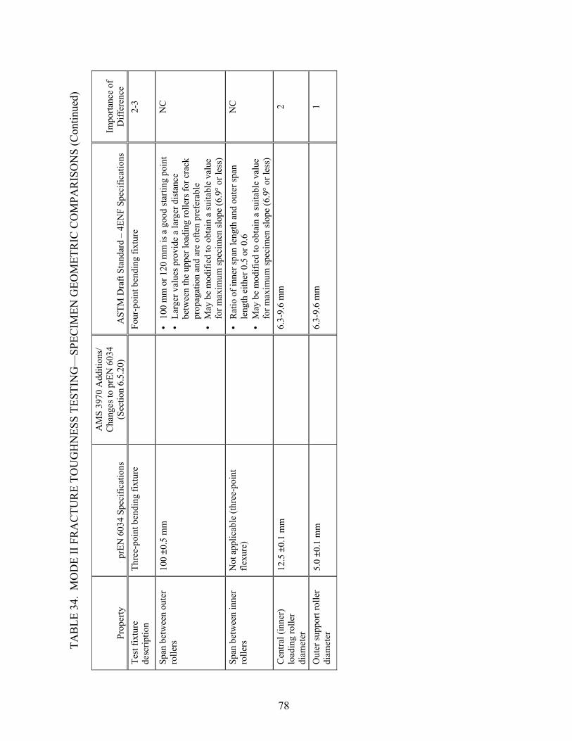
TAB
LE 3
4. M
OD
E II
FR
AC
TUR
E TO
UG
HN
ESS
TEST
ING
—SP
ECIM
EN G
EOM
ETR
IC C
OM
PAR
ISO
NS
(Con
tinue
d)
Prop
erty
pr
EN 6
034
Spec
ifica
tions
AM
S 39
70 A
dditi
ons/
C
hang
es to
prE
N 6
034
(Sec
tion
6.5.
20)
AST
M D
raft
Stan
dard
– 4
ENF
Spec
ifica
tions
Im
porta
nce
of
Diff
eren
ce
Test
fixt
ure
desc
riptio
n Th
ree-
poin
t ben
ding
fixt
ure
Fo
ur-p
oint
ben
ding
fixt
ure
2-3
Span
bet
wee
n ou
ter
rolle
rs
100
±0.5
mm
• • •
100
mm
or 1
20 m
m is
a g
ood
star
ting
poin
t La
rger
val
ues p
rovi
de a
larg
er d
ista
nce
betw
een
the
uppe
r loa
ding
rolle
rs fo
r cra
ck
prop
agat
ion
and
are
ofte
n pr
efer
able
M
ay b
e m
odifi
ed to
obt
ain
a su
itabl
e va
lue
for m
axim
um sp
ecim
en sl
ope
(6.9
° or l
ess)
NC
Span
bet
wee
n in
ner
rolle
rs
Not
app
licab
le (t
hree
-poi
nt
flexu
re)
• •
Rat
io o
f inn
er sp
an le
ngth
and
out
er sp
an
leng
th e
ither
0.5
or 0
.6
May
be
mod
ified
to o
btai
n a
suita
ble
valu
e fo
r max
imum
spec
imen
slop
e (6
.9° o
r les
s)
NC
Cen
tral (
inne
r)
load
ing
rolle
r di
amet
er
12.5
±0.
1 m
m
6.3-
9.6
mm
2
Out
er su
ppor
t rol
ler
diam
eter
5.
0 ±0
.1 m
m
6.3-
9.6
mm
1
78

TAB
LE 3
5. M
OD
E II
FR
AC
TUR
E TO
UG
HN
ESS
TEST
ING
—TE
ST P
RO
CED
UR
E C
OM
PAR
ISO
NS
Proc
edur
e pr
EN 6
034
Spec
ifica
tions
AM
S 39
70 A
dditi
ons/
C
hang
es to
prE
N 6
034
(Sec
tion
6.5.
20)
AST
M D
raft
Stan
dard
– 4
ENF
Spec
ifica
tions
Im
porta
nce
of
Diff
eren
ce
Load
indi
cato
r A
ccur
ate
to w
ithin
1%
in th
e lo
ad ra
nge
used
A
ccur
acy
over
the
load
rang
e(s)
of i
nter
est o
f with
in
±1%
of t
he in
dica
ted
valu
e 0
Alig
nmen
t Pl
ace
the
spec
imen
in th
e te
st
fixtu
re to
pro
duce
an
initi
al
crac
k le
ngth
of 3
5 ±1
mm
M
ake
sure
that
the
mar
ks o
n ea
ch e
dge
of th
e sp
ecim
en a
re p
ositi
oned
app
ropr
iate
ly su
ch th
at th
e sp
ecim
en a
nd fi
xtur
e ar
e al
igne
d
1
Test
spee
d 1
mm
/min
Con
stan
t cro
sshe
ad ra
te b
etw
een
0.1
and
1 m
m/m
in
1-2
Sam
plin
g N
ot sp
ecifi
ed
Six
spec
imen
s (A
MS
3970
-2)
At l
east
five
spec
imen
s 2
Spec
imen
co
nditi
onin
g
Spec
imen
con
ditio
ning
and
te
stin
g at
23°
±2°
C a
nd 5
0%
±5%
rela
tive
hum
idity
St
ore
and
test
spec
imen
s at s
tand
ard
labo
rato
ry
atm
osph
ere:
23°
±3°
C a
nd 5
0% ±
10%
rela
tive
hum
idity
1
Mea
sure
men
t of
spec
imen
wid
th
Ver
nier
cal
iper
acc
urat
e to
the
near
est 0
.1 m
m
• •
Mic
rom
eter
with
flat
anv
il ac
cura
te to
with
in 1
% o
f sp
ecim
en w
idth
(~±2
5 µm
) M
easu
re a
t thr
ee p
oint
s alo
ng th
e le
ngth
of t
he
spec
imen
in w
hich
the
dela
min
atio
n w
ill b
e pr
opag
ated
and
repo
rt av
erag
e va
lue
1
Mea
sure
men
t of
spec
imen
leng
th
Ver
nier
cal
iper
acc
urat
e to
the
near
est 0
.1 m
m
M
easu
re to
the
near
est 1
mm
1
Mea
sure
men
t of
spec
imen
thic
knes
s A
min
imum
of t
hree
m
easu
rem
ents
dis
tribu
ted
over
th
e sp
ecim
en u
sing
a fl
at-f
ace
mic
rom
eter
acc
urat
e to
the
near
est 0
.1 m
m
• • •
Mic
rom
eter
with
dou
ble-
ball
inte
rfac
e ac
cura
te to
w
ithin
1%
of s
peci
men
thic
knes
s (~±
2.5
µm) o
n irr
egul
ar su
rfac
es
Mic
rom
eter
with
flat
anv
il ac
cura
te to
with
in 1
% o
f sp
ecim
en th
ickn
ess (
~±2.
5 µm
) on
very
smoo
th-
tool
ed su
rfac
es
Mea
sure
thic
knes
s of e
ach
spec
imen
at s
ix p
oint
s an
d re
port
aver
age
valu
e
1
79
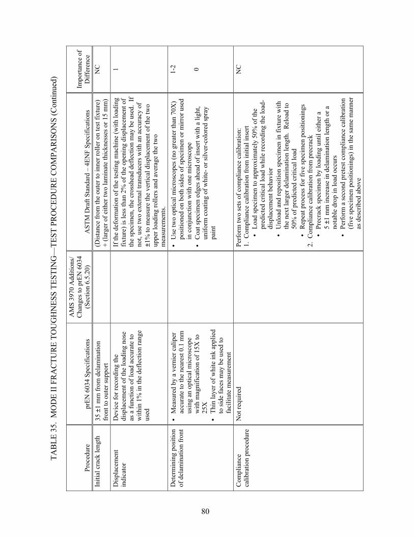
TAB
LE 3
5. M
OD
E II
FR
AC
TUR
E TO
UG
HN
ESS
TEST
ING
—TE
ST P
RO
CED
UR
E C
OM
PAR
ISO
NS
(Con
tinue
d)
Proc
edur
e pr
EN 6
034
Spec
ifica
tions
AM
S 39
70 A
dditi
ons/
C
hang
es to
prE
N 6
034
(Sec
tion
6.5.
20)
AST
M D
raft
Stan
dard
– 4
ENF
Spec
ifica
tions
Im
porta
nce
ofD
iffer
ence
In
itial
cra
ck le
ngth
35
±1
mm
from
del
amin
atio
n fr
ont t
o ou
ter s
uppo
rt
(Dis
tanc
e fr
om th
e ou
ter t
o in
ner r
olle
r on
test
fixt
ure)
+
(larg
er o
f eith
er tw
o la
min
ate
thic
knes
ses o
r 15
mm
) N
C
Dis
plac
emen
t in
dica
tor
Dev
ice
for r
ecor
ding
the
disp
lace
men
t of t
he lo
adin
g no
se
as a
func
tion
of lo
ad a
ccur
ate
to
with
in 1
% in
the
defle
ctio
n ra
nge
used
If
the
defo
rmat
ion
of th
e te
stin
g m
achi
ne (w
ith lo
adin
g fix
ture
) is l
ess t
han
2% o
f the
ope
ning
dis
plac
emen
t of
the
spec
imen
, the
cro
sshe
ad d
efle
ctio
n m
ay b
e us
ed.
If
not,
use
two
exte
rnal
tran
sduc
ers w
ith a
n ac
cura
cy o
f ±1
% to
mea
sure
the
verti
cal d
ispl
acem
ent o
f the
two
uppe
r loa
ding
rolle
rs a
nd a
vera
ge th
e tw
o m
easu
rem
ents
.
1
Det
erm
inin
g po
sitio
n of
del
amin
atio
n fr
ont
• •
• •
Mea
sure
d by
a v
erni
er c
alip
er
accu
rate
to th
e ne
ares
t 0.1
mm
us
ing
an o
ptic
al m
icro
scop
e w
ith m
agni
ficat
ion
of 1
5X to
25
X
Thin
laye
r of w
hite
ink
appl
ied
to si
de fa
ces m
ay b
e us
ed to
fa
cilit
ate
mea
sure
men
t
U
se tw
o op
tical
mic
rosc
opes
(no
grea
ter t
han
70X
) po
sitio
ned
on b
oth
side
s of s
peci
men
or m
irror
use
d in
con
junc
tion
with
one
mic
rosc
ope
Coa
t spe
cim
en e
dges
ahe
ad o
f ins
ert w
ith a
ligh
t, un
iform
coa
ting
of w
hite
- or s
ilver
-col
ored
spra
y pa
int
1-2 0
Com
plia
nce
calib
ratio
n pr
oced
ure
Not
requ
ired
Pe
rfor
m tw
o se
ts o
f com
plia
nce
calib
ratio
n:
1. C
ompl
ianc
e ca
libra
tion
from
initi
al in
sert
•
Load
spec
imen
to a
ppro
xim
atel
y 50
% o
f the
pr
edic
ted
criti
cal l
oad
whi
le re
cord
ing
the
load
-di
spla
cem
ent b
ehav
ior
• • •
Unl
oad
and
repo
sitio
n sp
ecim
en in
fixt
ure
with
th
e ne
xt la
rger
del
amin
atio
n le
ngth
. R
eloa
d to
50
% o
f pre
dict
ed c
ritic
al lo
ad
Rep
eat p
roce
ss fo
r fiv
e sp
ecim
en p
ositi
onin
gs
2. C
ompl
ianc
e ca
libra
tion
from
pre
crac
k
• Pr
ecra
ck sp
ecim
en b
y lo
adin
g un
til e
ither
a
5 ±1
mm
incr
ease
in d
elam
inat
ion
leng
th o
r a
nota
ble
drop
in lo
ad o
ccur
s Pe
rfor
m a
seco
nd p
rete
st c
ompl
ianc
e ca
libra
tion
(fiv
e sp
ecim
en p
ositi
onin
gs) i
n th
e sa
me
man
ner
as d
escr
ibed
abo
ve
NC
80

TAB
LE 3
5. M
OD
E II
FR
AC
TUR
E TO
UG
HN
ESS
TEST
ING
—TE
ST P
RO
CED
UR
E C
OM
PAR
ISO
NS
(Con
tinue
d)
Proc
edur
e pr
EN 6
034
Spec
ifica
tions
AM
S 39
70 A
dditi
ons/
C
hang
es to
prE
N 6
034
(Sec
tion
6.5.
20)
AST
M D
raft
Stan
dard
– 4
ENF
Spec
ifica
tions
Im
porta
nce
of
Diff
eren
ce
Prec
rack
ing
Prod
uce
initi
al c
rack
in a
de
fined
Mod
e I p
roce
dure
(E
N 6
033)
or c
ut sp
ecim
ens
from
the
resi
dual
par
t of G
IC
spec
imen
test
ed o
r at l
east
lo
aded
and
cra
cked
per
EN
603
3
Pr
ecra
ck sp
ecim
en b
y lo
adin
g un
til e
ither
a 5
±1
mm
in
crea
se in
del
amin
atio
n le
ngth
or a
not
able
dro
p in
lo
ad o
ccur
s
2-3
Load
ing
proc
edur
e • •
• •
Load
the
spec
imen
, opt
ical
ly
obse
rvin
g th
e cr
ack
tip to
de
tect
the
crac
k pr
opag
atio
n on
set
Rec
ord
the
criti
cal l
oad
at
dela
min
atio
n cr
ack
onse
t and
st
op th
e lo
adin
g as
soon
as
evid
ence
of c
rack
pr
opag
atio
n ha
s bee
n co
nfirm
ed b
y a
smal
l loa
d dr
op
Lo
ad sp
ecim
en u
ntil
eith
er a
5 ±
1 m
m in
crea
se in
de
lam
inat
ion
leng
th fr
om p
recr
ack
or a
not
able
dro
p in
load
occ
urs
Split
ope
n sp
ecim
en a
fter t
est t
o in
spec
t qua
lity
and
shap
e of
inse
rt an
d pr
ecra
ck
2
81

TAB
LE 3
6. M
OD
E II
FR
AC
TUR
E TO
UG
HN
ESS
TEST
ING
—D
ATA
RED
UC
TIO
N/R
EPO
RTI
NG
CO
MPA
RIS
ON
S
Qua
ntity
pr
EN 6
034
Spec
ifica
tions
AM
S 39
70
Add
ition
s/C
hang
es to
pr
EN 6
034
(Sec
tion
6.5.
20)
AST
M D
raft
Stan
dard
– 4
ENF
Spec
ifica
tions
Im
porta
nce
of
Diff
eren
ce
Mod
e II
frac
ture
to
ughn
ess,
GII
C
Ref
erre
d to
as M
ode
II fr
actu
re
toug
hnes
s ene
rgy
23
3
2
34
12
9000
J/m
)a
L/
w (
d
P a
GII
C+
=
whe
re:
d =
disp
lace
men
t at c
rack
de
lam
inat
ion
onse
t, m
m
P =
criti
cal l
oad
to p
ropa
gate
the
crac
k, N
a
= in
itial
cra
ck le
ngth
, mm
w
= w
idth
of t
he sp
ecim
en, m
m
L =
span
leng
th, m
m
• •
Ref
erre
d to
as M
ode
II in
terla
min
ar fr
actu
re
toug
hnes
s Su
gges
ted
data
redu
ctio
n m
etho
d is
the
Com
plia
nce
Cal
ibra
tion
Met
hod:
B
m P
GII
C2
=2
whe
re: P =
load
at w
hich
frac
ture
occ
urs
B =
wid
th o
f spe
cim
en
m =
slop
e of
plo
t of c
ompl
ianc
e ve
rsus
de
lam
inat
ion
leng
th
• C
alcu
late
thre
e va
lues
of G
IIC:
GII
C v
alue
at o
nset
of n
onlin
earit
y in
load
vs
disp
lace
men
t cur
ve
GII
C v
alue
at v
isua
l ini
tiatio
n of
gro
wth
G
IIC v
alue
at 5
% o
ffse
t/max
imum
load
(5
%/m
ax)
3-4
Stat
istic
s N
ot a
ddre
ssed
Indi
vidu
al v
alue
s, m
ean
(ave
rage
) val
ue, s
tand
ard
devi
atio
n, a
nd c
oeff
icie
nt o
f var
iatio
n of
pro
perti
es
NC
Dat
a re
cord
ing
Load
vs d
ispl
acem
ent d
iagr
am
Lo
ad v
s dis
plac
emen
t cur
ve fo
r eac
h sp
ecim
en
Plot
s of c
ompl
ianc
e ve
rsus
del
amin
atio
n le
ngth
0 NC
82

TAB
LE 3
6. M
OD
E II
FR
AC
TUR
E TO
UG
HN
ESS
TEST
ING
—D
ATA
RED
UC
TIO
N/R
EPO
RTI
NG
CO
MPA
RIS
ON
S (C
ontin
ued)
Qua
ntity
pr
EN 6
034
Spec
ifica
tions
AM
S 39
70 A
dditi
ons/
C
hang
es to
prE
N 6
034
(Sec
tion
6.5.
20)
AST
M D
raft
Stan
dard
– 4
ENF
Spec
ifica
tions
Im
porta
nce
of
Diff
eren
ce
Oth
er re
porti
ng
requ
irem
ents
• • • • • • • • • • • • •
Dat
e/lo
catio
n of
test
M
ater
ial i
dent
ifica
tion/
info
Sp
ecim
en p
repa
ratio
n Sp
ecim
en d
imen
sion
s A
ging
/exp
osur
e co
nditi
ons
Indi
vidu
al te
st re
sults
and
ca
lcul
atio
ns
Te
st o
pera
tor
Inci
dent
s/de
viat
ions
Eq
uipm
ent u
sed
Test
met
hod
used
Se
t of t
ypic
al lo
ad v
s cr
ossh
ead
disp
lace
men
t cu
rves
(ind
ivid
ual c
urve
s ke
pt b
y te
st la
bora
tory
) M
ovem
ent o
f the
cra
ck to
pl
ies a
djac
ent t
o th
e m
idpl
ies
Test
par
amet
ers u
sed
D
ate/
loca
tion
of te
st
Mat
eria
l ide
ntifi
catio
n/in
fo
Spec
imen
pre
para
tion
Spec
imen
dim
ensi
ons
Con
ditio
ning
par
amet
ers a
nd re
sults
St
anda
rd d
ata
repo
rting
shee
t Ty
pe a
nd th
ickn
ess o
f ins
ert
Fibe
r vol
ume
frac
tion
V
oid
cont
ent
Span
leng
th o
f rol
ler s
uppo
rts
Load
rate
Te
mpe
ratu
re/h
umid
ity o
f tes
ting
lab
0 0 0 0 0 0 1 1 1 1 1 1 1 1 1 1 1 1 1
83

2.13 GLASS TRANSITION TEMPERATURE DETERMINATION.
The two AMS specifications considered, AMS 2980 and 3970, both provide additions and changes to procedure A of test method prEN 6032 (tables 37 through 39). Although not referred to in the AMS specifications, a draft ASTM standard for determining the glass transition temperature by dynamic mechanical analysis (DMA) is used as a comparison test method to prEN 6032. Note that this draft ASTM standard is very similar to SACMA 18R-94, “Glass Transition Temperature (Tg) Determination by DMA of Oriented Fiber-Resin Composites.” All three test methods detail the determination of the glass transition temperature using DMA. The size of the specimen used and the actual DMA test procedure are not specified in the two test methods compared, but rather are determined based on the manufacturer of the DMA equipment. Whereas the draft ASTM standard specifies two specimens, prEN 6032 specifies three specimens. AMS 2980 and 3970 specify six specimens per test condition. Other differences in test procedures and data reduction/reporting requirements are of minimal significance. Overall, it is believed that differences in DMA equipment produced by different manufacturers may produce more significant variability in test results than the parameters from the two test methods reviewed in the following tables.
84

TAB
LE 3
7. G
LASS
TR
AN
SITI
ON
TEM
PER
ATU
RE
TEST
ING
—SP
ECIM
EN G
EOM
ETR
IC C
OM
PAR
ISO
NS
Prop
erty
pr
EN 6
032-
A
Spec
ifica
tions
AM
S 29
80/3
970
Add
ition
s/
Cha
nges
to p
rEN
603
2 (S
ectio
n 6.
5.5)
A
STM
Dra
ft St
anda
rd
(Tg b
y D
MA
) Spe
cific
atio
ns
Impo
rtanc
e of
D
iffer
ence
Sp
ecim
en la
y-up
0°
for t
ape,
war
p fo
r fab
ric
Lam
inat
e: [
(90/
0)] 4S
(A
MS
2980
-2)
Lam
inat
e: [
(0/9
0)] 4S
(A
MS
3970
-2)
Poly
mer
mat
rix c
ompo
site
s rei
nfor
ced
by
cont
inuo
us, o
rient
ed, h
igh-
mod
ulus
fibe
rs
1
Spec
imen
leng
th a
nd
wid
th
Act
ual
Acc
ordi
ng to
requ
irem
ents
of
the
test
equ
ipm
ent
• • •
Con
sult
inst
rum
ent m
anuf
actu
rer’
s m
anua
l A
span
-to-th
ickn
ess r
atio
gre
ater
than
te
n is
typi
cal
Typi
cal s
peci
men
size
: 25
mm
x 1
2 m
m x
1 m
m
1
85
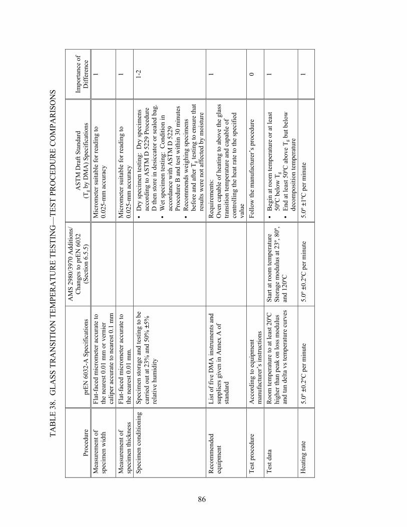
TAB
LE 3
8. G
LASS
TR
AN
SITI
ON
TEM
PER
ATU
RE
TEST
ING
—TE
ST P
RO
CED
UR
E C
OM
PAR
ISO
NS
Proc
edur
e pr
EN 6
032-
A S
peci
ficat
ions
AM
S 29
80/3
970
Add
ition
s/
Cha
nges
to p
rEN
603
2 (S
ectio
n 6.
5.5)
A
STM
Dra
ft St
anda
rd
(Tg b
y D
MA
) Spe
cific
atio
ns
Impo
rtanc
e of
D
iffer
ence
M
easu
rem
ent o
f sp
ecim
en w
idth
Fl
at-f
aced
mic
rom
eter
acc
urat
e to
th
e ne
ares
t 0.0
1 m
m o
r ver
nier
ca
liper
acc
urat
e to
nea
rest
0.1
mm
M
icro
met
er su
itabl
e fo
r rea
ding
to
0.02
5-m
m a
ccur
acy
1
Mea
sure
men
t of
spec
imen
thic
knes
s Fl
at-f
aced
mic
rom
eter
acc
urat
e to
th
e ne
ares
t 0.0
1 m
m.
M
icro
met
er su
itabl
e fo
r rea
ding
to
0.02
5-m
m a
ccur
acy
1 Sp
ecim
en c
ondi
tioni
ng
Spec
imen
stor
age
and
test
ing
to b
e ca
rrie
d ou
t at 2
3% a
nd 5
0% ±
5%
rela
tive
hum
idity
• • •
Dry
spec
imen
test
ing:
Dry
spec
imen
s ac
cord
ing
to A
STM
D 5
229
Proc
edur
e D
then
stor
e in
des
icca
tor o
r sea
led
bag.
W
et sp
ecim
en te
stin
g: C
ondi
tion
in
acco
rdan
ce w
ith A
STM
D 5
229
Proc
edur
e B
and
test
with
in 3
0 m
inut
es
Rec
omm
ends
wei
ghin
g sp
ecim
ens
befo
re a
nd a
fter T
g tes
ting
to e
nsur
e th
at
resu
lts w
ere
not a
ffec
ted
by m
oist
ure
1-2
Rec
omm
ende
d eq
uipm
ent
List
of f
ive
DM
A in
stru
men
ts a
nd
supp
liers
giv
en in
Ann
ex A
of
stan
dard
Req
uire
men
ts:
Ove
n ca
pabl
e of
hea
ting
to a
bove
the
glas
s tra
nsiti
on te
mpe
ratu
re a
nd c
apab
le o
f co
ntro
lling
the
heat
rate
to th
e sp
ecifi
ed
valu
e
1
Test
pro
cedu
re
Acc
ordi
ng to
equ
ipm
ent
man
ufac
ture
r’s i
nstru
ctio
ns
Fo
llow
the
man
ufac
ture
r’s p
roce
dure
0
Test
dat
a R
oom
tem
pera
ture
to a
t lea
st 2
0ºC
hi
gher
than
pea
k on
loss
mod
ulus
an
d ta
n de
lta v
s tem
pera
ture
cur
ves
Star
t at r
oom
tem
pera
ture
St
orag
e m
odul
us a
t 23º
, 80º
, an
d 12
0ºC
• •
Beg
in a
t roo
m te
mpe
ratu
re o
r at l
east
50
ºC b
elow
Tg
End
at le
ast 5
0ºC
abo
ve T
g but
bel
ow
deco
mpo
sitio
n te
mpe
ratu
re
1
Hea
ting
rate
5.
0º ±
0.2º
C p
er m
inut
e 5.
0º ±
0.2º
C p
er m
inut
e 5.
0º ±
1ºC
per
min
ute
1
86

TAB
LE 3
8. G
LASS
TR
AN
SITI
ON
TEM
PER
ATU
RE
TEST
ING
—TE
ST P
RO
CED
UR
E C
OM
PAR
ISO
NS
(Con
tinue
d)
Proc
edur
e pr
EN 6
032-
A S
peci
ficat
ions
AM
S 29
80/3
970
Add
ition
s/
Cha
nges
to p
rEN
603
2 (S
ectio
n 6.
5.5)
A
STM
Dra
ft St
anda
rd
(Tg b
y D
MA
) Spe
cific
atio
ns
Impo
rtanc
e of
D
iffer
ence
St
rain
rang
e N
ot sp
ecifi
ed
• •
• • W
ithin
line
ar v
isco
elas
tic
rang
e Le
ss th
an 1
000
µε
reco
mm
ende
d
Kep
t with
in th
e lin
ear v
isco
elas
tic ra
nge
Less
than
0.1
% ε
is st
anda
rd
1-2
Freq
uenc
y of
vib
ratio
n Fi
xed
at 1
Hz
(Met
hod
A)
1
Hz
0
Sam
plin
g Th
ree
spec
imen
s per
test
co
nditi
on
Six
spec
imen
s tes
ted
per
test
con
ditio
n (A
MS
2980
-2
and
AM
S 39
70-2
)
Two
test
spec
imen
s for
eac
h sa
mpl
e 1-
2
Equi
pmen
t cal
ibra
tion
Acc
ordi
ng to
the
man
ufac
ture
r’s
inst
ruct
ions
• • •
In a
ccor
danc
e w
ith A
STM
E 1
867
for
tem
pera
ture
sign
als
In a
ccor
danc
e w
ith th
e eq
uipm
ent
man
ufac
ture
r’s r
ecom
men
datio
n fo
r st
orag
e m
odul
us
Mus
t be
calib
rate
d in
the
sam
e m
ode
as
will
be
used
for t
estin
g
0
87

TAB
LE 3
9. G
LASS
TR
AN
SITI
ON
TEM
PER
ATU
RE
TEST
ING
—D
ATA
RED
UC
TIO
N/R
EPO
RTI
NG
CO
MPA
RIS
ON
S
Qua
ntity
pr
EN 6
032-
A S
peci
ficat
ions
AM
S 29
80/3
970
Add
ition
s/
Cha
nges
to p
rEN
603
2 (S
ectio
n 6.
5.5)
A
STM
Dra
ft St
anda
rd
(Tg b
y D
MA
) Spe
cific
atio
ns
Impo
rtanc
e of
Diff
eren
ce
Spec
imen
are
a, A
A
vera
ge o
f thr
ee w
idth
mea
sure
men
ts
times
ave
rage
of t
hree
thic
knes
s m
easu
rem
ents
N
otad
dres
sed
1
Req
uire
d pl
ot
Plot
: St
orag
e m
odul
us
L
oss m
odul
us
T
an d
elta
(opt
iona
l)
Line
ar (t
empe
ratu
re) a
nd lo
g (m
odul
us) s
cale
s
Log
of st
orag
e m
odul
us v
ersu
s lin
ear
tem
pera
ture
2
Gla
ss tr
ansi
tion
tem
pera
ture
• •
• • R
efer
red
to a
s Tg o
nset
Te
mpe
ratu
re a
t int
erse
ctio
n of
two
extra
pola
ted
tang
ents
to st
orag
e m
odul
us c
urve
: −
Tang
ent A
: lin
ear r
egio
n of
cur
ve
from
star
t tem
pera
ture
to b
egin
ning
of
dra
mat
ic sl
ope
of c
urve
(bef
ore
the
onse
t of t
he g
lass
tran
sitio
n ev
ent)
− Ta
ngen
t B:
tang
ent l
eft o
f the
po
int o
f inf
lect
ion
(Tg l
oss)
on
decr
easi
ng p
art o
f cur
ve (a
fter t
he
onse
t of t
he g
lass
tran
sitio
n ev
ent)
R
efer
red
to a
s Tg
Tem
pera
ture
at i
nter
sect
ion
of tw
o ta
ngen
ts to
stor
age
mod
ulus
cur
ve:
− Ta
ngen
t to
stor
age
mod
ulus
cur
ve
belo
w th
e tra
nsiti
on te
mpe
ratu
re
− Ta
ngen
t to
the
stor
age
mod
ulus
cu
rve
at th
e in
flect
ion
poin
t of t
he
mod
ulus
dro
p st
ep
1
T g lo
ss
Tem
pera
ture
cor
resp
ondi
ng to
the
max
imum
of t
he lo
ss m
odul
us c
urve
N
otad
dres
sed
NC
T g p
eak
• • O
ptio
nal
Tem
pera
ture
cor
resp
ondi
ng to
the
max
imum
val
ue o
f tan
del
ta
N
ot a
ddre
ssed
N
C
Slop
e an
gle
β • •
Opt
iona
l Sl
ope
of st
orag
e m
odul
us c
urve
re
pres
ente
d by
tang
ent A
(Tg o
nset
de
term
inat
ion)
N
ot a
ddre
ssed
N
C
88

TAB
LE 3
9. G
LASS
TR
AN
SITI
ON
TEM
PER
ATU
RE
TEST
ING
—D
ATA
RED
UC
TIO
N/R
EPO
RTI
NG
CO
MPA
RIS
ON
S (C
ontin
ued)
Qua
ntity
pr
EN 6
032-
A S
peci
ficat
ions
AM
S 29
80/3
970
Add
ition
s/
Cha
nges
to p
rEN
603
2 (S
ectio
n 6.
5.5)
A
STM
Dra
ft St
anda
rd
(Tg b
y D
MA
) Spe
cific
atio
ns
Impo
rtanc
e of
Diff
eren
ce
Qua
ntita
tive
chec
k T g
resu
lts sh
ould
be
with
in 2
.0ºC
of
thei
r mea
n. I
f gre
ater
, res
ults
shou
ld b
e sc
rutin
ized
for a
ccep
tabi
lity.
Not
addr
esse
dN
C
Stat
istic
s In
divi
dual
val
ues f
or e
ach
spec
imen
, m
ean
valu
e of
Tg r
esul
ts (f
or
quan
titat
ive
chec
k)
Not
addr
esse
dN
C
Oth
er re
porti
ng
requ
irem
ents
M
ater
ial i
dent
ifica
tion
Spec
imen
dim
ensi
ons
Equi
pmen
t use
d A
ging
/exp
osur
e co
nditi
ons
Stra
in fr
eque
ncy
Dat
e/lo
catio
n of
test
Te
st o
pera
tor
Dis
plac
emen
t am
plitu
de a
nd st
rain
rate
In
cide
nts/
devi
atio
ns
Spec
imen
pre
para
tion
Test
par
amet
ers u
sed
• • • • •
• • • • • • • • • • • • •
Tran
sduc
ers a
nd
cont
rolle
rs
Perc
ent c
hang
e in
stor
age
mod
ulus
at 8
0º a
nd 1
20ºC
re
lativ
e to
23º
C
Lo
adin
g m
ode
Stra
in ra
nge
Purg
e ga
s and
flow
rate
Mat
eria
l ide
ntifi
catio
n Sp
ecim
en d
imen
sion
s Eq
uipm
ent u
sed
Spec
imen
con
ditio
ning
his
tory
Fr
eque
ncy
of te
st
Dat
e of
test
Te
st o
pera
tor
Def
orm
atio
n am
plitu
de o
r stra
in
Dev
iatio
ns fr
om te
st m
etho
d C
ure
or p
roce
ss c
ycle
Spec
imen
con
ditio
ning
his
tory
Spec
imen
load
ing
cond
ition
and
cl
ampi
ng d
etai
ls
Flow
rate
of t
he p
urge
gas
0 0 0 0 0 0 0 0 0 1 1 1 1 1 1 1
89
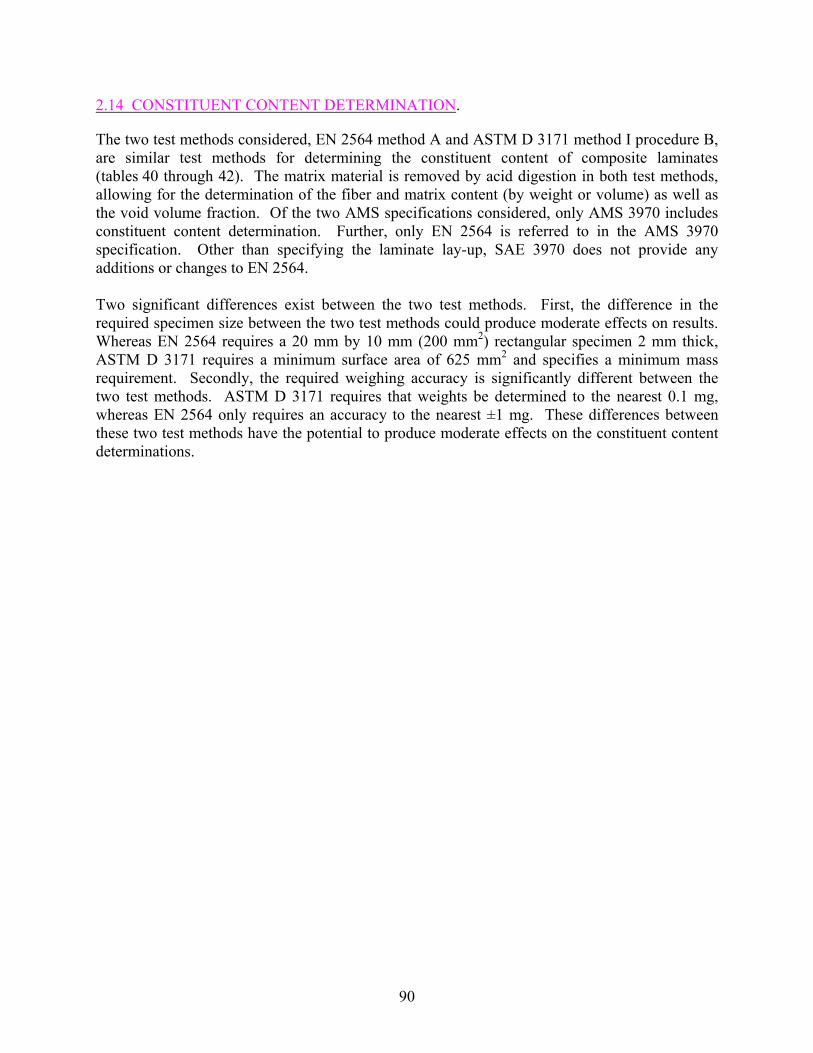
2.14 CONSTITUENT CONTENT DETERMINATION.
The two test methods considered, EN 2564 method A and ASTM D 3171 method I procedure B, are similar test methods for determining the constituent content of composite laminates (tables 40 through 42). The matrix material is removed by acid digestion in both test methods, allowing for the determination of the fiber and matrix content (by weight or volume) as well as the void volume fraction. Of the two AMS specifications considered, only AMS 3970 includes constituent content determination. Further, only EN 2564 is referred to in the AMS 3970 specification. Other than specifying the laminate lay-up, SAE 3970 does not provide any additions or changes to EN 2564. Two significant differences exist between the two test methods. First, the difference in the required specimen size between the two test methods could produce moderate effects on results. Whereas EN 2564 requires a 20 mm by 10 mm (200 mm2) rectangular specimen 2 mm thick, ASTM D 3171 requires a minimum surface area of 625 mm2 and specifies a minimum mass requirement. Secondly, the required weighing accuracy is significantly different between the two test methods. ASTM D 3171 requires that weights be determined to the nearest 0.1 mg, whereas EN 2564 only requires an accuracy to the nearest ±1 mg. These differences between these two test methods have the potential to produce moderate effects on the constituent content determinations.
90

TAB
LE 4
0. C
ON
STIT
UEN
T C
ON
TEN
T—SP
ECIM
EN G
EOM
ETR
IC C
OM
PAR
ISO
NS
Prop
erty
EN
256
4 M
etho
d A
Spe
cific
atio
ns
AM
S 39
70 A
dditi
ons/
C
hang
es to
EN
256
4 (S
ectio
n 6.
6.3)
A
STM
D 3
171
Proc
edur
e B
Spe
cific
atio
ns
Impo
rtanc
e of
D
iffer
ence
La
min
ate
lay-
up
Not
spec
ified
[(
90/0
)]6S
[(
45/-4
5)/(-
45/4
5)] 2
S (A
MS
3970
-2)
Not
spec
ified
0
Test
spec
imen
shap
e an
d si
ze
• • •
• • • •
Rec
tang
ular
, 20
mm
x 1
0 m
m
Thic
knes
s of 2
mm
Sp
ecim
ens o
f diff
eren
t di
men
sion
may
be
used
subj
ect
to a
gree
men
t of u
ser a
nd
man
ufac
ture
r
M
inim
um m
ass o
f 0.5
g fo
r con
stitu
ent
volu
me
only
M
inim
um m
ass o
f 1.0
g if
voi
d co
nten
t is
to b
e ob
tain
ed
Min
imum
spec
imen
surf
ace
area
of
625
mm
2 R
ough
ly re
ctan
gula
r in
dim
ensi
ons
3
Oth
er te
st sp
ecim
en
requ
irem
ents
C
ut a
t lea
st 1
0 m
m fr
om e
dges
of
lam
inat
e
Cut
ting
mus
t not
cau
se th
e sp
ecim
en to
fr
ay
1
91

TAB
LE 4
1. C
ON
STIT
UEN
T C
ON
TEN
T—TE
ST P
RO
CED
UR
E C
OM
PAR
ISO
NS
Prop
erty
EN
256
4 M
etho
d A
Spe
cific
atio
ns
AM
S 39
70 A
dditi
ons/
C
hang
es to
EN
256
4 (S
ectio
n 6.
6.3)
A
STM
D 3
171
Proc
edur
e B
Spe
cific
atio
ns
Impo
rtanc
e of
D
iffer
ence
Sa
mpl
ing
Min
imum
of t
hree
spec
imen
s eve
nly
dist
ribut
ed in
the
lam
inat
e
Min
imum
of t
hree
spec
imen
s 0
Dry
ing
proc
edur
e D
ry in
des
icca
tor u
ntil
diff
eren
ce in
m
ass o
f suc
cess
ive
wei
ghtin
gs is
less
th
an 2
mg
D
ry sp
ecim
ens t
o eq
uilib
rium
con
ditio
n in
ac
cord
ance
with
D 5
229
proc
edur
e D
1
Wei
ghin
g ac
cura
cy
Wei
gh to
±1
mg
W
eigh
eac
h sp
ecim
en to
the
near
est 0
.000
1 g
(0.1
mg)
3
Den
sity
m
easu
rem
ent
Det
erm
ine
spec
imen
den
sity
in
acco
rdan
ce w
ith IS
O 1
183
met
hod
A
D
eter
min
e sp
ecim
en d
ensi
ty in
acc
orda
nce
with
D 7
92 o
r D 1
505
1-2
Aci
d di
gest
ion
proc
edur
e
• • • • • • • • • • •
• • • • • • • • •
Dry
the
sint
ered
gla
ss c
ruci
ble
Plac
e sp
ecim
en in
flas
k A
dd 2
0 m
l of s
ulph
uric
aci
d
Hea
t to
160°
±10
°C u
ntil
acid
be
gins
to fu
me,
then
dis
cont
inue
he
atin
g D
rip o
f hyd
roge
n pe
roxi
de so
lutio
n in
to a
cid
until
solu
tion
beco
mes
and
re
mai
ns c
lear
C
ool s
olut
ion
and
pour
into
bea
ker
cont
aini
ng 1
00 m
l of d
istil
led
wat
er
Filte
r con
tent
s thr
ough
sint
ered
gl
ass c
ruci
ble
Was
h w
ith 1
0 m
l ace
tone
D
ry c
ruci
ble/
cont
ents
at 1
20°
±10°
C fo
r at l
east
45
min
C
ool c
ruci
ble/
cont
ents
in d
esic
cato
r fo
r 20
min
utes
W
eigh
cru
cibl
e/co
nten
ts to
±1
mg
W
eigh
spec
imen
Pl
ace
spec
imen
in b
eake
r A
dd a
min
imum
of 2
0 m
l of s
ulph
uric
aci
d an
d he
at u
ntil
mix
ture
star
ts to
fum
e
Add
35
ml o
f hyd
roge
n pe
roxi
de
Coo
l sol
utio
n an
d fil
ter c
onte
nts i
nto
prew
eigh
ed si
nter
ed g
lass
filte
r und
er
vacu
um
Was
h fib
ers t
hree
tim
es w
ith d
istil
led
wat
er
An
acet
one
was
h m
ay b
e us
ed a
s fin
al
was
h D
ry fi
lter/c
onte
nts a
t 100
°C fo
r 1 h
our o
r un
til sa
mpl
e is
drie
d C
ool t
o ro
om te
mpe
ratu
re in
des
icca
tor
Wei
gh c
ruci
ble
and
cont
ents
to th
e ne
ares
t 0.
0001
g (0
.1 m
g)
1
92
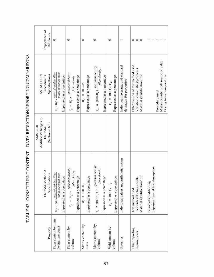
TAB
LE 4
2. C
ON
STIT
UEN
T C
ON
TEN
T—D
ATA
RED
UC
TIO
N/R
EPO
RTI
NG
CO
MPA
RIS
ON
S
Prop
erty
EN
256
4 M
etho
d A
Sp
ecifi
catio
ns
AM
S 39
70
Add
ition
s/C
hang
es to
EN
256
4 (S
ectio
n 6.
6.3)
AST
M D
317
1 Pr
oced
ure
B
Spec
ifica
tions
Im
porta
nce
of
Diff
eren
ce
Fibe
r con
tent
by
mas
s (w
eigh
t per
cent
) s
ecim
en m
asin
itial
sper
sidu
al fi
bm
ass o
f re
Wf
10
0
×
=
Expr
esse
d as
a p
erce
ntag
e
s
ecim
en m
asin
itial
sper
sidu
al fi
bm
ass o
f re
Wr
10
0
×
=
Expr
esse
d as
a p
erce
ntag
e
0
Fibe
r con
tent
by
volu
me
ityfib
er d
ensen
sity
spec
imen
d
W
V
ff
×=
Expr
esse
d as
a p
erce
ntag
e
ity
fiber
den
sensi
tysp
ecim
en d
W
Vr
r×
=
Expr
esse
d as
a p
erce
ntag
e
0
Mat
rix c
onte
nt b
y m
ass
fr
-W
W
100
=
Expr
esse
d as
a p
erce
ntag
e
rm
-W
W
100
=
Expr
esse
d as
a p
erce
ntag
e 0
Mat
rix c
onte
nt b
y vo
lum
e ity
fiber
den
sensi
tysp
ecim
en d
-W
V
fr
×=
)10
0(
Expr
esse
d as
a p
erce
ntag
e
ity
fiber
den
sdens
itysp
ecim
en
-W
V
rm
)10
0(
=
Expr
esse
d as
a p
erce
ntag
e
0
Voi
d co
nten
t by
volu
me
rf
o- V
-V
V
100
=
Expr
esse
d as
a p
erce
ntag
e
mr
o- V
-V
V
100
=
Expr
esse
d as
a p
erce
ntag
e 0
Stat
istic
s In
divi
dual
val
ues a
nd a
rithm
etic
mea
ns
In
divi
dual
, ave
rage
, and
stan
dard
de
viat
ion
for p
rope
rties
1
Oth
er re
porti
ng
requ
irem
ents
Te
st m
etho
d us
ed
Inci
dent
s aff
ectin
g re
sults
M
ater
ial i
dent
ifica
tion/
info
Pe
riod
of c
ondi
tioni
ng
Expo
sure
tim
e at
test
atm
osph
ere
D
ate/
revi
sion
of t
est m
etho
d us
ed
Var
iatio
ns/a
nom
alie
s/pr
oble
ms
Mat
eria
l ide
ntifi
catio
n/in
fo
Proc
edur
e us
ed
Mat
rix d
ensi
ty u
sed/
sour
ce o
f val
ue
Dry
ing
times
/tem
pera
ture
s
0 0 0 1 1 1 1 1
93

2.15 MOISTURE CONDITIONING PROCEDURE.
The two test methods considered, prEN 2823 and ASTM D 5229 procedure B, are similar procedures for conditioning specimens to be used in subsequent testing to determine the effects of moisture conditioning on physical or mechanical properties (tables 43 through 45). Note that ASTM D 5229 also specifies a fluid immersion procedure, which will be presented in the following section. Both test methods involve humidity aging at elevated temperature until moisture equilibrium is reached. The AMS 2980 and 3970 specifications provide extensive additions and changes to prEN 2823. Since humidity aging could cause postcuring effects on the specified materials, AMS 2980 specifies that DMA tests be performed on both water-immersed and humidity-aged specimens to determine which moisture conditioning procedure should be selected. In contrast, AMS 3970 specifies humidity aging only. Of the many differences noted between the two test methods and the additions and changes listed in the AMS specifications, none are expected to produce significant effects on results.
94
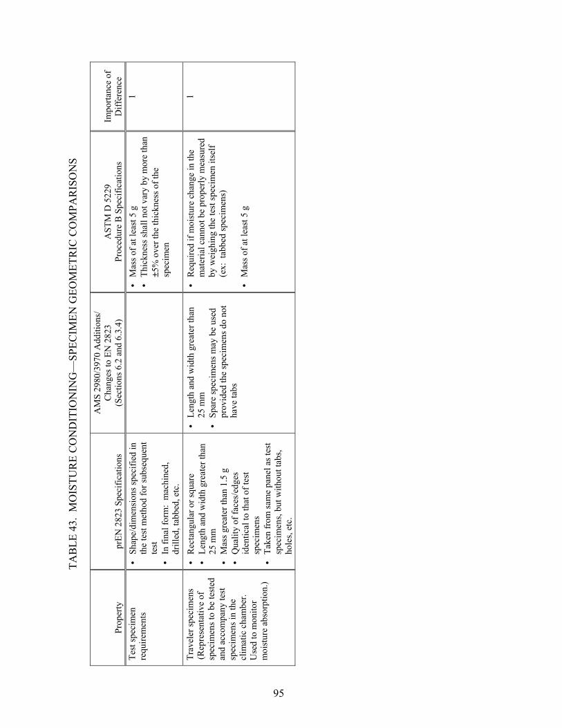
TAB
LE 4
3. M
OIS
TUR
E C
ON
DIT
ION
ING
—SP
ECIM
EN G
EOM
ETR
IC C
OM
PAR
ISO
NS
Prop
erty
pr
EN 2
823
Spec
ifica
tions
AM
S 29
80/3
970
Add
ition
s/
Cha
nges
to E
N 2
823
(Sec
tions
6.2
and
6.3
.4)
AST
M D
522
9 Pr
oced
ure
B S
peci
ficat
ions
Im
porta
nce
of
Diff
eren
ce
Test
spec
imen
re
quire
men
ts
• •
• • Sh
ape/
dim
ensi
ons s
peci
fied
in
the
test
met
hod
for s
ubse
quen
t te
st
In fi
nal f
orm
: m
achi
ned,
dr
illed
, tab
bed,
etc
.
M
ass o
f at l
east
5 g
Th
ickn
ess s
hall
not v
ary
by m
ore
than
±5
% o
ver t
he th
ickn
ess o
f the
sp
ecim
en
1
Trav
eler
spec
imen
s (R
epre
sent
ativ
e of
sp
ecim
ens t
o be
test
ed
and
acco
mpa
ny te
st
spec
imen
s in
the
clim
atic
cha
mbe
r.
Use
d to
mon
itor
moi
stur
e ab
sorp
tion.
)
• • • • •
• •
• •
Rec
tang
ular
or s
quar
e Le
ngth
and
wid
th g
reat
er th
an
25 m
m
Mas
s gre
ater
than
1.5
g
Qua
lity
of fa
ces/
edge
s id
entic
al to
that
of t
est
spec
imen
s Ta
ken
from
sam
e pa
nel a
s tes
t sp
ecim
ens,
but w
ithou
t tab
s, ho
les,
etc.
Leng
th a
nd w
idth
gre
ater
than
25
mm
Sp
are
spec
imen
s may
be
used
pr
ovid
ed th
e sp
ecim
ens d
o no
t ha
ve ta
bs
Req
uire
d if
moi
stur
e ch
ange
in th
e m
ater
ial c
anno
t be
prop
erly
mea
sure
d by
wei
ghin
g th
e te
st sp
ecim
en it
self
(ex:
tab
bed
spec
imen
s)
M
ass o
f at l
east
5 g
1
95

TAB
LE 4
4. M
OIS
TUR
E C
ON
DIT
ION
ING
—TE
ST P
RO
CED
UR
E C
OM
PAR
ISO
NS
Proc
edur
e pr
EN 2
823
Spec
ifica
tions
A
MS
2980
/397
0 A
dditi
ons/
Cha
nges
to
EN
282
3 (S
ectio
ns 6
.2 a
nd 6
.3.4
) A
STM
D 5
229
Proc
edur
e B
Spe
cific
atio
ns
Impo
rtanc
e of
D
iffer
ence
D
eter
min
atio
n of
wet
co
nditi
onin
g pr
oced
ures
Hum
idity
age
d • •
Hum
idity
age
d or
flui
d im
mer
sion
A
MS
2980
: H
umid
ity a
ging
is
expe
cted
to g
ive
post
cure
eff
ects
. Pe
rfor
m sc
reen
ing
test
pro
gram
(d
escr
ibed
in A
MS
2980
-2).
Hum
idity
age
d 1
Stor
age
cond
ition
s and
tim
es d
urin
g pa
nel,
subp
anel
, and
sp
ecim
en
man
ufac
turin
g
Spec
imen
s sha
ll no
t und
ergo
any
sp
ecia
l con
ditio
ning
bef
ore
expo
sure
• •
Stor
age
at 2
3° ±
5°C
in m
oist
ure-
proo
f bag
with
des
icca
nt
Perm
itted
ope
n tim
e fo
r spe
cim
en
man
ufac
turin
g is
14
days
at
ambi
ent c
ondi
tion
Not
add
ress
ed
NC
Clim
atic
cha
mbe
r C
apab
le o
f kee
ping
the
spec
ified
te
mpe
ratu
re to
with
in ±
1°C
and
re
lativ
e hu
mid
ity to
with
in ±
3%
C
apab
le o
f mai
ntai
ning
the
requ
ired
tem
pera
ture
to w
ithin
±1°
C a
nd
rela
tive
hum
idity
to w
ithin
±3%
0
Num
ber o
f tra
vele
r sp
ecim
ens
3
31
1-2
Mea
sure
men
t of
spec
imen
dim
ensi
ons
Not
add
ress
ed
• • •
Follo
win
g an
y pr
econ
ditio
ning
an
d ag
ain
afte
r agi
ng p
roce
dure
Th
ickn
ess:
ave
rage
of
mea
sure
men
ts a
t thr
ee o
r mor
e lo
catio
ns w
ith a
n ac
cura
cy o
f ±1%
or
bet
ter
Side
dim
ensi
ons:
nom
inal
di
men
sion
s mea
sure
d to
the
near
est 1
.0 m
m
NC
Agi
ng p
roce
dure
A
ging
in h
umid
ity c
ham
ber a
t el
evat
ed te
mpe
ratu
re
• •
Agi
ng in
hum
idity
cha
mbe
r or
imm
ersi
on in
wat
er a
t ele
vate
d te
mpe
ratu
re (A
MS
2980
-2)
Agi
ng in
hum
idity
cha
mbe
r at
elev
ated
tem
pera
ture
(AM
S 39
70)
Agi
ng in
hum
idity
cha
mbe
r at
elev
ated
tem
pera
ture
1
96

TAB
LE 4
4. M
OIS
TUR
E C
ON
DIT
ION
ING
—TE
ST P
RO
CED
UR
E C
OM
PAR
ISO
NS
(Con
tinue
d)
Proc
edur
e pr
EN 2
823
Spec
ifica
tions
A
MS
2980
/397
0 A
dditi
ons/
Cha
nges
to
EN
282
3 (S
ectio
ns 6
.2 a
nd 6
.3.4
) A
STM
D 5
229
Proc
edur
e B
Spe
cific
atio
ns
Impo
rtanc
e of
D
iffer
ence
Te
mpe
ratu
re fo
r sp
ecim
en a
ging
70
° ±2°
C
(Che
ck th
at e
quili
briu
m c
ondi
tion
is
reac
hed
at th
is te
mpe
ratu
re (i
f not
, ch
oose
low
er te
mpe
ratu
re)
70° ±
2°C
(AM
S 29
80-2
and
397
0-2)
• •
Max
imum
for 1
21°C
cur
e ep
oxie
s:
70°C
M
axim
um fo
r 177
°C c
ure
epox
ies:
80
°C
1
Moi
stur
e co
nditi
on fo
r sp
ecim
en a
ging
• •
• •
• •
85%
+5/
-1%
rela
tive
hum
idity
(s
tand
ard)
95
% +
5/-1
% re
lativ
e hu
mid
ity
(opt
iona
l)
Hum
idity
age
d (A
MS
2980
-2 a
nd
3970
-2):
85%
±5%
rela
tive
hum
idity
(sta
ndar
d) o
r 95%
±5%
(o
ptio
nal)
Wat
er im
mer
sed
(AM
S 29
80-2
): to
tal i
mm
ersi
on
No
requ
ired
rela
tive
hum
idity
le
vel
Ref
eren
ce to
MIL
-HD
BK
-17B
: −
85%
±5%
rela
tive
hum
idity
co
nsid
ered
wor
st-c
ase
airc
raft
serv
ice
envi
ronm
ent
− Tw
o-st
ep a
ccel
erat
ed
cond
ition
ing
sche
mes
(95%
-98
% fo
llow
ed b
y lo
wer
leve
l) ca
n be
use
d −
Liqu
id im
mer
sion
not
eq
uiva
lent
to 1
00%
rela
tive
hum
idity
1-2
Dur
atio
n fo
r spe
cim
en
agin
g • • •
• •
• •
Bas
ed o
n sa
tisfy
ing
a m
inim
um
mas
s D
iffer
ence
bet
wee
n th
ree
succ
essi
ve w
eigh
ings
on
trave
ler
spec
imen
s Eq
uilib
rium
def
ined
as t
he p
oint
w
here
the
max
imum
diff
eren
ce in
m
ass (
betw
een
thre
e w
eigh
ings
) di
vide
d by
the
max
imum
mas
s is
≤ 5
× 10
-4
Hum
idity
age
d (A
MS
2980
-2 a
nd
3970
-2):
Unt
il sa
tura
tion
W
ater
imm
erse
d: (A
MS
2980
-2)
336
±16
hour
s
Unt
il ef
fect
ive
moi
stur
e eq
uilib
rium
is re
ache
d: d
efin
ed a
s th
e po
int w
here
the
aver
age
moi
stur
e co
nten
t of t
he m
ater
ial
chan
ges b
y le
ss th
an 0
.01%
with
in
the
span
of t
he re
fere
nce
time
perio
d (ti
me
inte
rval
bet
wee
n w
eigh
ings
) M
inim
um o
f thr
ee w
eigh
ings
ne
cess
ary:
pre
test
wei
ghin
g an
d tw
o fin
al w
eigh
ings
1-2
97

TAB
LE 4
4. M
OIS
TUR
E C
ON
DIT
ION
ING
—TE
ST P
RO
CED
UR
E C
OM
PAR
ISO
NS
(Con
tinue
d)
Proc
edur
e pr
EN 2
823
Spec
ifica
tions
A
MS
2980
/397
0 A
dditi
ons/
Cha
nges
to
EN
282
3 (S
ectio
ns 6
.2 a
nd 6
.3.4
) A
STM
D 5
229
Proc
edur
e B
Spe
cific
atio
ns
Impo
rtanc
e of
D
iffer
ence
Ti
me
inte
rval
bet
wee
n w
eigh
t gai
n m
easu
rem
ents
168
hour
s (7
days
)
• If
moi
stur
e di
ffus
ivity
Dz k
now
n,
the
grea
ter o
f:
0
.02(
thic
knes
s)2 /D
z (se
cond
s)
or 8
6,40
0 se
c (1
day
) •
If m
oist
ure
diff
usiv
ity D
z not
kn
own,
604
,000
sec
(7 d
ays)
1
Proc
edur
e fo
r wei
ght
gain
mea
sure
men
t • • •
• • • •
Rem
ove
trave
ler s
peci
men
s fro
m
clim
atic
cha
mbe
r and
wip
e to
re
mov
e co
nden
satio
n A
llow
spec
imen
s to
cool
to ro
om
tem
pera
ture
in a
seal
ed c
onta
iner
Im
med
iate
ly w
eigh
R
emov
e sp
ecim
en fr
om
cond
ition
ing
cham
ber a
nd p
lace
in
spec
imen
bag
unt
il it
reac
hes r
oom
te
mpe
ratu
re.
Rem
ove
and
wip
e to
re
mov
e su
rfac
e m
oist
ure.
Im
med
iate
ly w
eigh
to n
eare
st 0
.1
mg
Max
imum
30
min
/wei
ghin
g ou
t of
cond
ition
ing
cham
ber
Max
imum
5 m
in/w
eigh
ing
out o
f sp
ecim
en b
ag
1
Acc
urac
y of
wei
ght
gain
mea
sure
men
t 0.
1 m
g 0.
02%
(abs
olut
e)
• •
0.1
mg
for s
peci
men
mas
s be
twee
n 5
and
50 g
1.
0 m
g fo
r spe
cim
en m
ass g
reat
er
than
50
g
1
Det
erm
inat
ion
of
moi
stur
e ab
sorb
ed b
y sp
ecim
ens
Dry
trav
eler
spec
imen
s in
oven
: 72
hrs
at 5
0° ±
5°C
72
hrs
at 7
0° ±
5°C
re
quire
d tim
e at
90°
±5°
C to
obt
ain
a co
nsta
nt m
ass
N
ot a
ddre
ssed
as p
art o
f pro
cedu
re B
N
C
Stra
in g
age
bond
ing
Not
spec
ified
M
axim
um 1
hou
r at a
mbi
ent c
ondi
tion
Not
add
ress
ed
NC
Ope
n tim
e in
test
ca
bine
t N
ot sp
ecifi
ed
Max
imum
1 h
our a
t 23°
±2°
C
Not
add
ress
ed
NC
98
TAB
LE 4
4. M
OIS
TUR
E C
ON
DIT
ION
ING
—TE
ST P
RO
CED
UR
E C
OM
PAR
ISO
NS
(Con
tinue
d)
Proc
edur
e pr
EN 2
823
Spec
ifica
tions
A
MS
2980
/397
0 A
dditi
ons/
Cha
nges
to
EN
282
3 (S
ectio
ns 6
.2 a
nd 6
.3.4
) A
STM
D 5
229
Proc
edur
e B
Spe
cific
atio
ns
Impo
rtanc
e of
D
iffer
ence
Sp
ecim
en st
orag
e be
fore
test
ing
Spec
imen
may
be
mai
ntai
ned
for a
m
axim
um o
f 72
hour
s in
a se
aled
co
ntai
ner
• •
Hum
idity
age
d: (
AM
S 29
80-2
and
39
70-2
): 2
3° ±
5°C
wra
pped
in a
w
et to
wel
. M
axim
um ti
me
of 8
ho
urs.
Wat
er im
mer
sed:
(A
MS
2980
-2):
23° ±
5°C
in w
ater
bat
h or
wet
to
wel
. M
axim
um ti
me
of 8
hou
rs.
Not
add
ress
ed
NC
Test
ing
at a
mbi
ent
tem
pera
ture
afte
r ex
posu
re
Test
per
form
ed w
ithin
30
min
fo
llow
ing
rem
oval
from
stor
age
N
ot a
ddre
ssed
N
C
Test
ing
at
tem
pera
ture
s oth
er
than
am
bien
t afte
r ex
posu
re
• • •
Min
imiz
e tim
e be
twee
n pl
acin
g sp
ecim
en in
fixt
ure
and
com
plet
ing
the
test
Su
gges
ts le
ss th
an 1
5 m
in fo
r am
bien
t to
50°C
Su
gges
ts le
ss th
an 5
min
for
carb
on sp
ecim
ens f
rom
1-2
mm
th
ickn
ess a
nd fo
r tem
pera
ture
s ra
ngin
g fr
om 5
0°-1
00°C
N
ot a
ddre
ssed
N
C
99

TAB
LE 4
5. M
OIS
TUR
E C
ON
DIT
ION
ING
—D
ATA
RED
UC
TIO
N/R
EPO
RTI
NG
CO
MPA
RIS
ON
S
Qua
ntity
pr
EN 2
823
Spec
ifica
tions
AM
S 29
80/3
970
Add
ition
s/
Cha
nges
to E
N 2
823
(Sec
tions
6.2
and
6.3
.4)
AST
M D
522
9 Pr
oced
ure
B S
peci
ficat
ions
Im
porta
nce
of
Diff
eren
ce
Perc
enta
ge o
f abs
orbe
d m
oist
ure
Bas
ed o
n di
ffer
ence
in m
ean
of
wei
ghin
gs o
f tra
vele
r spe
cim
ens
betw
een
equi
libriu
m a
nd a
fter
dryi
ng
N
ot a
ddre
ssed
in p
roce
dure
B
NC
Stat
istic
s M
ean
valu
e of
trav
eler
spec
imen
w
eigh
ts
A
vera
ge, s
tand
ard
devi
atio
n, a
nd
coef
ficie
nt o
f var
iatio
n fo
r moi
stur
e pr
oper
ties (
for s
ampl
e po
pula
tions
of t
hree
or
mor
e)
1
Oth
er re
porti
ng
requ
irem
ents
• • • • • • • • •
• • • • •
• • • •
Test
met
hod
used
In
cide
nts a
ffec
ting
resu
lts
Mat
eria
l ide
ntifi
catio
n/in
fo
Tem
pera
ture
of c
ondi
tioni
ng
Ty
pe o
f tra
vele
r spe
cim
en
Leng
th o
f exp
osur
e M
etho
d of
stor
ing
spec
imen
s be
fore
test
ing
Tim
e sp
ecim
ens a
re
mai
ntai
ned
at te
st
tem
pera
ture
bef
ore
test
ing
Act
ual t
estin
g tim
e
Pa
nel c
urin
g da
te
Dia
gram
of w
eigh
t gai
n ve
rsus
agi
ng ti
me
Con
ditio
n an
d hi
stor
y of
sp
ecim
en b
efor
e ag
ing
Agi
ng e
quip
men
t and
pl
acem
ent o
f pan
els i
n th
e eq
uipm
ent
Equi
pmen
t con
trol d
iagr
am
abou
t agi
ng c
ondi
tions
and
tim
e
• Pr
oced
ure
used
V
aria
tions
/ano
mal
ies/
prob
lem
s M
ater
ial i
dent
ifica
tion/
info
Te
mpe
ratu
re u
sed
for c
ondi
tioni
ng
Pl
ots o
f per
cent
mas
s cha
nge
vers
us
(tim
e)½
0 0 0 0 1 1 1 1 1 1 1 1 1 1
100

TAB
LE 4
5. M
OIS
TUR
E C
ON
DIT
ION
ING
—D
ATA
RED
UC
TIO
N/R
EPO
RTI
NG
CO
MPA
RIS
ON
S (C
ontin
ued)
Qua
ntity
pr
EN 2
823
Spec
ifica
tions
AM
S 29
80/3
970
Add
ition
s/
Cha
nges
to E
N 2
823
(Sec
tions
6.2
and
6.3
.4)
AST
M D
522
9 Pr
oced
ure
B S
peci
ficat
ions
Im
porta
nce
of
Diff
eren
ce
Oth
er re
porti
ng
requ
irem
ents
(c
ontin
ued)
• • • • •
• • • • • • • • • • • • • • •
Pane
l cur
ing
date
D
iagr
am o
f wei
ght g
ain
vers
us a
ging
tim
e C
ondi
tion
and
hist
ory
of
spec
imen
bef
ore
agin
g A
ging
equ
ipm
ent a
nd
plac
emen
t of p
anel
s in
the
equi
pmen
t Eq
uipm
ent c
ontro
l dia
gram
ab
out a
ging
con
ditio
ns a
nd
time
Dat
e/lo
catio
n of
test
Te
st o
pera
tor
Lam
inat
e st
acki
ng se
quen
ce
Den
sity
, vol
ume
perc
ent r
einf
orce
men
t, vo
id c
onte
nt, a
nd a
vera
ge p
ly th
ickn
ess
Met
hod
of p
repa
ring
test
spec
imen
s C
alib
ratio
n da
tes/
met
hods
for
mea
sure
men
t and
test
equ
ipm
ent
Res
ults
of p
reco
nditi
onin
g Sp
ecim
en d
imen
sion
s prio
r to
and
follo
win
g m
oist
ure
cond
ition
ing
Type
of c
ham
ber u
sed
Moi
stur
e le
vel u
sed
for c
ondi
tioni
ng
Mea
sure
men
t tim
e in
terv
al
Tem
pera
ture
and
rela
tive
hum
idity
of t
he
test
ing
lab
Spec
imen
mas
s at e
ach
time
leve
l Pl
ots o
f per
cent
mas
s cha
nge
vers
us
(tim
e)½
Eq
uilib
rium
moi
stur
e co
nten
t, in
per
cent
1 1 1 1 1 1 1 1 1 1 1 1 1 1 1
101

2.16 FLUID IMMERSION PROCEDURE.
The two test methods considered, EN 2849 and ASTM D 5229 procedure B, both provide procedures for fluid immersion of specimens for use in subsequent testing to determine the effects of moisture conditioning on physical or mechanical properties (tables 46 through 48). Note that ASTM D 5229 is the same test method used for moisture conditioning through humidity aging, as discussed in the section 2.1.5. For fluid immersion, ASTM D 5229 procedure B requires that specimens be immersed until moisture equilibrium is obtained, and details a method of periodic weighings for establishing when equilibrium has been reached. In contrast, EN 2489 refers to the particular material standard to be used for subsequent testing for this information. Both the AMS 2980 and 3970 specifications provide extensive additions and changes to EN 2849 only. These specifications include detailed immersion procedures for specific fluids (water, fuel, solvent, hydraulic fluid, and hydraulic fluid/water mixture) as well as specimen storage positions during fabrication, prior to fluid immersion, and prior to subsequent material testing. Although many differences are noted between the two test methods and the additions and changes listed in the AMS specifications, none are expected to produce significant effects on results.
102

103
TA
BLE
46.
FLU
ID IM
MER
SIO
N M
ETH
OD
—SP
ECIM
EN G
EOM
ETR
IC C
OM
PAR
ISO
NS
Prop
erty
EN
248
9 Sp
ecifi
catio
ns
AM
S 29
80/3
970
Add
ition
s/
Cha
nges
to E
N 2
489
(S
ectio
ns 6
.2 a
nd 6
.3.3
) A
STM
D 5
229
Proc
edur
e B
Spe
cific
atio
ns
Impo
rtanc
e of
D
iffer
ence
Te
st sp
ecim
en
requ
irem
ents
Sh
ape/
dim
ensi
ons s
peci
fied
in th
e te
st m
etho
d
• • M
ass o
f at l
east
5 g
Th
ickn
ess s
hall
not v
ary
by m
ore
than
±5
% o
ver t
he th
ickn
ess o
f the
sp
ecim
en
1
Trav
eler
spec
imen
s (R
epre
sent
ativ
e of
sp
ecim
ens t
o be
test
ed
and
acco
mpa
ny te
st
spec
imen
s in
the
fluid
im
mer
sion
. U
sed
to
mon
itor f
luid
ab
sorp
tion.
)
Not
add
ress
ed
• •
• •
Leng
th a
nd w
idth
gre
ater
than
25
mm
Sp
are
spec
imen
s may
be
used
pr
ovid
ed th
e sp
ecim
ens d
o no
t ha
ve ta
bs
Req
uire
d if
moi
stur
e ch
ange
in th
e m
ater
ial c
anno
t be
prop
erly
mea
sure
d by
wei
ghin
g th
e te
st sp
ecim
en it
self
(ex:
tab
bed
spec
imen
s)
Mas
s of a
t lea
st 5
g
1
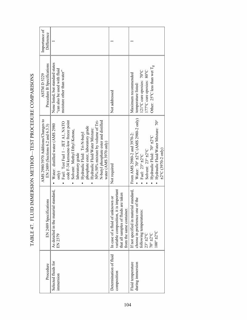
104
TA
BLE
47.
FLU
ID IM
MER
SIO
N M
ETH
OD
—TE
ST P
RO
CED
UR
E C
OM
PAR
ISO
NS
Proc
edur
e EN
248
9 Sp
ecifi
catio
ns
AM
S 29
80/3
970
Add
ition
s/C
hang
es to
EN
248
9 (S
ectio
ns 6
.2 a
nd 6
.3.3
) A
STM
D 5
229
Proc
edur
e B
Spe
cific
atio
ns
Impo
rtanc
e of
D
iffer
ence
Se
lect
ed fl
uids
for
imm
ersi
on
As d
etai
led
in th
e m
ater
ial s
tand
ard,
EN
237
9 • • • • •
Wat
er:
dist
illed
wat
er (A
MS
2980
on
ly)
Fuel
: Te
st F
uel 1
– JE
T A
1, N
ATO
co
de F
-34
kero
sene
-low
free
ze p
oint
So
lven
t: M
ethy
l Eth
yl K
eton
e,
labo
rato
ry g
rade
H
ydra
ulic
Flu
id:
Tri-N
-but
yl
phos
phat
e es
ter,
labo
rato
ry g
rade
H
ydra
ulic
Flu
id/W
ater
Mix
ture
: 50
%:5
0% m
ixtu
re b
y vo
lum
e of
Tri-
N-b
utyl
pho
spha
te e
ster
and
dis
tille
d w
ater
(AM
S 39
70 o
nly)
Non
e lis
ted,
but
stan
dard
stat
es
“can
als
o be
use
d w
ith fl
uid
moi
stur
e ot
her t
han
wat
er”
1
Det
erm
inat
ion
of fl
uid
com
posi
tion
In c
ase
of a
flui
d of
unk
now
n or
va
riabl
e co
mpo
sitio
n, it
is im
porta
nt
that
all
sam
ples
of f
luid
s are
take
n fr
om th
e sa
me
cont
aine
r.
Not
requ
ired
Not
add
ress
ed
1
Flui
d te
mpe
ratu
re
durin
g im
mer
sion
If
not
spec
ified
in m
ater
ial s
tand
ard,
ch
oose
in p
refe
renc
e on
e of
the
follo
win
g te
mpe
ratu
res:
23
° ±2°
C
70° ±
2°C
10
0° ±
2°C
From
AM
S 29
80-2
and
397
0-2:
•
Wat
er:
70° ±
2°C
(AM
S 29
80-2
onl
y)
• • • •
Fuel
: 23
° ±2°
C
Solv
ent:
23°
±2°
C
Hyd
raul
ic F
luid
: 70
° ±2°
C
Hyd
raul
ic F
luid
/Wat
er M
ixtu
re:
70°
±2°C
(397
0-2
only
)
Max
imum
reco
mm
ende
d te
mpe
ratu
re li
sted
: 12
1°C
cur
e ep
oxie
s: 7
0°C
17
7°C
cur
e ep
oxie
s: 8
0°C
O
ther
: 25
°C le
ss th
an w
et T
g
1
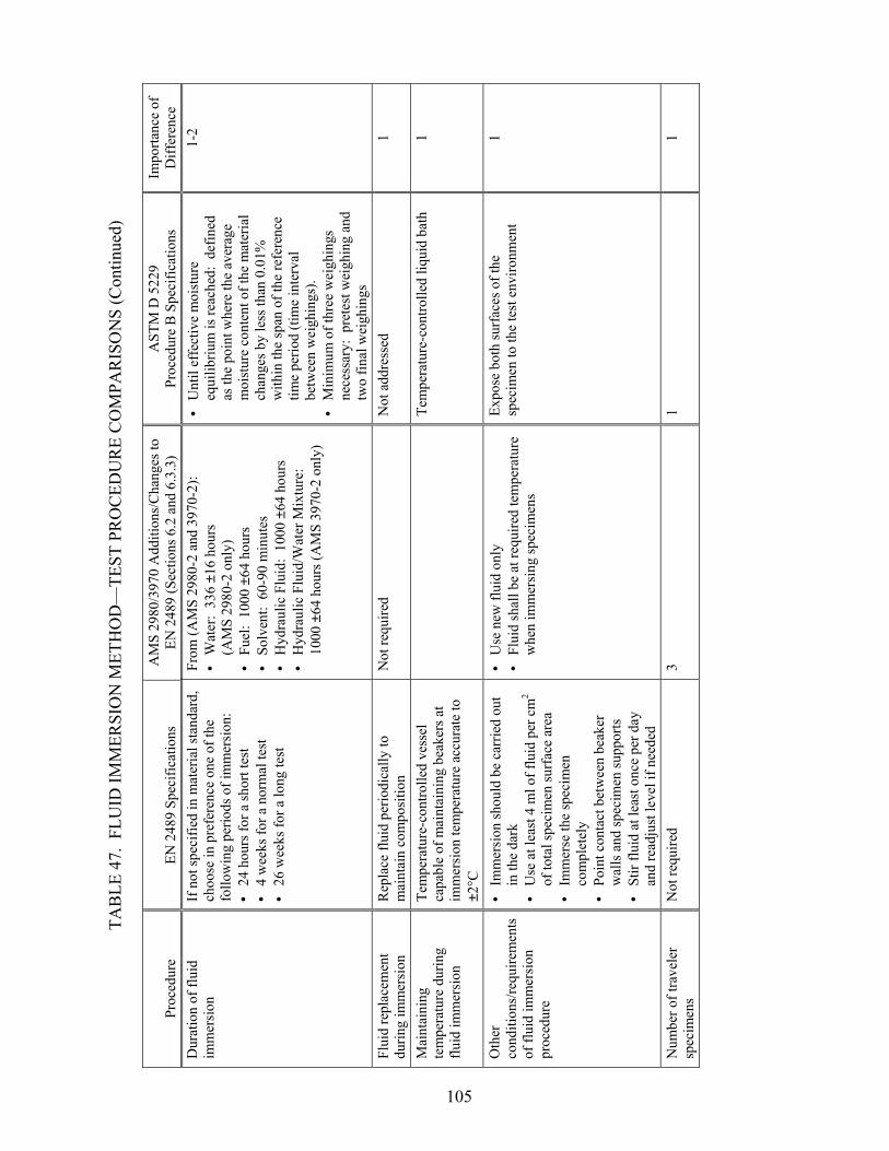
105
TA
BLE
47.
FLU
ID IM
MER
SIO
N M
ETH
OD
—TE
ST P
RO
CED
UR
E C
OM
PAR
ISO
NS
(Con
tinue
d)
Proc
edur
e EN
248
9 Sp
ecifi
catio
ns
AM
S 29
80/3
970
Add
ition
s/C
hang
es to
EN
248
9 (S
ectio
ns 6
.2 a
nd 6
.3.3
) A
STM
D 5
229
Proc
edur
e B
Spe
cific
atio
ns
Impo
rtanc
e of
D
iffer
ence
D
urat
ion
of fl
uid
imm
ersi
on
If n
ot sp
ecifi
ed in
mat
eria
l sta
ndar
d,
choo
se in
pre
fere
nce
one
of th
e fo
llow
ing
perio
ds o
f im
mer
sion
: •
24 h
ours
for a
shor
t tes
t • •
• • • •
• •
4 w
eeks
for a
nor
mal
test
26
wee
ks fo
r a lo
ng te
st
From
(AM
S 29
80-2
and
397
0-2)
: •
Wat
er:
336
±16
hour
s (A
MS
2980
-2 o
nly)
Fu
el:
1000
±64
hou
rs
Solv
ent:
60-
90 m
inut
es
Hyd
raul
ic F
luid
: 10
00 ±
64 h
ours
H
ydra
ulic
Flu
id/W
ater
Mix
ture
: 10
00 ±
64 h
ours
(AM
S 39
70-2
onl
y)
Unt
il ef
fect
ive
moi
stur
e eq
uilib
rium
is re
ache
d: d
efin
ed
as th
e po
int w
here
the
aver
age
moi
stur
e co
nten
t of t
he m
ater
ial
chan
ges b
y le
ss th
an 0
.01%
w
ithin
the
span
of t
he re
fere
nce
time
perio
d (ti
me
inte
rval
be
twee
n w
eigh
ings
). M
inim
um o
f thr
ee w
eigh
ings
ne
cess
ary:
pre
test
wei
ghin
g an
d tw
o fin
al w
eigh
ings
1-2
Flui
d re
plac
emen
t du
ring
imm
ersi
on
Rep
lace
flui
d pe
riodi
cally
to
mai
ntai
n co
mpo
sitio
n N
ot re
quire
d N
ot a
ddre
ssed
1
Mai
ntai
ning
te
mpe
ratu
re d
urin
g flu
id im
mer
sion
Tem
pera
ture
-con
trolle
d ve
ssel
ca
pabl
e of
mai
ntai
ning
bea
kers
at
imm
ersi
on te
mpe
ratu
re a
ccur
ate
to
±2°C
Te
mpe
ratu
re-c
ontro
lled
liqui
d ba
th
1
Oth
er
cond
ition
s/re
quire
men
ts
of fl
uid
imm
ersi
on
proc
edur
e
• • • • •
• • Im
mer
sion
shou
ld b
e ca
rrie
d ou
t in
the
dark
U
se a
t lea
st 4
ml o
f flu
id p
er c
m2
of to
tal s
peci
men
surf
ace
area
Im
mer
se th
e sp
ecim
en
com
plet
ely
Poin
t con
tact
bet
wee
n be
aker
w
alls
and
spec
imen
supp
orts
St
ir flu
id a
t lea
st o
nce
per d
ay
and
read
just
leve
l if n
eede
d
Use
new
flui
d on
ly
Flui
d sh
all b
e at
requ
ired
tem
pera
ture
w
hen
imm
ersi
ng sp
ecim
ens
Expo
se b
oth
surf
aces
of t
he
spec
imen
to th
e te
st e
nviro
nmen
t 1
Num
ber o
f tra
vele
r sp
ecim
ens
Not
requ
ired
3 1
1

106
TA
BLE
47.
FLU
ID IM
MER
SIO
N M
ETH
OD
—TE
ST P
RO
CED
UR
E C
OM
PAR
ISO
NS
(Con
tinue
d)
Proc
edur
e EN
248
9 Sp
ecifi
catio
ns
AM
S 29
80/3
970
Add
ition
s/C
hang
es to
EN
248
9 (S
ectio
ns 6
.2 a
nd 6
.3.3
) A
STM
D 5
229
Proc
edur
e B
Spe
cific
atio
ns
Impo
rtanc
e of
D
iffer
ence
V
isua
l ins
pect
ion
follo
win
g im
mer
sion
Ex
amin
e ea
ch sp
ecim
en a
fter
imm
ersi
on w
ith a
mag
nify
ing
glas
s, if
nece
ssar
y, w
hile
com
parin
g it
with
a sp
ecim
en th
at h
as n
ot b
een
imm
erse
d
Not
requ
ired
Not
add
ress
ed
NC
Stor
age
cond
ition
s and
tim
es d
urin
g pa
nel,
subp
anel
, and
spec
imen
m
anuf
actu
ring
Not
add
ress
ed
• •
Stor
age
at 2
3° ±
5°C
in m
oist
ure-
proo
f bag
with
des
icca
nt
Perm
itted
ope
n tim
e fo
r spe
cim
en
man
ufac
turin
g is
14
days
at a
mbi
ent
cond
ition
Not
add
ress
ed
NC
Spec
imen
stor
age
cond
ition
s and
tim
es
prio
r to
fluid
imm
ersi
on
Not
add
ress
ed
• •
Stor
age
at 2
3° ±
5°C
in m
oist
ure-
proo
f bag
with
des
icca
nt fo
r m
axim
um o
f 14
wee
ks a
fter p
anel
cu
ring
date
R
equi
rem
ent:
spec
imen
moi
stur
e co
nten
t of 0
.20%
by
wei
ght
Not
add
ress
ed
NC
Spec
imen
stor
age
befo
re te
stin
g If
dry
ing
spec
imen
follo
win
g im
mer
sion
, coo
l spe
cim
en in
a
seal
ed c
onta
iner
. C
arry
out
test
w
ithin
15
min
utes
follo
win
g th
e re
mov
al fr
om th
e se
aled
con
tain
er.
• • • • •
Wat
er:
23° ±
5°C
in w
ater
bat
h or
wet
to
wel
for 8
hou
rs m
ax. (
AM
S 29
80
only
) Fu
el:
23° ±
5°C
in fu
el b
ath
for 8
ho
urs m
ax.
Solv
ent:
no
stor
age
allo
wed
H
ydra
ulic
Flu
id:
23° ±
5°C
in
hydr
aulic
flui
d ba
th fo
r 8 h
ours
max
. H
ydra
ulic
Flu
id/W
ater
Mix
ture
: 23
° ±5
°C in
hyd
raul
ic fl
uid/
wat
er m
ixtu
re
bath
for 8
hou
rs m
ax. (
AM
S 39
70
only
)
Not
add
ress
ed
1

107
TA
BLE
47.
FLU
ID IM
MER
SIO
N M
ETH
OD
—TE
ST P
RO
CED
UR
E C
OM
PAR
ISO
NS
(Con
tinue
d)
Proc
edur
e EN
248
9 Sp
ecifi
catio
ns
AM
S 29
80/3
970
Add
ition
s/C
hang
es to
EN
248
9 (S
ectio
ns 6
.2 a
nd 6
.3.3
) A
STM
D 5
229
Proc
edur
e B
Spe
cific
atio
ns
Impo
rtanc
e of
D
iffer
ence
Pr
oced
ure
for w
eigh
t ga
in m
easu
rem
ent
Not
add
ress
ed
• •
• • • •
Rem
ove
trave
ler s
peci
men
s fro
m
fluid
and
wip
e to
rem
ove
cond
ensa
tion
Det
erm
ine
wei
ght g
ain
imm
edia
tely
Rem
ove
spec
imen
from
con
ditio
ning
ch
ambe
r (im
mer
sion
?) a
nd p
lace
in
spec
imen
bag
unt
il it
reac
hes r
oom
te
mpe
ratu
re.
Rem
ove
and
wip
e to
re
mov
e su
rfac
e m
oist
ure.
Im
med
iate
ly w
eigh
to n
eare
st 0
.1 m
g M
axim
um 3
0 m
in/w
eigh
ing
out o
f co
nditi
onin
g ch
ambe
r M
ax 5
min
/wei
ghin
g ou
t of
spec
imen
bag
1
Tim
e in
terv
al
betw
een
wei
ght g
ain
mea
sure
men
ts
Not
add
ress
ed
Bef
ore
and
imm
edia
tely
afte
r im
mer
sion
•
If m
oist
ure
diff
usiv
ity D
z is k
now
n,
the
grea
ter o
f:
0
.02(
thic
knes
s)2/
Dz (
seco
nds)
o
r 86,
400
sec
(1 d
ay)
• If
moi
stur
e di
ffus
ivity
Dz
is n
ot
know
n, 6
04,0
00 se
c (7
day
s)
1-2
Acc
urac
y of
wei
ght
gain
mea
sure
men
t N
ot a
ddre
ssed
0.
02%
(abs
olut
e)
• •
0.1
mg
for s
peci
men
mas
s bet
wee
n 5
and
50 g
1.
0 m
g fo
r spe
cim
en m
ass g
reat
er
than
50
g
1
Stra
in g
age
bond
ing
Not
add
ress
ed
Max
1 h
our a
t am
bien
t con
ditio
n N
ot a
ddre
ssed
N
C
Ope
n tim
e in
test
ca
bine
t N
ot a
ddre
ssed
M
ax 1
hou
r at 2
3° ±
2°C
N
ot a
ddre
ssed
N
C
Test
ing
at
tem
pera
ture
s oth
er
than
am
bien
t afte
r im
mer
sion
Mai
ntai
n sp
ecim
en in
test
fixt
ure
at
spec
ified
tem
pera
ture
for s
peci
fied
perio
d or
suff
icie
nt ti
me
for
spec
imen
to a
chie
ve sp
ecifi
ed
tem
pera
ture
with
out a
n un
acce
ptab
le lo
ss o
f abs
orbe
d flu
id
N
ot a
ddre
ssed
N
C
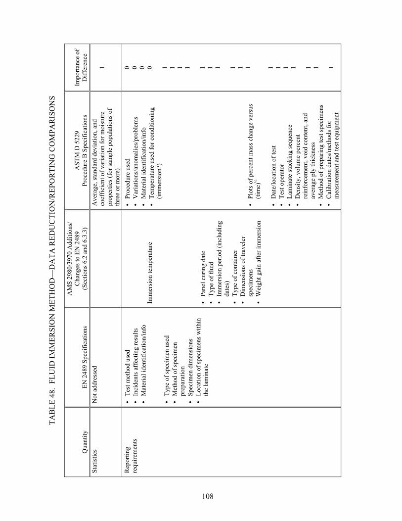
108
TA
BLE
48.
FLU
ID IM
MER
SIO
N M
ETH
OD
—D
ATA
RED
UC
TIO
N/R
EPO
RTI
NG
CO
MPA
RIS
ON
S
Qua
ntity
EN
248
9 Sp
ecifi
catio
ns
AM
S 29
80/3
970
Add
ition
s/
Cha
nges
to E
N 2
489
(Sec
tions
6.2
and
6.3
.3)
AST
M D
522
9 Pr
oced
ure
B S
peci
ficat
ions
Im
porta
nce
ofD
iffer
ence
St
atis
tics
Not
add
ress
ed
A
vera
ge, s
tand
ard
devi
atio
n, a
nd
coef
ficie
nt o
f var
iatio
n fo
r moi
stur
e pr
oper
ties (
for s
ampl
e po
pula
tions
of
thre
e or
mor
e)
1
Rep
ortin
g re
quire
men
ts
• • • • • • • • • • • • •
• • • • • • • • • • •
Test
met
hod
used
In
cide
nts a
ffec
ting
resu
lts
Mat
eria
l ide
ntifi
catio
n/in
fo
Ty
pe o
f spe
cim
en u
sed
Met
hod
of sp
ecim
en
prep
arat
ion
Spec
imen
dim
ensi
ons
Loca
tion
of sp
ecim
ens w
ithin
th
e la
min
ate
Imm
ersi
on te
mpe
ratu
re
Pa
nel c
urin
g da
te
Type
of f
luid
Im
mer
sion
per
iod
(incl
udin
g da
tes)
Ty
pe o
f con
tain
er
Dim
ensi
ons o
f tra
vele
r sp
ecim
ens
Wei
ght g
ain
afte
r im
mer
sion
Proc
edur
e us
ed
Var
iatio
ns/a
nom
alie
s/pr
oble
ms
Mat
eria
l ide
ntifi
catio
n/in
fo
Tem
pera
ture
use
d fo
r con
ditio
ning
(im
mer
sion
?)
Pl
ots o
f per
cent
mas
s cha
nge
vers
us
(tim
e)½
D
ate/
loca
tion
of te
st
Test
ope
rato
r La
min
ate
stac
king
sequ
ence
D
ensi
ty, v
olum
e pe
rcen
t re
info
rcem
ent,
void
con
tent
, and
av
erag
e pl
y th
ickn
ess
Met
hod
of p
repa
ring
test
spec
imen
s C
alib
ratio
n da
tes/
met
hods
for
mea
sure
men
t and
test
equ
ipm
ent
0 0 0 0 1 1 1 1 1 1 1 1 1 1 1 1 1 1 1 1 1

109
TA
BLE
48.
FLU
ID IM
MER
SIO
N M
ETH
OD
—D
ATA
RED
UC
TIO
N/R
EPO
RTI
NG
CO
MPA
RIS
ON
S (C
ontin
ued)
Qua
ntity
EN
248
9 Sp
ecifi
catio
ns
AM
S 29
80/3
970
Add
ition
s/
Cha
nges
to E
N 2
489
(Sec
tions
6.2
and
6.3
.3)
AST
M D
522
9 Pr
oced
ure
B S
peci
ficat
ions
Im
porta
nce
ofD
iffer
ence
R
epor
ting
requ
irem
ents
(c
ontin
ued)
• • • • • • • •
Res
ults
of p
reco
nditi
onin
g Sp
ecim
en d
imen
sion
s prio
r to
and
follo
win
g m
oist
ure
cond
ition
ing
Type
of c
ham
ber u
sed
Moi
stur
e le
vel u
sed
for c
ondi
tioni
ng
Mea
sure
men
t tim
e in
terv
al
Tem
pera
ture
and
rela
tive
hum
idity
of
the
test
ing
lab
Spec
imen
mas
s at e
ach
time
leve
l Eq
uilib
rium
moi
stur
e co
nten
t, in
pe
rcen
t
1 1 1 1 1 1 1

3. FOLLOW-ON TESTING.
Based on the comparative assessments of equivalence presented in section 2 and input received from the evaluators at the August meeting (section 2.1), 4 of the 16 types of tests were selected for follow-on testing to further assess test method equivalency. Note that the selection of these four tests for follow-on testing only reflects the need for additional test data to assess equivalency and is not a reflection of their degree of equivalency relative to other tests. The four types of tests selected for follow-on testing and the parameter(s) to be investigated are presented in the following sections. All testing will be performed using autoclave, prepreg carbon/epoxy composite materials. 3.1 LAMINA COMPRESSION TESTING: EFFECTS OF GAGE LENGTH.
The test method comparison for lamina compression testing presented in section 2.4 revealed a potentially significant difference in specimen gage lengths. Although similar gage lengths are listed for the prEN 2850-B and SACMA SRM 1 test methods (5 mm versus 4.75 mm, respectively), the AMS 2980 and 3970 specifications specify a 12.5-mm gage length. It is not well understood how this difference in gage length (4.75 mm versus 12.5 mm) will affect the delivered compression strengths produced in lamina compression testing. Thus, follow-on testing has been recommended to determine the effects of specimen gage length on delivered lamina compression strength. Testing is proposed using specimens with both 4.75-mm (~3/16-in.) and 12.5-mm (~1/2-in.) gage length specimens. Both unidirectional prepreg laminates and 0/90 prepreg fabric laminates will be tested. Testing will be conducted at room temperature/ambient as well as 82ºC (180ºF)/wet conditions. 3.2 LAMINATE COMPRESSION TESTING: EFFECTS OF LOADING METHOD.
The two test methods compared for laminate compression testing follow procedures generated for open-hole compression testing, but use a specimen without a hole. The test fixture specified in these two test methods, SACMA SRM 3 and ASTM D 6484, is very similar. As described in section 2.5, however, the method used to load the test fixture differs significantly and may produce differences in delivered compression strengths. Whereas ASTM D 6484 currently requires hydraulic wedge grips to be used to grip the test fixture, the SACMA SRM 3 test method allows the test fixture to be end-loaded between two parallel platens of the test machine. Thus, follow-on testing has been recommended to determine the effects of loading method on the delivered compression strength of composite laminates. Testing will be performed both with the test fixture gripped (hydraulic wedge grips) and with the test fixture end-loaded. Both multidirectional prepreg laminates and prepreg fabric laminates will be tested. Testing will be conducted at room temperature/ambient as well as 82ºC (180ºF)/wet conditions. 3.3 IN-PLANE SHEAR TESTING: EFFECTS OF SPECIMEN THICKNESS.
As described in section 2.8, the two test methods compared for in-plane shear testing both use +45° type laminates loaded in tension. Although both the prEN 6031 test method and the AMS 2980 and 3970 specifications require an 8-ply +45° laminate for either unidirectional tape or woven fabric, ASTM D 3518 requires 16-, 20-, or 24-ply unidirectional tape laminates or 8-, 12-, or 16-ply woven fabric laminates. As discussed in section 2.8, a specimen thickness effect on
110

strength has been reported [7], resulting in lower delivered shear strengths from thinner +45° specimens. To further investigate the effects of specimen thickness, follow-on testing has been recommended using multiple thickness specimens fabricated from both prepreg tape and prepreg fabric materials. Testing will be conducted at room temperature/ambient as well as 82ºC (180ºF)/wet conditions. 3.4 CONSTITUENT CONTENT DETERMINATION: EFFECTS OF SPECIMEN SIZE AND WEIGHING ACCURACY.
Both of the test methods described in section 2.14, EN 2564 Method A and ASTM D 3171 Method I procedure B, use an acid digestion procedure to determine the constituent content of composite laminates. Two significant differences between the test methods will be investigated in follow-on testing. First, the effect of differences in the required specimen size reported between the two test methods will be investigated. Whereas EN 2564 requires a 200 mm2 rectangular specimen 2 mm thick, ASTM D 3171 requires a minimum surface area of 625 mm2 and specifies a minimum mass requirement. Second, the difference in the required weighing accuracy between the two test methods will be investigated. Although ASTM D 3171 requires that weights be determined to the nearest 0.1 mg, EN 2564 only requires accuracy to the nearest ±1 mg. Follow-on testing will be used to investigate the significance of both of these differences on the constituent content determinations. Both unidirectional prepreg laminates and prepreg fabric laminates will be used in these determinations. 4. CONCLUSIONS.
The detailed test method comparison between ASTM and primarily EN test specifications was performed for 16 tests. Nine test methods appear to be equivalent. Of the remaining seven test methods four were chosen for further comparison by performing the tests to determine whether the differences in test methods are significant. These were lumina and laminate compression testing, in-plane shear testing, and constituent content determination. Three tests, compression after impact (CAI) and Mode I and Mode II fracture properties tests were deemed sufficiently different so that no reasonable correlation will be obtained from additional testing. The CAI test methods serve different purposes—this is explained in the test summary. The Mode II tests are very different—one is a three point bend and the other is a four point bend. Additionally, the ASTM test method used is only a draft standard. The differences between the prEN and ASTM test methods for Mode I are not quite so obvious, but there are nonetheless significant differences: length and thickness of the insert and the definition of G (area under curve over a 100-mm length of propagation versus an R-curve containing several G measurements). The general conclusion from this study is that except for fracture properties, the CEN test methods will provide test results similar to the ASTM test methods for at least nine test methods with an additional four test methods having a very good chance to meet equivalency through follow-on testing. The current research has also provided a blueprint on how to conduct a test equivalency study to permit data inclusion into MIL-Handbook-17 from nonstandard tests.
111

5. REFERENCES.
1. Carbon Composite Wet Repair Qualification Program Report to the Commercial Aircraft Composite Repair Committee: Tenax HTA 5131 200tex f3000/Epocast 52 A/B, Report No. 2192-JRL-140901/Q077-1, Tenax Fibers GmbH, Wuppertal, Germany, May, 2002.
2. CACRC SAE AMS 2970, “Technical Specification: Carbon Fiber Fabric and Epoxy
Resin Wet Lay-up Repair Material,” November 1996. 3. MIL Handbook-17 Revision F, Composite Materials Handbook. 4. “ASTM/MIL-HDBK-17/SACMA Review of Selected AECMA Test Methods,” October
10, 1995, Rich Fields, Editor (email). 5. SAE AMS 3970, “Technical Specification: Fiber Fabric Repair Prepreg, 125°C (250°F)
Vacuum Curing, December 1999. 6. Fields, R.E., “Survey of the Test Methods Within SAE AMS 3970,” to be published. 7. Kellas, S., Morton, J., and Jackson, K.E., “Damage and Failure Mechanisms in Scaled
Angled-Ply Laminates: Fourth Composites Symposium on Fatigue and Fracture, ASTM STP 1156, American Society for Testing and Methods, 1993, pp. 257-280.
112