Fuzzy logic in control systems: fuzzy logic controller. II ...
1 | © I J A I T I 2 0 1 2 VOLUME 1 NUMBER 2 (Mar/Apr 2012) ISSN: 2277–1891
Original Research Articles
A Comparison between the Performance of Fuzzy Logic-
based PD Controller and General PD Controller
Abstract:
A comparative study on performance in terms of transient time response
specifications for position control of a separately excited DC Servomotor using
Fuzzy logic control on PD strategy and general PD control strategy is done.
Fuzzy Logic Controller (FLC) based on PD strategy is designed for both the
inference mechanisms- Mamdani type and Takagi-Sugeno type. Robustness test
for both the controllers-FLC and general PD controller has shown that Fuzzy
Logic Controller is more robust as compared to general PD controller. All the
work, experiments and simulation are done in MATLAB software.
Keywords: Fuzzy logic controller, PD controller, DC servomotor, position
control system, time response.
Introduction:
The objective of this paper is to represent the comparative study of
performance in terms of time response specifications of a PD-type FLC and a
general PD controller. It has been seen that there are various advantages of the
fuzzy logic controller over the general PD controller. Designing the Fuzzy Logic
Controller *2+ doesn’t require previous knowledge on system characteristic
equation as PD controller. Fuzzy Logic Controllers, so called intelligent control
function, represents much closely human thinking and natural language than
logical control system used by PD control. The implementation of fuzzy logic
control shows its robustness as the results in case of both simulation and
experiment remain identical with respect to the load mass change [3].
This paper presents the performance of two types of fuzzy logic-based
controllers- Takagi Sugeno based and Mamdani based. The main difference
between Mamdani and Takagi-Sugeno is that the Sugeno output membership
functions are either linear or constant. Also the difference lies in the
consequents of their fuzzy rules, and thus their aggregation and defuzzification
procedures differ suitably [10]. The number of the input fuzzy sets and fuzzy
rules needed by the Sugeno fuzzy system depend on the number and extrema
of the function to be approximated. In Takagi-Sugeno method a large number
of fuzzy rules must be employed to approximate periodic or highly oscillatory
functions. The minimal configuration of the Takagi-Sugeno fuzzy systems can be
reduced and becomes smaller than that of the Mamdani systems if non
trapezoidal and non-triangular fuzzy sets are used. Takagi-Sugeno controllers
Researchers
Sankhadip Saha, Mrityunjay
Kumar Ray, Priyanka Roy
Department of Electrical
Engineering
Netaji Subhash Engineering College
Kolkata, India
Email-

2 | © I J A I T I 2 0 1 2 VOLUME 1 NUMBER 2 (Mar/Apr 2012) ISSN: 2277–1891
usually have far more adjustable parameters in the rule consequent and the number of the parameters grows
exponentially with the number of input variables. Mamdani is easy to form compared to Takagi- Sugeno
method [11].
Modelling of The Plant
To derive the performance of all the controllers, the plant is chosen as DC servomotor. The controller objective
is to control the position of a mechanical load driven by the DC servomotor. Direct current machines are
widely used in closed loop control systems, particularly for the control of speed and torque [4]. DC servomotor
is chosen since it is easier to control where keeping the field current as constant and changing the armature
voltage or current can vary the position or the speed of the DC servomotor. Figure1 below shows the
schematic of the armature controlled DC servomotor with a fixed field circuit. For transfer function derivation,
this system was divided into three major components of equation, which are electrical equation, mechanical
equation, and electro-mechanical equation.
Fig.1 Schematic of DC servomotor system
The electrical equation for DC servomotor system could simply be obtained based on the Kirchhoff’s Voltage
Law as follows:
dt
diLtiRtete a
aaaba )()()( (1)
taking Laplace transform of the above
)()()()( sIsLRsEsE aaba (2)
where ae and ai are the armature voltage and current respectively, aR is the armature resistance, and aL is
the armature inductance. The back-emf be , on the other hand, induced by the angular speed of the motor
shaft, such that
)()()( ssksksE mbmbb (3)
Where bk the back-emf is constant, m is the angular speed, and m is the angular displacement.
Contrary to electrical equation, the mechanical equation can be obtained as follows:
dt
dB
dt
dJt mm
m
2
2
)( (4)
Taking Laplace transform of the above
3 | © I J A I T I 2 0 1 2 VOLUME 1 NUMBER 2 (Mar/Apr 2012) ISSN: 2277–1891
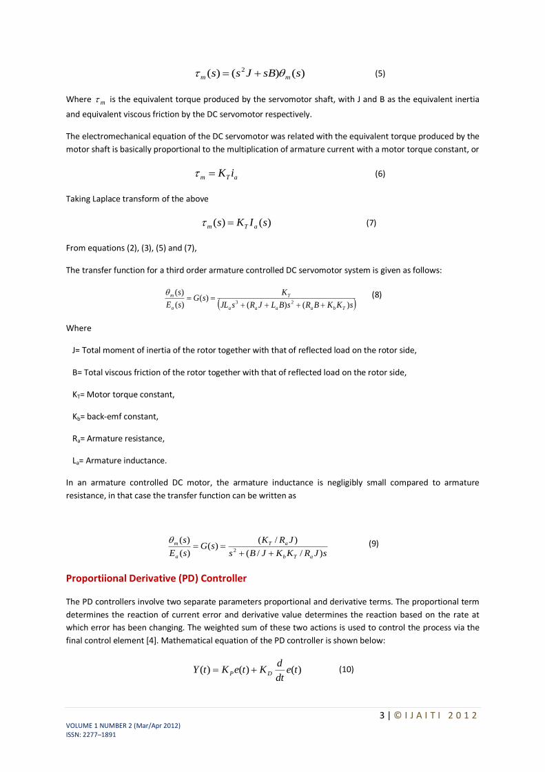
)()()( 2 ssBJss mm (5)
Where m is the equivalent torque produced by the servomotor shaft, with J and B as the equivalent inertia
and equivalent viscous friction by the DC servomotor respectively.
The electromechanical equation of the DC servomotor was related with the equivalent torque produced by the
motor shaft is basically proportional to the multiplication of armature current with a motor torque constant, or
aTm iK (6)
Taking Laplace transform of the above
)()( sIKs aTm (7)
From equations (2), (3), (5) and (7),
The transfer function for a third order armature controlled DC servomotor system is given as follows:
sKKBRsBLJRsJL
KsG
sE
s
Tbaaaa
T
a
m
)()()(
)(
)(23
(8)
Where
J= Total moment of inertia of the rotor together with that of reflected load on the rotor side,
B= Total viscous friction of the rotor together with that of reflected load on the rotor side,
KT= Motor torque constant,
Kb= back-emf constant,
Ra= Armature resistance,
La= Armature inductance.
In an armature controlled DC motor, the armature inductance is negligibly small compared to armature
resistance, in that case the transfer function can be written as
sJRKKJBs
JRKsG
sE
s
aTb
aT
a
m
)//(
)/()(
)(
)(2
(9)
Proportiional Derivative (PD) Controller
The PD controllers involve two separate parameters proportional and derivative terms. The proportional term
determines the reaction of current error and derivative value determines the reaction based on the rate at
which error has been changing. The weighted sum of these two actions is used to control the process via the
final control element [4]. Mathematical equation of the PD controller is shown below:
)()()( tedt
dKteKtY DP (10)

4 | © I J A I T I 2 0 1 2 VOLUME 1 NUMBER 2 (Mar/Apr 2012) ISSN: 2277–1891
Design of fuzzy logic controller
The fuzzy logic based controller (or Fuzzy Controller) was first implemented by Mamdani and Assilian [7] based
on the fuzzy logic system generalized from fuzzy set theory introduced by Zadeh [8]. In contrast to
conventional control techniques, fuzzy logic control is best utilized in complex ill-defined processes that can be
controlled by a skilled human operator e.g. complex chemical plant without much knowledge of their
underlying dynamics [9]. Generally, Fuzzy Logic Controller comprises of four principal components [2], [5], [10]:
fuzzification
the rule base
the inference engine
defuzzification
The components of the Fuzzy Logic Controller can be clearly seen based in Figure 2 below:
Fig.2 Fuzzy Logic Controller(FLC)
To design the fuzzy logic controller, crisp input and output are chosen suitably. Though several observations the input and output fuzzy variables has been identified in Table 1 below:
No Input Output
1 Error voltage between the actual and desired angular position. (e)
Control action to the system plant
(u) 2 The change of error voltage
between the actual and desired angular position. (edot)
Table 1: Input and output of fuzzy variables
Here error and rate of change of error i.e. derivative of error are chosen as crisp inputs. Integral control action is not considered for selecting the crisp input of the fuzzy logic controller because of the fact that from the closed loop response it is found that improvement steady state specification is not much necessary.
A PD-type fuzzy logic controller utilizing angular position error and derivative of angular position error is developed to control the DC servomotor system [1]. If we define the error as y
spyke )( , a linguistic value of
positive small for the error means that the process output is below the set point but near to it so that the
magnitude )(kysp
y is small. Similarly linguistic value of negative big for the linguistic variable error means that
the output is above the set point and the magnitude of )(ky
spy
is such that it is far away from the set point. A

5 | © I J A I T I 2 0 1 2 VOLUME 1 NUMBER 2 (Mar/Apr 2012) ISSN: 2277–1891
linguistic value of zero means that the process output is at the set point. Since )()1()1()()( kykykekeke ,
negative )(ke means that the process output has increased when compared with its immediate past value.
The term sets (number of membership functions to cover the respective normalized domains) for inputs, )(ke
and )(ke are N(negative), Z(zero) and P(positive).The term sets of the membership functions of the output, )(ku are chosen as {NB, N, ZE, P, PB} which are abbreviations for Negative big, Negative small, Zero, Positive
small and Positive big respectively.
For a PD like fuzzy controller, the rule base for both the inference mechanisms-Takagi-Sugeno type and Mamdani type FLC is same and presented in a tabular form known as Fuzzy Associative Memory (FAM) table.
edot
e
P Z N
P PB P ZE
Z P ZE N
N ZE N NB
Table 2 : FAM table for both Takagi-Sugeno and Mamdani type FLC
It has been seen that 9 rules are needed to compute the rules for three membership functions of error and rate of change of error.
The membership functions and the term sets of the membership functions for both the inputs- error and rate of change of error are same for Takagi-Sugeno type FLC and Mamdani type FLC and are shown in figure 3 and 4.
The frame of error is e, L e , X , μe
Where L e is the set of linguistic values that error can take. We may use the following fuzzy subsets to describe the linguistic values for error:
NegativeEror (N), ZeroError (Z), PositiveEror (P)
i.e. L e = {N, Z, P}
The frame of the rate of change of error (derivative of error) is
edot, L edot, Y , μedot
The following fuzzy subsets are used for the rate of change of error:
NegativeError (N), ZeroError (Z), PositiveError (P)
i.e L edot = { N, Z, P }
Fig.3 Membership functions for error (e)
Fig.4 Membership functions for rate of change of error (edot)

6 | © I J A I T I 2 0 1 2 VOLUME 1 NUMBER 2 (Mar/Apr 2012) ISSN: 2277–1891
It is to be noted that in the Takagi-Sugeno type inference mechanism [10],[20] the crisp output function u is given by, u = k f (x1,x2), where the function f (x1,x2) is a nonlinear function. For simplicity it is approximated by a linear function of the form f (x1,x2) = k0 + k1 x1 + k2 x2 where k0, k1, k2 are linear parameters. The parameters of the membership functions in the output are shown in the following table:
Sl.no.
Membership functions
Parameters
[ k2 k1 k0]
1 NB [0.5 1 -1]
2 N [0.5 1 -0.5]
3 ZE [0.5 1 0]
4 P [0.5 1 0.5]
5 PB [0.5 1 1]
Table 3 : Parameters of the membership functions for the output of Takagi-Sugeno type FLC
It is noted that the DC term 0k
in the membership function, ZE is set to 0, since no D.C. voltage is required to be applied to the armature of the servomotor when the error in position and rate of change of position are
approaching zero value. Also, the sign of constant terms 0k
for the output membership functions; it is negative
for NB and N and positive for P and PB. Besides, the strengths of the co-efficients 1k
and 2k
in the parameters are symmetric in NB and PB, N and P. The numerical values of these co-efficients are chosen as a first trial and are tuned during simulation to improve the system performance.
The membership functions for the output for Mamdani type FLC is shown in figure
The frame of Output is
op, L op , X , μop
Where L op is the set of linguistic values that output can take. We may use the following fuzzy subsets to describe the linguistic values for output:
Negative Big (NB), Negative Small (N), ZeroError (ZE), Positive Small (P), Positive Big (PB)
i.e L op = { NB, N, ZE, P, PB }
Fig.5 Membership functions for Output for Mamdani-type FLC
The control surface for both types of controllers-Takagi Sugeno type and Mamdani type are shown in figure 6 and 7 respectively.
Fig.6 Control Surface for Takagi-Sugeno type FLC

7 | © I J A I T I 2 0 1 2 VOLUME 1 NUMBER 2 (Mar/Apr 2012) ISSN: 2277–1891
Fig.7 Control Surface for Mamdani type FLC
Analysis And Results
A comparative study of the transient performance between the General PD Controller and both FLC (Takagi-Sugeno and Mamdani) is simulated in MATLAB software. The robustness test of the General PD Controller and both FLC (Sugeno and Mamdani) is performed by changing the load i.e. the moment of inertia is multiplied by the factors of 0.5 and 2. The defuzzification method used for Takagi Sugeno based FLC and Mamdani based FLC are weighted sum method and centroid method respectively
System parameters:
The following parameters are considered for the position control system using DC Servo motor:
J = 5.4 × 10⁻⁴ kg-m2 / sec2
B = 6.3 × 10⁻³ Nm/sec KT= 0.089 Nm/A Kb= 0.1 V/rad/sec Ra= 5 ohm La= 0.0001 ≈ negligible
So from equation (9), the transfer function for D.C servomotor becomes
sssG
sE
s
a
m
96.14
)96.34()(
)(
)(2
A. Time Response of Servomotor Transfer Function for General PD Controller and both FLCs (Takagi-Sugeno and Mamdani type)
Fig.8 MATLAB code of G(s) = )96.14
2/(96.32 ss
for General PD Controller for position control system
8 | © I J A I T I 2 0 1 2 VOLUME 1 NUMBER 2 (Mar/Apr 2012) ISSN: 2277–1891
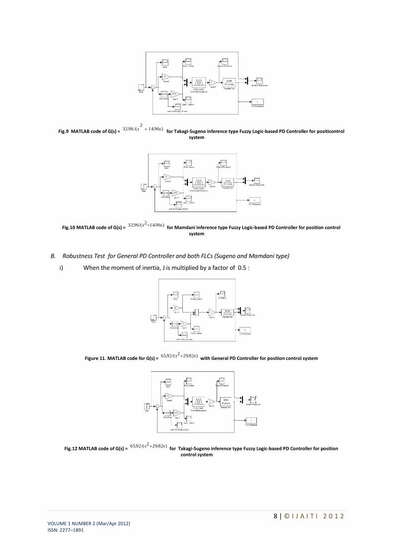
Fig.9 MATLAB code of G(s) = )96.14
2/(96.32 ss
for Takagi-Sugeno inference type Fuzzy Logic-based PD Controller for positicontrol system
Fig.10 MATLAB code of G(s) = )96.142/(96.32 ss
for Mamdani inference type Fuzzy Logic-based PD Controller for position control system
B. Robustness Test for General PD Controller and both FLCs (Sugeno and Mamdani type)
i) When the moment of inertia, J is multiplied by a factor of 0.5 :
Figure 11. MATLAB code for G(s) = )82.292/(92.65 ss
with General PD Controller for position control system
Fig.12 MATLAB code of G(s) = )82.292/(92.65 ss
for Takagi-Sugeno inference type Fuzzy Logic-based PD Controller for position control system

9 | © I J A I T I 2 0 1 2 VOLUME 1 NUMBER 2 (Mar/Apr 2012) ISSN: 2277–1891
Fig.13 MATLAB code of G(s) = )82.292/(92.65 ss for Mamdani inference type Fuzzy Logic-based PD Controller for position control system
ii) When the moment of inertia, J is multiplied by a factor of 2:
Fig.14 MATLAB code for G(s) = )48.72/(48.16 ss
with General PD Controller for position control system
Fig.15 MATLAB code of G(s) = )48.72/(48.16 ss
for Takagi-Sugeno inference type Fuzzy Logic-based PD Controller for position control system
Fig.16 MATLAB code of G(s) = )48.72/(48.16 ss
for Mamdani inference type Fuzzy Logic-based PD Controller for position control system
The Comparative performance assessment of both the controllers- General PD type and FLC (Takagi-Sugeno and Mamdani type) is summarised in Table 4:

10 | © I J A I T I 2 0 1 2 VOLUME 1 NUMBER 2 (Mar/Apr 2012) ISSN: 2277–1891
Moment of inertia(J)
Controller Overshoot (%) Rise time(s) Settling time(s)
J = 5.4 × 10⁻⁴ kg-m2 / sec2
General PD Controller
11.85
0.1301
0.62
PD-type FLC (Sugeno)
0
0.47
0.47
PD-type FLC (Mamdani)
0
0.28
0.28
J =0.5 ×(5.4 × 10-4 )kg-m
2 / sec
2
General PD Controller
1.2
0.15
0.29
PD-type FLC (Sugeno)
0
0.52
0.52
PD-type FLC (Mamdani)
0
0.29
0.29
J = 2 ×(5.4 × 10-4 )kg-m2 / sec2
General PD Controller
26
0.151
1.24
PD-type FLC (Sugeno)
0
0.35
0.35
PD-type FLC (Mamdani)
0
0.21
0.21
Table 4: Time response comparison for General PD Controller and PD-type FLC (Takagi-Sugeno and Mamdani type)
Conclusion and Future Works
The Fuzzy logic controllers (Sugeno type and Mamdani type both) have shown good time responses for the servomotor as compared to general PD controller. The design for the Fuzzy logic inference system and ranges of membership functions have succeeded in getting critically damped like response for the servomotor. The fuzzy logic controllers (Takago-Sugeno and Mamdani type) are found to be more robust as compared to general PD controller. This is verified by considering the fuzzy logic controller tuned for one plant to a modified plant. As the servomotor is used for position control system like in robotic arm, it is used to pick some objects of varying masses. The fuzzy logic ontroller has been designed and tuned for an expected average mass of the object to meet prescribed overshoot imposition and settling time in transient response. Since the performance should not degrade too much even if the masses change over wide ranges. We simulate the situation by multiplying the moment of inertia J by a factor of 0.5 and 2. It has been seen that for both the fuzzy logic controllers, Takagi-Sugeno and Mamdani type, the overshoot is 0% and settling time is less than 1 second which is obtained when the parameter J is multiplied by a factor of 0.5 and 2. But the general PD controller shows considerable overshoot when the moment of inertia is multiplied by a factor of 0.5 and 2. Simulations are performed in MATLAB/SIMULINK environment.
This work can be tested with ANFIS (Adaptive Neuro Fuzzy Inference System) to optimize the performance while genetic algorithm can be used to tune the scaling gains of the fuzzy logic controller to get better time response in nonlinear application. Our future work will focus on designing fuzzy logic controller to get satisfactory time response to meet the hardware specifications of the servomotor.
Acknowledgment
The authors acknowledge the support from the ‘Control and Automation Centre (CAC)’ of Netaji Subhash Engineering College, Kolkata, India.

11 | © I J A I T I 2 0 1 2 VOLUME 1 NUMBER 2 (Mar/Apr 2012) ISSN: 2277–1891
References
[1] Sankhadip Saha, Performance Comparison of PID-based Position Control System with FLC-based Position Control System with FLC-based Position Control System, TIG Research Journal, Vol. 1, No. 2, Sept. 2008.
[2] Lee, C.C., Fuzzy Logic in Control System : Fuzzy Logic Controller – Part I and Part II, IEEE Transactions on SMC, 20, pp. 404-435, 1990.
[3] Hoang Le-Huy and Maher Hamdi, Control of Direct Drive DC Motor by Fuzzy Logic, IEEE Transactions, pp. 732-738, 1993.
[4] N.S.Nise, Control System Engineering, John Wiley & Sons, 4th Edition, pp. 764-767, 2004.
[5] Mamdani, E.H., Efstathiou, H.J., and Sugiyama, K., Developments in Fuzzy Logic Controller, Proc. of the 23rd IEEE Conference on Decision and Control, pp. 888-893, 1984.
[6] Mamdani, E.H., Application of Fuzzy Algorithm for Simple Dynamic Plant, Proc. IEE 121, 12, pp. 1585-1588, 1974.
[7] Mamdani, E.H. and S. Assilian, An Experiment with Linguistic Synthesis of a Fuzzy Logic Controller, Int. J. Man Mach Studies, 7, 1, pp. 1-13, 1975.
[8] Zadeh, L.A., The Concept of a Linguistic Variable and Its Application to Approximate Reasoning I, II, III, Information Sciences 8,pp. 199-251, pp. 301-357; 9 pp. 45-80
[9] T. Ross. “Fuzzy Logic in Engineering Applications”. McGraw-Hill, New York, 1995
[10] D. Driankov, H. Hellendoorn, and M. Reinfrank.” An Introduction to Fuzzy Control”. Springer-Verlag, New York, 1993.
[11] Rakesh K. Arya, Approximations of Mamdani Type Multi-Fuzzy Sets Fuzzy Controller by Simplest-Fuzzy Controller, International Journal of Computational Cognition, Vol. 4, No. 2, June 2006.
[12] Jamal-abd-altayef and Zhu Qun-xiong, Real-Time DC Motor Position Control by (FPID) Controllers and design (FLC) using LabVIEW software simulation, International Journal of Engineering Studies, ISSN 0975- 6469, Vol. 1, No. 4, pp. 247-256, 2009.
[13] S.R. Khuntia, K.B. Mohanty, S. Panda and C. Ardil, A Comparative Study of P-I, I-P, Fuzzy and Neuro-Fuzzy Controllers for Speed Control of DC Motor Drive, International Journal of Electrical Systems Science and Engineering 1:1 2009.
[14] N. A. Muhamad, and S.A.M. Ali, LabVIEW with Fuzzy Logic Controller Simulation Panel for Condition Monitoring of Oil and Dry Type Transformer, World Academy of Science, Engineering and Technology 2006.
[15] Vineet Kumar, K.P.S. Rana and Vandana Gupta, Real-Time Performance Evaluation of a Fuzzy PI + Fuzzy PD Controller for Liquid-Level Process, International Journal of Intelligent Control and Systems, Vol. 13, No. 2, pp. 89-96, June 2008.
[16] Sahin, T. Eroglu, E. Zergeroglu, E., An adaptive output feedback tracking control of robot manipulator via fuzzy logic based compensation, Advanced Motion Control, 2006. 9th IEEE International Workshop, pp. 681 – 686.
[17] Kulkarni, A.S., El-Sharkawi, M.A., Intelligent precision position control of elastic drive systems, Energy Conversion, IEEE Transactions, Vol. 16 , Issue:1, pp. 26 – 31, March 2001.
[18] Wahyunggoro, O., Saad, N.B., Development of fuzzy-logic-based self tuning PI controller for servomotor, Control, Automation, Robotics and Vision, 2008. ICARCV 2008. 10th International Conference, pp. 1545 – 1550, 17-20 Dec. 2008.
[19] Jong-Hwan Kim Kwang-Choon Kim Chong, E.K.P., Fuzzy precompensated PID controllers, Control Systems Technology, IEEE Transactions, Vol. 2 , Issue:4, pp. 406 – 411, Dec. 1994.
[20] T. Takagi, and M. Sugeno, “Fuzzy identification of systems and its applications to modeling and control,” IEEE trans. on systems, man, and cybernetics, vol. 15, no 1, pp. 116-132, 1985
Fig.17 Step response of G(s)= 96.32 /(
ss 96.142 ) for General PD Controller
Fig.18 Step response of G(s)= 96.32 /(
ss 96.142 ) for Takagi-Sugeno
inference type Fuzzy Logic based PD Controller for position control system
Fig.19 Step response of G(s)= /( ) Mamdani inference type Fuzzy Logic- based PD Controller for position control system

12 | © I J A I T I 2 0 1 2 VOLUME 1 NUMBER 2 (Mar/Apr 2012) ISSN: 2277–1891
Fig.20 Step response of G(s) =
)82.292/(92.65 ss for General PD
Controller for position control
system.
Fig.21 Step response of G(s) =
)82.292/(92.65 ss for Takagi Sugeno
inference type Fuzzy Logic-base PD
Controller for position control
system.
Fig.22 Step response of G(s)=
)82.292/(92.65 ss for Mamdani
inference type Fuzzy Logic-based PD
Controller for position control system
Fig.23 Step response of G(s) =
)48.72/(48.16 ss for General PD
Controller for position control system
Fig.24. Step response of G(s) =
)48.72/(48.16 ss for Takagi Sugeno
inference type Fuzzy Logic-based PD
Controller for position control system
Fig.25. Step response of G(s) =
)48.72/(48.16 ss for Mamdani
inference type Fuzzy Logic-based PD
Controller for position control system
Author Details:
Sankhadip Saha is currently employed at Department of Electrical Engineering, Netaji Subhash Engineering College, Kolkata, India; as Assistant Professor. He is also a professional member of Institution of Engineering and Technology (IET), United Kingdom. His main research interests are application of computer intelligence using various soft computing and statistical techniques.
Mrityunjay Kumar Ray is currently pursuing Bachelor of Technology (B-Tech) degree in “Electrical Engineering” from Netaji Subhash Engineering College, Technocity, Garia under West Bengal University of Technology, Kolkata, India. His current research field includes image processing, pattern recognition, signal processing, embedded system design, control system, artificial intelligence, optimization techniques and biomedical signal analysis.
Priyanka Roy is currently working in
the Department of Electrical
Engineering in Netaji Subhas
Engineering College as Assistant
Professor. She is involved in research
and development in the field of signal
processing, power electronics and
virtual instrumentation.