A Comparison Between Pump & Treat Technique and Permeable … · 2018-05-28 · derives from the...
10
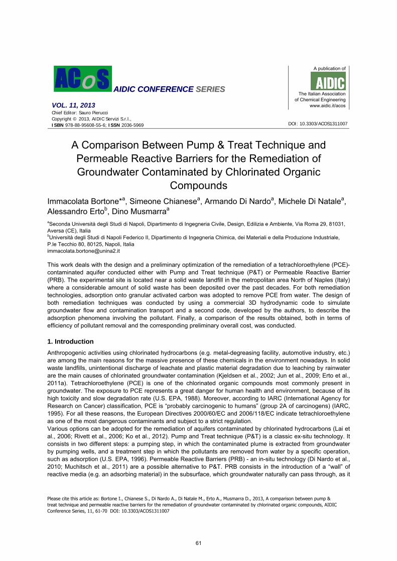
AIDIC CONFERENCE SERIES VOL. 11, 2013 A publication of The Italian Association of Chemical Engineering www.aidic.it/acos Chief Editor: Sauro Pierucci Copyright © 2013, AIDIC Servizi S.r.l., ISBN 978-88-95608-55-6; ISSN 2036-5969 A Comparison Between Pump & Treat Technique and Permeable Reactive Barriers for the Remediation of Groundwater Contaminated by Chlorinated Organic Compounds Immacolata Bortone* a , Simeone Chianese a , Armando Di Nardo a , Michele Di Natale a , Alessandro Erto b , Dino Musmarra a a Seconda Università degli Studi di Napoli, Dipartimento di Ingegneria Civile, Design, Edilizia e Ambiente, Via Roma 29, 81031, Aversa (CE), Italia b Università degli Studi di Napoli Federico II, Dipartimento di Ingegneria Chimica, dei Materiali e della Produzione Industriale, P.le Tecchio 80, 80125, Napoli, Italia [email protected] This work deals with the design and a preliminary optimization of the remediation of a tetrachloroethylene (PCE)- contaminated aquifer conducted either with Pump and Treat technique (P&T) or Permeable Reactive Barrier (PRB). The experimental site is located near a solid waste landfill in the metropolitan area North of Naples (Italy) where a considerable amount of solid waste has been deposited over the past decades. For both remediation technologies, adsorption onto granular activated carbon was adopted to remove PCE from water. The design of both remediation techniques was conducted by using a commercial 3D hydrodynamic code to simulate groundwater flow and contamination transport and a second code, developed by the authors, to describe the adsorption phenomena involving the pollutant. Finally, a comparison of the results obtained, both in terms of efficiency of pollutant removal and the corresponding preliminary overall cost, was conducted. 1. Introduction Anthropogenic activities using chlorinated hydrocarbons (e.g. metal-degreasing facility, automotive industry, etc.) are among the main reasons for the massive presence of these chemicals in the environment nowadays. In solid waste landfills, unintentional discharge of leachate and plastic material degradation due to leaching by rainwater are the main causes of chlorinated groundwater contamination (Kjeldsen et al., 2002; Jun et al., 2009; Erto et al., 2011a). Tetrachloroethylene (PCE) is one of the chlorinated organic compounds most commonly present in groundwater. The exposure to PCE represents a great danger for human health and environment, because of its high toxicity and slow degradation rate (U.S. EPA, 1988). Moreover, according to IARC (International Agency for Research on Cancer) classification, PCE is “probably carcinogenic to humans” (group 2A of carcinogens) (IARC, 1995). For all these reasons, the European Directives 2000/60/EC and 2006/118/EC indicate tetrachloroethylene as one of the most dangerous contaminants and subject to a strict regulation. Various options can be adopted for the remediation of aquifers contaminated by chlorinated hydrocarbons (Lai et al., 2006; Rivett et al., 2006; Ko et al., 2012). Pump and Treat technique (P&T) is a classic ex-situ technology. It consists in two different steps: a pumping step, in which the contaminated plume is extracted from groundwater by pumping wells, and a treatment step in which the pollutants are removed from water by a specific operation, such as adsorption (U.S. EPA, 1996). Permeable Reactive Barriers (PRB) - an in-situ technology (Di Nardo et al., 2010; Muchitsch et al., 2011) are a possible alternative to P&T. PRB consists in the introduction of a “wall” of reactive media (e.g. an adsorbing material) in the subsurface, which groundwater naturally can pass through, as it DOI: 10.3303/ACOS1311007 Please cite this article as: Bortone I., Chianese S., Di Nardo A., Di Natale M., Erto A., Musmarra D., 2013, A comparison between pump & treat technique and permeable reactive barriers for the remediation of groundwater contaminated by chlorinated organic compounds, AIDIC Conference Series, 11, 61-70 DOI: 10.3303/ACOS1311007 61
Transcript of A Comparison Between Pump & Treat Technique and Permeable … · 2018-05-28 · derives from the...
AAIIDDIICC CCOONNFFEERREENNCCEE SSEERRIIEESS VOL. 11, 2013
A publication of
The Italian Association
of Chemical Engineering www.aidic.it/acos
Chief Editor: Sauro Pierucci Copyright © 2013, AIDIC Servizi S.r.l., ISBN 978-88-95608-55-6; ISSN 2036-5969
A Comparison Between Pump & Treat Technique and Permeable Reactive Barriers for the Remediation of Groundwater Contaminated by Chlorinated Organic
Compounds
Immacolata Bortone*a, Simeone Chianesea, Armando Di Nardoa, Michele Di Natalea, Alessandro Ertob, Dino Musmarraa aSeconda Università degli Studi di Napoli, Dipartimento di Ingegneria Civile, Design, Edilizia e Ambiente, Via Roma 29, 81031, Aversa (CE), Italia bUniversità degli Studi di Napoli Federico II, Dipartimento di Ingegneria Chimica, dei Materiali e della Produzione Industriale, P.le Tecchio 80, 80125, Napoli, Italia [email protected]
This work deals with the design and a preliminary optimization of the remediation of a tetrachloroethylene (PCE)-contaminated aquifer conducted either with Pump and Treat technique (P&T) or Permeable Reactive Barrier (PRB). The experimental site is located near a solid waste landfill in the metropolitan area North of Naples (Italy) where a considerable amount of solid waste has been deposited over the past decades. For both remediation technologies, adsorption onto granular activated carbon was adopted to remove PCE from water. The design of both remediation techniques was conducted by using a commercial 3D hydrodynamic code to simulate groundwater flow and contamination transport and a second code, developed by the authors, to describe the adsorption phenomena involving the pollutant. Finally, a comparison of the results obtained, both in terms of efficiency of pollutant removal and the corresponding preliminary overall cost, was conducted.
1. Introduction
Anthropogenic activities using chlorinated hydrocarbons (e.g. metal-degreasing facility, automotive industry, etc.) are among the main reasons for the massive presence of these chemicals in the environment nowadays. In solid waste landfills, unintentional discharge of leachate and plastic material degradation due to leaching by rainwater are the main causes of chlorinated groundwater contamination (Kjeldsen et al., 2002; Jun et al., 2009; Erto et al., 2011a). Tetrachloroethylene (PCE) is one of the chlorinated organic compounds most commonly present in groundwater. The exposure to PCE represents a great danger for human health and environment, because of its high toxicity and slow degradation rate (U.S. EPA, 1988). Moreover, according to IARC (International Agency for Research on Cancer) classification, PCE is “probably carcinogenic to humans” (group 2A of carcinogens) (IARC, 1995). For all these reasons, the European Directives 2000/60/EC and 2006/118/EC indicate tetrachloroethylene as one of the most dangerous contaminants and subject to a strict regulation. Various options can be adopted for the remediation of aquifers contaminated by chlorinated hydrocarbons (Lai et al., 2006; Rivett et al., 2006; Ko et al., 2012). Pump and Treat technique (P&T) is a classic ex-situ technology. It consists in two different steps: a pumping step, in which the contaminated plume is extracted from groundwater by pumping wells, and a treatment step in which the pollutants are removed from water by a specific operation, such as adsorption (U.S. EPA, 1996). Permeable Reactive Barriers (PRB) - an in-situ technology (Di Nardo et al., 2010; Muchitsch et al., 2011) are a possible alternative to P&T. PRB consists in the introduction of a “wall” of reactive media (e.g. an adsorbing material) in the subsurface, which groundwater naturally can pass through, as it
DOI: 10.3303/ACOS1311007
Please cite this article as: Bortone I., Chianese S., Di Nardo A., Di Natale M., Erto A., Musmarra D., 2013, A comparison between pump & treat technique and permeable reactive barriers for the remediation of groundwater contaminated by chlorinated organic compounds, AIDIC Conference Series, 11, 61-70 DOI: 10.3303/ACOS1311007
61

is more permeable than the surrounding media while the adsorbing material captures the pollutants (Fiore and Zanetti, 2006; Di Natale et al., 2008). For both remediation technologies, adsorption onto granular activated carbon can be efficiently adopted to remove chlorinated compounds from water, combining high performances with an essential process system (Suzuki, 1990; Bembnowska et al., 2003; Pelech et al., 2003; Plagentz et al., 2006; Erto et al., 2012). Several sorbents can be used for organic compound removal, including fly ash, natural materials or waste materials, and an appropriate choice allows lower amounts of solid to perform the treatment, so that the in-situ intervention can be minimized (Molino et al., 2013). In this work, the design of P&T and PRB, coupled with the adsorption on activated carbon, is proposed as possible alternatives for the remediation of an aquifer contaminated by PCE. A thorough comparison between this two technologies in carried out, also including a preliminary cost analysis. A PCE-contaminated groundwater near a solid waste landfill in the metropolitan area North of Naples (Italy) is adopted as a case study.
2. Remediation method design and preliminary optimization
Remediation technology design can be effectively assisted by computational fluid dynamics (CFD), considering all the information about the site provided by a specific hydraulic, geotechnical and contaminant characterization of the polluted groundwater (U.S. EPA, 2008; Erto et al., 2011a). To this purpose, a calculation domain wide and long enough to contain the whole contaminant plume, considering the natural stream direction of the groundwater, might be considered. In a P&T technology design, the first step includes the definition of the number and the location of pumping and/or recharge wells and the flow rate extracted and/or injected for each well, in order to assure the creation of horizontal and vertical capture zones drawing all contaminated ground water to the wells. Injection wells are generally used when it is necessary the increment of the hydraulic gradient to the pumping wells. In this way, the efficiency of the extraction phase is increased, by reducing the time required to reach a cleanup goal. In the second step, the design consists in an appropriate “on site” treatment, i.e. an adsorption column specifically dimensioned for the whole amount of pumped water (U.S. EPA, 2008). Differently, the design of a PRB consists in the identification of the barrier location and orientation, in the definition of its dimensions (length, height, and thickness), in order to intercept the whole pollutant plume, and, consequently, in the determination of the amount of the adsorbing material required for the treatment (Erto et al. 2011a). For both technologies, due to the high number of variables to be calculated, the design requires the use of an iterative procedure by the application of a trial and error approach, verifying that contaminant concentrations downstream the treatment achieve the water quality standards. In particular, for a PRB, a preliminary optimization process consists mostly in thickness minimization, once the other dimensions are determined; while for a P&T, it consists in the minimization of both the number of wells and the pumped rates. Of course, the overall objective is to minimise the total cost and the time required for an effective remediation of the site.
2.1 Modelling equations Generally, in the saturated zone of an aquifer, the advection and dispersion phenomena determine the solute contaminant transport. In a two-dimensional system, for a porous media with a uniform porosity distribution, the mass transport equation can be written as in the following (Bear, 1979):
( ) =
+∂∂−
∂∂
∂∂=
∂∂ N
kki
ijij
i
RCvxx
CD
xt
C
1
(1)
where C is the concentration of pollutant (e.g. PCE) dissolved in groundwater, t is the time, xi is the distance along the respective coordinate axis, Dij is the hydrodynamic dispersion coefficient, vj is the seepage or linear
pore water velocity, while =
N
k
kR1
is a chemical reaction rate.
Concentration variation caused by hydrodynamic dispersion is represented by the first term on the right side of Eq.(1). Mechanical dispersion and molecular diffusion determinate the hydrodynamic effects, as described by Anderson (1984). Usually, molecular diffusion is negligible as compared to the mechanical dispersion and it becomes comparable only in the presence of a very low groundwater velocity.
62
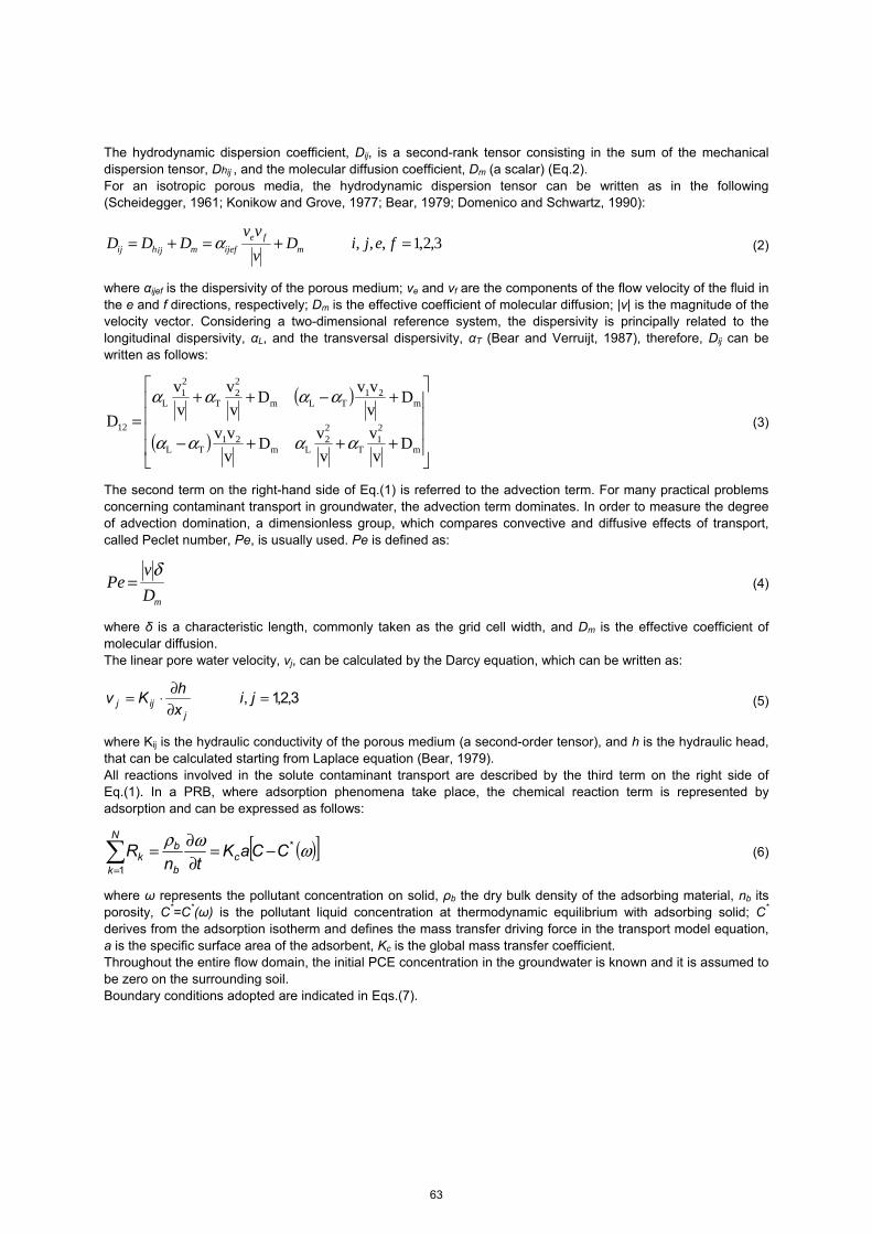
The hydrodynamic dispersion coefficient, Dij, is a second-rank tensor consisting in the sum of the mechanical dispersion tensor, Dhij , and the molecular diffusion coefficient, Dm (a scalar) (Eq.2). For an isotropic porous media, the hydrodynamic dispersion tensor can be written as in the following (Scheidegger, 1961; Konikow and Grove, 1977; Bear, 1979; Domenico and Schwartz, 1990):
3,2,1,,, =+=+= fejiDvvv
DDD mfe
ijefmijhij α (2)
where αijef is the dispersivity of the porous medium; ve and vf are the components of the flow velocity of the fluid in the e and f directions, respectively; Dm is the effective coefficient of molecular diffusion; |v| is the magnitude of the velocity vector. Considering a two-dimensional reference system, the dispersivity is principally related to the longitudinal dispersivity, αL, and the transversal dispersivity, αT (Bear and Verruijt, 1987), therefore, Dij can be written as follows:
( )
( )
+++−
+−++=
m
21
T
22
Lm21
TL
m21
TLm
22
T
21
L
12
Dvv
vvD
vvv
DvvvD
vv
vv
Dαααα
αααα (3)
The second term on the right-hand side of Eq.(1) is referred to the advection term. For many practical problems concerning contaminant transport in groundwater, the advection term dominates. In order to measure the degree of advection domination, a dimensionless group, which compares convective and diffusive effects of transport, called Peclet number, Pe, is usually used. Pe is defined as:
mDv
Peδ
= (4)
where δ is a characteristic length, commonly taken as the grid cell width, and Dm is the effective coefficient of molecular diffusion. The linear pore water velocity, vj, can be calculated by the Darcy equation, which can be written as:
3,2,1, =∂∂⋅= jix
hKv
jijj (5)
where Kij is the hydraulic conductivity of the porous medium (a second-order tensor), and h is the hydraulic head, that can be calculated starting from Laplace equation (Bear, 1979). All reactions involved in the solute contaminant transport are described by the third term on the right side of Eq.(1). In a PRB, where adsorption phenomena take place, the chemical reaction term is represented by adsorption and can be expressed as follows:
( )[ ]ωωρ *
1
CCaKtn
R cb
bN
kk −=
∂∂=
= (6)
where ω represents the pollutant concentration on solid, ρb the dry bulk density of the adsorbing material, nb its porosity, C*=C*(ω) is the pollutant liquid concentration at thermodynamic equilibrium with adsorbing solid; C*
derives from the adsorption isotherm and defines the mass transfer driving force in the transport model equation, a is the specific surface area of the adsorbent, Kc is the global mass transfer coefficient. Throughout the entire flow domain, the initial PCE concentration in the groundwater is known and it is assumed to be zero on the surrounding soil. Boundary conditions adopted are indicated in Eqs.(7).
63
( )
∀∀==∂∂−
∂∂
∂∂+
∂∂
∀∀=∀∀=∀∀=
=
t,xXxCvxx
CDxt
C
t,xYxt,xxt,xx
C
iij
iji
21
12
12
21
0
00
0 (7)
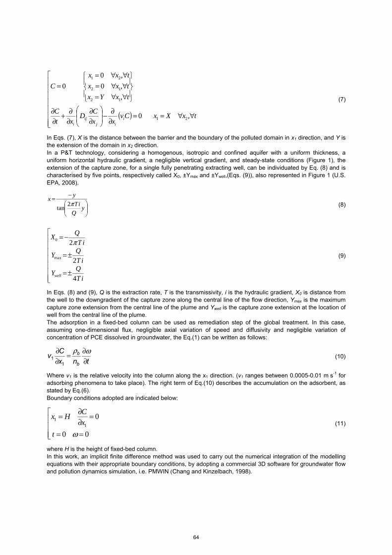
In Eqs. (7), X is the distance between the barrier and the boundary of the polluted domain in x1 direction, and Y is the extension of the domain in x2 direction. In a P&T technology, considering a homogenous, isotropic and confined aquifer with a uniform thickness, a uniform horizontal hydraulic gradient, a negligible vertical gradient, and steady-state conditions (Figure 1), the extension of the capture zone, for a single fully penetrating extracting well, can be individuated by Eq. (8) and is characterised by five points, respectively called X0, ±Ymax and ±Ywell,(Eqs. (9)), also represented in Figure 1 (U.S. EPA, 2008).
−=
yQ
iTyx
π2tan
(8)
±=
±=
−=
iTQY
iTQY
iTQX
well 4
2
2
max
0 π
(9)
In Eqs. (8) and (9), Q is the extraction rate, T is the transmissivity, i is the hydraulic gradient, X0 is distance from the well to the downgradient of the capture zone along the central line of the flow direction, Ymax is the maximum capture zone extension from the central line of the plume and Ywell is the capture zone extension at the location of well from the central line of the plume. The adsorption in a fixed-bed column can be used as remediation step of the global treatment. In this case, assuming one-dimensional flux, negligible axial variation of speed and diffusivity and negligible variation of concentration of PCE dissolved in groundwater, the Eq.(1) can be written as follows:
tnx
Cv
b
b
∂∂=
∂∂ ωρ
11 (10)
Where v1 is the relative velocity into the column along the x1 direction. (v1 ranges between 0.0005-0.01 m s-1 for adsorbing phenomena to take place). The right term of Eq.(10) describes the accumulation on the adsorbent, as stated by Eq.(6). Boundary conditions adopted are indicated below:
==
=∂∂=
00
01
1
ωtxCHx
(11)
where H is the height of fixed-bed column. In this work, an implicit finite difference method was used to carry out the numerical integration of the modelling equations with their appropriate boundary conditions, by adopting a commercial 3D software for groundwater flow and pollution dynamics simulation, i.e. PMWIN (Chang and Kinzelbach, 1998).
64

In particular, the Darcy equation (Eq.(5)) and the Laplace equation were solved by PMWIN-MODFLOW toolbox, while the mass transport equation (Eq.(1)) was solved by PMWIN-MT3D toolbox (Erto et al., 2011a). A second code called ADSORB-CODE was developed to describe the adsorption phenomena involving the pollutant both for PRB and P&T, in which Eqs.(6) and (10) were solved with the boundary conditions in Eqs.(7) and (11), respectively, after the individuation of a specific adsorbent material for PCE removal from polluted groundwater.
Figure 1: Capture zone area for a single fully penetrating pumping well
2.2 Absorbing material characterization A granular activated carbon (GAC), commercially available, the Aquacarb 207EATM (provided by Sutcliffe Carbon,) was chosen as adsorbing material. This GAC has the following characteristics: a BET surface area of 950 m2 g-1, an average pore diameter of 26 Å, a dry bulk density (ρb) of 500 kg m-1, a porosity (nb) of 0.4 and a hydraulic conductivity of about 0.001 m s-1. The experimental characterization of the GAC for PCE adsorption was reported in previous papers (Erto et al., 2009; Erto et al., 2010; Erto et al., 2011b), and the Langmuir adsorption equation showed to be the most suitable isotherm model:
( )( )ωωω
ω*
*max
1 CK
CK
⋅+⋅
= (12)
Where ωmax is the maximum adsorption capacity and K is the Langmuir equilibrium constant. At a temperature of 10 °C, the following parameters were estimated for Eq.(12): ωmax = 913.9 mg/g K = 19.830 l/mol.
3. Case study
A PCE-contaminated aquifer near a solid waste landfill in Giugliano in Campania, in the metropolitan area North of Naples (Italy), was examined as a case study. In this area (2.25 km2), several solid landfills are located and an enormous amount of solid wastes was deposited in the last decades. A complete characterization of the
65
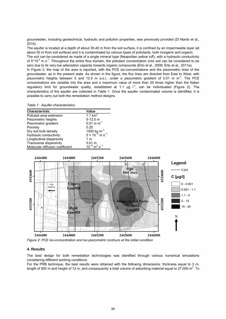
groundwater, including geotechnical, hydraulic and pollution properties, was previously provided (Di Nardo et al., 2010). The aquifer is located at a depth of about 35-40 m from the soil surface, it is confined by an impermeable layer (at about 50 m from soil surface) and it is contaminated by various types of pollutants, both inorganic and organic. The soil can be considered as made of a single mineral type (Neapolitan yellow tuff), with a hydraulic conductivity of 5*10-5 m s-1. Throughout the entire flow domain, the pollutant concentration onto soil can be considered to be zero due to its very low adsorption capacity towards organic compounds (Erto et al., 2009; Erto et al., 2011a). In Figure 2, the map of the area is reported, with the PCE iso-concentrations and the piezometric lines of the groundwater, as in the present state. As shown in the figure, the flux lines are directed from East to West, with piezometric heights between 5 and 12.5 m a.s.l., under a piezometric gradient of 0.01 m m-1. The PCE concentrations are variable into the area and a maximum value of more than 20 times higher than the Italian regulatory limit for groundwater quality, established at 1.1 μg l-1, can be individuated (Figure 2). The characteristics of the aquifer are collected in Table 1. Once the aquifer contaminated volume is identified, it is possible to carry out both the remediation method designs.
Table 1: Aquifer characteristics
Characteristic ValuePolluted area extension 1.1 km2 Piezometric heights 5-12.5 m Piezometric gradient 0.01 m m-1 Porosity 0.25 Dry soil bulk density 1500 kg m-3 Hydraulic conductivity 5 × 10⁻⁵ m s−1 Longitudinal dispersivity 1 m Transverse dispersivity 0.01 m Molecular diffusion coefficient 10−8 m2 s−1
Figure 2: PCE iso-concentration and iso-piezometric contours at the initial condition
4. Results
The best design for both remediation technologies was identified through various numerical simulations considering different working conditions. For the PRB technique, the best results were obtained with the following dimensions: thickness equal to 3 m, length of 900 m and height of 12 m, and consequently a total volume of adsorbing material equal to 27,000 m3. To
66
achieve the best capture efficiency of the contaminated plume, the permeable wall is placed perpendicularly to the groundwater flow. In Figure 3, the numerical results of the remediation simulation by PRB are reported. As can be observed, during a working period of about 60 years, the out-flowing PCE concentration is always lower than the Italian regulatory limit, also taking into account possible occurrence of desorbing phenomena from GAC to groundwater. For the P&T technique, instead, the best results were obtained with a configuration of 27 pumping wells and 12 recharge wells (Figure 4). As shown, after a run period of about 35 years, the PCE concentration is everywhere lower than the Italian regulatory limit, and, consequently, the whole groundwater volume results to be decontaminated. In the adopted well configuration, when the PCE concentration reaches a value lower than the regulatory limit, a progressive turning off of the pumping wells in the pertinent zone can be adopted. Similarly, when the increment of water level is no longer necessary for the extraction process, some recharge wells can be turned off too. Pumped and recharged water flow rate trends are reported in Figure 5. For the working time considered, the total amount of pumped water resulted to be about 1,500,000 m3; while the total amount of recharged water was about 600,000 m3. As it can be observed, water recharge ended after 30 years of operation. Two adsorption columns were chosen by CFD simulations to treat this water volume, each with a height of 2.5 m, a diameter of about 0.2 m, and a working time of 15 days (after which the absorbing material into the column is regenerated/substituted). In addition, a preliminary cost analysis for the PRB and the P&T systems dimensioned, was carried out. The costs of the main variables considered for both PRB and P&T, and the corresponding amounts, are reported in Table 2 and Table 3, respectively. According to this cost analysis, it is not possible to establish clearly which is the most cost-effective remediation method for the case study presented. This is mainly due to the wide margin of uncertainty in the unit cost of the main variables examined; consequently a more accurate site-specific cost analysis is required. In any case, for the PRB, the cost of adsorbing material exceeds the 70% of the total cost; therefore using a low cost adsorbent material could make this technique cheaper than the P&T, as previously observed.
Table 2: Preliminary cost analysis for PRB (service life about 60 years)
Cost variables Unit cost Amount Cost [€] Construction 50-100 [€/m3
soil] 27,000 [m3soil] 1,350,000-2,700,000
Adsorbing material 100-500 [€/m3GAC] 27,000 [m3
GAC] 2,700,000-13,500,000 Monitoring - - 100,000-250,000 Total: 4,150,000-16,450,000
Table 3: Preliminary cost analysis for P&T (service life about 35 years)
Cost variables Unit cost Amount Cost [€]Construction 0.2-0.4 [€/m3
flow] 1,500,000 [m3flow] 300,000-600,000
Energy 0.1-0.2 [€/kWh] 280,000 [kWh] 28,000-56,000 Workers 20,000-30,000 [€/year] 6 4,200,000-6,300,000 Treatment 1-5 [€/m3
flow] 1,500,000 [m3flow] 1,500,000-7,500,000
Monitoring - - 100,000-250,000 Total: 6,128,000-14,706,000
5. Conclusion
In this work, a comparison between Pump & Treat technique and Permeable Reactive Barriers for the remediation of a PCE-contaminated aquifer was carried out, and a preliminary cost analysis was reported. Both decontamination technologies were applied to a polluted site in the metropolitan area North of Naples (Italy) and adsorption was chosen as remediation technology. The design was carried out using Computational Fluid Dynamics (CFD) by adopting specific software for groundwater flux simulation and adsorption phenomena onto activated carbon. Numerical results showed that both PRB and P&T can be suitable to remediate the polluted aquifer considered, reducing PCE concentration under the regulatory limit, and therefore respecting water quality standards.
67
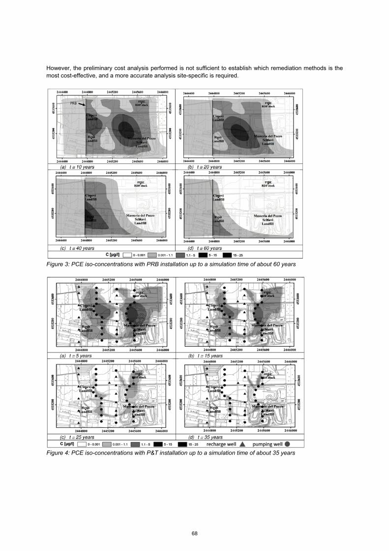
However, the preliminary cost analysis performed is not sufficient to establish which remediation methods is the most cost-effective, and a more accurate analysis site-specific is required.
Figure 3: PCE iso-concentrations with PRB installation up to a simulation time of about 60 years
Figure 4: PCE iso-concentrations with P&T installation up to a simulation time of about 35 years
68

Figure 5: Pumped and Recharged Flow rates during the P&T working time
References
Anderson M.P., 1984, Movement of contaminants in groundwater: groundwater transport-advection and dispersion. Groundwater Contamination. National Academy Press, Washington, D. C.
Bear J., 1979, Hydraulics of Groundwater, McGraw-Hill, New York, United States of America. Bear J., Verruijt A., 1987, Modelling Groundwater Flow and Pollution. Reidel Publishing Co., Dordrecht, Holland. Bembnowska A., Pelech R., Milchert E., 2003, Adsorption from aqueous solutions of chlorinated organic
compounds onto activated carbon, J. Colloid Interface Sci., 265, 276–282. Chiang W.H., Kinzelbach W., 1998., Processing Modflow: A simulation system for modeling groundwater flow and
pollution, US Geological Survey, available at http://www.pmwin.net. Di Nardo A., Di Natale M., Erto A., Musmarra D., Bortone I., 2010, Permeable reactive barrier for groundwater
PCE remediation: The case study of a solid waste landfill pollution, Computer Aided Chemical Engineering, 28 (C) 1015-1020.
Di Natale F., Di Natale M., Greco R., Lancia A., Laudante C., Musmarra D., 2008, Groundwater protection from cadmium contamination by permeable reactive barriers, J. Hazard. Mater., 160 (2-3) 428-434.
Domenico P.A. and Schwartz F. W., 1990, Physical and Chemical Hydrogeology. John Wiley and Sons, New York.
Erto A., Andreozzi R., Di Natale F., Lancia A., Musmarra D., 2009, Experimental and isotherm-models analysis on TCE and PCE adsorption onto activated carbon, Chemical Engineering Transactions, 17, 293-298, DOI: 10.3303/CET0917050.
Erto A., Andreozzi R., Lancia A., Musmarra D., 2010, Factors affecting the adsorption of trichloroethylene onto activated carbons, Appl. Surf. Sci., 256 (17), 5237-5242.
Erto A., Lancia A., Bortone I., Di Nardo A., Di Natale M., Musmarra D., 2011a, A procedure to design a Permeable Adsorptive Barrier (PAB) for contaminated groundwater remediation, J. Environ. Manage., 92 (1), 23-30.
Erto A., Lancia A., Musmarra D., 2011b, A modelling analysis of PCE/TCE mixture adsorption based on Ideal Adsorbed Solution Theory, Sep. Purif. Technol., 80 (1), 140-147.
Erto A., Lancia A., Musmarra D., 2012, A Real Adsorbed Solution Theory model for competitive multicomponent liquid adsorption onto granular activated carbon, Micropor. Mesopor. Mat., 154, 45-50.
69
Fiore S., Zanetti M., 2006, Degradation of trichloroethylene and perchloroethylene by a zero-valent iron permeable reactive barrier: Preliminary tests, International Journal of Sustainable Development and Planning, 1 (4) 476-491.
IARC, 1995, Monographs on the evaluation of carcinogenic risks to humans, vol. 63: dry cleaning, some chlorinated solvents and others industrial chemicals, Lyon, France.
Jun D., Yongsheng Z., Weihong Z., Mei H., 2009, Laboratory study on sequenced permeable reactive barrier remediation for landfill leachate-contaminated groundwater, J. Hazard. Mater. 161 (1), 224-230.
Kjeldsen P., Barlaz M.A., Rocker A.P., Baun A., Ledin A., Christensen T.H., 2002, Present and long-term composition of MSW landfill leachate: a review, Crit. Rev. Env. Sci. Tech. 32 (4), 297-336.
Ko S., Crimi M., Marvin B.K., Holmes V., Huling S.G., 2012, Comparative study on oxidative treatments of NAPL containing chlorinated ethanes and ethenes using hydrogen peroxide and persulfate in soils, J. Environ. Manage., 108, 42-48.
Konikow L.F., Grove D.B., 1977, Derivation of Equations Describing Solute Transport in Ground Water. US Geol. Survey Water-Res. Inv. 77-19.
Lai K.C.K., Lo I.M.C., Birkelund V., Kjeldsen P., 2006, Field monitoring of a permeable reactive barrier for removal of chlorinated organics, J. Environ. Eng-Asce., 132, (2), 199-210.
Molino A., Erto A., Di Natale F., Donatelli A., Iovane P., Musmarra D., 2013, Gasification of granulated scrap tires for the production of syn-gas and a low cost adsorbent for Cd(II) removal from waste waters, Ind. Eng. Chem. Res., 52 (34), 12154–12160.
Muchitsch N., Van Nooten T., Bastiaens L., Kjeldsen P., 2011, Integrated evaluation of the performance of a more than seven year old permeable reactive barrier at a site contaminated with chlorinated aliphatic hydrocarbons (CAHs), J. Contam. Hydrol., 126 (3-4), 258-270.
Plagentz V., Ebert M., Dahmke A., 2006, Remediation of ground water containing chlorinated and brominated hydrocarbons, benzene and chromate by sequential treatment using ZVI and GAC, Environ. Geol., 49 (5) 684-695.
Pelech P., Bembnowska A., Milchert E., 2003, Adsorption of hydrocarbon chloro-derivatives onto DTO commercial carbon from multi-component aqueous solutions, Adsorp. Sci. Technol., 21 (8), 707–720.
Rivett M.O., Chapman S.W., Allen-King R.M., Feenstra S., Cherry J.A., 2006, Pump-and-treat remediation of chlorinated solvent contamination at a controlled field-experiment site, Environ. Sci. Technol., 40 (21), 6770-6781.
Scheidegger A.E., 1961, General theory of dispersion in porous media, J. Geophys. Res., 66 (10), 3273-3278. Suzuki M., 1990, Adsorption Engineering, Elsevier, Amsterdam. U.S. EPA, 1988, Updated Health Assessment Document for Tetrachloroethylene, U.S. Environmental Protection
Agency, EPA/600/8e82/005B, Washington, United States of America. U.S. EPA, 1996, Pump-and-Treat Ground-Water Remediation, U.S. Environmental Protection Agency,
EPA/625/R-95/005, Washington, United States of America. U.S. EPA, 2008, A Systematic Approach for Evaluation of Capture Zones at Pump and Treat Systems, U.S.
Environmental Protection Agency, EPA/600/R-08/003, Washington, United States of America.
70