A Closer Look at RF Power Measurements - · PDF filegy conversion, it then attempts to ... use...
3
44 DECEMBER 2014 MICROWAVES & RF POWER IS IMPORTANT. Measuring the power from an RF/microwave signal is a fundamental way to gain knowledge about signals and devices. Understand- ably, it is critical to accurately and consistently mea- sure power. It also is essential to maintain a standard of power measurement that enables measured power to be communicated to customers, manufacturers, designers, and researchers. There are three main technologies involved in measuring RF/microwave power: the diode, thermistor, and thermocouple sen- sor. Each product type comes with its own benefits and uncertainties. Addi- tionally, industry and manufacturer standards for power-measurement calibration need to be employed successfully to communicate absolute val- ues of power (namely, the National Institute of Stan- dards and Technology and other National Measure- ment Institutes). Having a clear understanding of the fundamentals of power measurement, including the technology and stan- dards, will ensure that an engineer has the most reli- able information for opti- mizing their designs. The goal of a power sensor, for example, is to absorb the incoming ener- gy from an RF/microwave signal. By relying on ener- gy conversion, it then attempts to transfer that energy into usable electrical energy that exactly replicates the absorbed energy. Of course, some energy is always lost in the impedance mismatch between the source and sensor. In addition, some energy is absorbed in parts of the sensor that do not render usable electrical ener- gy. The meter itself also suffers from some conversion inefficiencies. Fortunately, however, there are calibra- tions provided by power-meter manufacturers that use a chart or built-in memory to help compensate for the sensor and meter inefficiencies. A Closer Look at RF Power Measurements Because measuring RF/microwave power is one of the most commonly used methods of understanding system performance, detailed knowledge of how power measurements are made is key to successfully interpreting measurement results. RF Essentials JEAN-JACQUES DELISLE | Technical Engineering Editor 1. This microwave-sensor approach used silicon crystals with a curled tungsten wire, which touched the surface of the silicon functioning as a diode. Pin end Ceramic case Tungsten whisker Hole in ceramic for wax filling Silicon Head Screw for adjustment at assembly Screw for adjustment at assembly Two set screws to hold adjustment a) Sylvania b) Western Electric
Transcript of A Closer Look at RF Power Measurements - · PDF filegy conversion, it then attempts to ... use...
44 DECEMBER 2014 MICROWAVES & RF
POWER IS IMPORTANT. Measuring the power from an RF/microwave signal is a fundamental way to gain knowledge about signals and devices. Understand-ably, it is critical to accurately and consistently mea-sure power. It also is essential to maintain a standard of power measurement that enables measured power to be communicated to customers, manufacturers, designers, and researchers. There are three main technologies involved in measuring RF/microwave power: the diode, thermistor, and thermocouple sen-sor. Each product type comes with its own benefits and uncertainties. Addi-t ional ly, industr y and manufacturer standards for power-measurement calibration need to be employed successfully to communicate absolute val-ues of power (namely, the National Institute of Stan-dards and Technology and other National Measure-ment Institutes). Having a clear understanding of the fundamentals of power measurement, including the technology and stan-dards, will ensure that an engineer has the most reli-able information for opti-mizing their designs.
The goal of a power sensor, for example, is to absorb the incoming ener-gy from an RF/microwave signal. By relying on ener-
gy conversion, it then attempts to transfer that energy into usable electrical energy that exactly replicates the absorbed energy. Of course, some energy is always lost in the impedance mismatch between the source and sensor. In addition, some energy is absorbed in parts of the sensor that do not render usable electrical ener-gy. The meter itself also suffers from some conversion inefficiencies. Fortunately, however, there are calibra-tions provided by power-meter manufacturers that use a chart or built-in memory to help compensate for the sensor and meter inefficiencies.
A Closer Look at RF Power MeasurementsBecause measuring RF/microwave power is one of the most commonly used methods of understanding system performance, detailed knowledge of how power measurements are made is key to successfully interpreting measurement results.
RF EssentialsJEAN-JACQUES DELISLE | Technical Engineering Editor
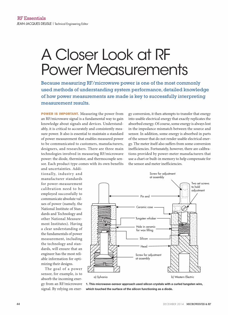
1. This microwave-sensor approach used silicon crystals with a curled tungsten wire,
which touched the surface of the silicon functioning as a diode.
Pin end
Ceramic case
Tungsten whisker
Hole in ceramicfor wax filling
Silicon
Head
Screw for adjustmentat assembly
Screw for adjustment at assembly
Two set screws to hold adjustment
a) Sylvania b) Western Electric

GO TO MWRF.COM 45
AN OLD-TIMEY THERMISTOR,
STILL IN DEMAND
Of the three types of sensor technologies, the thermistor—a type of bolometer—has been around the longest. It is still used in many applications including science and research. The thermistor sensor converts RF/microwave energy received by a semiconductor-based material, which changes resistance as a function of temperature (Fig. 1).
In addition, a feedback loop is used with a balanced-bridge typology. That typology employs a direct-current (DC) or alternating-current (AC) bias supply as a control to main-tain a constant resistance for the sensor. As a result, the
changes in bias power can be used as an indicator for the energy absorbed in the sensor.
LOWER ERROR WITH
THERMOCOUPLE SENSORS
In many of today’s applications, thermocouple sensors have replaced thermistors. This trend is most likely due to the advantages offered by thermocouple sensors: higher dynamic range, sensitivity, increased durability, and lower measurement uncertainties associated with standing wave ratio (SWR). Thermocouple operation relies on two physical bases—the first of which uses the voltage generated from the
Peltier effect at the junction of two elec-trically dissimilar materials.
The other base leverages the Thom-son effect at the junction of two dif-ferent temperature sections of a con-ductor. Currently, metallic thin-film and semiconductor technology are used to create high-performing and l i n e a r t h e r m o c o u p l e s i n v e r y small footprints.
A transmission method is often employed to enable use of the extreme-ly low voltage—sometimes as low as 1 nV/mW—generated by the thermo-couple. One method is to chop the DC signal into a series of square waves and transmit that over an AC-coupled path after amplification (Fig. 2).
B e c aus e t h i s i s an op en- lo op approach, an outside calibration meth-od must be used. Otherwise, various aspects of the thermocouple sensor can lead to drift in the DC response to RF/microwave power.
Often, a highly accurate reference oscillator set to a specific known power is used between tests to calibrate the thermocouple-based sensor to match the reference source. Errors in the ref-erence source, calibration mechanisms, or interconnect of the source and sen-sor can lead to measurement errors. It is therefore critical for the reference to
Peak powerPulse-top amplitude Overshoot
PRF
Fall timeRise time
Pulse width
Duty cycle PRI
Pulse-base amplitude
Off time
Pulsedelay
Averagepower
2. The response characteristics of a pulsed signal are detailed in order to properly describe the
signal behavior for interpretation. (Courtesy of Keysight Technologies)
“To achieve the lowest error possible for any of the measurement technologies, it is critical to account for the error in each stage of
the sensor and meter process.”
Down Linkpreamble Down Link
data transmission
3. Modern power meters can intelligently trigger on wireless protocols to properly assess
wireless-device operational performance. (Courtesy of LadyBug Tech)

46 DECEMBER 2014 MICROWAVES & RF
have as little error as possible as well as a verifiable trace his-tory to a credible NMI.
DIODE DETECTION
GROWS IN POPULARITY
Another power-measuring technology that is becoming more viable is the diode detector. The nonlinear current and voltage relationship within a diode, which stems from the junction properties, allows the flow of current through a par-ticular path of the device.
At the same time, it resists the flow of current in the oppo-site direction. This behavior makes it possible to derive a positive waveform using multiple diodes—a process known as rectification.
Diode technologies, such as low-barrier-shottky (LBS) and planar-doped-barrier (PDB) diodes, have very low internal capacitance and low forward voltage. As a result, they can respond well to very rapidly changing signals (Fig. 3). With advanced micro-fabrication techniques, these devices can be produced with a high level of consistency and reliability at relatively low costs.
Although many diode detectors are limited in the higher power regimes—beyond the −20 dBm level in which ther-mocouple sensors can accurately operate—diode sensors are often capable of accurate sensing down to −70 dBm. Thus, they are often chosen for high-sensitivity and high-frequency power measurements.
The resistance at the terminal of an LBS diode is high for low-signal levels and varies significantly with temperature. Consequently, additional matching circuitry may be required to achieve reliable results.
PDB diodes generally have consistent and much lower resistances than LBS diodes. They also boast lower internal capacitance, which leads to more stable square-law region behavior and a higher operating range.
With enhanced fabrication techniques, some diode sensors have reached 90 dB in dynamic range. This range is suit-able for continuous-wave (CW) sensing into the millimeter-wave frequencies. Additional circuitry can be added to the
diode power sensor on a monolithic- microwave-integrated-circuit (MMIC) substrate, which will allow advanced correct ions to be appl ied to fur-ther increase the diode-sensor device performance.
To enable averaging power mea-surements, it is possible to use a high- sensitivity and low-sensitivity path
connected to a splitter and then to the source (Fig. 4).
ERROR & UNCERTAINTY
To maintain a common ground for power-measurement standards, NMI organizations have prescribed methods of obtaining calibration-standard traceability. These standards often start with extremely accurate micro-calorimeter stan-dards. They are then transferred to working standards and on to measurement reference standards used by commercial standards laboratories. From there, they are transferred to manufacturing facilities and lastly to test equipment.
Each stage in the standards-transfer process adds error, which is compounded by the sensor, meter, and mismatch error present in the power meter. Often, a power-splitter technique is used with a reference power meter and a power meter awaiting calibration. This approach, known as the power-ratio method, allows the power meters to be adjusted to relatively equivalent operation.
Yet the asymmetries in the splitter calibration often add more error to the meter. More complex methods are needed to appropriately calibrate a peak-power sensor, as the micro-calorimeter sensor is an averaging sensor base.
To achieve the lowest error possible for any of the measure-ment technologies, it is critical to account for the error in each stage of the sensor and meter process. Precision assem-blies can help to reduce the impedance mismatch between the sensor and source. In addition, multiple sensors can sometimes be used to mitigate the effects of bias, ambient temperature, and noise factors.
A variety of power-measurement technologies extend from bench-top to rack-mount power-measurement devices. Network analyzers, spectrum analyzers, and many other test and measurement instruments utilize power sensors in order to translate RF/microwave signals into human-relatable terms. One must keep in mind that the different techniques, technologies, and methods of power sensing may be better suited to measuring different power levels, frequencies, and modulations of signals.
As a result, having a deep understanding of the exact sig-nals under scrutiny and available measurement techniques could aid in delivering an adequate quality result.
Measuring Power
RF in Splitter
High-sensitivity path
Low-sensitivity path
Video BW Filter
Video BW Filter
ADC
ADC
Sampling trigger Processor
4. The modulation schemes common to the wireless industry may have extremely high peak-
to-average power ratios. As a result, multipath diode sensors with high and low sensitivity
paths can be used to measure average power. (Courtesy of Tektronix)