A CASE STUDY ON THE STRUCTURAL ANALYSIS AND FRAGILITY ...
10
Transactions, SMiRT-25 Charlotte, NC, USA, August 4-9, 2019 Division V A CASE STUDY ON THE STRUCTURAL ANALYSIS AND FRAGILITY CALCULATION DUE TO SEISMIC IMPACT BETWEEN ADJACENT STRUCTURES Asa Bassam 1 , Ben Kosbab 1 , Payman Tehrani 2 , Hamed Ebrahimian 3 1 Principal Engineer, SC Solutions, Inc, Marietta, GA, USA 2 Principal Engineer, SC Solutions, Inc, Sunnyvale, CA, USA 3 Senior Engineer, SC Solutions, Inc, Sunnyvale, CA, USA ABSTRACT In this study, the seismic impact between two adjacent structures with different lateral stiffness is investigated through a computational model. The method used for the impact analysis in this study is based on the Hertz contact law combined with a non-linear damper activated during the impact to allow consideration of energy dissipation during the impact period. The selected analysis method is explicit time domain due to transient and non-linear nature of impact. The analysis explicitly includes the soil domain and structures, integrated in a single Finite Element (FE) model. Response history analyses are performed for various ground motions, and results are extracted in terms of impact force and acceleration response at various locations within the structures. The effect of uncertainties in local stiffness of concrete components in the impact zone are investigated to demonstrate the sensitivity of the results to variability of the impact parameters. As the impact force is found to be high enough to potentially cause structural damage, the seismic fragility of the external shear wall most susceptible to damage in the impact interface is also evaluated. Even though the mass of the two buildings in this study are on the same order, the seismic impact is shown to cause negligible changes in the In-Structure Response Spectra (ISRS) of the stiffer structure while significantly increasing the ISRS amplitudes of the more flexible structure. INTROCUCTION Nuclear facilities are often comprised of several major structures built in immediate proximity to each other, with seismic “shake-space” provided in between to minimize the likelihood of building-to-building collision occurring during a design basis earthquake. However, at some larger earthquake such as could be considered in a seismic probabilistic risk assessment (SPRA) or seismic margin assessment (SMA), relative deformation of adjacent buildings can “close the gap” between structures, resulting in impact/pounding between the buildings. Building impact has the potential to be detrimental in two primary ways: (1) impact loads resulting in local structural damage to impacting elements; and/or (2) impact events changing the seismic demands on components housed inside the impacting structures. A particular concern with building impact is that it has been found to result in large-amplitude high- frequency acceleration responses, somewhat resembling “shock” spectra; high-frequency spectral accelerations from structures exhibiting building impact can be tens of times higher than those from seismic shaking by itself, and can propagate some distance away from the impact location [Wolf and Skrikerud (1979), Kasai et al. (1990), Kasai et al. (1992)]. These high-frequency accelerations have the potential to cause equipment malfunction, especially contact-sensitive components such as relays.
Transcript of A CASE STUDY ON THE STRUCTURAL ANALYSIS AND FRAGILITY ...

Transactions, SMiRT-25 Charlotte, NC, USA, August 4-9, 2019
Division V
A CASE STUDY ON THE STRUCTURAL ANALYSIS AND FRAGILITY CALCULATION DUE TO SEISMIC IMPACT BETWEEN ADJACENT
STRUCTURES
Asa Bassam1, Ben Kosbab1, Payman Tehrani2, Hamed Ebrahimian3 1 Principal Engineer, SC Solutions, Inc, Marietta, GA, USA 2 Principal Engineer, SC Solutions, Inc, Sunnyvale, CA, USA 3 Senior Engineer, SC Solutions, Inc, Sunnyvale, CA, USA ABSTRACT In this study, the seismic impact between two adjacent structures with different lateral stiffness is investigated through a computational model. The method used for the impact analysis in this study is based on the Hertz contact law combined with a non-linear damper activated during the impact to allow consideration of energy dissipation during the impact period. The selected analysis method is explicit time domain due to transient and non-linear nature of impact. The analysis explicitly includes the soil domain and structures, integrated in a single Finite Element (FE) model. Response history analyses are performed for various ground motions, and results are extracted in terms of impact force and acceleration response at various locations within the structures. The effect of uncertainties in local stiffness of concrete components in the impact zone are investigated to demonstrate the sensitivity of the results to variability of the impact parameters. As the impact force is found to be high enough to potentially cause structural damage, the seismic fragility of the external shear wall most susceptible to damage in the impact interface is also evaluated. Even though the mass of the two buildings in this study are on the same order, the seismic impact is shown to cause negligible changes in the In-Structure Response Spectra (ISRS) of the stiffer structure while significantly increasing the ISRS amplitudes of the more flexible structure. INTROCUCTION Nuclear facilities are often comprised of several major structures built in immediate proximity to each other, with seismic “shake-space” provided in between to minimize the likelihood of building-to-building collision occurring during a design basis earthquake. However, at some larger earthquake such as could be considered in a seismic probabilistic risk assessment (SPRA) or seismic margin assessment (SMA), relative deformation of adjacent buildings can “close the gap” between structures, resulting in impact/pounding between the buildings. Building impact has the potential to be detrimental in two primary ways: (1) impact loads resulting in local structural damage to impacting elements; and/or (2) impact events changing the seismic demands on components housed inside the impacting structures.
A particular concern with building impact is that it has been found to result in large-amplitude high-frequency acceleration responses, somewhat resembling “shock” spectra; high-frequency spectral accelerations from structures exhibiting building impact can be tens of times higher than those from seismic shaking by itself, and can propagate some distance away from the impact location [Wolf and Skrikerud (1979), Kasai et al. (1990), Kasai et al. (1992)]. These high-frequency accelerations have the potential to cause equipment malfunction, especially contact-sensitive components such as relays.
25th Conference on Structural Mechanics in Reactor Technology
Charlotte, NC, USA, August 4-9, 2019 Division V
In some cases, it may be possible to evaluate the building impact for beyond-design-basis earthquakes rather simplistically and screen from further consideration. However, depending on the consequence and significance of the impact, which are case specific, simple assessments are not always sufficient to demonstrate that significant impact won’t occur. The latter is due to limitations of reliable methods to approximate impact effects with simple tools due to the sensitivity of such predictions to both physical and numerical details. In such cases, rigorous analyses considering case-specific considerations and details, including explicit modelling of the impacting bodies and their dynamic interaction during the impact is preferred. The case study described in this paper is one such case where impact between adjacent buildings required analysis of the impact scenario.
This paper demonstrates the development and utilization of an explicit analysis model of two adjacent
buildings which are likely to impact each other during large earthquakes, to estimate the effect of building impact on both (a) seismic demands on components housed in each building, and (b) local structural damage caused by impact. While the model and analysis are case-specific, the techniques and methods used are universal, and could be applied to a wide range of similar cases. THEORETICAL BACKGROUND AND BASIS Hertz contact law [Goldsmith (1960)] has been utilized by many researchers in the past to study the building pounding behaviour (e.g., Wolf and Skrikerud (1979), Anagnostopoulos (1988), Pantelides and Ma (1998), Chau and Wei (2001), Muthukumar and DesRoches (2006), and Ye et al. (2009)). A major limitation of the Hertz contact law is its inability to consider energy dissipation during impact. The method used in this study is a hybrid approach in which the Hertz contact law is used together with a non-linear damper activated during the approach period of impact to simulate the energy dissipation. The pounding force during impact, 𝐹 𝑡 , is calculated using a nonlinear viscoelastic model based on Jankowski (2005) as:
𝐹 𝑡 𝐾 𝛿 𝑡 𝐶 𝑡 𝛿 𝑡 for 𝛿 𝑡 0 (approach period) (1)
𝐹 𝑡 𝐾 𝛿 𝑡 for 𝛿 𝑡 0 (restitution period) (2) Where 𝐾 is the impact stiffness parameter, 𝐶 𝑡 is the impact element’s damping coefficient, and
𝛿 𝑡 and 𝛿 𝑡 denote the relative deformation and relative velocity of the impact element ends upon closure of the gap, respectively. The following subsections define the above-mentioned parameters.
In the absence of relevant large-scale experimental data involving concrete-to-concrete collisions,
the procedure provided in Goldsmith (1960) is used in this study to calculate the stiffness parameter (𝐾 ). For elastic contact between two isotropic spheres of radii 𝑅 and 𝑅 , 𝐾 can be expressed as follows:
𝐾/
(3)
Where ℎ and ℎ are material parameters defined as
ℎ (4)
And 𝜈 and 𝐸 are the Poisson’s ratio and modulus of elasticity, respectively, of sphere i. The
equivalent radius of each colliding body can be estimated as
𝑅 (5)

25th Conference on Structural Mechanics in Reactor Technology
Charlotte, NC, USA, August 4-9, 2019 Division V
Where 𝑚 and 𝜌 are the mass and density of the colliding body, respectively. 𝐶 𝑡 in Equation (1) can be obtained as [Jankowski (2005)]:
𝐶 𝑡 2𝜉 𝐾 𝛿 𝑡 (6)
Where 𝑚 and 𝑚 are the mass of the colliding bodies and 𝜉 denotes the damping ratio related to the
coefficient of restitution 𝑒, and can be approximated as [Jankowski (2006)]:
𝜉 √ (7)
The coefficient of restitution, e is a function of velocity prior to the impact and the material properties
of the impacting bodies and is derived based on experimental data [Jankowski (2007)]. For example, for two concrete bodies with maximum impact velocity of about 0.5 m/s, the coefficient of restitution is about 0.65.
For impact problems involving multi-degree-of-freedom systems with non-uniform geometry, such as is the case for impacting buildings, the colliding mass at each impact element cannot be precisely determined. As an approximation, parameters 𝑚 and 𝑚 , which are used for the stiffness and damping factor estimation in Equations (5) and (6), are estimated based on the mass of the impacting bodies at each slab elevation including the total mass of the slab plus half height of the walls and columns above and below in each building. This approximation is a common practice in the literature (e.g., Jankowski (2004)).
CASE STUDY MODEL DESCRIPTION In this study, the seismic impact between a relatively flexible structure (i.e., a Turbine Building (TB) with pile foundations in soft soil) and a relatively stiffer structure (i.e., a Reactor Building (RB) with slab foundation on hard rock) in a nuclear power plant (NPP) is investigated through a computational model as part of a seismic probabilistic risk assessment (SPRA) of the plant. The scenario of adjacent structures with significantly different dynamic properties and insufficient seismic gap to preclude impact during beyond-design-basis earthquakes is not uncommon for NPPs. For the subject NPP, review of design basis TB soil-structure interaction (SSI) analysis results demonstrated that the lateral seismic response of the building is mainly governed by flexibility of the underlying soil/pile foundation system and a dominant frequency lower than 1 Hz. Estimated spectral displacements at this dominant frequency suggested that TB seismic lateral displacements for the SPRA hazard range of interest are likely to exceed the gap size between the RB and TB and thus, may result in impact/pounding with the Reactor Building (RB). Therefore, an impact analysis is performed to investigate the effect of seismic impact on the ISRS at the areas where impact-sensitive equipment are in the vicinity of the impact zone. The impact analysis utilized an integrated FE model which explicitly includes the soil domain, TB and its pile foundation system, RB, and their interactions. Equivalent linear properties are used to simulate both the structures and the soil domain. However, nonlinear impact elements are used to simulate potential collision. The following paragraphs provide a brief description of the model:
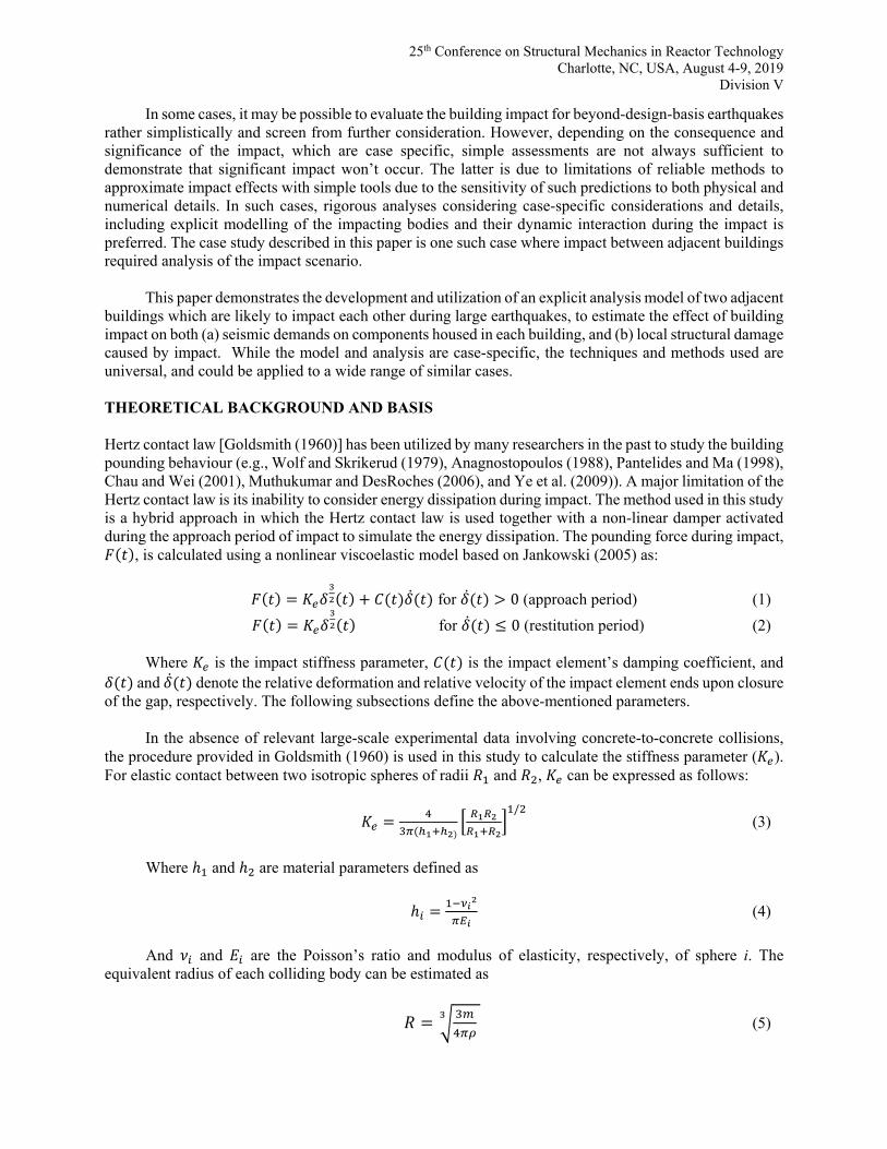
The TB concrete structure has three main parts. Part 1 is a rectangular building next to the RB. It is separated from the RB through a 2-inch expansion joint. Part 2 is the TB pedestal. Part 3 is a U-shaped structure surrounding the TB pedestal. The TB foundation utilizes steel piles that extend through the in-situ soil to the bedrock. For simplicity, the TB Parts 2 and 3 are modelled with linear lumped mass-stick models, whereas Part 1, which is adjacent to the RB, is modelled as a linear 3D FE model to more explicitly
25th Conference on Structural Mechanics in Reactor Technology
Charlotte, NC, USA, August 4-9, 2019 Division V
capture the dynamics of impact and RB-TB interface geometry. The 3D model of Part 1 primarily consists of shell elements representing walls and slabs, and beam element representing the columns. The pile system is modelled using equivalent horizontal and vertical springs developed based on dynamic pile analysis. The horizontal springs are defined based on equivalent-linear behaviour of the soil-pile system and are connected to their nearest soil nodes, whereas the vertical springs are defined based on pile axial stiffness and connected to the nodes at the top of bedrock. Because of the flexibility of the soil pile system, the turbine building is fairly flexible with the dominant mode of vibration frequency about 0.55 Hz. The An isometric view of the TB model can be seen in Figure 1.
The RB is a concrete structure, topped by a steel superstructure. It has an embedded foundation on
rock, with an embedment depth of about 50ft from the bedrock to the grade elevation. The RB is modelled using a linear 3D FE model consisting of mainly shell elements representing walls and slabs, and solid elements representing the drywell base. The steel super structure is modelled with beam elements. The RB dominant mode of vibration frequency is about 4.5 Hz. An isometric view of the RB model can be seen in Figure 1.
There are several expansion joints between the slabs of different TB Parts and between TB Part 1 and RB. The buildings can move independently and out of phase during a seismic event. The impacts between the different buildings are modelled using impact elements. The impact element properties are developed per the procedure described above. A coefficient of restitution of 0.65 is used based on the expected maximum relative velocity prior to the impact of about 0.5 m/s. The impact elements at a typical impact location are shown in Figure 1.
Figure 1: Right - Schematic views of the RB-TB impact model (Excluding the Soil), Left - Location of impact elements at a typical elevation
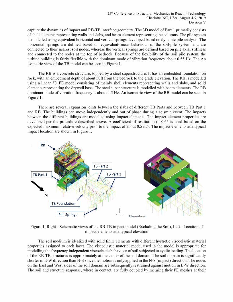
The soil medium is idealized with solid finite elements with different hystretic viscoelastic material
properties assigned to each layer. The viscoelastic material model used in the model is appropriate for modelling the frequency independent viscoelastic behaviour of soil subjected to cyclic loading. The location of the RB-TB structures is approximately at the center of the soil domain. The soil domain is significantly shorter in E-W direction than N-S since the motion is only applied in the N-S (impact) direction. The nodes on the East and West sides of the soil domain are subsequently restrained against motion in E-W direction. The soil and structure response, where in contact, are fully coupled by merging their FE meshes at their
N
25th Conference on Structural Mechanics in Reactor Technology
Charlotte, NC, USA, August 4-9, 2019 Division V
interface. The non-reflecting boundary conditions of the soil domain are modelled using Lysmer (1969) approach. An isometric view of the soil FE model can be seen in Figure 2.
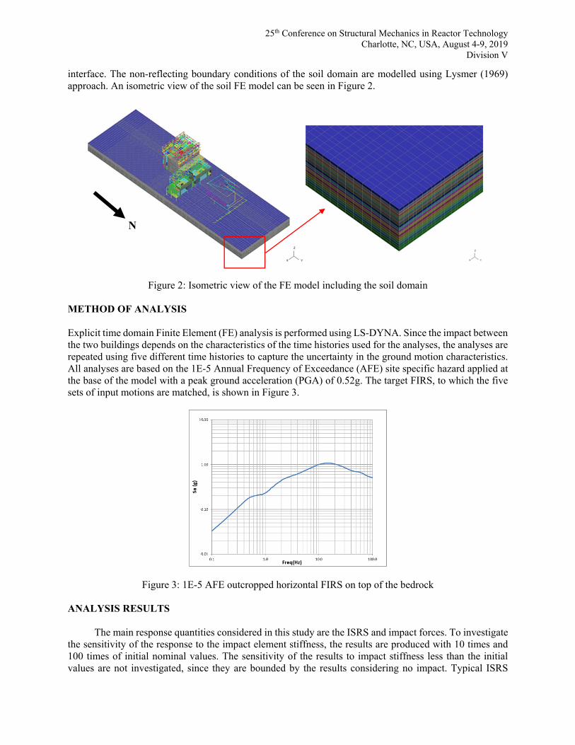
Figure 2: Isometric view of the FE model including the soil domain METHOD OF ANALYSIS Explicit time domain Finite Element (FE) analysis is performed using LS-DYNA. Since the impact between the two buildings depends on the characteristics of the time histories used for the analyses, the analyses are repeated using five different time histories to capture the uncertainty in the ground motion characteristics. All analyses are based on the 1E-5 Annual Frequency of Exceedance (AFE) site specific hazard applied at the base of the model with a peak ground acceleration (PGA) of 0.52g. The target FIRS, to which the five sets of input motions are matched, is shown in Figure 3.
Figure 3: 1E-5 AFE outcropped horizontal FIRS on top of the bedrock ANALYSIS RESULTS
The main response quantities considered in this study are the ISRS and impact forces. To investigate
the sensitivity of the response to the impact element stiffness, the results are produced with 10 times and 100 times of initial nominal values. The sensitivity of the results to impact stiffness less than the initial values are not investigated, since they are bounded by the results considering no impact. Typical ISRS
N
25th Conference on Structural Mechanics in Reactor Technology
Charlotte, NC, USA, August 4-9, 2019 Division V
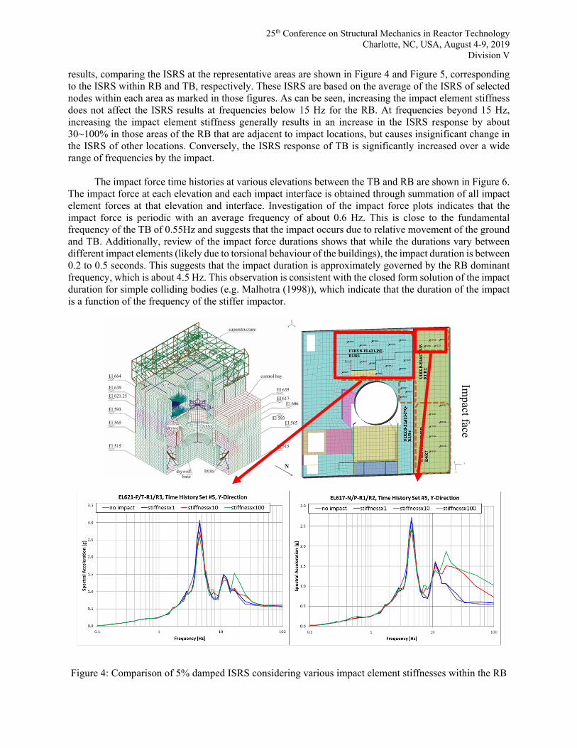
results, comparing the ISRS at the representative areas are shown in Figure 4 and Figure 5, corresponding to the ISRS within RB and TB, respectively. These ISRS are based on the average of the ISRS of selected nodes within each area as marked in those figures. As can be seen, increasing the impact element stiffness does not affect the ISRS results at frequencies below 15 Hz for the RB. At frequencies beyond 15 Hz, increasing the impact element stiffness generally results in an increase in the ISRS response by about 30~100% in those areas of the RB that are adjacent to impact locations, but causes insignificant change in the ISRS of other locations. Conversely, the ISRS response of TB is significantly increased over a wide range of frequencies by the impact.
The impact force time histories at various elevations between the TB and RB are shown in Figure 6. The impact force at each elevation and each impact interface is obtained through summation of all impact element forces at that elevation and interface. Investigation of the impact force plots indicates that the impact force is periodic with an average frequency of about 0.6 Hz. This is close to the fundamental frequency of the TB of 0.55Hz and suggests that the impact occurs due to relative movement of the ground and TB. Additionally, review of the impact force durations shows that while the durations vary between different impact elements (likely due to torsional behaviour of the buildings), the impact duration is between 0.2 to 0.5 seconds. This suggests that the impact duration is approximately governed by the RB dominant frequency, which is about 4.5 Hz. This observation is consistent with the closed form solution of the impact duration for simple colliding bodies (e.g. Malhotra (1998)), which indicate that the duration of the impact is a function of the frequency of the stiffer impactor.
Figure 4: Comparison of 5% damped ISRS considering various impact element stiffnesses within the RB
Impact face
25th Conference on Structural Mechanics in Reactor Technology
Charlotte, NC, USA, August 4-9, 2019 Division V
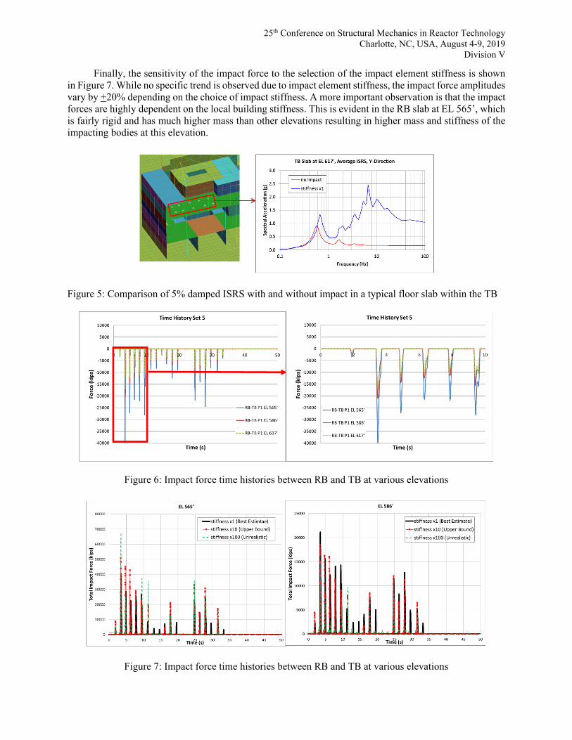
Finally, the sensitivity of the impact force to the selection of the impact element stiffness is shown in Figure 7. While no specific trend is observed due to impact element stiffness, the impact force amplitudes vary by +20% depending on the choice of impact stiffness. A more important observation is that the impact forces are highly dependent on the local building stiffness. This is evident in the RB slab at EL 565’, which is fairly rigid and has much higher mass than other elevations resulting in higher mass and stiffness of the impacting bodies at this elevation.
Figure 5: Comparison of 5% damped ISRS with and without impact in a typical floor slab within the TB
Figure 6: Impact force time histories between RB and TB at various elevations
Figure 7: Impact force time histories between RB and TB at various elevations

25th Conference on Structural Mechanics in Reactor Technology
Charlotte, NC, USA, August 4-9, 2019 Division V
Fragility evaluation of the RB wall subjected to TB impact There is one wall in the RB that is susceptible to TB impact between the EL 565’ and EL 593’ because the TB slab at this region hits the RB wall (slab to wall impact) as opposed to the rest of the impact locations which are slab-to-slab; slab to slab impacts are not expected to cause significant structural damage due to in-plane rigidity of the slabs. Evaluation of the impact forces and the resulting displacements indicate that the local deformations of the RB wall caused by the TB impact exceed the elastic deformation limit of the wall. Therefore, the impact forces obtained from the impact analysis cannot be used in the fragility evaluations directly, as they are based on the consideration of linear behaviour of the RB shear wall in the FE model. Rather, the wall capacities are calculated in terms of plastic deformation capacities and are compared against the deformation demands from the analyses. The fragility assessment of the RB wall is based on the conservative deterministic failure margin (CDFM) approach [EPRI (2013)] using the wall High-Confidence-of-Low-Probability-of-Failure (HCLPF) capacity and is summarized in the following steps:
Step 1 – Determination of the governing mode of failure: Out-of-plane flexure, out-of-plane shear, and stability are considered as possible modes of failure of the subject shear wall. These failure modes are evaluated to determine the governing mode of failure to be considered in fragility evaluation. The expected sequence of degradation and the resulting shift in the load path as the wall goes through damage during the impact are considered in this failure mode evaluation as shown in Figure 8. It is found that the governing mode of failure is shear. The effect of co-existing in-plane shear in reducing the out-of-plane shear capacity is properly considered by using elliptical formula [Hanasapinyo et al. (2003)]. Figure 8 shows a summary of the failure mode evaluation and screening process.
Figure 8: RB wall failure mode evaluation and screening process

25th Conference on Structural Mechanics in Reactor Technology
Charlotte, NC, USA, August 4-9, 2019 Division V
Step 2 – Evaluation of the HCLPF capacity: The step involves scaling of the deflection demand of
the RB wall at the 1E-5 AFE hazard to the HCLPF hazard. This scaling is nonlinear due to a) nonlinear nature of the impact and b) nonlinear behaviour of the TB foundation system. To estimate the RB wall deformation at higher hazards, first, the maximum deflection of the RB wall is extracted from the analyses performed at 1E-5 AFE hazard with the five ground input motions, and subsequently averaged to estimate the conservative (80th percentile) deformation demand. Then, the scale factor for the spectral velocity of TB at a higher hazard (close to HCLPF) is obtained and used to scale up the impact force at higher hazard by considering the change in the momentum of RB-TB system. This approach assumes that the deformation and impact force are linearly correlated. The effect of the reduction in natural frequency of the TB due to foundation nonlinearity and its effect on the spectral velocity is accounted for by approximating the secant stiffness of the TB foundation system using the nonlinear foundation force displacement relationship.
Following the above procedure, the HCLPF acceleration capacity is estimated as 0.97g, based on which, the fragility functions are derived. As the RB global fragility credits the subject shear wall capacity, the global RB fragility would also need to be updated to account for the local wall impact fragility; i.e. if the shear wall impact fragility is less than the RB global fragility, the shear wall would need to be removed from the global RB lateral force resisting system and the RB global capacity and the resulting fragility would then need to be updated. The details of this evaluation are not in the scope of this paper.
CONCLUSIONS This paper investigated the effects of seismic impact between two structures with different flexibilities, namely a TB impacting the RB due to seismic motion at beyond-design-basis-hazard level. The results show that the effect of the impact on the ISRS results in the stiffer structure (i.e., the RB) is negligible while it significantly increases the response of the more flexible structure (i.e., TB). The results also show that impact forces are highly dependent on the local rigidity of the impact zones, and the impact forces at the locations where the structure is more rigid are significantly higher. A sensitivity study was performed to investigate the effect of impact element stiffness on the result, which showed that the results and conclusions are not considerably affected by the choice of impact element stiffness. The fragility of the RB wall subjected to impact was also evaluated. It was shown that the failure is governed by the out of plane shear capacity of the wall. A simple procedure was developed to estimate the RB wall deformation caused by impact at hazard levels different than the hazard level used in the impact analyses, in order to account for the nonlinear effects caused by TB foundation system softening at higher hazards in the wall deflection margin.
The approach presented in this paper provides a framework for computational analysis of impact in NPPs, for the cases where the impact is expected to be significant, and simplistic approximation of impact effects (e.g. assuming the impact to automatically cause failure regardless of its significance) is not desired. Rigorous analysis using case-specific considerations and details is a preferred approach in these cases, to investigate the effects of building impact with confidence. REFERENCES
Lysmer, J., Kuhlemeyer, L. (1969). “Finite Dynamic Model for Infinite Media,” Journal of the Engineering
Mechanics Division, Proceedings of the American Society of Civil Engineers, 95(4) 859-878 Anagnostopoulos, S.A. (1988). “Pounding of Buildings in Series during Earthquakes,” Earthquake
Engineering and Structural Dynamics, 16 443-456. Malhotra, P. K. (1998). “Dynamics of seismic pounding at expansion joints of concrete bridges,” Journal
of Engineering Mechanics (ASCE), 124 794– 802

25th Conference on Structural Mechanics in Reactor Technology
Charlotte, NC, USA, August 4-9, 2019 Division V
Chau, K. T., Wei, X. X. (2001). “Pounding of structures modelled as non-linear impacts of two oscillators,” Earthquake Engineering & Structural Dynamics, 30 633-651.
Electrical Power Research Institute (EPRI), (2013), EPRI 1025287 Final Report: Seismic Evaluation Guidance - Screening, Prioritization and Implementation details (SPID) for the Resolution of Fukushima Near-Term Task Force Recommendation 2.1: Seismic.
Goldsmith, W. (1960). Impact: the theory and physical behaviour of colliding solids, Edward Arnold Publishers Ltd., Lindon, UK.
Hansapinyo, H., Maekawa, K., and Chaisomphob, T. (2003), “Behavior of Reinforced Concrete Beams Subjected to Bi-Axial Shear,” J. Materials, Conc. Struct. Pavements, JSCE, 725(58) 321-331.
Jankowski, R. (2004). “Nonlinear Modelling of Earthquake Induced Pounding of Buildings,” Mechanics of the 21st Century-ICTAM04 Proceedings, Warsaw, Poland.
Jankowski, R. (2005). “Impact force spectrum for damage assessment of earthquake-induced structural pounding,” Key Engineering Materials, 293–294 711-718.
Jankowski, R. (2006). “Analytical expression between the impact damping ratio and the coefficient of restitution in the non-linear viscoelastic model of structural pounding,” Earthquake Engineering and Structural Dynamics, 35 517–524.
Muthukumar, S., DesRoches, R. (2006). “A Hertz contact model with non-linear damping for pounding simulation,” Earthquake Engineering & Structural Dynamics, 35 811–828.
Jankowski, R. (2007), Theoretical and Experimental Assessment of Parameters for the Non-linear Viscoelastic Model of Structural Pounding, Theoretical and Applied Mechanics, 45(4) 931-942.
Kasai, K., Jeng, V., and Maison, B. F. (1990). “The Significant Effects of Pounding-Induced Accelerations on Building Appurtenances,” ATC-29 Seminar and Workshop on Seismic Design and Performance of Equipment and Nonstructural Elements in Buildings and Industrial Structures, Irvine, California, USA.
Kasai, K., Jeng, V., Patel, P. C., and Munshi, J. A. (1992), Seismic Pounding Effects-Survey and Analysis, 10th World Conference on Earthquake Engineering, Balkema, Rotterdam. Pages 3893-3896.
Pantelides, C.P., Ma, X. (1998). “Linear and nonlinear pounding of structural systems,” Computers & Structures 66(1) 79-92.
Wolf, J. P., and Skrikerud, P. E. (1979). “Mutual Pounding of Adjacent Structures During Earthquakes,” SMiRT 5 Transactions, Berlin, Germany.
Ye, K., Li, L., Zhu, H. (2009). “A note on the Hertz contact model with nonlinear damping for pounding simulation,” Earthquake Engineering & Structural Dynamics, 38 1135-1142.