(a) Butt joint (b) Corner joint (c) T joint (d) Lap joint ... · Manufacturing Processes for...
44
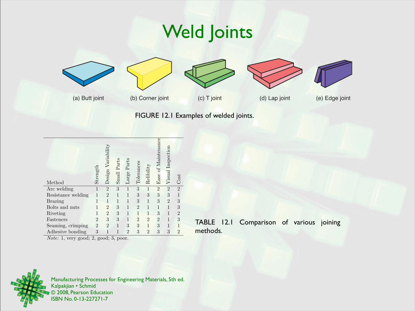
Manufacturing Processes for Engineering Materials, 5th ed. Kalpakjian • Schmid © 2008, Pearson Education ISBN No. 0-13-227271-7 Weld Joints FIGURE 12.1 Examples of welded joints. (a) Butt joint (b) Corner joint (c) T joint (d) Lap joint (e) Edge joint Method Strength Design Variability Small Parts Large Parts Tolerances Relibility Ease of Maintenance Visual Inspection Cost Arc welding 1 2 3 1 3 1 2 2 2 Resistance welding 1 2 1 1 3 3 3 3 1 Brazing 1 1 1 1 3 1 3 2 3 Bolts and nuts 1 2 3 1 2 1 1 1 3 Riveting 1 2 3 1 1 1 3 1 2 Fasteners 2 3 3 1 2 2 2 1 3 Seaming, crimping 2 2 1 3 3 1 3 1 1 Adhesive bonding 3 1 1 2 3 2 3 3 2 Note: 1, very good; 2, good; 3, poor. TABLE 12.1 Comparison of various joining methods.
-
Upload
hoangtuyen -
Category
Documents
-
view
228 -
download
3
Transcript of (a) Butt joint (b) Corner joint (c) T joint (d) Lap joint ... · Manufacturing Processes for...
Manufacturing Processes for Engineering Materials, 5th ed. Kalpakjian • Schmid© 2008, Pearson EducationISBN No. 0-13-227271-7
Weld Joints
FIGURE 12.1 Examples of welded joints.
(a) Butt joint (b) Corner joint (c) T joint (d) Lap joint (e) Edge joint
Method Stre
ngth
Des
ign
Var
iabi
lity
Smal
lPar
ts
Larg
ePar
ts
Tole
ranc
es
Rel
ibili
ty
Eas
eof
Mai
nten
ance
Vis
ualI
nspe
ctio
n
Cos
t
Arc welding 1 2 3 1 3 1 2 2 2Resistance welding 1 2 1 1 3 3 3 3 1Brazing 1 1 1 1 3 1 3 2 3Bolts and nuts 1 2 3 1 2 1 1 1 3Riveting 1 2 3 1 1 1 3 1 2Fasteners 2 3 3 1 2 2 2 1 3Seaming, crimping 2 2 1 3 3 1 3 1 1Adhesive bonding 3 1 1 2 3 2 3 3 2Note: 1, very good; 2, good; 3, poor.
TABLE 12.1 Comparison of various joining methods.
Manufacturing Processes for Engineering Materials, 5th ed. Kalpakjian • Schmid© 2008, Pearson EducationISBN No. 0-13-227271-7
General Summary
Joining Skill Level Welding Current Distor- Cost ofProcess Operation Advantage Required Position Type tion! EquipmentShieldedmetal arc
Manual Portableand flexible
High All ac, dc 1 to 2 Low
Submergedarc
Automatic High deposi-tion
Low tomedium
Flat andhorizontal
ac, dc 1 to 2 Medium
Gas metalarc
Semiautomaticor automatic
Works withmost metals
Low tohigh
All dc 2 to 3 Medium tohigh
Gas tung-sten arc
Manual orautomatic
Works withmost metals
Low tohigh
All ac, dc 2 to 3 Medium
Flux-coredarc
Semiautomaticor automatic
High deposi-tion
Low tohigh
All dc 1 to 3 Medium
Oxyfuel Manual Portableand flexible
High All – 2 to 4 Low
Electronbeam, laserbeam
Semiautomaticor automatic
Works withmost metals
Medium tohigh
All – 3 to 5 High
! 1, highest; 5, lowest
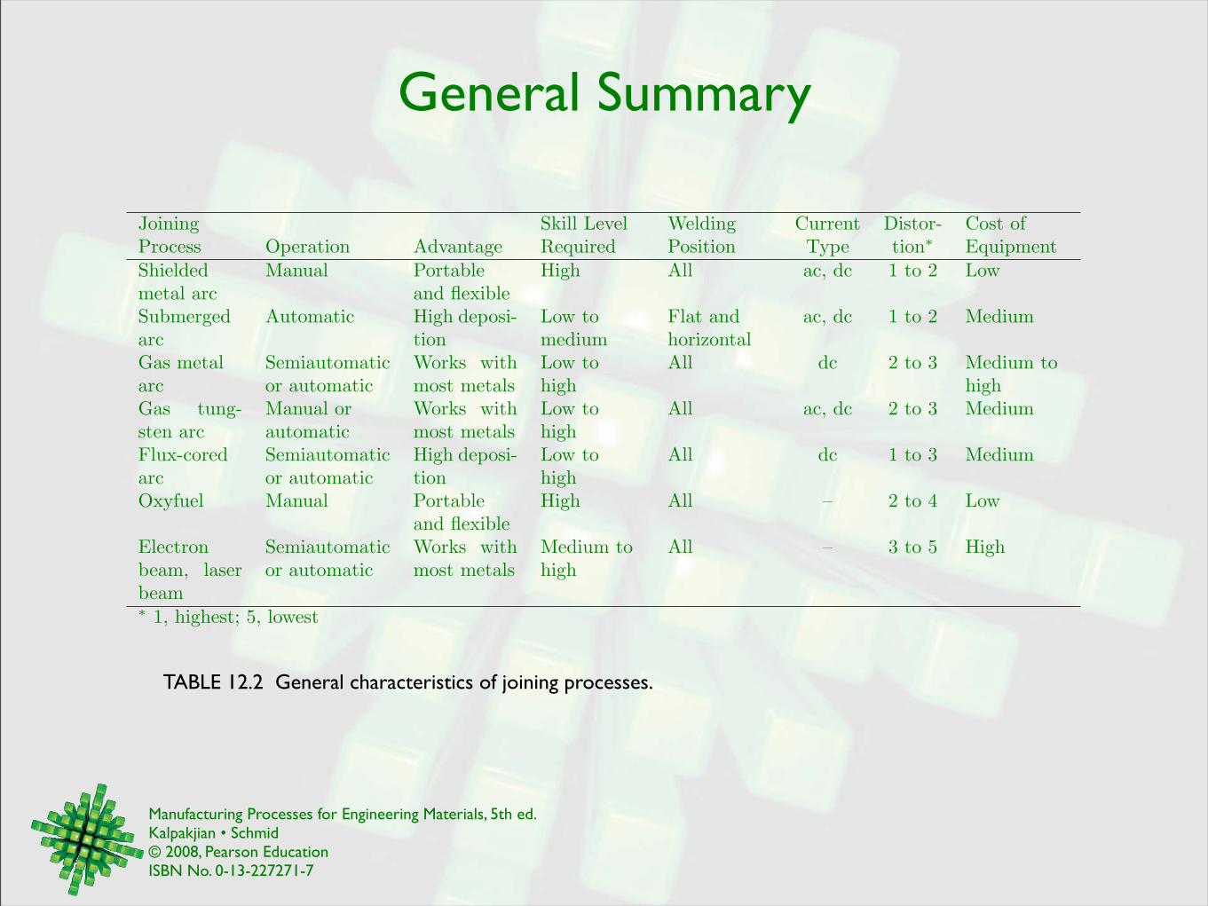
TABLE 12.2 General characteristics of joining processes.
Manufacturing Processes for Engineering Materials, 5th ed. Kalpakjian • Schmid© 2008, Pearson EducationISBN No. 0-13-227271-7
Oxyfuel Gas Welding
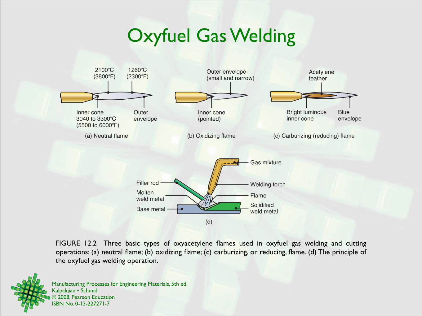
FIGURE 12.2 Three basic types of oxyacetylene flames used in oxyfuel gas welding and cutting operations: (a) neutral flame; (b) oxidizing flame; (c) carburizing, or reducing, flame. (d) The principle of the oxyfuel gas welding operation.
(a) Neutral flame (b) Oxidizing flame (c) Carburizing (reducing) flame
2100°C(3800°F)
1260°C(2300°F)
Inner cone3040 to 3300°C(5500 to 6000°F)
Outerenvelope
Outer envelope(small and narrow)
Inner cone(pointed)
Acetylenefeather
Bright luminousinner cone
Blueenvelope
(d)
Gas mixture
Welding torch
Flame
Solidifiedweld metal
Moltenweld metal
Filler rod
Base metal
Manufacturing Processes for Engineering Materials, 5th ed. Kalpakjian • Schmid© 2008, Pearson EducationISBN No. 0-13-227271-7
Pressure Gas Welding
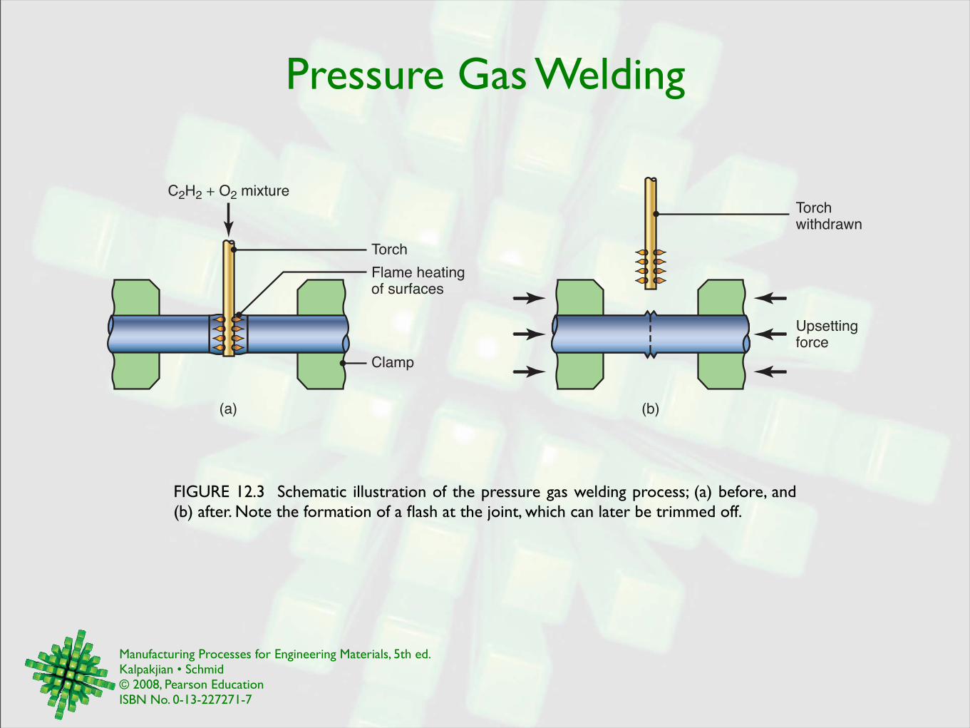
FIGURE 12.3 Schematic illustration of the pressure gas welding process; (a) before, and (b) after. Note the formation of a flash at the joint, which can later be trimmed off.
C2H2 + O2 mixture
Torch
Flame heatingof surfaces
Clamp
Upsettingforce
Torchwithdrawn
(a) (b)
Manufacturing Processes for Engineering Materials, 5th ed. Kalpakjian • Schmid© 2008, Pearson EducationISBN No. 0-13-227271-7
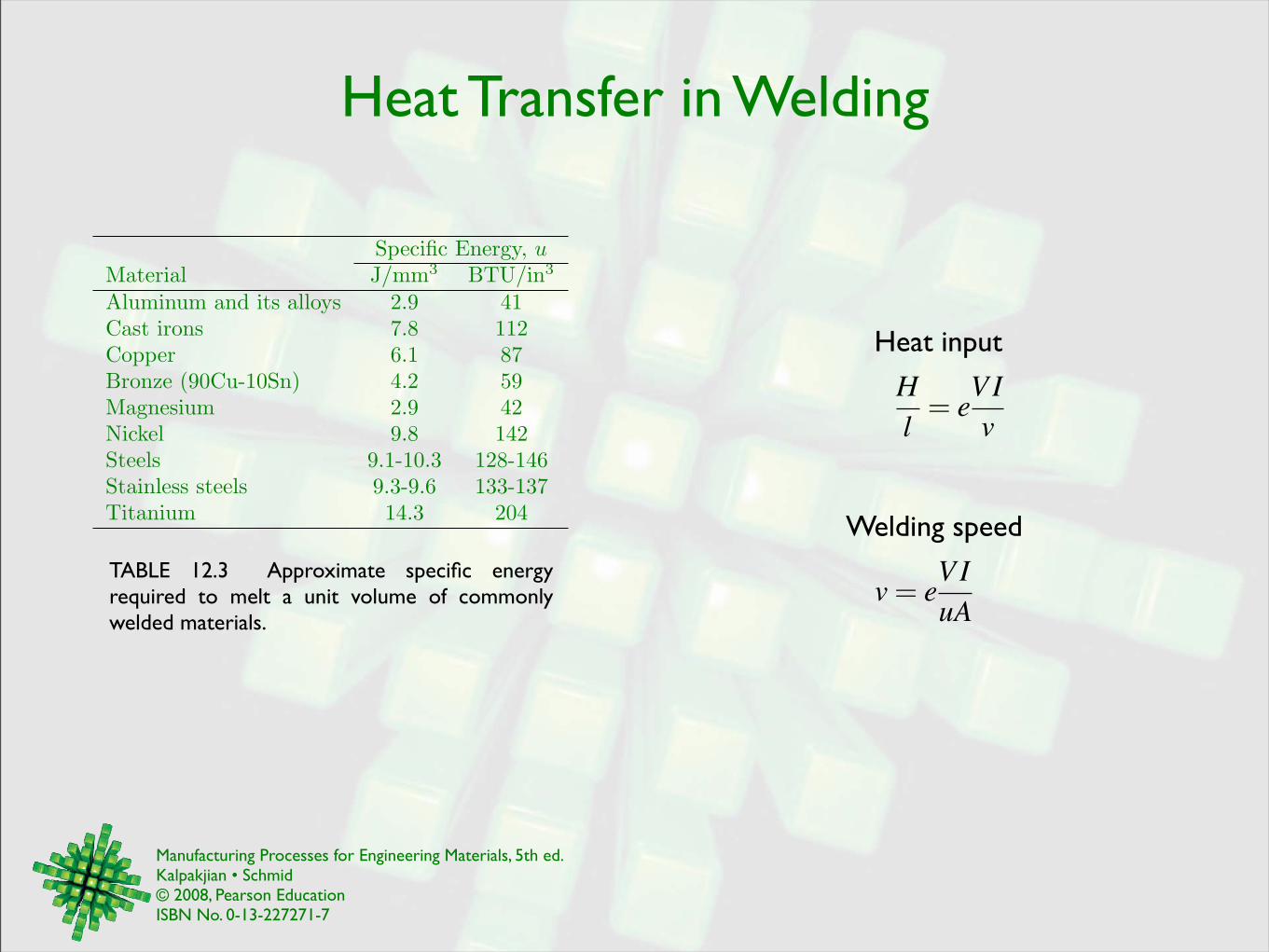
Heat Transfer in Welding
Specific Energy, uMaterial J/mm3 BTU/in3
Aluminum and its alloys 2.9 41Cast irons 7.8 112Copper 6.1 87Bronze (90Cu-10Sn) 4.2 59Magnesium 2.9 42Nickel 9.8 142Steels 9.1-10.3 128-146Stainless steels 9.3-9.6 133-137Titanium 14.3 204
TABLE 12.3 Approximate specific energy required to melt a unit volume of commonly welded materials.
Heat input
Welding speed
Hl
= eVIv
v= eVIuA
Manufacturing Processes for Engineering Materials, 5th ed. Kalpakjian • Schmid© 2008, Pearson EducationISBN No. 0-13-227271-7
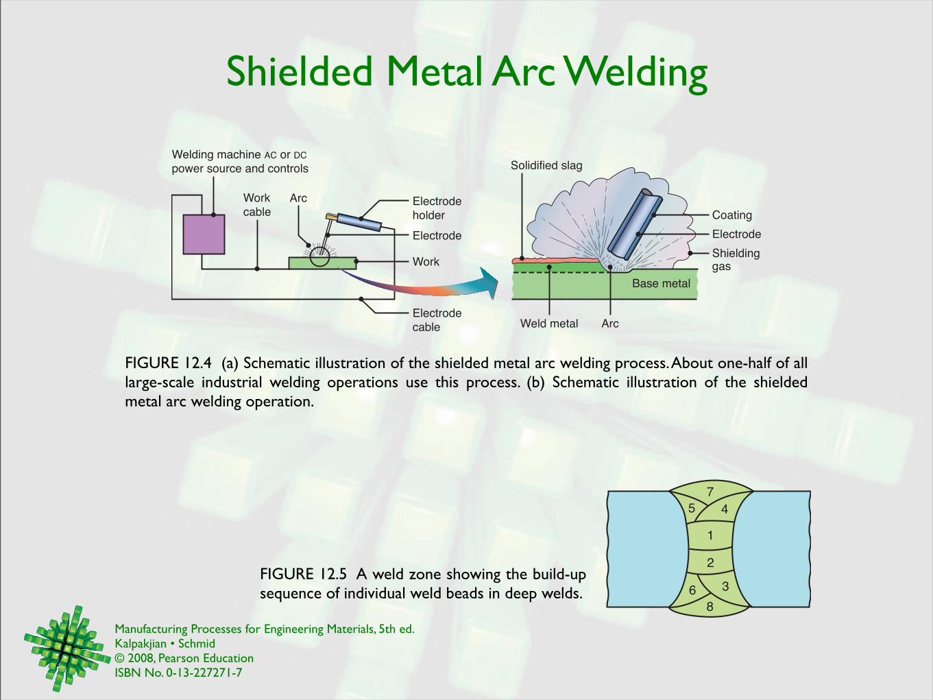
Shielded Metal Arc Welding
FIGURE 12.4 (a) Schematic illustration of the shielded metal arc welding process. About one-half of all large-scale industrial welding operations use this process. (b) Schematic illustration of the shielded metal arc welding operation.
Welding machine AC or DC
power source and controls
Electrode
Electrode
holder
Arc
Solidified slag
Coating
Electrode
Shieldinggas
Base metal
ArcWeld metal
Work
Work
cable
Electrode
cable
FIGURE 12.5 A weld zone showing the build-up sequence of individual weld beads in deep welds.
7
1
2
8
5 4
6 3
Manufacturing Processes for Engineering Materials, 5th ed. Kalpakjian • Schmid© 2008, Pearson EducationISBN No. 0-13-227271-7
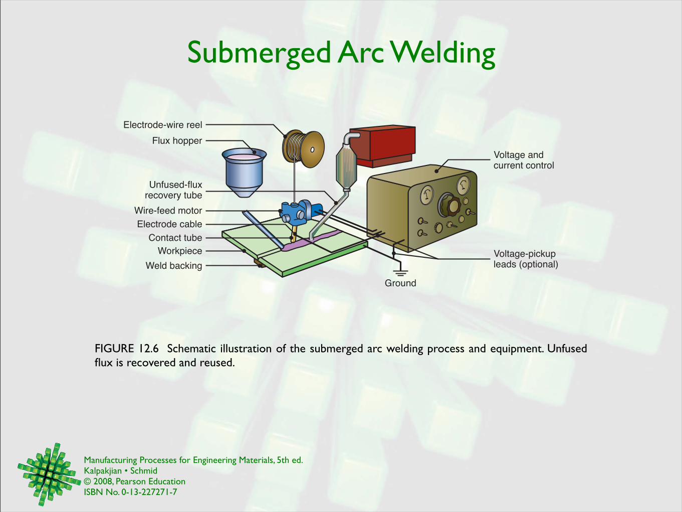
Submerged Arc Welding
FIGURE 12.6 Schematic illustration of the submerged arc welding process and equipment. Unfused flux is recovered and reused.
Electrode-wire reel
Electrode cable
Voltage andcurrent control
Voltage-pickupleads (optional)
Ground
Wire-feed motor
Unfused-fluxrecovery tube
Flux hopper
Contact tube
Workpiece
Weld backing
Manufacturing Processes for Engineering Materials, 5th ed. Kalpakjian • Schmid© 2008, Pearson EducationISBN No. 0-13-227271-7
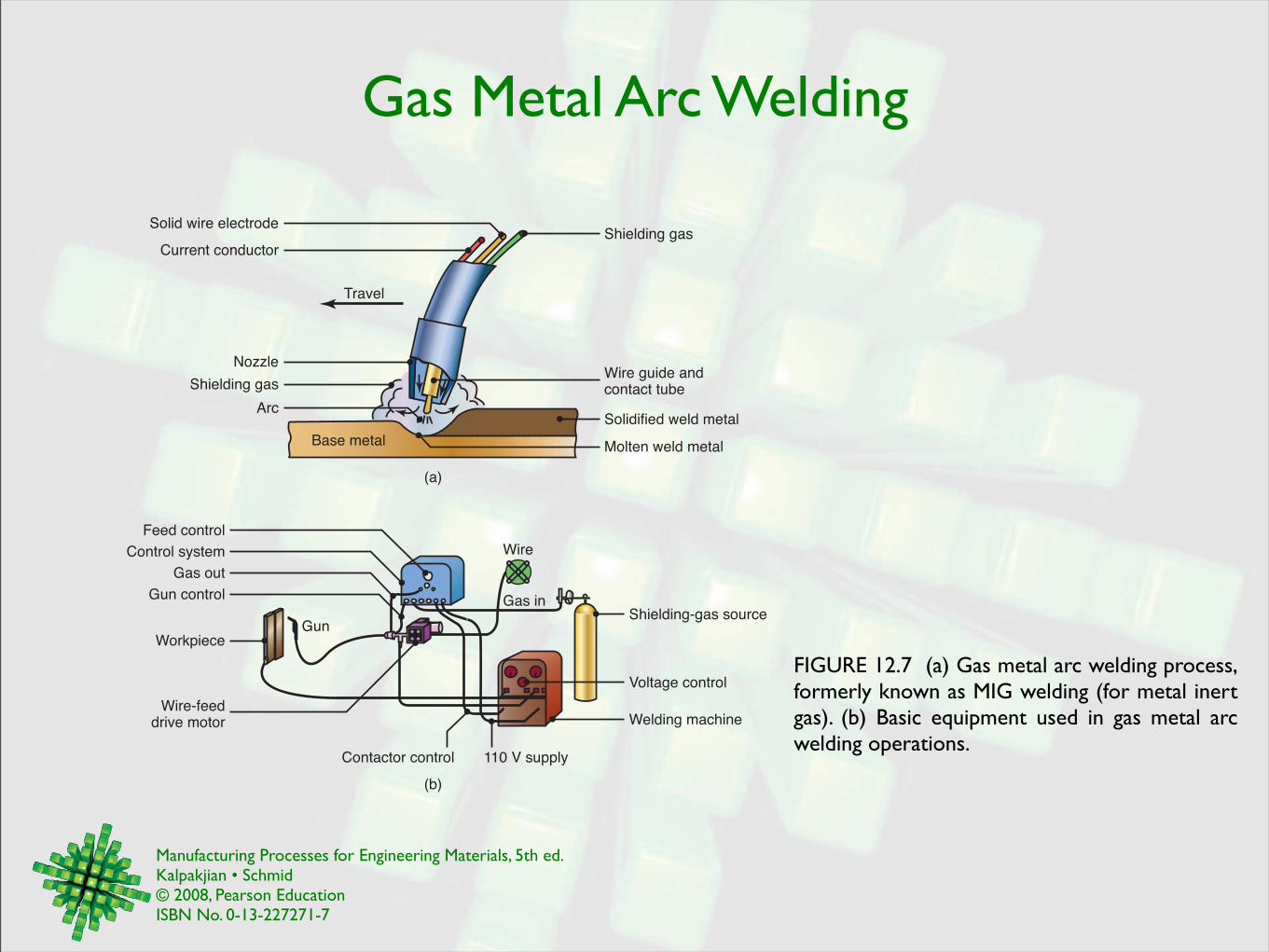
Gas Metal Arc Welding
FIGURE 12.7 (a) Gas metal arc welding process, formerly known as MIG welding (for metal inert gas). (b) Basic equipment used in gas metal arc welding operations.
Shielding gas
Nozzle
Travel
Arc
Base metal Molten weld metal
Solidified weld metal
Wire guide andcontact tube
Shielding gasSolid wire electrode
Current conductor
WorkpieceGun
Feed control
Control system
Gas out
Gun control Gas in
Wire
Shielding-gas source
Wire-feeddrive motor
110 V supply
Voltage control
Contactor control
(a)
(b)
Welding machine
Manufacturing Processes for Engineering Materials, 5th ed. Kalpakjian • Schmid© 2008, Pearson EducationISBN No. 0-13-227271-7
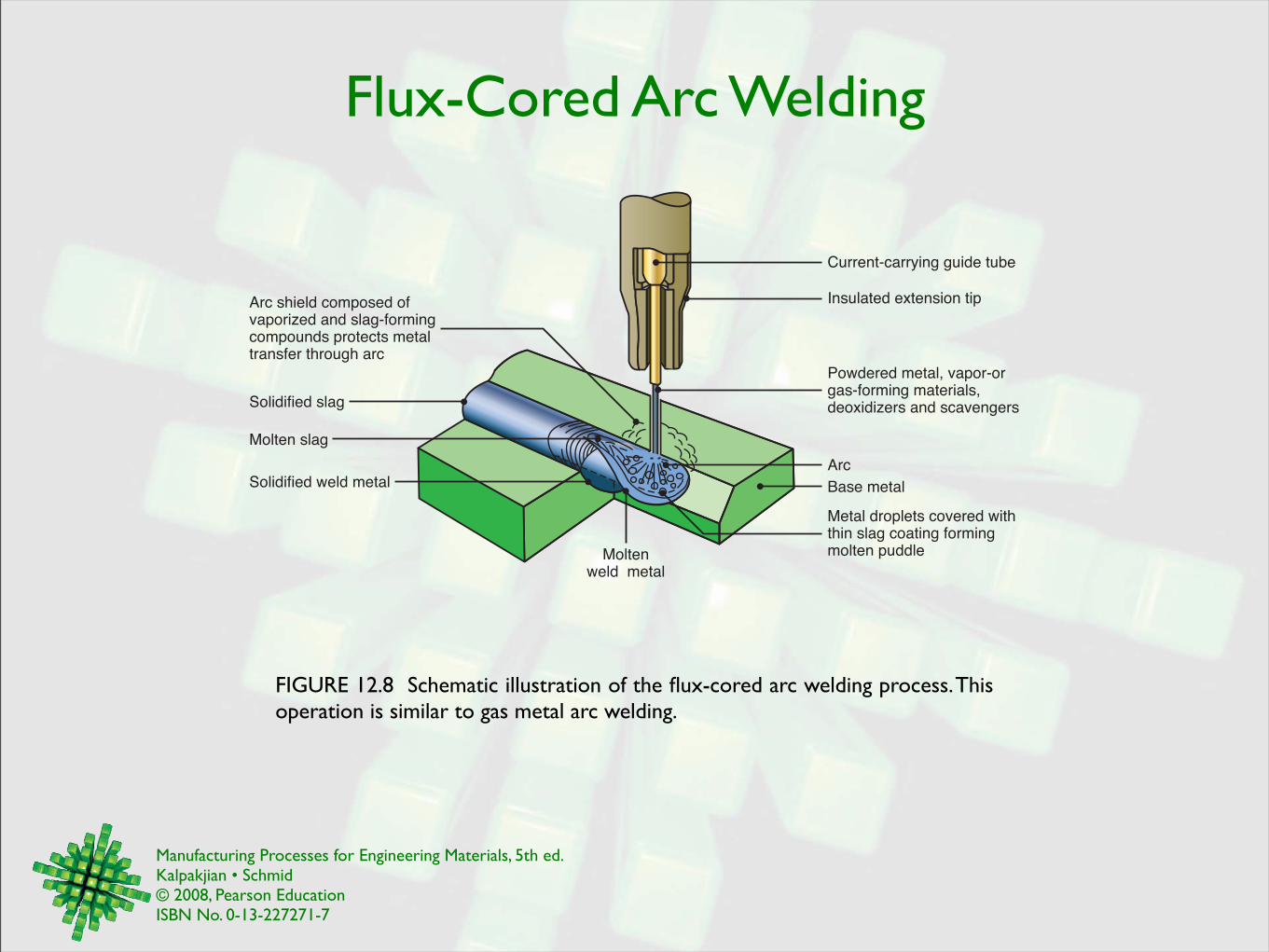
Flux-Cored Arc Welding
FIGURE 12.8 Schematic illustration of the flux-cored arc welding process. This operation is similar to gas metal arc welding.
Metal droplets covered withthin slag coating formingmolten puddle
Powdered metal, vapor-orgas-forming materials,deoxidizers and scavengers
Insulated extension tip
Current-carrying guide tube
Arc
Base metal
Arc shield composed ofvaporized and slag-formingcompounds protects metaltransfer through arc
Solidified slag
Molten slag
Solidified weld metal
Moltenweld metal
Manufacturing Processes for Engineering Materials, 5th ed. Kalpakjian • Schmid© 2008, Pearson EducationISBN No. 0-13-227271-7
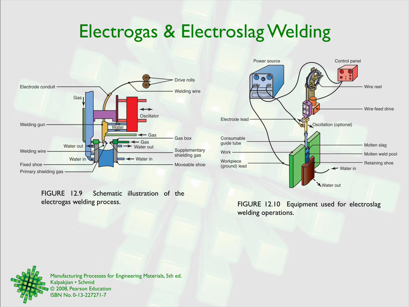
Electrogas & Electroslag Welding
FIGURE 12.9 Schematic illustration of the electrogas welding process.
Welding wire
Drive rolls
Electrode conduit
Gas
Welding gun
Welding wireWater out
Water in Water in
Water out
Moveable shoeFixed shoe
Primary shielding gas
Supplementaryshielding gas
GasGas box
Water
Gas
Oscillator
FIGURE 12.10 Equipment used for electroslag welding operations.
Control panel
Wire reel
Wire-feed drive
Oscillation (optional)
Molten slag
Molten weld pool
Retaining shoe
Water in
Consumableguide tube
Water out
Work
Workpiece(ground) lead
Electrode lead
Power source
Manufacturing Processes for Engineering Materials, 5th ed. Kalpakjian • Schmid© 2008, Pearson EducationISBN No. 0-13-227271-7
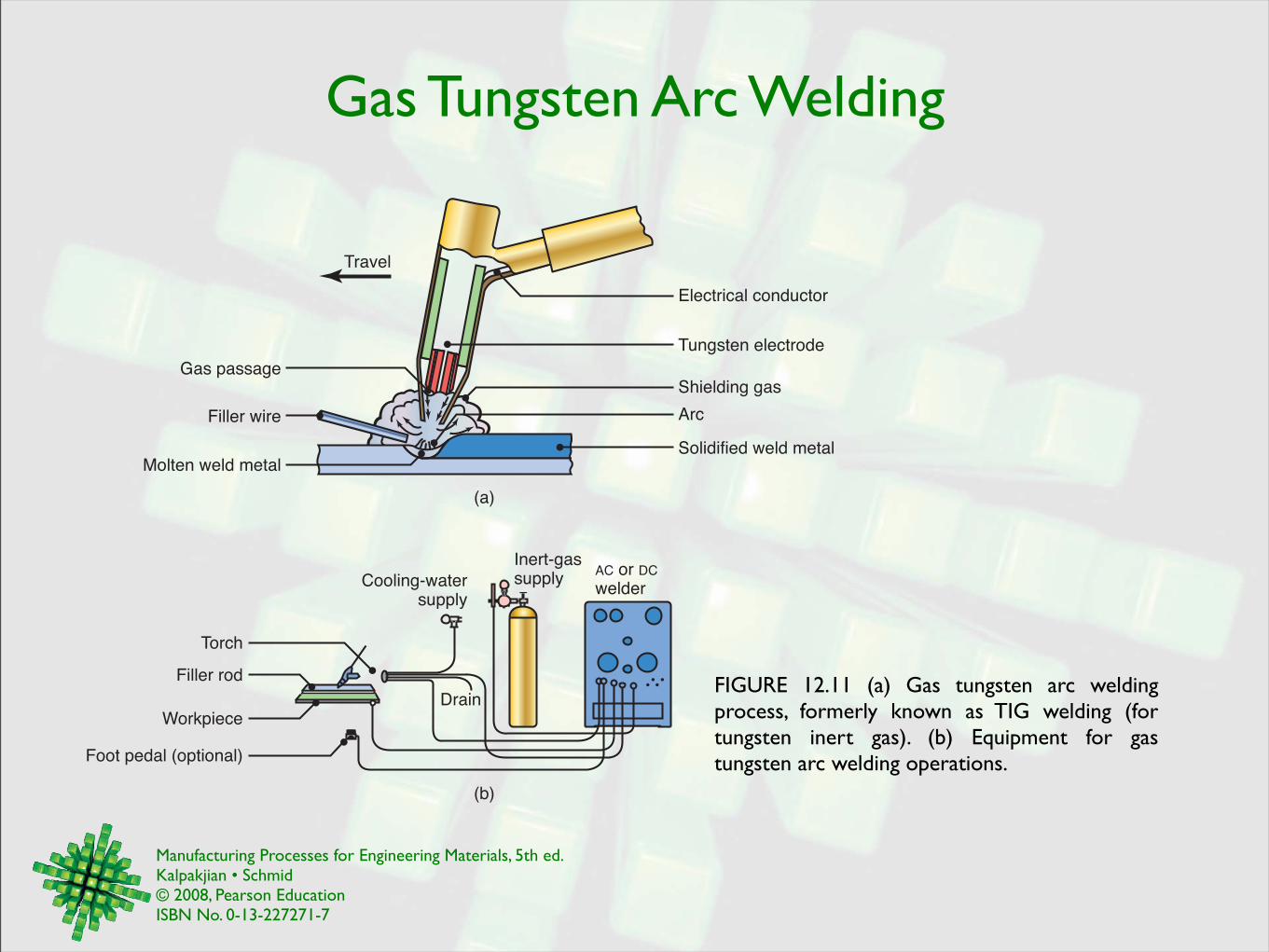
Gas Tungsten Arc Welding
FIGURE 12.11 (a) Gas tungsten arc welding process, formerly known as TIG welding (for tungsten inert gas). (b) Equipment for gas tungsten arc welding operations.
Electrical conductor
Tungsten electrode
Shielding gas
Arc
Travel
Filler wire
Molten weld metal
Gas passage
Filler rod
Cooling-watersupply
Inert-gassupply
Foot pedal (optional)
WorkpieceDrain
AC or DC
welder
(a)
(b)
Solidified weld metal
Torch
Manufacturing Processes for Engineering Materials, 5th ed. Kalpakjian • Schmid© 2008, Pearson EducationISBN No. 0-13-227271-7
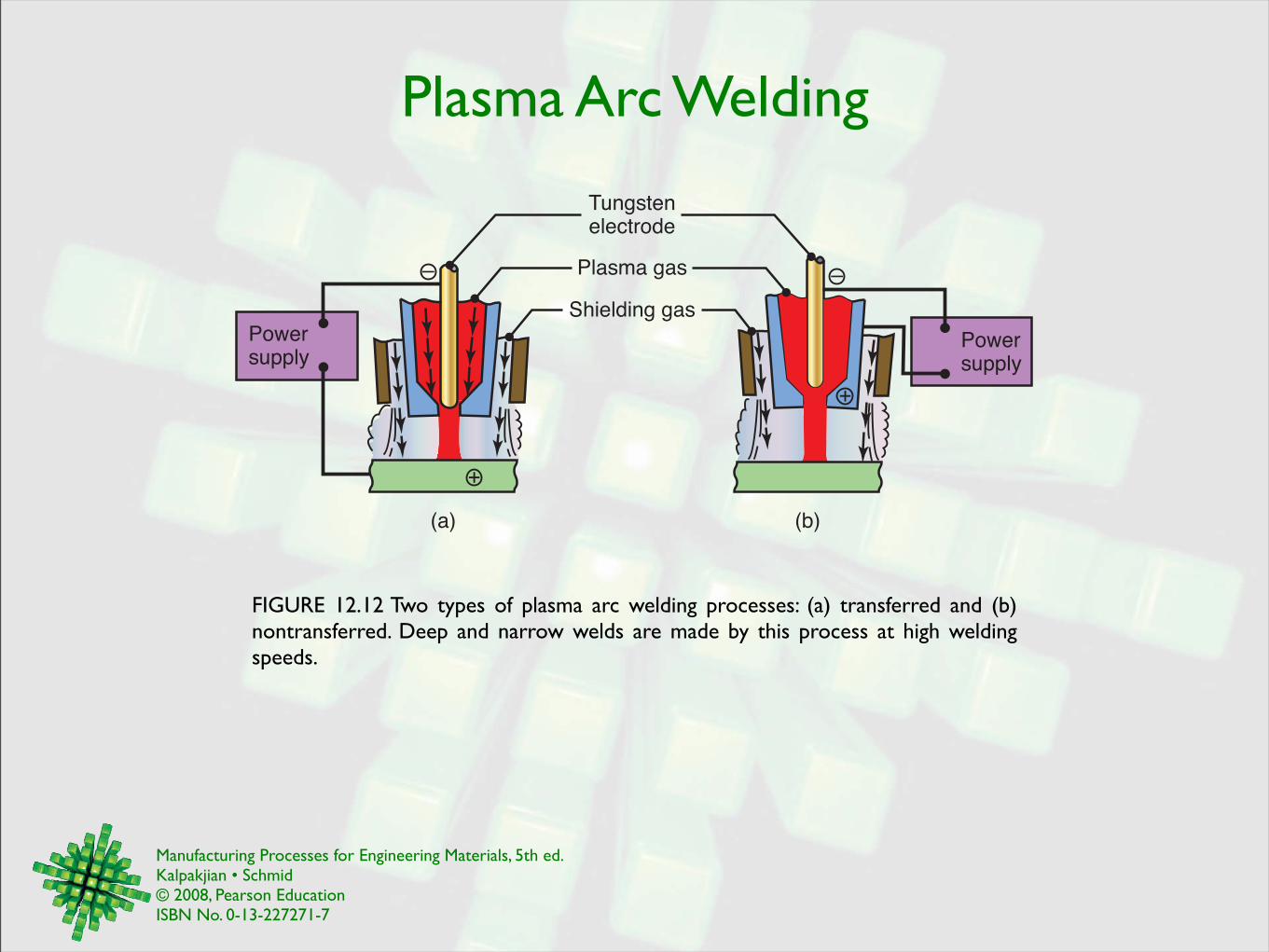
Plasma Arc Welding
FIGURE 12.12 Two types of plasma arc welding processes: (a) transferred and (b) nontransferred. Deep and narrow welds are made by this process at high welding speeds.
Powersupply
Tungstenelectrode
Plasma gas
Shielding gas
(a) (b)
–
Powersupply
–
+
+
Manufacturing Processes for Engineering Materials, 5th ed. Kalpakjian • Schmid© 2008, Pearson EducationISBN No. 0-13-227271-7
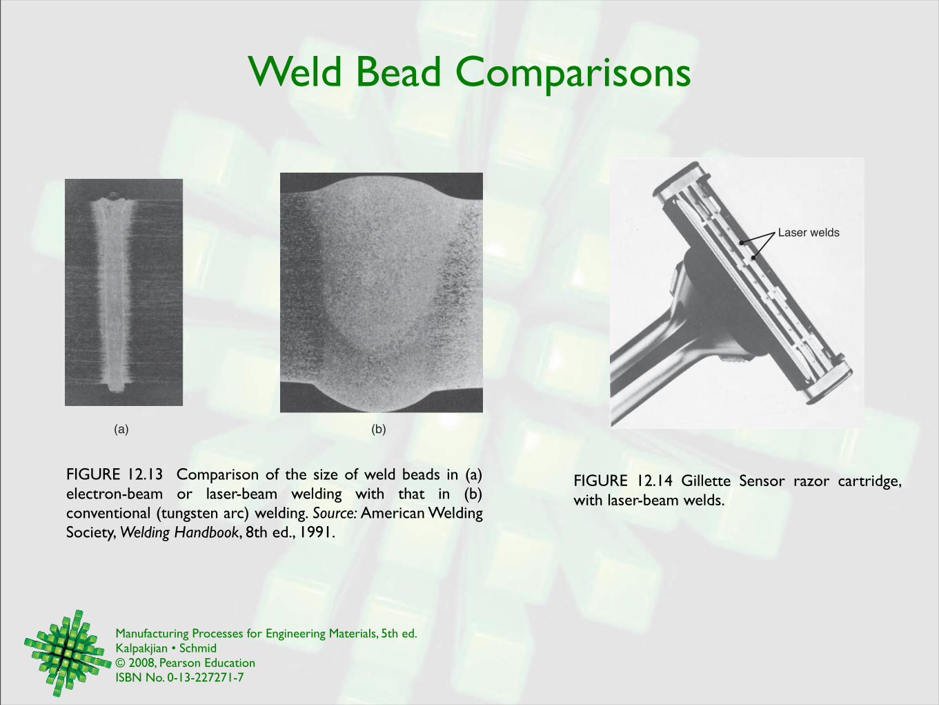
Weld Bead Comparisons
FIGURE 12.13 Comparison of the size of weld beads in (a) electron-beam or laser-beam welding with that in (b) conventional (tungsten arc) welding. Source: American Welding Society, Welding Handbook, 8th ed., 1991.
(a) (b)
FIGURE 12.14 Gillette Sensor razor cartridge, with laser-beam welds.
Laser welds
Manufacturing Processes for Engineering Materials, 5th ed. Kalpakjian • Schmid© 2008, Pearson EducationISBN No. 0-13-227271-7
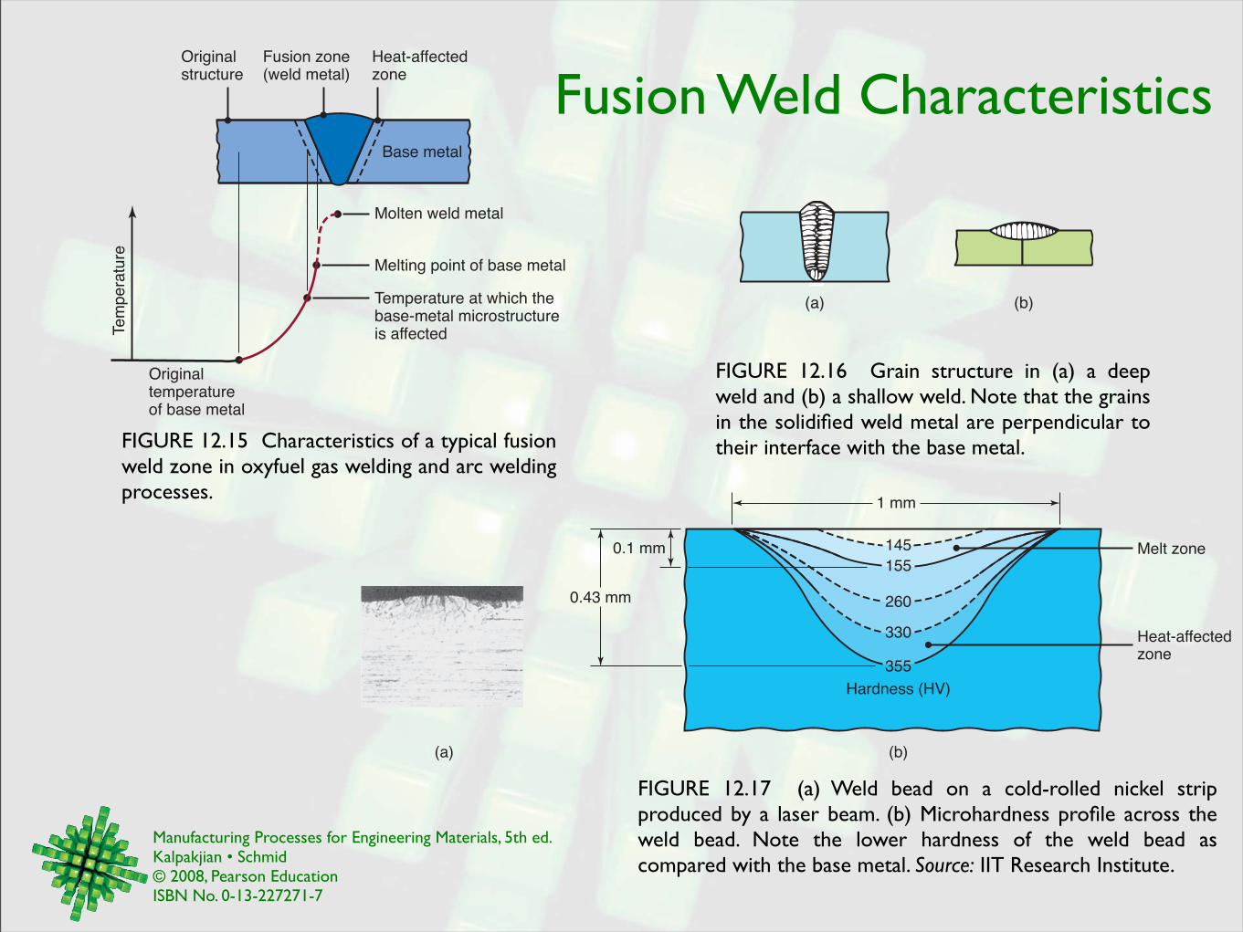
Fusion Weld Characteristics
FIGURE 12.15 Characteristics of a typical fusion weld zone in oxyfuel gas welding and arc welding processes.
Molten weld metal
Melting point of base metal
Temperature at which thebase-metal microstructureis affected
Originaltemperatureof base metal
Te
mp
era
ture
Originalstructure
Heat-affectedzone
Fusion zone(weld metal)
Base metal
FIGURE 12.16 Grain structure in (a) a deep weld and (b) a shallow weld. Note that the grains in the solidified weld metal are perpendicular to their interface with the base metal.
(a) (b)
FIGURE 12.17 (a) Weld bead on a cold-rolled nickel strip produced by a laser beam. (b) Microhardness profile across the weld bead. Note the lower hardness of the weld bead as compared with the base metal. Source: IIT Research Institute.
(a) (b)
145
155
260
330
355
0.1 mm
1 mm
0.43 mm
Hardness (HV)
Heat-affectedzone
Melt zone
Manufacturing Processes for Engineering Materials, 5th ed. Kalpakjian • Schmid© 2008, Pearson EducationISBN No. 0-13-227271-7
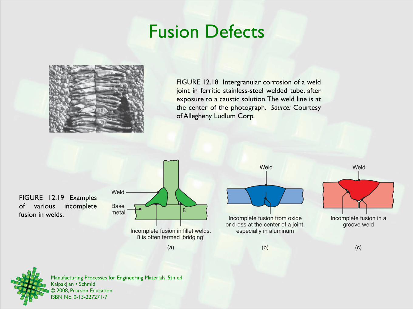
Fusion Defects
FIGURE 12.19 Examples of various incomplete fusion in welds.
FIGURE 12.18 Intergranular corrosion of a weld joint in ferritic stainless-steel welded tube, after exposure to a caustic solution. The weld line is at the center of the photograph. Source: Courtesy of Allegheny Ludlum Corp.
Incomplete fusion in fillet welds.B is often termed !bridging"
B
Weld
Basemetal
(a) (b) (c)
Weld
Incomplete fusion from oxideor dross at the center of a joint,
especially in aluminum
Incomplete fusion in agroove weld
Weld
Manufacturing Processes for Engineering Materials, 5th ed. Kalpakjian • Schmid© 2008, Pearson EducationISBN No. 0-13-227271-7
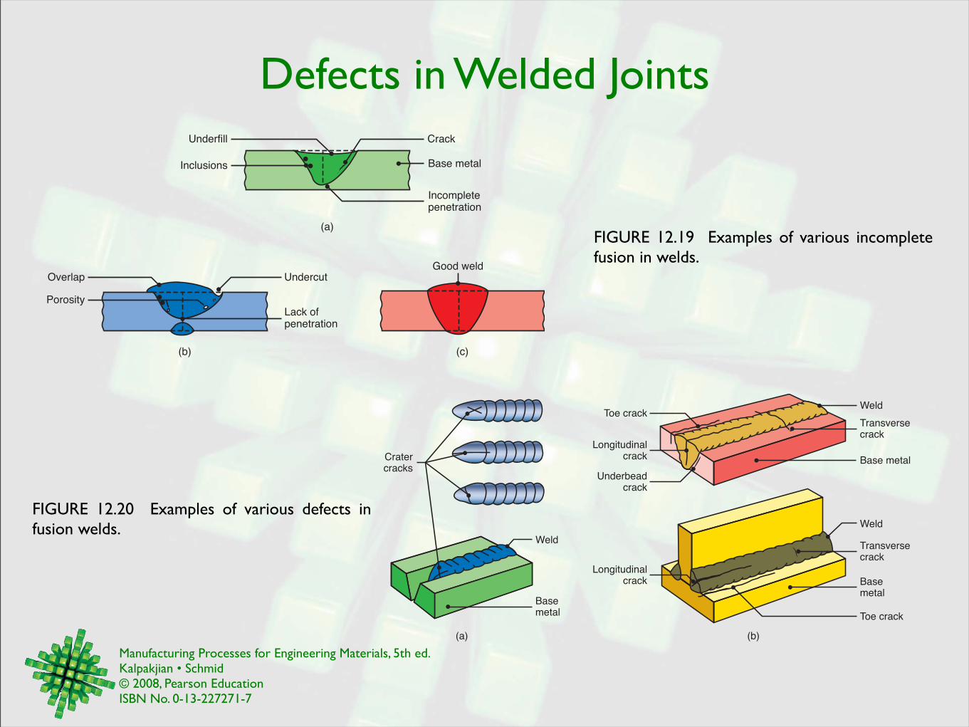
Defects in Welded Joints
FIGURE 12.20 Examples of various defects in fusion welds.
(c)
Good weld
(b)
Lack of penetration
Undercut
Porosity
Overlap
Underfill Crack
Inclusions
(a)
Incomplete penetration
Base metal
FIGURE 12.19 Examples of various incomplete fusion in welds.
Toe crack
Underbeadcrack
Toe crack
Base metal
Weld
Longitudinalcrack
LongitudinalcrackCrater
cracks
Weld
Basemetal
(a) (b)
Transversecrack
Transversecrack
Basemetal
Weld
Manufacturing Processes for Engineering Materials, 5th ed. Kalpakjian • Schmid© 2008, Pearson EducationISBN No. 0-13-227271-7
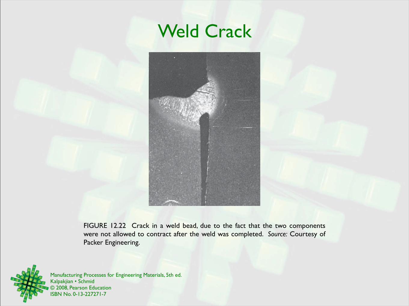
Weld Crack
FIGURE 12.22 Crack in a weld bead, due to the fact that the two components were not allowed to contract after the weld was completed. Source: Courtesy of Packer Engineering.
Manufacturing Processes for Engineering Materials, 5th ed. Kalpakjian • Schmid© 2008, Pearson EducationISBN No. 0-13-227271-7
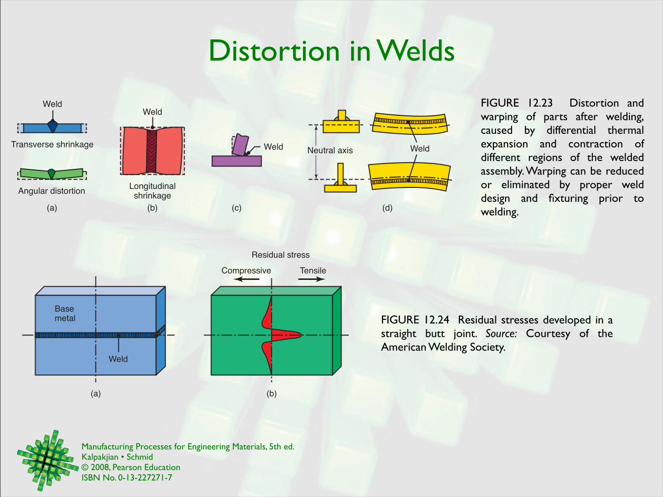
Distortion in Welds
FIGURE 12.24 Residual stresses developed in a straight butt joint. Source: Courtesy of the American Welding Society.
(a) (c) (d)(b)
Transverse shrinkage
Angular distortion
Weld
Longitudinalshrinkage
WeldNeutral axisWeld
Weld FIGURE 12.23 Distortion and warping of parts after welding, caused by differential thermal expansion and contraction of different regions of the welded assembly. Warping can be reduced or eliminated by proper weld design and fixturing prior to welding.
Weld
Basemetal
(b)(a)
Residual stress
Compressive Tensile
Manufacturing Processes for Engineering Materials, 5th ed. Kalpakjian • Schmid© 2008, Pearson EducationISBN No. 0-13-227271-7
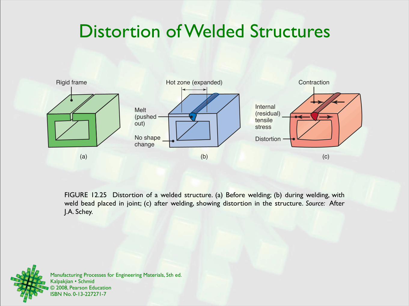
Distortion of Welded Structures
FIGURE 12.25 Distortion of a welded structure. (a) Before welding; (b) during welding, with weld bead placed in joint; (c) after welding, showing distortion in the structure. Source: After J.A. Schey.
Rigid frame Hot zone (expanded)
No shapechange
Melt(pushedout)
Contraction
Internal(residual)tensilestress
Distortion
(a) (b) (c)
Manufacturing Processes for Engineering Materials, 5th ed. Kalpakjian • Schmid© 2008, Pearson EducationISBN No. 0-13-227271-7
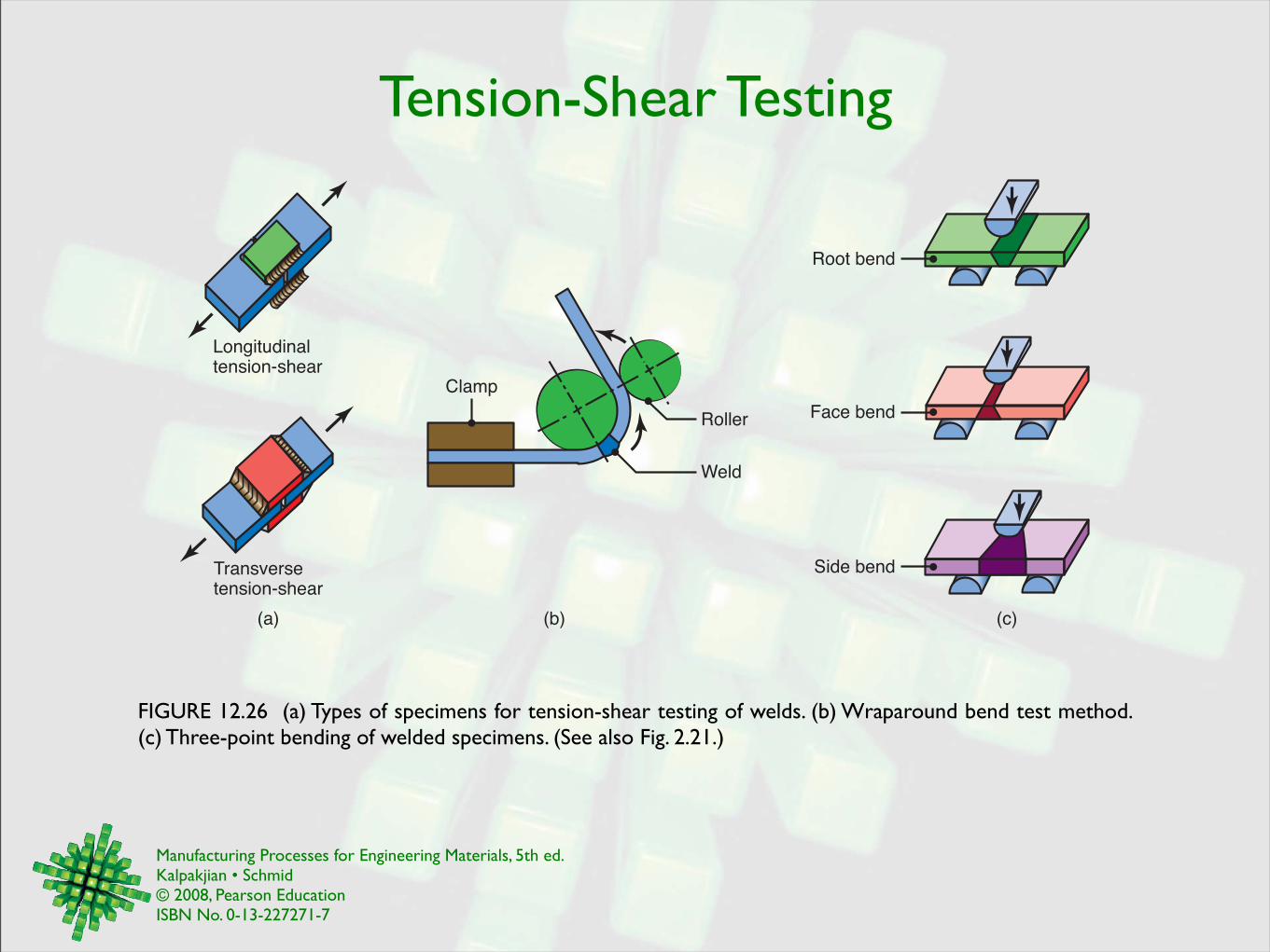
Tension-Shear Testing
FIGURE 12.26 (a) Types of specimens for tension-shear testing of welds. (b) Wraparound bend test method. (c) Three-point bending of welded specimens. (See also Fig. 2.21.)
(a) (b)
Longitudinaltension-shear
Transversetension-shear
(c)
Clamp
Roller
Weld
Side bend
Face bend
Root bend
Manufacturing Processes for Engineering Materials, 5th ed. Kalpakjian • Schmid© 2008, Pearson EducationISBN No. 0-13-227271-7
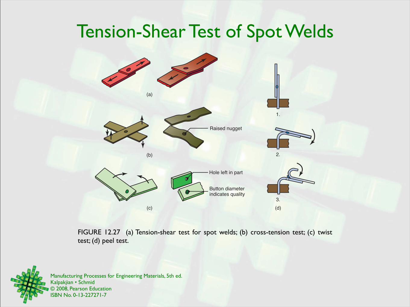
Tension-Shear Test of Spot Welds
FIGURE 12.27 (a) Tension-shear test for spot welds; (b) cross-tension test; (c) twist test; (d) peel test.
Hole left in part
Button diameterindicates quality
(c)
(b)
(a)
(d)
1.
2.
3.
Raised nugget
Manufacturing Processes for Engineering Materials, 5th ed. Kalpakjian • Schmid© 2008, Pearson EducationISBN No. 0-13-227271-7
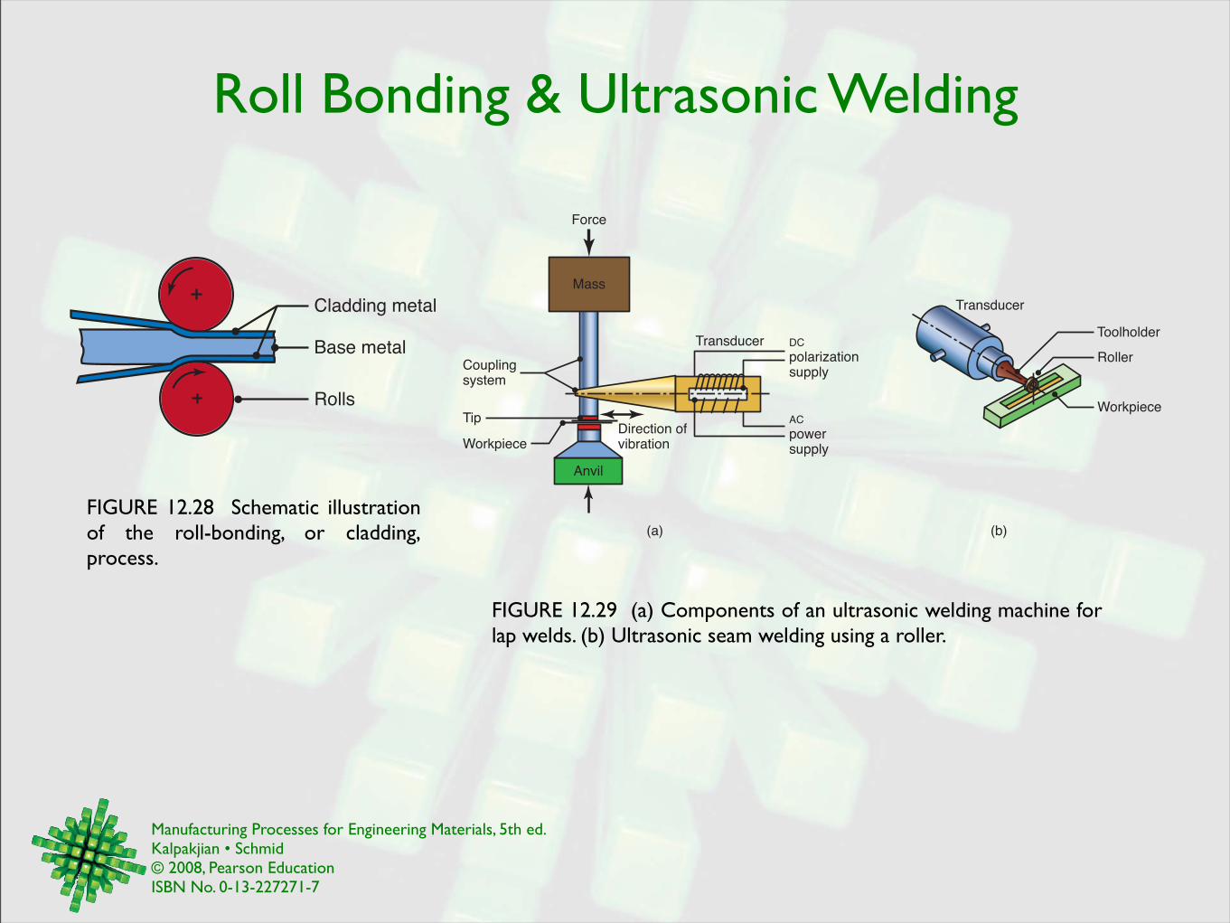
Roll Bonding & Ultrasonic Welding
FIGURE 12.28 Schematic illustration of the roll-bonding, or cladding, process.
Rolls
Cladding metal
Base metal
FIGURE 12.29 (a) Components of an ultrasonic welding machine for lap welds. (b) Ultrasonic seam welding using a roller.
Mass
Anvil
Transducer DC
polarizationsupply
AC
powersupply
Direction ofvibration
(a)
Force
Couplingsystem
Tip
Workpiece
(b)
Transducer
Toolholder
Roller
Workpiece
Manufacturing Processes for Engineering Materials, 5th ed. Kalpakjian • Schmid© 2008, Pearson EducationISBN No. 0-13-227271-7
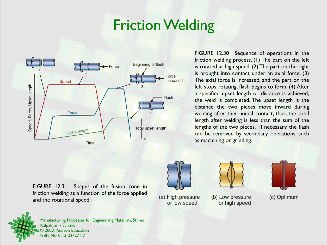
Friction Welding
FIGURE 12.31 Shapes of the fusion zone in friction welding as a function of the force applied and the rotational speed.
Forceincreased
Beginning of flash
Flash
1.2.
3.
4.
Force
Speed
Sp
ee
d,
Fo
rce,
Up
se
t le
ng
th
Time
Force
Total upset lengthUpset length
FIGURE 12.30 Sequence of operations in the friction welding process. (1) The part on the left is rotated at high speed. (2) The part on the right is brought into contact under an axial force. (3) The axial force is increased, and the part on the left stops rotating; flash begins to form. (4) After a specified upset length or distance is achieved, the weld is completed. The upset length is the distance the two pieces move inward during welding after their initial contact; thus, the total length after welding is less than the sum of the lengths of the two pieces. If necessary, the flash can be removed by secondary operations, such as machining or grinding.
(a) High pressure or low speed
(b) Low pressure or high speed
(c) Optimum
Manufacturing Processes for Engineering Materials, 5th ed. Kalpakjian • Schmid© 2008, Pearson EducationISBN No. 0-13-227271-7
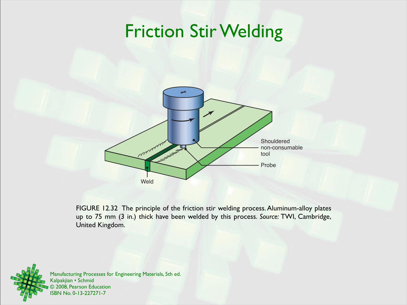
Friction Stir Welding
FIGURE 12.32 The principle of the friction stir welding process. Aluminum-alloy plates up to 75 mm (3 in.) thick have been welded by this process. Source: TWI, Cambridge, United Kingdom.
Shouldered
non-consumable
tool
Weld
Probe
Manufacturing Processes for Engineering Materials, 5th ed. Kalpakjian • Schmid© 2008, Pearson EducationISBN No. 0-13-227271-7
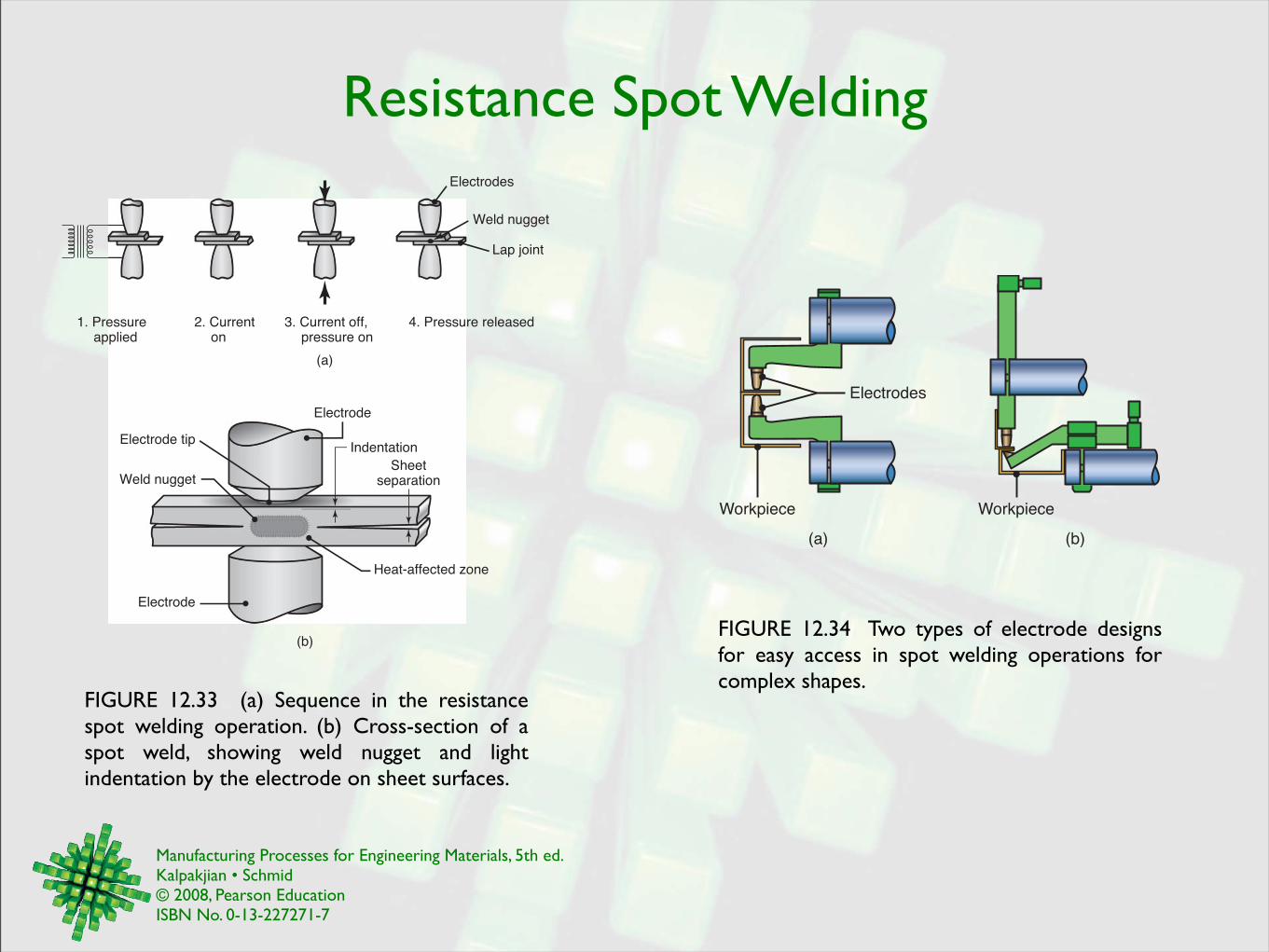
Resistance Spot Welding
FIGURE 12.33 (a) Sequence in the resistance spot welding operation. (b) Cross-section of a spot weld, showing weld nugget and light indentation by the electrode on sheet surfaces.
(b)
Electrode
Sheetseparation
Indentation
Heat-affected zone
Electrode tip
Weld nugget
Electrode
(a)
1. Pressure applied
2. Current on
3. Current off, pressure on
4. Pressure released
Lap joint
Weld nugget
Electrodes
FIGURE 12.34 Two types of electrode designs for easy access in spot welding operations for complex shapes.
(a) (b)
Workpiece
Electrodes
Workpiece
Manufacturing Processes for Engineering Materials, 5th ed. Kalpakjian • Schmid© 2008, Pearson EducationISBN No. 0-13-227271-7
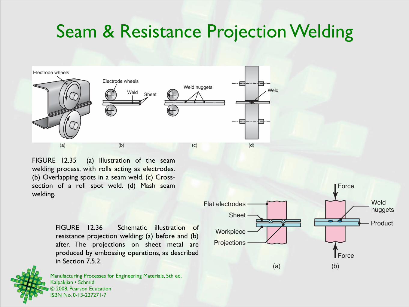
Seam & Resistance Projection Welding
FIGURE 12.35 (a) Illustration of the seam welding process, with rolls acting as electrodes. (b) Overlapping spots in a seam weld. (c) Cross-section of a roll spot weld. (d) Mash seam welding.
Electrode wheels
Electrode wheels
Weld Sheet
(b)(a) (c) (d)
WeldWeld nuggets
FIGURE 12.36 Schematic illustration of resistance projection welding: (a) before and (b) after. The projections on sheet metal are produced by embossing operations, as described in Section 7.5.2.
Flat electrodes
Sheet
Workpiece
Projections
Weldnuggets
Product
Force
Force
(a) (b)
Manufacturing Processes for Engineering Materials, 5th ed. Kalpakjian • Schmid© 2008, Pearson EducationISBN No. 0-13-227271-7
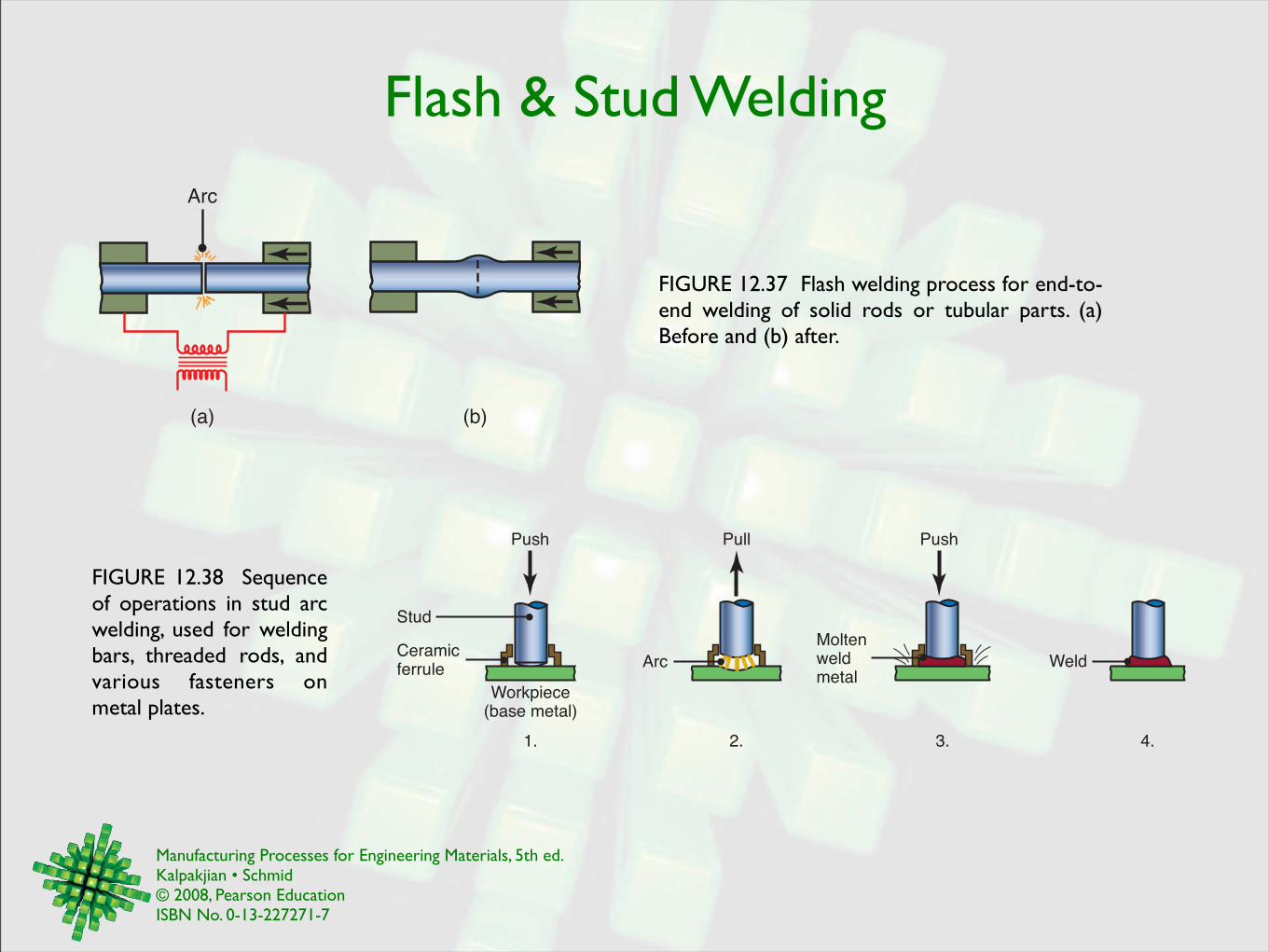
Flash & Stud Welding
FIGURE 12.37 Flash welding process for end-to-end welding of solid rods or tubular parts. (a) Before and (b) after.
Arc
(a) (b)
FIGURE 12.38 Sequence of operations in stud arc welding, used for welding bars, threaded rods, and various fasteners on metal plates.
Weld
Push PushPull
Moltenweldmetal
ArcCeramicferrule
Stud
Workpiece(base metal)
1. 2. 3. 4.
Manufacturing Processes for Engineering Materials, 5th ed. Kalpakjian • Schmid© 2008, Pearson EducationISBN No. 0-13-227271-7
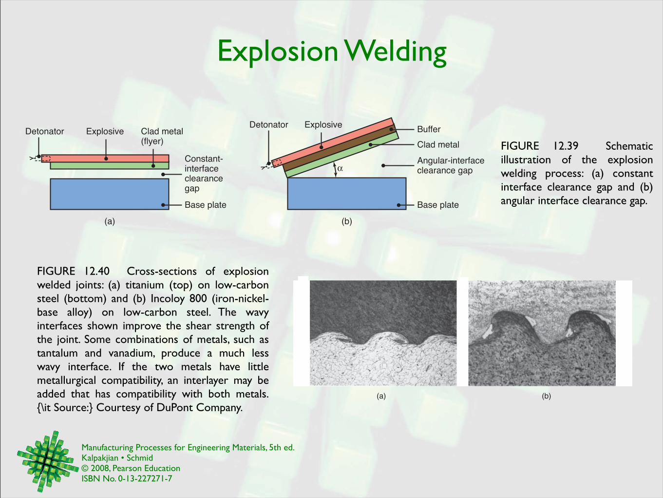
Explosion Welding
FIGURE 12.39 Schematic illustration of the explosion welding process: (a) constant interface clearance gap and (b) angular interface clearance gap.
(a) (b)
Detonator Explosive Clad metal(flyer)
Constant-interfaceclearancegap
Base plate
Detonator ExplosiveBuffer
Clad metal
Angular-interfaceclearance gap
Base plate
FIGURE 12.40 Cross-sections of explosion welded joints: (a) titanium (top) on low-carbon steel (bottom) and (b) Incoloy 800 (iron-nickel-base alloy) on low-carbon steel. The wavy interfaces shown improve the shear strength of the joint. Some combinations of metals, such as tantalum and vanadium, produce a much less wavy interface. If the two metals have little metallurgical compatibility, an interlayer may be added that has compatibility with both metals. {\it Source:} Courtesy of DuPont Company.
(a) (b)
Manufacturing Processes for Engineering Materials, 5th ed. Kalpakjian • Schmid© 2008, Pearson EducationISBN No. 0-13-227271-7
Diffusion Bonding
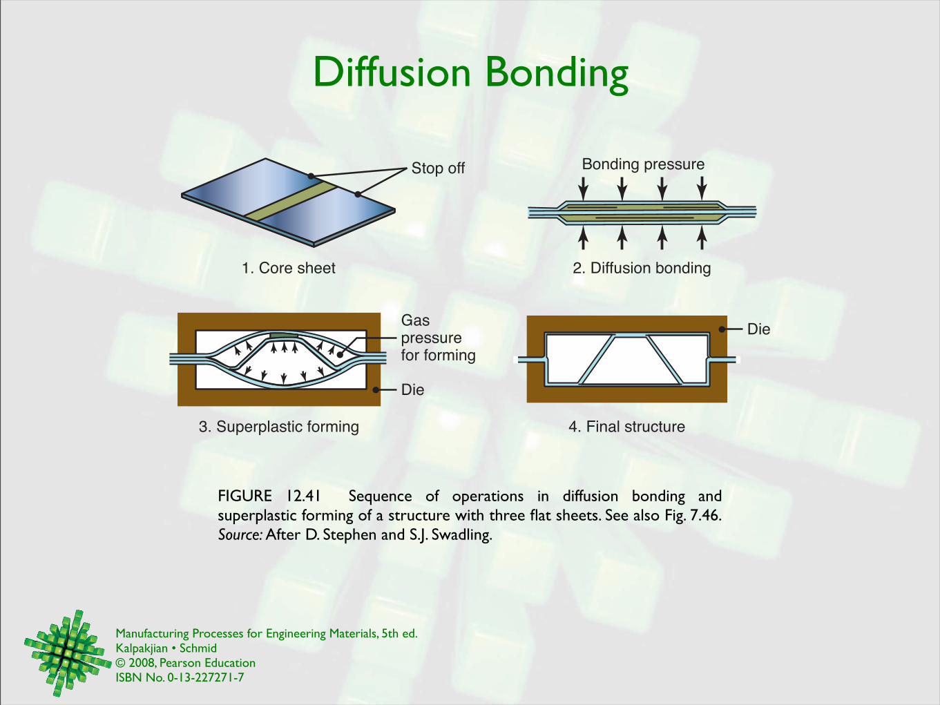
FIGURE 12.41 Sequence of operations in diffusion bonding and superplastic forming of a structure with three flat sheets. See also Fig. 7.46. Source: After D. Stephen and S.J. Swadling.
Bonding pressure
Die
Stop off
Die
Gaspressurefor forming
1. Core sheet 2. Diffusion bonding
3. Superplastic forming 4. Final structure
Manufacturing Processes for Engineering Materials, 5th ed. Kalpakjian • Schmid© 2008, Pearson EducationISBN No. 0-13-227271-7
Brazing & Braze Welding
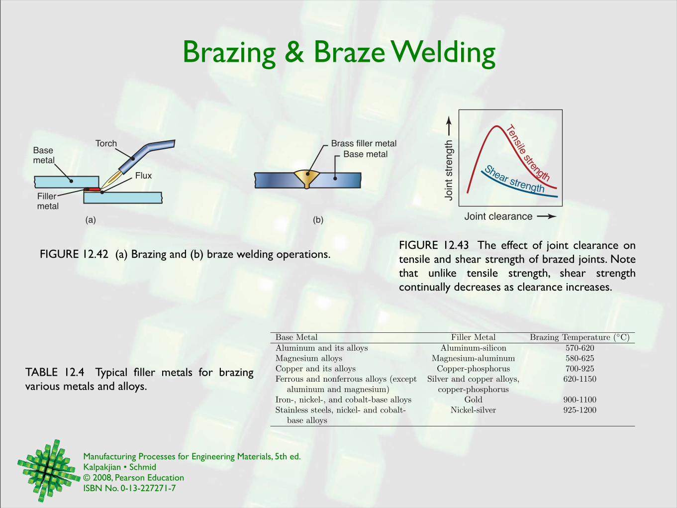
FIGURE 12.43 The effect of joint clearance on tensile and shear strength of brazed joints. Note that unlike tensile strength, shear strength continually decreases as clearance increases.
(a) (b)
Basemetal
Base metal
Fillermetal
Torch
Flux
Brass filler metal
FIGURE 12.42 (a) Brazing and (b) braze welding operations.
Joint clearance
Jo
int
str
en
gth
Tensile strength
Shear strength
Base Metal Filler Metal Brazing Temperature (!C)Aluminum and its alloys Aluminum-silicon 570-620Magnesium alloys Magnesium-aluminum 580-625Copper and its alloys Copper-phosphorus 700-925Ferrous and nonferrous alloys (except Silver and copper alloys, 620-1150
aluminum and magnesium) copper-phosphorusIron-, nickel-, and cobalt-base alloys Gold 900-1100Stainless steels, nickel- and cobalt- Nickel-silver 925-1200
base alloys
TABLE 12.4 Typical filler metals for brazing various metals and alloys.
Manufacturing Processes for Engineering Materials, 5th ed. Kalpakjian • Schmid© 2008, Pearson EducationISBN No. 0-13-227271-7
Furnace Brazing & Brazed Joints
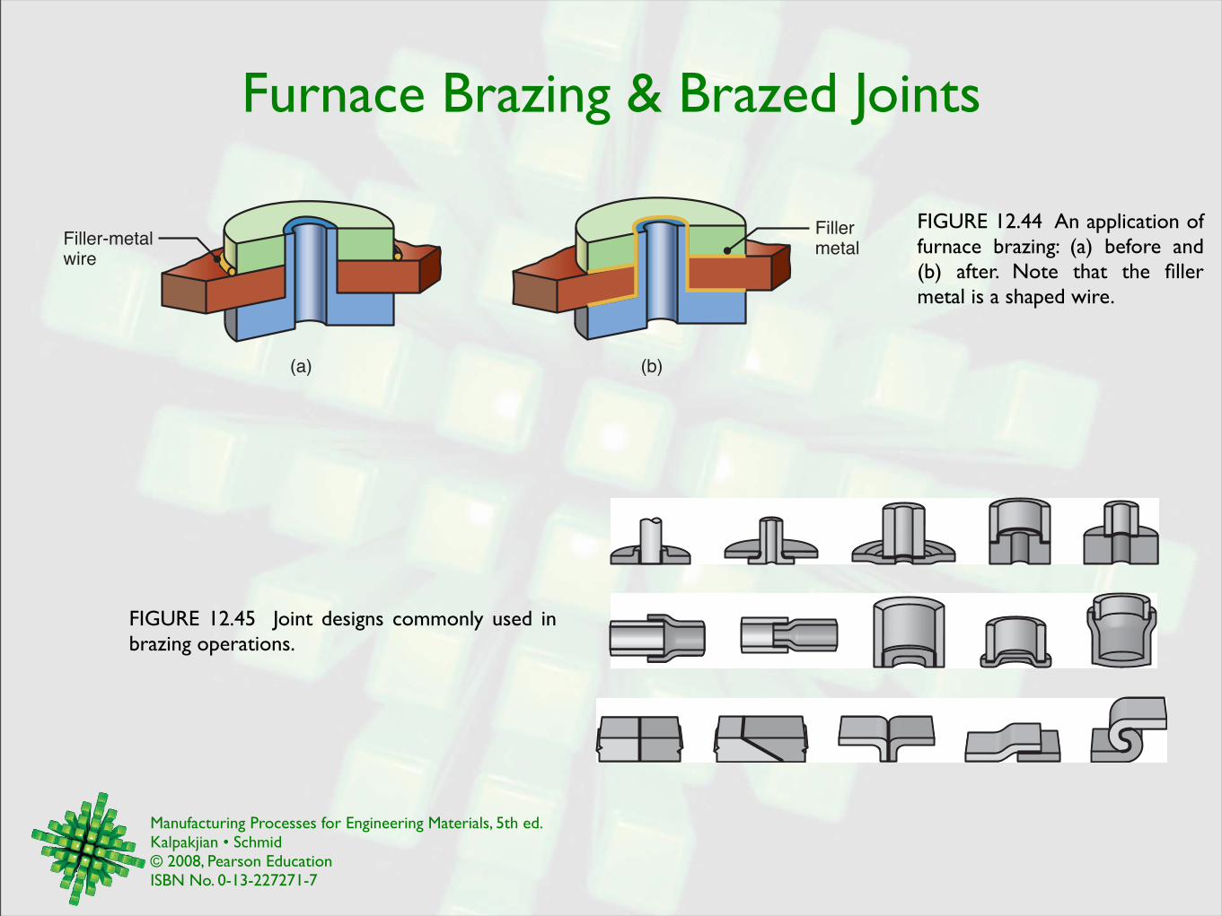
FIGURE 12.44 An application of furnace brazing: (a) before and (b) after. Note that the filler metal is a shaped wire.
(b)
Filler metal
Filler-metal wire
(a)
FIGURE 12.45 Joint designs commonly used in brazing operations.
Manufacturing Processes for Engineering Materials, 5th ed. Kalpakjian • Schmid© 2008, Pearson EducationISBN No. 0-13-227271-7
Solder Joints
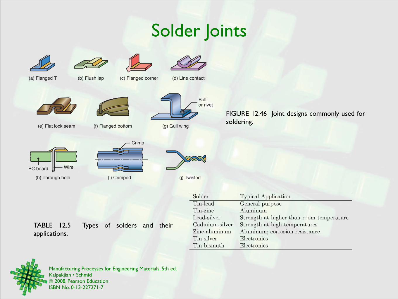
FIGURE 12.46 Joint designs commonly used for soldering.
(a) Flanged T (d) Line contact(b) Flush lap (c) Flanged corner
Boltor rivet
(e) Flat lock seam (f) Flanged bottom (g) Gull wing
Crimp
(h) Through hole (i) Crimped (j) Twisted
PC board Wire
Solder Typical ApplicationTin-lead General purposeTin-zinc AluminumLead-silver Strength at higher than room temperatureCadmium-silver Strength at high temperaturesZinc-aluminum Aluminum; corrosion resistanceTin-silver ElectronicsTin-bismuth Electronics
TABLE 12.5 Types of solders and their applications.
Manufacturing Processes for Engineering Materials, 5th ed. Kalpakjian • Schmid© 2008, Pearson EducationISBN No. 0-13-227271-7
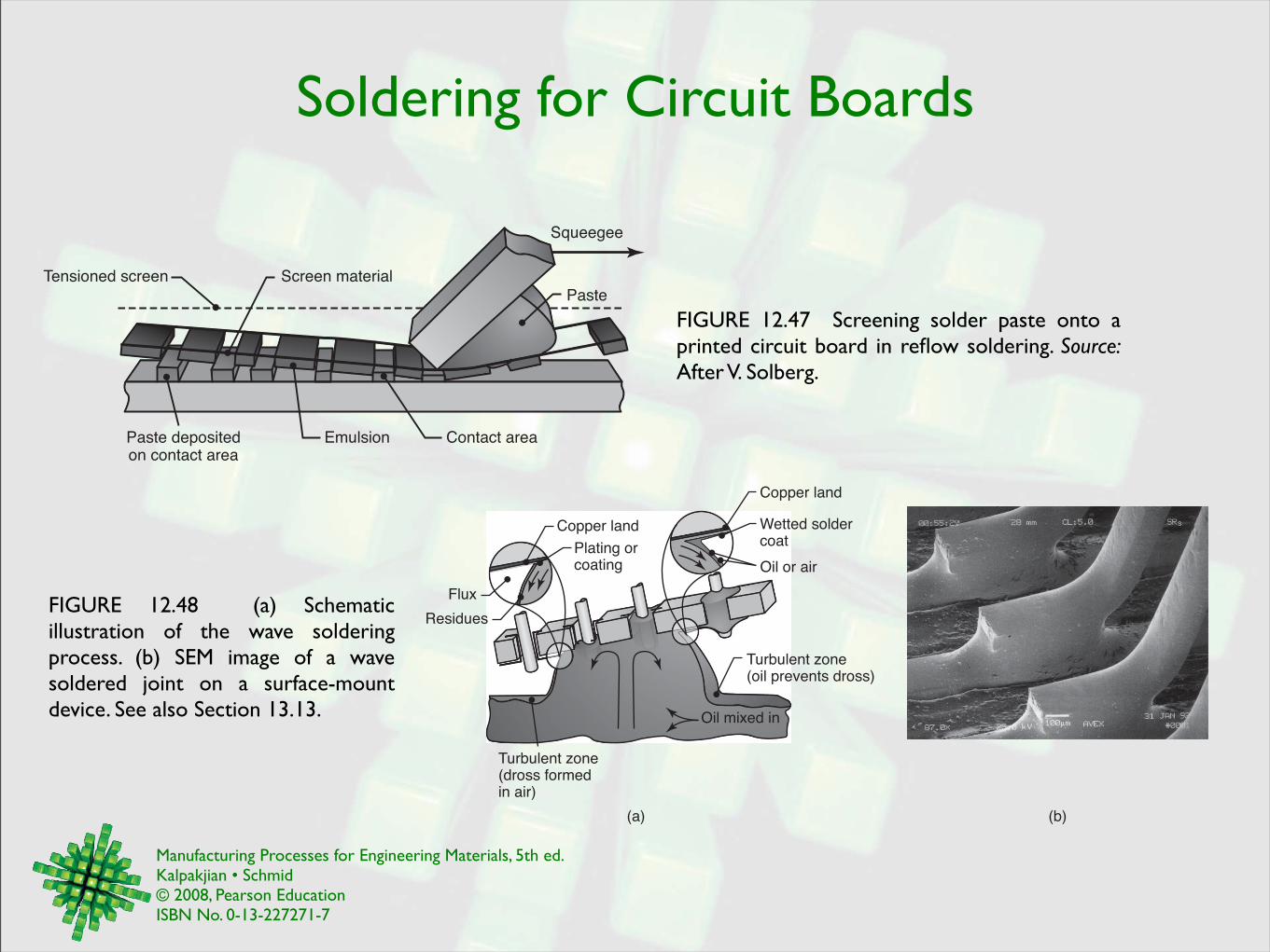
Soldering for Circuit Boards
FIGURE 12.47 Screening solder paste onto a printed circuit board in reflow soldering. Source: After V. Solberg.
Tensioned screen Screen material
Squeegee
Paste
Paste depositedon contact area
Emulsion Contact area
FIGURE 12.48 (a) Schematic illustration of the wave soldering process. (b) SEM image of a wave soldered joint on a surface-mount device. See also Section 13.13. Oil mixed in
Flux
Copper land
Copper land
Oil or air
Turbulent zone(oil prevents dross)
Turbulent zone(dross formedin air)
Plating or coating
Residues
(a) (b)
Wetted soldercoat
Manufacturing Processes for Engineering Materials, 5th ed. Kalpakjian • Schmid© 2008, Pearson EducationISBN No. 0-13-227271-7
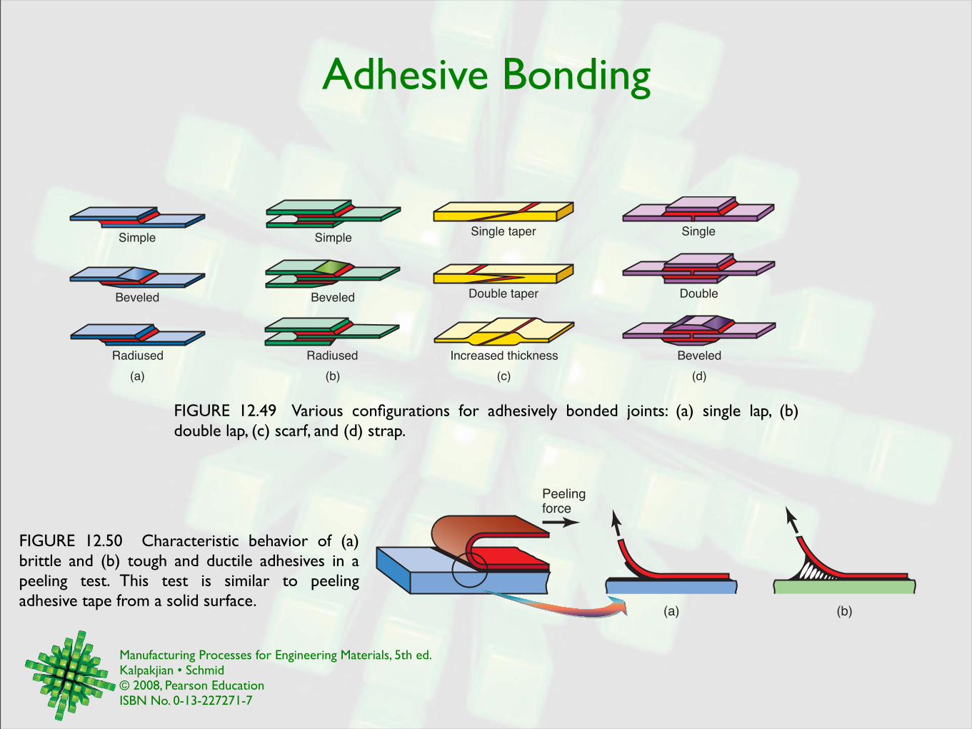
Adhesive Bonding
FIGURE 12.49 Various configurations for adhesively bonded joints: (a) single lap, (b) double lap, (c) scarf, and (d) strap.
(a)
Simple
Beveled
Radiused
(b)
Simple
Beveled
Radiused
(c)
Single taper
Double taper
Increased thickness
(d)
Single
Double
Beveled
FIGURE 12.50 Characteristic behavior of (a) brittle and (b) tough and ductile adhesives in a peeling test. This test is similar to peeling adhesive tape from a solid surface.
Peelingforce
(a) (b)
Manufacturing Processes for Engineering Materials, 5th ed. Kalpakjian • Schmid© 2008, Pearson EducationISBN No. 0-13-227271-7
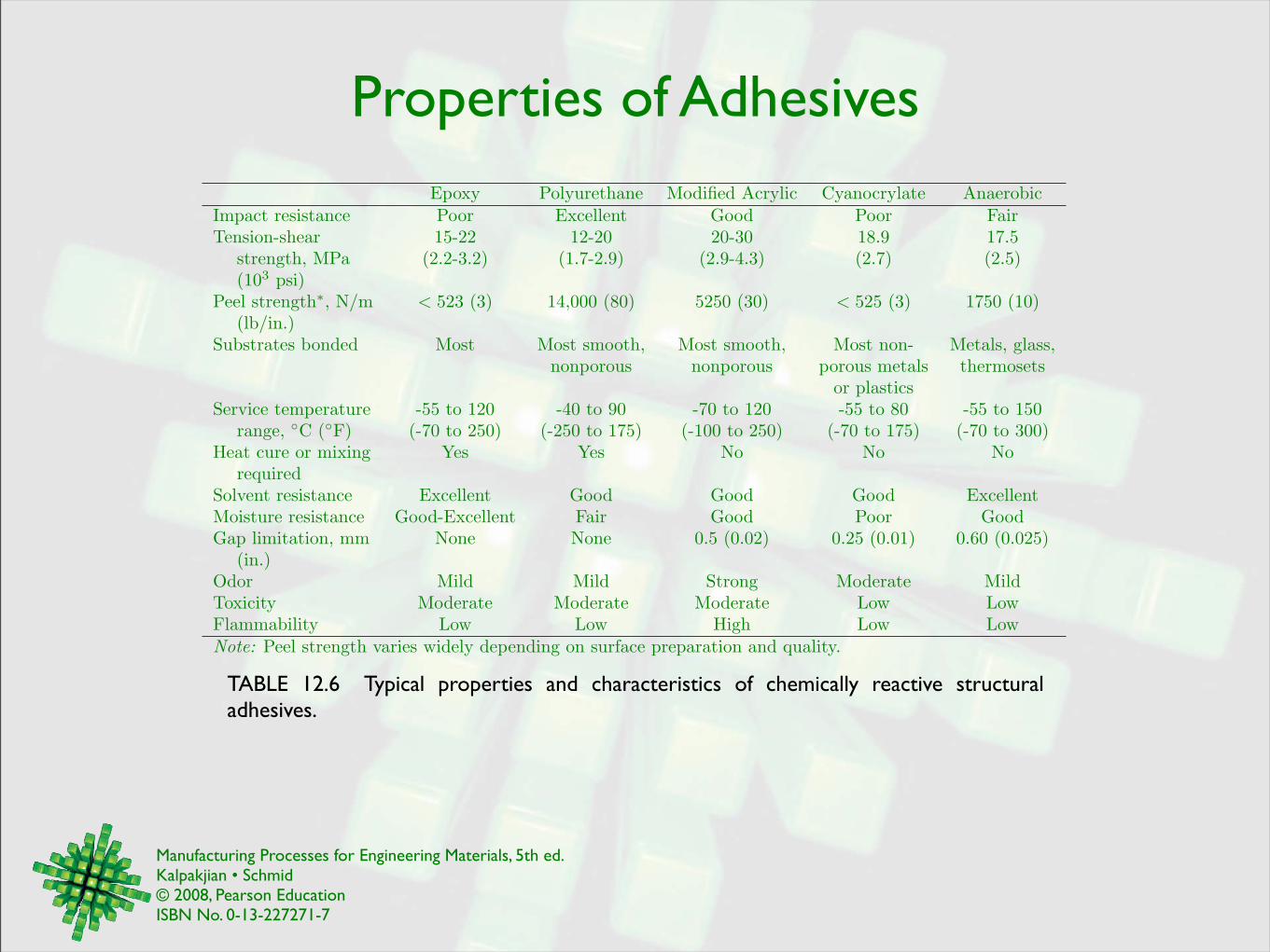
Properties of AdhesivesEpoxy Polyurethane Modified Acrylic Cyanocrylate Anaerobic
Impact resistance Poor Excellent Good Poor FairTension-shear 15-22 12-20 20-30 18.9 17.5
strength, MPa (2.2-3.2) (1.7-2.9) (2.9-4.3) (2.7) (2.5)(103 psi)
Peel strength!, N/m < 523 (3) 14,000 (80) 5250 (30) < 525 (3) 1750 (10)(lb/in.)
Substrates bonded Most Most smooth, Most smooth, Most non- Metals, glass,nonporous nonporous porous metals thermosets
or plasticsService temperature -55 to 120 -40 to 90 -70 to 120 -55 to 80 -55 to 150
range, "C ("F) (-70 to 250) (-250 to 175) (-100 to 250) (-70 to 175) (-70 to 300)Heat cure or mixing Yes Yes No No No
requiredSolvent resistance Excellent Good Good Good ExcellentMoisture resistance Good-Excellent Fair Good Poor GoodGap limitation, mm None None 0.5 (0.02) 0.25 (0.01) 0.60 (0.025)
(in.)Odor Mild Mild Strong Moderate MildToxicity Moderate Moderate Moderate Low LowFlammability Low Low High Low LowNote: Peel strength varies widely depending on surface preparation and quality.
TABLE 12.6 Typical properties and characteristics of chemically reactive structural adhesives.
Manufacturing Processes for Engineering Materials, 5th ed. Kalpakjian • Schmid© 2008, Pearson EducationISBN No. 0-13-227271-7
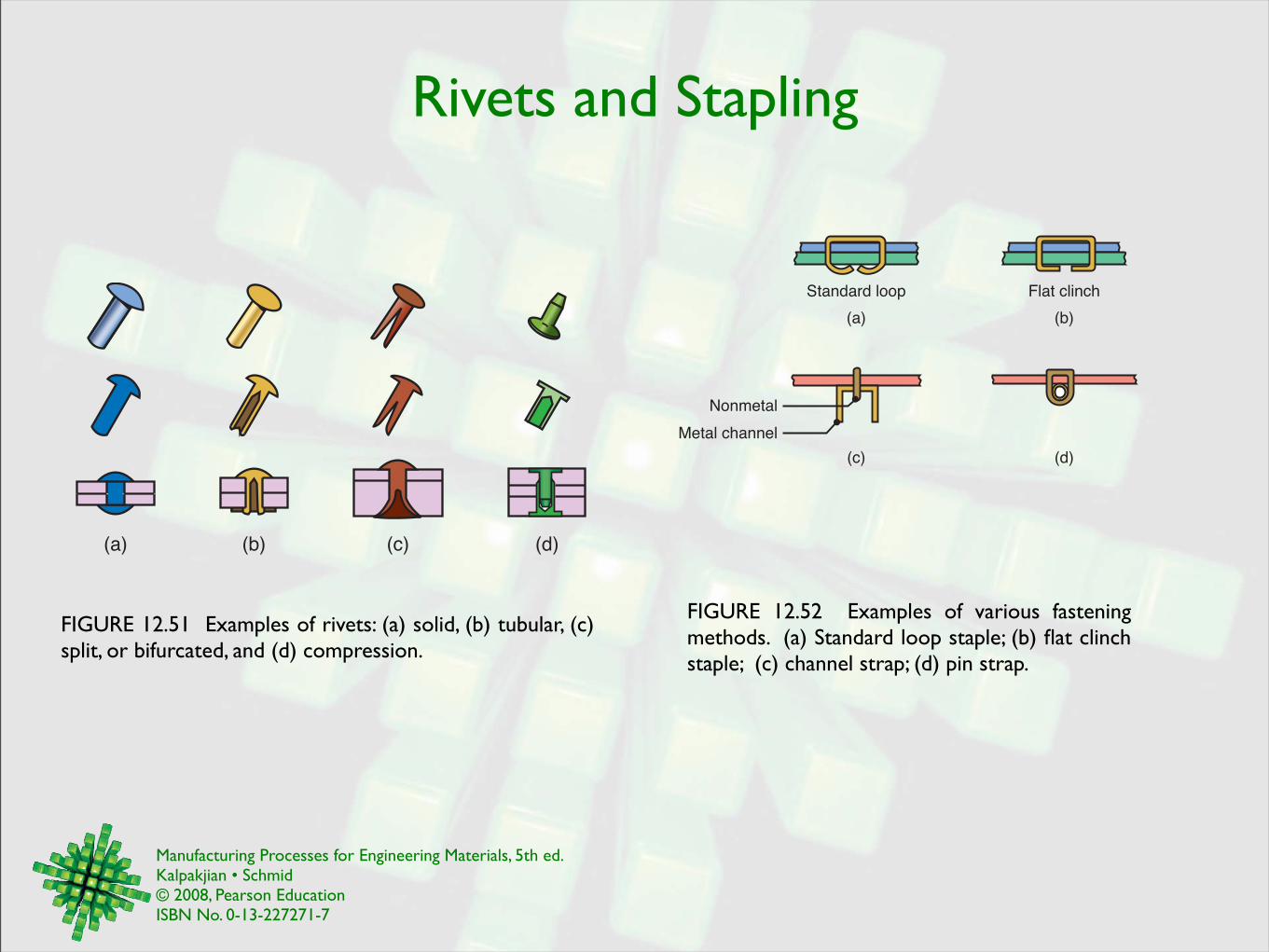
Rivets and Stapling
FIGURE 12.51 Examples of rivets: (a) solid, (b) tubular, (c) split, or bifurcated, and (d) compression.
(a) (b) (c) (d)
FIGURE 12.52 Examples of various fastening methods. (a) Standard loop staple; (b) flat clinch staple; (c) channel strap; (d) pin strap.
(a)
Standard loop
(b)
Flat clinch
(c) (d)
Nonmetal
Metal channel
Manufacturing Processes for Engineering Materials, 5th ed. Kalpakjian • Schmid© 2008, Pearson EducationISBN No. 0-13-227271-7
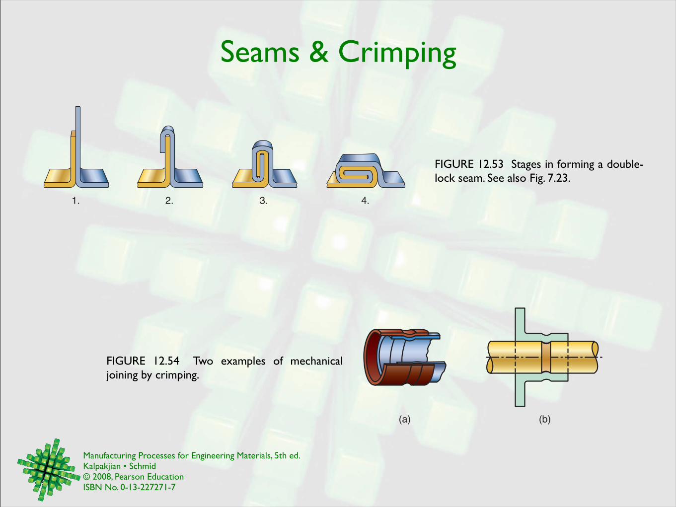
Seams & Crimping
FIGURE 12.53 Stages in forming a double-lock seam. See also Fig. 7.23.
1. 2. 3. 4.
FIGURE 12.54 Two examples of mechanical joining by crimping.
(a) (b)
Manufacturing Processes for Engineering Materials, 5th ed. Kalpakjian • Schmid© 2008, Pearson EducationISBN No. 0-13-227271-7
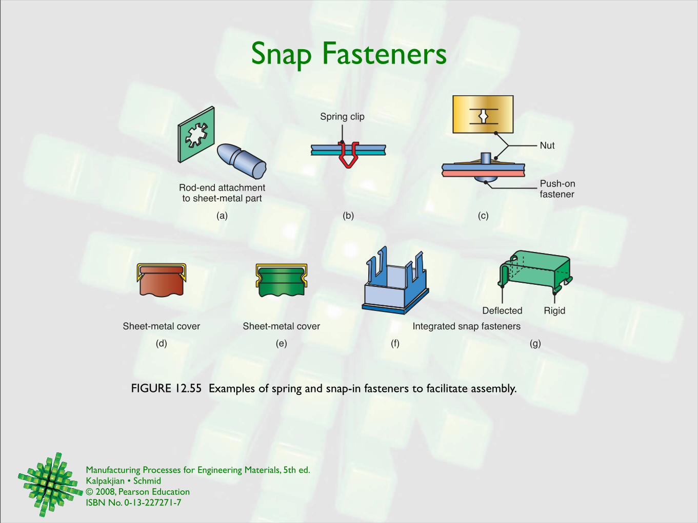
Snap Fasteners
FIGURE 12.55 Examples of spring and snap-in fasteners to facilitate assembly.
Sheet-metal cover
(d) (e) (f) (g)
Integrated snap fastenersSheet-metal cover
Deflected Rigid
Rod-end attachmentto sheet-metal part
(b)(a) (c)
Spring clip
Nut
Push-onfastener
Manufacturing Processes for Engineering Materials, 5th ed. Kalpakjian • Schmid© 2008, Pearson EducationISBN No. 0-13-227271-7
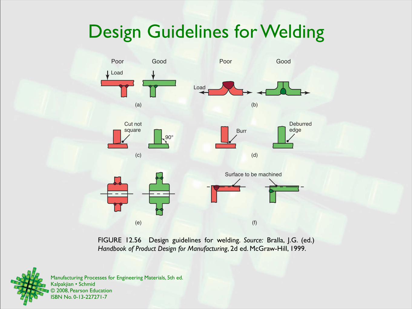
Design Guidelines for Welding
FIGURE 12.56 Design guidelines for welding. Source: Bralla, J.G. (ed.) Handbook of Product Design for Manufacturing, 2d ed. McGraw-Hill, 1999.
(a) (b)
(c) (d)
(e) (f)
Poor
Burr
GoodPoor Good
Deburrededge
Load
Load
Cut notsquare
90°
Surface to be machined
Manufacturing Processes for Engineering Materials, 5th ed. Kalpakjian • Schmid© 2008, Pearson EducationISBN No. 0-13-227271-7
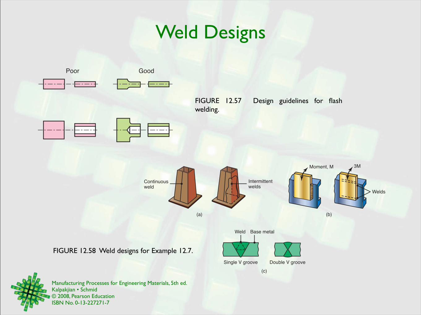
Weld Designs
FIGURE 12.58 Weld designs for Example 12.7.
Poor Good
FIGURE 12.57 Design guidelines for flash welding.
Continuousweld
(a)
Intermittentwelds
(c)
Double V groove
Weld Base metal
Single V groove
(b)
Moment, M 3M
Welds

Manufacturing Processes for Engineering Materials, 5th ed. Kalpakjian • Schmid© 2008, Pearson EducationISBN No. 0-13-227271-7
Brazing Designs
FIGURE 12.59 Examples of good and poor designs for brazing.
Good Poor Comments
Too little jointarea in shear
Improved designwhen fatigueloading is a factorto be considered
Insufficientbonding
Manufacturing Processes for Engineering Materials, 5th ed. Kalpakjian • Schmid© 2008, Pearson EducationISBN No. 0-13-227271-7
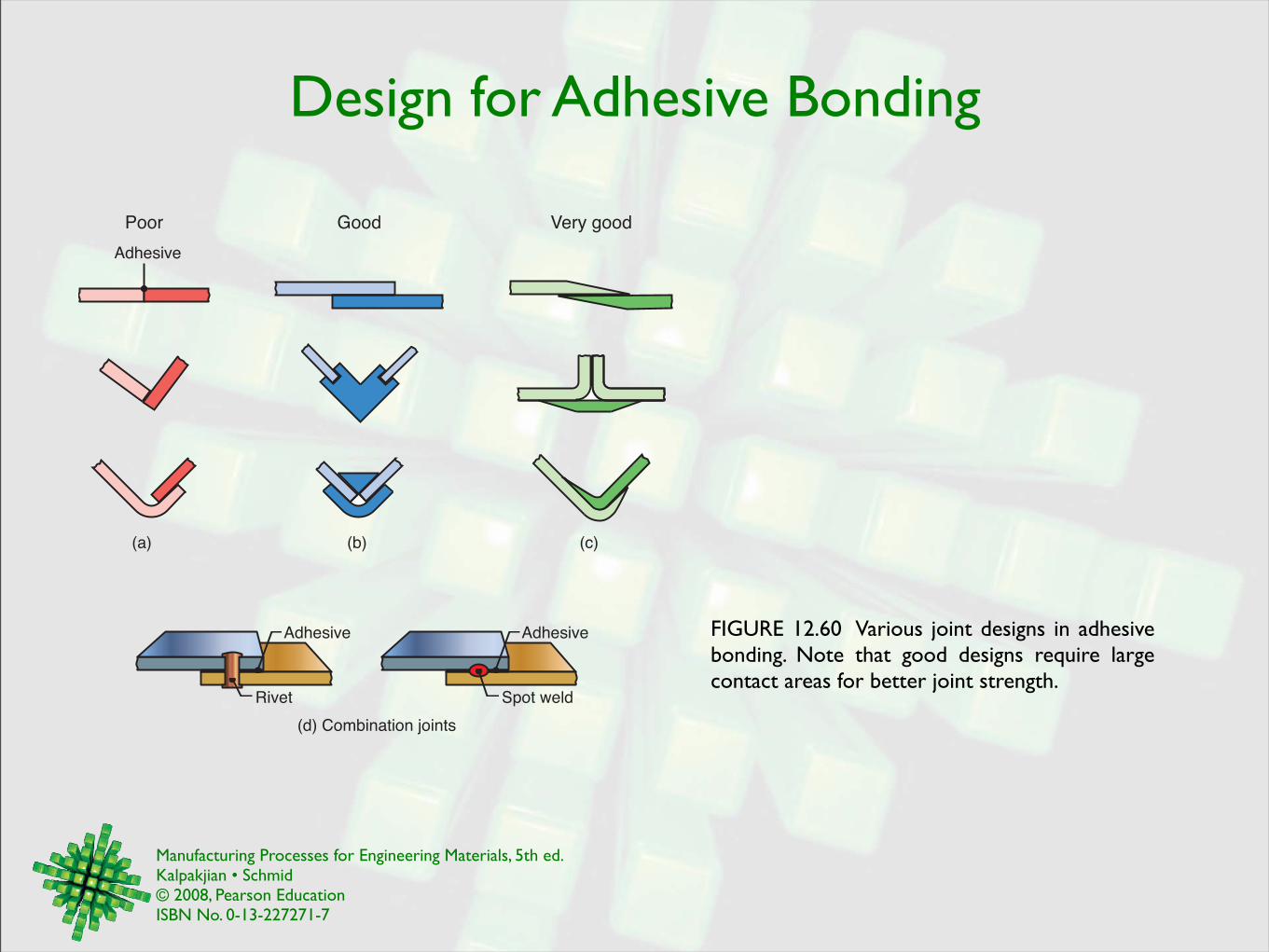
Design for Adhesive Bonding
FIGURE 12.60 Various joint designs in adhesive bonding. Note that good designs require large contact areas for better joint strength.
(d) Combination joints
Adhesive Adhesive
Rivet Spot weld
Good Very goodPoor
Adhesive
(a) (b) (c)
Manufacturing Processes for Engineering Materials, 5th ed. Kalpakjian • Schmid© 2008, Pearson EducationISBN No. 0-13-227271-7
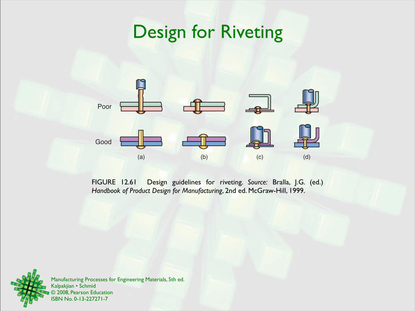
Design for Riveting
FIGURE 12.61 Design guidelines for riveting. Source: Bralla, J.G. (ed.) Handbook of Product Design for Manufacturing, 2nd ed. McGraw-Hill, 1999.
(c) (d)(b)
Poor
Good
(a)
Manufacturing Processes for Engineering Materials, 5th ed. Kalpakjian • Schmid© 2008, Pearson EducationISBN No. 0-13-227271-7
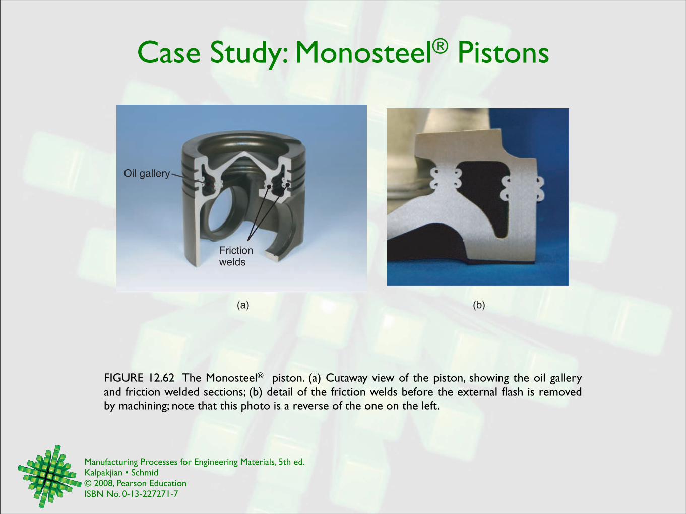
Case Study: Monosteel® Pistons
FIGURE 12.62 The Monosteel® piston. (a) Cutaway view of the piston, showing the oil gallery and friction welded sections; (b) detail of the friction welds before the external flash is removed by machining; note that this photo is a reverse of the one on the left.
Oil gallery
Friction welds
(a) (b)