A Broad Band Imager for the European Solar Telescopesait.oat.ts.astro.it/MSAIS/19/PDF/101.pdf ·...
4
Mem. S.A.It. Suppl. Vol. 19, 101 c SAIt 2012 Memorie della Supplementi M. Munari 1 , S. Scuderi 1 ,M. Cecconi 2 and F. Zuccarello 3 1 Istituto Nazionale di Astrofisica – Osservatorio Astrofisco di Catania, Via Santa Sofia 78, I-95123 Catania, Italy 2 Istituto Nazionale di Astrofisica – Fundaci ´ on Galileo Galilei, Rambla Jos´ e Ana Fernandez P´ erez 7, E-38712 Bre ˜ na Baja, La Palma (TF), Canary Islands, Spain 3 Dipartimento di Fisica e Astronomia, Sezione Astrofisica, Universit´ a di Catania, Via S. Sofia 78, 95123 Catania, Italy Abstract. The European Solar Telescope (EST) is a joint project of several European research institutes to design and realize a 4-m class solar telescope. The EST Broad Band Imager is one of the baseline instruments of EST. It will obtain diffraction limited images over the full field of view of EST at multiple wavelengths and high frame rate. Its scientific objectives are the study of fundamental astrophysical processes at their intrinsic scales in the Sun’s atmosphere. Here we report on the current optical design of the instrument. Key words. Solar telescopes – Optical design – Instrumentation 1. Introduction EST (European Solar Telescope) will be a 4m class solar telescope. It will have a Gregorian on-axis optical configuration and an alt-azimuthal mounting and it will be installed at the Canary Islands, on the top of a 30m tower, so to improve the local seeing condi- tions. A multi-conjugate adaptive optics sys- tem and a derotation system will be integrated in the transfer optics between the telescope fo- cus and a F/50 science focus in a two floor Coud´ e room, where three types of instruments, each composed of different spectral channels, will be installed: a Broad-Band Imager (BBI), a Narrow-Band Tunable Spectropolarimeter and a Grating Spectropolarimeter. Light com- ing from EST will be sent to the instruments Send offprint requests to: M.Munari Fig. 1. Light distribution among instruments from Cavaller et al. (2010) following a light distribution scheme similar to that shown in Figure 1. The main characteris- tics of EST are summarized in Table 1.
Transcript of A Broad Band Imager for the European Solar Telescopesait.oat.ts.astro.it/MSAIS/19/PDF/101.pdf ·...

Mem. S.A.It. Suppl. Vol. 19, 101c© SAIt 2012
Memorie della
Supplementi
A Broad Band Imager for the European SolarTelescope
M. Munari1, S. Scuderi1,M. Cecconi2 and F. Zuccarello3
1 Istituto Nazionale di Astrofisica – Osservatorio Astrofisco di Catania, Via Santa Sofia 78,I-95123 Catania, Italy
2 Istituto Nazionale di Astrofisica – Fundacion Galileo Galilei, Rambla Jose Ana FernandezPerez 7, E-38712 Brena Baja, La Palma (TF), Canary Islands, Spain
3 Dipartimento di Fisica e Astronomia, Sezione Astrofisica, Universita di Catania, Via S.Sofia 78, 95123 Catania, Italy
Abstract. The European Solar Telescope (EST) is a joint project of several Europeanresearch institutes to design and realize a 4-m class solar telescope. The EST Broad BandImager is one of the baseline instruments of EST. It will obtain diffraction limited imagesover the full field of view of EST at multiple wavelengths and high frame rate. Its scientificobjectives are the study of fundamental astrophysical processes at their intrinsic scales inthe Sun’s atmosphere. Here we report on the current optical design of the instrument.
Key words. Solar telescopes – Optical design – Instrumentation
1. Introduction
EST (European Solar Telescope) will be a4m class solar telescope. It will have aGregorian on-axis optical configuration and analt-azimuthal mounting and it will be installedat the Canary Islands, on the top of a 30mtower, so to improve the local seeing condi-tions. A multi-conjugate adaptive optics sys-tem and a derotation system will be integratedin the transfer optics between the telescope fo-cus and a F/50 science focus in a two floorCoude room, where three types of instruments,each composed of different spectral channels,will be installed: a Broad-Band Imager (BBI),a Narrow-Band Tunable Spectropolarimeterand a Grating Spectropolarimeter. Light com-ing from EST will be sent to the instruments
Send offprint requests to: M.Munari
Fig. 1. Light distribution among instruments fromCavaller et al. (2010)
following a light distribution scheme similar tothat shown in Figure 1. The main characteris-tics of EST are summarized in Table 1.
102 Munari: A Broad Band Imager for the European Solar Telescope
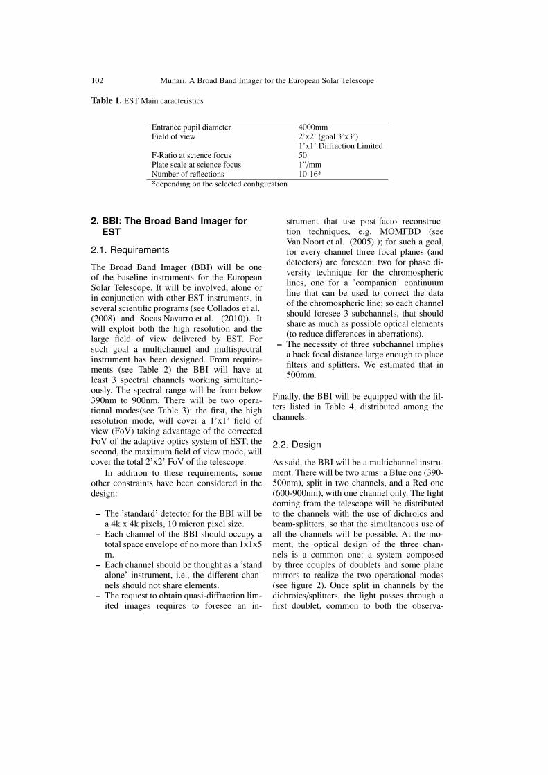
Table 1. EST Main caracteristics
Entrance pupil diameter 4000mmField of view 2’x2’ (goal 3’x3’)
1’x1’ Diffraction LimitedF-Ratio at science focus 50Plate scale at science focus 1”/mmNumber of reflections 10-16**depending on the selected configuration
2. BBI: The Broad Band Imager forEST
2.1. Requirements
The Broad Band Imager (BBI) will be oneof the baseline instruments for the EuropeanSolar Telescope. It will be involved, alone orin conjunction with other EST instruments, inseveral scientific programs (see Collados et al.(2008) and Socas Navarro et al. (2010)). Itwill exploit both the high resolution and thelarge field of view delivered by EST. Forsuch goal a multichannel and multispectralinstrument has been designed. From require-ments (see Table 2) the BBI will have atleast 3 spectral channels working simultane-ously. The spectral range will be from below390nm to 900nm. There will be two opera-tional modes(see Table 3): the first, the highresolution mode, will cover a 1’x1’ field ofview (FoV) taking advantage of the correctedFoV of the adaptive optics system of EST; thesecond, the maximum field of view mode, willcover the total 2’x2’ FoV of the telescope.
In addition to these requirements, someother constraints have been considered in thedesign:
– The ’standard’ detector for the BBI will bea 4k x 4k pixels, 10 micron pixel size.
– Each channel of the BBI should occupy atotal space envelope of no more than 1x1x5m.
– Each channel should be thought as a ’standalone’ instrument, i.e., the different chan-nels should not share elements.
– The request to obtain quasi-diffraction lim-ited images requires to foresee an in-
strument that use post-facto reconstruc-tion techniques, e.g. MOMFBD (seeVan Noort et al. (2005) ); for such a goal,for every channel three focal planes (anddetectors) are foreseen: two for phase di-versity technique for the chromosphericlines, one for a ’companion’ continuumline that can be used to correct the dataof the chromospheric line; so each channelshould foresee 3 subchannels, that shouldshare as much as possible optical elements(to reduce differences in aberrations).
– The necessity of three subchannel impliesa back focal distance large enough to placefilters and splitters. We estimated that in500mm.
Finally, the BBI will be equipped with the fil-ters listed in Table 4, distributed among thechannels.
2.2. Design
As said, the BBI will be a multichannel instru-ment. There will be two arms: a Blue one (390-500nm), split in two channels, and a Red one(600-900nm), with one channel only. The lightcoming from the telescope will be distributedto the channels with the use of dichroics andbeam-splitters, so that the simultaneous use ofall the channels will be possible. At the mo-ment, the optical design of the three chan-nels is a common one: a system composedby three couples of doublets and some planemirrors to realize the two operational modes(see figure 2). Once split in channels by thedichroics/splitters, the light passes through afirst doublet, common to both the observa-

Munari: A Broad Band Imager for the European Solar Telescope 103
Table 2. BBI Requirements
Number of spectral channels 3 channels working simultaneously (goal 5)Observation modes Optimum spatial resolution, Maximum field of viewMaximum Field of View 2’x2’Angular Resolution 0.04” @ 500 nm (goal of 0.03”), Optimum on a 60”x60” Field of ViewMosaic Mode 3’x3’ mosaic mode at optimal resolution (60”x60” patches)Wavelength Coverage From 390 nm to 900 nmWavelength Switching < 2 secondsMaximum bandpass shift 5x10⁻³nm (goal 3x10⁻³) @ 500nm, 30” from the field centerTransmission Total throughput > 30%Telecentricity At the detector
Fig. 2. Single channel Layout
Table 3. Observational Modes Data
High MaximumResolution FoV
Detector Format 4k x 4k 4k x 4kPixel Size 10 micron 10 micronSampling 0.016”/pix 0.03”/pixField of View 64” x 64” 2’ x 2’Scale 1.6”/mm 3”/mmF-Ratio 32 17
tional modes. After that, the beam can go onstraight through a second doublet, forming the’Maximum Field of View Mode’ focus on thedetector, or a couple of 45 deg mirrors can beinserted to deviate the light toward a differentdoublet, and another couple can deviate againthe beam to the detector, creating the ’HighResolution Mode’ focus. Each channel will bethen split in three subchannels, for reconstruc-
Table 4. BBI Filters list
Filter Name C FWHM Spectral Feature[nm] [nm]
BBI-WF1 388.30 0.5 CN band headBBI-WF2 395.37 0.5 Ca II H continuumBBI-NF1 396.88 0.05 Ca II H coreBBI-NF2 396.47 0.05 Ca II H wingBBI-WF3 417.00 0.5 Paschen continuumBBI-WF4 430.50 0.5 G bandBBI-WF5 436.39 0.5 G band continuumBBI-NF3 656.28 0.1 HBBI-WF6 668.40 0.5 H continuumBBI-WF7 840.00 0.5 Brackett continuumBBI-NF4 854.20 0.05 Ca II IR
tion techniques purposes: after the last mov-able mirror, the beam is split again with twobeamsplitters, to form the three subchannels.Filters are placed immediatly before the detec-tors, so to limitate their dimensions, in a tele-centric configuration.
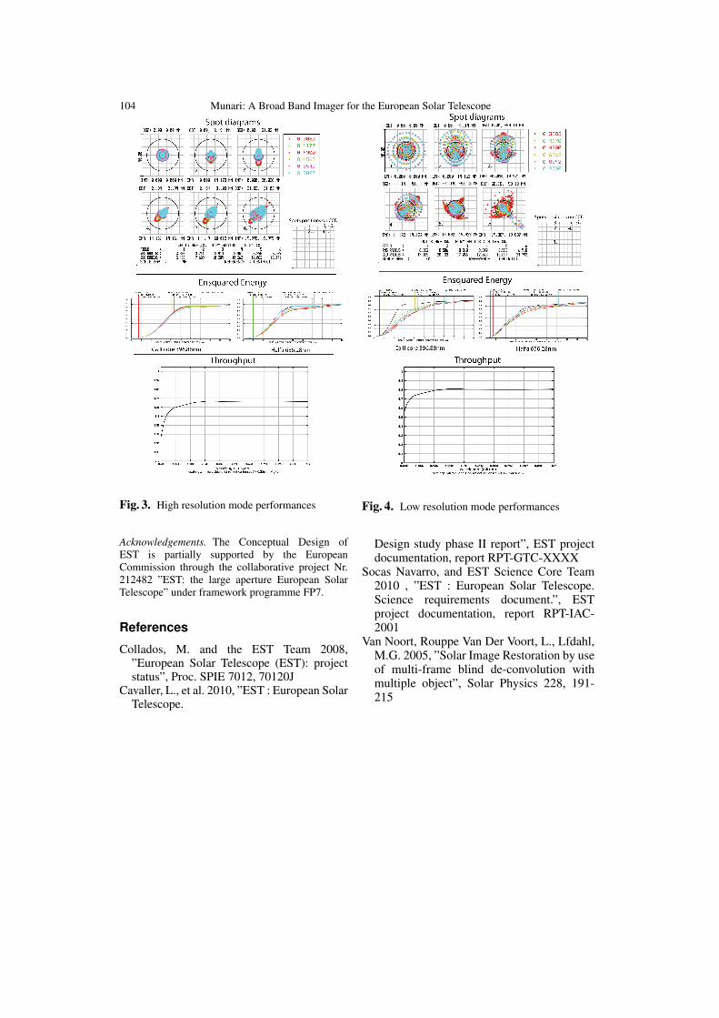
2.3. Performances
Spot diagrams, ensquared energies andthroughput at two different wavelengths andfor the two observational modes are shownin figures 3 and 4. From their examinationit is clear that the optical design satisfies therequirements.
104 Munari: A Broad Band Imager for the European Solar Telescope
Fig. 3. High resolution mode performances
Acknowledgements. The Conceptual Design ofEST is partially supported by the EuropeanCommission through the collaborative project Nr.212482 ”EST: the large aperture European SolarTelescope” under framework programme FP7.
References
Collados, M. and the EST Team 2008,”European Solar Telescope (EST): projectstatus”, Proc. SPIE 7012, 70120J
Cavaller, L., et al. 2010, ”EST : European SolarTelescope.
Fig. 4. Low resolution mode performances
Design study phase II report”, EST projectdocumentation, report RPT-GTC-XXXX
Socas Navarro, and EST Science Core Team2010 , ”EST : European Solar Telescope.Science requirements document.”, ESTproject documentation, report RPT-IAC-2001
Van Noort, Rouppe Van Der Voort, L., Lfdahl,M.G. 2005, ”Solar Image Restoration by useof multi-frame blind de-convolution withmultiple object”, Solar Physics 228, 191-215