A brief history of Fullriver Battery Mfg. Co., Ltd. · PDF fileThe normal voltages for the HGL...
16
Transcript of A brief history of Fullriver Battery Mfg. Co., Ltd. · PDF fileThe normal voltages for the HGL...


A brief history of Fullriver Battery Mfg. Co., Ltd. Product development… Fullriver Battery Manufacture Co., Ltd. was founded in 1995 and launched the HGL series . The HGL series batteries are
mainly for general use purposes, i.e. low power UPS, Security & Alarm Systems, Emergency Lighting, Office machines, etc.
The normal voltages for the HGL series are 6V and 12V; the capacity is ranged from 0.8Ah to 260Ah.
In 2001, the HGXL series was launched. This series is a 2V stationary maintenance-free battery, designed as high capacity,
long life and high power batteries. These are mainly used for high capacity UPS systems, telecommunications and solar battery
systems applications. The capacity of this series is ranged from 50 AH to 3000 AH.
In 2003, the HGHL series was launched. This series performs well in both high rate discharge and float service applications.
This series was specially designed for UPS standby power supply. It is also available for other float service applications, such
as emergency power supply, communication power supply, etc. the power of this series is ranged from 35W to 910W.
In 2004, the FAT series and the DC series were launched .The FAT series also has the characteristics of high rate discharge.
They are widely used in UPS systems and telecommunications. The FAT series features front terminal connections for fast and
easy installation and maintenance. The monobloc's compact design is suitable for 19", 23"and ETSI racking. The capacity of
FAT series is ranged from 55Ah to 175Ah.
The DC series is specially designed and used for deep cycle applications, which may require many more cycles. This series
also has excellent recovery from deep discharge. The DC series is mainly used in golf trolley, golf caddy, forklift, electric
wheelchairs, floor cleaning machines, marine, photovoltaic systems, and more.
In 2008, we started research, development, and manufacturing of the HC series. This series is especially used for engine
starting, which requires superior cranking performance at lower temperatures, for high current discharge. These batteries can
also be fitted with the protective steel case and TP brass terminals.
In 2010, the FSG series was launched. Which use revolutionary Super GEL long life plate technology and are designed
specifically for solar energy and wind energy applications. The designed life is 20 years in float service at 20 .the battery℃ can
be used in a wide operating temperature range from -20 to 50 .℃ ℃
In 2011, the DCG series was launched. Fullriver Deep-Cycle Gel(DCG)batteries are maintenance free and require no watering,
while providing you with the unmatched quality and power of Fullriver's advanced deep cycle technology. Fullriver offers a
complete portfolio of Deep-Cycle Gel(DCG)products, featuring these benefits: Long-lasting runtime and battery life in the most
demanding of applications; Proprietary Gel formulation prevents stratification; Superior engineering offers exceptional
durability.
Fullriver batteries Qualifications, Approvals, and Certifications
� Network Access License for Telecommunications Equipm ent
(Ministry of information Industry.PRC)
� DOT 49CFR173.159 (d) (i) and (ii) (Non-hazardous shipping)
� IEC 61056-1; 2004 (General purpose lead-acid batteries, valve regulated types)
� IEC 60896-2: 2004 (Stationary lead-acid batteries, valve regulated types)
� JIS C8704-2: 2006 (Stationary lead-acid batteries, valve regulated types)
� JIS C8702-1: 2003 (Small-sized valve regulated lead-acid batteries)

General Features
• Valve regulated lead acid battery.
• Dry cell technology with an absorbed glass mat.
• It has safety, low resistance so recharge is easy
and energy output is more remarkable
• 5S.Pulse discharge capabilities
• Low self discharge, the self discharge rate below 4%
per month
• High rate discharge construction
• Deep discharge recoverability
• Can be choose to install metal case(Except
HC64,HC65,HC75) and fitted with TP brass
automotive terminal
• Operation temperature range: -22°F (-30°C) to
122°F (50°C)
Benefits
• High capacity starting power-to start any size
engines • Highest reserve capacity in the industry-to power a
wide range of accessories • Superior conductivity – brass terminals provide
greater electrical transmission • Durability – rugged design to withstand shock and
vibration
• Charge efficiency – faster recharge than
conventional wet batteries
• Convenience – maintenance free sealed
construction – no water needed
• Safety – DOT,IATA,IMDG and ICAO CERTIFIED as
non-spillable
Applications
• Auto/LTV
• Marine
• Extreme racing
• Heavy duty/Commercial
• Car audio accessories
• Engine starting
• Power sports
• Vehicle fleet

Characteristics
Self Discharge
All lead acid batteries experience self-discharge in open circuit. The result is that open circuit voltage decreases,
and the capacity also decreases. During storage please note:
a、 The self-discharge rate is related with ambient temperature. The self-discharge rate is smaller when the
ambient temperature is lower, otherwise is larger. The required temperature of HC batteries' storage
environment is from 0℃ to 35℃. The storage place must be clean, ventilated and dry.
b、 An important parameter in storage is open circuit voltage, which is related with density of the electrolyte. If the
open circuit voltage is lower than 12.6V/block, or have been stored for three months, the batteries should be
supplementally charged to avoid damage caused by self discharge.
c、 All batteries, which are ready to store, should be fully charged before storage. It’s suggested to record the
storage time in the periodic maintenance record and record the time when another necessary supplemental
charge should be made.
d、 The quality certificates and packages of HC batteries record the latest charge time of the batteries, next charge
time can be calculated according to this charge time.
Temperature Conditions
Recommended temperature ranges for charging, discharging and storing the battery are tabulated below.
Table 1: Temperature conditions:
Charge 32℉(0℃)~104℉(40℃)
Discharge 5℉(-15℃)~122℉(50℃)
Storage 5℉(-15℃)~104℉(40℃)
Residual capacity test result
0 3 6 9 12 150
20
40
80
(%)100
Storage time (Months)
Res
idua
l cap
acity
40 (104 )℃ ℃
30 (86 )℃ ℃
0 (32 )℃ ℃
10 (50 )℃ ℃
20 (68 )℃ ℃
No need for refresh charge,however,to ensure 100% ratedcapacity,it's important to full chargethe battery before use
Refresh charge is needed. (batterycapacity could be resumed afterrefresh chargeis applied
It's very likely that the batterycapacity could not be resumedeven with refreshcharge.(please do not store thebattery under this condition.)
60
BatteryOCVRefresh charge
Abowe2.11V/cell
Between2.02V-2.11V
/cell
Below2.02V/cell
figure 1: Residual Capacity Vs. Storage time

Available Capacity, Measured By Open Circuit Voltag e
Use Figure 2 to determine the SOC of the Fullriver HC battery, as long as the battery has not been charged or
discharged for six or more hours. The only tool needed is a good quality digital voltmeter to measure its open
circuit voltage (OCV). The graph shows that a healthy, fully charged Fullriver battery will have an OCV of 12.84V or
higher at 25ºC (77ºF)
The OCV of a battery is the voltage measured between its positive and negative terminals without the battery
connected to an external circuit (load). It is very important to take OCV reading only when the battery has been off
charge for at least 6-8 hours, preferably overnight.
Low Temperature Performance
Excellent low temperature
performance is another feature that
sets the Fullriver battery apart from the
others. Figure 3 below shows that at
-30ºC (-22ºF) the battery will deliver as
much as 40% of its 15-minute rating.
But too low temperature will cause
battery long term insufficient charged,
also will no discharge and negative
plates sulfate.
The capacity will increase when
temperature raises. For example the
capacity will increase to 102% of rated
capacity if temperatures increase from
25℃ to 50℃. It will quicken plate’s
corrosion and water loss if temperature
raises, and shorten battery’s life.
0 20 40 60 80 100
State of Charge (SOC)%
Ope
n ci
rcui
t vol
tage
(Temperature 25°C)
16.7
13.3
14.0
14.7
15.3
16.0
17.3
14.6
11.7
12.2
12.8
13.4
14.0
15.2
10.0
10.5
11.0
11.5
12.0
12.5
13.0
13.5 18.0 15.8
(V)For 12VBattery
(V)For 16VBattery
(V)For 14VBattery
figure 2:Open Circuit Voltage Vs. State of Charge(SOC)
-40 -30 -20 -10 0 10 20 30 400.01
0.1
1
10
Dis
char
ge T
ime,
Hou
rs
Temperature, °C
Figure 3: capacity Vs. Ambient Temperature
15 min. rate1C. rate0.2C rate

HC Series General Specifications
Fullriver
Type
Industry
Ref.
Capacity
C20
1.75 V/C 25℃
Ah
5 sec.
pulse hot cranking
amps (PHCA)
Cranking Performance Reserve
capacity,
Minutes
25A
Length Width Height Total
Height
Weight
(Approx.) Terminal
Type
Pallet
QTY CCA
@ 0ºF
CA
@ 32ºF
HCA
@ 80ºF
mm
(in)
mm
(in)
mm
(in)
mm
(in)
kg
(pound)
12V High Cranking Battery
HC8 N/A 8 310 100 155 200 8 138
(5.43)
86
(3.39)
101.6
(4.00)
101.6
(4.00)
3.00
(6.61) M6 220
HC14A N/A 14 535 200 265 300 20 170.2
(6.70)
99.1
(3.90)
155
(6.10)
155
(6.10)
6.00
(13.23) M6 160
HC14B N/A 14 545 185 240 300 15 177
(6.97)
86
(3.39)
130.7
(5.15)
130.7
(5.15)
5.00
(11.02) M6 192
HC15 N/A 15 370 156 190 220 25 200
(7.87)
77
(3.03)
134
(5.28)
138
(5.43)
5.55
(12.24) M6 192
HC18 N/A 18 625 265 350 440 26 170.2
(6.70)
99.1
(3.90)
175
(6.89)
175
(6.89)
7.00
(15.43) M6 144
HC20 N/A 20 680 230 310 410 28 181
(7.13)
77
(3.03)
167
(6.57)
167
(6.57)
7.00
(15.43) M6 144
HC28 N/A 28 925 410 530 625 48 165
(6.50)
176
(6.93)
125
(4.92)
125
(4.92)
10.70
(23.59) M8 120
HC30 N/A 30 950 450 550 635 60 250
(9.84)
97
(3.82)
142
(5.59)
156
(6.14)
10.60
(23.37) M6 M 104
HC35 U1 35 975 438 525 605 50 196
(7.72)
131
(5.16)
167
(6.57)
167
(6.57)
12.1
(26.68) M6 66
HC40 N/A 40 1100 500 600 700 70 250
(9.84)
97
(3.82)
192
(7.56)
206
(8.11)
14.90
(32.85) M6 M 78
HC44 N/A 44 1200 560 725 860 80 198
(7.80)
166
(6.54)
170
(6.69)
170
(6.69)
15.10
(33.29) M8 66
HC50 (DIN/L2) 50 1280 610 745 890 105 241
(9.49)
175
(6.89)
190
(7.48)
190
(7.48)
19.10
(42.11) AP 64
HC55 22NF 55 1300 620 745 890 100 229
(9.02)
138
(5.43)
208
(8.19)
212
(8.35 )
18.00
(39.68) M6 63
HC60 N/A 60 1340 700 840 1010 105 220
(8.66)
121
(4.76)
247
(9.72)
261
(10.28)
20.50
(45.19) M6 M 48
HC60B (DIN/L3) 60 1320 680 810 975 120 278
(10.94)
175
(6.89)
190
(7.48)
190
(7.48)
21.80
(48.06) AP 48
HC64 25 64 1400 750 900 1080 120 240.3
(9.46)
173.7
(6.84)
202
(7.95)
220
(8.64)
22.30
(49.16) AP 48
HC64X 25 64 1400 750 900 1080 120 240.3
(9.46)
168.7
(6.64)
202
(7.95)
220
(8.64)
22.30
(49.16) AP 48
HC65X 34 65 1500 825 1000 1200 135 261
(10.28)
164.5
(6.48)
182.5
(7.19)
186.5
(7.34)
20.80
(45.86) M8 48
HC65 34 65 1500 825 1000 1200 135 261
(10.28)
171.5
(6.75)
182.5
(7.19)
186.5
(7.34)
20.80
(45.86) M8 48
HC65/T 34 65 1500 825 1000 1200 135 261
(10.28)
171.5
(6.75)
182.5
(7.19)
204
(8.03)
20.90
(46.08) M8+TP28 48
HC65/S 34 65 1500 825 1000 1200 135 261
(10.28)
180
(7.09)
182.5
(7.19)
192
(7.56)
21.00
(46.30) M8+FR45 48
HC65/ST 34 65 1500 825 1000 1200 135 261
(10.28)
180
(7.09)
182.5
(7.19)
207
(8.15)
21.10
(46.52)
M8+TP28
+FR45 48
HC70 93 70 1650 900 1080 1250 160 351
(13.82)
167
(6.58)
179
(7.05)
179
(7.05)
24.8
(54.68) M8 30
HC75 65 75 1750 930 1070 1350 142 300
(11.81)
182
(7.17)
169.5
(6.67)
187.5
(7.38)
25.40
(56.00) AP 36
HC75X 65 75 1750 930 1070 1350 142 300
(11.81)
178
(7.01)
169.5
(6.67)
187.5
(7.38)
25.40
(56.00) AP 36
HC80 (DIN/L5) 80 1800 890 1070 1300 168 353
(13.90)
175
(6.89)
190
(7.48)
190
(7.48)
27.70
(61.07) AP 36
HC100 27 100 1950 965 1170 1380 205 307
(12.09)
169
(6.65)
214
(8.31)
237
(9.33)
32.20
(70.99) DT 36
HC105 30H 105 2150 1050 1300 1505 242 330
(12.99)
172
(6.77)
214
(8.43)
220
(8.66)
34
(74.96) M8 36
HC110 31 110 2200 1100 1360 1560 230 330
(12.99)
173
(6.81)
214
(8.43)
237
(9.33)
34.6
(76.28) M10M 33
HC120 6T 120 2250 1150 1450 1700 273 284
(11.18)
268
(10.55)
205.5
(8.09)
209.5
(8.25)
38.7
(85.32) M8 27

HC Series General Specifications
Note: A) Note that successive discharges must be spaced apart to allow the terminals to cool down,
B) CCA(Cold Cranking Amps) – the discharge load in amperes which a new, fully charged battery can maintained for 30 seconds at 0℉(-17.8℃) at a
voltage above 1.2V/cell.
C) CA (Cranking Amps) – the discharge load in amperes which a new, fully charged battery can maintained for 30 seconds at 32℉ (0℃) at a voltage
above 1.2V/cell. This is sometimes referred to as marine cranking amps@32℉ or M.C.A.@32℉.
D) HCA (Hot Cranking Amps) - the discharge load in amperes which a new, fully charged battery can maintained for 30 seconds at 80℉ (27℃) at a
voltage above 1.2V/cell.
Battery Supplier Cross Reference Fullriver Yuasa EXIDE Deka Delco Interstate
HC8 YTX9-BS 9-BS ETX9 GTX9-BS CYTX9-BS
HC14A YTX20-BS 16-BS ETX16 TBA CYTX20-BS
HC14B YTX14-BS 14-BS ETX14 GTX14-BS CYTX14-BS
HC18 YTX20HL-BS-PW 16L-BS ETX16L TBA CYTX20L-BS
HC20 YTX24HL-BS 18L-BS ETX18L TBA CYTX24HL-BS
HC28 YIX30L-BS - - - FAYIX30L
Terminal and Accessories
M5, M6, M8 M6M or M10M AP DT
(Button Terminal) (Male Stud Terminal) (Automotive Post) (AP and Stud Terminal)
TP28 (TP29) FR45 (FR46) TP07 (TP08) Metal Jacket
M8 (M6)-A0 Terminal Side Receptacles for HC65 (HC75) M6 (M8)-A01 Terminal with knurling
Fullriver
Type
Industry
Ref.
Capacity
C20 1.75
V/C 25℃
Ah
5 sec.
pulse hot cranking
amps (PHCA)
Cranking Performance Reserve
capacity,
Minutes
25A
Length Width Height Total
Height
Weight
(Approx.) Terminal
Type
Pallet
QTY CCA
@ 0ºF
CA
@ 32ºF
HCA
@ 80ºF
mm
(in)
mm
(in)
mm
(in)
mm
(in)
kg
(pound)
14V High Cranking Battery
HC14V25 34 25 820 375 450 550 32 260.4
(10.25)
164.2
(6.46)
178.9
(7.04)
182.9
(7.20)
12.4
(27.34) M6 48
HC14V50 34 50 1250 570 675 820 75 260.4
(10.25)
164.2
(6.46)
178.9
(7.04)
182.9
(7.20)
19.1
(42.11) M6 48
16V High Cranking Battery
HC16V25 34 25 820 375 450 550 32 260.4
(10.25)
164.2
(6.46)
178.9
(7.04)
182.9
(7.20)
13.8
(30.42) M6 48
HC16V50 34 50 1250 570 675 820 75 260.4
(10.25)
164.2
(6.46)
178.9
(7.04)
182.9
(7.20)
21.2
(46.74) M6 48

Terminal Layouts HC8 HC14A HC14B HC15
HC18 HC20 HC28 HC30
HC35 HC40 HC44 HC50
HC55 HC60 HC60B HC64
HC64X HC65 HC65X HC70
HC75 HC75X HC80 HC100
HC105 HC110 HC120 HC14 (16) V25 (50)
Drawing sizes are for terminal position reference only; Diagrams are not proportionate to each other. Optional Reversed Polarity (L).
NEGPOS

Battery Charging
To maximize the life of your FULLRIVER battery, it is important that it is properly charged. As with all lead-acid
batteries, both over and under-charging a FULLRIVER battery will result in shortened service life. The best protection from improper charging is the use of a q uality charger and routinely checking that the char ger current and voltage settings are maintained.
Please read the following instructions before using your battery.
Charger inspection
The charger cabling should be insulated and free of breaks or cuts. The cable connectors should be clean and
properly mate with the battery terminals to ensure a snug connection. The charger’s AC cord should be free of
breaks or cuts and the wall plug should be clean.
Charging guidelines
� Fully charge batteries after each use.
� Charge in a ventilated area as gasses may be released through the pressure relief valve if the batteries are
excessively over-charged.
� Never charge a frozen battery.
� Ideal charging temperatures:32℉~104℉(0℃~40℃)
Charging characteristics
If the charger has a setting for AGM, use this setting to charge your FULLRIVER battery. To maximize your
battery life a voltage regulated charger with temperature compensation is strongly recommended.
See figure 5 for the recommended voltage regulated charge profile.
C h arg e cu rren t
B u lk C h arg e C o n tinu ou s 8 -ho u r F lo a t C h arge
U 0 = 2 .4 5 ±0 .0 5 V /C e llT = 2 5℃
U = 2 .2 7 5 ±0 .0 2 5 V /C e llT e m p e ra tu re co m p e n sa tio n :-3 m V /°C /c e ll
W h e n I= 0 .0 1 2 C A ,C h a rg e vo lta g eU 0 ch a n g e to U = 2 .3 0 V /ce ll
Im a x .= 0 .4 0 C AT e m p e ra tu re co m p e n sa tio n : -4 m V /°C /ce ll
2 .1
2 .2
2 .3
2 .4
2 .5
0
0 .3 5
0 .1 0
0 .1 5
0 .2 0
0 .2 5
CH
AR
GE
VO
LTA
GE
/CE
LL (
VO
LTS
)
CH
AR
GIN
G C
UR
RE
NT
XC
A
0
2 0
4 0
6 0
8 0
1 0 0
1 2 0
1 4 0C
HA
RG
ED
VO
LUM
E(%
)
C harg e V o lta ge
C har ged V olu m ebet w een 105% ~110%
0 .3 0
2 .6
A b sorp t io n ch arge
R e co m m e n d e dch a rg e cu rre n t:0 .2 0 C A < I< 0 .4 0 C A
M a x . ch a rg e tim e :8 h o u r
f ig u re 5: C h a rg in g ch a ra c te ris tics o f a tw o co n s ta n t vo lta g e ch a rg e r
C H A R G E T IM E

The characteristics shown in Figure 5 are those of a constant voltage, constant current charger. In the initial
charging stage, the battery is charged by constant current. The initial charge current is recommended to be set at
I=0.30XC (I max =0.40XC) in order to fully charge the batteries within a reasonable amount of time. The charging
voltage rises, as the charge continues, until it reaches 2.45 volts per cell, at which point the charging mode
automatically changes to constant voltage charging. During the constant current charging stage (Bulk
Charge-Absorption Charge) the charging current which has decreased to point I is sensed, and the charging
voltage is switched to the float level of 2.3 volts per cell from the recovery level of 2.45 volts per cell. The switch
to constant voltage trickle charging occurs after the battery has recovered approximately 80% of the rated
capacity over a given period of time. This charging method is one of the most efficient. The recharge time is
minimized during the initial charging stage while the battery is protected from overcharge by the system
switching over to float charge at the switching point I.
Temperature Compensation
As temperature rises, electrochemical activity in a battery increases. Similarly, as temperature falls,
electrochemical activity decreases. Therefore, conversely, as temperature rises, charging voltage should be
reduced to prevent overcharge, and increased as temperature falls to avoid undercharge. In general, to assure
optimum service life, use of a temperature compensated charger is recommended. The recommended
compensation factor for FULLRIVER batteries is -3mV/℃/Cell (stand by) and -4mV/℃/Cell (cyclic use). The
standard center point for temperature compensation is 25℃ (77℉).
Selecting the right charger for your battery
Qualifying portable automotive and power sport chargers for your Fullriver HC battery is a simple two-step
process.
Step 1 Charger output voltage
Determining the charger output voltage is the most important step in the charger qualification process. If the
voltage output from the charger is less than 14.2V or more than 15V for a 12V battery, then do not use the
charger. For 24V battery systems, the charger output voltage should be between 28.4V and 30V. If the charger
output voltage falls within these voltage limits when the battery approaches a fully charged state, proceed to Step
2, otherwise pick another charger.
Step 2 Charger type - automatic or manual
The two broad types of small, portable chargers available today are classified as either automatic or manual.
Automatic chargers can be further classified as those that charge the battery up to a certain voltage and then
shut off and those that charge the battery up to a certain voltage and then switch to a lower float (trickle) voltage.
An example of the first type of automatic charger is one that charges a battery up to 14.7V, then immediately
shuts off. An example of the second type of automatic charger would bring the battery up to 14.7V, then switches
to a float (trickle) voltage of 13.6V; it will stay at that level indefinitely. The second type of automatic charger is
preferred, because the first type of charger will undercharge the battery.
A manual charger typically puts out either a single voltage or single current level continuously and must be
switched off manually to prevent battery overcharge. Should you choose to use a manual charger you’re your
Fullriver HC battery, do not exceed charge times suggested in Table 4 below. It is extremely important to ensure
the charge voltage does not exceed 15V.
Other charger
Another class of chargers is designed specifically to maintain a battery in a high SOC. These chargers,
normally in the 3/4 amp to 1 1/2 amp range, are not big enough to charge a deeply discharged HC battery. They
must only be used either to continuously compensate for parasitic losses or to maintain a trickle charge on a
stored battery, as long as the correct voltages are applied. It is very important, therefore, to ensure that the
Fullriver HC battery is fully charged before this type of charger is connected to it.
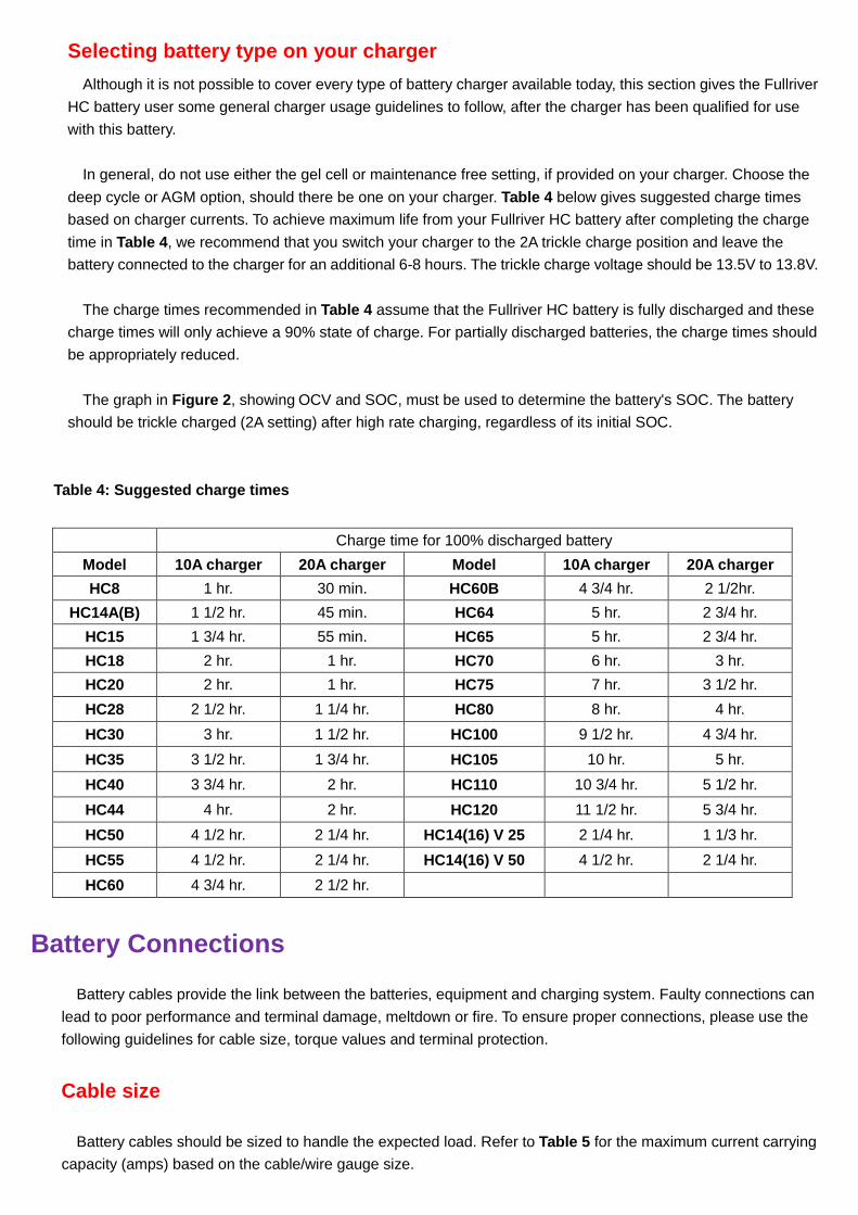
Selecting battery type on your charger
Although it is not possible to cover every type of battery charger available today, this section gives the Fullriver
HC battery user some general charger usage guidelines to follow, after the charger has been qualified for use
with this battery.
In general, do not use either the gel cell or maintenance free setting, if provided on your charger. Choose the
deep cycle or AGM option, should there be one on your charger. Table 4 below gives suggested charge times
based on charger currents. To achieve maximum life from your Fullriver HC battery after completing the charge
time in Table 4 , we recommend that you switch your charger to the 2A trickle charge position and leave the
battery connected to the charger for an additional 6-8 hours. The trickle charge voltage should be 13.5V to 13.8V.
The charge times recommended in Table 4 assume that the Fullriver HC battery is fully discharged and these
charge times will only achieve a 90% state of charge. For partially discharged batteries, the charge times should
be appropriately reduced.
The graph in Figure 2 , showing OCV and SOC, must be used to determine the battery's SOC. The battery
should be trickle charged (2A setting) after high rate charging, regardless of its initial SOC.
Table 4: Suggested charge times
Battery Connections
Battery cables provide the link between the batteries, equipment and charging system. Faulty connections can
lead to poor performance and terminal damage, meltdown or fire. To ensure proper connections, please use the
following guidelines for cable size, torque values and terminal protection.
Cable size
Battery cables should be sized to handle the expected load. Refer to Table 5 for the maximum current carrying
capacity (amps) based on the cable/wire gauge size.
Charge time for 100% discharged battery
Model 10A charger 20A charger Model 10A charger 20A charger
HC8 1 hr. 30 min. HC60B 4 3/4 hr. 2 1/2hr.
HC14A(B) 1 1/2 hr. 45 min. HC64 5 hr. 2 3/4 hr.
HC15 1 3/4 hr. 55 min. HC65 5 hr. 2 3/4 hr.
HC18 2 hr. 1 hr. HC70 6 hr. 3 hr.
HC20 2 hr. 1 hr. HC75 7 hr. 3 1/2 hr.
HC28 2 1/2 hr. 1 1/4 hr. HC80 8 hr. 4 hr.
HC30 3 hr. 1 1/2 hr. HC100 9 1/2 hr. 4 3/4 hr.
HC35 3 1/2 hr. 1 3/4 hr. HC105 10 hr. 5 hr.
HC40 3 3/4 hr. 2 hr. HC110 10 3/4 hr. 5 1/2 hr.
HC44 4 hr. 2 hr. HC120 11 1/2 hr. 5 3/4 hr.
HC50 4 1/2 hr. 2 1/4 hr. HC14(16) V 25 2 1/4 hr. 1 1/3 hr.
HC55 4 1/2 hr. 2 1/4 hr. HC14(16) V 50 4 1/2 hr. 2 1/4 hr.
HC60 4 3/4 hr. 2 1/2 hr.

Table 5: cable size
Wire Gauge Size(AWG) Ampacity (Amps)
14 25
12 30
10 40
8 55
6 75
4 95
2 130
1 150
1/0 170
2/0 265
4/0 360
Table values are for cable lengths less than 6 feet (1829 mm). In series/parallel battery banks, it is preferable for
all series cables to be the same length and all parallel cables to be the same length.
Torque Values
Terminal connections must be tightened using the correct torque values as defined in Table 6 . Over or
under-tightened connections can result in terminal breakage, over-heating and/or meltdown. Using the proper
torque value will provide optimum conductivity. Use a wrench with an insulated or rubber coated handle when
making terminal connections to avoid a short circuit. See diagram 1 for proper washer placement.
Table 6: Battery Terminal Torque Values
Terminal Type lbs-in Nm
M5 20~30 2.0~2.9
M6 50~70 5.6~7.9
M8 85~95 9.6~10.7
M6M-Stud 50~70 5.6~7.9
M10M-Stud 110~125 12.2~14
FR45(FR46) 70~90 7.9~10.1
TP07-AP / TP08-AP / AP 50~70 5.6~7.9
DT
AP 50~70 5.6~7.9
Stud 110~125 12.2~14
Note: Never place a washer between the mating surfaces of the terminals and cables, this will compromise
electrical transmission and increase resistance, resulting in extreme heat generation and probable terminal
melting. Corrosion can build up on terminals if they are not kept clean and dry. To prevent corrosion apply a thin
coat of petroleum jelly or terminal protector that can be purchased through your local battery dealer.
Ventilation
Gel and AGM batteries generally do not release gas but can if too much pressure builds up during charging. It is
critical to charge batteries in a properly ventilated area. For more assistance in calculating ventilation needs,
please contact your local FULLRIVER distributor or email [email protected] .

Connecting Batteries to Increase System Power
Series Connections
To increase voltage, connect batteries in series. This will not increase the system capacity. Refer to Diagram 1
for series connections.
Diagram 1:
Parallel Connections
To increase capacity, connect batteries in parallel. This will not increase the system voltage. Refer to Diagram 2
for parallel connections.
Diagram 2:
Series/Parallel Connections
To increase both voltage and capacity, connect additional batteries in series and parallel. Refer to Diagram 3 for
series/parallel connections.
Diagram 3:
Example:
Two HC110, 12V Batteries
Rated at 110 AH Connected in Series
System Voltage: 12V+12V=24V
System Capacity=110AH
Example:
Two HC110, 12V Batteries
Rated at 110AH Connected in parallel
System Voltage: 12V
System Capacity: 110AH+110AH=220AH
Example:
Two HC110, 12V Batteries
Rated at 110AH Connected in parallel
System Voltage: 12V+12V=24V
System Capacity: 110AH+110AH=220AH

Note: when connecting the batteries, free air space must be provided between each battery. The recommended
minimum space between batteries is 0.3 inches (8mm) to 0.6 inches (15mm). In all installations due consideration
must be given to adequate ventilation for the purposes of cooling.
Now that you have defined your battery needs refer to your Fullriver Brochure to select the model that meets
those specifications. Call your local Fullriver Battery Distributor and t hey would be happy to assist you in the final selection of your new Fullriver Batteries .
Battery orientation
The ideal placement of batteries is upright. AGM batteries can be placed on their side if necessary. It is preferred
that all the batteries within a pack be placed in the same orientation.
Battery Testing
Testing batteries can be complex and there are many application specific variables that cannot be considered in
one simple test. This section is a guide to help you determine the overall condition of your batteries. Contact your
local FULLRIVER distributor for assistance.
Test Preparation
1. Check that battery cables are in good condition. Replace any damaged or broken cables.
2. Check that all terminal connections are tightened to the proper torque specification.
3. Fully charge the batteries.
4. Let batteries rest for at least 8 hours once the charge is complete.
Open Circuit Voltage Test
1. Check and record open circuit voltage (OCV) of each battery.
2. If all the batteries are below 12.2V (12V battery), 14.3V (14V battery) or 16.3V (16V battery) the set is failed.
Replace the entire set of batteries. In this situation the battery set had either provided all its available energy or
was severely abused.
3. Otherwise any battery that is 0.5V lower than the highest battery voltage (12V battery), 0.60V lower than the
highest battery voltage (14V battery) or 0.65V lower than the highest battery voltage (16V battery) might have
failed. Make note of these batteries.
Note: all battery in a good set should be above 12. 7V (12V battery), 14.8V (14V battery), 16.9V (16V b attery) when fully charged after at least 8 hours of rest.
Discharge Test ( if you do not have a discharger proceed to Optinal Test )
1. Connect and start discharger.
2. Record minutes(runtime) when discharge is complete. Correct runtime minutes for battery temperature using the following formula: (valid between 24 ℃ to 32 ℃(75 ℉ to 90 ℉):
Mc=Mr(1-0.009(T-27)

where Mc is the corrected minutes, Mr is the minutes recorded and T is the temperature at the end of discharge
in ℃.
3. If the set runs more than 50% of its rated capacity, the batteries are good test is complete.
4. If the set runs less than 50% of its rated capacity, reconnct the discharger and while under the discharge load;
record the end of discharge voltage of each battey.
5. The batteries that are 0.5V(12V battery) lower than the higest end of discharge voltage should be noted.
6. If the set delivered less than 50% of its rated capacity, and the same batteries that were noted in Open Voltage
Test section., Step 3 were also the ones noted in section Discharge Test .,Step 5, those batteries are most likely
failed and should be replaced.
Otherwise,please contact your local FULLRIVER distributor or email [email protected] to review your data in
detail. Additional testing may be required depending on your specific application.
Optinal Test
After completing sections Test Prepartion and Open Circuit Voltage Test follow these steps:
1. Operate the vehicle/equipment until battery performance decreases.
2. Record voltages during and after operation.
3. Record time and distance of operation.
4. Provide the voltage , time and distance data to a FULLRIVER distributor or technical support at
5. This data will be analyzed in comparison to what is expected of the vehicle/eqipment.
Battery Replacement Instructions
Charge the set of batteries before replacing the failed ones, as long as is safe to do so, to make sure the good
batteries are fully charged.
If possible,replace failed batteries with good batteries aroud the same age frome another piece of equipment.
Try to aviod mixing new batteries in equipment with old batteries. Put all new batteries in the same piece of
equipment.
For battery replacement, follow the installation instructions in section Open Circuit Voltage Test .