A Bonnet and Fluid Jet Polishing Facility for Optics related to E-ELT Gabriele Vecchi...
14
A Bonnet and Fluid Jet Polishing Facility for Optics related to E-ELT Gabriele Vecchi INAF-Osservatorio Astronomico di Brera The outcome of the T-REX project – Sexten - July 2015 Review of the polishing methods Manufacturing optics related to E-ELT: MAORY and M1 (R&D) Results of the acceptance test Conclusions
-
Upload
linda-lloyd -
Category
Documents
-
view
216 -
download
2
Transcript of A Bonnet and Fluid Jet Polishing Facility for Optics related to E-ELT Gabriele Vecchi...

A Bonnet and Fluid Jet Polishing Facility for Optics related to E-ELT
Gabriele VecchiINAF-Osservatorio Astronomico di Brera
The outcome of the T-REX project – Sexten - July 2015
Review of the polishing methods
Manufacturing optics related to E-ELT: MAORY and M1 (R&D)
Results of the acceptance test
Conclusions

IRP Machine by Zeeko Ltd.The IRP is a 7 axis CNC optical polishing/forming machine capable of producing ultra-precise surfaces on a variety of materials and shapes.
~4meters
• IRP1200 model. Nominal max part size = 1200 mm.
• Three machines of this kind in Italy (two are in Media Lario).
• Footprint: 4,3m x 4,3m x 3m (including console, chiller and abrasive slurry unit).
• Load capacity = 500 Kg.
• Clean room ISO7, 49m2 area.
• Required temperature variations within 2°C over 24h.

Manufacturing Chain
ZEEKO POLISHING
Polishing with Zeeko machine brings the workpiece from mechanical to optical quality.
In traditional optical polishing the tool is forced against the workpiece in presence of abrasive fluid. There is no active control on tool-workpiece distance.
In CNC polishing the tool position is actively controlled to follow the surface of the workpiece.
Surface error vs time
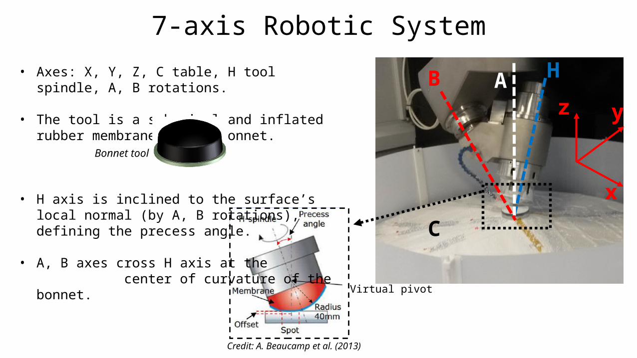
7-axis Robotic System
z y
x
C
HB A
Virtual pivot
Credit: A. Beaucamp et al. (2013)
• Axes: X, Y, Z, C table, H tool spindle, A, B rotations.
• The tool is a spherical and inflated rubber membrane, named bonnet.
• H axis is inclined to the surface’s local normal (by A, B rotations), defining the precess angle.
• A, B axes cross H axis at the center of curvature of the bonnet.
Bonnet tool
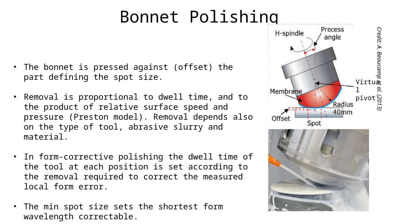
Bonnet Polishing
• The bonnet is pressed against (offset) the part defining the spot size.
• Removal is proportional to dwell time, and to the product of relative surface speed and pressure (Preston model). Removal depends also on the type of tool, abrasive slurry and material.
• In form-corrective polishing the dwell time of the tool at each position is set according to the removal required to correct the measured local form error.
• The min spot size sets the shortest form wavelength correctable.
Credit: A. Beaucamp et al. (2013)
Virtual pivot
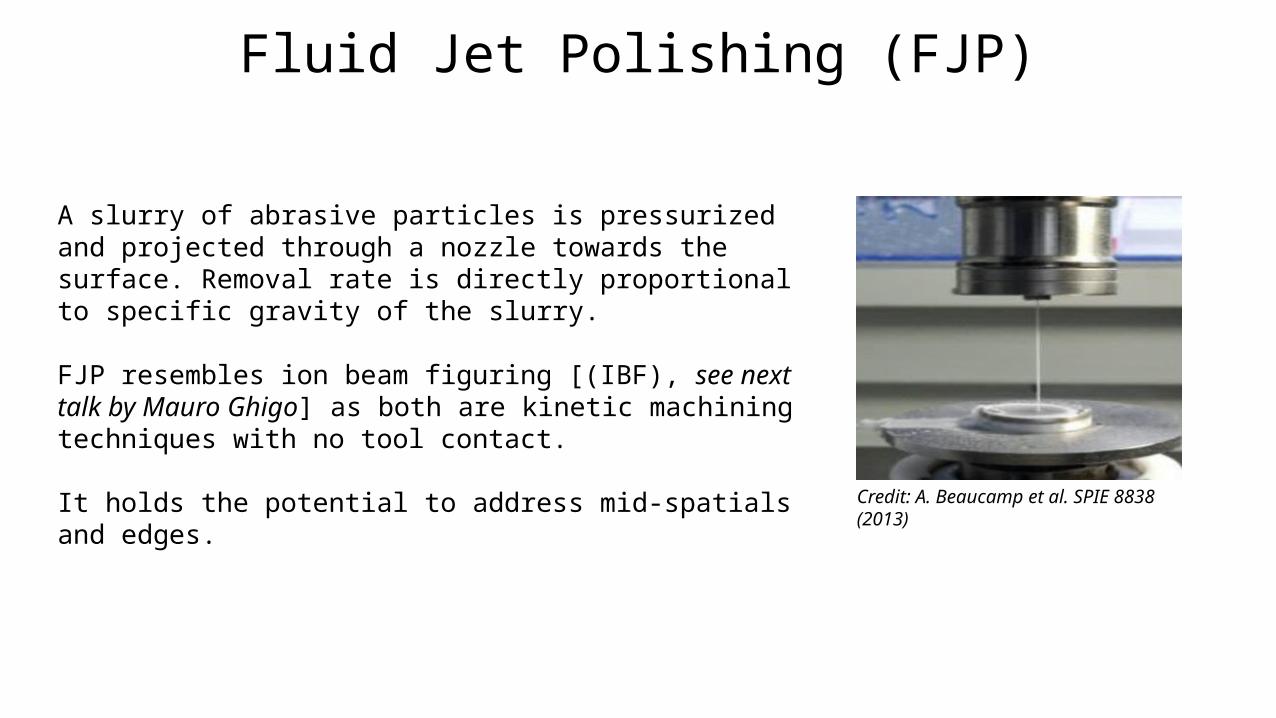
Fluid Jet Polishing (FJP)
A slurry of abrasive particles is pressurized and projected through a nozzle towards the surface. Removal rate is directly proportional to specific gravity of the slurry.
FJP resembles ion beam figuring [(IBF), see next talk by Mauro Ghigo] as both are kinetic machining techniques with no tool contact.
It holds the potential to address mid-spatials and edges.
Credit: A. Beaucamp et al. SPIE 8838 (2013)
Outline
Review of the polishing methods
Manufacturing optics related to E-ELT: MAORY and M1 (R&D) Results of the acceptance test
Conclusions

Manufacturing optics related to E-ELTThe UK consortium of Glyndŵr Innovations, University College London and Zeeko Ltd. has made segment prototype for M1-EELT fulfilling ESO’s specs (25 nm RMS). They applied bonnet polishing and pitch smoothing on a customized Zeeko 1600 machine. No final IBF.
C. Gray et al., Proc. of SPIE 88380K (2013) “Fast manufacturing of E-ELT mirror segments using CNC polishing”
Several challenges to overcome: Polishing near the edges Optimize the slurry management Accurate alignment and input data mapping Minimize/avoid mid spatials Cleanliness
Image credit: opTIC Glindwr University
Pitch smoothing tool
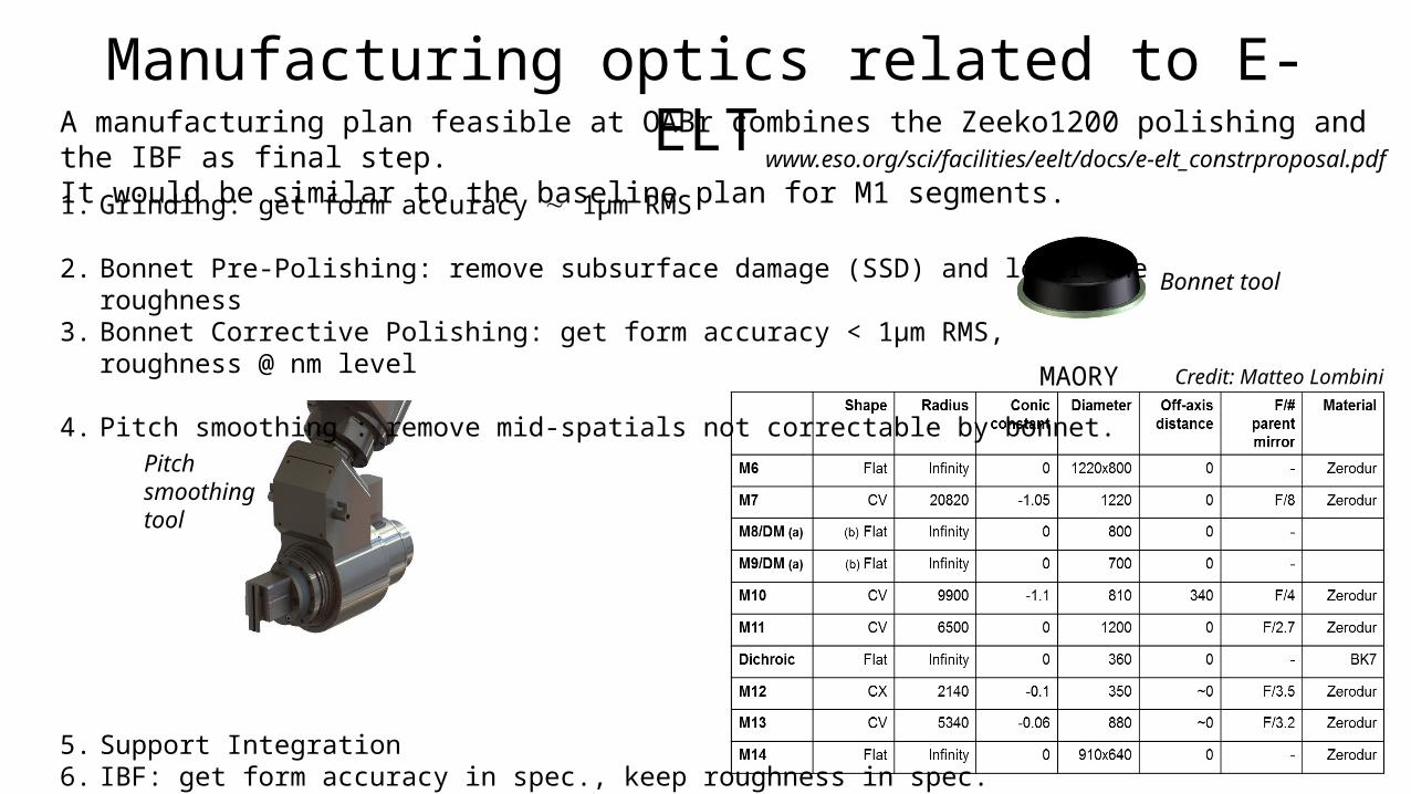
A manufacturing plan feasible at OABr combines the Zeeko1200 polishing and the IBF as final step. It would be similar to the baseline plan for M1 segments. www.eso.org/sci/facilities/eelt/docs/e-elt_constrproposal.pdf
1. Grinding: get form accuracy 1µm RMS
2. Bonnet Pre-Polishing: remove subsurface damage (SSD) and lower the roughness3. Bonnet Corrective Polishing: get form accuracy < 1µm RMS, roughness @ nm level
4. Pitch smoothing : remove mid-spatials not correctable by bonnet.
5. Support Integration6. IBF: get form accuracy in spec., keep roughness in spec.
Bonnet tool
Credit: Matteo LombiniMAORY
Manufacturing optics related to E-ELT

Outline
Review of the polishing methods
Manufacturing optics related to E-ELT: MAORY and M1 (R&D)
Results of the acceptance test Conclusions

Results of the Acceptance Test
1. Flat 100mm BK7 part, lapped (to a form error less than 2 µm)
mm
mm
mm
Error map after one pre-polishing run (144 min):1152 nm PV, 228 nm PV over 88mm clear aperture.
100 mm
• remove the SSD caused by the grinding phase • reduce the surface roughness (enabling
interferometry)• provide larger removal rate (than form corrective
polishing) to get quicker processing.
Pre-Polishing by Synchro-Spiral mode, intended to:
BK7 test sample

Results of the Acceptance Test2. 100mm flat BK7 part, previously pre-polished, Corrective Polishing
19 nm RMS reached after 5 runs (459 min).
• Form error maps acquired by interferometry• Goal: < /40 RMS (<16 nm RMS) over 88mm clear aperture
mm
mm
mm
Flat pre-polished sample, 1008 nm PV, 233 nm RMS.
mm
mm
mm
mm
mm
mm
After correction 1 632 nm PV, 110 nm RMS.
After correction 5 224 nm PV, 19 nm RMS.

Results of the Acceptance Test3. 100mm concave BK7 part, previously pre-polished, Corrective Polishing
• Starting conditions: 786 nm PV, 136 nm RMS
• After Correction 2: 104 nm PV, 12 nm RMS.
• Two corrective runs (180 min) brought the part within spec, < /40 RMS.
• Better convergence factor is
obtained once the removal rate has been made constant and known.
Images courtesy of P. Messelink, 2015
Conclusions
The outcome of the T-REX project – Sexten - July 2015
A Zeeko 1200 polishing/forming robotic machine has been implemented within the T-REX program at INAF-Brera Astronomical Observatory.
• Bonnet Polishing acceptance test has been performed successfully.• Fluid Jet Polishing acceptance test is being scheduled in short term.
Future activities:• Develop and practice the process on test pieces.• Establish the process aiming to MAORY optics and providing
technological development to E-ELT-M1. • Exploit the synergy between the two systems for polishing and IBF
hosted at Brera Observatory.