A BEE COLONY OPTIMIZATION BASED-FUZZY LOGIC-PID … · A BEE COLONY OPTIMIZATION BASED-FUZZY...
18
International Journal of Innovative Computing, Information and Control ICIC International c 2012 ISSN 1349-4198 Volume 8, Number 9, September 2012 pp. 6049–6066 A BEE COLONY OPTIMIZATION BASED-FUZZY LOGIC-PID CONTROL DESIGN OF ELECTROLYZER FOR MICROGRID STABILIZATION Theerawut Chaiyatham and Issarachai Ngamroo School of Electrical Engineering Faculty of Engineering King Mongkut’s Institute of Technology Ladkrabang Chalongkrung Road, Bangkok 10520, Thailand [email protected] Received May 2011; revised September 2011 Abstract. This paper proposes the optimal fuzzy logic based-proportional-integral-deri- vative (FLPID) controller design of the electrolyzer (EZ) by a bee colony optimization (BCO) for microgrid (MG) stabilization. The study MG system consists of wind power (WP), photovoltaic (PV), fuel cell (FC) equipped with EZ, diesel generator, and load. The intermittent power generations from WP and PV cause the severe power fluctuation in the MG. To alleviate power fluctuation, the EZ which is normally used to produce the hydrogen input for FC, can be applied. By control of active and reactive powers absorbed by EZ, the power fluctuation can be stabilized. The structure of active and reactive power controllers of EZ is the FLPID which consists of scale factors (SCs), membership func- tions (MFs), and control rules (CRs). Without trial and error, SCs, MFs, and CRs of the FLPID controller are automatically optimized by a BCO. Simulation study confirms that the proposed EZ with an optimal FLPID controller is much superior to the EZ with a conventional FLPID controller or an optimal PID controller in terms of stabilizing effect and robustness against various loading conditions and severe disturbances. Keywords: Electrolyzer, Microgrid, Fuzzy PID control, Bee colony optimization 1. Introduction. Nowadays, the microgrid (MG) is expected as the smart electrical power management for rural and isolated areas that cannot access to the main power grid due to the restriction of installation costs of transmission lines, right of way difficulties, social, and environmental impacts [1]. The MG is the cluster of the distributed generation with renewable energy sources and/or conventional generating units and loads [2]. At present, there are many MG projects around the world such as Kythnos Island MG in Greece [2], Aichi, Kyotango and Hachinohe MG projects in Japan [3], and the Consortium for Electric Reliability Technology Solutions (CERTS) project in the United States [4], etc. Generally, renewable energy sources such as wind power (WP), photovoltaic (PV), fuel cell (FC) with electrolyzer (EZ), are usually installed in the MG, since these sources are inexhaustible, environmental friendly, clean, and no CO 2 emission [5]. These renewable energy sources are often operated with the conventional electricity generations such as diesel generator (DG), and gas turbine. Nevertheless, the solar and wind energy are intermittent in nature. The power generation from WP and PV is variable [6]. This causes the power unbalance in generation and load [7], and results in the severe power fluctuation in the MG [8-10]. To suppress the power fluctuation, several methods have been proposed in previous works [11-14]. Recent advancement in the EZ equipped with an FC has opened up options for using hydrogen as an energy storage. In addition to a 6049
Transcript of A BEE COLONY OPTIMIZATION BASED-FUZZY LOGIC-PID … · A BEE COLONY OPTIMIZATION BASED-FUZZY...
International Journal of InnovativeComputing, Information and Control ICIC International c©2012 ISSN 1349-4198Volume 8, Number 9, September 2012 pp. 6049–6066
A BEE COLONY OPTIMIZATION BASED-FUZZY LOGIC-PIDCONTROL DESIGN OF ELECTROLYZER FOR
MICROGRID STABILIZATION
Theerawut Chaiyatham and Issarachai Ngamroo
School of Electrical EngineeringFaculty of Engineering
King Mongkut’s Institute of Technology LadkrabangChalongkrung Road, Bangkok 10520, Thailand
Received May 2011; revised September 2011
Abstract. This paper proposes the optimal fuzzy logic based-proportional-integral-deri-vative (FLPID) controller design of the electrolyzer (EZ) by a bee colony optimization(BCO) for microgrid (MG) stabilization. The study MG system consists of wind power(WP), photovoltaic (PV), fuel cell (FC) equipped with EZ, diesel generator, and load.The intermittent power generations from WP and PV cause the severe power fluctuationin the MG. To alleviate power fluctuation, the EZ which is normally used to produce thehydrogen input for FC, can be applied. By control of active and reactive powers absorbedby EZ, the power fluctuation can be stabilized. The structure of active and reactive powercontrollers of EZ is the FLPID which consists of scale factors (SCs), membership func-tions (MFs), and control rules (CRs). Without trial and error, SCs, MFs, and CRs ofthe FLPID controller are automatically optimized by a BCO. Simulation study confirmsthat the proposed EZ with an optimal FLPID controller is much superior to the EZ witha conventional FLPID controller or an optimal PID controller in terms of stabilizingeffect and robustness against various loading conditions and severe disturbances.Keywords: Electrolyzer, Microgrid, Fuzzy PID control, Bee colony optimization
1. Introduction. Nowadays, the microgrid (MG) is expected as the smart electricalpower management for rural and isolated areas that cannot access to the main power griddue to the restriction of installation costs of transmission lines, right of way difficulties,social, and environmental impacts [1]. The MG is the cluster of the distributed generationwith renewable energy sources and/or conventional generating units and loads [2]. Atpresent, there are many MG projects around the world such as Kythnos Island MG inGreece [2], Aichi, Kyotango and Hachinohe MG projects in Japan [3], and the Consortiumfor Electric Reliability Technology Solutions (CERTS) project in the United States [4],etc.
Generally, renewable energy sources such as wind power (WP), photovoltaic (PV), fuelcell (FC) with electrolyzer (EZ), are usually installed in the MG, since these sources areinexhaustible, environmental friendly, clean, and no CO2 emission [5]. These renewableenergy sources are often operated with the conventional electricity generations such asdiesel generator (DG), and gas turbine. Nevertheless, the solar and wind energy areintermittent in nature. The power generation from WP and PV is variable [6]. Thiscauses the power unbalance in generation and load [7], and results in the severe powerfluctuation in the MG [8-10]. To suppress the power fluctuation, several methods havebeen proposed in previous works [11-14]. Recent advancement in the EZ equipped withan FC has opened up options for using hydrogen as an energy storage. In addition to a
6049
6050 T. CHAIYATHAM AND I. NGAMROO
hydrogen production for an FC input, the EZ can be used as the controllable load [15,16].Moreover, the power absorbed by EZ can be rapidly controlled to compensate for powerfluctuation in the MG [17].In recent years, many works have been conducted on control system stabilization. How-
ever, all those control design methods require the exact mathematical model of the controlsystems which may not be available in practice. On the other hand, a fuzzy logic controlhas been successfully employed for solving many nonlinear control problems. Withoutexact mathematical model of the control system, the fuzzy controller can be designed. In[18], the fuzzy decentralized state feedback and observer-based decentralized output feed-back controllers for a class of continuous nonlinear interconnected systems with time-delayand the modelling error have been applied. In [19], the sliding mode controller with fuzzylogic has been used for the heading control of the submersible vehicle. In [20], the methodof fuzzy control systems for trailers driven by multiple motors in side slipways to haul outships has been presented. In [21], the fuzzy logic controller with interval-valued inferencemechanism has been applied for the control of distributed parameter system. Besides, thefuzzy logic based-proportional-integral-derivative (FLPID) controller has been proposedin [22]. In these works, nevertheless, the selection of scale factors (SF), membership func-tions (MF), and control rules (CR) of the FLPID controller is still the inevitable problemand depends on the designer’s experience.To overcome this problem, this paper proposes the new optimal FLPID controller de-
sign of EZ for alleviation of power fluctuation in the MG with hybrid power generationssuch as WP, PV, FC with EZ, and DG. The intermittent power generations from WPand PV result in severe power fluctuation in the MG. With the fast response of EZ, thepower absorbed by an EZ can be rapidly controlled to compensate for power fluctua-tion. To achieve the optimal SF, MF, and CR of the FLPID, this paper applies a beecolony optimization (BCO) [23] to automatically tune these parameters of the FLPID.Simulation study is carried out in the nonlinear MG model. The proposed EZ with anoptimal FLPID controller not only shows superior stabilizing effect than the EZ with aconventional FLPID or optimal PID controller, but also provides high robustness undervarious operating conditions and large disturbances.
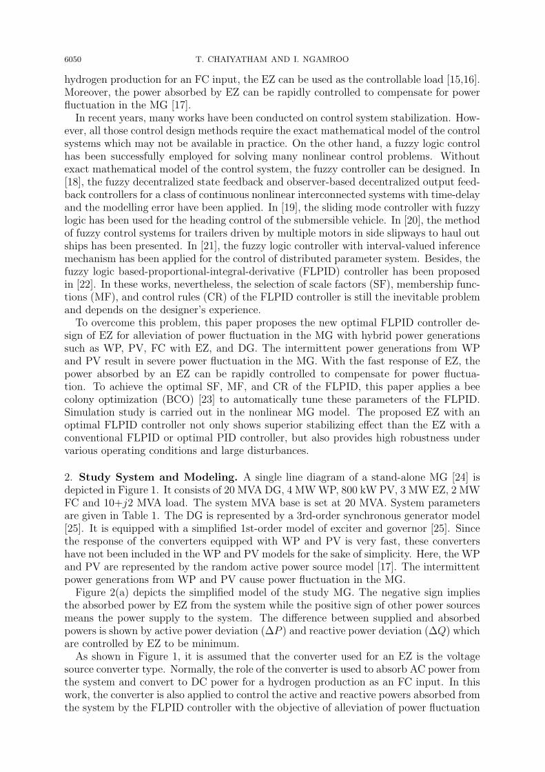
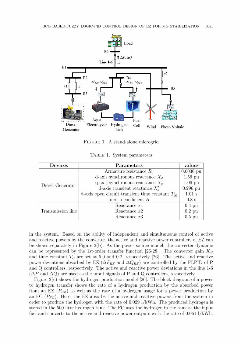
2. Study System and Modeling. A single line diagram of a stand-alone MG [24] isdepicted in Figure 1. It consists of 20 MVA DG, 4 MWWP, 800 kW PV, 3 MW EZ, 2 MWFC and 10+j2 MVA load. The system MVA base is set at 20 MVA. System parametersare given in Table 1. The DG is represented by a 3rd-order synchronous generator model[25]. It is equipped with a simplified 1st-order model of exciter and governor [25]. Sincethe response of the converters equipped with WP and PV is very fast, these convertershave not been included in the WP and PV models for the sake of simplicity. Here, the WPand PV are represented by the random active power source model [17]. The intermittentpower generations from WP and PV cause power fluctuation in the MG.Figure 2(a) depicts the simplified model of the study MG. The negative sign implies
the absorbed power by EZ from the system while the positive sign of other power sourcesmeans the power supply to the system. The difference between supplied and absorbedpowers is shown by active power deviation (∆P ) and reactive power deviation (∆Q) whichare controlled by EZ to be minimum.As shown in Figure 1, it is assumed that the converter used for an EZ is the voltage
source converter type. Normally, the role of the converter is used to absorb AC power fromthe system and convert to DC power for a hydrogen production as an FC input. In thiswork, the converter is also applied to control the active and reactive powers absorbed fromthe system by the FLPID controller with the objective of alleviation of power fluctuation
BCO BASED-FUZZY LOGIC-PID CONTROL DESIGN OF EZ FOR MG STABILIZATION 6051
Figure 1. A stand-alone microgrid
Table 1. System parameters
Devices Parameters values
Diesel Generator
Armature resistance Ra 0.0036 pud-axis synchronous reactance Xd 1.56 puq-axis synchronous reactance Xq 1.06 pud-axis transient reactance X ′
d 0.296 pud-axis open circuit transient time constant T ′
d0 1.01 sInertia coefficient H 0.8 s
Transmission lineReactance x1 0.4 puReactance x2 0.2 puReactance x3 0.5 pu
in the system. Based on the ability of independent and simultaneous control of activeand reactive powers by the converter, the active and reactive power controllers of EZ canbe shown separately in Figure 2(b). As the power source model, the converter dynamiccan be represented by the 1st-order transfer function [26-28]. The converter gain KE
and time constant TE are set at 5.0 and 0.2, respectively [26]. The active and reactivepower deviations absorbed by EZ (∆PEZ and ∆QEZ) are controlled by the FLPID of Pand Q controllers, respectively. The active and reactive power deviations in the line 1-6(∆P and ∆Q) are used as the input signals of P and Q controllers, respectively.
Figure 2(c) shows the hydrogen production model [26]. The block diagram of a powerto hydrogen transfer shows the rate of a hydrogen production by the absorbed powerfrom an EZ (PEZ) as well as the rate of a hydrogen usage for a power production byan FC (PFC). Here, the EZ absorbs the active and reactive powers from the system inorder to produce the hydrogen with the rate of 0.029 l/kWh. The produced hydrogen isstored in the 500 litre hydrogen tank. The FC uses the hydrogen in the tank as the inputfuel and converts to the active and reactive power outputs with the rate of 0.061 l/kWh.
6052 T. CHAIYATHAM AND I. NGAMROO
(a) Simplified diagram
(b) EZ model with P and Q controllers
(c) Hydrogen production model
(d) Relation of the remaining hydrogen inthe tank and the generating rate of FC
(e) FC model
Figure 2. MG modelling

BCO BASED-FUZZY LOGIC-PID CONTROL DESIGN OF EZ FOR MG STABILIZATION 6053
The difference between a hydrogen production by an EZ and a hydrogen usage by an FCbecomes the remaining hydrogen in the tank.
In this study, the operating method of FC generators has two limitations. These lim-itations are very important in reduction of a start-up and a shutdown of FC generatorssince a voltage of FC drops due to its start-up and shutdown operations [26]. These twolimitations are given as follows.
i If the remaining amount of the hydrogen drops below 10% of a hydrogen tank capacity,the FC stops. The FC continues to stop until the capacity of the hydrogen reaches50%.
ii The generating rate of the FC (ρ) varies with the remaining fuel in the hydrogen tank.The relation between the remaining fuel in hydrogen tank and the generating rate isshown in Figure 2(d) [26].
For the FC model, it is represented by the constant power source model as shown inFigure 2(e). The active and reactive power output commands (PFC and QFC) of FC arekept constant at 0.05 pu and 0 pu, respectively. From the limitation (ii), the actualgenerating power of FC (PFC and QFC) is represented by the product of the generatingrate and the output command of FC as
PFC = ρP FC
QFC = ρQFC
(1)
3. Proposed Optimized FLPID Controller. The main idea of fuzzy logic system wasintroduced by Zadeh in 1965 [29], and first applied to control theory in 1974 by Mamdani[30]. Based on these works, the fuzzy controllers have successfully been employed forvarious applications [31-33]. One of most popular type of fuzzy logic control is the FLPIDcontroller as shown in Figure 3, because the FLPID is able to eliminate steady state errorand good performance during the transient state [34].
Figure 3 shows the proposed FLPID for P-Q controllers of EZ. The input signal e isthe active power deviation in the line 1-6 for P controller or reactive power deviation inthe line 1-6 for Q controller. The output signal of FLPID controller is given by
u = αy + β
∫y dt (2)
It has been shown in [22] that for the product – sum crisp type fuzzy controller, therelation between the input and the output variables of the fuzzy logic controller can begiven as
y = A+BE +DE ′ (3)
where E = Kee and E ′ = Kde′. Therefore, from (2) and (3), the controller output is
obtained as
u = αA+ βAt+ αKeBe+ βKdDe+ βKeB
∫e dt+ αKdDe• (4)
Figure 3. Block diagram of FLPID controller

6054 T. CHAIYATHAM AND I. NGAMROO
Thus, the equivalent control components of the FLPID type are obtained as follows:
• Proportional gain: αKeP + βKdD• Integral gain: βKeP• Derivative gain: αKdD
In case of the design of FLPID controller, there are four tuning parameters of SFsi.e., Ke, Kd, β and α. Besides, there are many tuning parameters of MFs and CRs.Here, consider two shapes of MF, i.e., triangular and trapezoidal memberships which areshown in Figure 4. A triangular membership is defined by three parameters, i.e., left base(L), centre (C), and right base (R). For a trapezoidal membership, it is defined by fourparameters, i.e., left base (L), centre 1 (C1), centre 2 (C2), and right base (R). Each MF iscomposed of two trapezoidal memberships and five triangular memberships. Accordingly,it has 23 (4 + 3 + 3 + 3 + 3 + 3 + 4 = 23) tuning parameters. The fuzzy logic controllerhas two-inputs and one-output. Therefore, there are 69 (3× 23 = 69) tuning parameters.
Figure 4. The shape of membership functions
Figure 5. Structure of control rules for fuzzy logic controller
The CRs for two-inputs and one-output fuzzy logic controller is represented by n rowsand 5 columns matrix as shown in Figure 5. When this idea is applied to the fuzzy logictoolbox, n is the total number of relationships between all possible input pairs (for 7MFs, n = 72 = 49). The third column in the control rule table is the linguistic variableoutputs. Generally, it is represented by a numeric symbol. The universe of discourse inthis study contains seven memberships. Consequently, the control rules are representedby seven numbers (1to 7), 1: LN, 2: MN, 3: SN, 4: Z, 5: SP, 6: MP, and 7: LP. Note
BCO BASED-FUZZY LOGIC-PID CONTROL DESIGN OF EZ FOR MG STABILIZATION 6055
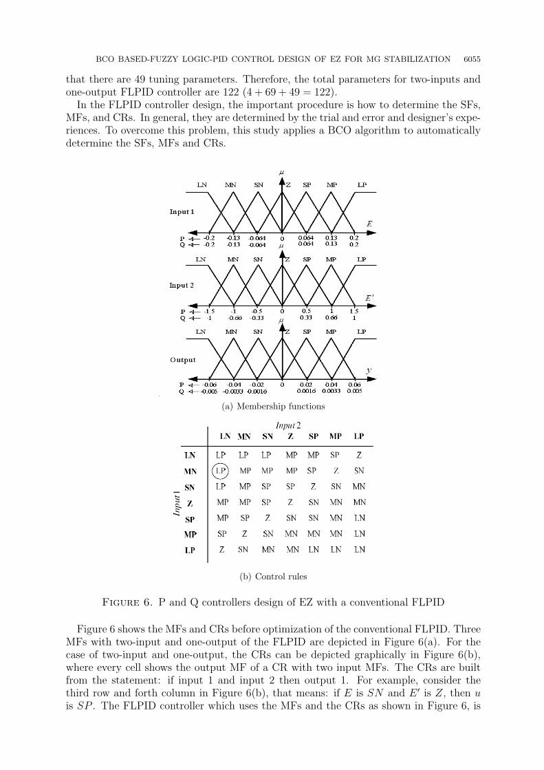
that there are 49 tuning parameters. Therefore, the total parameters for two-inputs andone-output FLPID controller are 122 (4 + 69 + 49 = 122).
In the FLPID controller design, the important procedure is how to determine the SFs,MFs, and CRs. In general, they are determined by the trial and error and designer’s expe-riences. To overcome this problem, this study applies a BCO algorithm to automaticallydetermine the SFs, MFs and CRs.
(a) Membership functions
(b) Control rules
Figure 6. P and Q controllers design of EZ with a conventional FLPID
Figure 6 shows the MFs and CRs before optimization of the conventional FLPID. ThreeMFs with two-input and one-output of the FLPID are depicted in Figure 6(a). For thecase of two-input and one-output, the CRs can be depicted graphically in Figure 6(b),where every cell shows the output MF of a CR with two input MFs. The CRs are builtfrom the statement: if input 1 and input 2 then output 1. For example, consider thethird row and forth column in Figure 6(b), that means: if E is SN and E ′ is Z, then uis SP . The FLPID controller which uses the MFs and the CRs as shown in Figure 6, is

6056 T. CHAIYATHAM AND I. NGAMROO
referred to as the “Conventional FLPID controller”. Note that only the SFs are tunedfor conventional FLPID. On the other hand, for the proposed controller which is referredto as the “Optimal FLPID controller”, the SFs, MFs, and CRs are automatically tuned.The optimization problem for optimal PID, conventional FLPID and optimal FLPID
controllers is formulated based on the minimization of the integral absolute error (IAE)of the line power deviations as,
Minimize IAE =
t∫0
(|∆P (t)|+ |∆Q(t)|) dt (5)
This optimization problem is solved by BCO.
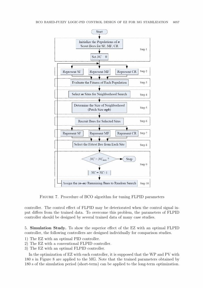
4. Bee Colony Optimization. The BCO algorithm mimics the food foraging behaviourof swarms of honey bees [23]. Honey bees use several mechanisms like waggle dance tooptimally locate food sources and search new ones. This makes them a good candidate fordeveloping new intelligent search algorithms. It is a very simple, robust and populationbased stochastic optimization algorithm. The procedure of the BCO algorithm for tuningFLPID parameters as shown in Figure 7 can be described as below:
Step 1: Generate randomly the initial populations of n scout bees for the parameters ofSF, MF, and CR. These initial populations must be feasible candidate solutionsthat satisfy the constraints. Set NC = 0.
Step 2: Represent the value of SF, MF, and CR from each population.Step 3: Evaluate the fitness value of the initial populations by (5).Step 4: Select m best sites for neighborhood search. Separated the m best sites to two
groups, the first group has e best sites and another group has m− e best sites.Step 5: Determine the size of neighborhood search of each best size (patch size, ngh).Step 6: Recruit bees of ne employed bees for selected sites (more bees for the best e
sites).Step 7: Represent the value of SF, MF, and CR from each employed bee.Step 8: Select the fittest bees from each patch.Step 9: Check the stopping criterion. If satisfied, terminate the search, else NC =
NC + 1.Step 10: Assign the n−m remaining bees to random search. Go to Step 2.
where ns is number of scout bee, NC is number of iteration, m is number of sites selectedfor neighborhood search, e is number of best “elite” sites out of m selected sites and neis number of employed bee.The motivation of the practical use of the theoretic results obtained from the proposed
method is the automatic optimization of SFs, MFs, and CRs for the FLPID controller byBCO. Without trial and error and designer’s experience, the optimal FLPID controllercan be automatically tuned. In addition, the proposed method can be practically appliedin industrial systems such as a fuzzy control design in a tunnel lighting system [35], a fuzzycontrol design in a wire transport system of wire electrical discharge machining machine[36], a fuzzy control design in a fuel-cell hybrid tramway [37], and a fuzzy control designfor a gas engine driven heat pump [38] etc. The application of the proposed method tothese practical systems not only considerably simplifies the fuzzy control design, but alsosignificantly enhances the control effect.However, the deficiency of the proposed technique is that the trained parameters ob-
tained from some case studies cannot guarantee the control effect of the designed FLPID
BCO BASED-FUZZY LOGIC-PID CONTROL DESIGN OF EZ FOR MG STABILIZATION 6057
Figure 7. Procedure of BCO algorithm for tuning FLPID parameters
controller. The control effect of FLPID may be deteriorated when the control signal in-put differs from the trained data. To overcome this problem, the parameters of FLPIDcontroller should be designed by several trained data of many case studies.
5. Simulation Study. To show the superior effect of the EZ with an optimal FLPIDcontroller, the following controllers are designed individually for comparison studies.
1) The EZ with an optimal PID controller.2) The EZ with a conventional FLPID controller.3) The EZ with an optimal FLPID controller.
In the optimization of EZ with each controller, it is supposed that the WP and PV with180 s in Figure 8 are applied to the MG. Note that the trained parameters obtained by180 s of the simulation period (short-term) can be applied to the long-term optimization.

6058 T. CHAIYATHAM AND I. NGAMROO
Although the optimization with long-term provides better result than that with short-term, it takes longer time in the optimization. If the data of short-term and long-termare not much different, the short-term data is preferable. Here, the constant parametersin BCO are set as follows: ns = 100, ne = 10, m = 10, e = 4, ngh = 30% and NC = 100.
Figure 8. WP and PV outputs
Figure 9. Convergence curves
As a result, the convergence curves of the EZ with an optimal PID, the EZ with aconventional FLPID, and the EZ with an optimal FLPID are shown in Figure 9. Theystart at the different initial values and gradually decrease to the minimum values. Besides,the MF and CR of P and Q controllers of EZ are delineated in Figures 10 and 11,

BCO BASED-FUZZY LOGIC-PID CONTROL DESIGN OF EZ FOR MG STABILIZATION 6059
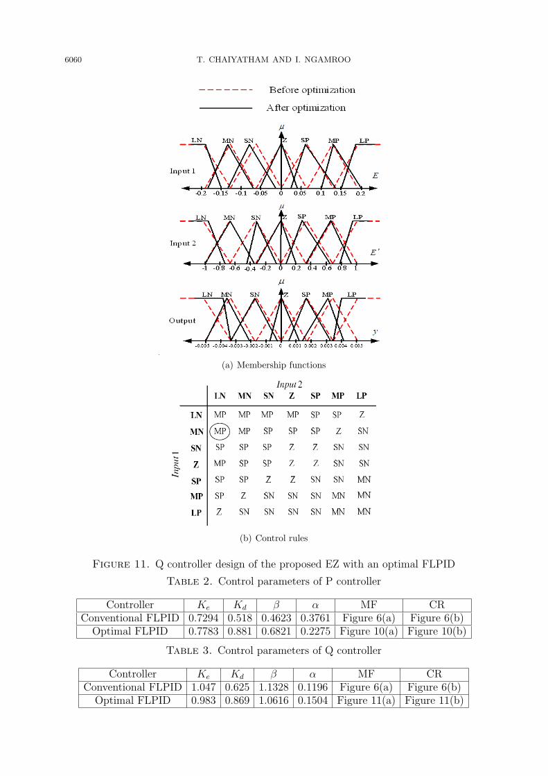
respectively. For example of the MF before and after optimizations in Figure 10(a), theleft base value, the centre value, and the right base value of the optimized membershipZ have been moved from −0.064, 0, 0.064 to −0.035, 0, 0.046, respectively. For exampleof the CR before and after optimizations, the encircled rule “LP” before optimization inFigure 6(b) has been changed to the encircled “MP” after optimization in Figures 10(b)and 11(b). The optimized parameters of P and Q controllers of EZ can be automaticallyachieved as in Tables 2 and 3, respectively. Besides, the PID control parameters of EZare obtained by the same proposed method as shown in Table 4.
(a) Membership functions
(b) Control rules
Figure 10. P controller design of the proposed EZ with an optimal FLPID
Nonlinear simulations are carried out for four case studies.Case 1: The MG is operated under power generations from WP and PV in Figure 8.
6060 T. CHAIYATHAM AND I. NGAMROO
(a) Membership functions
(b) Control rules
Figure 11. Q controller design of the proposed EZ with an optimal FLPID
Table 2. Control parameters of P controller
Controller Ke Kd β α MF CRConventional FLPID 0.7294 0.518 0.4623 0.3761 Figure 6(a) Figure 6(b)
Optimal FLPID 0.7783 0.881 0.6821 0.2275 Figure 10(a) Figure 10(b)
Table 3. Control parameters of Q controller
Controller Ke Kd β α MF CRConventional FLPID 1.047 0.625 1.1328 0.1196 Figure 6(a) Figure 6(b)
Optimal FLPID 0.983 0.869 1.0616 0.1504 Figure 11(a) Figure 11(b)

BCO BASED-FUZZY LOGIC-PID CONTROL DESIGN OF EZ FOR MG STABILIZATION 6061
Table 4. PID control parameters of P and Q controllers
Controller KP KI KD
P Controller 0.357 0.056 0.052Q Controller 0.195 0.042 0.049
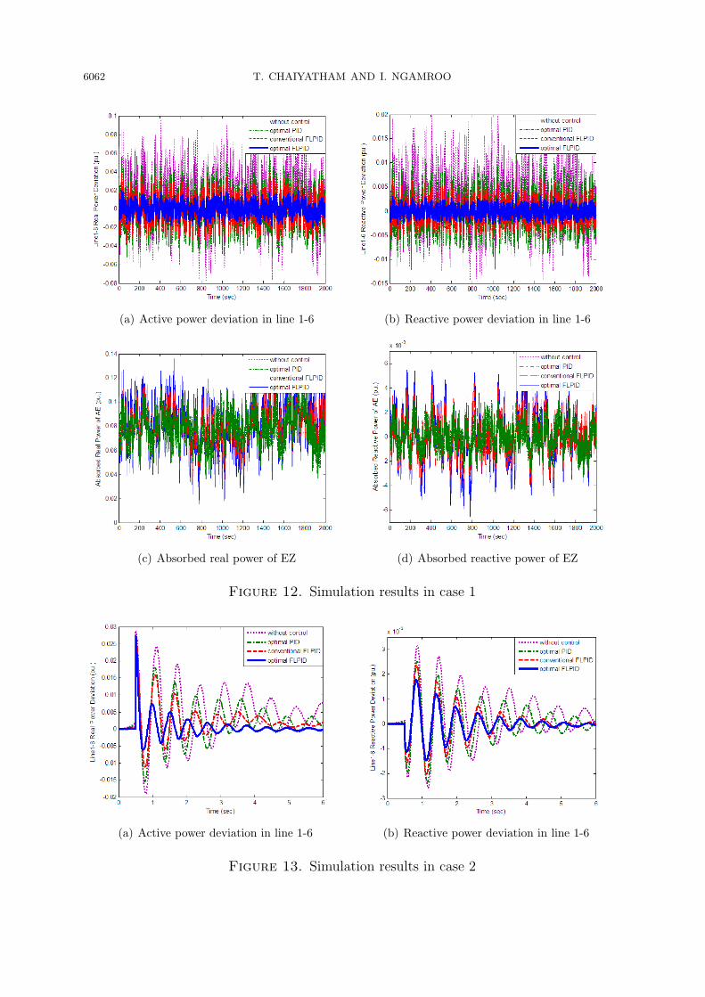
Simulation results for 2,000 s are depicted in Figure 12. As shown in Figures 12(a) and12(b), without EZ controller, the active and reactive power flows in the lines 1-6 severelyfluctuate. On the other hand, the EZs with an optimal PID, conventional FLPID andoptimal PID are able to alleviate the power fluctuation effectively. Nevertheless, the EZwith an optimal FLPID provides better damping effect than EZ with conventional FLPIDor optimal PID. The absorbed active and reactive powers of EZ are demonstrated in Fig-ures 12(c) and 12(d), respectively. The power absorbed by the EZ with an optimal FLPIDis higher than that of the EZ with conventional FLPID or optimal PID. Accordingly, theactive and reactive power fluctuations in the line 1-6 in case of the EZ with an optimalFLPID are lower than those of the EZ with conventional FLPID or optimal PID.
Case 2: Assume that the power generations from WP and PV in Figure 8 decrease by50%. At t = 0.5 s, the active power of load suddenly increases from 0.6 pu to 0.8 pu.
Simulation results of active and reactive power deviations in the line 1-6 are shownin Figures 13(a) and 13(b), respectively. In comparison to the EZ with a conventionalFLPID or optimal PID, the EZ with an optimal FLPID shows better stabilizing effect.
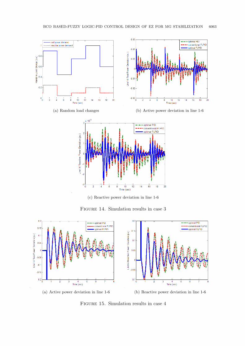
Case 3: Assume that the power generations from WP and PV in Figure 8 decrease by50% while the random step load occurs as shown in Figure 14(a).
Simulation results of active and reactive power fluctuations in the line 1-6 are shownin Figures 14(b) and 14(c), respectively. The EZ with a conventional FLPID is verysensitive to the disturbances. The power oscillations are higher and very severe. On thecontrary, the proposed EZ with an optimal FLPID is robustly capable of damping thepower oscillations.
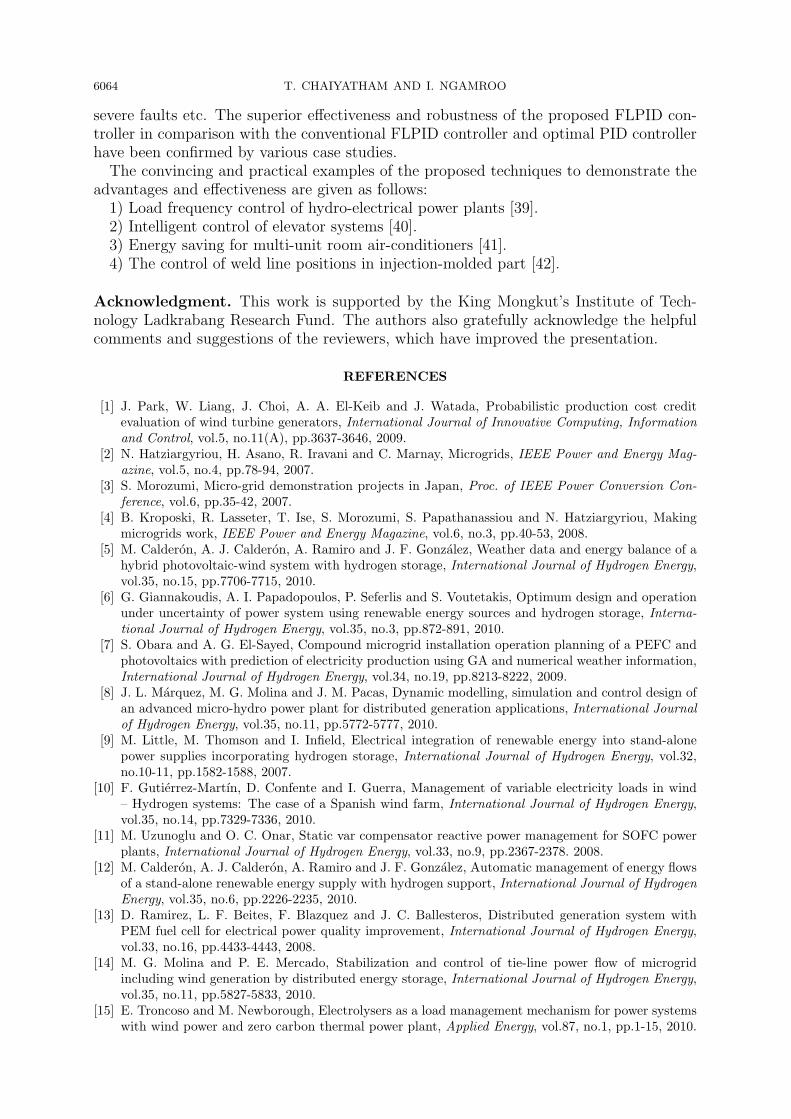
Case 4: Assume that the power generations from WP and PV in Figure 8 decreaseby 35%. The three phase fault to ground occurs at t = 0.5 s for 70 ms and is clearednaturally.
Simulation results of active and reactive power fluctuations in the line 1-6 are depictedin Figure 15(a) and 15(b), respectively. It can be observed that the stabilizing effect ofthe EZ with a conventional FLPID is considerably deteriorated by the three-phase fault.The damping of power oscillation is very poor. On the other hand, the proposed EZ withan optimal FLPID can tolerate this severe disturbance. It is able to damp out poweroscillations robustly.
6. Conclusion. The BCO-based optimal FLPID control design of EZ for stabilizationof power fluctuation in a stand-alone MG has been presented in this paper. The activeand reactive power controllers of EZ are optimized by the proposed design.
The unique features and the main advantages which make the proposed BCO basedFLPID superior over other fuzzy control approaches can be summarized as follows.
1) Without trial and error, all adjusting parameters of the FLPID controller, i.e. SCs,MFs, and CRs are automatically and simultaneously optimized by a BCO. As a result,the optimal FLPID controller can be guaranteed.
2) The designed FLPID controller is very effective and robust because it can deal withvarious disturbances and system uncertainties such as various loading conditions and
6062 T. CHAIYATHAM AND I. NGAMROO
(a) Active power deviation in line 1-6 (b) Reactive power deviation in line 1-6
(c) Absorbed real power of EZ (d) Absorbed reactive power of EZ
Figure 12. Simulation results in case 1
(a) Active power deviation in line 1-6 (b) Reactive power deviation in line 1-6
Figure 13. Simulation results in case 2
BCO BASED-FUZZY LOGIC-PID CONTROL DESIGN OF EZ FOR MG STABILIZATION 6063
(a) Random load changes (b) Active power deviation in line 1-6
(c) Reactive power deviation in line 1-6
Figure 14. Simulation results in case 3
(a) Active power deviation in line 1-6 (b) Reactive power deviation in line 1-6
Figure 15. Simulation results in case 4
6064 T. CHAIYATHAM AND I. NGAMROO
severe faults etc. The superior effectiveness and robustness of the proposed FLPID con-troller in comparison with the conventional FLPID controller and optimal PID controllerhave been confirmed by various case studies.The convincing and practical examples of the proposed techniques to demonstrate the
advantages and effectiveness are given as follows:1) Load frequency control of hydro-electrical power plants [39].2) Intelligent control of elevator systems [40].3) Energy saving for multi-unit room air-conditioners [41].4) The control of weld line positions in injection-molded part [42].
Acknowledgment. This work is supported by the King Mongkut’s Institute of Tech-nology Ladkrabang Research Fund. The authors also gratefully acknowledge the helpfulcomments and suggestions of the reviewers, which have improved the presentation.
REFERENCES
[1] J. Park, W. Liang, J. Choi, A. A. El-Keib and J. Watada, Probabilistic production cost creditevaluation of wind turbine generators, International Journal of Innovative Computing, Informationand Control, vol.5, no.11(A), pp.3637-3646, 2009.
[2] N. Hatziargyriou, H. Asano, R. Iravani and C. Marnay, Microgrids, IEEE Power and Energy Mag-azine, vol.5, no.4, pp.78-94, 2007.
[3] S. Morozumi, Micro-grid demonstration projects in Japan, Proc. of IEEE Power Conversion Con-ference, vol.6, pp.35-42, 2007.
[4] B. Kroposki, R. Lasseter, T. Ise, S. Morozumi, S. Papathanassiou and N. Hatziargyriou, Makingmicrogrids work, IEEE Power and Energy Magazine, vol.6, no.3, pp.40-53, 2008.
[5] M. Calderon, A. J. Calderon, A. Ramiro and J. F. Gonzalez, Weather data and energy balance of ahybrid photovoltaic-wind system with hydrogen storage, International Journal of Hydrogen Energy,vol.35, no.15, pp.7706-7715, 2010.
[6] G. Giannakoudis, A. I. Papadopoulos, P. Seferlis and S. Voutetakis, Optimum design and operationunder uncertainty of power system using renewable energy sources and hydrogen storage, Interna-tional Journal of Hydrogen Energy, vol.35, no.3, pp.872-891, 2010.
[7] S. Obara and A. G. El-Sayed, Compound microgrid installation operation planning of a PEFC andphotovoltaics with prediction of electricity production using GA and numerical weather information,International Journal of Hydrogen Energy, vol.34, no.19, pp.8213-8222, 2009.
[8] J. L. Marquez, M. G. Molina and J. M. Pacas, Dynamic modelling, simulation and control design ofan advanced micro-hydro power plant for distributed generation applications, International Journalof Hydrogen Energy, vol.35, no.11, pp.5772-5777, 2010.
[9] M. Little, M. Thomson and I. Infield, Electrical integration of renewable energy into stand-alonepower supplies incorporating hydrogen storage, International Journal of Hydrogen Energy, vol.32,no.10-11, pp.1582-1588, 2007.
[10] F. Gutierrez-Martın, D. Confente and I. Guerra, Management of variable electricity loads in wind– Hydrogen systems: The case of a Spanish wind farm, International Journal of Hydrogen Energy,vol.35, no.14, pp.7329-7336, 2010.
[11] M. Uzunoglu and O. C. Onar, Static var compensator reactive power management for SOFC powerplants, International Journal of Hydrogen Energy, vol.33, no.9, pp.2367-2378. 2008.
[12] M. Calderon, A. J. Calderon, A. Ramiro and J. F. Gonzalez, Automatic management of energy flowsof a stand-alone renewable energy supply with hydrogen support, International Journal of HydrogenEnergy, vol.35, no.6, pp.2226-2235, 2010.
[13] D. Ramirez, L. F. Beites, F. Blazquez and J. C. Ballesteros, Distributed generation system withPEM fuel cell for electrical power quality improvement, International Journal of Hydrogen Energy,vol.33, no.16, pp.4433-4443, 2008.
[14] M. G. Molina and P. E. Mercado, Stabilization and control of tie-line power flow of microgridincluding wind generation by distributed energy storage, International Journal of Hydrogen Energy,vol.35, no.11, pp.5827-5833, 2010.
[15] E. Troncoso and M. Newborough, Electrolysers as a load management mechanism for power systemswith wind power and zero carbon thermal power plant, Applied Energy, vol.87, no.1, pp.1-15, 2010.
BCO BASED-FUZZY LOGIC-PID CONTROL DESIGN OF EZ FOR MG STABILIZATION 6065
[16] E. Troncoso and M. Newborough, Implementation and control of electrolysers to achieve high pene-trations of renewable power, International Journal of Hydrogen Energy, vol.32, no.13, pp.2253-2268,2007.
[17] S. Vachirasricirikul, I. Ngamroo and S. Kaitwanidvilai, Application of electrolyzer system to en-hance frequency stabilization effect of microturbine in a microgrid system, International Journal ofHydrogen Energy, vol.34, no.17, pp.7131-7142, 2009.
[18] S. Tong, S. Tong and Q. Zhang, Robust stabilization of nonlinear time-delay interconnected systemsvia decentralized fuzzy control, International Journal of Innovative Computing, Information andControl, vol.4, no.7, pp.1567-1582, 2008.
[19] X. Song, J.-W. Ye and L.-M. Wu, Application of the integral sliding mode controller with fuzzy logicto submersible vehicle, International Journal of Innovative Computing, Information and Control,vol.3, no.4, pp.897-906, 2007.
[20] N. Aung, E. Cooper, Y. Hoshino and K. Kamei, A proposal of fuzzy control systems for trailersdriven by multiple motors in side slipways to haul out ships, International Journal of InnovativeComputing, Information and Control, vol.3, no.4, pp.799-812, 2007.
[21] S. Li and X. Zhang, Fuzzy logic controller with interval-valued inference for distributed parame-ter system, International Journal of Innovative Computing, Information and Control, vol.2, no.6,pp.1197-1206, 2006.
[22] Z. Q. Wu and M. Mizumoto, PID type fuzzy controller and parameter adaptive method, Fuzzy Setsand Systems, vol.78, no.1, pp.23-36, 1996.
[23] D. Karaboga, An idea based on honey bee swarm for numerical optimization, Technical Report-Tr06t,Erciyes Univ., Turkey, 2005.
[24] T. Senjyu, D. Hayashi, R. Sakamoto, N. Urasaki and T. Funabashi, Generating power levelling ofrenewable energy for small power system in isolated island, IEEJ Trans. on Power and Energy,vol.25, no.12, pp.1209-15, 2005.
[25] P. Kundur, Power System Stability and Control, McGraw Hill, 1994.[26] T. Senjyu, T. Nakaji, K. Uezato and T. Funabashi, A hybrid power system using alternative energy
facilities in isolated island, IEEE Trans. on Energy Conversion, vol.20, no.2, pp.406-414, 2005.[27] T. Ise, Y. Murakami and K. Tsuji, Simultaneous active and reactive power control of superconducting
magnet energy storage using GTO converter, IEEE Trans. on Power Delivery, vol.1, no.1, pp.1418-1425, 1988.
[28] Y. Mitani, K. Tsuji and Y. Murakami, Application of superconducting magnet energy storage toimprove power system dynamic performance, IEEE Trans. on Power Systems, vol.3, no.4, pp.143-150, 1986.
[29] L. A. Zadeh, Fuzzy sets, Information and Control, vol.8 no.3, pp.338-353, 1965.[30] E. H. Mamdani, Applications of fuzzy algorithms for simple dynamic plant, Proc. of IEE, vol.121,
no.12, pp.1585-1588, 1974.[31] S. Tong, Y. Li and T. Wang, Adaptive fuzzy backstepping fault-tolerant control for uncertain nonlin-
ear systems based on dynamic surface, International Journal of Innovative Computing, Informationand Control, vol.5, no.10(A), pp.3249-3261, 2009.
[32] L. Luoh, Control design of T-S fuzzy large-scale systems, International Journal of Innovative Com-puting, Information and Control, vol.5, no.9, pp.2869-2880, 2009.
[33] T. Wang, S. Tong and Y. Li, Robust adaptive fuzzy control for nonlinear system with dynamicuncertainties based on backstepping, International Journal of Innovative Computing, Informationand Control, vol.5, no.9, pp.2675-2688, 2009.
[34] B. M. Mohan and A. Sinha, Analytical structure and stability analysis of a fuzzy PID controller,Applied Soft Computing, vol.8, no.1, pp.749-758, 2008.
[35] C. Yang, S. Fan, Z. Wang and W. Li, Application of fuzzy control method in a tunnel lightingsystem, Mathematical and Computer Modeling, vol.54, no.3-4, pp.931-937, 2011.
[36] M. T. Yan and C. C. Fang, Application of genetic algorithm-based fuzzy logic control in wire trans-port system of wire-EDM machine, Journal of Materials Processing Technology, vol.205, no.1-3,pp.128-137, 2008.
[37] J. P. Torreglosa, F. Jurado, P. Garcıa and L. M. Fernandez, Application of cascade and fuzzylogic based control in a model of a fuel-cell hybrid tramway, Engineering Applications of ArtificialIntelligence, vol.24, no.1, pp.1-11, 2011.
[38] S. Li, W. Wugao, R. Zhang, D. Lv and Z. Huang, Cascade fuzzy control for gas engine driven heatpump, Energy Conversion and Management, vol.46, no.11-12, pp.1757-1766, 2005.

6066 T. CHAIYATHAM AND I. NGAMROO
[39] E. Cam, Application of fuzzy logic for load frequency control of hydro-electrical power plants, EnergyConversion and Management, vol.48, no.4, pp.1281-1288, 2007.
[40] J. Jamaludin, N. A. Rahim and W. P. Hew, Development of a self-tuning fuzzy logic controllerfor intelligent control of elevator systems, Engineering Applications of Artificial Intelligence, vol.22,no.8, pp.1167-1178, 2009.
[41] C.-B. Chiou, C.-H. Chiou, C.-M. Chu and S.-L. Lin, The application of fuzzy control on energy savingfor multi-unit room air-conditioners, Applied Thermal Engineering, vol.29, no.2-3, pp.310-316, 2009.
[42] M.-Y. Chen, H.-W. Tzeng, Y.-C. Chen and S.-C. Chen, The application of fuzzy theory for thecontrol of weld line positions in injection-molded part, ISA Trans., vol.47, no.1, pp.119-126, 2008.