A ATRONIC GmbH, Alemannenstrasse 10, 71296 … ATRONIC GmbH, Alemannenstrasse 10, 71296 Heimsheim...
50
A ATRONIC GmbH, Alemannenstrasse 10, 71296 Heimsheim Telefon: (0 70 33) 46 66 1 - 0, Fax: (0 70 33) 46 66 1 - 23, www.axxatronic.de, [email protected] XX Ihr autorisierter Distributor für Deutschland:
Transcript of A ATRONIC GmbH, Alemannenstrasse 10, 71296 … ATRONIC GmbH, Alemannenstrasse 10, 71296 Heimsheim...

A ATRONIC GmbH, Alemannenstrasse 10, 71296 Heimsheim Telefon: (0 70 33) 46 66 1 - 0, Fax: (0 70 33) 46 66 1 - 23, www.axxatronic.de, [email protected]
XX
Ihr autorisierter Distributor für Deutschland:

95
Cable Tie Mounts
Wiring Accessories and Abrasion Protection
Smart Ways to Lower your Installed Cost
PANDUIT Wiring Accessories offer you a broad range of products designed to speed installationand lower your installed costs — whatever your requirements. Plus, PANDUIT provides experienced technical support to assure you get not only the best products for your application,but maximum benefit from its use.
• Wire Management
• Communication Cable Management
• Adhesive Backed Mounts
• Push Mounts
• Cord Clips
• Loom Tubing Mounting
• Snap-In Clips
• Heat Shrink
• Harness Board Accessories
• PVC Non-Shrink Tubing
• Sprial Wrap
• Grommet Edging
• Corrugated Loom Tubing & Accessories
• Braided Sleeving
• Split Harness Wrap
K R

96
Wiring Accessories
Wiring Accessories are an integral part of PANDUIT comprehensive selection of wire managementproducts. These accessories help provide the lowest installed solution to routing, mounting, protectingwire, cable and optical fibre. These products are manufactured in an environment committed to designinnovation, high quality and knowledgeable service to our customers. The key benefits of this commitment are:• The highest quality manufacturing environment,
including statistical process control to meetapplicable international and domestic standards
• PANDUIT teams up with a global network ofDistributors to provide you with Just In Time shipping to eliminate your need for large inventories
• Fully staffed engineering and tool and die departments to assist in designing solutionsto specific industry applications
• Continuous research on materials, adhesives and new technologies to provide you with the latest product innovations
Selection of Styles
Cable Tie AccessoriesThese products are used with PANDUIT Cable Ties to speed and simplify the mounting of wires, cables and tubing. Installation methods include adhesive-backed, user applied adhesive, screws, rivets or through-panelmount designs.
Wiring AccessoriesThese products, including fixed and adjustable diameter accessories, are usedwithout cable ties. Mounting methods include adhesive-backed, user appliedadhesive, screws, rivets or through-panel designs.
Harness Board AccessoriesPANDUIT unique selection of harness board accessories speeds the routingand forming of wire in harness fabrication. They hold wires at a uniform heightabove the board and are ideal for use with PANDUIT manual and automaticcable tie tooling.
Abrasion Protection ProductsPANDUIT offers a wide variety of abrasion protection products to protect wires,cables, hoses and tubing from abrasion. Heat shrink tubing, non-shrink PVCtubing, spiral wrap, grommet edging, corrugated loom tubing and braidedexpandable sleeving are available in a variety of sizes and materials to meeta broad range of indoor and outdoor applications.

97
Wiring Accessories Part Number System and Technical Data
Based on assumption of minimum loading, chemical attack and impact free conditions.
Physical Properties and Colours of Wiring Accessory Materials
Physical Properties and Colours of Wiring Accessory Materials
Part Number System Example
Part Description Package Quantity Colour/Material
For Part Description andMounting Method, refer to specific product tables in catalogue.
X = 10
Q = 25
L = 50
C = 100
T = 200
D = 500
M = 1000
R = Reel
▲HALAR is a registered trademark of Solvay Solexis, Inc.■TEFZEL is a registered trademark of E.I. Dupont de Nemours Co.
DesignCriteria
Heat Stabilised Nylon 6 TEFZEL■
GeneralPurpose
Polypropylene
WeatherResistant
PolypropyleneGeneral Purpose
ABS
WeatherResistant
ABS
FlameRetardant
Polycarbonate Acetal PVC
Colour Black Natural Blue White Black White Black Black Black Black Grey,White
Part Number Suffix
630 639 76 None 100 None 20 0 None None 8,10
ULFlammability—UL 94
HB HB V-0 HB HB HB HB HB V-0 HB V-0
GammaRadiationResistance
N/A N/A 2x10Rads
1x10Rads
1x10Rads
N/A N/A N/A N/A N/A N/A
WaterAbsorption(24 Hours)
1.5%(24 hrs)
1.5%(24 hrs)
<0.3%(24 hrs)
0.1%(24 hrs)
0.1%(24 hrs)
0.3%(24 hrs)
0.3%(24 hrs)
0.3%(24 hrs)
.15%(24 hrs)
.43%(24 hrs)
0.3%(24 hrs)
UVResistance
Fair Poor Excellent Poor Good Poor Fair Good Good Fair Poor
MaximumContinuousUseTemperature
121°C 121°C 150°C 105°C 105°C 65°C 65°C 65°C 125°C 90°C 50°C
MinimumContinuousUseTemperature
-40°C -40°C -46°C -40°C -40°C -40°C -40°C -40°C -40°C -40°C -40°C
Blank = Natural0 = Weather Resistant Black8 = Grey15 = Ivory20 = Pigmented Black30 = Heat Stabilised Nylon 6.6 (Black)69 = Flame Retardant Nylon 6.6 (Ivory)76 = TEFZEL■ (Blue)100 = Polypropylene Weather Resistant (Black)109 = Polypropylene (Green)120 = Weather Resistant Nylon 12 (Black)130 = Acetal (Black)630 = Heat Stabilised Nylon 6 (Black)639 = Heat Stabilised Nylon 6 (Natural)
Design Criteria General Purpose Nylon 6.6
WeatherResistantNylon 6.6
ImpactModifiedWeather
ResistantNylon 6.6
Heat StabilisedNylon 6.6 Flame Retardant Nylon 6.6
Glass FilledFlame
RetardantNylon 6.6
Colour Natural Black Black Black Black Black Natural Black
Part Number Suffix None 20 0 0 30 60 69 None
UL Flammability–UL94
V-2 V-2 V-2 HB V-2 V-0 V-0 V-0
Gamma RadiationResistance
1x10⁵ Rads 1x10⁵ Rads 1x10⁵ Rads N/A 1x10⁵ Rads 1x10⁵ Rads 1x10⁵ Rads N/A
Water Absorption 1.2%(24 hrs)
1.2%(24 hrs)
1.2%(24 hrs)
1.2%(24 hrs)
1.2%(24 hrs)
1.1%(24 hrs)
1.1%(24 hrs)
0.7%(24 hrs)
UV Resistance Poor Fair Good Good Good Poor Poor Poor
MaximumContinuousUse Temperature
85°C 85°C 85°C 85°C 125°C 110°C 110°C 110°C
MinimumContinuousUse Temperature
-40°C -40°C -40°C -40°C -40°C -40°C -40°C -40°C

98
Adhesive Backed Cable Tie Mounts
Lower your installed costs with fast, easy-to-install PANDUIT adhesive-backed cable tie mounts. Four-waytie entry for easy orientation of wires or cables. PANDUIT mounts are produced 2-up, 4-up, and with teartabs for fast and easy liner removal to speed installation. For additional holding strength use M3 screws inthe mounting hole(s) where applicable. For specific information on adhesive properties and technical dataon mount selection, see pages 133-134.
4-Way Adhesive Backed Mounts
ABM1M ABMM ABM2S ABM3H ABM100 ABM112
Part NumberUsed With
Cable Ties**Dimensions
mm Material ColourWhereUsed
AdhesiveType
Max. StaticLoad
g
Std.Pkg.Qty.
Std.Ctn.Qty.
ABM1M-A-C M
See Drawing
Nylon 6.6 White Indoors Rubber 59 100 500
ABM1M-AT-C M Nylon 6.6 White Indoors/High Temp
Acrylic 59 100 500
ABMM-A-C
M, I See Drawing
ABS White Indoors Rubber 136 100 500
ABMM-AT-C ABS White Indoors/High Temp
Acrylic 136 100 500
ABMM-AT-C0 Weather ResistantABS
Black Outdoors Acrylic 136 100 500
ABM2S-A-C
M, I, S
See Drawing
ABS White Indoors Rubber 227 100 500
ABM2S-A-C14 ABS Grey Indoors Rubber 227 100 500
ABM2S-A-C15 ABS Ivory Indoors Rubber 227 100 500
ABM2S-AT-C ABS White Indoors/High Temp
Acrylic 227 100 500
ABM2S-AT-C0 Weather ResistantABS
Black Outdoors Acrylic 227 100 500
ABM100-A-C
See Drawing
Nylon 6.6 White Indoors Rubber 227 100 1000
ABM100-A-C15 Nylon 6.6 Ivory Indoors Rubber 227 100 1000
ABM100-AT-C Nylon 6.6 White Indoors/High Temp
Acrylic 227 100 1000
ABM100-AT-C0 Weather ResistantNylon 6.6
Black Outdoors/High Temp
Acrylic 227 100 1000
ABM112-A-C
See Drawing
Nylon 6.6 White Indoors Rubber 286 100 500
ABM112-AT-C Nylon 6.6 White Indoors/High Temp
Acrylic 286 100 1000
ABM112-AT-C0 Weather ResistantNylon 6.6
Black Outdoors Acrylic 286 100 1000
ABM3H-A-L M, I, S, LH, H, & HLM
See Drawing
Nylon 6.6 White Indoors Rubber 513 50 500
ABM3H-AT-L M, I, S, LH, H, & HLM
Nylon 6.6 White Indoors/High Temp
Acrylic 513 50 500
ABM4H-A-L M, I, S, LH, H, & HLM
See Drawing
Nylon 6.6 White Indoors Rubber 907 50 500
ABM4H-AT-L M, I, S, LH, H, & HLM
Nylon 6.6 White Indoors/High Temp
Acrylic 907 50 500
4-Way Mounts Without AdhesiveABMM-D M, I
See Drawing
ABS Natural Indoors User suppliedadhesive
— 500 5000
ABM2S-S6-D
M, I, S
ABS Natural Indoors User suppliedadhesive
and/or (2) M3screws
— 500 5000
ABM100-S6-C Nylon 6.6 Natural Indoors — 100 1000
ABM100-S6-C69 Flame RetardantNylon 6.6
Ivory Indoors User suppliedadhesiveand/or M3
screw
— 100 1000
ABM112-S6-C Nylon 6.6 Natural IndoorsUser
suppliedadhesiveand/or (2)M3 screws
— 100 1000
ABM112-S6-C69 Flame RetardantNylon 6.6
Ivory Indoors — 100 500
ABM3H-S6-T M, I, S, LH, H, & HLM
Nylon 6.6 Natural Indoors — 200 2000
ABM4H-S6-T Nylon 6.6 Natural Indoors — 200 1000
**Cable Tie Cross Section Sizes: M = Miniature, I = Intermediate, S = Standard, LH = Light-Heavy , EH = Extra-Heavy and HLM Series
Order the number mounts required in multiples of standard package quantities.
ABM4H

99
Combination Adhesive Mounts and Cable Ties
Adhesive mount and cable tie moulded as one piece help reduce inventory costs.Mount portion features ramp to guide tip into tie head and holes to install two (2)optional M3 screws for added mounting strength. Available with locking or releasabletie. Extended adhesive liner release tab on mount for fast liner removal.
4-Way Adhesive Backed Mounts
Integral retaining notch holds cable tie head in place below bundle; eliminatesprotruding tie head and facilitates one hand tie threading.
Snap-In Cable Tie Mounts
Part NumberUsed With
Cable Ties**Dimensions
mm Material ColourWhereUsed Mounting Method
Std.Pkg.Qty.
Std.Ctn.Qty.
Adhesive BackedSMS-A-C S
See Drawing
ABS White IndoorsRubber
Adhesive
100 500
SMS-A-C14 S ABS Grey Indoors 100 500
SMS-A-C15 S ABS Ivory Indoors 100 500
Screw MountSMS-S6-D S See Drawing ABS Natural Indoors 2 M3 Screws 500 5000
Order the number mounts required in multiples of standard package quantities.
**Cable Tie Cross Section Sizes: S = Standard.
TAK-TY™ Hook & Loop Cable Tie Mounts
Part NumberUsed with
Cable Ties**MountingMethod
Max. Static Load
g Material Colour
Std.Pkg.Qty.
Std.Ctn.Qty.
ABMT-A-C
Hoop & LoopCable Ties
Rubber Adhesive 174Nylon 6.6
Natural 100 1000ABMT-A-C20 Black 100 1000ABMT-S6-C
M3 Screw —
Natural 100 1000ABMT-S6-C20 Black 100 1000ABMT-S6-C60 Flame Retardant
Nylon 6.6Black 100 1000
ABMT-S6-C69 Ivory 100 1000**Used with HLC, HLT, HLS and HLM Hook & Loop Cable Ties found on Page 36.
Part NumberDimensions
mm
Min. LoopTensile Str.
N
RecommendedPANDUIT
Installation Tool Material ColourAdhesive
Type
StaticLoad
g
Std.Pkg.Qty.
Std.Ctn.Qty.
Locking Cable TiePLA2S-A-Q See Drawing 222 GTS, GS2B, PTS,
PPTS, STS2, STH2Nylon 6.6 Natural Rubber 204 25 250
Releasable Cable TiePRA2S-A-Q See Drawing 222 Hand Installed Only Nylon 6.6 Natural Rubber 204 25 250
Mounting base for use with 19.0mm TAK-TY ™ Hook & Loop Cable Ties.
• For indoor use only
100
Cable Tie Mounts
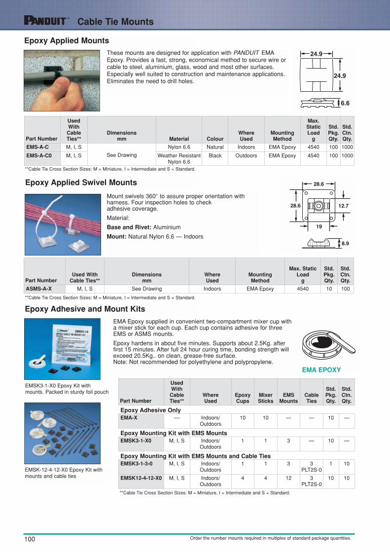
Epoxy Applied MountsThese mounts are designed for application with PANDUIT EMAEpoxy. Provides a fast, strong, economical method to secure wire orcable to steel, aluminium, glass, wood and most other surfaces.Especially well suited to construction and maintenance applications.Eliminates the need to drill holes.
Epoxy Applied Swivel Mounts
Epoxy Adhesive and Mount Kits
Mount swivels 360° to assure proper orientation with harness. Four inspection holes to check adhesive coverage.
Material:
Base and Rivet: Aluminium
Mount: Natural Nylon 6.6 — Indoors
EMA Epoxy supplied in convenient two-compartment mixer cup witha mixer stick for each cup. Each cup contains adhesive for threeEMS or ASMS mounts.
Epoxy hardens in about five minutes. Supports about 2.5Kg. afterfirst 15 minutes. After full 24 hour curing time, bonding strength willexceed 20.5Kg.. on clean, grease-free surface.Note: Not recommended for polyethylene and polypropylene.
EMSK3-1-X0 Epoxy Kit withmounts. Packed in sturdy foil pouch
EMSK-12-4-12-X0 Epoxy Kit withmounts and cable ties
EMA EPOXY
Part Number
UsedWith
CableTies**
Dimensionsmm Material Colour
WhereUsed
MountingMethod
Max.StaticLoad
g
Std.Pkg.Qty.
Std.Ctn.Qty.
EMS-A-C M, I, S
See Drawing
Nylon 6.6 Natural Indoors EMA Epoxy 4540 100 1000
EMS-A-C0 M, I, S Weather ResistantNylon 6.6
Black Outdoors EMA Epoxy 4540 100 1000
Part NumberUsed With
Cable Ties**Dimensions
mmWhereUsed
MountingMethod
Max. StaticLoad
g
Std.Pkg.Qty.
Std.Ctn.Qty.
ASMS-A-X M, I, S See Drawing Indoors EMA Epoxy 4540 10 100
Part Number
UsedWith
CableTies**
WhereUsed
EpoxyCups
MixerSticks
EMSMounts
CableTies
Std.Pkg.Qty.
Std.Ctn.Qty.
Epoxy Adhesive OnlyEMA-X –– Indoors/
Outdoors10 10 — — 10 —
Epoxy Mounting Kit with EMS MountsEMSK3-1-X0 M, I, S Indoors/
Outdoors1 1 3 — 10 —
Epoxy Mounting Kit with EMS Mounts and Cable TiesEMSK3-1-3-0 M, I, S Indoors/
Outdoors1 1 3 3
PLT2S-01 10
EMSK12-4-12-X0 M, I, S Indoors/Outdoors
4 4 12 3PLT2S-0
10 10
**Cable Tie Cross Section Sizes: M = Miniature, I = Intermediate and S = Standard.
**Cable Tie Cross Section Sizes: M = Miniature, I = Intermediate and S = Standard.
**Cable Tie Cross Section Sizes: M = Miniature, I = Intermediate and S = Standard.
Order the number mounts required in multiples of standard package quantities.

101
Cable Tie Mounts
Tie Mounts — Mechanically Applied
Unique cradle design provides maximum stability and rigidity to the wire bundle. Screw or rivet installed.
ExceptTM1S4-M69TM2S8-C100TM3S8-C69TM3S8-C100
TM1 TM2
■TEFZEL is the Registered Trademark of E.I. Dupont de Nemours Co.
Additional Tie Mount Part Numbers Available in specified materials.All are available as standard PANDUIT parts
HeatStabilised
Nylon
FlameRetardant
Nylon
Weather Resistant
Nylon
Weather Resistant
Polypropylene TEFZEL ■
TM1S4-M30 TM1S4-M69 TM1S6-C0 TM2S8-C100 TM2S8-C76TM1S6-M30 TM1S6-M69 TM2R6-M0 TM3S8-C100 TM3S8-C76TM2R6-M30 TM2S6-M69 TM2S6-C0 TM3S10-C76TM2S6-M30 TM2S8-M69 TM2S8-C0TM2S8-M30 TM3S8-C69 TM3R6-M0TM3S8-M30 TM3S10-M69 TM3S10-C0TM3S10-M30 TM1S4-C0TM3S25-M30 TM3S8-C0
Part Number
Used WithCableTies**
Dimensionsmm Material Colour
WhereUsed
HoleDiameter
mm
CounterboreDiameter
mmMountingMethod
Std.Pkg.Qty.
Std.Ctn.Qty.
TM1S4-CM See Drawing
Nylon6.6
Natural Indoors
3.0 5.7 M2.5 Screw 100 500
TM1S6-C 3.7 7.0 M3 Screw 100 500
TM2S6-C
M, I, S See Drawing
3.8 7.0 M3 Screw 100 500
TM2S8-C 4.5 8.4 M4 Screw 100 500
TM2R6-C 4.8 Countersunk M3 Screw/ Rivet 100 500
TM3S8-C
M, I, S, LH See DrawingNylon
6.6Natural Indoors
4.5 8.1 M4 Screw 100 500
TM3S10-C 5.0 9.7 M5 Screw 100 500
TM3S25-C 6.6 12.7 M6 Screw 100 500
TM3R6-C 4.8 Countersunk M3 Screw/ Rivet 100 500
**Cable Tie Cross Section Sizes: M = Miniature, I = Intermediate, S = Standard, and LH = Light-Heavy.
Order the number mounts required in multiples of standard package quantities.
TM3
Hole Diameter — mmPartNumber
HoleDia.
CounterboreDia.
TM1S4 3.0 5.8
TM1S6 3.8 7.1
TM2S6 3.8 7.1
TM2S8 4.6 8.1
TM2R6 4.8 Countersunk
TM3S8 4.6 8.1
TM3S10 5.1 9.9
TM3S25 6.6 12.9
TM3R6 4.8 Countersunk
102
Cable Tie Mounts
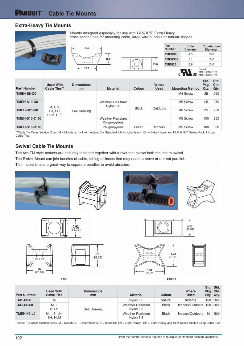
Extra-Heavy Tie MountsMounts designed especially for use with PANDUIT Extra-Heavycross-section ties for mounting cable, large wire bundles or tubular shapes.
Swivel Cable Tie MountsThe two TM style mounts are securely fastened together with a rivet that allows both mounts to swivel.
The Swivel Mount can join bundles of cable, tubing or hoses that may need to move or are not parallel.
This mount is also a great way to separate bundles to avoid abrasion.
ExceptTMEH-S10-C100TMEH-S10-C109
TM3 TMEH
Part NumberUsed With
Cable Ties**Dimensions
mm Material ColourWhereUsed Mounting Method
Std.Pkg.Qty.
Std.Ctn.Qty.
TMEH-S8-Q0
M, I, S, LH, EH,
HLM, HLTSee Drawing
Weather ResistantNylon 6.6
Black Outdoors
M4 Screw 25 250
TMEH-S10-Q0 M5 Screw 25 250
TMEH-S25-Q0 M6 Screw 25 250
TMEH-S10-C100 Weather ResistantPolypropylene
M5 Screw 100 500
TMEH-S10-C109 Polypropylene Green Indoors M5 Screw 100 500
**Cable Tie Cross Section Sizes: M = Miniature, I = Intermediate, S = Standard, LH = Light-Heavy , EH = Extra-Heavy and HLM & HLT Series Hook & LoopCable Ties.
**Cable Tie Cross Section Sizes: M = Miniature, I = Intermediate, S = Standard, LH = Light-Heavy , EH = Extra-Heavy and HLM Series Hook & Loop Cable Ties.
Order the number mounts required in multiples of standard package quantities.
PartNumber
HoleDiameter
CounterboreDiameter
TMEHS8 4.3 13.0
TMEHS10 5.1 13.0
TMEH25 6.6 13.0
Part NumberUsed With Cable Ties
Dimensionsmm Material Colour
WhereUsed
Std.Pkg.Qty.
Std.Ctn.Qty.
TM1-X2-C M
See Drawing
Nylon 6.6 Natural Indoors 100 1000
TM3-X2-C0 M, I, S, LH
Weather ResistantNylon 6.6
Black Indoors/Outdoors 100 1000
TMEH-X2-L0 M, I, S, LH, EH, HLM
Weather ResistantNylon 6.6
Black Indoors/Outdoors 50 500

103
Cable Tie Mounts
Stud Tie MountsEasily applied to bolts or studs with a light hammer blow or turning of the mount. The mounts are designed for use with cable ties to mount wire bundles, air, water andhydraulic lines.
TMSTLHS Type TMSTHS Type
**Cable Tie Cross Section Sizes: M = Miniature, I = Intermediate, S = Standard, LH = Light-Heavy and H = Heavy.
Order the number mounts required in multiples of standard package quantities.
Part NumberUsed With
Cable Ties**Dimensions
mm Material ColourWhereUsed
Bolt/StudSize
MountingMethod
Std.Pkg.Qty.
Std.Ctn.Qty.
TMSTLHS5-C30 M, I, S, LH
See Drawing
Heat Stabilised Nylon 6.6
Black
Indoors M5
Stud Dia.(5 mm)
100 —
TMSTLHS6-C0 M, I, S, LH
Weather ResistantNylon 6.6
Outdoors
M6 100 5000
TMSTLHS8-C0 M, I, S, LH
Weather ResistantNylon 6.6
M8 100 5000
TMSTHS10-C0
M, I, S, LH, H
See Drawing
Weather ResistantNylon 6.6
M10 100 —
TMSTHS13-C0 Weather ResistantNylon 6.6
M13 100 —
TMSTHS16-C0 Weather ResistantNylon 6.6
M16 100 —
TMSTHS19-C0 Weather ResistantNylon 6.6
M19 100 —
104
Cable Tie Mounts
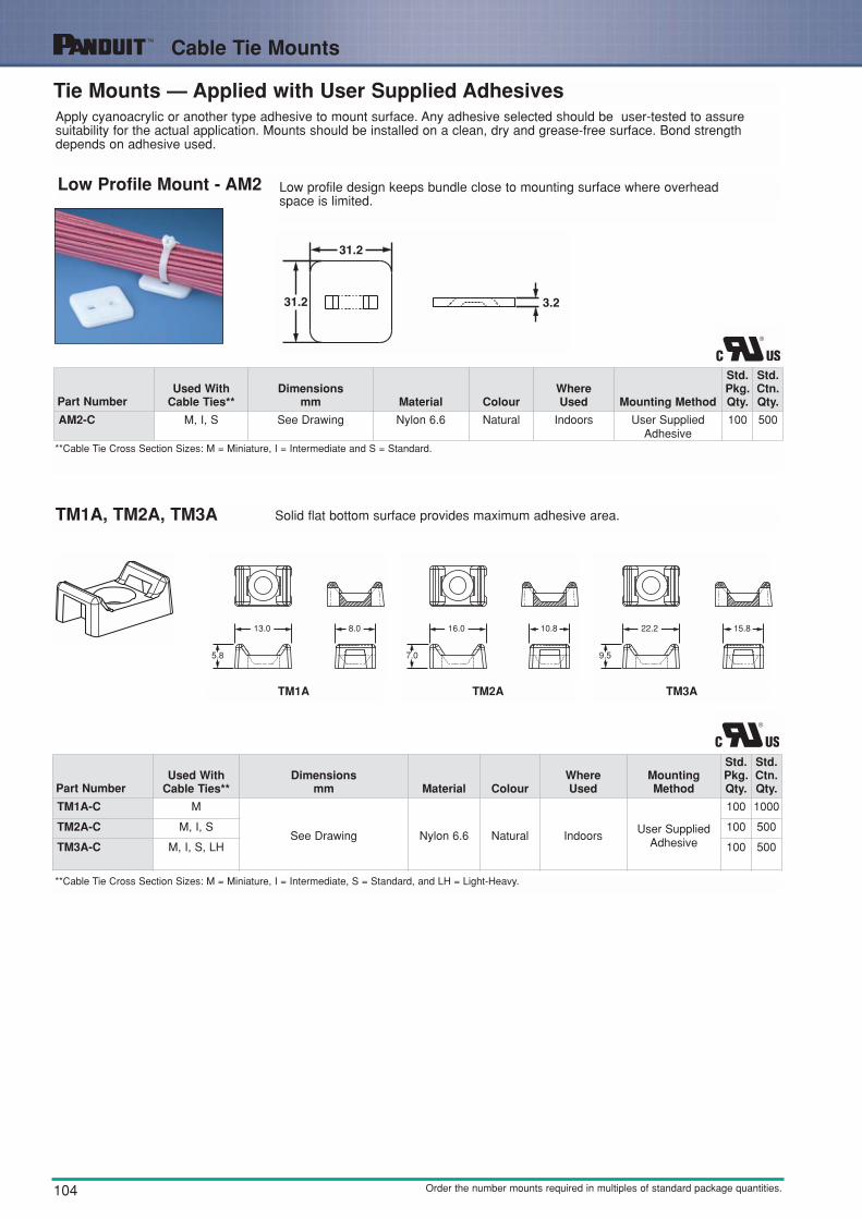
Tie Mounts — Applied with User Supplied AdhesivesApply cyanoacrylic or another type adhesive to mount surface. Any adhesive selected should be user-tested to assure suitability for the actual application. Mounts should be installed on a clean, dry and grease-free surface. Bond strengthdepends on adhesive used.
Low Profile Mount - AM2 Low profile design keeps bundle close to mounting surface where overhead space is limited.
TM1A, TM2A, TM3A Solid flat bottom surface provides maximum adhesive area.
Part NumberUsed With
Cable Ties**Dimensions
mm Material ColourWhereUsed Mounting Method
Std.Pkg.Qty.
Std.Ctn.Qty.
AM2-C M, I, S See Drawing Nylon 6.6 Natural Indoors User SuppliedAdhesive
100 500
Part NumberUsed With
Cable Ties**Dimensions
mm Material ColourWhereUsed
MountingMethod
Std.Pkg.Qty.
Std.Ctn.Qty.
TM1A-C M
See Drawing Nylon 6.6 Natural IndoorsUser Supplied
Adhesive
100 1000
TM2A-C M, I, S 100 500
TM3A-C M, I, S, LH 100 500
**Cable Tie Cross Section Sizes: M = Miniature, I = Intermediate, S = Standard, and LH = Light-Heavy.
**Cable Tie Cross Section Sizes: M = Miniature, I = Intermediate and S = Standard.
Order the number mounts required in multiples of standard package quantities.
TM1A TM2A TM3A
5.8
13.0 8.0
7.0
16.0 10.8
9.5
22.2 15.8

105
Cable Tie Mounts
Screw Applied Tie Anchor Mounts
TA1 Anchor
Low profile and versatile, these screw-installed mounts can be ideal for applications where space is limited. Designed for four-way cable tie insertion, this mount can be mounted in-line or perpendicular to the wire bundle.
TA2 Anchor This mount is installed perpendicular to the wire bundle. Elongated slot permits installingthe screw and adjusting mount position with the bundle attached.
ExceptTA1S8-M69
Part NumberUsed With
Cable Ties**Dimensions
mm Material ColourWhereUsed
MountingMethod
Std.Pkg.Qty.
Std.Ctn.Qty.
TA1S8-C
M, I, S See Drawing
Nylon 6.6 Natural Indoors M4 Screw 100 500
TA1S8-M0 Weather ResistantNylon 6.6
Black Outdoors M4 Screw 1000 5000
TA1S8-M30 Heat Stabilised Nylon6.6
Black Indoors M4 Screw 1000 5000
TA1S8-M69 Flame Retardant Nylon6.6
Ivory Indoors M4 Screw 1000 5000
TA1S10-C Nylon 6.6 Natural Indoors M5 Screw 100 500
TA1S10-M0 Weather ResistantNylon 6.6
Black Outdoors M5 Screw 1000 5000
Part NumberUsed With
Cable Ties**Dimensions
mm Material ColourWhereUsed
MountingMethod
Std.Pkg.Qty.
Std.Ctn.Qty.
TA2-C M, I, S See Drawing Nylon 6.6 Natural Indoors M5 Screw 100 1000
**Cable Tie Cross Section Sizes: M = Miniature, I = Intermediate and S = Standard.
**Cable Tie Cross Section Sizes: M = Miniature, I = Intermediate and S = Standard.
Order the number mounts required in multiples of standard package quantities.

106
Cable Tie Mounts
Screw Applied Low Profile MountsDesigned to secure wire bundles where space is limited.
Knock-In LowProfile Mounts
Secures wires to any pre-drilled panel. Can be installed in any panel thickness. Eliminates screws.
Easy to Install:
1. Push rivet in pre-drilled panel hole.
2. Use PANDUIT Rivet Installation Tool(TNR) or hammer to drive the pin flush tothe base. This drives the rivet into thehole and secures the mount.
3. Attach wires to the mount with cable tie.
1Combination Counter Bore & Counter Sunk Hole 2.2mm Dia. Rivet can also be used) 2Counter Sunk Hole
Part NumberUsed With
Cable Ties**
LengthA
Width B
HeightC
DiameterD
Material ColourWhereUsed
MountingMethod
Std.Pkg.Qty.
Std.Ctn.Qty.mm mm mm mm
LPMM-S2-C M 10.2 8.1 2.5 2.4 1 Nylon 6.6 Natural Indoors M2 Screw 100 1000
LPMM-S5-C M 10.2 8.1 2.5 3.5 2 Nylon 6.6 Natural Indoors M3 Screw 100 1000
LPMS-S8-C M, I, S 19.1 12.7 3.0 4.6 2 Nylon 6.6 Natural Indoors M4 Screw 100 1000
**Cable Tie Cross Section Sizes: M = Miniature, I = Intermediate and S = Standard.
**Cable Tie Cross Section Sizes: M = Miniature, I = Intermediate and S = Standard.
Order the number mounts required in multiples of standard package quantities.
Part NumberUsed With
Cable Ties**Dimensions
mm
HoleDiameter
mm Material Colour Where UsedMountingMethod
Std.Pkg.Qty.
Std.Ctn.Qty.
KIMS-H366-C2
M, I, S See Drawing
3.7
Nylon 6.6
Red
IndoorsIntegral Push
Rivet
100 1000
KIMS-H430-C6 4.3 Blue 100 1000
KIMS-H500-C4 5.0 Yellow 100 1000
107
Cable Tie Plates
Order the number of mounts required in multiples of standard package quantities.
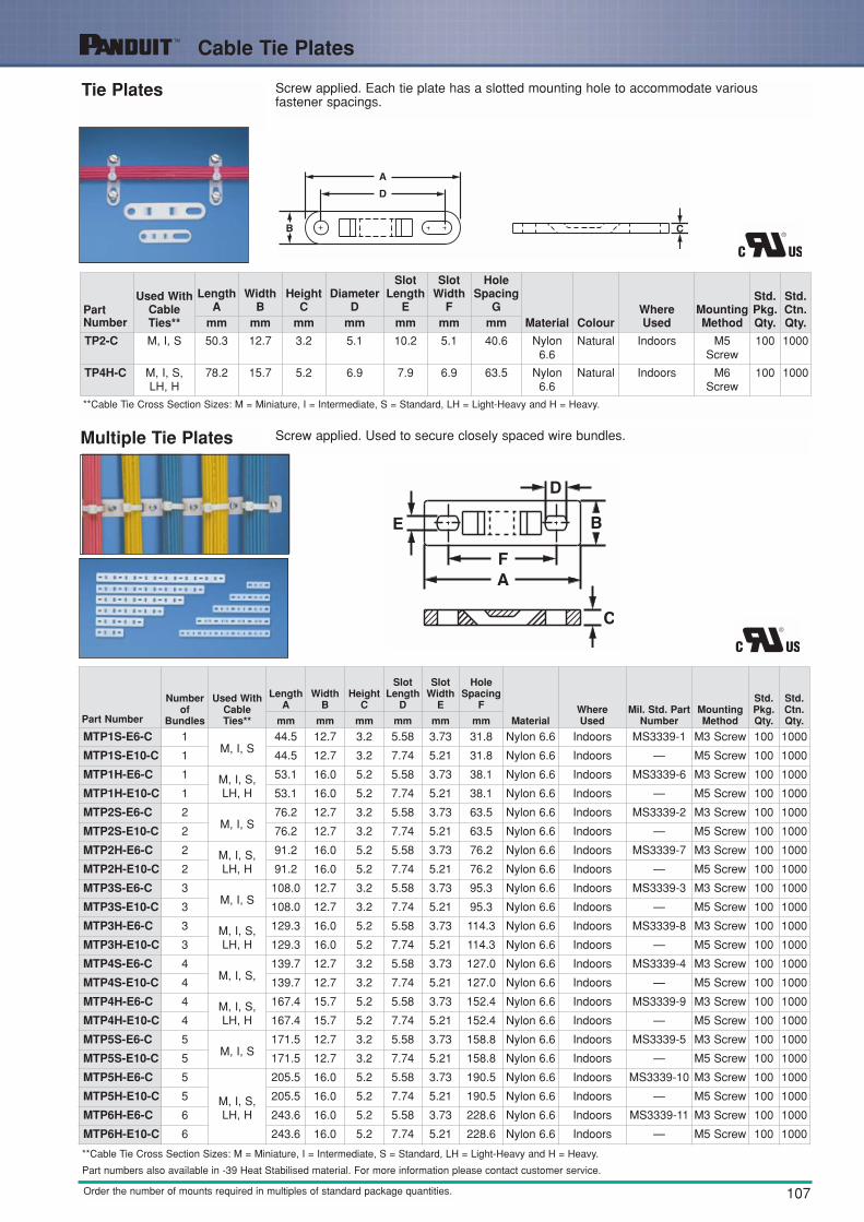
Tie Plates Screw applied. Each tie plate has a slotted mounting hole to accommodate various fastener spacings.
Multiple Tie Plates Screw applied. Used to secure closely spaced wire bundles.
PartNumber
Used WithCableTies**
LengthA
Width B
HeightC
DiameterD
SlotLength
E
SlotWidth
F
HoleSpacing
GMaterial Colour
WhereUsed
MountingMethod
Std.Pkg.Qty.
Std.Ctn.Qty.mm mm mm mm mm mm mm
TP2-C M, I, S 50.3 12.7 3.2 5.1 10.2 5.1 40.6 Nylon6.6
Natural Indoors M5 Screw
100 1000
TP4H-C M, I, S,LH, H
78.2 15.7 5.2 6.9 7.9 6.9 63.5 Nylon6.6
Natural Indoors M6 Screw
100 1000
**Cable Tie Cross Section Sizes: M = Miniature, I = Intermediate, S = Standard, LH = Light-Heavy and H = Heavy.
**Cable Tie Cross Section Sizes: M = Miniature, I = Intermediate, S = Standard, LH = Light-Heavy and H = Heavy.
Part Number
Numberof
Bundles
Used WithCableTies**
LengthA
Width B
HeightC
SlotLength
D
SlotWidth
E
HoleSpacing
F
MaterialWhereUsed
Mil. Std. PartNumber
MountingMethod
Std.Pkg.Qty.
Std.Ctn.Qty.mm mm mm mm mm mm
MTP1S-E6-C 1M, I, S
44.5 12.7 3.2 5.58 3.73 31.8 Nylon 6.6 Indoors MS3339-1 M3 Screw 100 1000
MTP1S-E10-C 1 44.5 12.7 3.2 7.74 5.21 31.8 Nylon 6.6 Indoors — M5 Screw 100 1000
MTP1H-E6-C 1 M, I, S,LH, H
53.1 16.0 5.2 5.58 3.73 38.1 Nylon 6.6 Indoors MS3339-6 M3 Screw 100 1000
MTP1H-E10-C 1 53.1 16.0 5.2 7.74 5.21 38.1 Nylon 6.6 Indoors — M5 Screw 100 1000
MTP2S-E6-C 2M, I, S
76.2 12.7 3.2 5.58 3.73 63.5 Nylon 6.6 Indoors MS3339-2 M3 Screw 100 1000
MTP2S-E10-C 2 76.2 12.7 3.2 7.74 5.21 63.5 Nylon 6.6 Indoors — M5 Screw 100 1000
MTP2H-E6-C 2 M, I, S,LH, H
91.2 16.0 5.2 5.58 3.73 76.2 Nylon 6.6 Indoors MS3339-7 M3 Screw 100 1000
MTP2H-E10-C 2 91.2 16.0 5.2 7.74 5.21 76.2 Nylon 6.6 Indoors — M5 Screw 100 1000
MTP3S-E6-C 3M, I, S
108.0 12.7 3.2 5.58 3.73 95.3 Nylon 6.6 Indoors MS3339-3 M3 Screw 100 1000
MTP3S-E10-C 3 108.0 12.7 3.2 7.74 5.21 95.3 Nylon 6.6 Indoors — M5 Screw 100 1000
MTP3H-E6-C 3 M, I, S,LH, H
129.3 16.0 5.2 5.58 3.73 114.3 Nylon 6.6 Indoors MS3339-8 M3 Screw 100 1000
MTP3H-E10-C 3 129.3 16.0 5.2 7.74 5.21 114.3 Nylon 6.6 Indoors — M5 Screw 100 1000
MTP4S-E6-C 4M, I, S,
139.7 12.7 3.2 5.58 3.73 127.0 Nylon 6.6 Indoors MS3339-4 M3 Screw 100 1000
MTP4S-E10-C 4 139.7 12.7 3.2 7.74 5.21 127.0 Nylon 6.6 Indoors — M5 Screw 100 1000
MTP4H-E6-C 4 M, I, S,LH, H
167.4 15.7 5.2 5.58 3.73 152.4 Nylon 6.6 Indoors MS3339-9 M3 Screw 100 1000
MTP4H-E10-C 4 167.4 15.7 5.2 7.74 5.21 152.4 Nylon 6.6 Indoors — M5 Screw 100 1000
MTP5S-E6-C 5M, I, S
171.5 12.7 3.2 5.58 3.73 158.8 Nylon 6.6 Indoors MS3339-5 M3 Screw 100 1000
MTP5S-E10-C 5 171.5 12.7 3.2 7.74 5.21 158.8 Nylon 6.6 Indoors — M5 Screw 100 1000
MTP5H-E6-C 5
M, I, S,LH, H
205.5 16.0 5.2 5.58 3.73 190.5 Nylon 6.6 Indoors MS3339-10 M3 Screw 100 1000
MTP5H-E10-C 5 205.5 16.0 5.2 7.74 5.21 190.5 Nylon 6.6 Indoors — M5 Screw 100 1000
MTP6H-E6-C 6 243.6 16.0 5.2 5.58 3.73 228.6 Nylon 6.6 Indoors MS3339-11 M3 Screw 100 1000
MTP6H-E10-C 6 243.6 16.0 5.2 7.74 5.21 228.6 Nylon 6.6 Indoors — M5 Screw 100 1000
Part numbers also available in -39 Heat Stabilised material. For more information please contact customer service.

108
Cable Tie Mounts
Order the number of mounts required in multiples of standard package quantities.
Right Angle Mounts Secure wire bundles that run through bulkheads or cabinet holes, holding them away fromsharp edges. Can also be used to mount wire bundles adjacent to any surface. Screw or rivet applied.
Lightening HoleMounts
Used to secure wire bundles which run through bulkhead lightening holes 22.1mm diameter or larger) and keep bundles away from sharp edges. Only one screw or rivet needed.
Part Number
UsedWith
CableTies**
LengthA
Width B
HeightC
DiameterD
HoleSpacing
EMaterial Colour
WhereUsed
Mil. Std.Part
NumberMountingMethod
Std.Pkg.Qty.
Std.Ctn.Qty.mm mm mm mm mm
RAMS-S3-M M, I, S 14.2 9.9 11.0 2.4 7.1
Nylon6.6
Natural Indoors
MS3341-2 M2.5 Screw or2.4 RoundHead Rivet
1000 5000
RAMH-S6-D
M, I, S,LH, H
25.4 19.1
25.4 3.2
12.7
MS3341-1 M3 Screw or3.2 RoundHead Rivet
500 5000
RAMH-S10-D 25.4 5.1 — M5 Screw or4.7 RoundHead Rivet
500 5000
Part Number
Used WithCableTies**
DiameterD Material Colour
WhereUsed
Mil. Std. PartNumber Mounting Method
Std.Pkg.Qty.
Std.Ctn.Qty.
LHMS-S5-C
M, I, S
3.2
Nylon 6.6 Natural Indoors
— M3 Screw or 3.2 Rivet 100 500
LHMS-S6-C 3.7 MS3340-1 M3 Screw or 3.5 Rivet 100 500
LHMS-S10-C 4.9 — M5 Screw or 4.7 Rivet 100 500
**Cable Tie Cross Section Sizes: M = Miniature, I = Intermediate, S = Standard, LH = Light-Heavy and H = Heavy.
**Cable Tie Cross Section Sizes: M = Miniature, I = Intermediate, and S = Standard.
109
Cable Tie Mounts
Order the number of mounts required in multiples of standard package quantities.
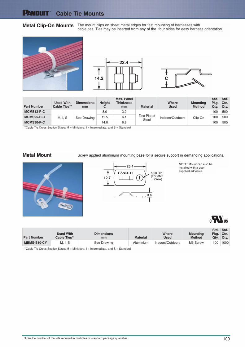
Metal Clip-On Mounts The mount clips on sheet metal edges for fast mounting of harnesses with cable ties. Ties may be inserted from any of the four sides for easy harness orientation.
Metal Mount Screw applied aluminium mounting base for a secure support in demanding applications.
NOTE: Mount can also beinstalled with a usersupplied adhesive.
Part NumberUsed With
Cable Ties**Dimensions
mmHeight
C
Max. PanelThickness
mm MaterialWhereUsed
MountingMethod
Std.Pkg.Qty.
Std.Ctn.Qty.
MCMS12-P-C
M, I, S See Drawing
8.0 3.2Zinc Plated
SteelIndoors/Outdoors Clip-On
100 500
MCMS25-P-C 11.5 6.1 100 500
MCMS30-P-C 14.0 6.9 100 500
**Cable Tie Cross Section Sizes: M = Miniature, I = Intermediate, and S = Standard.
**Cable Tie Cross Section Sizes: M = Miniature, I = Intermediate, and S = Standard.
Part NumberUsed With
Cable Ties**Dimensions
mm MaterialWhereUsed
MountingMethod
Std.Pkg.Qty.
Std.Ctn.Qty.
MBMS-S10-CY M, I, S See Drawing Aluminium Indoors/Outdoors M5 Screw 100 1000

110
Cable Tie Mounts
Order the number of mounts required in multiples of standard package quantities.
Winged Push Mounts Push mounts require no adhesive or additional mounting hardware. They are inserted intopre-drilled holes. The winged base applies pressure on the panel wall to provide a moresecure mount in high vibration applications. Can be used where only one side of the panelis accessible.
PWMS-H25 TM2PWH25
Push Mounts
This part is a version of the mount shownabove, but without tensioning wings.
Push Button Mounts
Designed for use where both sides of thepanel are accessible.
Part Number
Used WithCableTies**
Dimensionsmm
Max. PanelThickness
mm
Panel HoleDiameter
mm Material ColourWhereUsed
MountingMethod
Std.Pkg.Qty.
Std.Ctn.Qty.
PWMS-H25-C
M, I, S See Drawing
2.7
6.4
Nylon 6.6 Natural Indoors
Push Barb
100 1000
PWMS-H25-M0 2.7 Weather ResistantNylon 6.6
Black Outdoors 1000 5000
TM2PWH25-C 2.3 Nylon 6.6 Natural Indoors 100 500
Part Number
Used WithCableTies**
Dimensionsmm
Max.Panel
Thickness
PanelHole
Diameter Material ColourWhereUsed
MountingMethod
Std.Pkg.Qty.
Std.Ctn.Qty.
PM2H25-C
M, I, S See Drawing 3.2 6.4
Nylon 6.6 Natural Indoors
Push Barb
100 500
PM2H25-M0 Weather ResistantNylon 6.6
Black Outdoors 1000 5000
PM2H25-M30 Heat StabilisedNylon 6.6
Black Indoors 1000 5000
Part Number
Used WithCableTies**
Dimensionsmm
Max. PanelThickness
mm
Panel HoleDiameter
mm Material ColourWhereUsed
MountingMethod
Std.Pkg.Qty.
Std.Ctn.Qty.
PBMS-H25-C
M, I, S See Drawing 3.2 6.4
Nylon 6.6Natural Indoors
Push Barb
100 1000
PBMS-H25-C14 Grey Indoors 100 1000
PBMS-H25-M0 Weather ResistantNylon 6.6
Black Outdoors 1000 5000
PBMS-H25-M30 Heat Stabilised Nylon6.6
Black Indoors 1000 5000
**Cable Tie Cross Section Sizes: M = Miniature, I = Intermediate, and S = Standard.
**Cable Tie Cross Section Sizes: M = Miniature, I = Intermediate, and S = Standard.
**Cable Tie Cross Section Sizes: M = Miniature, I = Intermediate, and S = Standard.

111
Cable Tie Mounts
Order the number of mounts required in multiples of standard package quantities.
Masonry Push Mounts Used to secure wire, cable or tubing to masonry surfaces. Installed quickly into pre-drilled holes. Holds bundle securely.
Wood Push Mount Used to secure wire, cable, or tubing to wood surfaces. Driven into wood with hammer, barbed design holds mount in place — rated for 27Kg. pullout.
MPMS19-C0MPMS25-C0MPMH38-L0
MPMWH32-L0
1. Drill hole using correct size bit. 2. Hammer mount into hole. 3. Place cable tie through mount. 4. Install wires or cable.
Part NumberUsed With
Cable Ties**
GripLength Height
DrillDepth
HoleDiameter
Material ColourWhereUsed
MountingMethod
Std.Pkg.Qty.
Std.Ctn.Qty.A B mm mm
MPMS19-C0 M, I, S 24.6 6.4 31.8 5.0
Impact ModifiedWeather
Resistant Nylon6.6
Black Outdoors Tree Barb
100 500
MPMS25-C0 M, I, S 24.6 6.9 31.8 6.4 100 500
MPMH38-L0 M, I, S, LH, H & HLM
31.8 7.5 38.1 10.0 50 500
MPMWH32-L0 M, I, S, LH, H & HLM
35.8 7.1 35.8 8.0 50 500
Part NumberUsed With
Cable Ties**Dimensions
mm MaterialWhereUsed
MountingMethod
Std.Pkg.Qty.
Std.Ctn.Qty.
WPMH-C M, I, S, LH, H & HLM
See Drawing Plated Steel Indoors/Outdoors Hammer intoWood
100 500
**Cable Tie Cross Section Sizes: M = Miniature, I = Intermediate, S = Standard, LH = Light-Heavy, H = Heavy and HLM = Hook and Loop Cable Ties.
**Cable Tie Cross Section Sizes: M = Miniature, I = Intermediate, S = Standard, LH = Light-Heavy, H = Heavy and HLM = Hook and Loop Cable Ties.

112
Cable Tie Mounts
Order the number of mounts required in multiples of standard package quantities.
Control Panel MountInstalled behind control panel switch. Ideal for high strain areas where cable is routed from panel door to panel. Compatible with most control panel switch designs.
PAN-POST ™ Standoff Supports wire bundles above or away from surface
Part NumberUsed With
Cable Ties**
HeightA
DiameterB
Colour Material Screw Size
Std.Pkg.Qty.
Std.Ctn.Qty.mm mm
PP1S-S10-X
M, I, S
50.8 5.1
Natural Nylon 6.6
M5 Screw 10 100
PP1S-S12-X 50.8 5.8 M5.5 Screw 10 100
PP2S-S10-X 116.8 5.1 M5 Screw 10 100
PP2S-S12-X 116.8 5.8 M5.5 Screw 10 100
**Cable Tie Cross Section Sizes: M = Miniature, I = Intermediate, and S = Standard.
**Cable Tie Cross Section Sizes: M = Miniature, I = Intermediate, and S = Standard.
Part NumberUse With
Cable Ties**
Lengthmm
Widthmm
Heightmm
HoleDiameter
mm
Material Mounting Method
Std.Pkg.Qty.
Std.Ctn.Qty.A B C D
CPM87S-C
M,I,S
51.1 22.6 4.3 22.6
Zinc Plated Steel Control Panel Switch
100 1000
CPM122S-C 71.7 31.0 4.3 31.0 100 1000

113
Cable Tie Mounts
Order the number of mounts required in multiples of standard package quantities.
Right Angle Base For use in perpendicular applications. Supports cable above the mount surface.
Flat Cable Mounting System Secures stacked cables, folds and breakouts as well as laminated and mouldedbus bars.
Base FCB
Plate FCP
Mounting Application
Use one base, one corresponding sizeplate and one intermediate cable tie.
Bundling Application
Use two plates (same size) andone intermediate cable tie.
Part Number
Max. FlatCable Width
mm
LengthA
Colour MaterialWhereUsed
MountingMethod
Std.Pkg.Qty.
Std.Ctn.Qty.mm
RAFCBI1-S6-C20 25.4 44.4
Black Nylon 6.6 Indoors M3 Screw
100 1000
RAFCBI2-S6-C20 50.8 70.6 100 1000
RAFCBI3-S6-C20 76.2 96.8 100 1000
Part Number
Lengthmm
Widthmm
Heightmm
HoleDiameter
mm
HoleSpacing
mmColour Material
WhereUsed
MountingMethod
Std.Pkg.Qty.
Std.Ctn.Qty.A B C D E
FCBI1-A-C20 83.5 9.5 3.8 5.1 —
Black Nylon 6.6 IndoorsUser supplied
adhesive
100 1000
FCBI2-A-C20 88.9 9.5 3.8 5.1 — 100 1000
FCBI3-A-C20 114.8 9.5 3.8 5.1 — 100 1000
FCBI1-S10-C20 83.5 9.5 3.8 5.1 52.8
Black Nylon 6.6 Indoors M5 Screw
100 1000
FCBI2-S10-C20 88.9 9.5 3.8 5.1 78.7 100 1000
FCBI3-S10-C20 114.8 9.5 3.8 5.1 104.6 100 1000
Part Number
MaximumFlat Cable
Width mm
Lengthmm
Width mm
Heightmm
Colour MaterialWhereUsed
MountingMethod
Std.Pkg.Qty.
Std.Ctn.Qty.A B C
FCPI1-C20 25.4 32.8 26.4 5.1
Black Nylon 6,6 Indoors Cable Ties
100 1000
FCPI2-C20 50.8 58.7 51.8 5.1 100 1000
FCPI3-C20 76.2 84.3 77.2 5.1 100 1000

114
Cable Tie Mounts — Connector Rings
Order the number of mounts required in multiples of standard package quantities.
Closed Connector Rings Connect multiple wire bundles or hang bundles from conduit, eliminating the need for saddle clamps.
Open Connector Ring Designed to “add on” wire bundles without changing cable ties.
Part NumberUsed With
Cable Ties**Dimensions
mm Material ColourWhereUsed Mounting Method
Std.Pkg.Qty.
Std.Ctn.Qty.
CROS-M M, I, S See Drawing Nylon 6.6 Natural Indoors Connects to M,I,SCable Ties
1000 5000
**Cable Tie Cross Section Sizes: M = Miniature, I = Intermediate, S = Standard and LH = Light-Heavy.
**Cable Tie Cross Section Sizes: M = Miniature, I = Intermediate, and S = Standard.
Part NumberUsed With
Cable Ties**
Length A Width B Height C
Material ColourWhereUsed
MountingMethod
Std.Pkg.Qty.
Std.Ctn.Qty.mm mm mm
CR2-M M, I, S 8.4 5.1 5.0 Nylon 6.6 Natural Indoors
Cable Ties
1000 10000
CR4H-M M, I, S, LH 14.5 7.6 9.1 1000 10000
CR4H-M0 M, I, S, LH 14.5 7.6 9.1 WeatherResistantNylon 6.6
Black Indoors/Outdoors
1000 10000
115
Cable Tie Mounts
Order the number of mounts required in multiples of standard package quantities.
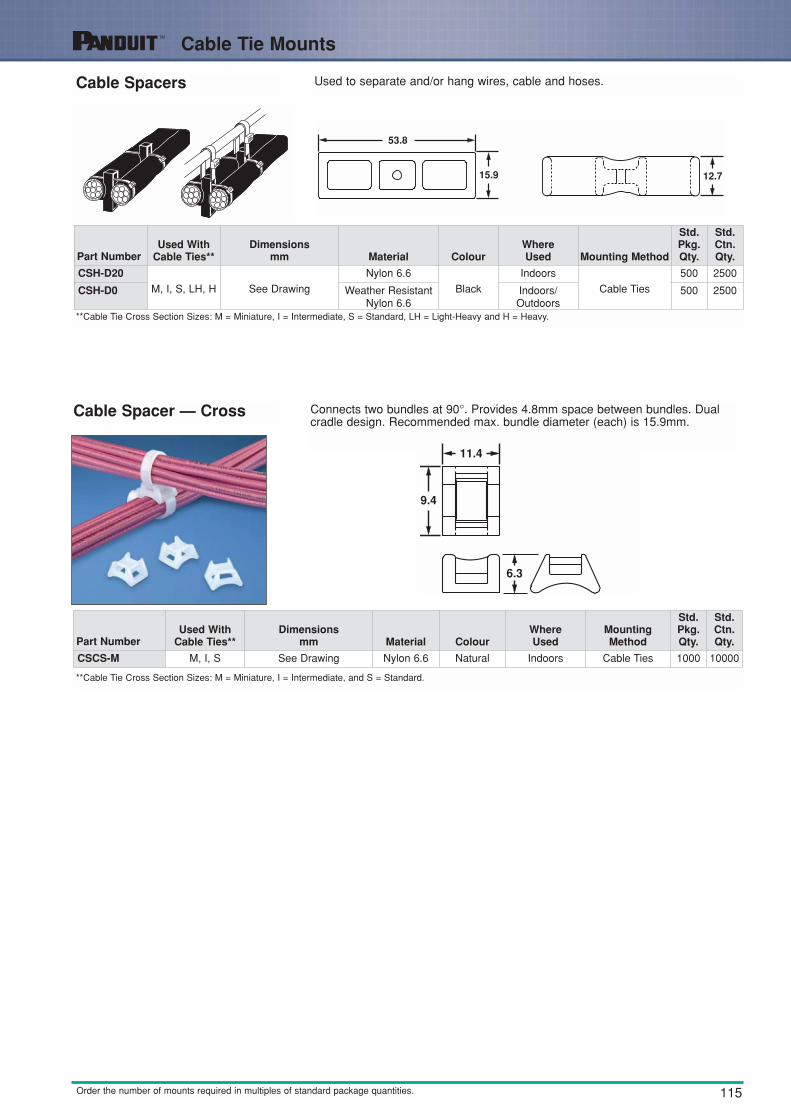
Cable Spacers Used to separate and/or hang wires, cable and hoses.
Cable Spacer — Cross Connects two bundles at 90°. Provides 4.8mm space between bundles. Dualcradle design. Recommended max. bundle diameter (each) is 15.9mm.
**Cable Tie Cross Section Sizes: M = Miniature, I = Intermediate, and S = Standard.
Part NumberUsed With
Cable Ties**Dimensions
mm Material ColourWhereUsed Mounting Method
Std.Pkg.Qty.
Std.Ctn.Qty.
CSH-D20M, I, S, LH, H See Drawing
Nylon 6.6
Black
Indoors
Cable Ties
500 2500
CSH-D0 Weather ResistantNylon 6.6
Indoors/Outdoors
500 2500
**Cable Tie Cross Section Sizes: M = Miniature, I = Intermediate, S = Standard, LH = Light-Heavy and H = Heavy.
Part NumberUsed With
Cable Ties**Dimensions
mm Material ColourWhereUsed
MountingMethod
Std.Pkg.Qty.
Std.Ctn.Qty.
CSCS-M M, I, S See Drawing Nylon 6.6 Natural Indoors Cable Ties 1000 10000

116
Tie Harness Mounts
Order the number of mounts required in multiples of standard package quantities.
Tie Harness Mounts Tie Harness Mounts are designed to be attached to the wire harness during assemblywith 2 cable ties. Ties can be installed by hand or, more efficiently, with PANDUIT PATAutomatic Cable Tie Tooling. Use with Harness Board Standoff Post found on page140. Available with or without corrugated loom tubing location tab.
Tie Harness Mount for Single Cable Tie — Unique mount is attached to harness automatically as tie is installed
• Secured with only 1 cable tie• Can be used with auto-fed or loose piece cable ties• Cable ties can be installed by hand with PANDUIT Automatic
Cable Tie Tooling Installation Systems or pneumatic tool or hand operated cable tie tools
• Winged design prevents vibration• Barb design is easy to insert into pre-drilled hole• 22.5Kg. vertical extraction force from 6.0mm hole
THMSP—Push Barb Style THMSC—Tree Barb Style
Part NumberUsed With
Cable Ties**Dimensions
mm
PanelThickness
mm
Panel HoleDiameter
mm Material ColourWhereUsed
MountingMethod
Std.Pkg.Qty.
Std.Ctn.Qty.
THM1SC-C
M, I, S See Drawing 3.4 6.5
Nylon 6.6 Natural Indoors
Push Barb
100 1000
THM1SC-C30 HeatStabilisedNylon 6.6
Black Indoors/High Temp
100 1000
**Cable Tie Cross Section Sizes: M = Miniature, I = Intermediate, and S = Standard.
Part Number
UsedWith
CableTies
LengthA
Width B
HeightC
Max. PanelThickness
Panel HoleDiameter
RangeMaterial Colour
WhereUsed
MountingMethod
Std.Pkg.Qty.
Std.Ctn.Qty.mm mm mm mm mm
FOR CORRUGATED LOOM TUBING - A location tab on the mount shelf aligns with the corrugated tubing groovesto ensure proper mount location during assemblyTHMSP20-C
M, I, S 39 9.4
16.5 4.1
6.2 - 7.2
Nylon 6.6 Natural Indoors
PushBarb
100 1000
THMSP20-C30 Heat StabilisedNylon 6.6
Black Indoors/High Temp
100 1000
THMSP25-C
18.3 5.8
Nylon 6.6 Natural Indoors 100 1000
THMSP25-C30 Heat StabilisedNylon 6.6
Heat StabilisedNylon 6
Black
Indoors/High Temp
100 1000
THMSC35-C63011.7 6.4 6.2 - 6.8
Black Tree Barb
100 1000
THMSC35-C639 Natural 100 1000
FOR DISCRETE WIRING - No location tab for applications not requiring the use of corrugated loom tubing
THMSP20F-C
M, I, S 39 9.4
16.5 4.1
6.2 - 7.2
Nylon 6.6 Natural Indoors
PushBarb
100 1000
THMSP20F-C30 Heat StabilisedNylon 6.6
Black Indoors/High Temp
100 1000
THMSP25F-C
18.3 5.8
Nylon 6.6 Natural Indoors 100 1000
THMSP25F-C30
Heat StabilisedNylon 6
Black
Indoors/High Temp
100 1000
THMSC35F-C63011.7 6.4 6.2 - 6.8
Black Tree Barb
100 1000
THMSC35F-C639 Natural 100 1000
**Cable Tie Cross Section Sizes: M = Miniature, I = Intermediate, and S = Standard.
Heat StabilisedNylon 6.6
117
Marker Plates and Pens
Order the number of mounts required in multiples of standard package quantities.
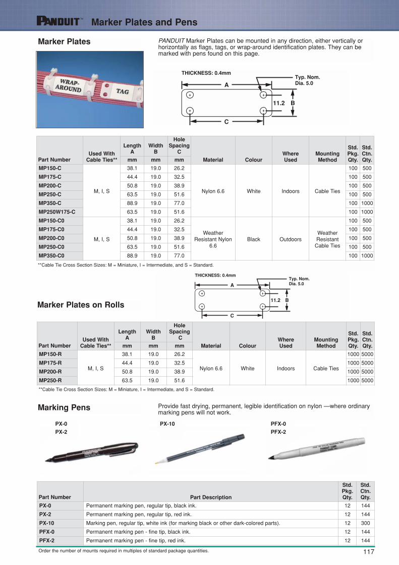
Marker Plates PANDUIT Marker Plates can be mounted in any direction, either vertically orhorizontally as flags, tags, or wrap-around identification plates. They can bemarked with pens found on this page.
Marker Plates on Rolls
Part NumberUsed With
Cable Ties**
LengthA
Width B
HoleSpacing
C
Material ColourWhereUsed
MountingMethod
Std.Pkg.Qty.
Std.Ctn.Qty.mm mm mm
MP150-R
M, I, S
38.1 19.0 26.2
Nylon 6.6 White Indoors Cable Ties
1000 5000
MP175-R 44.4 19.0 32.5 1000 5000
MP200-R 50.8 19.0 38.9 1000 5000
MP250-R 63.5 19.0 51.6 1000 5000
Part NumberUsed With
Cable Ties**
LengthA
Width B
HoleSpacing
C
Material ColourWhereUsed
MountingMethod
Std.Pkg.Qty.
Std.Ctn.Qty.mm mm mm
MP150-C
M, I, S
38.1 19.0 26.2
Nylon 6.6 White Indoors Cable Ties
100 500
MP175-C 44.4 19.0 32.5 100 500
MP200-C 50.8 19.0 38.9 100 500
MP250-C 63.5 19.0 51.6 100 500
MP350-C 88.9 19.0 77.0 100 1000
MP250W175-C 63.5 19.0 51.6 100 1000
MP150-C0
M, I, S
38.1 19.0 26.2
WeatherResistant Nylon
6.6Black Outdoors
WeatherResistant
Cable Ties
100 500
MP175-C0 44.4 19.0 32.5 100 500
MP200-C0 50.8 19.0 38.9 100 500
MP250-C0 63.5 19.0 51.6 100 500
MP350-C0 88.9 19.0 77.0 100 1000
**Cable Tie Cross Section Sizes: M = Miniature, I = Intermediate, and S = Standard.
**Cable Tie Cross Section Sizes: M = Miniature, I = Intermediate, and S = Standard.
Marking Pens Provide fast drying, permanent, legible identification on nylon —where ordinarymarking pens will not work.
PX-0
PX-2
PX-10
Part Number Part Description
Std.Pkg.Qty.
Std.Ctn.Qty.
PX-0 Permanent marking pen, regular tip, black ink. 12 144
PX-2 Permanent marking pen, regular tip, red ink. 12 144
PX-10 Marking pen, regular tip, white ink (for marking black or other dark-colored parts). 12 300
PFX-0 Permanent marking pen - fine tip, black ink. 12 144
PFX-2 Permanent marking pen - fine tip, red ink. 12 144
PFX-0
PFX-2

118
Outside Plant Products
Stackable Cable SpacerJust one part to inventory. Each spacersnaps by hand into another — increasesspacer height by 12.7mm increments.Because there is only one part, on-site sorting is eliminated. Can be used with up to 19mm width lashed cable supports in parallel or perpendicular applications.
Used perpendicular to strandand cable
Used parallel to strand andcable
Underground application
^Stackable Spacers may be installed using Weather-Resistant Lashing Ties. Weather- Resistant Extra-Heavy and Light-Heavy Cable Ties and Stainless SteelTies.
Part NumberUsed withCable Ties
Dimensionsmm Material Colour
WhereUsed
MountingMethod
Std.Pkg.Qty.
Std.Ctn.Qty.
SACS50-T100 ^See Footnote See Drawing Weather ResistantPolypropylene
Black Outdoors Cable Ties 200 2000

119
Cable and Wire Mounting Devices (used without cable ties)
Order the number of mounts required in multiples of standard package quantities.
CLINCHER ™ Adjustable Releasable Clamp
This clamp provides a fast and convenient method of securing bundles from 4.8mm up to 17.5mm diameter. It is available with adhesive backing or screw applied with one M3 screw.
Part Number
BundleDiameter
Rangemm Material Colour
WhereUsed
MountingMethod
Max Static Load
g
Std.Pkg.Qty.
Std.Ctn.Qty.
ARC.68-A-Q
4.8- 17.5 Polypropylene
White
Indoors
Rubber Adhesive
227
25 250
ARC.68-A-Q14 Grey Rubber Adhesive 25 250
ARC.68-S6-Q White M3 Screw
—
25 250
ARC.68-S6-Q14 Grey M3 Screw 25 250
The CLINCHER™ clamp is fast and easy to use...
Lift tab to release

120
Cable and Wire Mounting Devices
Order the number of mounts required in multiples of standard package quantities.
Adhesive Backed Cord ClipsThree sizes of clips to hold cords, tubing, cable, or wire bundles up to 15.7mm diameter. Bundles are easily snapped into or out of the clips.
Push Mount Cord Clip
Mounts snaps easily into pre-drilled holes. Integral mountingdevice eliminates the need for additional mounting hardware. Thewinged design holds mount in place in applications where vibrationis present.
Part Number
Max.Bundle
Diametermm
LengthA
WidthB
HeightC
ClipWidth
DMaterial Colour
WhereUsed
AdhesiveType
MaxStaticLoad
g
Std.Pkg.Qty.
Std.Ctn.Qty.mm mm mm mm
ACC19-A-C
4.8 19.3 16.0 6.5 9.9
Nylon 6.6 Natural Indoors Rubber
91
100 500
ACC19-AT-C Nylon 6.6 Natural Indoors/High Temp Acrylic 100 500
ACC19-A-C20 Nylon 6.6 Black Indoors Rubber 100 500
ACC19-AT-C0 WeatherResistantNylon 6.6
Black Indoors/Outdoors Acrylic 100 500
ACC38-A-C
9.6 25.4 25.4 6.9 12.4
Nylon 6.6 Natural Indoors Rubber
227
100 500
ACC38-AT-C Nylon 6.6 Natural Indoors/High Temp Acrylic 100 500
ACC38-A-C20 Nylon 6.6 Black Indoors Rubber 100 500
ACC38-AT-C0 WeatherResistantNylon 6.6
Black Indoors/Outdoors Acrylic 100 500
ACC62-A-C
15.7 31.5 28.5 16.1 18.8
Nylon 6.6 Natural Indoors Rubber
318
100 500
ACC62-AT-C Nylon 6.6 Natural Indoors/High Temp Acrylic 100 500
ACC62-A-C20 Nylon 6.6 Black Indoors Rubber 100 500
ACC62-AT-C0 WeatherResistantNylon 6.6
Black Indoors/Outdoors Acrylic 100 500
Part Number
Max.Bundle
Diametermm
Dimensionsmm Material Colour
WhereUsed
Panel Dimensions mm MountingMethod
Std.Pkg.Qty.
Std.Ctn.Qty.
Max.Thickness
HoleDiameter
PMCC09H06-M30 9.6
See drawing
Heat StabilisedNylon 6.6
Black Outdoors 2.7 6.4 Push Barb 1000 5000
PMCC38H25-C 9.6 Nylon 6.6 Natural Indoors 2.7 6.4 Push Barb 100 1000
PMCC38H25-M0 9.6 Weather ResistantNylon 6.6
Black Outdoors 2.7 6.4 Push Barb 1000 5000

121
Cable and Wire Mounting Devices
Order the number of mounts required in multiples of standard package quantities.
A1C Type Clips
Holds cords, cables and tubing. Single adhesive pad for confined areas.
"J" ClipsThese low profile "J" clips retain cords, wires, or tubing and are available in five sizes.Their flexible design allows for easy cord insertion yet holds bundles tightly.
Part Number
Max.Bundle
Dia.mm
Lengthmm
Widthmm
Heightmm
Material ColourWhereUsed
MountingMethod
Max. StaticLoad
g
Std.Pkg.Qty.
Std.Ctn.Qty.A B C
A1C12-A-C8 3.0 19.6 16.0 5.8
PVC Grey IndoorsRubber
Adhesive64
100 1000
A1C25-A-C8 6.4 23.1 16.0 9.7 100 1000
A1C38-A-C8 9.5 26.4 16.0 13.0 100 1000
A1C50-A-C8 12.7 29.7 16.0 16.3 100 1000
Part Number
Max.Bundle
Diametermm
Lengthmm
Widthmm
Heightmm
Diametermm
Colour MaterialWhereUsed
MountingMethod
MaxStaticLoad
g
Std.Pkg.Qty.
Std.Ctn.Qty.A B C D
AJC12-A-C 3.0 25.4 21.8 4.8 3.3
Grey PVC IndoorsRubber
Adhesive
181 100 1000
AJC19-A-C 4.8 31.8 22.1 6.6 4.6 227 100 1000AJC25-A-C 6.4 38.1 24.6 7.9 5.8 263 100 1000AJC31-A-C 7.9 44.5 30.1 10.2 7.4 408 100 1000AJC38-A-C 9.6 50.8 32.3 12.7 9.9 454 100 1000

122
Cable and Wire Mounting Devices
Order the number of mounts required in multiples of standard package quantities.
Metal Adhesive Backed Cord Clips
A2C Type ClipsHolds cords, cables and tubing. Two adhesive pads for added strength.
Metal adhesive backed cord clip can be opened and closed without damage to the clip, to remove or add wires quickly and easily.
Part Number
Max.Bundle
Dia.mm
Lengthmm
Widthmm
Heightmm
Material ColourWhereUsed
MountingMethod
Max. StaticLoad
g
Std.Pkg.Qty.
Std.Ctn.Qty.A B C
A2C12-A-C8 3.0 33.0 16.0 5.8
PVC Grey IndoorsRubber
Adhesive169
100 1000A2C25-A-C8 6.4 36.3 16.0 9.1 100 1000A2C38-A-C8 9.5 39.6 16.0 12.4 100 1000A2C50-A-C8 12.7 43.7 16.0 15.5 100 1000
Part Number
Max.Bundle
Dia.mm
Lengthmm
Widthmm
ClipWidthmm
Material ColourWhereUsed
MountingMethod
Max.StaticLoad
g
Std.Pkg.Qty.
Std.Ctn.Qty.A B C
MACC25-A-C 6.4 13.7 20.0 7.1Zinc Plated
Steel— Indoors
RubberAdhesive
95 100 1000
MACC62-A-C 15.7 19.7 30.0 7.1 200 100 1000

123
Cable and Wire Mounting Devices
Order the number of mounts required in multiples of standard package quantities.
Latching Wire ClipsHolds wires, cable and tubing and is available in 6 sizes, with releasable latch. Adhesive backed and push mount stylesavailable. Large mounting base for high bonding strength.
Adhesive Version Push Mount Version
Part Number
Max.Bundle
Dia.mm
Lengthmm
Widthmm
Heightmm
Material ColourWhereUsed
Panel Thickness mm
MountingMethod
Max.StaticLoad
g
Std.Pkg.Qty.
Std.Ctn.Qty.A B C
Max.Thickness
HoleDiameter
LWC19-A-C
4.8 15.5 21.6 9.9
Nylon6.6
Natural
Indoors
— —Rubber
Adhesive
113
100 1000
LWC19-A-C14 Grey 100 1000
LWC19-A-C20 Black 100 1000
LWC25-A-C
6.4 25.4 22.2 11.4
Natural
204
100 1000
LWC25-A-C14 Grey 100 1000
LWC25-A-C20 Black 100 1000
LWC38-A-C
9.5 25.4 25.4 14.2
Natural
227
100 1000
LWC38-A-C14 Grey 100 1000
LWC38-A-C20 Black 100 1000
LWC50-A-L
12.7 25.4 32.0 17.0
Natural
284
50 500
LWC50-A-L14 Grey 50 500
LWC50-A-L20 Black 50 500
LWC75-A-L
19.1 31.5 37.6 22.9
Natural
417
50 500
LWC75-A-L14 Grey 50 500
LWC75-A-L20 Black 50 500
LWC100-A-L
25.4 50.0 56.1 32.0
Natural
1020
50 500
LWC100-A-L14
Nylon6.6
Grey
Indoors
50 500
LWC100-A-L20 Black 50 500
LWC19-H25-C4.8 12.8 21.6 10.4
Natural
2.6 5.6 Push Barb
— 100 1000
LWC19-H25-C14 Grey — 100 1000
LWC25-H25-C
6.4 14.7 21.8 11.9
Natural — 100 1000
LWC25-H25-C14 Grey — 100 1000
LWC25-H25-C20 Black — 100 1000
LWC38-H25-C
9.5 14.7 23.9 14.5
Natural — 100 1000
LWC38-H25-C14 Grey — 100 1000
LWC38-H25-C20 Black — 100 1000
LWC50-H25-L
12.7 19.3 31.8 19.8
Natural — 50 500
LWC50-H25-L14 Grey — 50 500
LWC50-H25-L20 Black — 50 500
LWC75-H25-L
19.1 22.1 36.8 24.7
Natural — 50 500
LWC75-H25-L14 Grey — 50 500
LWC75-H25-L20 Black — 50 500
LWC100-H25-L
25.4 25.4 47.9 33.0
Natural — 50 500
LWC100-H25-L14 Grey — 50 500
LWC100-H25-L20 Black — 50 500

124
Cable and Wire Mounting Device
Order the number of mounts required in multiples of standard package quantities.
Bevel Entry ClipsBevel Entry Clip are available in 3 sizes to hold tubing, cable or wire bundles. The beveled entry makes it easy to snap in thebundle. The clips are available in push barb or adhesive backed styles.
Adhesive Backed Dual Cord Clip
Adhesive Backed Cord Clip
Holds two cables in high temperature applications both indoors and outdoors
Holds a single cable and can be mounted on any flat smooth surface both indoors and outdoors
•NORYL Thermoplastic Resin is a Registered Trademark of General Electric Co.
Part Number
Max.Bundle
Diametermm Material Colour
WhereUsed
MountingMethod
Max.StaticLoad
g
Std.Pkg.Qty.
Std.Ctn.Qty.
ADCC31-AT-C10 2 Bundles5.1 -7.9
NORYL• White Indoors/Outdoors
AcrylicAdhesive
113 100 500
Part Number
Max.Bundle
Diametermm Material Colour
WhereUsed
MountingMethod
Max.StaticLoad
g
Std.Pkg.Qty.
Std.Ctn.Qty.
AMC25-AT-C10 2 bundles6 -7
PVC White Indoors/Outdoors
AcrylicAdhesive
182 100 1000
Adhesive Version Push Mount Version
Part Number
Max.Bundle
Dia.mm
Lengthmm
Widthmm
Heightmm
Material ColourWhereUsed
Max.Panel
Thicknessmm
HoleDia.mm
MountingMethod
Max.StaticLoad
g
Std.Pkg.Qty.
Std.Ctn.Qty.A B C
BEC38-A-L 9.6 37.1 31.5 13.2
Nylon6.6
Natural Indoors — — Rubber Adhesive 411 50 500
BEC38-A-L20 9.6 37.1 31.5 13.2 Black Indoors — — Rubber Adhesive 411 50 500
BEC38-AT-L0 9.6 37.1 31.5 13.2 Black Outdoors — — Acrylic Adhesive 411 50 500
BEC62-A-L 15.7 37.1 31.5 20.1 Natural Indoors — — Rubber Adhesive 411 50 500
BEC62-A-L20 15.7 37.1 31.5 20.1 Black Indoors — — Rubber Adhesive 411 50 500
BEC62-AT-L0 15.7 37.1 31.5 20.1 Black Outdoors — — Acrylic Adhesive 411 50 500
BEC75-A-L 19.0 37.1 37.8 22.6 Natural Indoors — — Rubber Adhesive 493 50 500
BEC75-A-L20 19.0 37.1 37.8 22.6 Black Indoors — — Rubber Adhesive 493 50 500
BEC75-AT-L0 19.0 37.1 37.8 22.6 Black outdoors — — Acrylic Adhesive 493 50 500
BECP38H25-L 9.6 37.1 18.5 25.4 Natural Indoors 1.9 6.4
Inserted into pre-drilled hole
— 50 500
BECP38H25-L20 9.6 37.1 18.5 25.4 Black Indoors 1.9 6.4 — 50 500
BECP75H25-L 19.0 37.3 18.5 34.3 Natural Indoors 1.9 6.4 — 50 500
BECP75H25-L20 19.0 37.3 18.5 34.3 Black Indoors 1.9 6.4 — 50 500
125
Cable and Wire Mounting Device
Order the number of mounts required in multiples of standard package quantities.
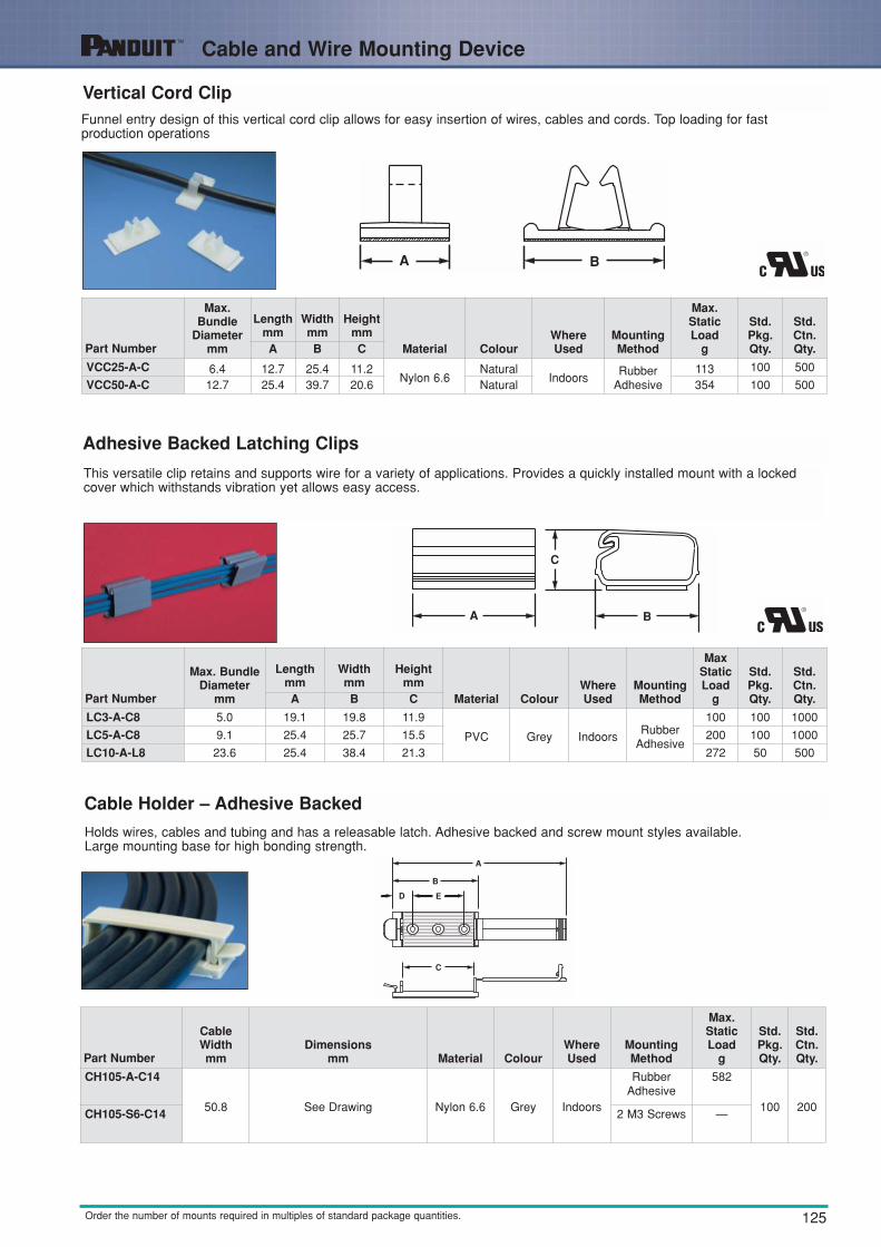
Vertical Cord Clip
Adhesive Backed Latching Clips
This versatile clip retains and supports wire for a variety of applications. Provides a quickly installed mount with a lockedcover which withstands vibration yet allows easy access.
Cable Holder – Adhesive Backed
Holds wires, cables and tubing and has a releasable latch. Adhesive backed and screw mount styles available. Large mounting base for high bonding strength.
Funnel entry design of this vertical cord clip allows for easy insertion of wires, cables and cords. Top loading for fastproduction operations
Part Number
Max. BundleDiameter
mm
Lengthmm
Widthmm
Heightmm
Material ColourWhereUsed
MountingMethod
MaxStaticLoad
g
Std.Pkg.Qty.
Std.Ctn.Qty.A B C
LC3-A-C8 5.0 19.1 19.8 11.9
PVC Grey IndoorsRubber
Adhesive
100 100 1000
LC5-A-C8 9.1 25.4 25.7 15.5 200 100 1000
LC10-A-L8 23.6 25.4 38.4 21.3 272 50 500
Part Number
Max.Bundle
Diametermm
Lengthmm
Widthmm
Heightmm
Material ColourWhereUsed
MountingMethod
Max.StaticLoad
g
Std.Pkg.Qty.
Std.Ctn.Qty.A B C
VCC25-A-C 6.4 12.7 25.4 11.2Nylon 6.6
NaturalIndoors
RubberAdhesive
113 100 500
VCC50-A-C 12.7 25.4 39.7 20.6 Natural 354 100 500
Part Number
CableWidth mm
Dimensionsmm Material Colour
WhereUsed
MountingMethod
Max.StaticLoad
g
Std.Pkg.Qty.
Std.Ctn.Qty.
CH105-A-C14
50.8 See Drawing Nylon 6.6 Grey Indoors
RubberAdhesive
582
100 200CH105-S6-C14 2 M3 Screws —
126
Cable and Wire Mounting Devices
Order the number of mounts required in multiples of standard package quantities.
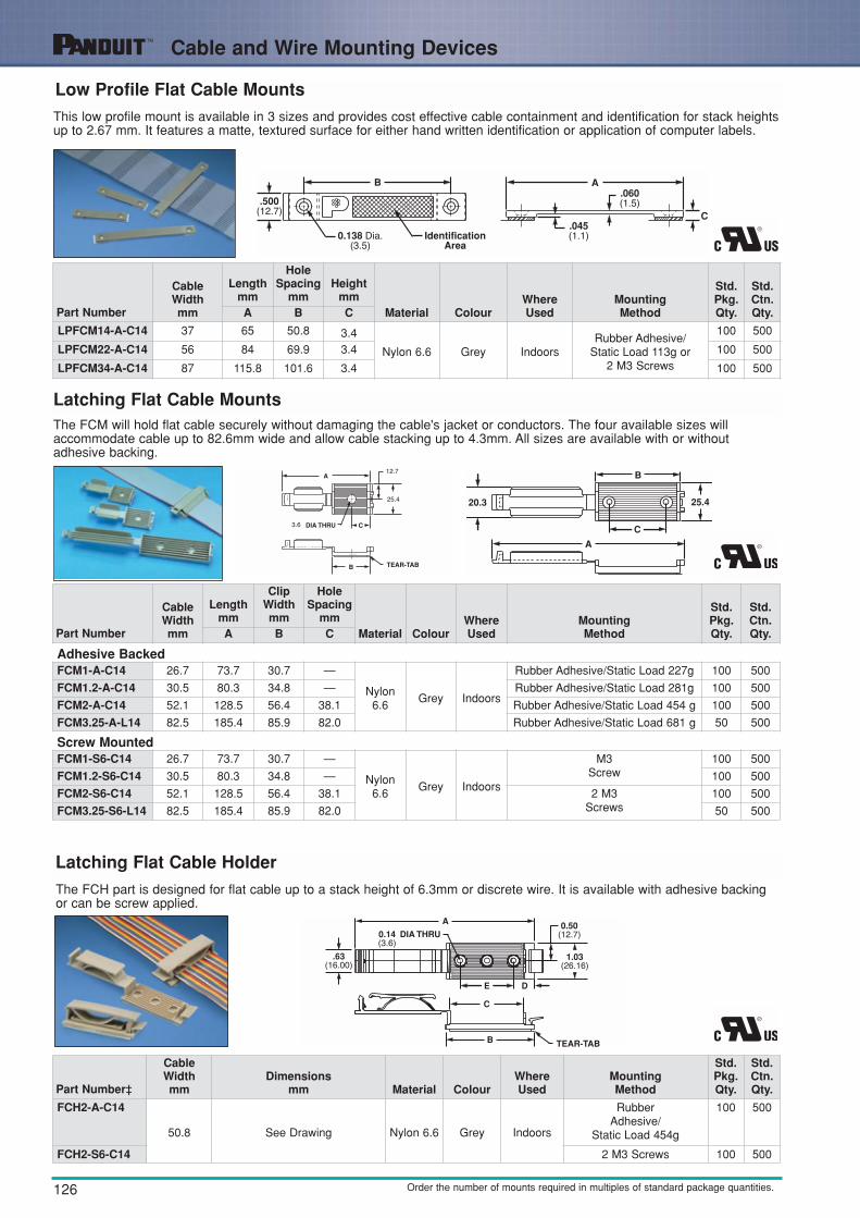
Low Profile Flat Cable Mounts
Latching Flat Cable Holder
Latching Flat Cable Mounts
This low profile mount is available in 3 sizes and provides cost effective cable containment and identification for stack heightsup to 2.67 mm. It features a matte, textured surface for either hand written identification or application of computer labels.
The FCM will hold flat cable securely without damaging the cable's jacket or conductors. The four available sizes will accommodate cable up to 82.6mm wide and allow cable stacking up to 4.3mm. All sizes are available with or without adhesive backing.
The FCH part is designed for flat cable up to a stack height of 6.3mm or discrete wire. It is available with adhesive backingor can be screw applied.
Part Number
CableWidth mm
Lengthmm
HoleSpacing
mmHeight
mmMaterial Colour
WhereUsed
MountingMethod
Std.Pkg.Qty.
Std.Ctn.Qty.A B C
LPFCM14-A-C14 37 65 50.8 3.4
Nylon 6.6 Grey IndoorsRubber Adhesive/
Static Load 113g or 2 M3 Screws
100 500
LPFCM22-A-C14 56 84 69.9 3.4 100 500
LPFCM34-A-C14 87 115.8 101.6 3.4 100 500
Part Number‡
CableWidth mm
Dimensionsmm Material Colour
WhereUsed
MountingMethod
Std.Pkg.Qty.
Std.Ctn.Qty.
FCH2-A-C14
50.8 See Drawing Nylon 6.6 Grey Indoors
RubberAdhesive/
Static Load 454g
100 500
FCH2-S6-C14 2 M3 Screws 100 500
Part Number
CableWidthmm
Lengthmm
ClipWidthmm
HoleSpacing
mmMaterial Colour
WhereUsed
MountingMethod
Std.Pkg.Qty.
Std.Ctn.Qty.A B C
Adhesive BackedFCM1-A-C14 26.7 73.7 30.7 —
Nylon6.6
Grey Indoors
Rubber Adhesive/Static Load 227g 100 500
FCM1.2-A-C14 30.5 80.3 34.8 — Rubber Adhesive/Static Load 281g 100 500
FCM2-A-C14 52.1 128.5 56.4 38.1 Rubber Adhesive/Static Load 454 g 100 500
FCM3.25-A-L14 82.5 185.4 85.9 82.0 Rubber Adhesive/Static Load 681 g 50 500
Screw MountedFCM1-S6-C14 26.7 73.7 30.7 —
Nylon6.6
Grey Indoors
M3Screw
100 500
FCM1.2-S6-C14 30.5 80.3 34.8 — 100 500
FCM2-S6-C14 52.1 128.5 56.4 38.1 2 M3Screws
100 500
FCM3.25-S6-L14 82.5 185.4 85.9 82.0 50 500

127Order the number of mounts required in multiples of standard package quantities.
PAN-CLAMP ™ Heavy Duty Fixed Diameter Clamp• One-piece design significantly reduces installation time • Integrated ribs prevent rotation of cable bundles and
ensures secure grip on hoses
Cable and Wire Mounting Devices
Flat Cable ClipsUsed with any width flat cable for a maximum stack height of 4.3mm.
Part Number
CableWidth mm
Lengthmm
Widthmm
Heightmm
Material ColourWhereUsed
MountingMethod
Std.Pkg.Qty.
Std.Ctn.Qty.A B C
FCC5-A-C8Any
Widthflat
cable
25.4 14.2 7.4
PVC Grey Indoors
RubberAdhesive/Static
Load 113g100 1000
FCC-A-C8 25.4 27.7 9.7 RubberAdhesive/Static
Load 227g100 1000
Part Number
Widthmm
Max.Bundle
Diametermm
BundleOffsetmm
Material Colour
Panel HoleDiameter
mm
PanelThickness
mm
Std.Pkg.Qty.
Std.Ctn.Qty.A B C
PC038-H25D-C0 15.9 9.5 16.3
Impact Modified Weather Resistant
Nylon 6.6Black
7.0 3.2 100 500
PC050-H25D-C0 15.9 12.7 17.9 7.0 3.2 100 500
PC062-H25D-C0 15.9 15.8 19.5 7.0 3.2 100 500
PC075-H25D-C0 15.9 19.1 21.5 7.0 3.2 100 1000
PC087-H25D-C0 15.9 22.1 22.7 7.0 3.2 100 1000
PC100-H25D-C0 15.9 25.4 24.3 7.0 3.2 100 1000
PC112-H25D-C0 15.9 28.5 25.8 7.0 3.2 100 1000
PC125-H25D-C0 15.9 31.8 27.4 7.0 3.2 100 1000
1. Install into 3.2mm thick panel or bracketwith a hole diameter of 7.1mm typical clearance hole for 6mm bolts
2. Moulded barbs keep the clamp secured in thehole during assembly
3. Rivet installs easily by hand. No special tools required

128 Order the number of mounts required in multiples of standard package quantities.
Cable and Wire Mounting Devices
Fixed Diameter Cable ClampsDurable nylon cable clamps are available in two widths: 9.5mm wide for standard use and 12.7 wide for heavy duty use.
Part Number
Type Of
Application
Max.Bundle
Diametermm
Widthmm
BundleOffsetmm
Diametermm
Material ColourWhereUsed
MountingMethod
Std.Pkg.Qty.
Std.Ctn.Qty.A B C D
CCS12-S8-C
Standard
3.1 9.4 8.4 4.2
Nylon 6.6 Natural Indoors
M4 Screw
100 500
CCS19-S8-C 4.8 9.4 10.9 4.2 100 500
CCS25-S8-C 6.3 9.4 10.4 4.2 100 500
CCS25-S10-C 6.3 9.4 10.4 5.1 M5 Screw 100 500
CCS31-S8-C 7.9 9.4 12.4 4.2
M4 Screw
100 500
CCS38-S8-C 9.5 9.4 14.5 4.2 100 500
CCS44-S8-C 11.1 9.4 15.0 4.2 100 500
CCS50-S8-C 12.7 9.4 15.2 4.2 100 500
CCH12-S10-C
Heavy Duty
3.1 12.7 9.1 5.1
M5 Screw
100 500
CCH19-S10-C 4.8 12.7 10.7 5.1 100 500
CCH25-S10-C 6.3 12.7 11.7 5.1 100 500
CCH31-S10-C 7.9 12.7 12.7 5.1 100 500
CCH38-S10-C 9.5 12.7 13.5 5.1 100 500
CCH44-S10-C 11.1 12.7 14.2 5.1 100 500
CCH50-S10-C 12.7 12.7 15.0 5.1 100 500
CCH56-S10-C 14.2 12.7 15.5 5.1 100 500
CCH62-S10-C 15.7 12.7 16.5 5.1 100 500
CCH69-S10-C 17.5 12.7 19.1 5.1 100 500
CCH75-S10-C 19.1 12.7 19.8 5.1 100 500
CCH81-S10-C 20.6 12.7 20.6 5.1 100 500
CCH87-S10-C 22.1 12.7 21.3 5.1 100 500
CCH100-S10-C 25.4 12.7 23.1 5.1 100 500
CCH112-S10-C 28.4 12.7 24.6 5.1 100 500
CCH119-S10-C 30.2 12.7 25.4 5.1 100 500
CCH125-S10-C 31.8 12.7 26.9 5.1 100 500
CCH138-S10-C 34.8 12.7 28.4 5.1 100 500
CCH150-S10-C 38.1 12.7 30.2 5.1 100 500
Note: All parts listed also available in black weatherresistant material (-0). Bulk package only.

129Order the number of mounts required in multiples of standard package quantities.
Wire Retainers
Cable and Wire mounting Devices
Wire slide into the clip and are held in place by tension.
Part Number
BundleDiameter
mmDimensions
mm Material ColourWhereUsed
MountingMethod
Std.Pkg.Qty.
Std.Ctn.Qty.
TWR-C
9.5 See Drawing
Nylon 6.6 Natural Indoors
M3 Screw
100 500
TWR-C0 Weather ResistantNylon 6.6 Black
Indoors/Outdoors 100 500

130 Order the number of mounts required in multiples of standard package quantities.
Cable and Wire Mounting Devices
Snap-In Clips
Wire StandoffsFor retaining wires, cables, components or tubing away from panel or conductive chassis. Finger grip flange can be easilylocked or unlocked for revisions, Hand installed in pre-drilled hole.
The clips hold wire bundles securely. Clips are placed on the bundle then attached to the panel. Designed for pre-drilled holes.
Part Number
Max.Bundle
Dia.mm
StandoffHeight
mmPanel Dimensions
mm
Material ColourWhereUsed
MountingMethod
Std.Pkg.Qty.
Std.Ctn.Qty.A B
PanelThickness
HoleDiameter
WS25-25-C 6.4 6.4 2.0 4.7 - 4.9
Nylon 6.6 Natural Indoors
Insertedinto
Pre-DrilledHole
100 500
WS25-50-C 6.4 12.7 2.0 4.7 - 4.9 100 500
WS25-75-C 6.4 19.1 2.0 4.7 - 4.9 100 500
WS35-25-C 8.9 6.4 2.0 4.7 - 4.9 100 500
WS35-50-C 8.9 12.7 2.0 4.7 - 4.9 100 500
WS35-75-C 8.9 19.1 2.0 4.7 - 4.9 100 500
WS50-25-C 11.9 6.4 2.0 4.7 - 4.9 100 500
WS50-50-C 11.9 12.7 2.0 4.7 - 4.9 100 500
WS50-75-C 11.9 19.1 2.0 4.7 - 4.9 100 500
WS75-25-C 19.8 6.4 2.0 4.7 - 4.9 100 500
WS75-50-C 19.8 12.7 2.0 4.7 - 4.9 100 500
WS75-75-C 19.8 19.1 2.0 4.7 - 4.9 100 500
Part Number
Max.Bundle
Diametermm
Heightmm
Material ColourWhereUsed
Panel Dimensions mm
MountingMethod
Std.Pkg.Qty.
Std.Ctn.Qty.A
MaximumThickness
HoleDiameter
SICH25-C 6.4 20.9
Nylon 6.6 Natural Indoors 2.5 6.4Inserted into
Pre-Drilled Hole
100 500
SICH38-C 9.7 24.9 100 500
SICH50-C 12.7 28.2 100 500
SICH75-C 19.1 35.6 100 500
SICH100-C 25.4 41.9 100 500
SICH150-C 38.0 54.6 100 500
131Order the number of mounts required in multiples of standard package quantities.
Cable and Wire Mounting Devices
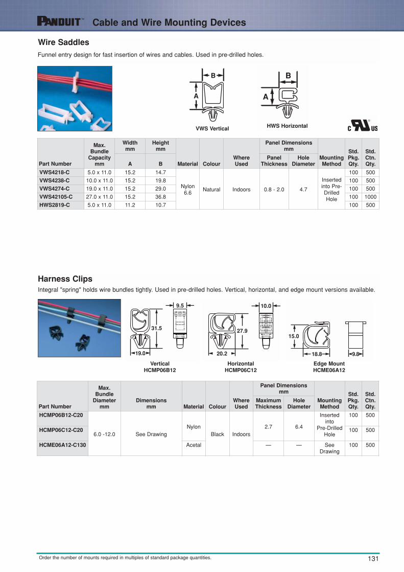
Harness Clips
Wire SaddlesFunnel entry design for fast insertion of wires and cables. Used in pre-drilled holes.
Integral "spring" holds wire bundles tightly. Used in pre-drilled holes. Vertical, horizontal, and edge mount versions available.
Part Number
Max.Bundle
Capacitymm
Width mm
Heightmm
Material ColourWhereUsed
Panel Dimensionsmm
MountingMethod
Std.Pkg.Qty.
Std.Ctn.Qty.A B
PanelThickness
HoleDiameter
VWS4218-C 5.0 x 11.0 15.2 14.7
Nylon6.6
Natural Indoors 0.8 - 2.0 4.7
Insertedinto Pre-DrilledHole
100 500
VWS4238-C 10.0 x 11.0 15.2 19.8 100 500
VWS4274-C 19.0 x 11.0 15.2 29.0 100 500
VWS42105-C 27.0 x 11.0 15.2 36.8 100 1000
HWS2819-C 5.0 x 11.0 11.2 10.7 100 500
Part Number
Max.Bundle
Diametermm
Dimensionsmm Material Colour
WhereUsed
Panel Dimensions mm
MountingMethod
Std.Pkg.Qty.
Std.Ctn.Qty.
MaximumThickness
HoleDiameter
HCMP06B12-C20
6.0 -12.0 See DrawingNylon
Black Indoors2.7 6.4
Insertedinto
Pre-DrilledHole
100 500
HCMP06C12-C20 100 500
HCME06A12-C130 Acetal — — SeeDrawing
100 500
VWS Vertical HWS Horizontal
VerticalHCMP06B12
HorizontalHCMP06C12
Edge MountHCME06A12

132 Order the number of mounts required in multiples of standard package quantities.
Circuit Board Post/Supports
Circuit Board Locking Supports
For board-to-chassis support. Snap-in design for fast assembly. Wing design on chassis mounting provides constant tensionand stability.
Part Number
StandoffHeight
mm
Heightmm
Material ColourWhereUsed
MountingMethod
Std.Pkg.Qty.
Std.Ctn.Qty.A
CBLS18-C 4.7 23.4
Nylon 6.6 Natural Indoors
For Circuit Boards: 1.5mm thick with 4.0mm diameter mounting holes
100 500
CBLS25-C 6.4 24.9 100 1000
CBLS37-C 9.5 28.2
For Chassis: .0.7mm to 2.0mm thick
with 4.7mm to 4.9mm diametermounting holes
100 1000
CBLS50-C 12.7 31.2 100 1000
CBLS62-C 15.9 34.3 100 1000
CBLS75-C 19.1 37.5 100 1000
Circuit Board PostsFor board-to-board or board-to-chassis mounting. Posts snap into pre-drilled holes. Bell flange on bottom end providesgreater stability.
Part Number
StandoffHeight
mm
Heightmm
Material ColourWhereUsed
MountingMethod
Std.Pkg.Qty.
Std.Ctn.Qty.A
CBP12-C 3.0 10.2
Nylon 6.6 Natural IndoorsFor Circuit Boards or Chassis:
1.5mm thick with 4.0mmdiameter mounting holes
100 500
CBP25-C 6.4 13.5 100 500
CBP31-C 7.9 15.0 100 500
CBP37-C 9.4 15.7 100 500
CBP50-C 12.7 19.8 100 500
CBP62-C 15.7 23.0 100 500
CBP75-C 19.1 26.2 100 500
CBP87-C 22.1 29.2 100 500
CBP100-C 25.4 32.5 100 500

133
Selection and Use of Adhesive Mounts
Order the number of pieces in multiples of standard package quantities.
General IntroductionPANDUIT adhesive mounts provide a quick, economical and dependable method of supporting, routing and protecting wires or cables. Some are used with PANDUIT cable ties and others can be used without cable ties.Adhesive backed mounts adhere to a variety of surfaces. This alternative to mechanical fasteners offers theadvantage of lower installed cost with safe, easy to use, quality products.
General Mount GuidelinesPANDUIT pressure sensitive adhesive (foam tape) mounts are intended to secure wire bundles or other lightobjects to smooth surfaces. These mounts are not designed to support excessive loads and should not be usedwhen the maximum expected load exceeds the rated capacity of the mount.
Choosing the Right AdhesivePANDUIT offers two standard pressure sensitive foam tapes which are available on most adhesive backed wiringaccessories products. The general purpose tape is produced with a rubber based adhesive and is identified by an “-A” in the part number. This tape develops its strength extremely fast and can be used in environments with temperatures ranging from -29°C to + 49°C. It is recommended that rubber based adhesivemounts dwell 2 hours after installation, prior to loading. Rubber based adhesive tape is the best choice for mostadhesive mount applications, including powder coated surfaces.
Acrylic based adhesive tape is also available and is identified by an “-AT” in the part number. This tape is for usein environments where continuous exposure to temperatures as high as 82°C is possible. Acrylic based adhesive develops its maximum strength over a longer period of time than rubber based adhesive. It is recommended that acrylic adhesive mounts dwell 8 hours after installation, prior to loading. Acrylic based adhesive tape is a good choice for environments with prolonged exposure to UV rays or temperatures above 49°C.
PANDUIT also offers a two-part epoxy for use in applications where excessive loading is required, or where thesurface to which the mount must be applied is porous rather than smooth. This adhesive is formulated specifically for use on PANDUIT mounts, and is packaged in pre-measured cups to insure the proper ratio ofresin and hardener are mixed, eliminating wasted epoxy.
Applications• To route wires in control panels and switchboards• To support bundles of wires away from moving mechanical devices• Routing and harnessing cables, both indoors and out, to prevent safety hazards• To organise flat cables in many locations with low profile construction• Ideal for supporting wire bundles where holes cannot be made in the substrate• To separate groups of wires for identification
Markets• Original Equipment Manufacturers (OEM)• Construction Industry• Telecommunication Systems• CATV• Aerospace Industry
• Utilities• Electronic Components• Transportation Industry• Appliance Manufacturers• Maintenance and Repair
Operations (MRO)

134
Selection and Use of Adhesive Mounts
Order the number of pieces in multiples of standard package quantities.
Application ChartSince PANDUIT manufacturesadhesive backed mounts with a varietyof adhesive types, this chart should beused as a guideline for choosing thebest adhesive for often-encounteredconditions. Each type of adhesive israted good, fair or poor for some specific mounting surfaces and/orchemical environments.
Surface PreparationFor best results, PANDUIT adhesive mounts should be applied to clean, dry, grease-free surfaces. We recommend that the surface be cleaned prior to mount installation. For rubber and acrylic based foam tape adhesives, a blend of isopropyl alcohol and water 50/50 may be used to clean most surfaces.
For epoxy type adhesives, especially masonry surfaces, be sure to clean all loose particles away before mountinstallation. Some surface abrasion is recommended to achieve maximum strength. A light rubbing with mediumgrit emery cloth or sandpaper is best. Wash after abrading.
Proper Installation Techniques For Pressure Sensitive Adhesive MountsFor proper installation of adhesive mounts with foam tape, simply remove the release liner and place the mountin the desired location. Avoid touching the adhesive prior to positioning the mount. Apply firm pressure to themount for 5 seconds to insure proper adhesion.
Epoxy Adhesive MountsPANDUIT EMA adhesive is a two-part epoxy cement which is packaged in convenient mixer cups containing anequal amount of resin and hardener. Peel the protective covering off and pop the center of the cup in to form amixing bowl. Each cup is supplied with a mixer stick and contains enough epoxy to properly apply three EMSmounts. The resin and hardener should be thoroughly mixed together until the epoxy is a consistent and uniformcolour. The mixer stick can then be used to apply the adhesive to the mount. The epoxy should be forced intothe grooves on the bottom of the mount to obtain optimum bond performance. The mount should be applied tothe surface with light pressure and a back-and-forth twisting motion. Hardening of the epoxy begins five minutesafter mixing at room temperature.
Mount SpacingTo determine the number of mounts touse in a given application, the followingformula can be used as a guideline:
SurfacesRubber Based
Foam Tape MountsAcrylic Based Foam
Tape MountsEpoxy Applied
Adhesive Mounts
PlasticsWoodGlassPainted SurfacesPowder CoatingMetalPaperConcrete, Stone, Masonry
GoodGoodFair
GoodGoodGood1
GoodNot Recommended
GoodGoodGoodGoodFair
Good1
GoodNot Recommended
GoodGoodGoodFair
GoodGoodFair
Good
WaterOilGasolineDilute AcidsDilute AlkalisOrganic SolventsOutdoor Exposure
GoodPoorPoorPoorGoodPoor
Not Recommended
GoodFair3
Fair3
Fair3
Fair3
Fair3
Good
PoorGoodFairFairFair
Not RecommendedGood2
1. Not recommended for use on copper or brass.2. Mounts manufactured from outdoor material only. For specific applications, individual testingprior to extensive use is suggested.3. Depends on concentration, exposure time and chemical composition.
Chemical Resistance
Cable or weight (Kg./m)
Static Load rating of Mount (Kg./m)
Mounts
mSpacing=
Clean surface with a cleancloth and isopropyl alcohol.Allow surface to air dry.
Remove the release liner,being careful not to touch theadhesive.
Apply full thumb pressure forat least 5 seconds.
Allow mount toproperly dwell.

135
Selection and Use of Adhesive Mounts
Order the number of pieces in multiples of standard package quantities.
Proper Storage ConditionsAll PANDUIT adhesive products have an expiration date printed on the package label. Use the followingstorage guidelines:
1. For rubber and acrylic based foam tape adhesives, store in temperatures of 21°C and 45% Relative Humidity (R.H.).
2. For epoxy type adhesives, store in temperatures of 4°C to 25°C and relative humidity not in excess of 45%.Storage in opened containers is not recommended. Using the guidelines above, the shelf life of foam tape is 3years. Shelf life of epoxy is 1 year. Deviation from the recommended storage conditions may reduce the shelflife or adhesive strength. In any case, adhesive products should never be stored near heating vents or otherheat sources, and storage in lower temperatures than those recommended may increase the shelf life.
Stock RotationAdhesive mount inventory should be rotated in order toinsure the quality of the adhesive foam tape. Each packageof PANDUIT adhesive backed mounts has a Quality ControlNumber and a best-if-used-by date on the package label.The best-if-used-by date provides the customer with anaccurate way to control the rotation of inventory, and, as isthe case with all PANDUIT products, the Quality ControlNumber provides complete traceability for all componentsthat go into a specific production run of product.
Mount RemovalThere is no simple or easy method for removing PANDUIT adhesives. A thin wire or razor blade can be moved in between the surfaces when removing foam tape mounts; however, the adhesive residue will remain on thesurface. Epoxy adhesives may be removed with a commercial paint stripping solution.
Best-If-Used-By Date Quality Control Number

136
Harness Board Accessories
Order the number of pieces in multiples of standard package quantities.
Harness Board AccessoriesPANDUIT harness board accessories provide fast routing andforming of wires in harness fabrication. They hold the wires offthe harness board at a uniform height for easy application of cable ties. The accessories are designed for usewith various PANDUIT cable tie installation tools. The Low accessories are used with hand-operated tools. The Highaccessories are used with the automatic tools. To maintain theharness at a uniform height of approx. 33.8mm (at the centre of the harness) above the board, use RERElastic Retainers, BR.75-E6 or BR.5-E6, CPH.75-S8, TJF and SHH1-S8 or SHH3-S8 harness board accessories. Thisheight is suitable for use with PAT1M Automatic Cable TieInstallation Tool.
Wire Retainers —RER Type ReplaceableElastic Retainers
As wires are individually inserted, the bundle is formed. When harness is complete, it can be easily snapped out. Three sizes available for 12.7mm, 19.0mm and 31.8mm bundles.
ER Type Elastic Retainers
ER Type retainers form wire bundles as wires are inserted. Completed bundlesthen snap out. Two sizes available for 12.7mm and 31.8mm bundles.
Replacement ElasticFor economy, the elastic band can bereplaced in the RER Elastic Retainers
without removing the RER base.
PartNumber
RER.5E-XRER.75E-XRER1.25E-X
Pkg.Qty.
101010
Part Number
Max. BundleDiameter
mm
Lengthmm
Widthmm
Heightmm
Diametermm
Colour and MaterialMountingMethod
Std.Pkg.Qty.
Std.Ctn.Qty.A B C D
ER.5-E4-X 12.7 49.8 14.2 25.4 3.3Black Nylon
6.6and ABS
2 M2.5Screw
10 100
ER1.25-E4-X 31.8 73.7 24.08 50.8 3.3 2 M2.5Screw
10 100
Part Number
Max.Bundle
Diametermm
Lengthmm
Widthmm
Heightmm
Diametermm
HoleSpacing
mmColour and Material
MountingMethod
Std.Pkg.Qty.
Std.Ctn.Qty.A B C D E
RER.5-S6-X 12.7 30.0 21.3 48.0 3.6 21.0
Black Nylon 6.6 andWhite Acetal
2 M3Screw
10 50
RER.75-S6-X 19.0 30.0 28.4 56.1 3.6 21.0 10 50
RER1.25-S6-X 31.8 30.0 41.7 72.6 3.6 21.0 10 50
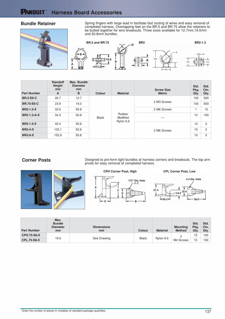
137Order the number of pieces in multiples of standard package quantities.
Bundle Retainer Spring fingers with large lead in facilitate fast routing of wires and easy removal ofcompleted harness. Overlapping feet on the BR.5 and BR.75 allow the retainers tobe butted together for wire breakouts. Three sizes available for 12.7mm,19.0mmand 50.8mm bundles.
Corner Posts Designed to pre-form tight bundles at harness corners and breakouts. The top armpivots for easy removal of completed harness.
BR.5 and BR.75
CPH Corner Post, High CPL Corner Post, Low
BR2 BR2-1.3
Part Number
Max.Bundle
Diametermm
Dimensionsmm Colour Material
MountingMethod
Std.Pkg.Qty.
Std.Ctn.Qty.
CPH.75-S8-X19.0 See Drawing Black Nylon 6.6
2M4 Screws
10 100
CPL.75-S8-X 10 100
Part Number
StandoffHeight
mm
Max. BundleDiameter
mmColour Material
Screw Size Metric
Std.Pkg.Qty.
Std.Ctn.Qty.A B
BR.5-E6-C 26.7 12.7
BlackRubberModifiedNylon 6.6
2 M3 Screws100 500
BR.75-E6-C 23.9 19.0 100 500
BR2-1.3-X 33.5 50.8 2 M6 Screws 1 10
BR2-1.3-A-X 34.3 50.8—
10 100
BR2-1.5-X 40.4 50.8
2 M6 Screws
10 0
BR2-4-X 103.1 50.8 10 0
BR2-6-X 152.9 50.8 10 0
Harness Board Accessories

138
Harness Board Accessories
Order the number of pieces in multiples of standard package quantities.
T-Junction Fixture Using an integrated harness board nail, the T-Junction Fixture moves to form harnesses. When the harness is complete, the fixture can be pushed down foreasy harness removal.
Wire End Holder Secures wire ends with or without terminations whileharness is being fabricated. Wires can be easilyadded or removed from the top, but will hold thewire from axial movement. Used with 0.3mm thru1.5mm wires.
Harness Board Nails Speeds routing of wires. All of the nails have a uniform driving depth insured by a collar stop.Smooth finish on the nails, will not abradewire jackets.
In the “up” position toform harness.
In the “down” position totie and remove harness.
Part Number
Max. BundleDiameter
mmDimensions
mm Colour MaterialMountingMethod
Std.Pkg.Qty.
Std.Ctn.Qty.
TJF-X 34.0 See Drawing Black Nickel Plated Steeland Nylon 6.6
Nail 10 100
Part NumberDimensions
mm Colour MaterialMountingMethod
Std.Pkg.Qty.
Std.Ctn.Qty.
WEH-E8-C See Drawing Black Acetal M4 Screw 100 1000
Part Number
Lengthmm
OverallLength
mmThickness
mmMaterial
MountingMethod
Std.Pkg.Qty.
Std.Ctn.Qty.A B C
HBN.75-T 19.1 34.8 1.9
NickelPlated Steel
Hammered intoHarness Board
200 1000
HBN1-T 25.4 41.1 1.9 200 1000
HBN1.5-T 38.1 53.8 2.1 200 1000
HBN2-T 50.8 66.5 2.4 200 1000
HBN2.5-T 63.5 79.2 2.8 200 1000
HBN3-T 76.2 91.9 3.0 200 1000
HBN4-T 101.6 117.3 3.7 200 1000

139Order the number of pieces in multiples of standard package quantities.
Fanning Strip System
Fanning Strip System
Assures that wires are held in a particular orientation in sophisticated wiring harnesses. Consists of fanning strip and fanning strip holder.
Low Holder (FSH40-X) High Holder (FSHH)
Fanning Strip (FS156)Contains evenly spaced “snap slots”to hold wires in place. No sharpedges to damage wire insulation.Becomes part of the wiring harness.Will accept wires up to 1.0mm. Usedwith FSH40 or FSHH holders.
Used in conjunction with RER.75-S6,BR.75-E6, BR.5-E6 and CPH.75-S8.Ideal for use with PAT cable tie tool.
Part NumberDimensions
mm Colour Material Mounting Method
Std.Pkg.Qty.
Std.Ctn.Qty.
FS156-C See Drawing Natural Nylon 6.6 Fanning Strip Holder 100 1000
FSH40-X Black ABS M4 Screw 10 100
FSHH-X Black ABS M4 Screw 10 100
Harness Board Accessories

140
Harness Board Accessories
Order the number of pieces in multiples of standard package quantities.
Spring Wire BreakoutSystem
Separates and holds wires in a harness while the rest of the harness is being formed.The wires simply pull out from the spring when the harness is complete.
Harness Board Standoff Posts
Used to hold a push mount accessories or a push mount cable tie at a specific location on a harness board. The Standoff Post is placed over a hole in the harnessboard, a bolt is then threaded into the bottom of the standoff from the backside of theboard and tightened. Push mount accessories are inserted into the top of the StandoffPost prior to assembly. When the assembly is complete, the harness and the attachedpush mount are removed from the Standoff Post.
SHH Spring Holder
PBSC SpringWire Breakout
Each SHH Spring Holder is supplied with 1 rigid wire piece to hold the spring laterallyand two M4 50.8mm hex head wood screws. Two sizes available for use with PBSC1and PBSC6.
Part NumberHole Spacing
Material Colour Mounting Method
Std.Pkg.Qty.
Std.Ctn.Qty.A
PBSC1-X 25.4
Steel —
SHH1 Spring Holder 10 100
PBSC3-X 76.2 2 M4 Screws 10 100
PBSC6-X 152.4 SHH3 Spring Holder 10 100
PBSC12-X 304.8 2 M4 Screws used with PBSC1 10 100
SHH1-S8-X 45.7
Nylon 6.6 Black
(2) M4 Screws 10 100
SHH3-S8-X 172.7 2 M4 Screws used with PBSC3 or OBSC6 10 100
Part NumberHeight
AHole Diameter
B For Use With Material Mounting Method
Std.Pkg.Qty.
Std.Ctn.Qty.
HB2SP19-X 50.8 5.1 PLWP, PRWP, WS, VWS, HWS
Aluminium M6 Screw
10 100
HB2SP25-X 101.6 7.5 PLWP, PRWP, PLP, THMS, HCMP, PMCC
10 100

141
Communication Cable Management
Order the number of pieces in multiples of standard package quantities.
Optical FibreNetwork Saddles
The product is designed with rounded edges for routing fibre optic cables. This feature provides a very smooth surface to eliminate the potential for snagging andputting stress on the fibre optic cable.
Waterfall Accessories PANDUIT Waterfall Accessory provides bend radius control in both vertical and horizontal directions when transferring cables from standard ladderrack. Installs easily to the rung or a stringer of the ladder rack with PANDUIT PLTseries cable ties, provided in every package. PANDUIT Waterfall Accessories arepart of a complete cable management system.
VWS Push Mount Type VWSDC Dual Capacity Type
CMW-Kit CMWB- Waterfall Base CMWW-Waterfall Wing
Part Number
Max.Bundle
Diametermm
DImensionsmm Material Colour
WhereUsed
Panel Dimensionsmm
MountingMethod
Std.Pkg.Qty.
Std.Ctn.Qty.
Max.Thickness
HoleDiameter
VWS106-C
26.9 See Drawing Nylon 6.6
Natural
Indoors 2.3 4.7PushMount
100 500
VWS106-C20 Black 100 500
VWSDC-C Natural 100 500
Part Number
BendRadiusLimitmm Material Colour
Width mm
Heightmm Included in Package
Std.Pkg.Qty.
Std.Ctn.Qty.
CMW-KIT—
Glass FilledFlame
RetardantNylon 6.6
Black243.8 124.5
One Base, Two Wings, and Three Cable Ties
1 10
CMW-KIT10 Natural 1 10
CMWB44.45
Black133.1 — One Base and Three Cable Ties
1 10
CMWB10 Natural 1 10
CMWW25.4
Black50.6 124.5 One Bend Radius Control Wing
1 10
CMWW10 Natural 1 10
Wire Bundle StrapWire Bundle Strap provides a quick, durable and inexpensive way to contain wire, cable and tubing. It can be installed onwood, plywood, masonry and other surfaces using standard fasteners.
Part Number
BundleRetaining
Area Material Colour
Dimensionsmm Mounting
Method
Std.Pkg.Qty.A B C D
WBS6-Q — ABS White 25.4 99.6 64.5 6.35 M6 Screw 25
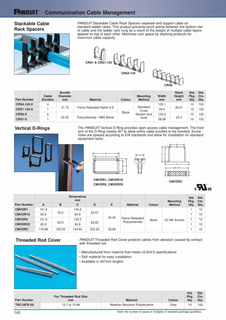
142
Communication Cable Management
Order the number of pieces in multiples of standard package quantities.
PANDUIT Stackable Cable Rack Spacers separate and support cable on standard ladder racks. This product prevents pinch points between the bottom rowof cable and the ladder rack rung as a result of the weight of multiple cable layersapplied on top of each other. Maximise rack space by stacking products for maximum cable capacity.
Stackable CableRack Spacers
The PANDUIT Vertical D-Ring provides open access cable management. The frontarm of the D-Ring rotates 90° to allow entire cable bundles to be inserted. Screwholes are spaced according to EIA standards and allow for installation on standardequipment racks.
Vertical D-Rings
CRS1 & CRS1-125
CMVDR1, CMVDR1S
CMVDR2, CMVDR2SCMVDRC
CRS4-125
CRS6
Part NumberCable
Bundles
BundleDiameter
mm Material ColourMountingMethod
Width mm
StackHeight
mm
Std.Pkg.Qty.
Std.Ctn.Qty.
CRS4-125-X 431.75 Flame Retardant Nylon 6.6
Black
StandardCross
Section andHLM
133.136.07
10 100
CRS1-125-X 1 39.4 10 100
CRS6-X 620.32 Polycarbonate / ABS Blend
133.425.4
10 100
CRS1-X 1 28.58 10 100
Part Number
Dimensionsmm
Material ColourMountingMethod
Std.Pkg.Qty.
Std.Ctn.Qty.A B C D E
CMVDR1 121.930.0
145.252.07
44.45 Flame RetardantPolycarbonate
Black (2) M6 Screws
1 10
CMVDR1S 60.9 82.8 1 10
CMVDR2 121.960.9
145.283.82
1 10
CMVDR2S 60.9 82.8 1 10
CMVDRC 119.88 129.29 143.64 222.25 28.58 1 10
Threaded Rod Cover PANDUIT Threaded Rod Cover protects cables from abrasion caused by contactwith threaded rod.
• Manufactured from material that meets UL94V-0 specifications• Soft material for easy installation• Available in 457mm lengths
Part NumberFor Threaded Rod Size
mm Material Colour
Std.Pkg.Qty.
Std.Ctn.Qty.
TRC18FR-X8 12.7 to 15.88 Weather Resistant Polyethylene Grey 10 100
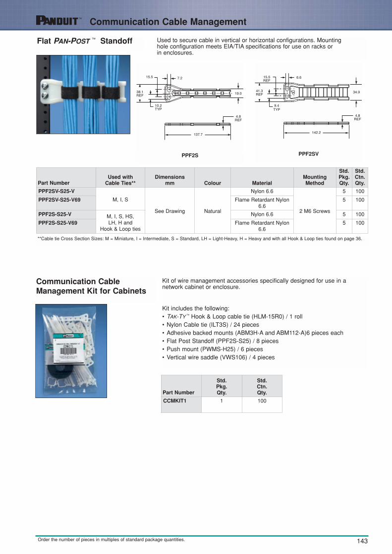
143Order the number of pieces in multiples of standard package quantities.
Flat PAN-POST ™ Standoff Used to secure cable in vertical or horizontal configurations. Mounting hole configuration meets EIA/TIA specifications for use on racks or in enclosures.
Communication CableManagement Kit for Cabinets
Kit of wire management accessories specifically designed for use in a network cabinet or enclosure.
Kit includes the following:• TAK-TY ™ Hook & Loop cable tie (HLM-15R0) / 1 roll• Nylon Cable tie (ILT3S) / 24 pieces• Adhesive backed mounts (ABM3H-A and ABM112-A)6 pieces each• Flat Post Standoff (PPF2S-S25) / 8 pieces• Push mount (PWMS-H25) / 6 pieces• Vertical wire saddle (VWS106) / 4 pieces
PPF2S PPF2SV
Part NumberUsed with
Cable Ties**Dimensions
mm Colour MaterialMountingMethod
Std.Pkg.Qty.
Std.Ctn.Qty.
PPF2SV-S25-V
M, I, S
See Drawing Natural
Nylon 6.6
2 M6 Screws
5 100
PPF2SV-S25-V69 Flame Retardant Nylon6.6
5 100
PPF2S-S25-V M, I, S, HS, LH, H and
Hook & Loop ties
Nylon 6.6 5 100
PPF2S-S25-V69 Flame Retardant Nylon6.6
5 100
Part Number
Std.Pkg.Qty.
Std.Ctn.Qty.
CCMKIT1 1 100
**Cable tie Cross Section Sizes: M = Miniature, I = Intermediate, S = Standard, LH = Light-Heavy, H = Heavy and with all Hook & Loop ties found on page 36.
Communication Cable Management