A & A W ” · can find some attempts to reduce modelling efforts, and ... Fillet-joint ii. Butt...
13
International Research Journal of Engineering and Technology (IRJET) e-ISSN: 2395-0056 Volume: 02 Issue: 08 | Nov-2015 www.irjet.net p-ISSN: 2395-0072 © 2015, IRJET ISO 9001:2008 Certified Journal Page 411 “ DESIGN OF FINITE ELEMENT MODEL FOR THE EFFECT OF HEAT INPUT & SPEED ON RESIDUAL STRESS DURING WELDINGS ” Kiran D Gaidhani 1 , Prof V L Kadlag 2 1 Research scholar Mechanical engineering department SVIT COE Chincholi. SVIT COE CHINCHOLI-422101, Maharastra (INDIA). 2 Professor and head of Mechanical workshop department SVIT COE Chincholi. SVIT COE CHINCHOLI-42210, Maharastra (INDIA). ---------------------------------------------------------------------***--------------------------------------------------------------------- ABSTRACT — This report is a presentation of ANSYS FE models for the thermal and mechanical welding simulation. To develop suitable welding models, we must consider the process parameter (welding speed, Heat flux, Gap and Temperature), the geometrical constraints, the material nonlinearities and all physical phenomena involved in welding. Therefore it is a great challenge to consider all factors at the same time, so generally the models include some approximations: in the works ,we can find some attempts to reduce modelling efforts, and Reduces Residual stress in welding Keywords— ANSYS FE model , Welding speed , Heat flux , Gap , Temperature. 1. INTRODUCTION The welding process is an integral manufacturing procedure in many engineering and structural component, having a direct influence on the integrity of the components and their thermal and mechanical behaviour during service. Due to the high temperature introduced during welding and subsequent cooling of weld metal, welding can produce undesirable residual stress and the deformation on the component due to rupture of the welded joints. It is important interest to simulate the process of welding to delineate the ensuring the residual stress and deformation and predict the behaviour of welded structures. Some of the other identified effects are as Shrinkage, Inclusions, Segregation, Porosity, Surface defects. Reduces Residual stress in welding. The present work deals with the following main assumptions and features about the thermal model: a) The displacements of the parts, during the welding, do not affect the thermal distribution of the parts themselves; b) All the material properties are described till to the liquid phase of metal; c) Convection and radiation effects are considered; d) TIG methodologies for root and/or filling weld are modelled; e) The ANSYS birth and death procedure is used and the CPU time was strongly reduced. 2. TYPES OF WELDED JOINTS The welding joints are also different types like i. Fillet-joint ii. Butt joint iii. Lap joint 2.1. FILLET JOINT Fillet welding is a type of joint used for welding pieces or plates in which the angle between them varies from 0 (zero) to 180 degrees. The strength of the fillet weld is in the thickness of the weld itself rather than the depth of penetration. Figure 2.1.1 fillet Welding joint
Transcript of A & A W ” · can find some attempts to reduce modelling efforts, and ... Fillet-joint ii. Butt...
International Research Journal of Engineering and Technology (IRJET) e-ISSN: 2395-0056
Volume: 02 Issue: 08 | Nov-2015 www.irjet.net p-ISSN: 2395-0072
© 2015, IRJET ISO 9001:2008 Certified Journal Page 411
“ DESIGN OF FINITE ELEMENT MODEL FOR THE EFFECT OF HEAT INPUT
& SPEED ON RESIDUAL STRESS DURING WELDINGS ”
Kiran D Gaidhani1, Prof V L Kadlag2
1 Research scholar Mechanical engineering department SVIT COE Chincholi. SVIT COE CHINCHOLI-422101, Maharastra (INDIA).
2 Professor and head of Mechanical workshop department SVIT COE Chincholi. SVIT COE CHINCHOLI-42210, Maharastra (INDIA).
---------------------------------------------------------------------***---------------------------------------------------------------------
ABSTRACT — This report is a presentation of ANSYS FE
models for the thermal and mechanical welding
simulation. To develop suitable welding models, we must
consider the process parameter (welding speed, Heat flux,
Gap and Temperature), the geometrical constraints, the
material nonlinearities and all physical phenomena
involved in welding. Therefore it is a great challenge to
consider all factors at the same time, so generally the
models include some approximations: in the works ,we
can find some attempts to reduce modelling efforts, and
Reduces Residual stress in welding
Keywords— ANSYS FE model , Welding speed , Heat
flux , Gap , Temperature.
1. INTRODUCTION The welding process is an integral manufacturing procedure in many engineering and structural component, having a direct influence on the integrity of the components and their thermal and mechanical behaviour during service. Due to the high temperature introduced during welding and subsequent cooling of weld metal, welding can produce undesirable residual stress and the deformation on the component due to rupture of the welded joints. It is important interest to simulate the process of welding to delineate the ensuring the residual stress and deformation and predict the behaviour of welded structures. Some of the other identified effects are as Shrinkage, Inclusions, Segregation, Porosity, Surface defects. Reduces Residual stress in welding. The present work deals with the following main assumptions and features about the thermal model: a) The displacements of the parts, during the welding, do not affect the thermal distribution of the parts themselves; b) All the material properties are described till to the liquid phase of metal; c) Convection and radiation effects are considered; d) TIG methodologies for root and/or filling weld are modelled;
e) The ANSYS birth and death procedure is used and the CPU time was strongly reduced.
2. TYPES OF WELDED JOINTS The welding joints are also different types like
i. Fillet-joint ii. Butt joint
iii. Lap joint
2.1. FILLET JOINT Fillet welding is a type of joint used for welding pieces or plates in which the angle between them varies from 0 (zero) to 180 degrees. The strength of the fillet weld is in the thickness of the weld itself rather than the depth of penetration.
Figure 2.1.1 fillet Welding joint
International Research Journal of Engineering and Technology (IRJET) e-ISSN: 2395-0056
Volume: 02 Issue: 08 | Nov-2015 www.irjet.net p-ISSN: 2395-0072
© 2015, IRJET ISO 9001:2008 Certified Journal Page 412
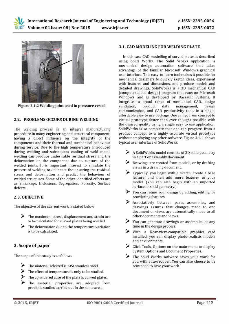
Figure 2.1.2 Welding joint used in pressure vessel
2.2. PROBLEMS OCCURS DURING WELDING The welding process is an integral manufacturing procedure in many engineering and structural component, having a direct influence on the integrity of the components and their thermal and mechanical behaviour during service. Due to the high temperature introduced during welding and subsequent cooling of weld metal, welding can produce undesirable residual stress and the deformation on the component due to rupture of the welded joints. It is important interest to simulate the process of welding to delineate the ensuring the residual stress and deformation and predict the behaviour of welded structures. Some of the other identified effects are as Shrinkage, Inclusions, Segregation, Porosity, Surface defects.
2.3. OBJECTIVE The objective of the current work is stated below
The maximum stress, displacement and strain are to be calculated for curved plates being welded.
The deformation due to the temperature variation is to be calculated.
3. Scope of paper The scope of this study is as follows
The material selected is AISI stainless steel.
The effect of temperature is only to be studied.
The considered case of the plate is curved plates.
The material properties are adopted from previous studies carried out in the same area.
3.1. CAD MODELING FOR WELDING PLATE
In this case CAD modelling of curved plates is described using Solid Works. The Solid Works application is mechanical design automation software that takes advantage of the familiar Microsoft Windows graphical user interface. This easy-to-learn tool makes it possible for mechanical designers to quickly sketch ideas, experiment with features and dimensions, and produce models and detailed drawings. SolidWorks is a 3D mechanical CAD (computer-aided design) program that runs on Microsoft Windows and is developed by Dassault Systems. It integrates a broad range of mechanical CAD, design validation, product data management, design communication, and CAD productivity tools in a single, affordable easy to use package. One can go from concept to virtual prototype faster than ever thought possible with the desired quality using a single easy to use application. SolidWorks is so complete that one can progress from a product concept to a highly accurate virtual prototype without employing any other software. Figure 3.1.1 shows typical user interface of SolidWorks.
A SolidWorks model consists of 3D solid geometry in a part or assembly document.
Drawings are created from models, or by drafting views in a drawing document.
Typically, you begin with a sketch, create a base feature, and then add more features to your model. (You can also begin with an imported surface or solid geometry.)
You can refine your design by adding, editing, or reordering features.
Associatively between parts, assemblies, and drawings assures that changes made to one document or views are automatically made to all other documents and views.
You can generate drawings or assemblies at any time in the design process.
With a Rear-view-compatible graphics card installed, you can display photo-realistic models and environments.
Click Tools, Options on the main menu to display System Options and Document Properties.
The Solid Works software saves your work for you with auto-recover. You can also choose to be reminded to save your work.
International Research Journal of Engineering and Technology (IRJET) e-ISSN: 2395-0056
Volume: 02 Issue: 08 | Nov-2015 www.irjet.net p-ISSN: 2395-0072
© 2015, IRJET ISO 9001:2008 Certified Journal Page 413
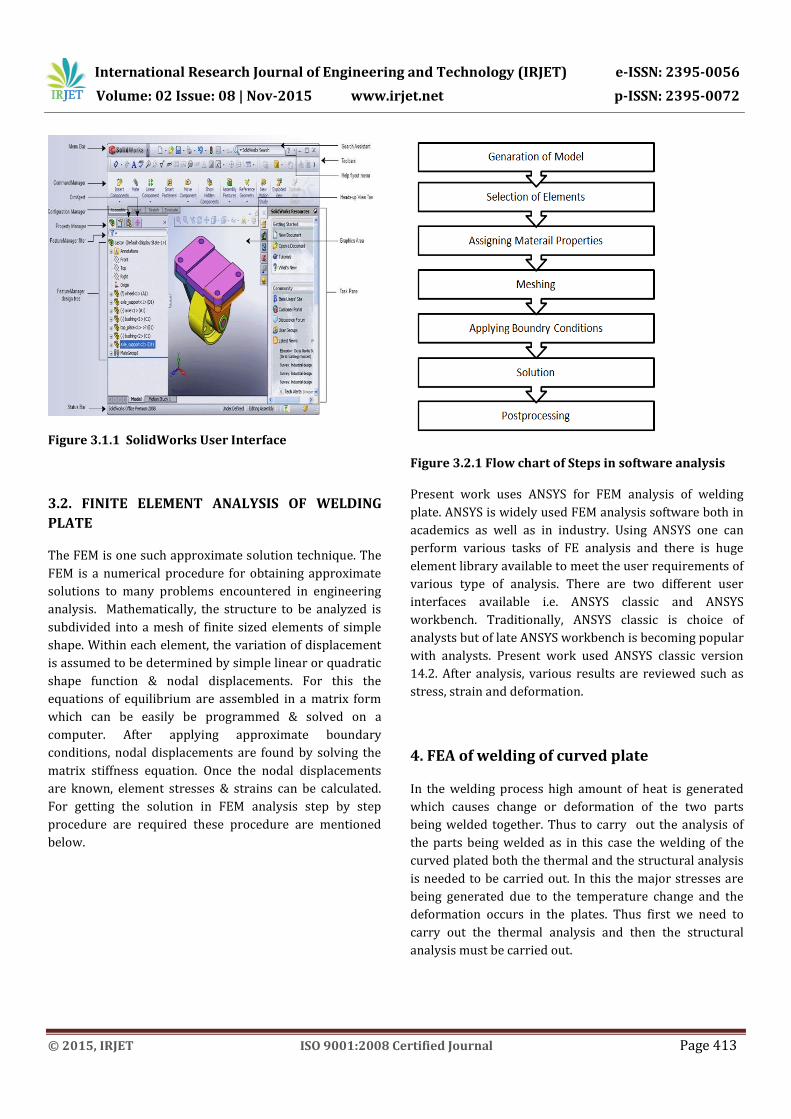
Figure 3.1.1 SolidWorks User Interface
3.2. FINITE ELEMENT ANALYSIS OF WELDING
PLATE
The FEM is one such approximate solution technique. The
FEM is a numerical procedure for obtaining approximate
solutions to many problems encountered in engineering
analysis. Mathematically, the structure to be analyzed is
subdivided into a mesh of finite sized elements of simple
shape. Within each element, the variation of displacement
is assumed to be determined by simple linear or quadratic
shape function & nodal displacements. For this the
equations of equilibrium are assembled in a matrix form
which can be easily be programmed & solved on a
computer. After applying approximate boundary
conditions, nodal displacements are found by solving the
matrix stiffness equation. Once the nodal displacements
are known, element stresses & strains can be calculated.
For getting the solution in FEM analysis step by step
procedure are required these procedure are mentioned
below.
Figure 3.2.1 Flow chart of Steps in software analysis
Present work uses ANSYS for FEM analysis of welding
plate. ANSYS is widely used FEM analysis software both in
academics as well as in industry. Using ANSYS one can
perform various tasks of FE analysis and there is huge
element library available to meet the user requirements of
various type of analysis. There are two different user
interfaces available i.e. ANSYS classic and ANSYS
workbench. Traditionally, ANSYS classic is choice of
analysts but of late ANSYS workbench is becoming popular
with analysts. Present work used ANSYS classic version
14.2. After analysis, various results are reviewed such as
stress, strain and deformation.
4. FEA of welding of curved plate
In the welding process high amount of heat is generated
which causes change or deformation of the two parts
being welded together. Thus to carry out the analysis of
the parts being welded as in this case the welding of the
curved plated both the thermal and the structural analysis
is needed to be carried out. In this the major stresses are
being generated due to the temperature change and the
deformation occurs in the plates. Thus first we need to
carry out the thermal analysis and then the structural
analysis must be carried out.
International Research Journal of Engineering and Technology (IRJET) e-ISSN: 2395-0056
Volume: 02 Issue: 08 | Nov-2015 www.irjet.net p-ISSN: 2395-0072
© 2015, IRJET ISO 9001:2008 Certified Journal Page 414
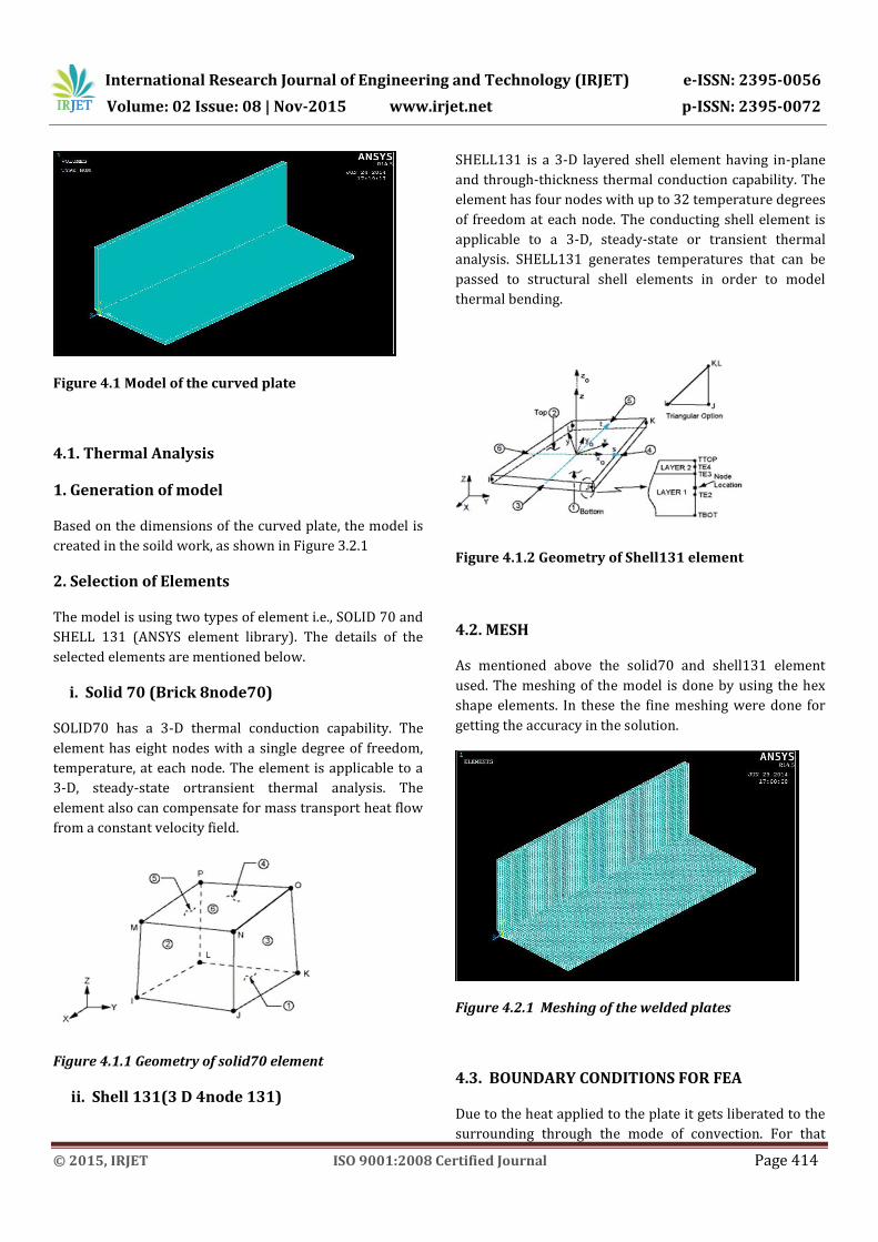
Figure 4.1 Model of the curved plate
4.1. Thermal Analysis
1. Generation of model
Based on the dimensions of the curved plate, the model is
created in the soild work, as shown in Figure 3.2.1
2. Selection of Elements
The model is using two types of element i.e., SOLID 70 and
SHELL 131 (ANSYS element library). The details of the
selected elements are mentioned below.
i. Solid 70 (Brick 8node70)
SOLID70 has a 3-D thermal conduction capability. The
element has eight nodes with a single degree of freedom,
temperature, at each node. The element is applicable to a
3-D, steady-state ortransient thermal analysis. The
element also can compensate for mass transport heat flow
from a constant velocity field.
Figure 4.1.1 Geometry of solid70 element
ii. Shell 131(3 D 4node 131)
SHELL131 is a 3-D layered shell element having in-plane
and through-thickness thermal conduction capability. The
element has four nodes with up to 32 temperature degrees
of freedom at each node. The conducting shell element is
applicable to a 3-D, steady-state or transient thermal
analysis. SHELL131 generates temperatures that can be
passed to structural shell elements in order to model
thermal bending.
Figure 4.1.2 Geometry of Shell131 element
4.2. MESH
As mentioned above the solid70 and shell131 element
used. The meshing of the model is done by using the hex
shape elements. In these the fine meshing were done for
getting the accuracy in the solution.
Figure 4.2.1 Meshing of the welded plates
4.3. BOUNDARY CONDITIONS FOR FEA
Due to the heat applied to the plate it gets liberated to the
surrounding through the mode of convection. For that
International Research Journal of Engineering and Technology (IRJET) e-ISSN: 2395-0056
Volume: 02 Issue: 08 | Nov-2015 www.irjet.net p-ISSN: 2395-0072
© 2015, IRJET ISO 9001:2008 Certified Journal Page 415
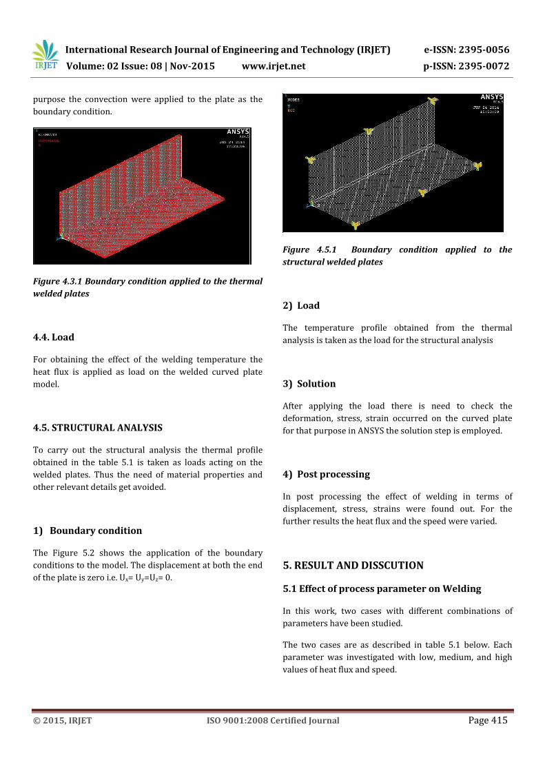
purpose the convection were applied to the plate as the
boundary condition.
Figure 4.3.1 Boundary condition applied to the thermal
welded plates
4.4. Load
For obtaining the effect of the welding temperature the
heat flux is applied as load on the welded curved plate
model.
4.5. STRUCTURAL ANALYSIS
To carry out the structural analysis the thermal profile
obtained in the table 5.1 is taken as loads acting on the
welded plates. Thus the need of material properties and
other relevant details get avoided.
1) Boundary condition
The Figure 5.2 shows the application of the boundary
conditions to the model. The displacement at both the end
of the plate is zero i.e. Ux= Uy=Uz= 0.
Figure 4.5.1 Boundary condition applied to the
structural welded plates
2) Load
The temperature profile obtained from the thermal
analysis is taken as the load for the structural analysis
3) Solution
After applying the load there is need to check the
deformation, stress, strain occurred on the curved plate
for that purpose in ANSYS the solution step is employed.
4) Post processing
In post processing the effect of welding in terms of
displacement, stress, strains were found out. For the
further results the heat flux and the speed were varied.
5. RESULT AND DISSCUTION
5.1 Effect of process parameter on Welding
In this work, two cases with different combinations of
parameters have been studied.
The two cases are as described in table 5.1 below. Each
parameter was investigated with low, medium, and high
values of heat flux and speed.
International Research Journal of Engineering and Technology (IRJET) e-ISSN: 2395-0056
Volume: 02 Issue: 08 | Nov-2015 www.irjet.net p-ISSN: 2395-0072
© 2015, IRJET ISO 9001:2008 Certified Journal Page 416
Table 5.1.1 Changing parameter of Heat flux and
Speed
Case Study Heat Flux Speed
1 Effect of Heat Flux Changed* Medium
2 Effect of Speed Medium Changed*
Thermo-mechanical responses such as residual stresses,
strains, and displacements were obtained from the finite
element elasto-plastic analysis. The responses were taken
along the vertical path and horizontal path. For all two
cases, the responses at each node along the path were
plotted over the nodes along the cross sections.
The following table represents the case of varying
parameters along horizontal path.
Table 5.1.2 Values of parameters
5.2 EFFECT OF HEAT FLUX
The change in the heat flux due to welding there is
considerable effect on the displacement, stress, elastic
strain and plastic strain along the vertical path and
horizontal path of the curved plate.
A. ALONG VERTICAL PATH
The parameters like displacement, stress, and strain
changes along the vertical path, are calculate and the
results of the same are discussed below.
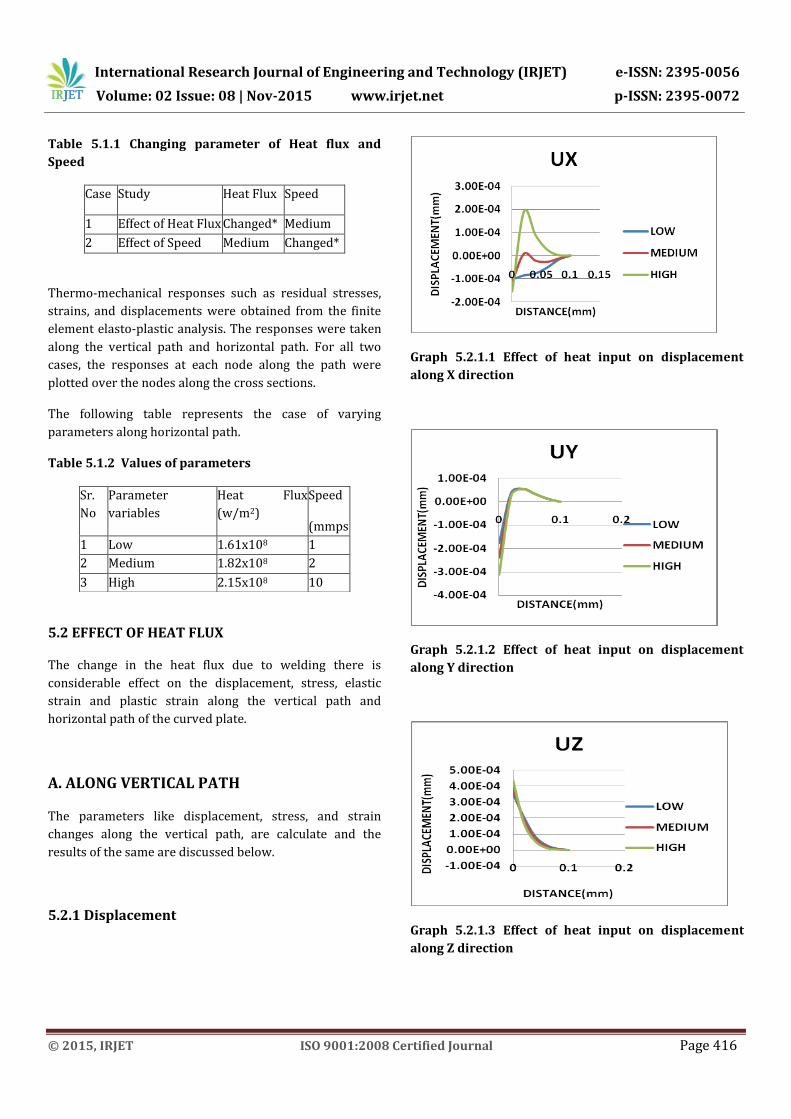
5.2.1 Displacement
Graph 5.2.1.1 Effect of heat input on displacement
along X direction
Graph 5.2.1.2 Effect of heat input on displacement
along Y direction
Graph 5.2.1.3 Effect of heat input on displacement
along Z direction
Sr.
No
Parameter
variables
Heat Flux
(w/m2)
Speed
(mmps
) 1 Low 1.61x10⁸ 1
2 Medium 1.82x10⁸ 2
3 High 2.15x10⁸ 10
International Research Journal of Engineering and Technology (IRJET) e-ISSN: 2395-0056
Volume: 02 Issue: 08 | Nov-2015 www.irjet.net p-ISSN: 2395-0072
© 2015, IRJET ISO 9001:2008 Certified Journal Page 417
As shown in figures 5.2.1.1, 5.2.1.2 and 5.2.1.3
displacements in X direction of the vertical plate is more
sensitive to heat input , from figure it is observed that
maximum displacement occurs at 30 mm cross section
which is in the heat affected zone. The displacement
obtained in the vertical path is more as compared to the
displacement in the horizontal path.
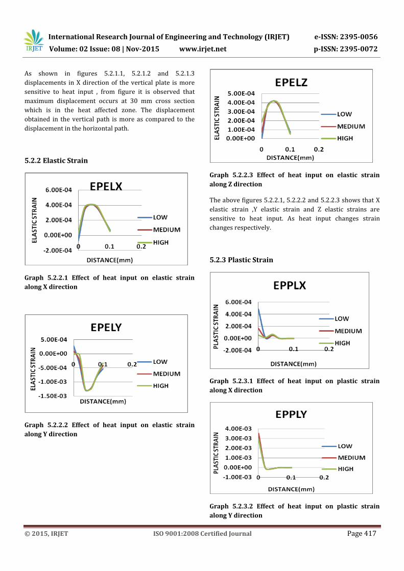
5.2.2 Elastic Strain
Graph 5.2.2.1 Effect of heat input on elastic strain
along X direction
Graph 5.2.2.2 Effect of heat input on elastic strain
along Y direction
Graph 5.2.2.3 Effect of heat input on elastic strain
along Z direction
The above figures 5.2.2.1, 5.2.2.2 and 5.2.2.3 shows that X
elastic strain ,Y elastic strain and Z elastic strains are
sensitive to heat input. As heat input changes strain
changes respectively.
5.2.3 Plastic Strain
Graph 5.2.3.1 Effect of heat input on plastic strain
along X direction
Graph 5.2.3.2 Effect of heat input on plastic strain
along Y direction
International Research Journal of Engineering and Technology (IRJET) e-ISSN: 2395-0056
Volume: 02 Issue: 08 | Nov-2015 www.irjet.net p-ISSN: 2395-0072
© 2015, IRJET ISO 9001:2008 Certified Journal Page 418
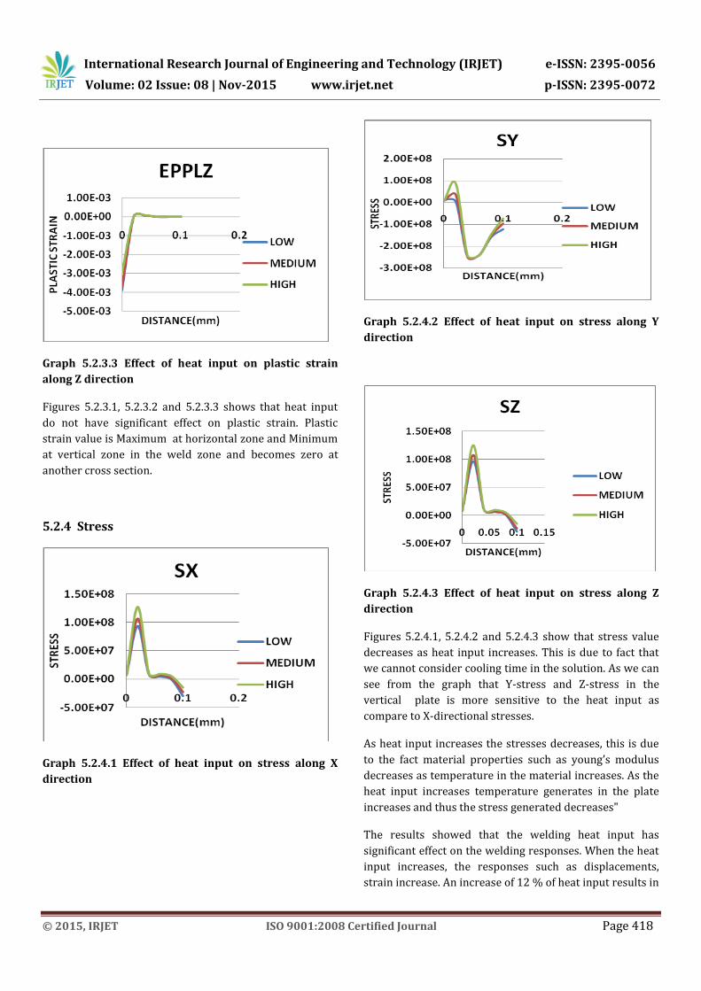
Graph 5.2.3.3 Effect of heat input on plastic strain
along Z direction
Figures 5.2.3.1, 5.2.3.2 and 5.2.3.3 shows that heat input
do not have significant effect on plastic strain. Plastic
strain value is Maximum at horizontal zone and Minimum
at vertical zone in the weld zone and becomes zero at
another cross section.
5.2.4 Stress
Graph 5.2.4.1 Effect of heat input on stress along X
direction
Graph 5.2.4.2 Effect of heat input on stress along Y
direction
Graph 5.2.4.3 Effect of heat input on stress along Z
direction
Figures 5.2.4.1, 5.2.4.2 and 5.2.4.3 show that stress value
decreases as heat input increases. This is due to fact that
we cannot consider cooling time in the solution. As we can
see from the graph that Y-stress and Z-stress in the
vertical plate is more sensitive to the heat input as
compare to X-directional stresses.
As heat input increases the stresses decreases, this is due
to the fact material properties such as young’s modulus
decreases as temperature in the material increases. As the
heat input increases temperature generates in the plate
increases and thus the stress generated decreases"
The results showed that the welding heat input has
significant effect on the welding responses. When the heat
input increases, the responses such as displacements,
strain increase. An increase of 12 % of heat input results in
International Research Journal of Engineering and Technology (IRJET) e-ISSN: 2395-0056
Volume: 02 Issue: 08 | Nov-2015 www.irjet.net p-ISSN: 2395-0072
© 2015, IRJET ISO 9001:2008 Certified Journal Page 419
a significant increase in the Z-displacement (8%), and X-
Elastic strain (60 %)and Z-Elastic strain (98 %).
5.3 Effect Of Speed
The change in the speed during welding has a considerable
effect on the displacement, stress, elastic strain and plastic
strain along the vertical path and horizontal path of the
curved plate. The detailed discussion will be carried out on
the effect of the speed below.
A. ALONG VERTICAL PATH
The parameters like displacement, stress, and strain
changes along the vertical path, are calculate and the
results of the same are given below.
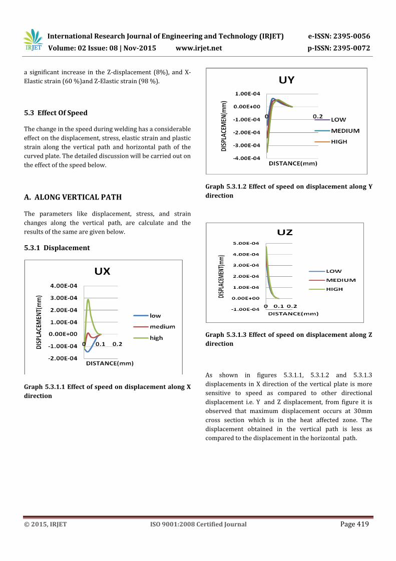
5.3.1 Displacement
Graph 5.3.1.1 Effect of speed on displacement along X
direction
Graph 5.3.1.2 Effect of speed on displacement along Y
direction
Graph 5.3.1.3 Effect of speed on displacement along Z
direction
As shown in figures 5.3.1.1, 5.3.1.2 and 5.3.1.3
displacements in X direction of the vertical plate is more
sensitive to speed as compared to other directional
displacement i.e. Y and Z displacement, from figure it is
observed that maximum displacement occurs at 30mm
cross section which is in the heat affected zone. The
displacement obtained in the vertical path is less as
compared to the displacement in the horizontal path.
International Research Journal of Engineering and Technology (IRJET) e-ISSN: 2395-0056
Volume: 02 Issue: 08 | Nov-2015 www.irjet.net p-ISSN: 2395-0072
© 2015, IRJET ISO 9001:2008 Certified Journal Page 420
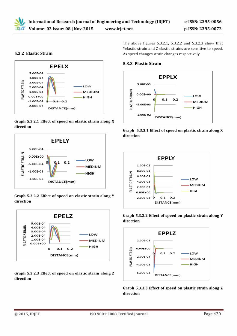
5.3.2 Elastic Strain
Graph 5.3.2.1 Effect of speed on elastic strain along X
direction
Graph 5.3.2.2 Effect of speed on elastic strain along Y
direction
Graph 5.3.2.3 Effect of speed on elastic strain along Z
direction
The above figures 5.3.2.1, 5.3.2.2 and 5.3.2.3 show that
Yelastic strain and Z elastic strains are sensitive to speed.
As speed changes strain changes respectively.
5.3.3 Plastic Strain
Graph 5.3.3.1 Effect of speed on plastic strain along X
direction
Graph 5.3.3.2 Effect of speed on plastic strain along Y
direction
Graph 5.3.3.3 Effect of speed on plastic strain along Z
direction
International Research Journal of Engineering and Technology (IRJET) e-ISSN: 2395-0056
Volume: 02 Issue: 08 | Nov-2015 www.irjet.net p-ISSN: 2395-0072
© 2015, IRJET ISO 9001:2008 Certified Journal Page 421
Figures 5.3.3.1, 5.3.3.2 and 5.3.3.3 shows that speed do not
have significant effect on plastic strain. Plastic strain value
is maximum in the weld zone and becomes zero at another
cross section.
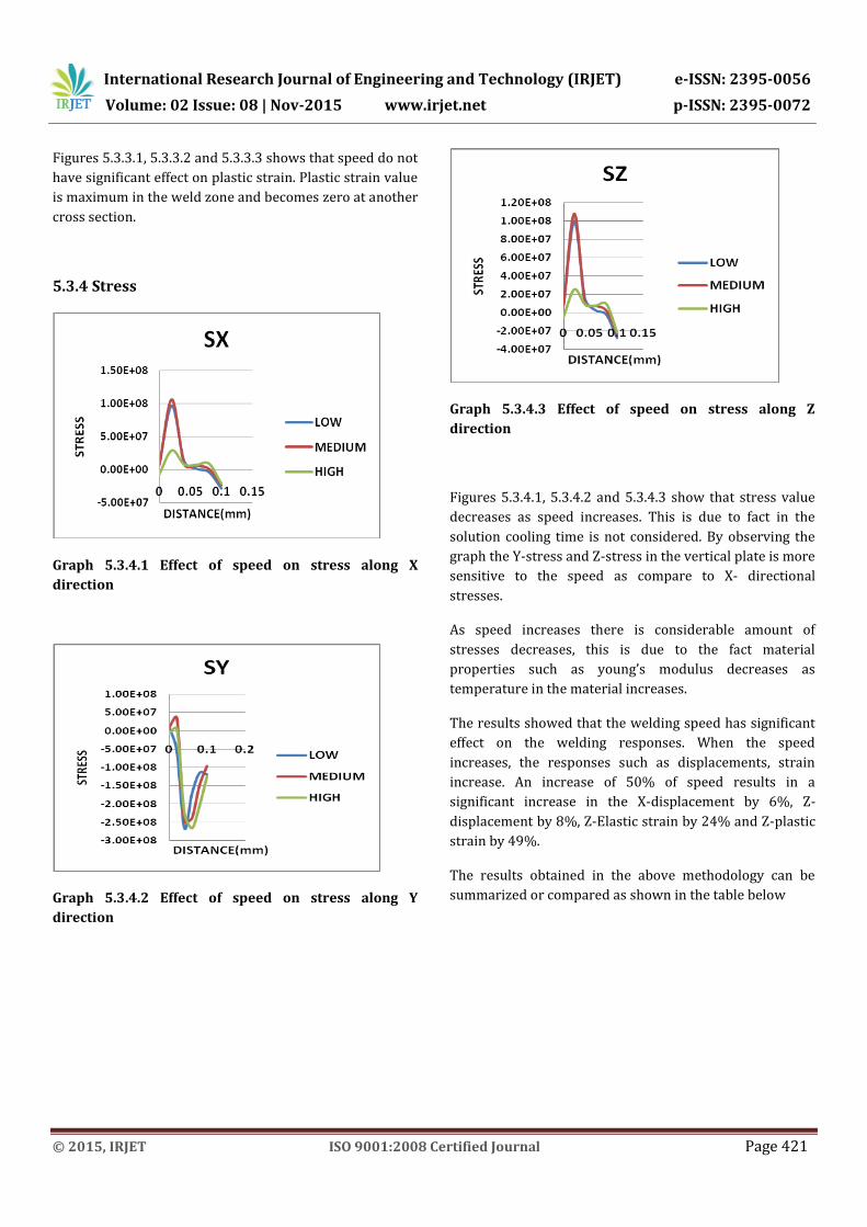
5.3.4 Stress
Graph 5.3.4.1 Effect of speed on stress along X
direction
Graph 5.3.4.2 Effect of speed on stress along Y
direction
Graph 5.3.4.3 Effect of speed on stress along Z
direction
Figures 5.3.4.1, 5.3.4.2 and 5.3.4.3 show that stress value
decreases as speed increases. This is due to fact in the
solution cooling time is not considered. By observing the
graph the Y-stress and Z-stress in the vertical plate is more
sensitive to the speed as compare to X- directional
stresses.
As speed increases there is considerable amount of
stresses decreases, this is due to the fact material
properties such as young’s modulus decreases as
temperature in the material increases.
The results showed that the welding speed has significant
effect on the welding responses. When the speed
increases, the responses such as displacements, strain
increase. An increase of 50% of speed results in a
significant increase in the X-displacement by 6%, Z-
displacement by 8%, Z-Elastic strain by 24% and Z-plastic
strain by 49%.
The results obtained in the above methodology can be
summarized or compared as shown in the table below
International Research Journal of Engineering and Technology (IRJET) e-ISSN: 2395-0056
Volume: 02 Issue: 08 | Nov-2015 www.irjet.net p-ISSN: 2395-0072
© 2015, IRJET ISO 9001:2008 Certified Journal Page 422
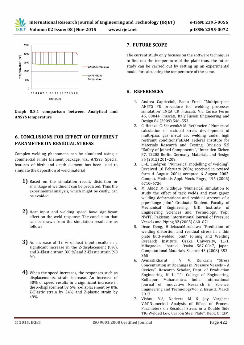
Graph 5.3.1 comparison between Analytical and
ANSYS temperature
6. CONCLUSIONS FOR EFFECT OF DIFFERENT
PARAMETER ON RESIDUAL STRESS
Complex welding phenomena can be simulated using a
commercial Finite Element package, viz., ANSYS. Special
features of birth and death element has been used to
simulate the deposition of weld material
1) Based on the simulation result, distortion or shrinkage of weldment can be predicted. Thus the experimental analysis, which might be costly, can be avoided.
2) Heat input and welding speed have significant effect on the weld response. The conclusion that can be drawn from the simulation result are as follows
3) An increase of 12 % of heat input results in a significant increase in the Z-displacement (8%), and X-Elastic strain (60 %)and Z-Elastic strain (98 %).
4) When the speed increases, the responses such as displacements, strain increase. An increase of 50% of speed results in a significant increase in the X-displacement by 6%, Z-displacement by 8%, Z-Elastic strain by 24% and Z-plastic strain by 49%
7. FUTURE SCOPE
The current study only focuses on the software techniques
to find out the temperature of the plate thus, the future
study can be carried out by setting up an experimental
model for calculating the temperature of the same.
8. REFERENCES
1. Andrea Capriccioli, Paolo Frosi. “Multipurpose ANSYS FE procedure for welding processes simulation”.ENEA CR Frascati, Via Enrico Fermi 45, 00044 Frascati, Italy,Fusion Engineering and Design 84 (2009) 546–553.
2. C. Heinze, C. Schwenk& M. Rethmeier .“ Numerical calculation of residual stress development of multi-pass gas metal arc welding under high restraint conditions”aBAM Federal Institute for Materials Research and Testing, Division 5.5 ‘‘Safety of Joined Components’’, Unter den Eichen 87, 12205 Berlin, Germany. Materials and Design 35 (2012) 201–209.
3. L.-E. Lindgren “Numerical modelling of welding”. Received 18 February 2004; received in revised form 4 August 2004; accepted 6 August 2005. Comput. Methods Appl. Mech. Engrg. 195 (2006) 6710–6736
4. M. Abid& M. Siddique “Numerical simulation to study the effect of tack welds and root gapon welding deformations and residual stresses of a pipe-flange joint” Graduate Student, Faculty of Mechanical Engineering, GIK Institute of Engineering Sciences and Technology, Topi, NWFP, Pakistan. International Journal of Pressure Vessels and Piping 82 (2005) 860–871
5. Dean Deng, HidekazuMurakawa “Prediction of welding distortion and residual stress in a thin plate butt-welded joint” Joining and Welding Research Institute, Osaka University, 11-1, Mihogaoka, Ibaraki, Osaka 567-0047, Japan. Computational Materials Science 43 (2008) 353–365
6. AvinashKharat , V. V. Kulkarni “Stress Concentration at Openings in Pressure Vessels – A Review”. Research Scholar, Dept. of Production Engineering, K. I. T.‟s College of Engineering, Kolhapur, Maharashtra, India. International Journal of Innovative Research in Science, Engineering and TechnologyVol. 2, Issue 3, March 2013
7. Vishnu V.S, Nadeera M & Joy Varghese V.M“Numerical Analysis of Effect of Process Parameters on Residual Stress in a Double Side TIG Welded Low Carbon Steel Plate”. Dept. Of CIM,
International Research Journal of Engineering and Technology (IRJET) e-ISSN: 2395-0056
Volume: 02 Issue: 08 | Nov-2015 www.irjet.net p-ISSN: 2395-0072
© 2015, IRJET ISO 9001:2008 Certified Journal Page 423
T.K.M College of engg./ Kerala University, India. IOSR Journal of Mechanical and Civil Engineering (IOSR-JMCE) e-ISSN: 2278-1684, p-ISSN: 2320-334X PP 65-68
8. Wenge Zhang , Xuedong Chen, Tiecheng Yang, Jianrong Li & Jilin Yu “Stress analysis and safety assessment for nozzle welding area enduringhigh pressure and high temperature”.Department of Mechanics and Mechanical Engineering, University of Science and Technology of China, Hefei 230027, Anhui, China.Journal of Pressure Equipment and Systems 4 (2006) 86-90.
9. B. Brickstad”, B. L. Josefsonb “A parametric study of residual stresses in multi-pass butt-welded stainlesssteel pipes”.International Journal of Pressure Vessels and Piping 75 (1998) 1 l-25.
10. Ho-Sung Lee, Jong-Hoon Yoon, Jae-Sung Park “A study on failure characteristic of spherical pressure vessel”.KSLV Technology Division, Korea Aerospace Research Institute, 45 Eoeun-Dong, Yuseong-Gu, Daejeon, 305-333, Republic of Korea.Journal of Materials Processing Technology 164–165 (2005) 882–888.
11. Harshal B Sonawane,E R Deore “FINITE ELEMENT MODEL FOR THE EFFECT OF HEAT INPUT & SPEED ON RESIDUAL STRESS “. International Journal of Mechanical Engineering Robotics and Research, Volume 3, Issue-3, july 2015.
12. D.Devakumar, D. B Jabaraj “Research on Gas Tungsten Arc Welding ofStainless Steel – An Overview”.International Journal of Scientific & Engineering Research, Volume 5, Issue 1, January-2014 1612ISSN 2229-551.
BIOGRAPHIES .
Prof Vijay L Kadlag completed his Master degree in Mechanical (Production) and presently working as Professor and HOD of workshop at the Department of Mechanical of SVIT COE CHINCHOLI-42210 , Maharashtra (INDIA). His research interest includes Mechanical Design, FEA, and Pressure Vessel Design etc
Kiran D Gaidhane is a M.E (Design Engineering) Pursuing from SVIT COE CHINCHOLI-42210, Maharashtra (INDIA). He is having overall 7 year experience in Automobile Industry .His major interests are in Manufacturing Science, Production Engg , Fabrication, welded structures