
A 3d CFD-CEM Methodology for Simulating Industrial Scale Packed Bed Chemical Looping Combustion...
18
A 3D CFD-DEM Methodology for Simulating Industrial Scale Packed Bed Chemical Looping Combustion Reactors Mandar V. Tabib, Stein T. Johansen, and Shahriar Amini* Flow Technology Group, SINTEF Materials and Chemistry, Trondheim 7034, Norway ABSTRACT: Design of industrial scale packed bed reactors can be aided by using computational fluid dynamics (CFD)-discrete element method (DEM) simulation for understanding the transport phenomena. However, conducting CFD-DEM simulation for the whole large-scale packed bed reactor is computationally prohibitive, which limits the usage of this tool. Hence, a methodology has been developed to identify the segments of the bed, which can serve as a good representative for the CFD simulation of large industrial scale packed bed reactors. Two segments, a cylindrical cut-segment and a wall-segment, have been used to represent the core central region of packed bed and the near wall region of packed bed, respectively. The methodology determines the size (diameter and height) of the cylindrical bed cut-segment that can be a good representative for the large-scale packed bed reactor. The segments are then used to obtain the information on transport phenomena (friction factor coefficients (pressure drop) and the heat transfer/mass-transfer coefficients) for packed beds made of spherical particles and non-spherical particles. CFD simulations have been conducted on the DEM generated packing segments for a wide particle Reynolds number range (from laminar to turbulent regime) to develop the correlations. The proposed methodology (on cut-segment and wall- segment) has been validated for spherical particle packed bed by comparing results to well-established correlations (such as Ergun equation for pressure drop, Wakao correlation and multiparticle Ranz−Marshal correlation for particle heat transfer coefficient, and Dixon−Lubua and Colledge−Paterson correlation for wall heat transfer coefficient). The methodology is then applied to understand the transport phenomena and to develop correlations for long cylindrical pellet (aspect ratio 7) and fluted- ring. The pressure drop correlation obtained for the long cylindrical pellet (aspect ratio of 7) packed bed has been compared to the correlation for cylindrical pellet with aspect ratio of 5.77 (obtained by Nemec; Nemec, D.; Levec, J. Chem. Eng. Sci. 2005, 60, 6947). The comparison shows that the effect of increasing aspect ratio on pressure drop is captured as per the expected trend. The methodology has been applied in a chemical looping combustion reactor based on the pressure drop and heat transfer results. Thus, the proposed CFD-DEM methodology offers a computationally efficient way of understanding the transport phenomena in an industrial scale reactor through simulating a methodically selected segment inside the reactor. This enables design and performance assessment of such reactors. 1. INTRODUCTION The packed bed chemical looping combustion (CLC) reactor has been envisaged as a cost-effective technology for trans- forming hydrocarbons into energy along with CO 2 capture. 1−4 The packed bed CLC process involves the utilization of the redox chemistry of a transition metal in a cyclic operation. The transition metal oxide acts as an oxygen carrier and forms the fixed packing of the packed bed reactor. This fixed packing is alternatively exposed to fuel gas stream (reduction cycle) and air streams (oxidation cycle). When exposed to the fuel gas stream (syngas), the metal oxide reduces. This reduction cycle results in production of hot stream of carbon dioxide and superheated steam, which can be used for energy generation. The reduced metal oxide bed is then exposed to the air stream, which reoxidizes it. This exothermic oxidation cycle produces a stream of hot gas that can also be used for energy production. The reduction−oxidation cycle is then repeated continuously leading to power generation and CO 2 capture (CO 2 isolated by condensing steam). The ease of scale-up of packed bed reactors offers a possible early rollout for its use at commercial scale, provided the technology is first shown to be feasible at a lower scale of operation. This work aims to contribute to the design and development of such a technology by developing a methodology for proper understanding of the transport phenomenon within the packing structure of a packed bed reactor. The packing structure can have significant effect on the pressure drop, the heat transfer, and the mass transfer characteristics of the system. Traditionally, these critical parameters required for the designing of packed bed reactors are obtained using empirical correlations (such as Ergun, 5 Eisfeld, 6 and Nemec 1 for obtaining pressure drop; multiparticle Ranz and Marshal; 7,38 Li and Finlayson 8 and Dixon 9 for obtaining heat transfer coefficient; Leva 10 and Dixon 11 for computing void fraction). However, some of these correlations are valid only for certain operating conditions and for known particle shapes, such as Ergun is valid for spherical particles packing with tube to diameter ratio greater than 5. Nemec 1 has modified Ergun correlation for different particle shapes, but the correlations are valid for cylindrical pellets up to aspect ratio of 5.77. Similarly, Ranz and Marshal’s 7,38 heat transfer correlation is valid for spherical particles packing; while Li and Finlayson’s 8 heat transfer correlation for cylindrical pellets is valid up to particle Reynolds number of 800. Thus, every correlation has its range of applicability. In recent times, novel packed bed Received: July 30, 2012 Revised: June 8, 2013 Accepted: June 11, 2013 Published: June 11, 2013 Article pubs.acs.org/IECR © 2013 American Chemical Society 12041 dx.doi.org/10.1021/ie302028s | Ind. Eng. Chem. Res. 2013, 52, 12041−12058
-
Upload
davidvaca9 -
Category
Documents
-
view
43 -
download
4
Transcript of A 3d CFD-CEM Methodology for Simulating Industrial Scale Packed Bed Chemical Looping Combustion...

A 3D CFD-DEM Methodology for Simulating Industrial Scale PackedBed Chemical Looping Combustion ReactorsMandar V. Tabib, Stein T. Johansen, and Shahriar Amini*
Flow Technology Group, SINTEF Materials and Chemistry, Trondheim 7034, Norway
ABSTRACT: Design of industrial scale packed bed reactors can be aided by using computational fluid dynamics (CFD)-discreteelement method (DEM) simulation for understanding the transport phenomena. However, conducting CFD-DEM simulationfor the whole large-scale packed bed reactor is computationally prohibitive, which limits the usage of this tool. Hence, amethodology has been developed to identify the segments of the bed, which can serve as a good representative for the CFDsimulation of large industrial scale packed bed reactors. Two segments, a cylindrical cut-segment and a wall-segment, have beenused to represent the core central region of packed bed and the near wall region of packed bed, respectively. The methodologydetermines the size (diameter and height) of the cylindrical bed cut-segment that can be a good representative for the large-scalepacked bed reactor. The segments are then used to obtain the information on transport phenomena (friction factor coefficients(pressure drop) and the heat transfer/mass-transfer coefficients) for packed beds made of spherical particles and non-sphericalparticles. CFD simulations have been conducted on the DEM generated packing segments for a wide particle Reynolds numberrange (from laminar to turbulent regime) to develop the correlations. The proposed methodology (on cut-segment and wall-segment) has been validated for spherical particle packed bed by comparing results to well-established correlations (such asErgun equation for pressure drop, Wakao correlation and multiparticle Ranz−Marshal correlation for particle heat transfercoefficient, and Dixon−Lubua and Colledge−Paterson correlation for wall heat transfer coefficient). The methodology is thenapplied to understand the transport phenomena and to develop correlations for long cylindrical pellet (aspect ratio 7) and fluted-ring. The pressure drop correlation obtained for the long cylindrical pellet (aspect ratio of 7) packed bed has been compared tothe correlation for cylindrical pellet with aspect ratio of 5.77 (obtained by Nemec; Nemec, D.; Levec, J. Chem. Eng. Sci. 2005, 60,6947). The comparison shows that the effect of increasing aspect ratio on pressure drop is captured as per the expected trend.The methodology has been applied in a chemical looping combustion reactor based on the pressure drop and heat transferresults. Thus, the proposed CFD-DEM methodology offers a computationally efficient way of understanding the transportphenomena in an industrial scale reactor through simulating a methodically selected segment inside the reactor. This enablesdesign and performance assessment of such reactors.
1. INTRODUCTIONThe packed bed chemical looping combustion (CLC) reactorhas been envisaged as a cost-effective technology for trans-forming hydrocarbons into energy along with CO2 capture.
1−4
The packed bed CLC process involves the utilization of theredox chemistry of a transition metal in a cyclic operation. Thetransition metal oxide acts as an oxygen carrier and forms thefixed packing of the packed bed reactor. This fixed packing isalternatively exposed to fuel gas stream (reduction cycle) andair streams (oxidation cycle). When exposed to the fuel gasstream (syngas), the metal oxide reduces. This reduction cycleresults in production of hot stream of carbon dioxide andsuperheated steam, which can be used for energy generation.The reduced metal oxide bed is then exposed to the air stream,which reoxidizes it. This exothermic oxidation cycle produces astream of hot gas that can also be used for energy production.The reduction−oxidation cycle is then repeated continuouslyleading to power generation and CO2 capture (CO2 isolated bycondensing steam). The ease of scale-up of packed bed reactorsoffers a possible early rollout for its use at commercial scale,provided the technology is first shown to be feasible at a lowerscale of operation. This work aims to contribute to the designand development of such a technology by developing amethodology for proper understanding of the transportphenomenon within the packing structure of a packed bed
reactor. The packing structure can have significant effect on thepressure drop, the heat transfer, and the mass transfercharacteristics of the system. Traditionally, these criticalparameters required for the designing of packed bed reactorsare obtained using empirical correlations (such as Ergun,5
Eisfeld,6 and Nemec1 for obtaining pressure drop; multiparticleRanz and Marshal;7,38 Li and Finlayson8 and Dixon9 forobtaining heat transfer coefficient; Leva10 and Dixon11 forcomputing void fraction). However, some of these correlationsare valid only for certain operating conditions and for knownparticle shapes, such as Ergun is valid for spherical particlespacking with tube to diameter ratio greater than 5. Nemec1 hasmodified Ergun correlation for different particle shapes, but thecorrelations are valid for cylindrical pellets up to aspect ratio of5.77. Similarly, Ranz and Marshal’s7,38 heat transfer correlationis valid for spherical particles packing; while Li and Finlayson’s8
heat transfer correlation for cylindrical pellets is valid up toparticle Reynolds number of 800. Thus, every correlation has itsrange of applicability. In recent times, novel packed bed
Received: July 30, 2012Revised: June 8, 2013Accepted: June 11, 2013Published: June 11, 2013
Article
pubs.acs.org/IECR
© 2013 American Chemical Society 12041 dx.doi.org/10.1021/ie302028s | Ind. Eng. Chem. Res. 2013, 52, 12041−12058

chemical looping combustion reactors and many industrial scalepacked bed reactors are using/testing some unique catalystshapes (such as high aspect ratio cylindrical pellet and flutedring particle) at stringent reactor operating conditions (such asparticle Reynolds number from 760 to 1500, 20 bar pressure,1000 K). The currently available empirical correlations (asmentioned above) will not be valid in such cases. When theparticle shape and size change, the packing structure (particleorientation and porosity) will change, and this will change thetransport phenomenon within the bed. In such circumstances,computational fluid dynamics (CFD)-discrete element method(DEM) can provide a cost-effective way of understanding thetransport phenomena in the random packing structure of thepacked bed. This is especially crucial, as it is difficult or time-consuming to conduct experiments under such conditions andobtain appropriate correlations. Here, the DEM has been usedto generate the random packing structure of the fluted ringparticles and the high aspect ratio cylindrical pellets. The CFDis then conducted on the DEM generated packing structure tounderstand the transport phenomena. However, the use ofCFD-DEM model for simulating large-scale industrial reactors(tube to particle diameter ratio greater than 40) is computa-tionally prohibitive. Hence, to meet our aims of aiding thedesign of packed bed reactor using CFD-DEM model, a newmethodology needs to be developed and new correlations needto be obtained that can be used as closure by a simplified 1Dmodel for designing. Hence, the current work aims to addressthese issues by meeting the following objectives:(a) Developing a methodology to overcome the difficulties in
the simulation of flow in the packed bed containing a hugenumber of particles. The current work aims to put forward anew methodology, involving the use of two segments: acylindrical bed-segment with slip wall boundary condition(CBS-SW) for studying pressure drop and particle heat transferand a wall-segment approach for studying wall heat transfercoefficient. To be sure that the selected bed-segment is goodrepresentation of the industrial scale packed bed reactor, themethodology focuses on obtaining suitable dimensions of thebed-segment (diameter and height of the segment). Thevalidation of methodology will be done by using a sphericalparticle where established correlations are available forcomparison.(b) Developing correlations by understanding the transport
phenomena: The proposed methodology will demonstrate itsability to obtain information on transport phenomena (frictionfactor (pressure drop) and heat transfer coefficient) for uniqueparticle shapes (fluted ring and long-aspect ratio cylindricalpellets), which will also allow for design of packed bed reactorusing a simplified and faster 1D model.(c) Enabling comparison of pellet shapes: To demonstrate
that the understanding of transport phenomena (the flowprofiles, the heat transfer, and the pressure drop) gained by useof proposed CFD-DEM methodology can enable comparisonof different packing structure (cylindrical pellet packing andfluted ring packing) for design purposes.The development of this methodology has wider application
as it encourages a potential “serial by simplification” multiscalemodeling approach, wherein the correlation obtained by 3DCFD-DEM model on a representative volume of the packedbed is plugged into the 1D model to design the reactor. Thismethodology can also be in general applied to study differenttypes of packings (such as trilobe, quadrulobe, monoliths,
wagon wheels, hollow extrudates, discs) for which thecorrelations are not available in literature.To highlight the uniqueness of our proposed novel CFD-
DEM methodology and how this work fills some newknowledge gaps, a brief literature review is presented below.
2. LITERATURE REVIEWIn literature, several notable contributions have been madetoward understanding the transport phenomena in the packedbed using CFD for simplified geometry. One of the constraintsin enabling CFD-DEM simulation of packed bed is thelimitation with generating the computational mesh for thecomplex packing geometry. A fine mesh is required to capturethe flow in the voidage, and the contact points between theparticles and particle-wall have to be treated to avoid skewedcells. The huge meshing requirement limits the geometry sizethat can be simulated. To enable modeling, researchers haveincorporated simplifications to the sophisticated packed bedstructure, and have come up with some notable contributions inthis field. The simplifications involve: (a) use of effectiveporous medium in place of actual particle packing for bothsingle phase and multiphase flows.12−14 The porous mediaconcept has been popularly used to design packed beds as it iscomputationally efficient. However, the porous media conceptdoes not consider the solid phase to be made up of discreteparticles but only as an effective phase with a defined voidfraction. The void fraction distribution is provided as an inputwith additional terms implemented in the momentum balanceto allow for the additional resistance to flow. For meeting ourcurrent objectives of accurately characterizing the effect of aparticular particle shape on pressure drop and heat transfercoefficient, this approach may not be suitable. (b) Anothersimplified approach applies the assumption of a quasi-homogeneous reactor model, which involves the heat transferand dispersion to be lumped.15 The lumping of transportprocesses conceals much physical phenomena, and this needsthe introduction of an effective viscosity for the bed forobtaining agreement between computed and experimentalvelocity profiles. Hence, this approach may not be applicablefor our work. (c) Researchers from Dixon’s group16−20 pointedout that it would be better to use the geometry of particlepacking, and they have made some major notable contributionsby taking this approach. Because of computational constrains,they simplified the actual packing structure, by use of wall-segment section as a representative of the entire geometry andby use of structured packing or a predefined arrangement ofparticles in place of actual random packing. Dixon’s group haveused a periodic 120° wall-segment model with symmetry sidecondition to understand the phenomena in vessels with a lowtube to particle diameter ratio of 4. Here, the packing structureis arranged in a manner as observed by them frequently in theirstudy of cylindrical pellets in a tube. However, in most realsituations, the randomly generated packing structure (com-prised of nonspherical particle shapes) may not lead to arepeatable pattern or any frequently seen arrangement. Hence,the use of periodic boundaries might not be possible for ourcase. (d) Recently, the DEM has been used to generate a veryrealistic packing structure.21 Bai22 used DEM to obtain thespherical particle and cylindrical pellet packing in their lab-scale,low tube-to-particle diameter vessel and used this for their CFDsimulation. Others too have successfully used this approachwith simple spherical particles at low tube-to-particlediameter.23,24 However, for large-scale packed bed reactors
Industrial & Engineering Chemistry Research Article
dx.doi.org/10.1021/ie302028s | Ind. Eng. Chem. Res. 2013, 52, 12041−1205812042

(with expected high tube-to-particle diameter ratio of around40) involving nonspherical particles, it will be computationallyprohibitive to generate mesh even for a smaller wall-segment asthe walls are 40dp distance away. Also, in such cases, the actualwall effect of vessel can be neglected as the wall effect isconfined to a smaller region (up to 3−5dp from wall). In suchcases, the methodology presented in this work involving thecylindrical bed-segment with slip wall boundary condition(CBS-SW) can be widely used for studying the pressure drop inlarge-scale industrial packed bed reactors. For obtaining nearwall information in an industrial scale reactor, a wall-segmentcan be constructed up to 3−5 particle diameter from the wall.This has also been attempted in this work by obtaining the wallheat transfer coefficient. The section below explains themethodology, which is followed by details of simulationparameters and discussion on results.
3. METHODOLOGY FOR ENABLING SIMULATION OFTHE LARGE-SCALE PACKED BED CLC REACTOR
The methodology determines the size of the bed cut-segmentthat can be a good representative for the large-scale reactor,which can enable meshing and the CFD simulations to beconducted. The bed cut-segment is a concentric cylindrical cut-section of size diameter (D*) and height (H*) carved out ofthe entire DEM generated packing bed (of diameter D andheight H) (see Figure 1 for schematic representation). Thefollowing steps are carried out to select the bed-segment sizeD* and H*:
(a) First, discrete element modeling (DEM) is used togenerate the packing structure for a given catalyst shape. Thenonspherical catalyst shapes (such as cylinder pellet and flutedring particle) are generated by using a multisphere model,where the locations of spheres are determined through a userdefined script. Figure 2 shows the cylindrical pellet and flutedring particle formed out of multiple spheres. The details ofDEM simulations and particle sizes used in actual simulationare given in Tables 1 and 2. The simulation of the fillingprocess becomes computationally prohibitive as the number ofparticles increases. So, the vessel dimensions for DEMgenerated packing (i.e., D and H) are fixed out of constraintsarising from computational requirements. The diameter D ofthe vessel for DEM generated packing is taken as 15 times the
equivalent particle diameter (D = 15dp) for spherical pellets and10 times the equivalent particle diameter (D = 10dp) forcylindrical and fluted ring packing. The vessel height H is takenas 1.5−2 times the diameter D (or H = 15dp − 20dp) for all.Figure 3 shows the packing structure obtained for sphericalparticle, cylindrical pellets, and fluted ring using the DEM. Thevalidation of DEM generated packing is done by measuringporosity and is covered in section 4.(b) Next, a cylindrical cut-section size has to be chosen as the
bed-segment for CFD analysis. The cut-segment is cut out fromthe DEM generated packing. The CFD simulation applies a slipwall boundary condition (zero shear stress boundary condition)to the side cylindrical surfaces of the cylindrical cut-segment,while the top and bottom planar surfaces are the inlet andoutlet boundary conditions, respectively. The details of theCFD simulation parameters and meshing details are given insection 4 and Tables 3 and 4. Figures 4−6 show the cut-segment and wall-segment for the spherical particle packing, thefluted ring packing, and the cylindrical pellet packing,respectively. A decision has to be made about the minimumsize that can be a good representative. Hence, the diameter(D*) and height (H*) of the concentric-cylindrical cut-segmentare varied, and CFD is conducted to analyze the variation in thepressure profile. Initially, the height H* is taken as 8dp, and D*
Figure 1. Schematic of DEM generated packing structure and the bed-segment cut-section from it.
Figure 2. Particle shape generated using multiple spheres using scripts:(A) cylindrical pellets (aspect ratio: 7, sphericity 0.65), and (B) flutedring (aspect ratio: 1.4).
Table 1. Simulation Details and Particle Size
particle dimensionsfluted ringparticle cylindrical pellet
sphericalparticle
average external diameter(mm)
12.4 3.6
average length (mm) 17.3 24.9equivalent particle diameter(dp, mm)
13.86 7.4 10
Table 2. DEM Parameters Used in the Study
DEM parametersfluted ring/
cylindrical pellet spherical pellet
model to simulate particle collisionsand motion
Hertz−Mindlinmodel
Hertz−Mindlinmodel
particle density 2300 kg/m3 2300 kg/m3
shear modulus, N/m2 1 × 10⁸ 1 × 10⁸
Poissons ratio 0.25 0.25local damping coefficient 0.7 0.7particle−particle and particle−wallfriction coefficient
0.3 0.4
Industrial & Engineering Chemistry Research Article
dx.doi.org/10.1021/ie302028s | Ind. Eng. Chem. Res. 2013, 52, 12041−1205812043

is taken in increments of half particle diameter (2dp, 2.5dp, and3dp). The H* value should be such that the bed has asubstantial developed flow region devoid of the entrance effects.The height of bed-segment H* is selected on the basis of howmany particle diameters are required to overcome the entranceeffects of particles. This is determined from the axial profile ofthe cross-section area averaged pressure. The flow is said to bedeveloped when the pressure drop varies linearly with the axiallocation. Figure 7 shows the averaged pressure profile for threedifferent diameters (2dp, 2.5dp, and 3dp) for cylindrical packing(Figure 7A), for fluted ring packing (Figure 7B), and forspherical packing (Figure 7C). The pressure profile is seen tobe getting stabilized within one particle diameter. Hence, aminimum bed-segment height (H*) of 4dp will be sufficient asit has flow regions free of entrance effect. Next, the diameter ofcylindrical bed-segment (D*) is selected. D* is selected so thatthe pressure drop per unit length (in regions free of entranceeffect) is stabilized and stops varying with diameter D*, andalso the effect of wall region is avoided. The pressure drop perunit length [(ΔP/L)D*] obtained for each diameter D* isplotted versus the diameter D* to see when it stops varying (orwhen the profile becomes flat). Figure 8A−C shows the slope(pressure drop per unit length) in the developed and entranceeffect free region for three different cut-segment diameters forthe fluted ring packing (Figure 8A), the cylindrical pelletpacking (Figure 8B), and the spherical packing (Figure 8C).The obtained slope (pressure drop per unit length) then isplotted versus the diameter D* as in Figure 9. For all of thepackings, it can be seen that pressure drop stabilizes after 2.5dpparticle diameters. Also, as per the literature, for sphericalpellets, the effect of wall is felt upon the void fractionoscillations up to 3−5 particle diameters from the wall.21
However, for cylindrical pellets and nonspherical, the radialvoid fraction shows less oscillation near wall and gets stabilizedby 3 particle diameters from the wall (faster than the sphericalpellets) as seen the in results by Giese.33 So, for avoiding thewall region, the maximum cut-segment diameter D* should be5dp (D − (2*5dp) = 15dp − 10dp = 5dp) for spherical pellets,and for cylinder and fluted ring packing, the maximum D*should be 4dp ((D − (2*3dp) = 10dp − 6dp = 4dp). Thus, theselected cut-segment diameter is away from the wall-regioneffect. Also, further checking for larger cut-segment diameterthan 3dp is needless as with increasing size the meshing ofgeometry becomes prohibitive due to excessive use of computerresources. Thus, a cylindrical cut-segment dimension ofdiameter D* = 3dp and height H* = 4dp can give a good andaffordable representation of a large-scale reactor. On the basisof this experience, a wall-segment of 3.5dp width (in radialdirection) and 4dp height has been selected for studiespertaining to study of near wall effect. The wall-segmentregion is expected to capture the near wall physics moreaccurately.(c) The D* and H* decided on the basis of above
calculations are used to obtain pressure drop and heat transfercoefficients for the large-scale CLC reactor. Several simulationshave been conducted using this cut-segment dimension toobtain the pressure drop and heat transfer correlation fordifferent particle Reynolds numbers (varied from Rep = 1.75 to1540), and correlations have been proposed. These correlationsare useful for the prediction and scale-up of the industrial scalepacked bed reactors. The correlations obtained are discussedlater in this Article.The next section describes the CFD-DEM tools and the
simulation parameters used to implement this methodology.
Figure 3. DEM generated packing for (A) spherical particle, (B) cylindrical pellets packing, and (C) fluted ring packing.
Table 3. Meshing Details for Grid Used in the Study
meshing parameters fluted ring/cylindrical pellet spherical pellet
mesh type tetrahedral mesh element for fluted ring (Figure 5) and Cartesian cut-cellfor cylinder (Figure 6)
tetrahedral mesh element (Figure 4)
mesh size for cut-segmentcase 1: 2dp diameter vessel approx. 1 million cells approx. 0.3 million cellscase 2: 2.5dp diameter vessel approx. 1.7 million cells approx. 1.55 million cellscase 3: 3dp diameter vessel approx. 2.2 million cells approx. 2.83 million cells
mesh size for wall-segment 0.32 million cells 0.33 million cells and 0.39 millioncells
particle treatment for avoiding skewed cells ingrid generation
particle is shrunk by 2% neighboring spheres are bridged bya cylinder
Industrial & Engineering Chemistry Research Article
dx.doi.org/10.1021/ie302028s | Ind. Eng. Chem. Res. 2013, 52, 12041−1205812044

4. VALIDATION AND IMPLEMENTATION DETAILS OFMETHODOLOGY
4.1. DEM Simulation. a. Implementation. A Packed bed isgenerated by simulating the filling process of particles in thevessel. This can be enabled by using the DEM numericalmethod, which tracks the motion of each particle in free fallunder gravity and its dynamic interactions/collisions with otherparticles and boundaries. The force arising during theinteractions/collisions leads to newer particle positions andnewer particle velocities, and is computed using the forcedisplacement law. This particle contact behavior is simulatedusing a soft particle model involving springs, dashpots, andfrictional sliders. In the soft particle model, the rigid particlesare allowed to overlap at contact points. The magnitude of theoverlap is related to the contact force via the force−displacement law. All overlaps are small in relation to particlesizes. The spring expresses the hardness of particles throughYoung’s modulus parameter, while the dampener or dashpotexpresses the particle energy dissipation through the coefficientof restitution parameter. The friction sliders expressing thefriction between contact points are defined with a Columbictype of friction and implemented with a friction factor. Theseparameters are based on physical properties of the materialconstituting the particle and the wall boundary. Tables 1 and 2outline the parameter used in DEM simulation of cylindricaland fluted ring packed bed. The commercial DEM softwarepackage PFC3D by ITASCA25 has been used in this work.PFC3D allows for implementation of arbitrary shape ofparticles using the clump logic feature. The arbitrary shapeparticle is formed from multiple spheres, which are clubbed toform a clump (Figure 2). A user-defined script is written forcreating the particle shape. The script computes the locationand number of spheres when the user inputs the dimensions ofthe particle and the size of a sphere. The higher number ofsphere would lead to more accurate particle shape, but it willalso lead to computational costs while running DEM. Themultisphere particle (or clump) behaves as a rigid body (i.e.,the particles comprising the clump remain at a fixed distancefrom each other), although they can have a deformableboundary. Thus, they will not break apart, irrespective of theforces acting upon it. Particles within a clump may overlap toany extent, and the contact forces are not generated betweenthese particles. During the calculation cycle, the contactsinternal to the clump are ignored, resulting in a savings ofcomputer time. However, contacts with particles external to theclump are considered. Such contacts develop when the particlescomprising the boundary of a clump come into contact withother particles. At each cycle, a multisphere particle position isgenerated randomly within the vessel. To save computationaltime for the filling process, the particles are not generated attop of vessel but at random locations within vessel. The initialvelocity of the multisphere particle (clump) is assigned on thebasis of its axial location and its potential and kinetic energy.The calculation cycle in PFC3D is a time stepping algorithmthat requires the repeated application of the law of motion toeach particle, a force−displacement law to each contact, and aconstant updating of the wall positions. The time-step is chosenso small that, during a single time-step, disturbances cannotpropagate further from any particle than its immediateneighbors. At all times, the forces acting on any particle thenare determined exclusively by its interaction with the particleswith which it is in contact. Because the speed at which aT
able
4.CFD
Param
etersUsedin
theStud
y
CFD
parameters
particleReynoldsnumber
Re pfisvariedfrom
turbulentregime(Re p
f=1520)to
laminar
region
(Re p
f=7)
fordeveloping
pressure
drop
correlations
forfluted
ringandcylindricalpelletsandsphericalpellets
fluidandproperties
airandits
propertiesarecomputedat
20bar,1000
Kforallcut-segm
ents,exceptforwall-segmentstudy(w
here
thermalconductivity
ofairistakenas
0.0242
W/m
2 ·K)
inletboundary
condition
forwall-segment
andcut-segm
ent
massflow
rateperunitarea
isvariedto
achievedesiredReynoldsnumber;hence,foreach
case
(2d p,3d p,3.5d p
having
differentcut-segm
entdiam
eters),the
massflow
ratechangesas
thecross-sectionalarea
availableforflow
changeswith
thecut-sectionsize;inlettemperature
ofairis300K
outletboundary
condition
forwall-
segm
entandcut-segm
ent
oneatmosphere(absolute)
staticpressure
outerwall/side
wallboundary
conditions
forcut-segm
ent,theonlyside
wallisspecified
ashaving
slip
wall(zeroshearstress)andaconstant
temperature
of1000
Kforwall-segment,theouterwallisno-slip
boundary
andtherestof
theside-wallsareslipwallboundary;twocaseshave
been
studied,onewith
constant
temperatureof
1000
Katside
wallsandsecond
with
azero
heat
flux
boundary
condition
atside
wall
particlewallboundary
conditionsforwall-
segm
entandcut-segm
ent
no-slip
mom
entum
andaconstant
temperature
of1000
K
turbulence
model
realizablek-εmodelwith
standard
wallfunctio
ntim
estep
5×10
−5s
Industrial & Engineering Chemistry Research Article
dx.doi.org/10.1021/ie302028s | Ind. Eng. Chem. Res. 2013, 52, 12041−1205812045

disturbance can propagate is a function of the physicalproperties of the discrete system, so the time-step can bechosen based on the system. PFC3D uses a simplified way of
computing the time-step by viewing the system as comprised ofmultiple bodies (masses) and springs (stiffness). It computesthe critical time step for each body in the system. The critical
Figure 4. (A,B) Two cut-segments of spherical particle packed bed: (A) 2dp diameter and 10dp height segment, (B) 3dp diameter and 4dp height. (C)The wall-segment used for obtaining the wall heat transfer coefficient. The three figures in (B) and (C) show the outer surface of cut-section, theparticles inside the cut-section, and the mesh used for CFD.
Figure 5. Fluted ring packing bed-segment cut-sections (2dp diameter and 8dp height). The diameter and height of this cut-section are varied as permethodology. The outer surface of cut-section and the particles inside the cut-section are shown on the left. The mesh used is shown on the rightside.
Industrial & Engineering Chemistry Research Article
dx.doi.org/10.1021/ie302028s | Ind. Eng. Chem. Res. 2013, 52, 12041−1205812046

time-step is a function of mass of the body and spring(stiffness) associated with the contacts of the body. Thestiffnesses are estimated by summing the contribution from allcontacts, using only the diagonal terms of the contact stiffnessmatrix. The final critical time step is taken to be the minimumof all critical timesteps computed for all degrees of freedom ofall bodies. The readers can refer to the PFC3D manual25 for themathematical implementation of this scheme, as well as workby Cundall.26 Once the packing structure of the packed bed ispredicted with DEM, the locations of particles in packingstructure are transferred into the GAMBIT meshing softwareusing script.b. Validation of DEM Simulation Results. Figure 3A shows
the DEM obtained spherical packed bed for a vessel with adiameter around 15 times the particle diameter (D/dp = 15).The global porosity of this DEM generated spherical bedpacking has been measured to be around 0.404, which is similarto the value obtained using Dixons correlation32 for bulkvoidage for spherical bed packing. The porosity has beenobtained at the center of the DEM generated bed using themeasured sphere tool in PFC3D software. The cut-segmentrepresenting the core central region of the bed has this porosity(0.404). The porosity in the whole wall-segment is around 0.44,which is higher than the 0.405 porosity in the core region. Thisis in line with the near wall porosity reported by Zhang,34 whosuggested that the porosity value is about 5% higher than bulkporosity at near wall region (of up to 2 particle diameters fromthe wall). This suggests that the setting of DEM parameter forparticle−particle friction coefficient and particle−wall frictioncoefficient (both around 0.4, see Table 2) is appropriate for the
present case. The friction coefficient can have an impact onporosity and bed structure; for example, when the frictioncoefficient is high, then the particle will get balanced on eachother and counteract the gravity. So, a higher friction coefficientwould cause a loose packing (leading to higher porosity). Thebulk porosity is accurate in this case, and DEM generated bedcan be considered for further studies. For fluted ring andcylindrical pellets, the particle and ball friction of 0.3 is used.Generally, a value higher than spherical particles can beexpected as nonspherical particles are expected to have a higherrolling friction at walls. However, one can expect some maskingof the friction effects in these nonspherical cases because of theinterlocking due to surface resolution. With the current frictioncoefficient, the DEM generated packing was generated forcylindrical pellets at different aspect ratios (not shown here).The DEM was able to capture the trend that with increasingaspect ratio, the porosity was seen to be increasing (as reportedby Nemec1). The resultant porosity for the cylindrical pellet ofaspect ratio (AR = 2) is around 0.42, and for a higher aspectratio of 7, this is around 0.55. The result is similar to that citedby Nemec1 in his work for an aspect ratio of 2.
4.2. CFD Simulation. 4.2.1. Implementation. Computa-tional fluid dynamics solves the conservation equations formomentum, mass, and energy using a finite volume method.Ansys Fluent 13 has been used for this CFD simulation. Toenable CFD simulation for the complex packing geometry, themesh has to be created on the complex packing structure. Theregions of particle contact points and sharp angles at cut-section may often cause some skewed cells to appear. Theoccurrence of skewed cells leads to divergence of the solver. To
Figure 6. Cylindrical packing bed-segment cut-sections (2dp diameter and 8dp height) for pressure drop computation in (A) and the wall-segmentfor wall heat transfer coefficient in (B). The diameter and height of this cut-segment are varied as per methodology. The outer surface of sections, theparticles inside the sections, and the mesh used are shown.
Industrial & Engineering Chemistry Research Article
dx.doi.org/10.1021/ie302028s | Ind. Eng. Chem. Res. 2013, 52, 12041−1205812047

overcome this, there are four methods suggested in theliterature. Bai22 and Atmakidis and Kenig30 suggested shrinkingthe particles by a certain amount to remove the contact points.The shrinking of the particles increases the porosity, for which acorrection factor has to be taken into account while computingpressure drop. Guardo24 suggested increasing the size of theparticles by a certain value. The contact points then becomecontact areas, and the skewness of the cells is reduced. Thismethod needs also a correction factor for pressure drop.Eppinger23 suggested flattening of the particles locally in theproximity of the contact points if the distance between twoparticle surfaces falls below a predefined value. This leads to asmall gap between the particles, which can be filled with cells ofgood quality. Ookawara28 suggested bridging the sphericalparticles with small cylinders if the distance between theparticles falls below a predefined value, and the macroscopicflow properties such as the pressure drop are not influenced bythis. This bridged cylinder method has been adopted in thiswork for spherical particles, while for nonspherical particles, weshrink the particle size to enable meshing. However, becausethe geometry is so complex, we had to shrink the particle byabout 2% to enable good quality mesh generation. A tetrahedralgrid was used for the fluted ring packing, and a Cartesian cut-cell grid was used for the cylindrical and spherical particlepacking (as seen in Figures 5 and 6). In both the cases, a Y+ ofaround 3 is obtained near the particle surface. The mesh size,boundary conditions, and simulation parameters for CFDsimulations at three different diameters (2dp, 2.5dp, and 3dp) fordifferent particle shapes are given in Tables 3 and 4. The
particle shrinkage affects the voidage, which can affect thepressure drop results. To account for this effect, the pressuredrop results are rescaled with void-fraction (using term ⌈ε3/1 −ε⌉) in accordance with Ergun’s5 finding. From the CFD results,the pressure drop correlation and heat transfer coefficientcorrelation have been obtained in the equation form as shownbelow.
4.2.1.1. Equation for Pressure Drop (Friction Factor)Correlation. The dimensionless pressure drop (friction factor)correlation has been proposed in two forms: a linear Ergunequation form (eq 1) and in the form of equation proposed byDalla Valle31 (eq 2).
ρ=
Δ ε− ε
= +⎡⎢⎢
⎤⎥⎥f
PD
L VA
ReB
11
pp
3
s2
pm (1)
where A is known as the Blake−Kozeny−Carman constant andB is known as the Burke−Plummer constant. The Ergunequation above is used in validation of the proposedmethodology for pressure drops in spherical particles packingin regions away from the wall using A = 150 and B = 1.75. Forfluted ring and cylindrical pellet shapes, the Ergun equation ismodified by changing values of A and B parameters. Theseparameters are determined by fitting eq 1 to the results fromthe CFD-DEM methodology for these particle shapes.For the equation proposed by Dalla Valle31 (eq 2):
Figure 7. Axial profile of cross-section area averaged pressure fordifferent cut-segment diameters for fluted ring, cylindrical pellets, andspherical particle packing.
Figure 8. Slope (pressure drop per unit length) computed in thedeveloped region for the three different diameters for fluted ring,cylindrical pellets, and spherical particle.
Industrial & Engineering Chemistry Research Article
dx.doi.org/10.1021/ie302028s | Ind. Eng. Chem. Res. 2013, 52, 12041−1205812048

ρ=
Δ ε− ε
= + +⎡⎢⎢
⎤⎥⎥f
PD
L VA
ReB
ReC
11
pp
3
s2
pm pm (2)
where A, B, and C are the parameters that are determined byfitting the equation to CFD-DEM methodology results. Vs issuperficial velocity, and Repm is modified particle Reynoldsnumber (varied from 3800 to 1.75 for establishing thecorrelation).In both equations, the modified particle Reynolds number is
computed as:
ρμ
=− ε
ReV D
(1 )pms p
(3)
4.2.1.2. Equation for Heat Transfer Correlation. Theparticle heat transfer coefficient has been used in the formgiven by Ranz−Marshal and Wakao37 (eq 4):
= = +Nuh d
kARe Pr2.0 x y
pp p
p (4)
where Rep is the particle Reynolds number based on relativevelocity. Ranz−Marshal proposed the parameters for a singlesphere to be A = 0.6, x = 0.5, and y = 0.33. They later studied amultiparticle spherical packing and determined A to be 1.8 forpacked bed. Wakao accounted for the effect of axial thermal andmodified the Ranz−Marshal correlation by suggesting A to be1.1 and x to be 0.6. Both Wakao and Ranz−Marshalcorrelations have been used in validation of the proposedmethodology for obtaining particle heat transfer coefficient inspherical particle packing. For fluted ring and cylindrical pelletshapes, eq 4 is modified by changing values of A. Theseparameters are determined by fitting eq 4 to the results fromthe CFD-DEM methodology for these particle shapes.The wall heat transfer coefficient has been proposed in the
form of eq 5 (originally given by Li and Finlayson).
= =Nuh d
kARe x
ww p
pf (5)
where A, x, and y are the parameters that are determined byfitting the equation to results of CFD CFD-DEM methodologyin cylindrical pellets; Pr is the Prandtl number (Pr = μCp/k),and Repf is particle Reynolds number based on the superficialvelocity. For validation of wall heat transfer coefficient using theCFD-DEM methodology, the correlations proposed by Dixon−Lubua and Colledge−Paterson have been used. The particleheat transfer coefficient (hp) and wall heat transfer coefficient(hw) needed to develop the above correlations are computedfrom the CFD results using heat flux at particle surfaces and atwall and the average bulk temperature.
a. Average Particle Heat Transfer Coefficient.
∫∫
∫∫
=·
·−
=hq S
S T TT
T V
V
d
d1
(, where
d
dp,averagep
p p bulk)bulk
(6)
q is the heat flow rate per unit particle surface area (W/m2)obtained from CFD results, Sp represents all particle surfaceelements (faces), and V represents all fluid volume cells.
Figure 9. Slope (pressure drop per unit length) from Figure 7 versusthe diameter of bed-segment for (A) fluted ring, (B) cylindrical pellet,and (C) spherical particle.
Figure 10. Mesh and geometry used for validation of fluent for computing drag coefficient over a single spherical particle.
Industrial & Engineering Chemistry Research Article
dx.doi.org/10.1021/ie302028s | Ind. Eng. Chem. Res. 2013, 52, 12041−1205812049

b. Wall Heat Transfer Coefficient.
∫∫
∫∫
=·
·−
=hq S
S T TT
T V
V
d
d1
(, where
d
dw,averagew
w p bulk)bulk
(7)
q is the heat flow rate per unit area (W/m2) obtained fromCFD results, Sw represents all wall surface elements, and V is forall fluid volume cells.c. Validation. The CFD method is first validated on the
single sphere particle and then on the spherical particle packedbed at low tube-to-particle diameter. The CFD-DEM cut-segment methodology is validated on the spherical particlepacking (where established correlations are available forcomparison), and then the methodology is applied fordeveloping correlations for unique particle shapes.4.2.1.3. Validation of Drag Coefficient for Single Spherical
Particle. The drag coefficients predicted by the 3D CFD forsingle sphere particle provide a fair agreement with thoseobtained by Morsi−Alexander correlation.27 Figure 10 showsthe geometry and planar cut-section of the spherical particle (ofdiameter dp = 6 mm) inside a box (wind-tunnel of dimension:10dp × 10dp × 10dp) meshed with the Cartesian cut-cellapproach. The CFD simulates the air flow over the stationaryspherical particle (as in a wind-tunnel), and the dragexperienced by the particle is obtained. The inlet air flow ratecorresponds to the particle Reynolds number to be studied.The boundary condition at outlet is specified to be at oneatmosphere (absolute) static pressure. The side walls of the boxhave zero shear stress (slip wall) boundary condition togenerate the effect of far-away region, and the spherical particleinside the box (wind-tunnel) is a no-slip wall. In Figure 10A,the spherical particle diameter to grid size ratio (dp/ΔX) is 5,and in Figure 10B, this ratio is 10 (finer grid, Y+ of around 0.5−1 at high Reynolds number of 6000). Table 4 and Figure 11
show the drag coefficient obtained at different Reynoldsnumber. The coarser grid (dp/ΔX = 5) has given less than3% deviation in drag prediction for Reynolds number up to600, but at Re = 6000, the deviation is 16.7% (shown inparentheses in Table 4) as compared to that predicted byMorsi−Alexander correlation.27 The finer grid (dp/ΔX = 10)has been used at higher Reynolds number of 6000 and resultsin lower deviation of 5.89%. This could be because at higherReynolds number, the boundary layer thickness reduces andflow undergoes separation. Hence, a finer grid is used to resolve
the boundary layer and to capture the boundary layer physicsand the resulting form and skin drag more accurately.
4.2.1.4. Validation of Pressure Drop in Spherical ParticlePacked Bed. The pressure drop computed for spherical particlepacked bed is validated with the Eisfeld equation6 for pressuredrop. DEM has been used to generate the packing structure(Figure 12) and to enable good mesh at contact points; abridged cylinder approach28,29 is used to treat the contactpoints as seen in Figure 12. A Cartesian-cut-cell mesh has beenused. The Eisfeld correlation6 has been chosen for comparisonas it considers the influence of the tube-to-particle diameterratio and therefore the influence of the confining walls on thepressure drop. Table 5, Figure 12, and Figure 13 show that thedeviation between CFD and Eisfeld predicted pressure drop isbetween 7% and 10% for the three Reynolds numbers (Re =2532, 4302, and 5061). The Reynolds has been chosen suchthat the turbulence regime is encountered. The CFD uses thek-ε turbulence model based on results in the literature.22,23 Theagreement between CFD and Eisfeld correlation has been quitegood. The results do not change much with use of a finer grid,thus ensuring grid independence of results. The goodagreements obtained with CFD for drag computation of singlespherical particle and for pressure drop in spherical packed bedgive us the confidence to go ahead for applying it with differentparticle shapes.
4.2.1.5. Validation of Cut-Segment Methodology forSpherical Packing. The spherical packing packed bed hasbeen chosen for validation of methodology as establishedcorrelations are available for comparison. The pressure dropresults obtained using the cut-segment are validated bycomparing it with the Ergun correlation for pressure drop.Further, a separate wall-segment approach has been used forobtaining the wall heat transfer coefficient in the near wallregion. The results of wall heat transfer coefficient have beenvalidated with the Dixon and Labua35 correlation and theColledge−Paterson correlation.36 The results on the particleheat transfer coefficient have been validated with theestablished multiparticle Ranz−Marshal correlation andWakao correlation for packed bed.The pressure drop has been computed at different Reynolds
numbers varying from laminar regime to turbulent regime(Table 6). Figure 14 shows the pressure and the velocity profileat two particle Reynolds numbers (Rep 760 and Rep 380).Figure 15 compares the prediction of pressure drop obtained byCFD on a cut-segment (with mesh size of 0.39 million nodes)and Ergun correlation. The simulations were also conducted atslightly coarser mesh of 0.33 million nodes to check for gridindependence at a particle Reynolds number of 350. Thepressure drop results did not vary much. The deviation fromErgun is within 5% for Reynolds number lower than 350.However, at the higher Reynolds number of 750, the CFDunderpredicts the pressure drop by around 13% as compared toErgun correlation. The current results can be consideredreasonably accurate to validate the use of cut-segmentmethodology for pressure drop studies. The cut-segmentmethodology is used to conduct thermal studies as well. Theidea is to check whether it can be used to predict the particleand wall heat transfer coefficient. The thermal boundarycondition of constant specified temperature on the segment slipwall (zero shear stress wall) is not consistent as it suggests thatthe heat transfer is allowed on this boundary while themomentum flux is zero. Hence, a proper validation is requiredto check whether this thermal boundary condition will affect
Figure 11. Comparison of the drag coefficient as predicted by CFDand obtained by Morsi−Alexander at different Reynolds number.
Industrial & Engineering Chemistry Research Article
dx.doi.org/10.1021/ie302028s | Ind. Eng. Chem. Res. 2013, 52, 12041−1205812050

the region of interest and physics adversely. The cut-segment ofspherical packed bed is validated for predicting the wall andparticle heat transfer coefficient using the Dixon−Labua35
correlation and the Colledge−Paterson36 correlation. Thevalidation results pertaining to pressure drop correlations(hydrodynamics) do not change by simulating the cut-segmentboth with and without thermal calculations. This is mostlybecause the flow properties are not changed due to thermalcalculations; hence, the pressure drop results are not affected bythe thermal boundary condition. However, the wall heattransfer coefficient value obtained from the cut-segment showsan overprediction of around 60% as compared to theColledge−Paterson36 correlation at a particle Reynolds numberof 750. This could be because the cut-segment has slip wallboundary condition (where the wall heat transfer coefficient ismeasured). As a result of this slip wall boundary condition, thehydrodynamic boundary layer does not exist, and there is ahigher convection. This higher convection results in over-prediction of wall heat transfer coefficient. Thus, the cut-segment with slip wall boundary leads to inaccurate near wallphysics. Also, the region near the slip wall does not have as highporosity as the regions near the actual wall, because this slipwall is actually a part of the cut-segment of the central region ofthe packed vessel. Hence, to obtain an accurate wall heattransfer coefficient, a wall-segment approach has been tested(see Figure 4C). More importantly, the outer wall of this wall-segment, where the wall heat transfer is to be computed, has ano-slip wall with a specified constant temperature boundarycondition. The inlet boundary condition for the wall-segment isspecified by a mass-flow rate. The boundary condition at outletis specified to be at one atmospheric (absolute) static pressure.We limit the wall-segment up to 3.5 particle diameter from thewall resulting in a inner wall surface. The boundary at this innerwall-surface and two other side-wall surfaces is specified to be aslip wall boundary with a zero heat flux boundary condition.Another wall-segment simulation case has been set up to testthe effect of thermal boundary condition. Here, the boundarycondition at inner wall and the two side surface has beenchanged to constant temperature boundary condition, while therest is kept the same. The wall-segment region has 4% moreporosity than the cut-segment zone (which is as observed byZhang34). The mesh size for the wall-segment is around 1.07
Figure 12. Pressure drop obtained by applying CFD over the DEM generated spherical particle packing (extreme left) at three different Reynoldsnumbers (Re of 2532, 4302, and 5061). The Cartesian mesh and bridged cylinder approach used can be seen at second from left.
Table 5. Comparison of Drag Coefficient Predicted by CFDand Morsi−Alexander for a Flow over Spherical Particle
Reynoldsnumber
drag coefficient predictedby Morsi−Alexander
CFD predicteddrag coefficient % deviation
0.006 4000 4103 2.5%60 1.36 1.33 2.2%600 0.52 0.51 2.73%6000 0.39 0.36 (0.46) 5.89% (16.7%)
Figure 13. Comparisons of pressure drop as predicted by CFD and asobtained by Eisfeld at three different Reynolds numbers (Re of 2532,4302, and 5061).
Table 6. Pressure Drop Deviation from Flow over SphericalParticle Packed Bed
Reynoldsnumber
Eisfeld (2001) predictedpressure drop (Pa)
CFD predictedpressure drop (Pa) % deviation
2532 2194 2383 7.94302 6106 6780 9.95062 8415 9353 10
Industrial & Engineering Chemistry Research Article
dx.doi.org/10.1021/ie302028s | Ind. Eng. Chem. Res. 2013, 52, 12041−1205812051

million nodes with the average Y+ at outer wall around 3 at aparticle Reynolds number of 760. Figure 16 shows the wall-segment heat transfer coefficient obtained from the CFD study.CFD results have been compared to that predicted by Dixon−Labua35 correlation and Colledge−Paterson36 correlation attwo particles Reynolds numbers (Rep 760 and Rep 580). Figure14C,D shows the temperature and velocity profile obtained atthese two Reynolds numbers. Figures 16 and 17 compare theCFD prediction of the wall heat transfer coefficient and theparticle heat transfer coefficient with established correlations. Itwas seen that by varying the boundary condition from constanttemperature to zero heat flux at Rep of 750, the wall heattransfer coefficient result did not change appreciably (only by3−5%). The CFD predicted results underpredicts by 6% ascompared to predictions by Colledge−Paterson36 correlation,and it overpredicts by around 15% as compared to the Dixon−Labua35 correlation. This wall heat transfer coefficient result forthe wall-segment is better than that predicted by the cut-
segment with slip outer wall (where 60% overprediction isobserved). This could be because the physics of heat transfernear the outer wall is accurately captured in the wall-segmentsimulation. It can be said that the boundary condition at outer-wall (where wall heat transfer coefficient is measured) will havea significant effect on the wall heat transfer coefficient. Whilethe inner wall and side wall’s boundary condition influences thebulk fluid temperature, it does not have much influence on theheat transfer mechanism near the outer wall. Thus, the wall-segment approach is a suitable approach for obtaining the wallheat transfer coefficient.For obtaining particle heat transfer coefficient, both of the
segments (wall-segment and cut-segment) have been used. Theparticle heat transfer coefficient obtained from CFD over cut-segment (see Figure 17A) overpredicts by around 5−15%((hCFD − hcorrelation)/hCFD) as compared to the Wakao and
Figure 14. (A,B) Pressure and velocity profiles at Reynolds number 760 and 380 for the cut-segment of spherical packing, and (C,D) show thetemperature and velocity profile for heat transfer studies at Re 760 and 570.
Figure 15. Validation of methodology: Comparison of CFD predictedpressure drop for cut-segment of spherical particle packing with thepressure drop predicted by the Ergun correlation.
Figure 16. Validation of methodology: Comparison of CFD predictedwall-heat transfer coefficient for wall-segment of spherical particlepacking with the wall-heat-transfer-coefficient predicted by theColledge and Paterson correlation36 and Dixon−Labua.35
Industrial & Engineering Chemistry Research Article
dx.doi.org/10.1021/ie302028s | Ind. Eng. Chem. Res. 2013, 52, 12041−1205812052
multiparticle Ranz−Marshal correlation at low Reynoldsnumber (Re ≤ 200). However, as the Reynolds numberincreases, the CFD begins to underpredict as compared to
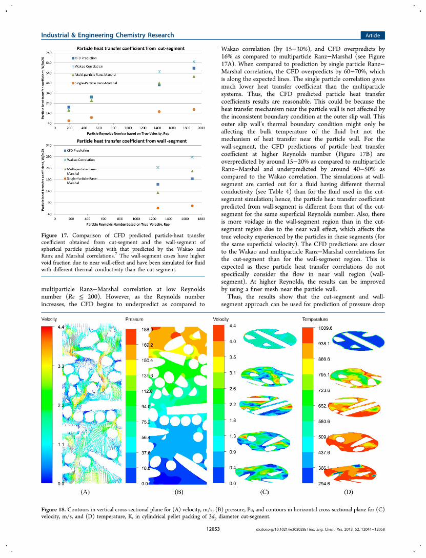
Wakao correlation (by 15−30%), and CFD overpredicts by16% as compared to multiparticle Ranz−Marshal (see Figure17A). When compared to prediction by single particle Ranz−Marshal correlation, the CFD overpredicts by 60−70%, whichis along the expected lines. The single particle correlation givesmuch lower heat transfer coefficient than the multiparticlesystems. Thus, the CFD predicted particle heat transfercoefficients results are reasonable. This could be because theheat transfer mechanism near the particle wall is not affected bythe inconsistent boundary condition at the outer slip wall. Thisouter slip wall’s thermal boundary condition might only beaffecting the bulk temperature of the fluid but not themechanism of heat transfer near the particle wall. For thewall-segment, the CFD predictions of particle heat transfercoefficient at higher Reynolds number (Figure 17B) areoverpredicted by around 15−20% as compared to multiparticleRanz−Marshal and underpredicted by around 40−50% ascompared to the Wakao correlation. The simulations at wall-segment are carried out for a fluid having different thermalconductivity (see Table 4) than for the fluid used in the cut-segment simulation; hence, the particle heat transfer coefficientpredicted from wall-segment is different from that of the cut-segment for the same superficial Reynolds number. Also, thereis more voidage in the wall-segment region than in the cut-segment region due to the near wall effect, which affects thetrue velocity experienced by the particles in these segments (forthe same superficial velocity). The CFD predictions are closerto the Wakao and multiparticle Ranz−Marshal correlations forthe cut-segment than for the wall-segment region. This isexpected as these particle heat transfer correlations do notspecifically consider the flow in near wall region (wall-segment). At higher Reynolds, the results can be improvedby using a finer mesh near the particle wall.Thus, the results show that the cut-segment and wall-
segment approach can be used for prediction of pressure drop
Figure 17. Comparison of CFD predicted particle-heat transfercoefficient obtained from cut-segment and the wall-segment ofspherical particle packing with that predicted by the Wakao andRanz and Marshal correlations.7 The wall-segment cases have highervoid fraction due to near wall-effect and have been simulated for fluidwith different thermal conductivity than the cut-segment.
Figure 18. Contours in vertical cross-sectional plane for (A) velocity, m/s, (B) pressure, Pa, and contours in horizontal cross-sectional plane for (C)velocity, m/s, and (D) temperature, K, in cylindrical pellet packing of 3dp diameter cut-segment.
Industrial & Engineering Chemistry Research Article
dx.doi.org/10.1021/ie302028s | Ind. Eng. Chem. Res. 2013, 52, 12041−1205812053

and heat transfer coefficient as long as the physics is gettingcaptured accurately. These approaches can be applied to obtainsuch information for unique particle shapes. The next sectionshows the application of this methodology to obtaininformation on long aspect ratio cylindrical pellet and flutedring, which are being tested for use in packed bed chemicallooping combustion unit as oxygen carriers. The informationfor these unique shaped oxygen carriers is not available in theliterature.
5. APPLICATION OF VALIDATED METHODOLOGY:TRANSPORT PHENOMENA IN LONG CYLINDRICALPELLET AND FLUTED RING PACKING
The pressure drop, the heat transfer/mass transfer coefficient,and the flow features have been studied for both the fluted ringparticles and the cylindrical pellets. To develop the correlationsfor the heat transfer coefficient and for the friction factor(pressure drop), many CFD simulations have been floated withthe modified particle Reynolds number varying from 1.75(laminar regime) to 3800 (turbulent regime). Figures 18 and19 show the CFD simulation for the cylindrical pellets and forthe fluted ring at reactor conditions, respectively. As can beseen, the inclusion of actual packing structure makes the fluidflow along a tortuous path. The fluid prefers flowing throughchannels that offer least flow resistance, and these are theregions of higher velocity in the contour plots. Thecorresponding fluid temperatures in the regions of highervelocity are lower (Figures 18D and 19D), while highertemperatures are seen in the regions of low void fraction region(where flow is not high enough to induce high heat transfercoefficient). These low velocity zones could be the region ofpotential hot-spots in the bed. Figures 18D and 19D show thatafter about 6dp from inlet, most of the inlet air has become hotenough to approach the wall temperature, and temperaturecontours in the cross-sectional area seem to be quite uniform.
The CFD-DEM generated flow field provides a good ideaabout the conditions in the packing. The results obtained herefor a wide range of Reynolds number have been used todevelop the correlations (described below). These correlationscan be used in the 1D model to simulate the whole large-scalereactor.
5.1. Pressure Drop Correlations for Cylindrical PelletPacked Bed and Fluted Ring. The pressure drop obtainedfor different Reynolds numbers has been plotted in Figure 20for both the cylindrical pellet packing and the fluted ringpacking. The decrease in dimensionless pressure drop with
Figure 19. Contours in vertical cross-sectional plane for (A) velocity, m/s, (B) pressure, Pa, and contours in horizontal cross-sectional plane for (C)velocity, m/s, and (D) temperature, K, in fluted ring pellet packing of 3dp diameter cut-segment.
Figure 20. Comparison of friction factor (dimensionless pressuredrop, f p) for fluted ring and the cylindrical pellet packing for Rep from1.75 to 3800. The black line (solid and dotted) represents the fit fromLinear equation (Ergun form) for pellet and fluted ring respectively,and the red line (solid and dotted) in graph represents the fit fromDalle Valle equation for pellet and fluted ring respectively.
Industrial & Engineering Chemistry Research Article
dx.doi.org/10.1021/ie302028s | Ind. Eng. Chem. Res. 2013, 52, 12041−1205812054

increase in Reynolds number is along the expected lines. Thistrend is captured by means of correlations. Figure 20 shows thefitting of two correlations (the Ergun linear form and the DallaValle31 form) for the CFD results. Equations 8 and 9 are thecorrelations obtained for cylindrical pellet. Equation 8 is aErgun equation, with modified Blake−Kozeny−Carmanconstant value (A = 310) and the Burke−Plummer constant(B = 4.56) providing the fit for our high aspect ratio cylindricalpellets. Ergun had determined the constants for the sphericalparticle packing: 150 for the viscous term (often referred to asBlake−Kozeny−Carman constant) and 1.75 for the inertialterm (Burke−Plummer constant). The value obtained in ourwork varies substantially from the original Ergun parameters.This variation is expected. Nemec1 has shown that the higher isthe aspect ratio of a cylindrical particle (in other words, aparticle is nonspherical in shape), the higher are the Blake−Kozeny−Carman and the Burke−Plummer constants. How-ever, Nemec1 has reported the values of A and B for cylindricalpellet to an aspect ratio of 5.77. In the current work, thecylindrical pellet aspect ratio to be used initially is 7, and theresults of modified Ergun parameters obtained here will beuseful for the 1-D model. However, the linear form is not givinga good fit. Hence, a form proposed by Dalla Valle (eq 9) hasbeen tested. The eq 9 form is shown to be giving a better fitthan the linear form (see Figure 20). The pressure dropsobtained by these correlations are compared to the Nemeccorrelation (A and B parameters suggested by Nemec for pelletwith an aspect ratio of 5.77) (see Figure 21). The slightly
higher pressure drop obtained by our correlations as comparedto Nemec (Figure 21) is along the expected lines as ourcorrelations are for higher aspect ratio cylindrical pellets (aspectratio 7) than the one by Nemec (aspect ratio 5.7). Thedeviation of the Dalla Valle31 form (eq 9) from the Nemeccorrelation is 1−5% at high superficial velocity (Vs > 1.5 m/s),which is due to the aspect ratio difference of pellets. Further,the Dalla Valle equation form (eq 9) has been able to capturethe linear variation of the pressure drop with Reynolds numberat low Re, and the independence of pressure drop fromReynolds number at higher Re. This form is also asymptoticallycorrect at both ends of Reynolds number (as Rep tends to zeroand Rep tends to infinity), and this asymptotic behavior is asexpected and obtained with Nemec and Ergun correlations.
Hence, eq 9 is better suited for use for the 1-D model. Thistrend toward obtaining higher constant values (A,B) fornonspherical particles could be because in case of nonsphericalparticles, the effect of bed structure on heat transfer andpressure drop needs additional parameters (such as tortuosity,wetted surface) to represent the bed-structure. However, all ofthese additional bed-structure parameters are vague physicalconcepts, and they are hard to measure experimentally. So, forthe time being, the only way around is to use constants for thenonspherical particles.For fluted rings, eq 10 is a modified Ergun equation, with the
Blake−Kozeny−Carman constant value (A = 253) and theBurke−Plummer constant (B = 2.21) providing the fit for thefluted ring with an aspect ratio of 1.4. The values of constants(A and B) obtained for fluted ring packing in our work areexpectantly higher than the original Euler equations forspherical particle (A = 150, B = 1.75). These fluted ringconstant values are also higher than that of a correspondingcylindrical pellet with a similar aspect ratio of 1.4 (A = 210 andB = 1.9, as reported by Nemec1). However, these fluted ringconstant values are lower than the values obtained in this workfor the long aspect ratio cylindrical pellet (AR = 7). Theseresults are along the expected line as the higher is thenonsphericity of a particle (in other words, the more a particlehas higher aspect ratio), the higher are the Blake−Kozeny−Carman and the Burke−Plummer constants. For designing areactor using fluted rings as packing, the results of modifiedErgun parameters obtained for fluted ring will be useful for the1-D model. However, the linear form is not giving a good fit, aswas the case with cylindrical pellet. Hence, the Dalla Valleform31 (eq 11) can be used.
ρΔ ε
− ε= +
⎡⎢⎢
⎤⎥⎥
PD
L V Re11 310
4.56p3
s2
pm (8)
ρΔ ε
− ε= + +
⎡⎢⎢
⎤⎥⎥
PD
L V Re Re11 229.6 49.38
1.78p3
s2
pm pm (9)
ρΔ ε
− ε= +
⎡⎢⎢
⎤⎥⎥
PD
L V Re11 253
2.21p3
s2
pm (10)
ρΔ ε
− ε= + +
⎡⎢⎢
⎤⎥⎥
PD
L V Re Re11 240 10.8
1.55p3
s2
pm pm (11)
As seen from Figure 20, the dimensionless pressure drop islower for the fluted ring than for the cylindrical pellet. For thesame bed porosity, the same particle Reynolds number, and thesame effective diameter, the long cylindrical pellets would resultin a friction factor that is 20−90% higher than the fluted ring.One of the reasons for this could be the effect of the shape ofcatalyst on the orientation: the DEM generated packing of thehigh aspect ratio (7:1) cylindrical pellet (Figure 3A) shows thatthe majority of pellet orientations are either with cylindricalsurface being horizontal or being inclined with respect to base,which offers more curvature for the flowing fluid to turn andtwist and results in more pressure drop. In case of fluted ring, ifthe grooves are oriented parallel or in an inclined way to theflow, then there will not be high resistance. The fluid will flowacross the grooves in such case. Yet, if the grooves are orientedperpendicular to the flow, then very high resistance would beoffered to the flow. The DEM generated packing for thisparticular shape of fluted ring particle with aspect ratio 1.4 is
Figure 21. Comparison of pressure drop predicted by the correlationproposed for cylindrical pellet with aspect ratio 7 with the availableNemec correlation for cylindrical pellet with aspect ratio 5.77.
Industrial & Engineering Chemistry Research Article
dx.doi.org/10.1021/ie302028s | Ind. Eng. Chem. Res. 2013, 52, 12041−1205812055

seen in Figure 3C. There is no particular bias for anarrangement that would cause higher resistance. There aremany fluted ring particles with grooves parallel or inclined toflow, and also there are grooves with perpendicular alignmentto flow. The overall effect is a pressure drop that is lower thanthat obtained from the high aspect ratio pellet’s biasedorientation.5.2. Heat Transfer Correlations for Cylindrical Pellet
and Fluted Ring Packed Bed. For cylindrical pellets, Figures22 and 23 show the variation of particle Nusselt number and
wall Nusselt number with the particle Reynolds number forcylindrical pellets. Equations 12 and 13 have been proposed ascorrelation for obtaining particle heat transfer coefficient andwall heat transfer coefficient, respectively. Comparing eq 12 forcylindrical pellet to the equation proposed by mulit-particleRanz and Marshall7 for spherical particle packing, it is seen thata lower value of constant (A = 1.65) is required to fit the heattransfer correlation for pellets as compared to the A = 1.8 forthe multiparticle Ranz−Marshall7 correlation. Similarly, for wallheat transfer coefficient, eq 13 is obtained for our pellet, andthis is compared to the equation proposed by Li and Finlayson8
for cylindrical pellet. Li and Finlayson’s correlation is valid upto a particle Reynolds number of 800. As compared to theircorrelation, the present correlation has a higher value ofconstant (A = 7.37), as compared to A = 0.16 by Li andFinlayson8) and lower dependence on particle Reynoldsnumber (to the power of 0.26 in eq 11 as compared to 0.93in Li and Finlayson8). This variation could be because of thelower range of applicability of the Li and Finlayson8 correlation.
For fluted ring, Figure 24 shows the variation of particleNusselt number (dimensionless heat transfer coefficient) with
particle Reynolds number for fluted ring packing. Equation 14is the correlation obtained for fluted ring heat transfercoefficient. Comparing eq 14 of fluted ring to the equationobtained for cylindrical pellet (eq 12), it is seen that the flutedring particle packing arrangement gives higher heat transfer.The parameter A for fluted ring (around 1.68 in eq 14) isslightly higher than cylindrical pellet but lower than that ofspherical particle. The reason for this lies in the higher velocitywithin the packing structure of the fluted ring, due to lowervoidage inside the fluted ring packing than the cylindricalpellets packing.
= = +Nuh d
kRe Pr2.0 1.65p
p pp
0.5 0.33(12)
= =Nuh d
kRe7.37w
w ppf
0.26(13)
= = +Nuh d
kRe Pr2.0 1.68p
p pp
0.50 0.33(14)
The next section uses the pressure drop and heat transferinformation to enable an oxygen carrier comparison for theproposed reactor operating conditions of the packed bedchemical looping combustion system.
5.3. Comparison of Pressure Drop and Heat TransferCoefficient for the Two Packings at a Given CLCOperating Condition. The operating inlet flow rate of fuelgas (syn gas) in the reduction cycle of pilot scale packed bedchemical looping combustion is equivalent to 500 kW ofcalorific value, and air flow rate in the oxidation cycle isexpected to be 10 times the syn-gas flow rate. At the same inletflow rate, the particle Reynolds number for fluted ring packingis higher than the particle Reynolds number of cylindrical pellet(due to the difference in pellet effective diameter and bedporosities). At the operating condition for air flow rate, thefriction factor for the cylindrical pellet packing is 120% higherthan the fluted ring packing. Hence, fluted ring packing wouldprovide less resistance to fluid flow and will offer lower pressuredrop. Also, the volume average of flow velocity in the flutedring packing structure (obtained from CFD) is 2% higher thanthat in the cylindrical pellet, and the volume average turbulentkinetic energy is 5% higher than that in cylindrical pelletpacking (obtained from CFD). This is due to lower porosity influted ring (AR 1.4) packing than cylindrical pellet (AR 7)
Figure 22. Correlation obtained for particle Nusselt number as afunction of particle Reynolds number (Rep) for cylindrical pelletpacked bed for Rep from 17.5 to 3800.
Figure 23. Correlation obtained for wall Nusselt number as a functionof particle Reynolds number (Repf) for cylindrical pellet packed bed forRepf from 7.5 to 760.
Figure 24. Correlation obtained for particle Nusselt number as afunction of particle Reynolds number (Rep) for fluted ring packed bedfor Rep from 17.5 to 3800.
Industrial & Engineering Chemistry Research Article
dx.doi.org/10.1021/ie302028s | Ind. Eng. Chem. Res. 2013, 52, 12041−1205812056

packing, which results in higher velocity and slightly high heattransfer/mass transfer coefficient for fluted ring pellet arrange-ment. Hence, fluted ring packing looks promising as it canprovide lower pressure drop and higher external heat/masstransfer. However, the fluted ring should have enoughmechanical strength to withstand the thermal and chemicalstresses within the reactor. A more effective comparison can beenabled by incorporating the reaction kinetics and under-standing the diffusion limitations within these pellet shapes,which can help in obtaining the conversion versus pressuredrop study for these packing (using the correlations developedin this work). This additional work is subjected to theunderstanding/development of a reaction kinetics model forthe high pressure CLC packed bed system.Thus, the proposed CFD-DEM methodology enables
understanding of transport phenomena in large industrialscale packed bed reactor, and helps to overcome the difficultiesrelated to the flow simulation for packed bed with huge numberof particles. This work has validated the proposed methodologyfor obtaining information on unique shaped packing. Thisinformation on transport phenomena is useful for designing thereactor and for the packing/catalyst selection. The method-ology can also be extended and applied to demonstrate a “serialby simplification” multiscale approach for reactor design.Further development of CFD-DEM methodology could involveincorporating reaction kinetics and to simulate for reaction-diffusion inside the particles, but this would need morecomputational requirements and can make the model computa-tionally expensive.
6. CONCLUSIONSA novel 3D CFD-DEM-based methodology has beendeveloped to identify segments of the bed that can serve as agood representative for the CFD simulation of large industrialscale packed bed. This approach helps to overcome thedifficulties in the simulation of flow in the packed bedcontaining a huge number of particles. Two segments, a cut-segment and a wall-segment, have been proposed to representthe core central region of packed bed and near wall region ofpacked bed, respectively. The methodology has been validatedfor the spherical packed bed where established correlations areavailable for comparison. The pressure drop results arevalidated with the Ergun equation, the particle heat transfercoefficients are validated with the Ranz−Marshal correlation,and the wall heat transfer coefficients are validated with Dixon−Labua35 and Colledge−Paterson36 correlations.The validated methodology can be applied in general for
obtaining information on different types of packing (such astrilobe, quadrulobe, monoliths, wagon wheels, hollow extru-dates, discs). This has been shown in the work by obtaininginformation on correlations for friction coefficients (pressuredrop) and the heat transfer coefficients for a long cylindricalpellet (aspect ratio: 7) packing and for a fluted ring pelletpacking (aspect ratio: 1.4). The information on these uniqueparticle shapes is not available in the literature. Thisinformation enables comparison between these two packings,which are under investigation for possible use in packed bedchemical looping combustion units. However, an effectivecomparison will need inclusion of intra-particle reactiondiffusion phenomena.The development of such a methodology also encourages a
potential “serial by simplification” multiscale modelingapproach, wherein the correlation obtained by 3D CFD-DEM
model on a representative volume of packed bed is plugged intothe 1D model to design the reactor. The correlations onpressure drop, particle heat transfer coefficient, and the wallheat transfer coefficient can be used for designing the reactors.Thus, the development of the current methodology serves as apotential tool for simple, accurate, and fast modeling of thereactors.
■ AUTHOR INFORMATION
Corresponding Author*Tel.: +4746639721. E-mail: [email protected].
NotesThe authors declare no competing financial interest.
■ ACKNOWLEDGMENTS
The authors would like to acknowledge the financial supportfrom the European Commission under the seventh framework.The authors are also grateful for suggestions from John Morud,Paal Skjetne, and Wei Yang from SINTEF Materials andChemistry.
■ REFERENCES(1) Nemec, D.; Levec, J. Flow through packed bed reactors: 1. Single-phase flow. Chem. Eng. Sci. 2005, 60, 6947−6957.(2) Noorman, S.; Van Sint Annaland, M.; Kuipers, H. Packed bedreactor technology for chemical-looping combustion. Ind. Eng. Chem.Res. 2007, 46, 4212−4220.(3) Noorman, S.; van Sint Annaland, M.; Kuipers, J. A. M.Experimental validation of packed bed chemical-looping combustion.Chem. Eng. Sci. 2010, 65, 92−97.(4) Noorman, S.; Gallucci, F.; Van Sint Annaland, M.; Kuipers, J. A.M. Experimental investigation of chemical-looping combustion inpacked beds: A parametric study. Ind. Eng. Chem. Res. 2011, 50, 1968−1980.(5) Ergun, S. Fluid flow through packed columns. Chem. Eng. Prog.1952, 48, 89.(6) Eisfeld, B.; Schnitzlein, K. The influence of confining walls on thepressure drop in packed beds. Chem. Eng. Sci. 2001, 4321−4329.(7) Ranz, W. E.; Marshall, W. R. Evaporation from drops, part II.Chem. Eng. Prog. 1952, 48/4, 173.(8) Li, C. H.; Finlayson, B. A. Heat transfer in packed beds: Areevaluation. Chem. Eng. Sci. 1977, 32, 1055.(9) Dixon, A.; Cresswell, D. Theoretical prediction of effective heattransfer parameters in packed beds. AIChE J. 1979, 25, 663−676.(10) Leva, M.; Grummer, M. Pressure drop through packed tubes:Part III prediction of voids in packed tubes. Chem. Eng. Prog. 1947, 43,713−718.(11) Dixon, A. G. Correlations for the wall and particle shape effectson fixed bed voidage. Can. Chem. Eng. 1988, 66, 705−708.(12) Arnab, A.; Shantanu, R.; Nigam, K. D. P. Investigation of liquidmaldistribution in trickle-bed reactors using porous media concept inCFD. Chem. Eng. Sci. 2007, 62, 7033−7044.(13) Gunjal, P. R.; Ranade, V. V.; Chaudhari, R. V. Liquiddistribution and RTD in trickle bed reactors: Experiments and CFDsimulations. Can. J. Chem. Eng. 2003, 81, 821−830.(14) Gunjal, P. R.; Kashid, M. N.; Ranade, V. V.; Chaudhari, R. V.Hydrodynamics of trickle-bed reactors: experiments and CFDmodeling. Ind. Eng. Chem. Res. 2005, 44, 6278−6294.(15) Jakobsen, H. A.; Lindborg, H.; Handeland, V. A numerical studyof the interactions between viscous flow, transport and kinetics in fixedbed reactors. Comput. Chem. Eng. 2002, 26, 333.(16) Dixon, A. G.; Nijemeisland, M.; Stitt, E. H. Packed tubularreactor modeling and catalyst design using computational fluiddynamics. Adv. Chem. Eng. 2006, 31, 307−389.
Industrial & Engineering Chemistry Research Article
dx.doi.org/10.1021/ie302028s | Ind. Eng. Chem. Res. 2013, 52, 12041−1205812057

(17) Nijemeisland, M.; Dixon, A. G.; Stitt, E. H. Catalyst design byCFD for heat transfer and reaction in steam reforming. Chem. Eng. Sci.2004, 59, 5185−5191.(18) Nijemeisland, M.; Dixon, A. G. Comparison of CFD simulationsto experiment for convective heat transfer in a gas-solid fixed bed.Chem. Eng. J. 2001, 82, 231−246.(19) Nijemeisland, M.; Dixon, A. G. CFD study of fluid flow and wallheat transfer in a fixed bed of spheres. Am. Inst. Chem. Eng. J. 2004, 50,906−921.(20) Taskin, M. E.; Dixon, A. G.; Stitt, E. H. CFD study of fluid flowand heat transfer in a fixed bed of cylinders. Numer. Heat Transfer2007, A 52, 203−218.(21) Theuerkauf, J.; Witt, P.; Schwesig, D. Analysis of particleporosity distribution in fixed beds using the discrete element method.Powder Technol. 2006, 165, 90−97.(22) Bai, H.; Theuerkauf, J.; Gillis, P. A.; Witt, P. M. A coupled DEMand CFD simulation of flow field and pressure drop in fixed bedreactor with randomly packed catalyst particles. Ind. Eng. Chem. Res.2009, 48, 4060−4074.(23) Eppinger, T.; Seidler, K.; Kraume, M.. DEM-CFD simulations offixed bed reactors with small tube to particle diameter ratios. Chem.Eng. J. 2011, 166, 324−331.(24) Guardo, A.; Coussirat, M.; Angels Larrayoz, M.; Recasens, F.;Egusquiza, E. CFD flow and heat transfer in nonregular packings forfixed bed equipment design. Ind. Eng. Chem. Res. 2004, 43, 7049−7056.(25) Itasca Consulting Group, Inc. PFC3D (Particle Flow Code in 3Dimensions); Version 4.0, ICG, Minneapolis, 2006.(26) Cundall, P. A.; Strack, O. D. L. A discrete numerical model forgranular assemblies. Geotechnique 1979, 29, 47−65.(27) Morsi, S. A.; Alexander, A. J. An investigation of particletrajectories in two-phase flow systems. J. Fluid Mech. 1972, 55, 193−208.(28) Ookawara, S.; Kuroki, M.; Street, D.; Ogawa, K. High-fidelityDEM-CFD modeling of packed bed reactors for process intensifica-tion. Proceedings of European Congress of Chemical Engineering (ECCE-6); Copenhagen, 16−20 September, 2007.(29) Yang, W.; Skjetne, P. Modelling of gas-solid flows in packed bed.8th International Conference on Computational Fluid Dynamicsin the Oiland Gas; Metallurgical and Process Industries. Trondheim, 21−23June 2011.(30) Atmakidis, T.; Kenig, E. Y. CFD-based analysis of the wall effecton the pressure drop in packed beds with moderate tube/particlediameter ratios in the laminar flow regime. Chem. Eng. J. 2009, 155,404−410.(31) Dalla Valle, J. M. Micromeritics; Pitman: London, 1948.(32) Dixon, A. Correlations for wall and particle shape effects onfixed bed bulk voidage. Can. J. Chem. Eng. 1988, 66, 705−708.(33) Giese, M.; Rottschafer, K.; Vortmeyer, D. Measured andMmodeled superficial flow profiles in packed beds with liquid flow.AICHE J. 1998, 44, 484−490.(34) Zhang, W.; Karsten, E.; Thompson, A.; Reedb, H.; Beenken, L.Relationship between packing structure and porosity in fixed beds ofequilateral cylindrical particle. Chem. Eng. Sci. 2006, 61, 8060−8074.(35) Dixon, A. G.; Labua, L. A. Wall-to-fluid coefficients for fixed bedheat and mass transfer. Int. J. Heat Mass Transfer 1985, 28, 879−881.(36) Colledge, R. A.; Paterson, W. R. Heat transfer at the wall of apacked bed: A j-factor analogy established. Collected Papers; 11thAnnual Research Meeting; Institution of Chemical Engineers: Bath,1984; 6 pages.(37) Wakao, N.; Kaguei, S.; Funazkri, T. Effect of fluid dispersioncoefficients on particle-to-fluid heat transfer coefficients in packedbeds: Correlation of nusselt numbers. Chem. Eng. Sci. 1979, 34, 325−336.(38) Ranz, W. E. Friction and transfer coefficients for single particlesand packed beds. Chem. Eng. Prog. 1952, 48, 247−53.
Industrial & Engineering Chemistry Research Article
dx.doi.org/10.1021/ie302028s | Ind. Eng. Chem. Res. 2013, 52, 12041−1205812058


![E-Booklet #TakPernahBisa [1st Single from SirkusDunia Project] by Tabib Qiu](https://static.fdocuments.in/doc/165x107/55beecfbbb61eb9f2f8b46f9/e-booklet-takpernahbisa-1st-single-from-sirkusdunia-project-by-tabib-qiu.jpg)