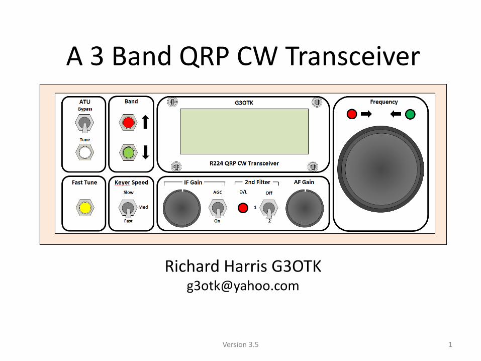

A 3 Band QRP CW Transceiver 3 Band QRP CW Transceiver ... Transmitter Section ... 106 stations in 4...
36
Transcript of A 3 Band QRP CW Transceiver 3 Band QRP CW Transceiver ... Transmitter Section ... 106 stations in 4...
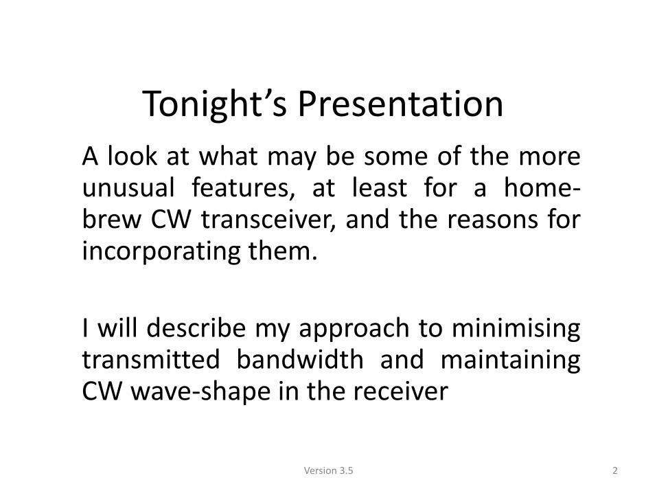
Tonight’s Presentation A look at what may be some of the more unusual features, at least for a home-brew CW transceiver, and the reasons for incorporating them.
I will describe my approach to minimising transmitted bandwidth and maintaining CW wave-shape in the receiver
2 Version 3.5
Headline Features
• 80m, 40m, and 20m CW Transceiver
• 3W RF output
• Auto-ATU
• Electronic keyer
• Integrates with logging program such as N1MM+ or SD
3 Version 3.5
Features - Receive
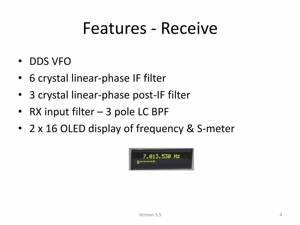
• DDS VFO
• 6 crystal linear-phase IF filter
• 3 crystal linear-phase post-IF filter
• RX input filter – 3 pole LC BPF
• 2 x 16 OLED display of frequency & S-meter
4 Version 3.5
Features - Transmit
• Efficient Class-E PA 3W output
• Output RF waveform rise and fall shaped to minimise transmitted bandwidth
• TX output filtered by same BPF filter as RX input
• Semi-automatic break-in CW operation with sent CW delayed by 0.4 sec
5 Version 3.5
Controlled by 7 PICAXE μPs
• A PICAXE is a PIC with an integral “PICAXE basic” interpreter – easy to program
• Interpreted programs run slower than compiled programs (e.g. Arduino)
• 8 and 16 bit integer arithmetic only
6 Version 3.5
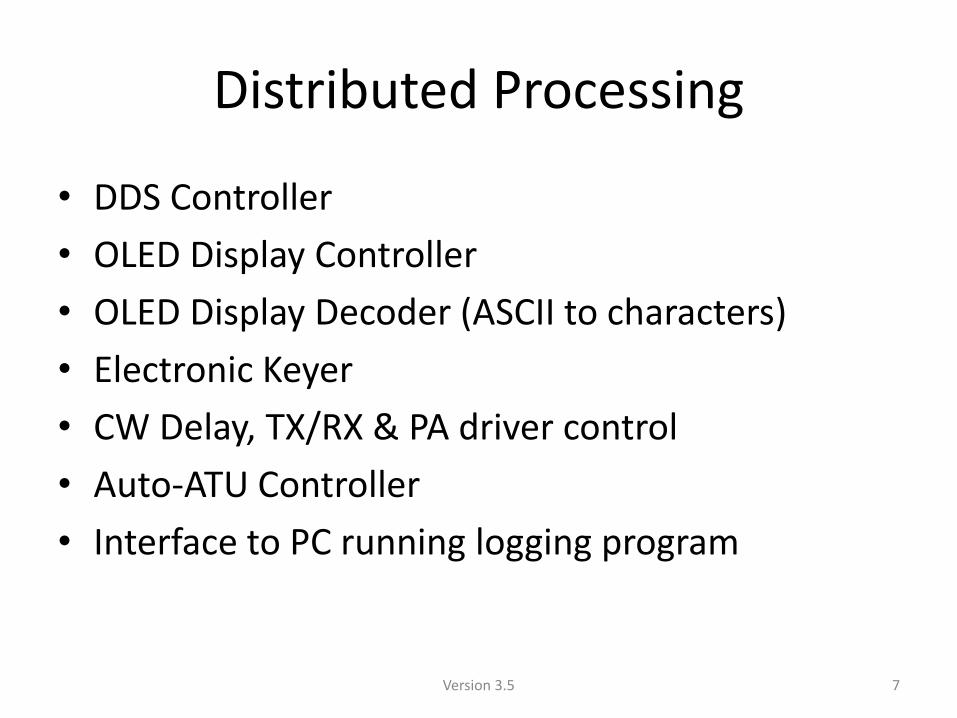
Distributed Processing
• DDS Controller
• OLED Display Controller
• OLED Display Decoder (ASCII to characters)
• Electronic Keyer
• CW Delay, TX/RX & PA driver control
• Auto-ATU Controller
• Interface to PC running logging program
7 Version 3.5
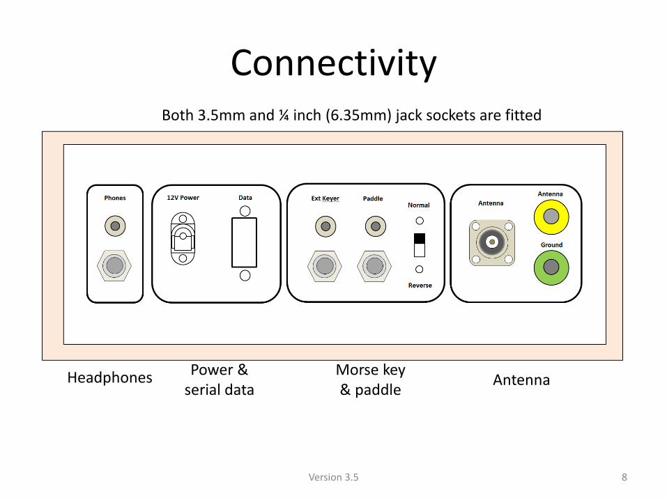
Connectivity
8
Headphones Power & serial data
Morse key & paddle
Antenna
Version 3.5
Both 3.5mm and ¼ inch (6.35mm) jack sockets are fitted
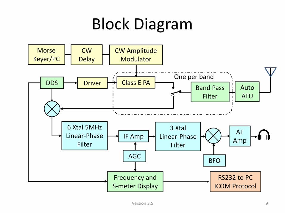
Block Diagram
Band Pass Filter
Class E PA
CW Amplitude Modulator
Driver DDS
6 Xtal 5MHz Linear-Phase
Filter IF Amp
AGC
RS232 to PC ICOM Protocol
AF Amp
CW Delay
Morse Keyer/PC
Frequency and S-meter Display
Auto ATU
One per band
3 Xtal Linear-Phase
Filter
BFO
9 Version 3.5
DDS VFO
10 Version 3.5
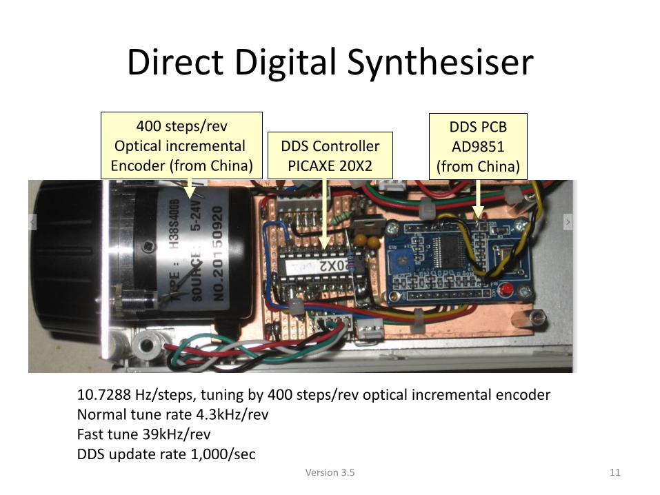
Direct Digital Synthesiser
400 steps/rev Optical incremental
Encoder (from China) DDS Controller PICAXE 20X2
DDS PCB AD9851
(from China)
11
10.7288 Hz/steps, tuning by 400 steps/rev optical incremental encoder Normal tune rate 4.3kHz/rev Fast tune 39kHz/rev DDS update rate 1,000/sec
Version 3.5
Transmitter Section Controlling the Bandwidth
12 Version 3.5
TX Bandwidth - Licence Requirements
• Note (a) of the UK Licence states that:
The bandwidths of emissions should be such as to ensure the most efficient utilisation of the spectrum. In general this requires that bandwidths be kept at the lowest values which technology and the nature of the service permit.
• Excessive bandwidth CW transmissions are heard as “key-clicks” on adjacent frequencies
13 Version 3.5
Bandwidth and CW Readability
• Bandwidth of transmitted signal – The faster the rise and fall times of dots/dashes the
wider the bandwidth
– Sudden changes in the slope of the rise and fall times broadens the transmitted signal
• CW Readability - ARRL Recommendation – Non-fading circuit: 30 wpm, rise & fall times 10ms
– Fading circuit: 30 wpm, rise & fall times 5ms
(For detailed analysis see “Key-clicks and CW Waveform Shaping” on IVARC web site)
14 Version 3.5
CW Signal Bandwidth
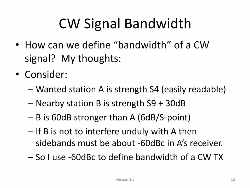
• How can we define “bandwidth” of a CW signal? My thoughts:
• Consider:
– Wanted station A is strength S4 (easily readable)
– Nearby station B is strength S9 + 30dB
– B is 60dB stronger than A (6dB/S-point)
– If B is not to interfere unduly with A then sidebands must be about -60dBc in A’s receiver.
– So I use -60dBc to define bandwidth of a CW TX
15 Version 3.5
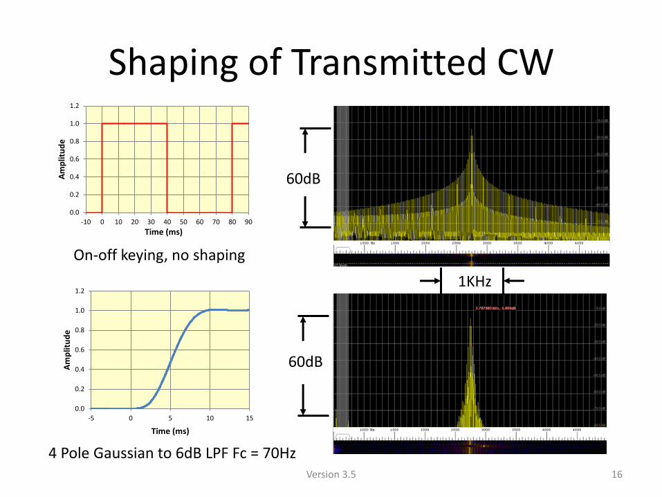
Shaping of Transmitted CW
60dB
1KHz
0.0
0.2
0.4
0.6
0.8
1.0
1.2
-10 0 10 20 30 40 50 60 70 80 90
Am
plit
ud
e
Time (ms)
0.0
0.2
0.4
0.6
0.8
1.0
1.2
-5 0 5 10 15
Am
plit
ud
e
Time (ms)
4 Pole Gaussian to 6dB LPF Fc = 70Hz
On-off keying, no shaping
16
60dB
Version 3.5
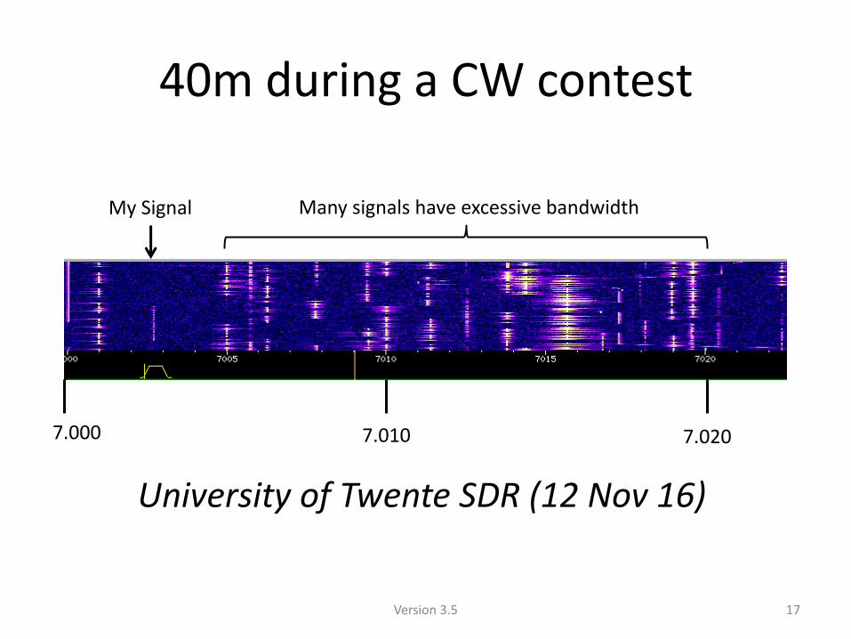
40m during a CW contest
My Signal
7.000 7.010 7.020
University of Twente SDR (12 Nov 16)
Many signals have excessive bandwidth
17 Version 3.5
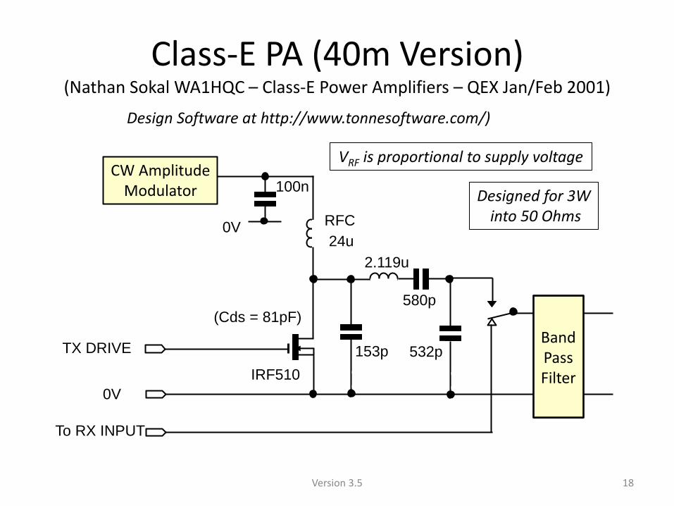
Class-E PA (40m Version) (Nathan Sokal WA1HQC – Class-E Power Amplifiers – QEX Jan/Feb 2001)
18
100n
IRF510
0V RFC
24u
C
C
V
C
C
V
0V
TX DRIVE
2.119u
(Cds = 81pF)
532p
580p
153p
CW Amplitude Modulator
Band PassFilter
Design Software at http://www.tonnesoftware.com/)
To RX INPUT
Designed for 3W into 50 Ohms
VRF is proportional to supply voltage
Version 3.5
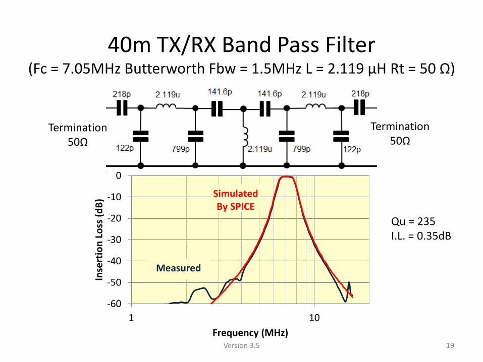
40m TX/RX Band Pass Filter (Fc = 7.05MHz Butterworth Fbw = 1.5MHz L = 2.119 μH Rt = 50 Ω)
-60
-50
-40
-30
-20
-10
0
1 10
Inse
rtio
n L
oss
(d
B)
Frequency (MHz)
Simulated By SPICE
Measured
Termination 50Ω
Termination 50Ω
19
Qu = 235 I.L. = 0.35dB
Version 3.5
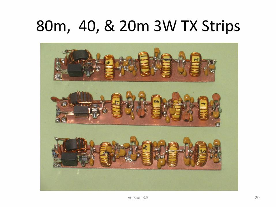
80m, 40, & 20m 3W TX Strips
20 Version 3.5
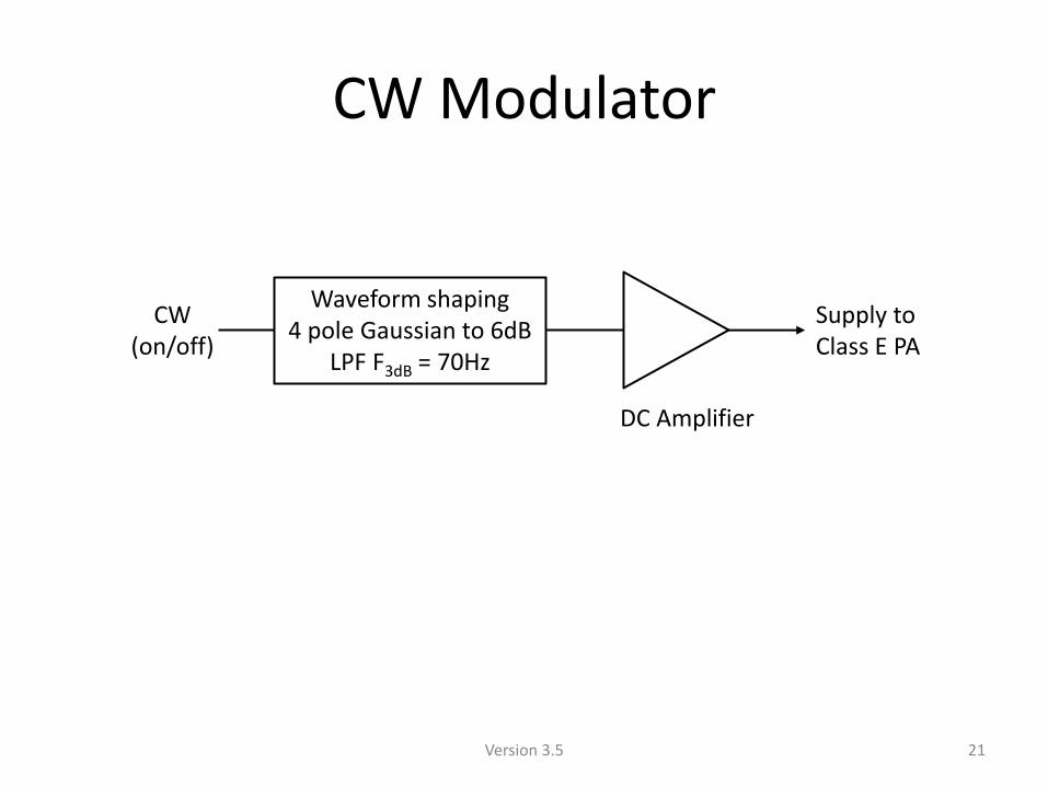
CW Modulator
21
Waveform shaping 4 pole Gaussian to 6dB
LPF F3dB = 70Hz
Supply to Class E PA
CW (on/off)
DC Amplifier
Version 3.5
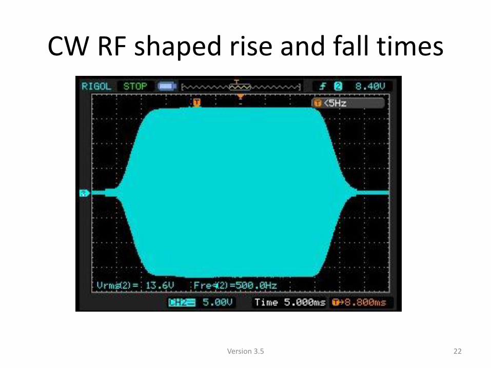
CW RF shaped rise and fall times
22 Version 3.5
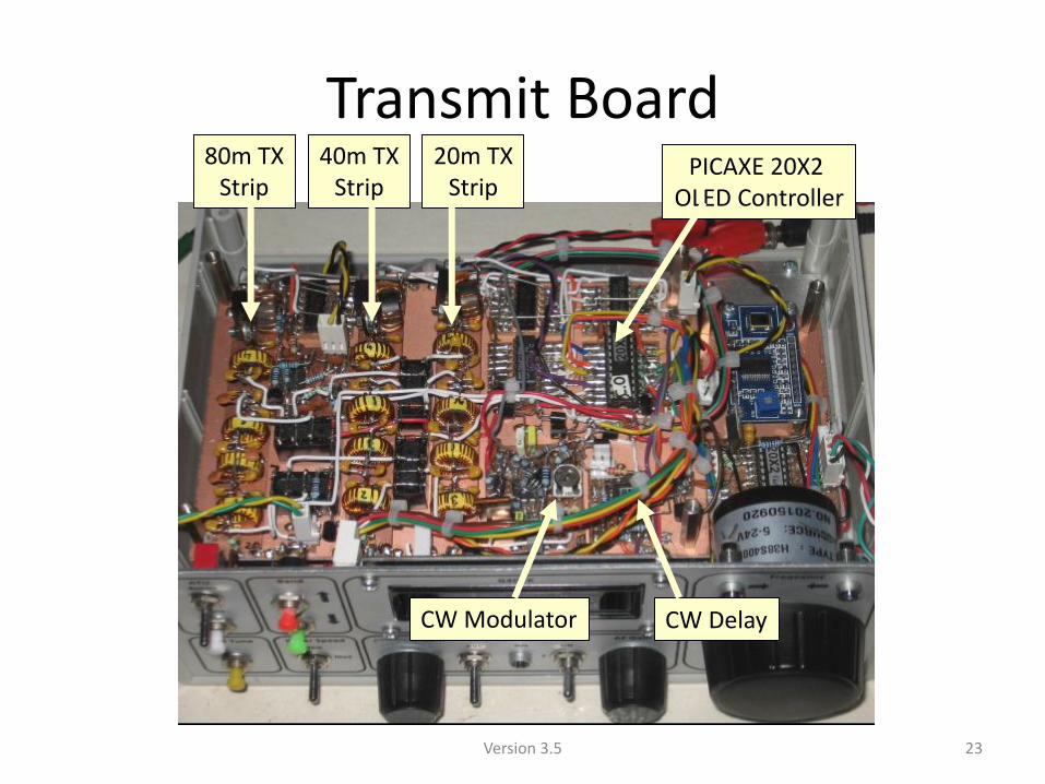
Transmit Board
CW Modulator CW Delay
PICAXE 20X2 OLED Controller
80m TX Strip
40m TX Strip
20m TX Strip
23 Version 3.5
Receiver Section CW Waveform Preservation
24 Version 3.5
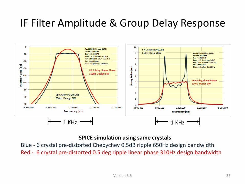
IF Filter Amplitude & Group Delay Response
SPICE simulation using same crystals Blue - 6 crystal pre-distorted Chebychev 0.5dB ripple 650Hz design bandwidth Red - 6 crystal pre-distorted 0.5 deg ripple linear phase 310Hz design bandwidth
1 KHz 1 KHz
25 Version 3.5
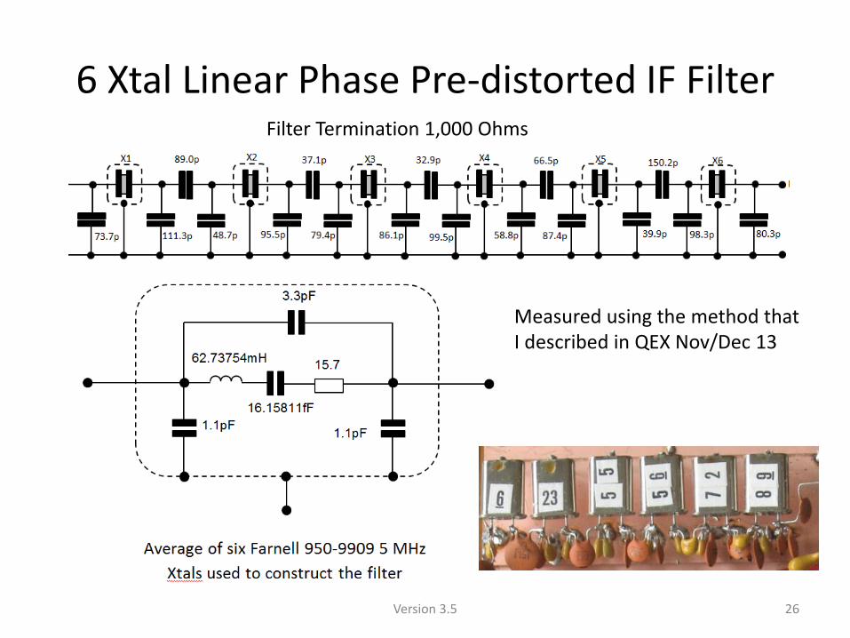
6 Xtal Linear Phase Pre-distorted IF Filter
26
Measured using the method that I described in QEX Nov/Dec 13
Filter Termination 1,000 Ohms
Version 3.5
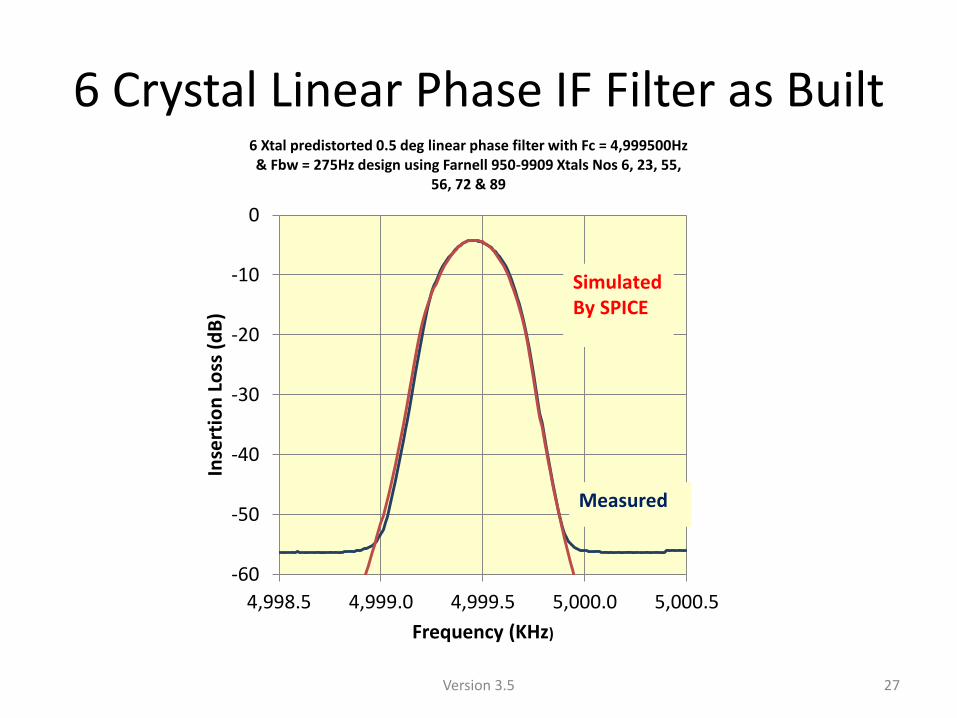
6 Crystal Linear Phase IF Filter as Built
-60
-50
-40
-30
-20
-10
0
4,998.5 4,999.0 4,999.5 5,000.0 5,000.5
Inse
rtio
n L
oss
(d
B)
Frequency (KHz)
6 Xtal predistorted 0.5 deg linear phase filter with Fc = 4,999500Hz & Fbw = 275Hz design using Farnell 950-9909 Xtals Nos 6, 23, 55,
56, 72 & 89
Measured
Simulated By SPICE
27 Version 3.5
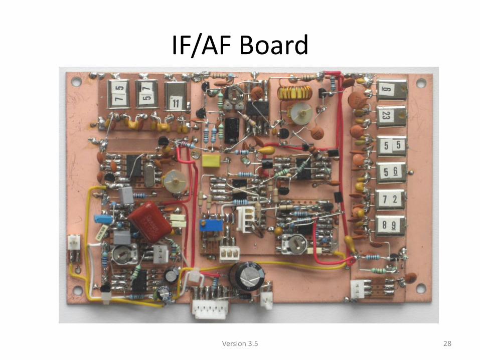
IF/AF Board
28 Version 3.5
TX/RX Changeover
29 Version 3.5
TX/RX Changeover
• Semi-automatic break-in used (similar to VOX)
– Goes to transmit as soon as Morse is key pressed
– Stays on transmit while keying (keying resets a timer)
– 0.4 sec after last dot/dash it then switches to receive
BUT
• The other station may start sending before the receiver is active, so can miss part of call sign
– In 80m Club Contest I read DQ6Q as IQ6Q
– I missed the first dash because still on transmit
30 Version 3.5
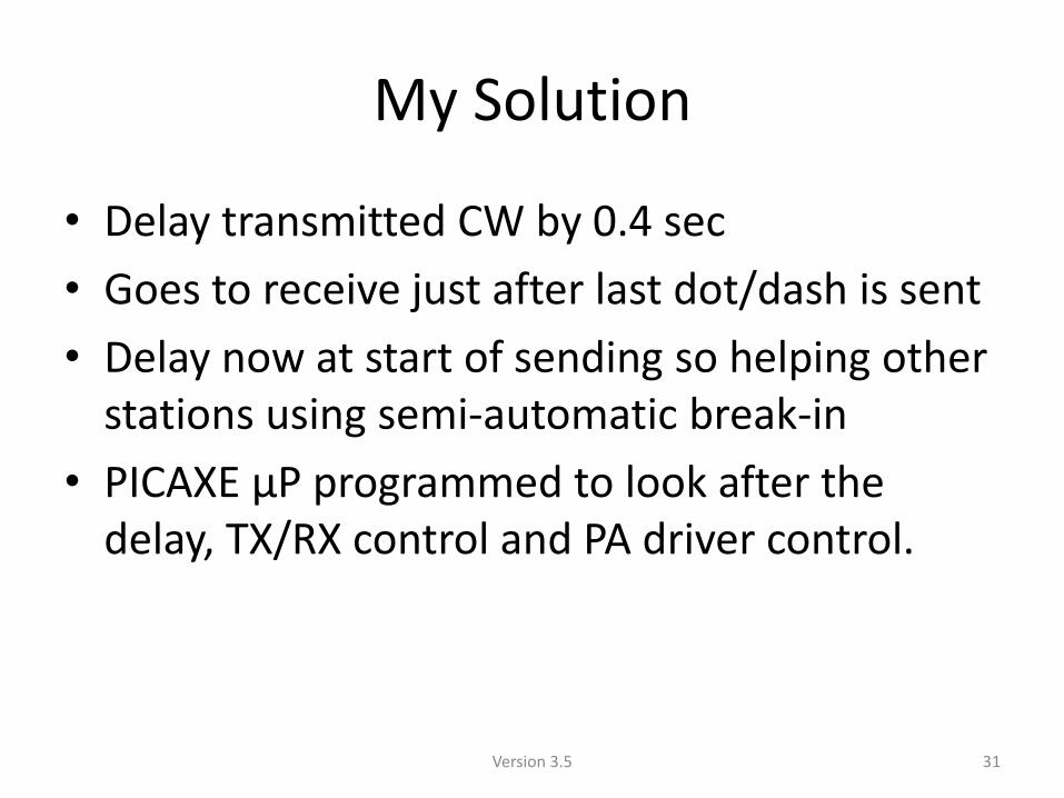
My Solution
• Delay transmitted CW by 0.4 sec
• Goes to receive just after last dot/dash is sent
• Delay now at start of sending so helping other stations using semi-automatic break-in
• PICAXE μP programmed to look after the delay, TX/RX control and PA driver control.
31 Version 3.5
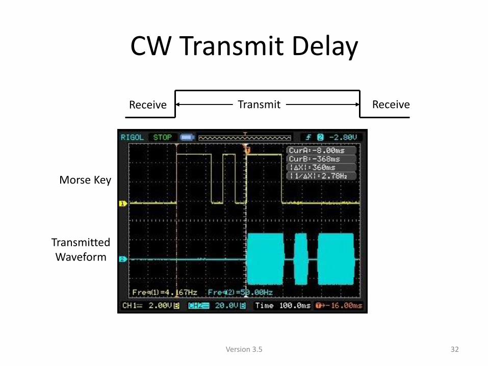
CW Transmit Delay
Transmit Receive Receive
Morse Key
Transmitted Waveform
32 Version 3.5
Auto ATU
33 Version 3.5
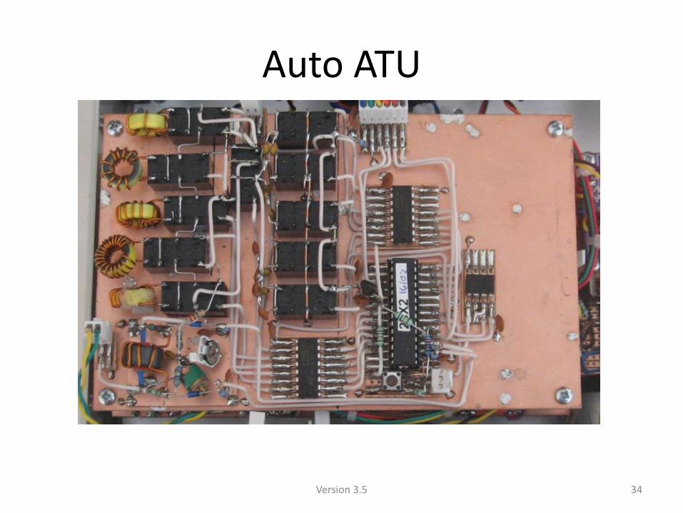
Auto ATU
34 Version 3.5
Some Results with 3W RF Power
• Breadboard versions – Jul 16 – Low Power Contest – 2nd out of 6 entries in
3W Fixed category using 80 & 40m dipoles at 3m
• With completed transceiver: – 8 Jan – AFS Contest – 106 stations in 4 hours on 40m
and 80m using dipoles at 3m height (9th out of 14 entries)
– 19 Feb – Completed transceiver with 8m of wire indoors – worked US stations on 20m in contest
– 23 Feb – 80m CW Club Contest - 61 contacts – best DX SM and OK with dipole at 3m
35 Version 3.5

End
36 Version 3.5