A 1.5-V 6-10-GHz Low LO-Power Broadband CMOS Folded-Mirror Mixer for UWB Radio
15
A 1.5-V 6-10-GHz Low LO-Power Broadband CMOS Folded-Mirror Mixer for UWB Radio H.-W. Chung, H.-C. Kuo, and H.-R. Chuang Institute of Computer and Communication Engineering, Department of Electrical Engineering, National Cheng Kung University, Tainan, Taiwan, R. O. C Presenter : Meng-Long Hsin 1
-
Upload
jacqueline-chapman -
Category
Documents
-
view
32 -
download
0
description
A 1.5-V 6-10-GHz Low LO-Power Broadband CMOS Folded-Mirror Mixer for UWB Radio. H.-W. Chung, H.-C. Kuo, and H.-R. Chuang Institute of Computer and Communication Engineering, Department of Electrical Engineering, National Cheng Kung University, Tainan, Taiwan, R. O. C. - PowerPoint PPT Presentation
Transcript of A 1.5-V 6-10-GHz Low LO-Power Broadband CMOS Folded-Mirror Mixer for UWB Radio
A 1.5-V 6-10-GHz Low LO-Power Broadband CMOS Folded-Mirror Mixer for UWB Radio
H.-W. Chung, H.-C. Kuo, and H.-R. ChuangInstitute of Computer and Communication Engineering, Department of Electrical Engineering,
National Cheng Kung University,Tainan, Taiwan, R. O. C
Presenter : Meng-Long Hsin
1

Abstract• A 6-10 GHz broadband down conversion mixer
for UWB radio is presented.
• The broadband mixer only needs a low LO power of -3 dBm which can reduce the effect of LO leakage and DC offset.
• The broadband mixer exhibits a maximum conversion gain of 0.8 dB, and a DC power consumption of 15.75 mW at =1.5V.DDV
2
Outline
• Introduction
• Circuit Design
• Implementation and Measurement Results
• Conclusion
3

Introduction
• DS-UWB technology can be applied to three frequency band (3.1-5.15 GHz, 5.8-10.6 GHz, and both of them).
• The LO frequency is chosen at 8 GHz and the mixer directly down converts the 6-10 GHz RF signal into the 0-2 GHz IF frequency band.
4
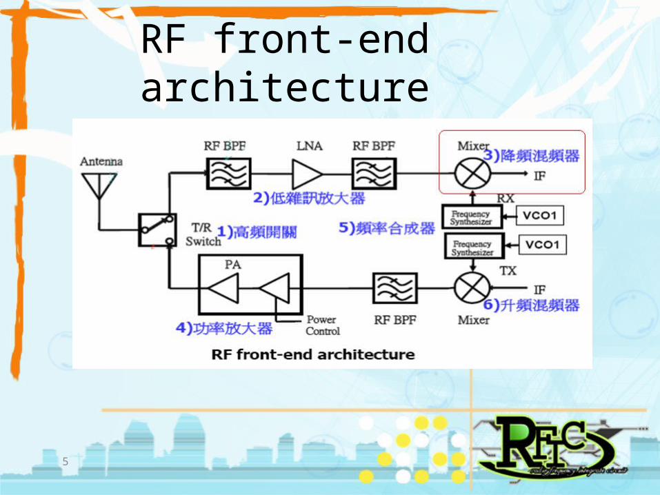
RF front-end architecture
5
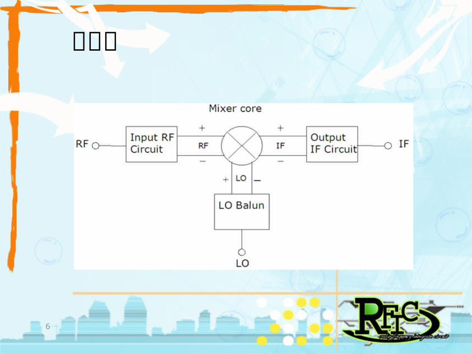
架構圖
6
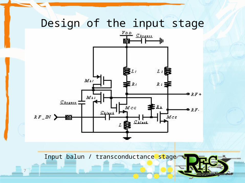
Design of the input stage
Input balun / transconductance stage
7

Consideration on the LO port
LO matching network
8

Design of the switch stage
9
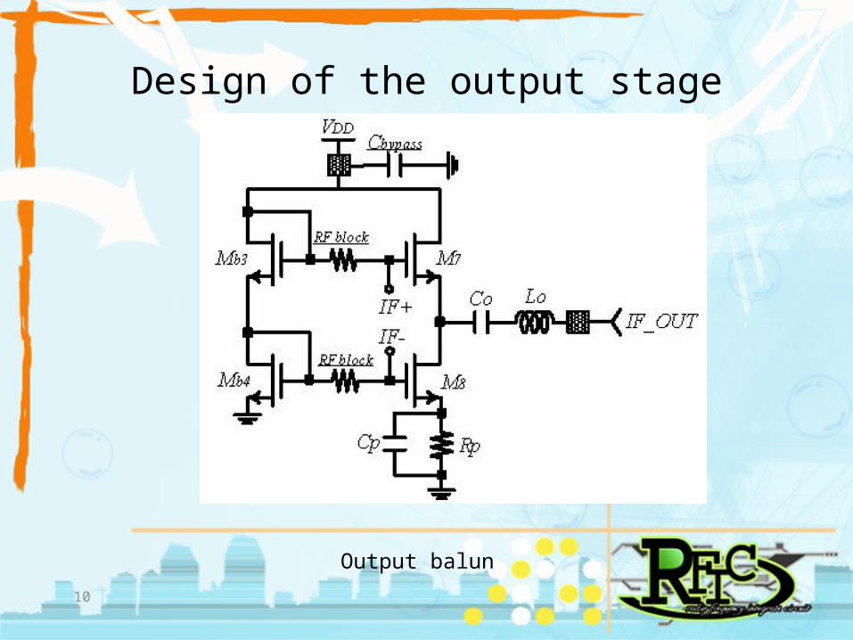
Design of the output stage
Output balun
10

Simulation Results
Measured conversion gain and noise figure
11

Simulation Results(cont.)
Measured input P1dB and IIP3
Measured LO-RF,LO-IF and RF-IF isolation
12

Chip micrograph
13
Conclusion
14
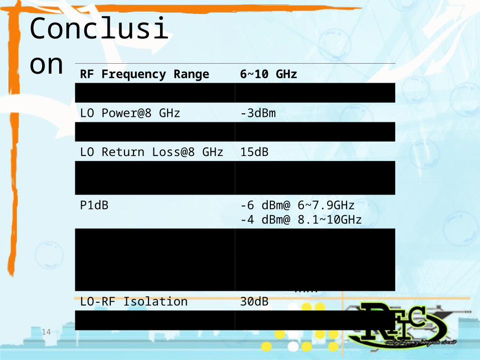
RF Frequency Range 6~10 GHz
IF Frequency Range 100MHz~2GHz
LO Power@8 GHz -3dBm
RF Return Loss >14dB
LO Return Loss@8 GHz 15dB
Conversion -1.8~0.8dB@ 6~7.9GHz-3~-0.4dB@ 8.1~10GHz
P1dB -6 dBm@ 6~7.9GHz-4 dBm@ 8.1~10GHz
IIP3 -1.4~0.4 dBm @ 6~7.9GHz-0.3~-1.8 dBm @ 8.1~10GHz
LO-RF Isolation 30dB
Die Size 1.06×1.112mm

Thanks for your attention.
15


![UWB Radars [EDocFind.com]](https://static.fdocuments.in/doc/165x107/577d2b9c1a28ab4e1eaae39f/uwb-radars-edocfindcom.jpg)