9th Workshop on Knowledge Engineering and Software ...ceur-ws.org/Vol-1070/kese9-procs.pdf ·...
88
9th Workshop on Knowledge Engineering and Software Engineering (KESE) at the 36th German Conference on Artificial Intelligence (KI2013) September 17, 2013, Koblenz, Germany Grzegorz J. Nalepa and Joachim Baumeister (Editors) Technical Report No. 487, W¨ urzburg University, W¨ urzburg, Germany, 2013
Transcript of 9th Workshop on Knowledge Engineering and Software ...ceur-ws.org/Vol-1070/kese9-procs.pdf ·...

9th Workshop on
Knowledge Engineering
and Software Engineering (KESE)
at the
36th German Conference on Artificial Intelligence (KI2013)
September 17, 2013, Koblenz, Germany
Grzegorz J. Nalepa and Joachim Baumeister (Editors)
Technical Report No. 487, Wurzburg University, Wurzburg, Germany, 2013

The KESE Workshop Series is available online: http://kese.ia.agh.edu.pl
Technical Reports of the Wurzburg University: http://www.informatik.uni-wuerzburg.de/forschung/technical reports

Preface
Grzegorz J. Nalepa and Joachim Baumeister
AGH University of Science and Technology
Kraków, Poland
�
denkbares GmbH
Friedrich-Bergius-Ring 15, 97076 Würzburg, Germany
Research questions and practical exchange between Knowledge Engineeringfor intelligent systems and Software Engineering of advanced software programshave been fruitfully discussed over the last years. Many successful examplesdemonstrate the clear symbiosis between these two research areas.
In 2005 the KESE workshops took place for the �rst time in Koblenz at the28th German Conference on Arti�cial Intelligence (KI-2005). Nine years laterthe KESE9 workshops return to Koblenz, where it is collocated with the 36thAnnual Conference on Arti�cial Intelligence in Koblenz (September 16-20, 2013).This year we solicited contributions having the following topics:
� Knowledge and software engineering for the Semantic Web� Ontologies in practical knowledge and software engineering� Business Rules design, management and analysis� Business Processes modeling in KE and SE� Practical knowledge representation and discovery techniques in software en-gineering
� Agent-oriented software engineering� Context and explanation in intelligent systems� Knowledge base management in KE systems� Evaluation and veri�cation of KBS� Practical tools for KBS engineering� Process models in KE applications� Software requirements and design for KBS applications� Declarative, logic-based, including constraint programming approaches in SE
As from the beginning the workshop series shows a healthy mixture of ad-vanced research papers showing the direction to the next years and practical pa-pers demonstrating the actual applicability of approaches in (industrial) projectsand concrete systems. This year �ve regular, and two short papers were acceptedto the workshop. Moreover, one tool presentation was also included.
In their paper "Integrating Semantic Knowledge in Data Stream Processing"the authors Beckstein et al. describe di�erent approaches on integrating streamdata and semantic domain knowledge. In particular, as accessing methods thecontinuous query language CQL is compared with the SPARQL extension C-SPARQL.

Kramer et al. describe new possibilities for explanation generation. Their pa-per "Towards Explanation Generation using Feature Models in Software ProductLines" investigate how the approach can be applied in dynamic software productlines (DSPL).
In the paper "A Prolog Framework for Integrating Business Rules into JavaApplications" the authors Ostermayer and Seipel show an approach to connectthe data structures of the logic-based language Prolog with the wide-spreadprograming language Java.
Baumeister et al. report in their paper "Continuous Knowledge Representa-tions in Episodic and Collaborative Decision Making" on a new type of decisionsupport systems and demonstrate its application in an industrial case study formanaging the knowledge about chemical substances.
Pascalau introduces guidelines for designing and engineering advanced soft-ware systems to be used by end-users. The paper "Identifying Guidelines forDesigning and Engineering Human-Centered Context-Aware Systems" proposesa declarative level to hide the technical level of systems engineering from theend-users.
Kluza et al. tackle business process modeling and give an overview of recom-mendation possibilities. Their paper "Overview of Recommendation Techniquesin Business Process Modeling" describes a categorization of recommendationapproaches.
Newo and Altho� report in their paper "Knowledge Acquisition for LifeCounseling" on a concrete project that uses case-based techniques and infor-mation extraction methods in the life counseling domain.
Kaczor et al. give a tool presentation and show in "HaDEsclipse - IntegratedEnvironment for Rules" an environment for engineering rule-based systems. Thetool is based in the well-established software tool Eclipse.
The organizers would like to thank all who contributed to the success of theworkshop. We thank all authors for submitting papers to the workshop, and wethank the members of the program committee as well as the external reviewersfor reviewing and collaboratively discussing the submissions. For the submissionand reviewing process we used the EasyChair system, for which the organizerswould like to thank Andrei Voronkov, the developer of the system. Last but notleast, we would like to thank the organizers of the KI 2013 conference for hostingthe KESE9 workshop.
Grzegorz J. NalepaJoachim Baumeister

Workshop Organization
The 9th Workshop on Knowledge Engineering and Software Engineering(KESE9)
was held as a one-day event at the36th German Conference on Arti�cial Intelligence
(KI2013)on September 17 2013, in Koblenz, Germany
Workshop Chairs and Organizers
Joachim Baumeister, denkbares GmbH, GermanyGrzegorz J. Nalepa, AGH UST, Kraków, Poland
Programme Committee
Isabel María del Águila, University of Almeria, SpainKlaus-Dieter Altho�, University Hildesheim, GermanyKerstin Bach, Verdande Technology AS, NorwayJoachim Baumeister, denkbares GmbH/University Wuerzburg, GermanyJoaquín Cañadas, University of Almeria, SpainAdrian Giurca, BTU Cottbus, GermanyJason Jung, Yeungnam University, KoreaRainer Knauf, TU Ilmenau, GermanyMirjam Minor, Johann Wolfgang Goethe-Universität Frankfurt, GermanyPascal Molli, University of Nantes - LINA, FranceGrzegorz J. Nalepa, AGH UST, Kraków, PolandJosé Palma, University of Murcia, SpainAlvaro E. Prieto, Univesity of Extremadura, SpainThomas-Roth Berghofer, University of West London, UKJosé del Sagrado, University of Almeria, SpainDietmar Seipel, University Würzburg, Germany

Table of Contents
Integrating Semantic Knowledge in Data Stream Processing . . . . . . . . . . . . 1Simon Beckstein, Ralf Bruns, Juergen Dunkel and Leonard Renners
Towards Explanation Generation using Feature Models in SoftwareProduct Lines . . . . . . . . . . . . . . . . . . . . . . . . . . . . . . . . . . . . . . . . . . . . . . . . . . . . 13
Dean Kramer, Christian Sauer and Thomas Roth-Berghofer
Towards Continuous Knowledge Representations in Episodic andCollaborative Decision Making . . . . . . . . . . . . . . . . . . . . . . . . . . . . . . . . . . . . . . 24
Joachim Baumeister, Albrecht Stri�er, Marc Brandt and Michael Neu-
mann
Identifying Guidelines for Designing and Engineering Human-CenteredContext-Aware Systems . . . . . . . . . . . . . . . . . . . . . . . . . . . . . . . . . . . . . . . . . . . . 36
Emilian Pascalau
Overview of Recommendation Techniques in Business Process Modeling . . 46Krzysztof Kluza, Mateusz Baran, Szymon Bobek and Grzegorz J. Nalepa
A Prolog Framework for Integrating Business Rules into Java Applications 58Ludwig Ostermayer and Dietmar Seipel
Knowledge Acquisition for Life Counseling . . . . . . . . . . . . . . . . . . . . . . . . . . . 70Régis Newo and Klaus-Dieter Altho�
HaDEsclipse - Integrated Environment for Rules (Tool Presentation) . . . . 77Krzysztof Kaczor, Grzegorz J. Nalepa and Krzysztof Kutt

1
Integrating Semantic Knowledge inData Stream Processing
Simon Beckstein, Ralf Bruns, Jurgen Dunkel, Leonard Renners
University of Applied Sciences and Arts Hannover, GermanyEmail: [email protected]
Abstract. Complex Event Processing (CEP) has been established as awell-suited software technology for processing high-frequent data streams.However, intelligent stream based systems must integrate stream datawith semantical background knowledge. In this work, we investigatedifferent approaches on integrating stream data and semantic domainknowledge. In particular, we discuss from a software engineering per-spective two different architectures: an approach adding an ontology ac-cess mechanism to a common Continuous Query Language (CQL) iscompared with C-SPARQL, a streaming extension of the RDF querylanguage SPARQL.
1 Introduction
Nowadays, much information is provided in form of data streams: sensors, soft-ware components and other sources are continuously producing fine-grained datathat can be considered as streams of data. Examples of application fields exploit-ing data streams are traffic management, smart buildings, health monitoring, orfinancial trading. Intelligent decision support systems analyze stream data inreal-time to diagnose the actual state of a system allowing adequate reactionson critical situations.
In recent years, Complex Event Processing (CEP) [10] has been established asa well-suited software technology for dealing with high frequent data streams. InCEP each data item in a stream is considered as an event. CEP uses ContinuousQuery Languages (CQL) to describe patterns in event streams, which definemeaningful situations in the application domain.
However, for understanding the business meaning of stream data, the dataitems must be enriched with semantical background knowledge. For instancein traffic management, velocity measures must be related to specific knowledgeabout the road network (e.g. road topology and speed limits). In contrast todata streams, this background or domain knowledge is usually rather static andstable, i.e. without frequent changes.
Ontologies defined by Description Logic (DL) [8] provide a well-known for-malism for knowledge representation, that can also be used for describing back-ground knowledge. DL distinguishes two different aspects: (1) the TBox con-tains terminological or domain concepts, and (2) the ABox defines assertional
2
knowledge or individuals of the concepts that are defined in the TBox. Com-mon languages for describing semantic knowledge are the Resource DescriptionFramework (RDF) for the TBox and the Ontology Language OWL1 for theABox. SPARQL [11] provides a standard query language for retrieving knowl-edge represented in form of RDF data.
Note that SPARQL was originally developed to process static data and istherefore not suitable for the processing of data streams. Otherwise, conventionalCEP languages provide no inherent concepts for accessing ontological knowledge.
In this work, we will investigate different approaches on how to integratedata stream processing and background knowledge bases. In particular, we willdiscuss two different aspects from a software engineering perspective:
– How can CQL languages provided by standard CEP systems make use ofontology models?
– How useful are recently proposed streaming extensions of SPARQL such asC-SPARQL?
The remainder of the paper is organized as follows. The next section discussesrelated work and other research approaches. Subsequently, section 3 introducesbriefly CEP. Then, section 4 discusses the different types of information that canbe exploited in stream based systems. The following sections 5 and 6 describeand compare two different approaches of integrating background knowledge intostream processing: The first approach adds an ontology access mechanism to acommon CQL-based architecture. The second one uses C-SPARQL, a streamingextension of SPARQL. The final section 7 provides some concluding remarks andproposes an outlook for further lines on research.
2 Related Work
In practice, nearly all stream processing systems are using a proprietary Con-tinuous Query Language (CQL). At present, many mature implementations ofevent processing engines already exist. Some well-known representatives are ES-PER2, JBoss Drools Fusion3 or Oracle CEP4. As already discussed, none ofthese engines neither target nor support a built-in way to integrate semanticbackground knowledge.
Another class of approaches target the integration of RDF ontologies withstream processing. Different SPARQL enhancements have been developed inorder to query continuous RDF streams. Basically, they all extend SPARQL bysliding windows for RDF stream processing:
– C-SPARQL provides an execution framework using existing data manage-ment systems and triple stores. Rules distinguish a dynamic and a static part,which are evaluated by a CQL and a SPARQL engine, respectively [5, 4].
1 http://www.w3.org/TR/2012/REC-owl2-primer-20121211/2 http://esper.codehaus.org/3 http://jboss.org/drools/drools-fusion.html4 http://oracle.com/technetwork/middleware/complex-event-processing

3
– Streaming-SPARQL simply extends a SPARQL engine to support windowoperators [6].
– EP-SPARQL is used with ETALIS, a Prolog based rule engine. The knowl-edge (in form of RDF) is transformed into logic facts and the rules aretranslated into Prolog rules [1, 2].
– CQELS introduces a so called white-box approach, providing native process-ing of static data and streams by using window operators and a triple-baseddata model [9].
Beside SPARQL extensions, various proprietary CEP languages have beenproposed for integrating stream processing and ontological knowledge: For in-stance, Teymourian et. al. present ideas on integrating background knowledgefor their existing rule language Prova5 (with a corresponding event processingengine) [13, 14].
In summary, many proposals for SPARQL dialects or even new languageshave been published, but so far not many results of practical experiments havebeen proposed.
This paper examines two different approaches for integrating RDF and streamdata from a software engineering perspective. First, we extend the well-knownCQL of ESPER with mechanisms for accessing RDF ontologies. Then, this ap-proach is compared with C-SPARQL, one of the SPARQL extensions that inte-grates SPARQL queries and stream processing.
3 Complex Event Processing - Introduction
Complex Event Processing (CEP) is a software architectural approach for pro-cessing continuous streams of high volumes of events in real-time [10]. Everythingthat happens can be considered as an event. A corresponding event object car-ries general metadata (event ID, timestamp) and event-specific information, e.g.a sensor ID and some measured data. Note that single events have no specialmeaning, but must be correlated with other events to derive some understandingof what is happening in a system. CEP analyses continuous streams of incomingevents in order to identify the presence of complex sequences of events, so calledevent patterns.
A pattern match signifies a meaningful state of the environment and causeseither creating a new complex event or triggering an appropriate action.
Fundamental concepts of CEP are an event processing language (EPL), toexpress event processing rules consisting of event patterns and actions, as well asan event processing engine that continuously analyses event streams and executesthe matching rules. Complex event processing and event-driven systems generallyhave the following basic characteristics:
5 https://prova.ws/

4
– Continuous in-memory processing : CEP is designed to handle a consecutiveinput stream of events and in-memory processing enables real-time opera-tions.
– Correlating Data: It enables the combination of different event types fromheterogenous sources. Event processing rules transform fine-grained simpleevents into complex (business) events that represent a significant meaningfor the application domain.
– Temporal Operators: Within event stream processing, timer functionalities aswell as sliding time windows can be used to define event patterns representingtemporal relationships.
4 Knowledge Base
In most application domains, different kinds of knowledge and information can bedistinguished. In the following, the different types of knowledge are introducedby means of a smart building scenario:6 An energy management system thatuses simple sensors and exploits the background knowledge about the building,environment and sensor placement.
The main concepts used in the knowledge base are rooms and equipment,such as doors and windows of the rooms. Rooms and equipment can be attachedwith certain sensors measuring the temperature, motion in a room or the state ofa door or a window, respectively. By making use of this background information,the raw sensor data can be enriched and interpreted in a meaningful manner. Forinstance, room occupancies due to rescheduled lectures or ad-hoc meetings canbe identified for achieving a situation-aware energy management. In this samplescenario, we can identify three types of knowledge classified according to theirdifferent change frequencies:
1. Static knowledge: We define static knowledge as the knowledge about thestatic characteristics of a domain, that almost never or very infrequentlychanges. A typical example in our scenario is the structure of a building andthe sensor installation.Static knowledge can be modeled by common knowledge representation for-malisms such as ontologies. Because this information does usually not change,appropriate reasoners can derive implicit knowledge before the start of thestream processing. OWL can serve as a suitable knowledge representationlanguage that is supported by various reasoners, for example KAON27 orFaCT++8.
2. Semi-dynamic knowledge: We consider semi-dynamic knowledge as theknowledge about the expected dynamic behavior of a system. It can be rep-resented by static knowledge models, e.g. ontologies, as well. In our scenario,a class schedule predicts the dynamic behavior of the building: though the
6 More details about the smart building scenario can be found in [12].7 http://kaon2.semanticweb.org/8 http://owl.man.ac.uk/factplusplus/
5
class schedule can be defined by static data (e.g facts in an ontology), itcauses dynamic events, e.g. each monday at 8:00 a ’lecture start’ event. Ofcourse, real-time data produced by sensor could outperform the predictedbehavior, e.g. if a reserved class room is not used.
3. High-dynamic knowledge: The third type of knowledge is caused by un-forseeable incidents in the real world. It expresses the current state of thereal world and cannot be represented by a static ontology. Instead the cur-rent state has to be derived from continuous stream of incoming data. Thistype of knowledge can be described by an event model specifying the typesof valid events.9 Examples in our scenario are sensor events representing ob-servations in the physical world, e.g. motion, temperature, or the state of awindow or door, respectively.
The three knowledge types introduced above provide only a basic classifica-tion scheme. As already discussed in the introduction (section 1), various typesof information must be integrated and correlated in order to derive complexevents that provide insight to the current state of a system.
5 Using Semantic Knowledge in Event Processing
In this section, we will investigate how the different types of knowledge intro-duced above can be integrated in stream processing – in particular, how onto-logical knowledge can be exploited in stream processing.
We start our discussion with a small part of an ontology for our energymanagement scenario (see Figure 1). This sample ontology is used in the follow-ing paragraphs for discussing the different knowledge integration approaches.The model defines the three concepts ’room’, ’sensor’ and ’equipment’ and theirrelationships. It shows that each room can contain sensors and equipment. Fur-thermore, it specifies that a certain sensor is either directly located in a certainroom or attached to an equipment located in a room.
Note that the location of a sensor can be inferred from the location of theequipment it is attached to. The dashed line describes this implicit property,which can be expressed as role composition in Description Logic:
isAttacedTo ○ IsEquippedIn ⊑ hasLocation. A DL role composition can beconsidered as a rule: If a sensor is attached to an equipment and the equipmentis equipped in a certain room, then the sensor is assumed to be located in thesame room.
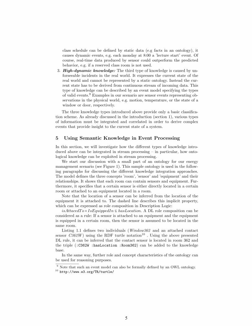
Listing 1.1 defines two individuals (Window362 and an attached contactsensor C362W ) using the RDF turtle notation10 . Using the above presentedDL rule, it can be inferred that the contact sensor is located in room 362 andthe triple (:C362W :hasLocation :Room362) can be added to the knowledgebase.
In the same way, further role and concept characteristics of the ontology canbe used for reasoning purposes.
9 Note that such an event model can also be formally defined by an OWL ontology.10 http://www.w3.org/TR/turtle/

6
Fig. 1. OWL ontology relationship
:Window362
rdf:type :Window ,
:isEquippedIn :Room362 .
:C362W
rdf:type :ContactSensor ,
:isAttachedTo :Window362 .
Listing 1.1. Some sample entries of the domain knowledge
5.1 ESPER
As a first approach of integrating stream data and background knowledge wehave chosen the established event processing engine ESPER. Since it is a regularCQL based engine it does not natively support the access of additional knowledgebases. Figure 2 depicts the conceptional architecture of the approach. Differentevent sources send streams of events via message channels to the ESPER CEPengine. The event sources provide all events in a format that is processableby ESPER, for instance simple Java objects (POJOS). The cycle within theengine should denote that the events are processed in several stages. Each stagetransforms relatively simple incoming events into more complex and meaningfulevents.
Knowledge Access: As already mentioned, ESPER does not inherently sup-port a specific access to a knowledge base such as an OWL ontology, but itprovides a very general extension mechanism that allows invoking static Javamethods within an ESPER rule. Such methods can be used for querying a Javadomain model, a database or any other data source. To make our OWL domain

7
Fig. 2. Architecture using ESPER as CEP component
model accessible from ESPER rules, we implemented an adapter class that usesthe Jena Framework11 to query the ontology via SPARQL.
Events: Because ESPER can only process Java objects, the adapter has to mapRDF triples to Java objects. For instance, the mapping transforms an RDF-URIidentifying a sensor to an ID in the Java object. Each Java class correspondswith a certain concept of the ontology TBox.
Queries: ESPER provides its own event processing language that is called ES-PER Event Query Language (EQL). EQL extends SQL with temporal operatorsand sliding windows. A simple example is given in Listing 1.2 that shows howmotion in a certain room is detected by an ESPER query.
SELECT room
FROM pattern[every mse=MotionSensorEvent],
method:Adapter.getObject(mse.sensorID)
AS room
Listing 1.2. A sample ESPER query
Actions triggered by a pattern match are implemented in a listener class thatmust be registered for an ESPER rule. A listener can call any event handling Javamethod or create a new complex event. The example rule looks rather simple,because the access to the knowledge base is hidden behind the method call(here: Adapter.getObject(mse.sensorID)). In our case, the adapter executesa SPARQL query using the Jena framework as shown in Listing 1.3.
11 http://jena.apache.org

8
PREFIX : <http :// eda.inform.fh-hannover.de/sesame.owl >
PREFIX rdf: <http :// www.w3.org /1999/02⤦
Ç/22-rdf -syntax -ns#>
SELECT ?room ?object
WHERE { :"+sensorID+" :isAttachedTo ?object ;
:hasLocation ?room .
}
Listing 1.3. SPARQL query in the Jena-Adapter method Adapter.getObject(sensorID)
5.2 C-SPARQL
As an alternative approach, we investigate a software architecture using C-SPARQL12, a streaming extension of SPARQL. Figure 3 illustrates the mainbuilding blocks of the architecture. The main difference to the previous approachis, that all event sources produce a continuous stream of RDF data. This meansthat the entire knowledge base of the system uses RDF as uniform descriptionformalism.
Fig. 3. Architecture using C-SPARQL as CEP component
Knowledge access: In this approach, C-SPARQL queries are used for accessingthe homogeneous RDF knowledge base. A single C-SPARQL query can combineincoming RDF streams with static background knowledge (also represented inRDF).
12 We used the ’ReadyToGoPack’, an experimental implementation of the concept in[4, 5], available on http://streamreasoning.org
9
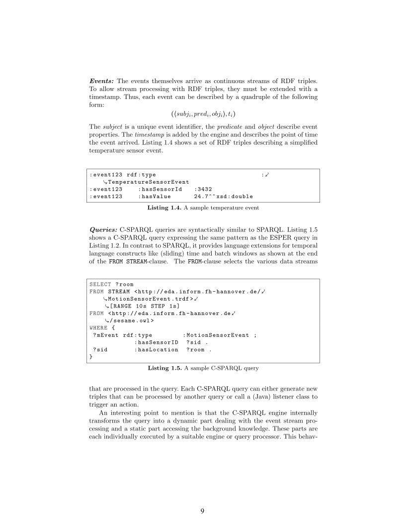
Events: The events themselves arrive as continuous streams of RDF triples.To allow stream processing with RDF triples, they must be extended with atimestamp. Thus, each event can be described by a quadruple of the followingform:
(⟨subji, predi, obji⟩, ti)The subject is a unique event identifier, the predicate and object describe eventproperties. The timestamp is added by the engine and describes the point of timethe event arrived. Listing 1.4 shows a set of RDF triples describing a simplifiedtemperature sensor event.
:event123 rdf:type :⤦
ÇTemperatureSensorEvent
:event123 :hasSensorId :3432
:event123 :hasValue 24.7^^ xsd:double
Listing 1.4. A sample temperature event
Queries: C-SPARQL queries are syntactically similar to SPARQL. Listing 1.5shows a C-SPARQL query expressing the same pattern as the ESPER query inListing 1.2. In contrast to SPARQL, it provides language extensions for temporallanguage constructs like (sliding) time and batch windows as shown at the endof the FROM STREAM-clause. The FROM-clause selects the various data streams
SELECT ?room
FROM STREAM <http :// eda.inform.fh-hannover.de/⤦
ÇMotionSensorEvent.trdf >⤦
Ç[RANGE 10s STEP 1s]
FROM <http :// eda.inform.fh-hannover.de⤦
Ç/sesame.owl >
WHERE {
?mEvent rdf:type :MotionSensorEvent ;
:hasSensorID ?sid .
?sid :hasLocation ?room .
}
Listing 1.5. A sample C-SPARQL query
that are processed in the query. Each C-SPARQL query can either generate newtriples that can be processed by another query or call a (Java) listener class totrigger an action.
An interesting point to mention is that the C-SPARQL engine internallytransforms the query into a dynamic part dealing with the event stream pro-cessing and a static part accessing the background knowledge. These parts areeach individually executed by a suitable engine or query processor. This behav-

10
ior is transparent for the user as the entire rule is written in C-SPARQL and therule result contains the combined execution outcome.
6 Comparison
In this section, we will investigate the capabilities of two introduced approachesof integrating stream processing and background knowledge. Based on our prac-tical experiences, we discuss the two architectures from a software engineeringperspective. Table 1 summarizes the results of the comparison. The criteria willbe discussed in more details in the following paragraphs.
Table 1. Comparison of CQL (ESPER) and C-SPARQL
ESPER C-SPARQLMaturity + –Event Pattern Expressiveness + oConceptual Coherence – +Dynamic Rules o +Heterogeneous knowledge sources o –Stream Reasoning Support – o
Maturity: ESPER is a widely used event processing engine, which is underdevelopment by an active open source community for many years and, conse-quently, has reached a stable and market-ready state. It provides a compre-hensive documentation and several guides, as well as tutorials. In contrast, C-SPARQL, and the ready-to-go-pack in particular, is a conceptual prototype. Thismeans that the implementation is not as mature and, furthermore, it is not asgood documented as ESPER. So far, there are no published experiences aboutreal-world projects using C-SPARQL.
Event Pattern Expressiveness: According to its maturity, ESPER provides arich set of operators for specifying event patterns, e.g. for defining different typesof sliding windows or various even aggregations operators. The event algebra ofC-SPARQL is less expressive compared to ESPER, but, nevertheless, it supportsall important features for general event processing tasks.
Conceptual Coherence: C-SPARQL allows the processing of stream data andthe integration of static background knowledge by using only one paradigm (orlanguage). Listing 1.5 shows a C-SPARQL query that combines event stream pro-cessing and SPARQL queries. In this sense, a C-SPARQL query is self-containedand coherent: only C-SPARQL skills are necessary for understanding it.
In contrast, ESPER does not support inherent access to knowledge bases.Consequently, specialized Java/Jena code must be written to integrate back-ground data. The ESPER-based architecture combines the ESPER query lan-guage (EQL) for stream processing and Jena/SPARQL code implemented in aJava adapter class to query knowledge bases. The ESPER rules are not self-contained and delegate program logic to the adapter classes. Note that this can

11
also be viewed as an advantage: hiding a (perhaps) big part of the logic in methodcalls results in simpler and easier understandable rules.
Dynamic Rules: Changing a rule at runtime is difficult in ESPER, becausemodifying an ESPER rule can cause a change of the EQL pattern and of theSPARQL query in the listener class of the corresponding rule. In this case, thecode must be recompiled. C-SPARQL makes changes much easier, because onlythe C-SPARQL query must be adjusted. Such queries are usually stored asstrings in a separate file, which can be reloaded at runtime - even for rulesincluding completely new queries of the knowledge base.
Heterogeneous knowledge sources: C-SPARQL is limited to ontological back-ground knowledge stored in RDF format. In contrast, ESPER can be extendedby arbitrary adapters allowing the usage of different knowledge sources. For in-stance, beside RDF triple stores also relational databases or NoSQL data sourcescan be used. However, the access methods have to be implemented and main-tained by hand, as mentioned in the previous paragraph.
Stream Reasoning Support: Both approaches do not support stream rea-soning, i.e. implicit knowledge is not automatically deduced when new eventsarrive. Conventional reasoners can only deal with static data, but not with high-frequent RDF streams. But, because (static) background knowledge changesinfrequently, a conventional reasoning step can be processed, if a new fact in thestatic knowledge base appears.
Considering the two approaches from a conceptional point of view, C-SPARQLis better suited for inherent reasoning. For instance, SPARQL with RDFS en-tailment can be achieved by using materialization or query rewriting [7]. Theseapproaches must be extended to stream processing. First discussions about thisissue can be found in [15] and [3].
7 Conclusion
In this paper, we have discussed two different architectural approaches of inte-grating event stream processing and background knowledge.
The first architecture uses a CQL processing engine such as ESPER withan adapter class that performs SPARQL queries on a knowledge base. In thisapproach stream processing and knowledge engineering is conceptually and phys-ically separated.
The second architecture is based on an extension of SPARQL to processRDF data streams. C-SPARQL allows integrated rules that process stream dataand query RDF triple stores containing static background knowledge. Thus,C-SPARQL provides a more homogeneous approach, where query logic, eventpatterns and knowledge base access are combined in one rule and is, therefore,superior from a conceptional point of view.
Otherwise, CQL engines are well-established in real-world projects and at thistime, they offer higher maturity and better performance. Therefore, CQL-basedsystems are (still) superior from a practical point of view.

12
Generally, the integration of semantic reasoning into stream processing is stillan open issue that is not fully supported by any approach yet. Stream reasoningis therefore an important and promising research field to put effort in and hasseveral work in progress, for example the appproaches in [3].
Acknowledgment
This work was supported in part by the European Community (EuropaischerFonds fur regionale Entwicklung) under Research Grant EFRE Nr.W2-80115112.
References
[1] Anicic, D., Fodor, P., Rudolph, S., Stojanovic, N.: Ep-sparql: A unified languagefor event processing and stream reasoning. In: Proceedings of the 20th Interna-tional Conference on World Wide Web. pp. 635–644. ACM (2011)
[2] Anicic, D., Rudolph, S., Fodor, P., Stojanovic, N.: Stream reasoning and complexevent processing in etalis. Semantic Web pp. 397–407 (2012)
[3] Barbieri, D.F., Braga, D., Ceri, S., Della Valle, E., Grossniklaus, M.: Incrementalreasoning on streams and rich background knowledge. ESWC pp. 1–15 (2010)
[4] Barbieri, D.F., Braga, D., Ceri, S., Grossniklaus, M.: An execution environmentfor c-sparql queries. In: Proceedings of the 13th International Conference on Ex-tending Database Technology. pp. 441–452. EDBT (2010)
[5] Barbieri, D.F., Braga, D., Ceri, S., Valle, E.D., Grossniklaus, M.: Querying rdfstreams with c-sparql. SIGMOD Rec. pp. 20–26 (2010)
[6] Bolles, A., Grawunder, M., Jacobi, J.: Streaming sparql - extending sparql toprocess data streams. In: The Semantic Web: Research and Applications, pp.448–462 (2008)
[7] Glimm, B.: Using sparql with rdfs and owl entailment. In: Reasoning Web, pp.137–201. Lecture Notes in Computer Science, Springer Berlin Heidelberg (2011)
[8] Krotzsch, M., Simancik, F., Horrocks, I.: A description logic primer. CoRR (2012)[9] Le-Phuoc, D., Dao-Tran, M., Xavier Parreira, J., Hauswirth, M.: A native and
adaptive approach for unified processing of linked streams and linked data. In:The Semantic Web – ISWC 2011, pp. 370–388 (2011)
[10] Luckham, D.C.: The Power of Events: An Introduction to Complex Event Pro-cessing in Distributed Enterprise Systems. Addison-Wesley (2002)
[11] Prud’hommeaux, E., Seaborne, A.: Sparql query language for rdf,http://www.w3.org/TR/rdf-sparql-query/
[12] Renners, L., Bruns, R., Dunkel, J.: Situation-aware energy control by combiningsimple sensors and complex event processing. In: Workshop on AI Problems andApproaches for Intelligent Environments. pp. 29–34 (2012)
[13] Teymourian, K., Paschke, A.: Enabling knowledge-based complex event process-ing. In: Proceedings of the 2010 EDBT/ICDT Workshops. pp. 37:1–37:7. ACM(2010)
[14] Teymourian, K., Rohde, M., Paschke, A.: Fusion of background knowledge andstreams of events. In: Proceedings of the 6th ACM International Conference onDistributed Event-Based Systems. pp. 302–313. ACM (2012)
[15] Volz, R., Staab, S., Motik, B.: Incrementally maintaining materializations of on-tologies stored in logic databases. In: Journal on Data Semantics II, pp. 1–34.Lecture Notes in Computer Science (2005)

13
Towards Explanation Generation using FeatureModels in Software Product Lines
Dean Kramer, Christian Sauer, and Thomas Roth-Berghofer
School of Computing and Technology, University of West London,St Mary’s Road, London W5 5RF, United Kingdom
{first.lastname}@uwl.ac.uk
Abstract. Dynamic Software Product Line (DSPL) Engineering hasgained interest through its promise of being able to unify software adap-tation whereby software can be configured at compile time and runtime.Just like conventional adaptive software, software dynamism can con-fuse the user, and lower user trust. Variability knowledge expressed in afeature model though may not be understandable to the end user. Expla-nations have been shown to improve intelligibility of the software, andimprove user trust. In this work, we consider how explanations can beused in DSPLs, by adding explanatory knowledge to feature models thatcan be used to generate explanations at runtime.
Keywords: Explanation Generation, Dynamic Software Product Lines,Feature Models
1 Introduction
Smart phones in recent years have seen high proliferation, allowing more usersto stay productive while away from the desktop. It has become common forthese devices to have an array of sensors including GPS, accelerometers, digitalcompass, proximity sensors, sound etc. Using these sensors with other equipmentalready found in phones, a wide set of contextual information can be acquired.
This contextual information can be used in Context-Aware Self Adaptive(CASA) software. This software can monitor different contextual parametersand dynamically adapt at runtime to satisfy the user’s current needs [8]. Thesebehavioural variations can be seen to share similarities with features in SoftwareProduct Lines (SPL), where product commonality and variability is handled,providing higher asset reuse. Within SPLs, Feature Oriented Software Devel-opment (FOSD) has emerged as a method for modularising the features of asystem [3]. The one fundamental difference between these two concepts is thatwhile SPLs conventionally manage static variability which is handled at compiletime, adaptive software requires dynamic variability to be handled at runtime.
Dynamic Software Product Lines (DSPL) enables the SPL to be reconfig-urable at runtime [9]. By using DSPLs, variability can be static, adapted atcompile time, or dynamic and adapted at runtime. This allows for greater reuse

14
as variability can be implemented for both static and dynamic adaptation, as dif-ferent products may require the adaptation to be applied at different times [14].
Feature Modelling has become the de facto method of variability represen-tation, used in software product lines. In feature models, the adaptation of theproduct, be it static, or dynamic, are modelled, enabling a wide variety of prod-ucts and product behaviours. While feature modelling is of great use in thedevelopment, the dynamics within feature modelling can be confusing to end-users. To amend the seemingly unpredictable and thus confusing nature of thebehaviour of a dynamic system and the results it produces, it is desirable toenable the system to explain its behaviour as well as the results it produces tothe end-user. As we will detail further on in this paper explanations are veryuseful to justify results a system produces and thus help to rebuild the trust anend-user has in the systems behaviour and results. So explanations are usefulto the end-user as they can counter the mentioned non-transparency of DSPLend-products and their dynamic behaviours.
In our previous work [18], on enabling a system we developed to gener-ate explanations, we investigated the integration of explanations into a con-text acquisition engine, used for developing context-aware applications. We didthis with regard to mobile applications were one has to adhere to many con-straints. We developed a ContextEngine to easier deal with such limitations andsituation-specific information across applications [12], thus easing the creation ofcontext-aware, mobile systems. We noticed that with the increased adaptabilityand dynamics of context-aware applications came an increase in complexity ofthe application, which in turn made it harder to understand the behaviour ofsuch applications. In our initial research on this topic we then described howwe enhanced the ContextEngine platform with explanation capabilities. As wedescribe in this paper and as it was proven in a variety of other work on ex-planations, explaining can be seen as complex reasoning task on its own. In ourinitial work we focused on the use of canned explanations. Canned explanationsare information artefacts, pre-formulated by the software engineer, that serve asexplanatory artefacts stored in the system and delivered to the user on demand.We integrated storage facilities for such information artefacts, or explanatoryknowledge artefacts within the code structure of the ContextEngine and thuswere able to provide these stored canned explanations on demand to a softwareengineer working with the ContextEngine. After this early steps and relativelysimple approach, based also on a further study into the matter of explanationprovision in the feature model and especially in the automated analysis featuremodels (AAFM) domain, we decided to elaborate on our initial work.
The rest of the paper is structured as follows: We introduce the featuremodelling background of our work in the following section and based on thetechnological possibilities described there motivate our approach to use an ex-tended feature model for explanation generation in Section 3. We then interlinkour approach with related work on feature modelling, explanation generationand the use of explanations itself in the following section. We then introduce ourapproach to explanation generation from explanatory knowledge stored in an

15
extended feature model and demonstrate our concept of explanation generationin Section 5 . After discussing the advantages and possible disadvantages of ourapproach in Section 6 a summary and outlook on future aspects of our workconcludes the paper.
2 Feature Models
The purpose of a feature model is to represent all possible products from a SPLin terms of features, and the relationships between them. An example featuremodel for a content store application is shown in Figure 1. A feature of a system
Fig. 1. Feature Model of a content store
has been described in a number of variations [2]. For this paper, we use thedefinition by Kang et al. [10] in that a feature is “a prominent or distinctiveuser-visible aspect, quality, or characteristic of a software system or systems”.Feature models are modelled using hierarchical trees of features, with each noderepresenting commonality and variability of its parent node. Relationships be-tween each feature can be modelled using:
– Tree feature relationships between parent (compound) features and theirchild features (subfeatures) .
– Cross-tree constraints which typically apply feature inclusion or exclusionstatements, normally using propositional formula. An example of this in-cludes “if ABC is included, then feature XYZ must also be included.”
Within feature models, different feature relationships can be applied includ-ing:
– Mandatory. A child feature is defined as mandatory in all products whereits parent is also contained.

16
– Optional. A child feature is defined as optional when it optionally can beincluded or excluded when its parent is contained in a product.
– Or. A set of child features exhibit an or-relationship when one or morechildren are selected along with the parent of that set.
– Alternative (XOR). A set of child features exhibit an xor-relationshipwhen only a single child can be selected when the parent is included.
Feature models have been applied not only to modelling system features, butalso context [1]. As DSPLs can be driven by context, modelling both contextsand the features that they affect in feature models allows for a single modellinglanguage. The feature models introduced above represent what is known as ba-sic feature models. There have been different additions to feature modelling,including cardinality feature models [7], and extended feature models [6].
Extended feature models extend basic feature models by the ability to attachadditional information about features to the model. This additional informa-tion is included by the use of feature attributes, which are attached to featureswithin the feature model. Feature attributes normally consist of a name, do-main, and value. Feature attributes have been used in previous work for specify-ing extra-functional information [4]. We intend to also use feature attributes inour approach. We will employ additional feature attributes to store explanatoryknowledge artefacts, see section 5.1 for details.
3 Motivation of our work
The GUI of an application, or even more intriguing, the behaviour of an ap-plication generated by the use of SPL can be rather dynamic. This dynamicbehaviour can be confusing if not daunting to the end-user of the application.The end-user might not be aware of why the GUI has adapted and the factorsinfluencing how it changes. Furthermore, the dynamic behaviour of the appli-cation, producing different results while receiving identical inputs just underdifferent circumstances (for example a network being available or not), is a chal-lenge to the trust the user develops towards the applications results. As thefeature model, being the component responsible for the dynamic behaviour ofthe application, is a black box system to the end-user the need for explanationsof this black box systems behaviour arises.
The benefits of being able to explain the behaviour of an application andsubsequently its GUI are plenty. According to [17] there are a number of benefitsexplanations can provide to the end-user. The main benefits of interest withregard to our problem at hand are the generation of trust into the results theapplication generates and justification of and guidance on the changes in theGUI of the application.
As [6] have shown it can be a complicated process to apply abductive reason-ing to generate minimal explanations from the logical representation of a featuremodel within an AAFM. To circumvent the effort involved in using abductivereasoning to generate a minimal explanations from the logical representation ofthe feature model our approach aims at integrating canned ’micro’ or ’atomic’

17
explanations within the logical representation of the feature model. By doing sowe aim to re-use the feature model itself in the same way it is used in the productconfiguration to also ‘configure’ or synthesise more complex explanations of theactual product generated from the ‘atomic’ building blocks given by the canned‘micro’ explanations embedded in the feature descriptions themselves as well asin the representation of the relationships between these features described in thefeature models logical representation.
3.1 Scenario Application
To illustrate our motivation, consider a DSPL example of a content store ap-plication for a mobile device. This application may provide different content forthe user including applications, movies, music etc. Different content is organisedinto different categories. A simplified feature model of the DSPL can be seen inFigure 1. This application provides content for different age groups, and also theapplication can be tailored to suit these different groups.
In the feature model, we can see that the features Payment, ContentTypes,History, and Retrieval are required in every configuration of this DSPL. ThePayment feature handles all payment transactions when content is bought orrented. The ContentTypes feature contains the different components for brows-ing, and buying different types of content. Because different regions in the worldmay require different content distribution licenses, it may not be possible tosell content in every region, so depending on the location of the user, differentcontent type features including Video, Music, and Applications will be boundor unbound. In the History feature, all bought content is found, which can beretrieved in Retrieval. There are two primary methods in which content canbe retrieved, downloaded or streamed. Certain content including video maybedownloaded or streamed. Depending on how much storage is available on thedevice, it may be not be possible to download the movie, so only the Streamingfeature is bound. In Figure 2, we can see the variability of the screen accordingto content type features. If you consider the video feature, there is a button thattakes the user to a set of screens for video content, and also a containership ofwidgets for advertising popular movies.
4 Related Work
Explanations and feature models have been used before, but more to aid the anal-ysis process and error analysis of feature models [20] as well as in automatedfeature model analysis in general as Benavides et al. describe in [5]. As we al-ready mentioned there are a number of goals that can be reached by providingexplanations to the user of a, then, explanation aware system. An explanationaware system is a system that is able to provide explanations of the results itproduces as well as of the means it employs to produce these results [11,13].
The goals pursued by enabling a system to provide explanations [19] are thefollowing: Increase the transparency of a systems reasoning process to increase

18
Fig. 2. Variability of the main screen
the users trust into the system. Justifying results the system produces. This goalaims at explaining the quality and applicability of results the system producedto the end-user. Another goal of explanation provision is to provide relevanceexplanations of either question asked by the system or on information providedby the system. Conceptualisation, thus explanations of the concepts the systemis working on, directly aids the last goal of providing explanations, learning.By explaining the concepts the system works on to the end-user the end-user isenabled to learn about the domain in which the system works.
Our approach to providing applications needs, next to the knowledge usedby the feature model system, additional explanatory knowledge to create the ex-planations we want the system to be able to provide to the end-user. It is alwaysnecessary to provide explanatory knowledge in any system that is intended toprovide explanations on its reasoning [16]. This additional explanatory knowl-edge is provided to and used by the explainer component of an explanation awaresystem, enabling it to provide explanations of its reasoning and results. The needfor additional explanatory knowledge is also shown in [20] as the abduction pro-cess described there is relying also on additional explanatory knowledge.
In our approach the explanatory knowledge needed to generate explanationsin our system will be broken down into ‘atomic’ canned explanatory knowledgeartefacts that will be paired with each feature of the feature model as well as ad-ditional ‘atomic’ canned explanatory knowledge artefacts that will be attachedto the relationship descriptors within our feature model. The aim of this ‘en-richment’ or ‘dotation’ of the feature model with ‘micro’ or ‘atomic’ explanatory

19
knowledge artefacts is it to reuse the artefacts ‘bound’ to the features and theirrelationship descriptors in the final product to synthesise complex explanationsbased on the available ‘bound’ atomic explanatory knowledge artefacts. We fo-cus our approach especially on the issue of explaining a dynamic GUI to theend-user. As for example [15] described in their work the problems that can re-sult from a dynamic and automatically assembled GUI, we aim to amend theseproblems by providing the end-user of an application with an insight into theGUI’s changes by explaining them to her.
5 Our Approach
In our approach, we attempt to enable explanations in DSPLs. By adding ex-planations to DSPLs, we see two benefits. Firstly, explanations have been shownin other work to improve user understanding of a system which can be ap-plied to DSPL systems [13]. Secondly, because a SPL enables many products tobe produced using reusable common assets, we can then easily produce manyexplanation-ware applications, because we can leverage the reuse properties ofthe SPL with the explanations. The first part of our approach regards the mod-elling of the system.
5.1 Modelling
Just as the rest of the system is modelled using feature models, so too are theexplanations. To add explanations to the feature model, we use extended featuremodels. As introduced earlier in the paper, with extended feature models, extraexplanatory information can be attached to features using feature attributes.These feature attributes can be used for storing the specific explanation snippetsfor each feature. For each feature attribute there is a name, domain, and value.The domain of the attribute holds what type of explanation it is, with the valueholding the explanation fragment.
Mapping explanatory knowledge fragments to features is not just enough; wealso need to map explanatory knowledge fragments to feature model relation-ships. Examples of explanatory knowledge fragments mapped to relationshipsinclude:
– Mandatory - “in all configurations”.– Optional - “which is optional”.– Or - “which can be”.– Alternative - “which is either”.
5.2 Composing Explanations
Once we have the explanations added to the feature model, we can compose com-plex explanations. These complex explanations are made up of the concatenationof explanations added to the features and the relationship explanations.

20
Fig. 3. Composing Explanation of why streaming is active
Lets take the example of considering a configuration where content is streamedto the user instead of downloaded as shown in Figure 3. If the user wanted toknow why streaming is active, to generate an explanation we firstly follow thetree from the streaming feature to the root. We then get the conceptual expla-nation of the root, in this case “The content store”. Next we add the conceptualexplanation for the “History” feature, in this case “Stores historical content pur-chases”, and because it is a mandatory feature, we add “in all configurations”.Following this, we add the conceptual explanation for the “Retrieval” feature, inthis case “of which can be retrieved”, and add “in all configurations” because thefeature is mandatory. Then because the sub features of “Retrieval” are alterna-tives, we add “either”, and the two conceptual explanations joined with an “or”.Lastly, because in the configuration, the “Stream” feature is active, we add “inthis case, streamed”. We therefore can ‘reuse’ the structural information encodedin the feature model representation directly for the composition of complex ex-planations by simply ‘re-tracing’ the explanatory knowledge artefacts, stored infeature and relationship nodes, along a path in the feature model.
6 Discussion
The implementation effort is expected to be minor, given the fact that our ap-proach just adds three additional feature attributes to the feature and relation-ship descriptions. The intention of ‘piggyback’ riding the inherent logical struc-ture encoded in the feature model graph to also derive complex explanationsfrom it is still open to be tested for its actual quality of generated explanationsas well as for its scalability. With regard to the scalability of our approach weintend it to be limited. Once a feature model exceeds a certain complexity the

21
coherent concatenation of explanatory knowledge artefacts described in the fea-ture and relation nodes along a path in such a model will fail or become too muchof a computational effort. However we assume that for small to medium scalefeature models our relatively ‘practical’ approach of concatenating explanatoryknowledge artefacts stored in the models nodes is relatively efficient comparedto existing more complex approaches of explanation generation explained, forexample, in [6].
7 Summary and Outlook
In this paper we presented how the variability of SPL based products and theirbehaviours could be explained to their end-users using explanations composedfrom explanatory knowledge added to enhanced feature model nodes. Based onthe feature modelling background of our work we motivated our approach to usean extended feature model for swift explanation generation. We reviewed andcompared our approach with related work on feature modelling, explanationgeneration and the use of explanations itself, especially inspecting approachesemploying relatively complex abductive reasoning. We then introduced our ap-proach to explanation generation from explanatory knowledge stored in extendedfeature model nodes explaining features themselves and their relationships. Bytracing an example graph in a feature model we showed the working of our ap-proach. Given the fact that we are in the early stage of further examining ourapproach we then discussed its possible limitations but also its possible advan-tages given by the fact that our approach promises to be easily implementedbase on existing work on enhanced feature models and is very easy to use forexplanation composition in small to medium sized feature models, compared tomore complex approaches like abductive reasoning.
As we cannot yet predict the effectiveness of our seemingly ‘pragmatic’ ap-proach, we have to implement the enhanced node generation in our existingenhanced feature model and then perform a series of experiments on this en-hanced feature model. The aim of these experiments will be to establish ourapproaches boundaries with regard to parameters such as quality and usabilityof generated explanations as well as the scalability of our approach. We alsohave to measure the computational effort necessary for explanation compositionand then measure it against the gain in usability to establish the worthiness offurther researching our approach of reusing extended feature model structuresfor explanation generation from explanatory knowledge artefacts stored in thenodes of the feature model.
An additional feature of the reuse of an enhanced feature models structurefor explanation generation not yet investigated further is the reuse of proposi-tional logic formulae derived from the feature model. We plan to investigate thepossibilities of this reuse in our immediate follow up research.

22
References
1. Acher, M., Collet, P., Fleurey, F., Lahire, P., Moisan, S., Rigault, J.P.: ModelingContext and Dynamic Adaptations with Feature Models. In: 4th InternationalWorkshop [email protected] at Models 2009 (MRT’09). p. 10 (Oct 2009)
2. Apel, S., Kastner, C.: An overview of feature-oriented software development. Jour-nal of Object Technology 8(5), 49–84 (2009)
3. Batory, D., Sarvela, J., Rauschmayer, A.: Scaling step-wise refinement. IEEETrans. Softw. Eng. 30, 355–371 (June 2004)
4. Benavides, D., Segura, S., Ruiz-Cortes, A.: Automated analysis of feature models20 years later: A literature review. Inf. Syst. 35(6), 615–636 (Sep 2010)
5. Benavides, D., Segura, S., Ruiz-Cortes, A.: Automated analysis of feature models20 years later: A literature review. Information Systems 35(6), 615–636 (2010)
6. Benavides, D., Trinidad, P., Ruiz-Cortes, A.: Automated reasoning on feature mod-els. In: Proceedings of the 17th international conference on Advanced InformationSystems Engineering. pp. 491–503. CAiSE’05, Springer-Verlag, Berlin, Heidelberg(2005)
7. Czarnecki, K., Helsen, S., Ulrich, E.: Formalizing cardinality-based feature modelsand their specialization. Software Process: Improvement and Practice 10, 7 – 29(01/2005 2005)
8. Daniele, L.M., Silva, E., Pires, L.F., Sinderen, M.: A soa-based platform-specificframework for context-aware mobile applications. In: Aalst, W., Mylopoulos, J.,Rosemann, M., Shaw, M.J., Szyperski, C., Poler, R., Sinderen, M., Sanchis, R.(eds.) Enterprise Interoperability, Lecture Notes in Business Information Process-ing, vol. 38, pp. 25–37. Springer Berlin Heidelberg (2009)
9. Hallsteinsen, S., Hinchey, M., Park, S., Schmid, K.: Dynamic software productlines. Computer 41, 93–95 (April 2008)
10. Kang, K., Cohen, S., Hess, J., Nowak, W., Peterson, S.: Feature-Oriented DomainAnalysis (FODA) Feasibility Study. Technical Report CMU/SEI-90-TR-21 (1990)
11. Kofod-Petersen, A., Cassens, J.: Explanations and context in ambient intelligentsystems. In: Modeling and Using Context, pp. 303–316. Springer (2007)
12. Kramer, D., Kocurova, A., Oussena, S., Clark, T., Komisarczuk, P.: An extensi-ble, self contained, layered approach to context acquisition. In: Proceedings of theThird International Workshop on Middleware for Pervasive Mobile and Embed-ded Computing. pp. 6:1–6:7. M-MPAC ’11, ACM, New York, NY, USA (2011),http://doi.acm.org/10.1145/2090316.2090322
13. Lim, B.Y., Dey, A.K., Avrahami, D.: Why and why not explanations improve theintelligibility of context-aware intelligent systems. In: Proceedings of the SIGCHIConference on Human Factors in Computing Systems. pp. 2119–2128. ACM (2009)
14. Parra, C.: Towards Dynamic Software Product Lines: Unifying Design and RuntimeAdaptations. Ph.D. thesis, INRIA Lille Nord Europe Laboratory (March 2011)
15. Pleuss, A., Hauptmann, B., Dhungana, D., Botterweck, G.: User interface engi-neering for software product lines: the dilemma between automation and usability.In: Proceedings of the 4th ACM SIGCHI symposium on Engineering interactivecomputing systems. pp. 25–34. ACM (2012)
16. Roth-Berghofer, T.R.: Explanations and case-based reasoning: Foundational issues.In: Funk, P., Calero, P.A.G. (eds.) Advances in Case-Based Reasoning. pp. 389–403. Springer-Verlag, Berlin, Heidelberg, Paris (September 2004)
17. Roth-Berghofer, T.R., Cassens, J.: Mapping goals and kinds of explanations to theknowledge containers of case-based reasoning systems. In: Case-Based ReasoningResearch and Development, pp. 451–464. Springer (2005)

23
18. Sauer, C., Kocurova, A., Kramer, D., Roth-Berghofer, T.: Using canned explana-tions within a mobile context engine. Explanation-aware Computing ExaCt 2012p. 26 (2012)
19. Sørmo, F., Cassens, J., Aamodt, A.: Explanation in case-based reasoning–perspectives and goals. Artificial Intelligence Review 24(2), 109–143 (2005)
20. Trinidad, P., Benavides, D., Duran, A., Ruiz-Cortes, A., Toro, M.: Automated erroranalysis for the agilization of feature modeling. J. Syst. Softw. 81(6), 883–896 (Jun2008)

24
Towards Continuous Knowledge Representationsin Episodic and Collaborative Decision Making
Joachim Baumeister1, Albrecht Striffler1, Marc Brandt2 and Michael Neumann2
1 denkbares GmbH, Friedrich-Bergius-Ring 15, 97076 Würzburg, Germany{firstname.lastname}@denkbares.com
2 The Federal Environment Agency (Umweltbundesamt), Section IV 2.3 ChemicalsWörlitzer Platz 1, 06844 Dessau-Roßlau, Germany
Abstract. With the success of knowledge-based approaches in decision supportsystems new requirements arise in practice. That way, users demand not only forthe collaborative development of such systems, but also for the collaborative andepisodic use in decision processes. Moreover, in complex decision domains mul-tiple knowledge representations are available that need to be jointly processed. Inthis paper we introduce a novel approach and a system implementation that aimsto meet these requirements.
1 Introduction
In the past, decision support systems based on knowledge bases emphasized the explicitrepresentation of decision knowledge for its automated application in the target sce-nario. Typically, those systems are used monolithically by one user or automated by amachine. Examples are for instance the medical consultation system SonoConsult [12],the medical therapeutic system SmartCare [6], and TIGER [8] for the monitoring of gasturbines. With the success of those systems new requirements arise to adapt into newenvironments. Advanced requirements are as follows:
– Collaborative use: More than one person is working on the same decision processat the same time.
– Episodic use: The actual decision process is not a one-step question-answer inter-view, but needs (sometimes sporadically) input over time, i.e., a decision episode.
– Mixed representation: Systems are build from knowledge bases that do not use asingle knowledge representation (e.g., rules) but a combination, for instance ruleswith models and ontologies.
The requirements stated above call for extensions of todays systems in the followingmanner:
– A systematic extension of systems that support the collaborative and the episodicdecision making. Here, especially an approach of representing the provenance ofdecisions is required.

25
– A continuous knowledge representation to support heterogenous representations fordecision making and its episodic application. Here, the already introduced knowl-edge formalization continuum [2] needs to be reconsidered in the light of its use indecision making.
In this paper, we try to shed more light into fulfilling the requirements mentionedabove. The formalization and use of the knowledge formalization continuum is intro-duced in Section 2. In Section 3 we discuss a systematic approach for episodic decisionmaking in collaborative use. A case study in Section 4 exemplifies the successful appli-cation of the described approach. The overall ideas are summarized and concluded inSection 5.
2 Continuous Knowledge Representation and Application
One main challenge in complex decision making is finding the appropriate scope of theknowledge base: Complex domains require a large number of aspects to be considered.Thus, a ‘complete’ knowledge base needs to include many aspects, to be later useful inpractice. Most of the times however, not all aspects can be included in the knowledgebase:
– Uncertain domain knowledge: Parts of the domain are not well-understood in atechnical sense. Here, decisions in practice are often based more on past experience,evidence, and intuition than on strict domain laws and rules.
– Bloated domain knowledge: For some parts of the domain, the explicit represen-tation of the knowledge would be too time-consuming and complex. For instance,much background knowledge needs to be included, that is required for proper deci-sion making. Here, the expected cost-benefit ratio is low, e.g., because many partswill be rarely used in real-world decisions1.
– Restless domain knowledge: Especially in technical domains, some parts of the do-main knowledge are frequently changing due to technological changes. The explicitrepresentation of these parts would require frequent maintenance. Here, also thecost-benefit of the maintenance vs. the utility of the knowledge needs to evaluated.
In this section we introduce an approach that allows for the combined representationand use of knowledge at a varying formalization granularity, i.e., the knowledge formal-ization continuum. The main idea of the knowledge formalization continuum is to usevarying knowledge representations for one knowledge base and to select the best-fittingrepresentation for each partition. Besides the representation of different knowledge rep-resentations, the approach also considers the mixed application of and reasoning withknowledge at different formalization levels.
1 Costs for developing/maintaining the knowledge vs. the benefit/ frequency of using the singleparts in practice

26
2.1 The Knowledge Formalization Continuum
In general, the knowledge formalization continuum is a conceptual metaphor extendingthe knowledge engineering model for a domain specialist. The metaphor emphasizesthat entities of a knowledge base can have different facets ranging from very informalrepresentations (such as text and images) to very explicit representations (such as logicformulae), see Figure 1. Here, it is not necessary to commit to a specific knowledge rep-
Knowledge Formalization Continuum
Text
Tags Semantic annotations
Fault models
Functional models
Decision trees
Cases
Segmented text
Tabular data
ImagesFlow charts
LogicRules
Ontologies
Mindmaps
Fig. 1. An idealistic view of the knowledge formalization continuum.
resentation at the beginning of a development project. Rather, it supports concentratingon the actual knowledge by providing a flexible understanding of the knowledge formal-ization process. Specific domain knowledge can be represented in different ways, whereadjacent representations are similar to each other, e.g., tabular data and cases. More ex-treme representations are much more distinct, e.g., text vs. logic rules. It is importantto note that the knowledge formalization continuum is neither a physical model nor amethodology for developing knowledge bases. Rather, the concept should help domainspecialists to see even plain data, such as text and multimedia, as first-class knowledgethat can be transformed by gradual transitions to more formal representations whenrequired. On the one hand, data given by textual documents denote one of the lowestinstances of formalization. On the other hand, functional models store knowledge at avery formal level.
When working with different representations of knowledge one has to keep in mind,that every granularity of formalization has its advantages and disadvantages. On theinformal side, textual knowledge can be easily acquired and it is often already avail-able. No prior knowledge with respect to tools or knowledge representation is nec-essary. However, (automated) reasoning using textual knowledge is hardly possible.The knowledge can only be used/retrieved through string-based searching methods.The formal side proposes rules or models as knowledge representation; here automatedreasoning is effective but the acquisition of such knowledge is typically complex and
27
time-consuming. Further, the knowledge engineer needs to "model" the knowledge in amuch more precise manner.
The knowledge formalization continuum embraces the fact that knowledge is usu-ally represented at varying levels of formality. A system supporting the knowledge for-malization continuum should be able to store and work with different representations,and it should support transitions between the representations where its cost-benefit ratiois (in the best case) optimal.
In typical projects, prior knowledge of the domain is already at hand, often in theform of text documents, spreadsheets, flow charts, and databases. These documentsbuild the foundational reference of the classic knowledge engineering process, where aknowledge engineer models domain knowledge based on these documents. The actualutility and applicability of knowledge usually depends on a particular instance. Theknowledge formalization continuum does not postulate the transformation of the entirecollection into a knowledge base at a specific degree but the performance of transitionson parts of the collection when it is possible and appropriate. This takes into account thefact that sometimes not all parts of a domain can be formalized at a specific level or thatthe formalization of the whole domain knowledge would be too complex, consideringcosts and risks.
2.2 Reasoning in the Knowlegde Formalization Continuum
When using different types of knowledge representations the most important questionis how to connect these elements when used during the reasoning process.
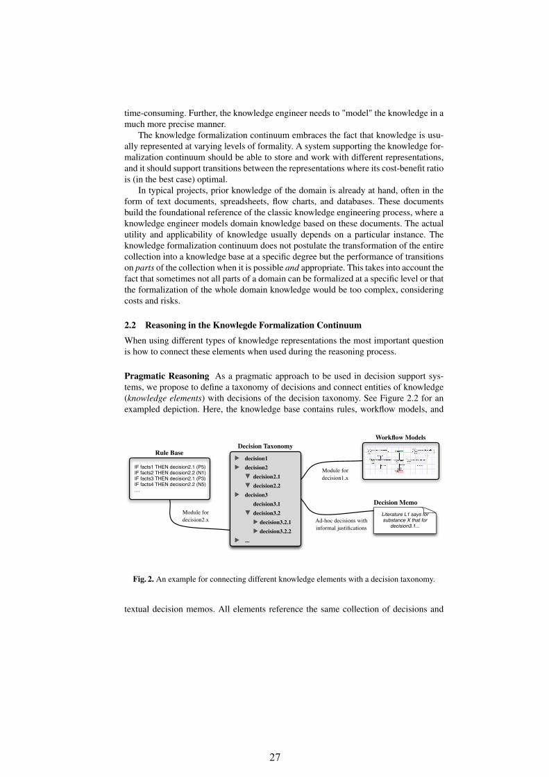
Pragmatic Reasoning As a pragmatic approach to be used in decision support sys-tems, we propose to define a taxonomy of decisions and connect entities of knowledge(knowledge elements) with decisions of the decision taxonomy. See Figure 2.2 for anexampled depiction. Here, the knowledge base contains rules, workflow models, and
▶ decision1▶ decision2
▼ decision2.1▼ decision2.2
▶ decision3decision3.1
▼ decision3.2▶ decision3.2.1 ▶ decision3.2.2
▶ ...
Decision TaxonomyRule Base
IF facts1 THEN decision2.1 (P5)IF facts2 THEN decision2.2 (N1)IF facts3 THEN decision2.1 (P3)IF facts4 THEN decision2.2 (N5)....
Module for decision2.x
Workflow Models
Module for decision1.x
Ad-hoc decisions with informal justifications
Literature L1 says for substance X that for
decision3.1...
Decision Memo
Fig. 2. An example for connecting different knowledge elements with a decision taxonomy.
textual decision memos. All elements reference the same collection of decisions and

28
thus can jointly infer decisions. When a knowledge element is activated during deci-sion making–the knowledge element fires–then the corresponding decision element isestablished and presented as derived decision.
Please note, that more formal approaches like RIF [16] do use a comparable connec-tion, i.e., decisions are formalized as concepts/instances and rules are defined to derivethe existence of the concept/instance.
Decision Making using Scoring Weights With the simple approach sketched above,decisions can be only taken categorically. For a more leveled approach, we proposeto introduce scores as weights for decisions. Scores are a well-understood weight-ing scheme in knowledge engineering [11, 7] and has a simple reasoning semantics:Each decision has an account which stores the scoring weights given to the decision byknowledge elements during the reasoning process. When a knowledge element “fires”,then the corresponding score is added to the account of the particular decision. Scoringweights included in the account are aggregated in a predefined manner. A decision ele-ment is established and shown as derived decision, when the aggregated scoring weightexceeds a given threshold.
Example: Often a reduced set of score weights S = {N3, N2, N1, 0, P1, P2, P3} is suffi-cient for developing large knowledge bases. Given the weight categories a developer canselect from seven weights N1 (weakly negative) to N3 (excluded) for negative scoringand seven weights P1 (weakly positive) to P3 (clearly established) for positive scoring.The weight 0 represents an unclear state. The score weights of a decision account areaggregated as follows: The sum of two equal weights results in the next higher category,e.g., P2 + P2 = P3. Positive and negative weights are aggregated, so that two equal scoreweights nullify each other, e.g., P2 + N2 = 0. A decision is established (confirmed), ifthe aggregation of the collected scoring weights exceeds the category P3.
P2
P1
decision1
P2
P2
P1
decision2
P2
decision3
P3
P1
P1
decision5
P3
decision4
N3
Rule Base
IF facts1 THEN decision1 (P1)IF facts2 THEN decision2 (N1)IF facts3 THEN decision4 (P3)IF facts4 THEN decision3 (N2)....
Decision Accounts
Fig. 3. Exemplary score accounts for five decisions.

29
In Figure 3 the accounts of five decisions and an excerpt of a rule base are shown.One rule fires and adds the weight P1 to the account of decision1. We see thatdecision2 and decision5 are established, since the aggregation of their collectedscoring weights exceeds the weight P3. In contrast, decision4 is not establishedbecause of the negative weight N3.
3 Episodic and Collaborative Decision Making
Complex decisions often are not made by taking one step, but are typically divided intoa number of sub-decisions. Each of them may need further research and collaborativeinteraction for clarifying details. Collaboration is necessary when a complex decisioncan only be made by joining experts from different domains into the decision process.These requirements can be fulfilled by specific extensions of a decision support system:
1. Contemporary access to the data and decisions.2. Episodic collaboration during decision making.3. Provenance of data and decisions.
3.1 Contemporary Access
Authorized persons need to be able to access the system at the same time. They shouldbe able to work with the system in order to make decisions or to retrieve already takendecisions. Contemporary access can be provided by a web-based implementation of thesystem, as for example implemented by semantic wiki systems [13]. Further examplesare collaborative ontology development environments such as WebProtégé [9, 14].
In such a distributed setting we need to consider concepts like rights managementfor access control, revision management of old versions of the knowledge, and conflictmanagement of simultaneous edits.
3.2 Episodic Collaboration
Authorized persons should be able to enter data for making a particular decision. Thedata entry needs not to be made at one time but can be partitioned over multiple sessions,i.e., decision episodes. Also, different users can enter data used for the same decision.
3.3 Provenance of Data and Decisions
When more than one person contributes to a complex decision making process andwhen the process is partitioned into episodes, then the process and reasoning shouldbe traceable and understandable by the users. This implies the documentation of thedecisions including their history but also the provenance of the data used for making thedecision (see below). Therefore, the system needs to provide versioning of the decisionsmade including a documentation by the respective users. When representing the historyand documentation of decisions by an ontology, then known approaches can be applied,for instance [10, 4].
Provenance of data and decisions is needed in collaborative and episodic environ-ments. Here, the following questions need to be clearly answered:

30
– At which time was a particular data element entered?– Who entered the data?– Which knowledge elements are responsible for a particular decision?– What is the history of a particular data and decision?– Which persons contributed to the process of a particular decision?
prov:Activity
prov:Entity
prov:Agent
wasAttributedTo
wasGeneratedByused
wasAssociatedWith
xsd:dateTime xsd:dateTime
endedAtTimestartedAtTime
Fig. 4. Simple version of the PROV ontology.
We propose the application of the PROV ontology [15] to knowledge elements andthe entities of the decision process. That way, an extensible and standardized ontologyis used to represent the use and origin of decisions. In Figure 4 the three Starting Pointclasses and properties of the PROV ontology are depicted. Here, an prov:Agentis responsible for taking an prov:Activity. The prov:Activity generates anprov:Entity, but instances of prov:Entity can be also used in (other) instancesof prov:Activity. An prov:Entity is a general representation for a thing, beingphysical, digital, conceptual, or any other kind of interpretation. We can see that answersto the questions stated above can easily be represented using the simple version of thePROV ontology, when people involved in the decision making process are representedas prov:Agent instances, entered data and the decisions themselves are representedas prov:Entity instances, and the data entry and decision episodes are representedas prov:Activities.

31
4 Case Study: KnowSEC – A System for Managing ChemicalSubstances of Ecological Concern
In this section we describe the KnowSEC project and its corresponding tool. KnowSECstands for "Managing Knowledge of Substances of Ecological Concern" and it is usedto support substance-related work and workflows within a unit of the Federal Envi-ronment Agency (Umweltbundesamt). More precisely, the tool supports decisions bya number of knowledge-based modules. In the context of the KnowSEC project onlysubstances under REACH2 are considered. For the implementation of the KnowSECproject the semantic wiki KnowWE [3] was extended by KnowSEC-specific plugins.KnowWE is a full-featured tool environment for the development of diagnostic knowl-edge bases and RDF(S) ontologies. It provides plugins for automatically testing anddebugging knowledge bases including continuous integration. For a recent overviewwe refer to [1].
Many of the requirements stated in the introduction of this paper apply to theKnowSEC project: The group is divided into sub-groups; each sub-group collabora-tively works on a number of substances. For each substance under consideration a num-ber of complex decisions need to be made concerning the safety and regulation of thesubstance. Decision making on a substance sometimes can take a couple of months oreven years, therefore support for episodic decision making is required.
4.1 Substances as Wiki Instances
Since the single substances are the primary target of decision making, every substanceunder consideration is represented by a distinct (semantic) wiki article. The articlestores relevant information of the substance such as chemical end-points, relevant liter-ature, and comments of group members. The information is entered by group membersusing (user-friendly) editors. In the background the information is silently translatedinto an ontology representation for automated reuse and processing. That way, anyinformation (e.g., alternative identifiers, end-points, paragraphs, comments) is repre-sented as an RDF triple. Consequently, the visualization of the latest changes and spe-cific overviews are easily defined by SPARQL queries [17]. The article of the imaginarysubstance "Kryptonite" is depicted in Figure 5. The article is maintained for demonstra-tion purposes and reflects by no means any real work of the agency.
At the right of the article all decision work on the substance "Kryptonite" is dis-played giving a summary of the currently taken (sub-)decisions, the comments by groupmembers, and a fact sheet showing the identifiers of the substance.
At the time of writing, KnowSEC stores more than 11,000 substances as separatewiki articles including a number of critical chemical characteristics. A small part ofthese substances are currently under decision making.
2 REACH stands for the European Community Regulation on chemicals and their safe use (EC1907/2006). The regulation handles the registration, evaluation, authorization, and restrictionof chemical substances.

32
Fig. 5. The article describing the imaginary substance "Kryptonite".
4.2 Continuous and Collaborative Decision Making
When displaying a substance article in KnowSEC, the left menu of the wiki is extendedby a decision making bar; see Figure 5. Here, all decision aspects are listed that arerelevant for the working group. When clicking on a decision aspect, the sub-aspectsof the selected aspect are shown. By selecting one of these (sub-)aspects the user caninitiate a decision form, where specific questions of the aspect are asked and decisionsare proposed automatically. These interactive decision forms are generated by explicitknowledge represented by scoring rules or DiaFlux models [5]. Any data entry andtaken decision is recorded by KnowSEC including the time and user. An explanationcomponent shows the justifications of taken decisions by visualizing the supporting dataand the acting users of the data. For the explanation the PROV ontology—as describedin Section 3.3—is applied. Users, i.e., team members, are instances of prov:Agentand entered data and (decision) memos are instances of prov:Entity. The cre-ation or edit of a (decision) memo and an interactive decision form are representedas prov:Activity instances including the corresponding edit times. A simplifieddepiction of this application is shown in Figure 6; the prefix dss (decision supportsystem) stands for the KnowSEC ontology namespace.
Explicit Knowledge and the Taxonomy of Decisions From the technical point ofview, the explicit part of the knowledge base is partitioned into modules, that are con-

33
prov:Activity
prov:Entity
prov:Agent
wasAttributedTo
wasGeneratedByused
wasAssociatedWith
xsd:dateTime
xsd:dateTime
startedAtTime
dss:DecisionMemodss:FormValue
dss:MemoEntrydss:FormEntry
Team member NN
Team member MN
dss:UserMB
dss:Decision
endedAtTime
dss:Decision-Derivation
Fig. 6. Simplified version of the applied PROV interpretation for tracing the provenance of deci-sions.
nected by a taxonomy of decision instances. Since the taxonomy is represented as anRDF ontology, it is strongly connected with the ontology of the article information (seeparagraph above). The formal versions of the aspects are implemented by knowledgebase modules and connected by the taxonomy of decision instances. Some modules areusing decision trees, other modules use scoring rules, also RDF ontologies are used.
Decision Memos For some aspects and decisions, respectively, no explicit knowledgebase is available. When the user wants to document a decision without using an explicitknowledge base, he/she is able to create a decision memo. A decision memo is, enteredby an authorized user and consists of free text, some meta-data (e.g., tags, time, etc.),and an explicit decision with a scoring weight. The decision memos are attached to thearticle of the corresponding substance. The included decision is used in the overall rea-soning process. A decision memo is an implementation of an implicit reasoning elementof the knowledge formalization continuum. An example of a decision memo can be thenote of a group member that a particular aspect was proven by a specific experimentgiving the reason for deriving a specific (sub-)decision. For instance, see the decisionmemos about the persistence of the substance "Kryptonite" being created in Figure 7.Decision memos are automatically attached to the articles of the corresponding sub-stances.
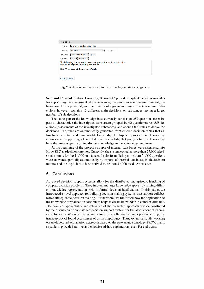
34
Fig. 7. A decision memo created for the exemplary substance Kryptonite.
Size and Current Status Currently, KnowSEC provides explicit decision modulesfor supporting the assessment of the relevance, the persistence in the environment, thebioaccumulation potential, and the toxicity of a given substance. The taxonomy of de-cisions however, contains 15 different main decisions on substances having a largernumber of sub-decisions.
The static part of the knowledge base currently consists of 282 questions (user in-puts to characterize the investigated substance) grouped by 92 questionnaires, 558 de-cisions (assessments of the investigated substance), and about 1,000 rules to derive thedecisions. The rules are automatically generated from entered decision tables that al-low for an intuitive and maintainable knowledge development process. Two knowledgeengineers are supporting a team of domain specialists, that partly define the knowledgebase themselves, partly giving domain knowledge to the knowledge engineers.
At the beginning of the project a couple of internal data bases were integrated intoKnowSEC as (decision) memos. Currently, the system contains more than 27,000 (deci-sion) memos for the 11,000 substances. In the form dialog more than 51,000 questionswere answered; partially automatically by imports of internal data bases. Both, decisionmemos and the explicit rule base derived more than 42,000 module decisions.
5 Conclusions
Advanced decision support systems allow for the distributed and episodic handling ofcomplex decision problems. They implement large knowledge spaces by mixing differ-ent knowledge representations with informal decision justifications. In this paper, weintroduced a novel approach for building decision making systems, that support collabo-rative and episodic decision making. Furthermore, we motivated how the application ofthe knowledge formalization continuum helps to create knowledge in complex domains.The practical applicability and relevance of the presented approach was demonstratedby the discussion of an installed decision support system for the assessment of chemi-cal substances. When decisions are derived in a collaborative and episodic setting, thetransparency of found decisions is of prime importance. Thus, we are currently workingon an elaborated explanation approach based on the provenance ontology PROV, that iscapable to provide intuitive and effective ad-hoc explanations even for end users.

35
References
1. Baumeister, J., Reutelshoefer, J., Belli, V., Striffler, A., Hatko, R., Friedrich, M.: KnowWE -a wiki for knowledge base development. In: The 8th Workshop on Knowledge Engineeringand Software Engineering (KESE2012). http://ceur-ws.org/Vol-949/kese8-05_04.pdf (2012)
2. Baumeister, J., Reutelshoefer, J., Puppe, F.: Engineering intelligent systems onthe knowledge formalization continuum. International Journal of Applied Math-ematics and Computer Science (AMCS) 21(1) (2011), http://ki.informatik.uni-wuerzburg.de/papers/baumeister/2011/2011-Baumeister-KFC-AMCS.pdf
3. Baumeister, J., Reutelshoefer, J., Puppe, F.: KnowWE: A semantic wiki for knowledge engi-neering. Applied Intelligence 35(3), 323–344 (2011), http://dx.doi.org/10.1007/s10489-010-0224-5
4. Franconi, E., Meyer, T., Varzinczak, I.: Semantic diff as the basis for knowledge base ver-sioning. In: 13th International Workshop on Non-Monotonic Reasoning (NMR). pp. 7–14(2010)
5. Hatko, R., Baumeister, J., Belli, V., Puppe, F.: Diaflux: A graphical language for computer-interpretable guidelines. In: Riaño, D., ten Teije, A., Miksch, S. (eds.) Knowledge Represen-tation for Health-Care, Lecture Notes in Computer Science, vol. 6924, pp. 94–107. Springer,Berlin / Heidelberg (2012)
6. Mersmann, S., Dojat, M.: SmartCaretm - automated clinical guidelines in critical care. In:ECAI’04/PAIS’04: Proceedings of the 16th European Conference on Artificial Intelligence,including Prestigious Applications of Intelligent Systems. pp. 745–749. IOS Press, Valencia,Spain (2004)
7. Miller, R.A., Pople, H.E., Myers, J.: INTERNIST-1, an Experimental Computer-Based Di-agnostic Consultant for General Internal Medicine. New England Journal of Medicine 307,468–476 (1982)
8. Milne, R., Nicol, C.: TIGER: Continuous diagnosis of gas turbines. In: ECAI’00: Proceed-ings of the 14th European Conference on Artificial Intelligence. Berlin, Germany (2000)
9. Noy, N.F., Chugh, A., Liu, W., Musen, M.A.: A framework for ontology evolution in col-laborative environments. In: ISWC’06: Proceedings of the 5th International Semantic WebConference, LNAI 4273. pp. 544–558 (2006), http://dx.doi.org/10.1007/11926078_39
10. Noy, N.F., Musen, M.A.: PromptDiff: a fixed-point algorithm for comparing ontology ver-sions. In: In 18th National Conference On Artificial Intelligence (AAAI-2002. pp. 744–750(2002)
11. Puppe, F.: Knowledge Reuse among Diagnostic Problem-Solving Methods in the Shell-KitD3. International Journal of Human-Computer Studies 49, 627–649 (1998)
12. Puppe, F., Atzmueller, M., Buscher, G., Hüttig, M., Luehrs, H., Buscher, H.P.: Applica-tion and evaluation of a medical knowledge system in sonography (SONOCONSULT). In:ECAI’08/PAIS’08: Proceedings of the 18th European Conference on Artificial Intelligence,including Prestigious Applications of Intelligent Systems. pp. 683–687. IOS Press, Amster-dam, The Netherlands, The Netherlands (2008)
13. Schaffert, S., Bry, F., Baumeister, J., Kiesel, M.: Semantic wikis. IEEE Software 25(4), 8–11(2008)
14. Tudorache, T., Nyulas, C., Noy, N.F., Musen, M.A.: WebProtégé: A collaborative ontologyeditor and knowledge acquisition tool for the web. Semantic Web (2012)
15. W3C: PROV-O: The PROV Ontology: http://www.w3.org/tr/prov-o/ (April 2013)16. W3C: RIF-Core Recommendation: http://www.w3.org/tr/rif-core/ (February 2013)17. W3C: SPARQL 1.1 recommendation: http://www.w3.org/tr/sparql11-query/ (March 2013)

36
Identifying Guidelines for Designing andEngineering Human-Centered Context-Aware
Systems(Position paper)
Emilian Pascalau
Conservatoire National des Arts et Metiers,2 rue Conte,75003 Paris, [email protected]
Abstract. In the ”future internet” environment that is generative andfosters innovation, applications are simplifying, are becoming mobile, aregetting more social and user oriented. Software design capable of copingwith such a generative environment that drives and supports innovationis still an issue. Some of the challenges of such systems include: empower-ing end-users with the necessary tools to model and develop applicationsby themselves, while in the same time hiding the technical layer fromthem. This paper introduces a set of guidelines for designing and engi-neering human-centered context-aware systems from a human computerinteraction and meta-design perspective.
1 Introduction
Recent years have brought rapid technological advances both hardware and soft-ware: increasing pervasive computing paradigm, embedded sensor technologiesand wide range of wireless and wired protocols. Applications are simplifying, arebecoming mobile, are moving to the cloud, are getting more social and user fo-cused [14]. ”Future Internet” is emerging as a new environment, an environmentthat is generative, that fosters innovation, through the advances of technologiesand a shift in people’s perception about it and a paradigm shift in how peopleact and react in this environment [22].
In this context two directions get highlighted: context together with context-awareness and human-centered computing. Studied for more than 30 years inthe field of artificial intelligence, computer and cognitive science, context hasstill been identified by Gartner, alongside cloud computing, business impact ofsocial computing, and pattern based strategy, as being one of the broad trendsthat will change IT and the economy in the next 10 years [21].
We observe a paradigm shift in terms of users of context-aware systems. Forexample a user is no longer a specific individual or organization. It is often a com-munity of collaborating, or performing similar tasks groups of users. Therefore,there is a growing need for systems meeting expectations of massive distributed

37
user base of pervasive ubiquitous devices as well as distributed cloud-based webservices.
Design and deployment of such software capable of coping with a generativeenvironment that drives and supports innovation through direct interaction andempowerment of the end-user is still an issue. Not only the development of suchsystems should be agile - the boundary is pushed even further - we need systemsthat are designed to be agile on run-time. It has been already argued (see forinstance [15]) that designers and programmers can not foresee and anticipatewhat end-users will need. Users know better what they need and future internetenvironment clearly underlines this fact.
In consequence some of the challenges of such systems that arise in the futureinternet environment include: empowering end-users with the necessary tools tomodel and develop applications by themselves, while in the same time hiding thetechnical layer from them. This paper is part of a work in progress, and identifiesand introduces a set of guidelines for designing and engineering human-centeredcontext-aware systems.
The rest of the paper is organized as follows: Section 2 discusses a use casethat is based on a concrete end-user problem (managing and tracking online pur-chases) arising from the future internet environment; the use case will support usin identifying a set of guidelines, for designing and engineering human-centeredcontext-aware systems, in Section 3; Section 4 is reserved for related work. Weconclude in section 5.
2 Application Scenario - Slice.com
In the future internet environment email communication is part of daily activi-ties. Many of the business processes that take place in a company and not onlyare started and / or integrate the actions of receiving / sending emails. In somesituations entire processes are comprised in email communications. This type ofemail based use cases are important both for academia as well as for industry.For academia from a perspective oriented towards methodology, for industryfrom a practical perspective, addressing very specific problems. Emails containknowledge that is bundled in an unstructured way but which has meaning toend-users, and which could be used to address end-user specific problems.
A human-centered context-aware system dealing with such a use case wouldbe required to provide at least the following capabilities:
– provide the means and allow the end-user to model and represent context;– allow the modeling of relationships between context elements;– allow the modeling of interactions between different contexts, this implies
both in the form of conditions and sequences of events and actions (moreprecise business rules and business processes)
– based on the provided models have the capabilities to discover in the envi-ronment the modeled context(s)
– sense events and actions that are performed in the system– perform actions according to models defined.

38
We support our previous assertions by discussing the Slice application scenario,in the next paragraphs.
Commius1 is a European research project that tackles systems for small andmedium enterprise systems (SMEs). The final goal of Commius, as argued in [5],is to turn existing email-systems into a management framework for structuredprocesses. Each incoming email is autonomously matched to a process that isenhanced with proactive annotations.
Slice.com is an industry project. Similar to Commius uses emails to tackle avery specific end-user related problem, keeping track of online purchases, thatemerged from the future internet dynamic and generative environment. Thisproject it is even more specific from the perspective of an end-user.
Slice is an online purchase management tool that gets hooked into your emailaccount. Whenever a new email is received Slice automatically analyzes thecontent of the email. If the email contains order information from one of youronline shops, then Slice via pattern-based recognition techniques extracts orderrelated contextual information and organizes this information for you. Hence allyour purchases will be gathered in one place, you will be able to keep track ofyour shopping history, amount of money that you spent, type of products, timerelated information i.e. when a shipment is about to arrive and so forth.
We analyze from an end-user perspective what this use case is about.
– Problem faced by users: keeping track of the purchases made online.– Applications involved, Services: Email as a legacy system; Services: on-
line shops (Amazon, EBay), shipment services (FedEx, UPS); Geolocationservices (Google Maps); other type of services i.e. topic extraction
– Concepts: shop, service, user, invoice, email, time and date, amount ofmoney, product, type of product, location, address, tracking number. Thelist of concepts is not exhaustive, and is up to the each user; however theseare the most obvious ones. Concepts are all those entities that are used intaking decisions and / or involved in any way in the process of resolving theend-user’s problem.
– Context: For example one context, from the perspective of an end-user inthe Slice use case, could comprise: a specific service such as FedEx; conceptsassociated with it, i.e. shipment, location, address. Further more interactionrelated to this specific context could be provided, as what to do with thisinformation and so forth.
Figure 1 depicts a general interaction process with respect to this use case.
3 Identifying Guidelines
Fisher and Giaccardi argue in [11] that in a world that is not predictable, impro-visation, evolution and innovation are a necessity. There is a shift from processestowards users. Users want their problems and their requirements to be taken into
1 http://www.commius.eu/

39
Fig. 1. General interaction process to solve the problem of keeping track of onlinepurchases
account; they want to be part of the conversation. Continuously changing busi-ness models, do not fit anymore the old and stiff approaches. Processes must bein accordance with the reality. For instance process mining techniques [20] thatlook at event logs emphasize the fact that processes which actually get executedare different compared to the original blueprints. Companies need to change towhat customers/users actually do.
Context greatly influences the way humans or machines act, the way theyreport themselves to situations and things; furthermore any change in context,causes a transformation in the experience that is going to be lived, sensed [4].Many psychological studies have shown that when humans act, and especiallywhen humans interact, they consciously and unconsciously attend to context ofmany types as stated in [12].
Traditionally context has been perceived in computer science community asa matter of location and identity, see for instance [9]. However interaction andproblems concerning interaction require more than just the environmental con-text (location, identity) used traditionally in context-aware systems [12]. Latelythe notion of context has been considered not simply as state but as part of aprocess in which users are to be involved [7].
Nardi underlines this aspect clearly in [15] stating that ”we have only scratchedthe surface of what would be possible if end users could freely program their ownapplications... As has been shown time and again, no matter how much design-ers and programmers try to anticipate and provide for what users will need, theeffort always falls short because it is impossible to know in advance what may beneeded... End users should have the ability to create customizations, extensionsand applications...”.
From a human-centered computing perspective this type of system is whatDonald Norman calls in [16] the type of system, where the system itself disap-pears from sight, and humans (end-users) can once again concentrate upon theiractivities and their goals.
Grundin [12] continues and argues that aggregation or interpretation doneby software systems are different than aggregation and interpretation done bybiological, psychological and social processes.
Meta-design is a conceptual framework defining and creating social and tech-nical infrastructures in which new forms of collaborative design can take place[11]. Meta-design originates in human computer interaction field and tacklesend-user development.

40
Table 1, introduced in [11] compares side by side traditional design vs. meta-design. However, in our perspective a human-centered context-aware system, inorder to provide a high degree of generality and to avoid re-implementation ofcommon things related to infrastructure, should be a layered system as discussedin [18]. A low level that is very technical and should be hidden from the end-user.This low level would follow to great extent traditional design. The high level onthe other hand should follow mainly meta-design. A translation mechanism hasto be put into place to assure translation between these two layers.
Table 1. Traditional Design vs. Meta-Design [11]
Traditional Design Meta-Design
guidelines and rules exceptions and negations
representation construction
content context
object process
perspective immersion
certainty contingency
planning emergence
top-down bottom-up
complete system seeding
autonomous creation co-creation
autonomous mind distributed mind
specific solutions solutions spaces
design-as-instrumental design-as-adaptive
accountability, know-what (rational deci-sioning)
affective model, know-how (embodied in-teractionism)
Fig. 2. Context requirements
Several definitions for the concept context have been enunciated; Fischer,however gives a definition that takes into account the human-centered computa-tional environments. He defines context in [10] as being the ’right’ information,at the ’right’ time, in the ’right’ place, in the ’right’ way to the ’right’ person.

41
Figure 2 depicts aspects that have been identified in [1] as requirements fordealing with context.
Table 2, introduced in [10] depicts adaptive and adaptable systems. Con-text aware systems traditionally position themselves, according to Table 2 inthe category of adaptive systems. These systems employ users’ profiles informa-tion and other type of contextual information, like location to improve users’experience. These approaches, although they provide a degree of flexibility, arehowever still stiff approaches because they are still based on predefined designsand very specific.
Table 2. Adaptive vs. Adaptable Systems [10]
Adaptive Adaptable
definition dynamic adaptation by thesystem itself to current taskand current user
users change the functional-ity of the system
knowledge contained in the system;projected in different ways
knowledge is extended byusers
strengths little (or no) effort by users;no special knowledge ofusers is required
users are in control; usersknow their tasks best
weaknesses users often have difficultiesdeveloping a coherent modelof the system; loss of control
users must do substan-tial work; complexity isincreased (users need tolearn adaptation compo-nents); systems may becomeincompatible
mechanisms required models of users, tasks, di-alogs; incremental update ofmodels
support for end-user modifi-ability and development
application domains active help, critiquing sys-tems, recommender systems
end-user modifibiality, tai-lorability, design in use,meta-design
In our vision a human-centered context-aware system is a system where adap-tivity and adaptability are blended together. By such a method users will be ableto directly model how the context should look like for a particular problem, andafterwards the system would be required only to verify that the specified con-text really exists in a given environment. Moreover while for adaptive systemsas stated in [3] the architecture of such systems comprises a user model (userperspective on the problem) and a domain model (system perspective as it hasbeen designed), for a human-centered context-aware system there should be onlyone conceptual model of the problem, that should be shared and understood inthe same way both by the end-user and the system.

42
Fig. 3. Interrelated topics
Figure 3 depicts the main perspectives that need to be blended together inorder to design a human-centered context-aware system. This particular viewhas its roots in the meta-design conceptual framework [11].
Aspect Oriented Programming [19] is a relatively new methodology for soft-ware development that aims at providing software modularity by means of sepa-ration of cross cutting concerns. This is an approach for requirements engineeringthat focuses on customers concerns to be made consistent with aspect orientedsoftware development. In terms of software engineering throughout the codethere are specifically designed points that support adaptation based on definedaspects.
The authors in [8] discuss how aspect orientation and can be used in contextaware systems design. Furthermore because in aspect oriented programming di-rect user input is taken into account this is an example of human-centered contextaware systems. However this approach although it goes into the right directionit is restricted by the predefined points that support aspect orientation in theimplemented code.
Based on the analysis made the design and engineering process of human-centered context-aware systems should follow the following guidelines:
1. such a system should be as general as possible and should be able to tackleas many problems as possible [11];
2. such a system should should provide the right level of representation suchthat a problem representation could be automatically translated into thecore constructs of the underlying programming language in which the overallsystem is implemented;
3. such systems should not be domain specific and therefor closed system, butan open system that could be used to address a wide range of problems andapplications;

43
4. in such a system the focus should be on the needs of the end-user and noton the system itself; the system should be hidden from the end-user;
5. such a system should be designed for evolution and should provide the meansto evolve through the input of users, as well as by itself;
6. such a system should support both skilled domain workers as well as noviceusers;
7. such a system should be a co-adaptive environment where users change be-cause they learn and systems change because users become co-developers;
8. such a system should allow active participation and empowerment of end-users;
9. in such a system the end-user should be the coordinator of how the systemworks.
Some of the guidelines refer to the relationship between system and the end-user, and some concern just the system. The system that we envision is similar toan operating system in terms of being general and not domain specific. The sys-tem will be an intelligent one and will accept problem descriptions given by theend-users. These descriptions will act as application models. Such a descriptiontogether with the intelligent system will make the application. We have alreadymade initial steps towards implementing such a system in [18], [17].
4 Related Work
Context awareness has been studied for several decades from many perspectives.Development of context-aware application, however, is still very difficult andtime consuming and aside location-based services, not too many applicationshave been put into real use.
A series of surveys addressing different aspects (i.e. context modeling andcontext-based reasoning, context-aware frameworks and applications, context-aware web services) of development of context-aware systems and their applica-tions have been developed. We observe that the present approaches to contextreasoning and context-aware system design are only partial, in most of the casesbeing too specific, or too generic.
Types of context used and models of context information systems that sup-port collecting and disseminating context, and applications that adapt to thechanging context have been addressed by Chen and Kotz in [6].
Bolchini et al. discuss in [4] general analysis framework for context mod-els and a comparison of some of the data-oriented approaches available in theliterature. The framework addresses: modeled aspects of context (space, time,absolute/relative, history, subject, user profile), representation features (typeof formalism, level of formality, flexibility, granularity, constraints) and contextmanagement and usage (construction, reasoning, information quality monitor-ing, ambiguity, automatic learning features, multi-context modeling).
A unified architectural model and a new taxonomy for context data distri-bution has been discussed in [2]. Authors identify 3 major aspects: (1) context

44
data distribution should take into account node requests and quality of contextrequirements to reduce management overhead; (2) context data distribution re-quires adaptive and crosscutting solutions able to orchestrate the principal in-ternal facilities according to specific management goals; (3) informed contextdata distribution can benefit from their increased context-awareness to furtherenhance system scalability and reliability.
The impact of context-awareness on service engineering has also been noticed.A classic and relatively recent survey [13] by Kapitsaki et al. considers context asconstituting an essential part of service behavior, especially with the interactionof users. They observe that ”at the heart of every context-aware service, relevantbusiness logic has to be executed and (. . . ) adapted to context changes”.
Related work concerning this human-centered context-aware perspective, asit was analyzed in this paper is to the best of our knowledge only in an earlystage.
5 Conclusions
In this paper we have started an initial discussion about the design and en-gineering of human-centered context-aware systems. Aspects discussed in thispaper are part of a work in progress. Our previous experience [18], [17] withdeveloping human-centered context-aware systems proved to be not trivial. Thisdiscussion comprised aspects from human computer interaction, meta-design,context and context-awareness. We have emphasized the fact that systems pre-designed can not foresee all aspects and facets of a problem. Therefore end-usershould be given the necessary tools to design and develop their own solutionsbased on existing services. We provide a set of guidelines and properties thatshould characterize such human-centered context-aware systems.
Next steps include formalizing a conceptual framework, methodology and im-plementation guidelines for developing such a system that is capable of tacklingin a unified way the problem of development of human-centered context-awareapplications.
References
1. Christos B. Anagnostopoulos, Athanasios Tsounis, and Stathes Hadjiefthymiades.Context awareness in mobile computing environments. Wireless Personal Com-munications, 42(3):445–464, 2007.
2. Paolo Bellavista, Antonio Corradi, Mario Fanelli, and Luca Foschini. A survey ofcontext data distribution for mobile ubiquitous systems. ACM Computing Surveys(CSUR), 44(4):50 pages, 2012.
3. David Benyon and Dianne Murray. Applying user modeling to human-computerinteraction design. Artificial Intelligence Review, 7(3-4):199–225, 1993.
4. Cristiana Bolchini, Carlo A. Curino, Elisa Quintarelli, Fabio A. Schreiber, andLetizia Tanca. A data-oriented survey of context models. ACM SIGMOD Record,36(4):19–26, 2007.

45
5. Thomas Burkhart, Dirk Werth, and Peter Loos. Context-sensitive business processsupport based on emails. In WWW 2012 – EMAIL’12 Workshop, April 2012.
6. Guanling Chen and David Kotz. A survey of context-aware mobile computingresearch. Technical report, Dartmouth College Hanover, NH, USA, 2000.
7. Joelle Coutaz, James L. Crowley, Simon Dobson, and David Garlan. Context iskey. Communications of the ACM - The disappearing computer, 48(3):49–53, 2005.
8. Abhay Daftari, Nehal Mehta, and Shubhanan Bakre Xian-He Sun. On designframework of context aware embedded systems. In Monterey Workshop on SoftwareEngineering for Embedded Systems: From Requirements to Implementation, 2003.
9. Anind K. Dey and Gregory D. Abowd. Towards a better understanding of contextand context-awareness. In In HUC ’99: Proceedings of the 1st international sym-posium on Handheld and Ubiquitous Computing, pages 304–307. Springer-Verlag,1999.
10. Gerhard Fischer. Context-aware systems - the ’right’ information, at the ’right’time, in the ’right’ place, in the ’right’ way, to the ’right’ person. In AVI’12. ACM,2012.
11. Gerhard Fischer and Elisa Giaccardi. End User Development - Empowering Peopleto Flexibly Employ Advanced Information and Communication Technology, chapterMeta-Design: A Framework fo the Future of the End-User Development. KluwerAcademic Publishers, 2004.
12. Jonathan Grudin. Desituating action: digital representation of context. Human-Computer Interaction, 16(2):269–286, 2001.
13. Georgia M. Kapitsaki, George N. Prezerakos, Nikolaos D. Tselikas, and Iakovos S.Venieris. Context-aware service engineering: A survey. The Journal of Systemsand Software, 82(8):1285–1297, 2009.
14. Charles McLellan, Teena Hammond, Larry Dignan, Jason Hiner, Jody Gilbert,Steve Ranger, Patrick Gray, Kevin Kwang, and Spandas Lui. The Evolution ofEnterprise Software. ZDNet and TechRepublic, 2013.
15. Bonnie A. Nardi. A Small Matter of Programming: Perspectives on End UserComputing. MIT Press, 1993.
16. Donald A. Norman. The Invisible Computer. MIT Press, 1999.17. Emilian Pascalau. Mashups: Behavior in context(s). In Proceedings of 7th Work-
shop on Knowledge Engineering and Software Engineering (KESE7) at the 14thConference of the Spanish Association for Artificial Intelligence (CAEPIA 2011),volume 805, pages 29–39. CEUR-WS, 2011.
18. Emilian Pascalau. Towards TomTom like systems for the web: a novel architecturefor browser-based mashups. In Proceedings of the 2nd International Workshop onBusiness intelligencE and the WEB (BEWEB11), pages 44–47. ACM New York,NY, USA, 2011.
19. Ian Sommerville. Software Engineering 8. Addison Wesley, 2007.20. W. M. P. van der Aalst, B. F. van Dongen, J. Herbst, L. Maruster, G. Schimm,
and A. J. M. M. Weijters. Workflow mining: a survey of issues and approaches.Data & Knowledge Engineering, 47(2):237–267, 2003.
21. Min Wang. Context-aware analytics: from applications to a systemframework. http://e-research.csm.vu.edu.au/files/apweb2012/download/APWeb-Keynote-Min.pdf, 2012.
22. Jonathan Zittrain. The Future of the Internet And How to Stop It. Yale UniversityPress New Haven and London, 2008.

46
Overview of Recommendation Techniquesin Business Process Modeling?
Krzysztof Kluza, Mateusz Baran, Szymon Bobek, Grzegorz J. Nalepa
AGH University of Science and Technology,al. A. Mickiewicza 30, 30-059 Krakow, Poland
{kluza,matb,s.bobek,gjn}@agh.edu.pl
Abstract Modeling business processes is an important issue in Business ProcessManagement. As model repositories often contain similar or related models, theyshould be used when modeling new processes. The goal of this paper is to pro-vide an overview of recommendation possibilities for business process models.We introduce a categorization and give examples of recommendation approaches.For these approaches, we present several machine learning methods which can beused for recommending features of business process models.
1 Introduction
Business Process (BP) models are visual representations of processes in an organiza-tion. Such models can help to manage process complexity and are also easy to un-derstand for non-business user. Although there are many new tools and methodologieswhich support process modeling, especially using Business Process Model and Nota-tion (BPMN) [1], they do not support recommendation mechanisms for BP modelers.
As BPMN specifies only a notation, there can be several ways of using it. There arestyle directions how to model BPs [2], or guidelines for analysts based on BPs under-standability (e.g. [3]). However, a proper business process modeling is still a challeng-ing task, especially for inexperienced users.
Recommendation methods in BP modeling can address this problem. Based on cur-rent progress or additional pieces of information, various features can be recommendedto a modeler, and he/she can be assisted during designing models. Such assistance canprovide autocompleting mechanisms with capabilities of choosing next process frag-ments from suggested ones. Names of model elements or attachments can be recom-mended as well. Such approaches can reduce number of errors during process design aswell as speed up modeling process. It also supports reusing of existing process models,especially when a process repository is provided.
The rest of this paper is organized as follows: In Section 2, we provide a cate-gorization of recommendation methods used in business process modeling. Section 3describes the current state of the art in this research area. Selected machine learningmethods that can be used for recommending features of process models are presentedin Section 4. Section 5 presents an example which can be considered as a suitable casestudy for recommendation purposes. The paper is summarized in Section 6.? The paper is supported by the Prosecco project.

47
2 Types of recommendations
Basically, recommendation methods in BPs modeling can be classified as one of twotypes: subject-based and position-based classification. The first one concentrates onwhat is actually suggested, while the second one focuses on the place where the sug-gestion is to be placed. However, they are suited for different purposes and thereforeare complementary. A hierarchy of the identified types of recommendation methods ispresented in Figure 1.
2.1 Subject-based classification
In subject-based classification we focus on what is actually suggested. The suggestionitself is not directly dependent on the context it is placed in. The recommendation algo-rithms may actually inspect the context to be able to deliver more accurate results but itis not an inherent feature of recommended item.
1. Attachment recommendations – as the name suggests, these recommendationssuggest how to link a business process (or, more precisely, a selected element of it)with an external entity like a decision table or another process. Attachment recom-mendations appear naturally where user should link two already existing items.
(a) Decision tables – recommendations for a decision table describing conditionsin a gate. See an example in Figure 2.
Figure 2. Decision table suggestion
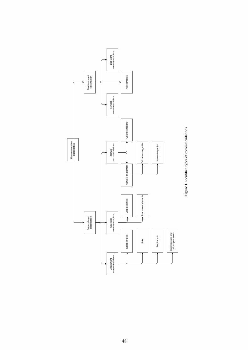
48
Rec
omm
enda
tion
clas
sific
atio
n
Text
ual
reco
mm
enda
tions
Posi
tion-
base
d cl
assi
ficat
ion
Stru
ctur
al
reco
mm
enda
tions
Forw
ard
reco
mm
enda
tions
Back
war
d re
com
men
datio
ns
Auto
com
plet
eN
ame
of a
n el
emen
t
Nam
e co
mpl
etio
n
Full
nam
e su
gges
tion
Serv
ice
task
Subp
roce
sses
and
ca
ll su
bpro
cess
es
Link
s
Gua
rd c
ondi
tions
Dec
isio
n ta
ble
Sing
le e
lem
ent
Stru
ctur
e of
ele
men
ts
Atta
chm
ent
reco
mm
enda
tions
Subj
ect-b
ased
cl
assi
ficat
ion
Figu
re1.
Iden
tified
type
sof
reco
mm
enda
tions
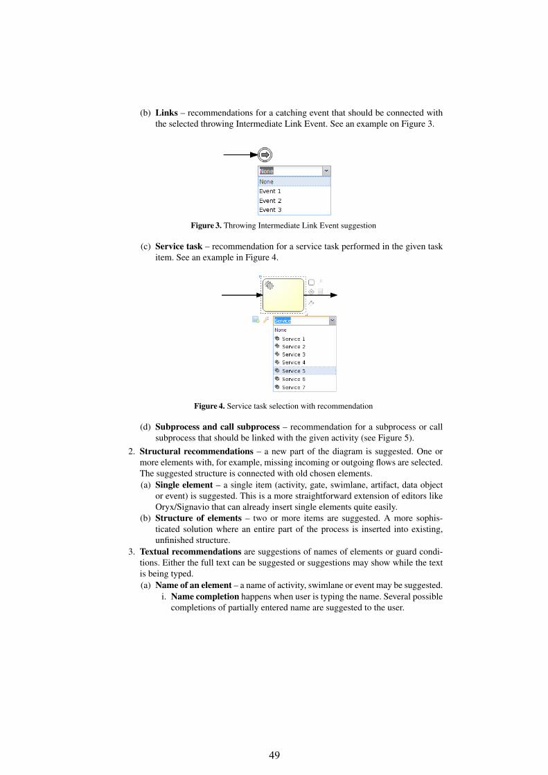
49
(b) Links – recommendations for a catching event that should be connected withthe selected throwing Intermediate Link Event. See an example on Figure 3.
Figure 3. Throwing Intermediate Link Event suggestion
(c) Service task – recommendation for a service task performed in the given taskitem. See an example in Figure 4.
Figure 4. Service task selection with recommendation
(d) Subprocess and call subprocess – recommendation for a subprocess or callsubprocess that should be linked with the given activity (see Figure 5).
2. Structural recommendations – a new part of the diagram is suggested. One ormore elements with, for example, missing incoming or outgoing flows are selected.The suggested structure is connected with old chosen elements.(a) Single element – a single item (activity, gate, swimlane, artifact, data object
or event) is suggested. This is a more straightforward extension of editors likeOryx/Signavio that can already insert single elements quite easily.
(b) Structure of elements – two or more items are suggested. A more sophis-ticated solution where an entire part of the process is inserted into existing,unfinished structure.
3. Textual recommendations are suggestions of names of elements or guard condi-tions. Either the full text can be suggested or suggestions may show while the textis being typed.(a) Name of an element – a name of activity, swimlane or event may be suggested.
i. Name completion happens when user is typing the name. Several possiblecompletions of partially entered name are suggested to the user.
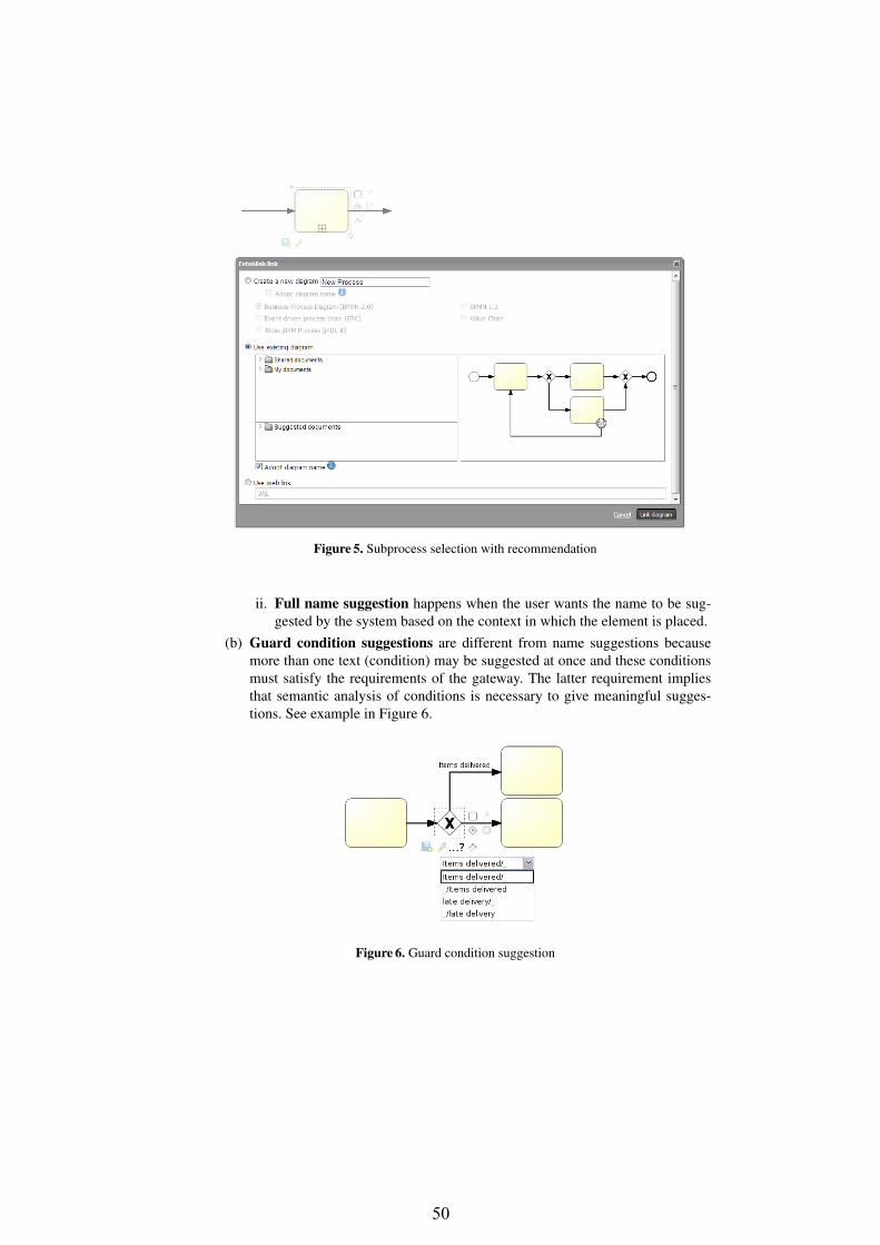
50
Figure 5. Subprocess selection with recommendation
ii. Full name suggestion happens when the user wants the name to be sug-gested by the system based on the context in which the element is placed.
(b) Guard condition suggestions are different from name suggestions becausemore than one text (condition) may be suggested at once and these conditionsmust satisfy the requirements of the gateway. The latter requirement impliesthat semantic analysis of conditions is necessary to give meaningful sugges-tions. See example in Figure 6.
Figure 6. Guard condition suggestion

51
2.2 Position-based classification1. Forward completion – a part of the process is known and the rest of the process,
starting with one selected activity, is to be suggested. See Figure 7.
Figure 7. Forward completion
2. Backward completion – a part of the process is known and the rest of the process,ending with one selected activity, is to be suggested. See Figure 8.
Figure 8. Backward completion
3. Autocomplete – a part of the process is known and the rest of the process is tobe suggested. A number of items with no outgoing or incoming flows is selected –missing flows will lead to or from the suggested structure. See Figure 9.
Figure 9. Autocompletion

52
3 Recommendation Techniques for Business Process Models
Empirical studies have proven that modelers prefered to receive and use recommen-dation suggestions during design [4]. Recommendations can be based on many fac-tors, including labels of elements, current progress of modeling process, or some ad-ditional pieces of information, such as process description. There are several existingapproaches which can be assigned to the following subject-based categories:
1. Attachment recommendations: Born et al. [5] presented an approach that sup-ports modelers during modeling tasks by finding appropriate services, meaningfulto the modeler. More complex approach which helps process designers facilitatemodeling by providing them a list of related services to the current designed modelwas proposed by Nguyen et al. [6]. They capture the requested service’s compo-sition context specified by the process fragment and recommend the services thatbest match the given context. The authors also described an architecture of a recom-mender system which bases on historical usage data for web service discovery [7].
2. Structural recommendations: Mazanek et al. [8] proposed a syntax-based assis-tance in diagram editor which takes advantage of graph grammars for process mod-els. Based on this research they proposed also a sketch-based diagram editor withuser assistance based on graph transformation and graph drawing techniques [9].Hornung et al. [10] presented the idea of interpreting process descriptions as tagsand based on them provide a search interface to process models stored in a repos-itory. Koschmider and Oberweis extended this idea in [11] and presented theirrecommendation-based editor for business process modeling in [4]. The editor as-sists users by providing search functionality via a query interface for business pro-cess models or process model parts and using automatic tagging mechanism inorder to unveil the modeling intention of a user at process modeling time. An ap-proach proposed by Wieloch et al. [12] delivers a list of suggestions for possi-ble successor tasks or process fragments based on analysis of context and annota-tions of process tasks. Case based reasoning for workflow adaptation was discussedin [13]. It allows for structural adaptations of workflow instances at build time orat run time. The approach supports the designer in performing such adaptations byan automated method based on the adaptation episodes from the past. The recordedchanges can be automatically transferred to a new workflow that is in a similarsituation of change.
3. Textual recommendations: Naming strategies for individual model fragments andwhole process models was investigated in [14] They proposed an automatic namingapproach that builds on the linguistic analysis of process models from industry. Thisallows for refactoring of activity labels in business process models [15].According to Kopp et al. [16] it is not to automatically deduct concrete conditionson the sequence flows going out from the new root activity as we cannot guess theintention of the fragment designer. However, they presented how a single BPMNfragment can be completed to a BPMN process using autocompletion of modelfragments, where the types of the joins are AND, OR, and XOR.

53
4 Machine Learning Approach for RecommendationThe idea of recommender systems was evolving along with a rapid evolution of theInternet in mid-nineties. Methods such as collaborative filtering, content-based andknowledge-based recommendation [17] gained huge popularity in the area of web ser-vices [18] and recently most often in context-aware systems [19]. The principal rulethat most of the recommendation methods are based on, exploits an idea of similaritiesmeasures. This measures can be easily applied to items that features can be extracted(eg. book genre, price, author) and ranked according to some metrics (customer likedthe book or not). However, when applied to BPMN diagrams, common recommendersystems face a big problem of non existence of standard metrics that will allow forcomparison of models. What is more, feature extraction of the BPMN diagrams thatwill allow for precise and unambiguous description of models is very challenging and,to our knowledge, still unsolved issue.
Therefore, other machine learning methods should be investigated according to anobjective aiming at providing recommendation mechanisms for a designer. The follow-ing Section contains an analysis of possible application of machine learning methods torecommendations described in Section 2. A comprehensive summary is also providedin Table 1. The black circle denotes full support of particular machine learning methodto recommendation; half-circle denoted partial support of particular machine learningmethod to recommendation, and empty circle means no, or very limited support.
Clusteringalgorithmsa
Decisiontreesb
Bayesiannetworksc
Markovchains
Attachment recommendations m l m m
Structural recommendations m l l l
Textual recommendations m m w l
Position based classification m l l l
Table 1. Comparison of different machine learning methods for recommending features denotedin Section 2
a Useless as an individual recommendation mechanism, but can boost recommendation whencombined with other methods
b No cycles in diagramc No cycles in diagram
4.1 ClassificationClustering methods Clustering methods [20] are based on optimization task that canbe described as an minimization of a cost function that are given by the equation 1. Kdenotes number of clusters that the data set should be divided into.
N∑n=1
K∑k=1
‖Xn − µn‖2 (1)
This cost function assume existence of a function f that allows for mapping element’sfeatures into an M dimensional space of X ∈ Rm. This however requires develop-ing methods for feature extraction from BPMN diagrams, which is not trivial and still

54
unsolved task. Nevertheless, clustering methods can not be used directly for recommen-dation, but can be very useful with combination with other methods.
Decision trees Decision trees [21] provide a powerful classification tool that exploitsthe tree data structure to represent data. The most common approach for building a tree,assumes possibility of calculation entropy (or based on it, so-called information gain)that is given by the equation 2.
E(X) = −n∑
i=1
p(xi)log(p(xi))) (2)
To calculate the entropy, and thus to build a decision tree, only a probability p ofpresence of some features in a given element is required. For the BPMN diagram, thosefeatures could be diagram nodes (gateways, tasks, etc) represented by a distinct realnumbers. Having a great number of learning examples (diagrams previously build bythe user), it is possible to build a tree that can be used for predicting next possibleelement in the BPMN diagram. However, the nature of the tree structure requires fromBPMN diagram to not have cycles, which not always can be guaranteed.
4.2 Probabilistic Graphical Models
Probabilistic Graphical Models use a graph-based representation as the basis for com-pactly encoding a complex probability distribution over a high dimensional space [22].The most important advantage of probabilistic graphical models over methods describedin Section 4.1 is that it is possible to directly exploit the graphical representation of BPdiagrams, which can be almost immediately translated into such model.
Bayesian networks Bayesian network (BN) [23] is an acyclic graph that representsdependencies between random variables, and provide graphical representation of theprobabilistic model. The example of a Bayesian network is presented in Figure 10.
G1
B1
B2
G2
Figure 10. Bayesian network
The advantage of BN is that the output of a recommendation is a set of probabilities,allowing for ranking the suggestion from the most probable to the least probable. Forexample to calculate the probability of the value of the random variable B1 from theFigure 10, the equation 3 can be used. The G1,2 can be denoted as BPMN gateways,and B1,2 as other blocks, e.g. Tasks or Events. Thus, having any of these blocks given,we can calculate a probability of a particular block being a missing part.
P (B1) =∑G1
∑G2
∑B2
P (G1)P (B1|G1)P (B2|G1)P (G2|B1, B2) (3)
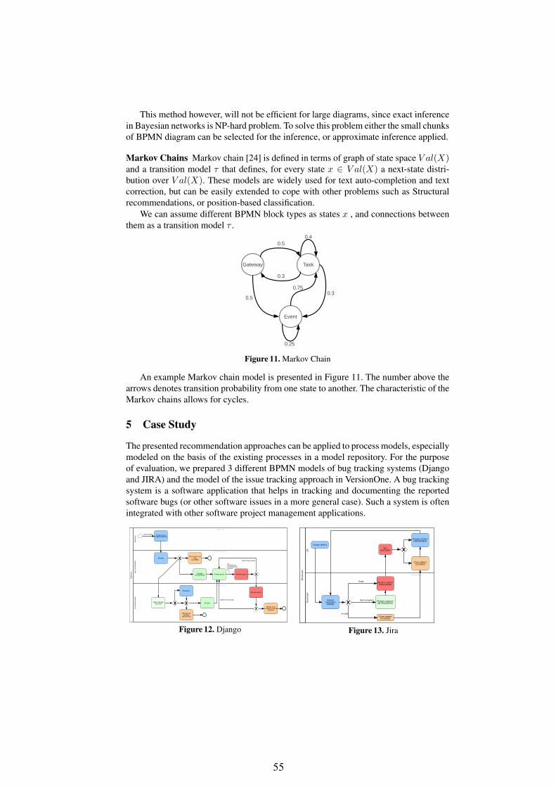
55
This method however, will not be efficient for large diagrams, since exact inferencein Bayesian networks is NP-hard problem. To solve this problem either the small chunksof BPMN diagram can be selected for the inference, or approximate inference applied.
Markov Chains Markov chain [24] is defined in terms of graph of state space V al(X)and a transition model τ that defines, for every state x ∈ V al(X) a next-state distri-bution over V al(X). These models are widely used for text auto-completion and textcorrection, but can be easily extended to cope with other problems such as Structuralrecommendations, or position-based classification.
We can assume different BPMN block types as states x , and connections betweenthem as a transition model τ .
Gateway Task
Event
0.25
0.75
0.4
0.3
0.3
0.5
0.5
Figure 11. Markov Chain
An example Markov chain model is presented in Figure 11. The number above thearrows denotes transition probability from one state to another. The characteristic of theMarkov chains allows for cycles.
5 Case Study
The presented recommendation approaches can be applied to process models, especiallymodeled on the basis of the existing processes in a model repository. For the purposeof evaluation, we prepared 3 different BPMN models of bug tracking systems (Djangoand JIRA) and the model of the issue tracking approach in VersionOne. A bug trackingsystem is a software application that helps in tracking and documenting the reportedsoftware bugs (or other software issues in a more general case). Such a system is oftenintegrated with other software project management applications.
Report
er
Core
Develo
per
Core Developer
Make DesignDecision Accept
Review patch
Merge andresolve as fixed
[FIXED]
Resolve aswontfix
[WONTFIX]
Postpone
Report
er
Reporter
Create Issue[UNREVIEWED]
Any C
ontr
ibuto
r
Any Contributor
Close with anyflag
[CLOSED]
Accept[ACCEPTED] Create patch Review patch
Review
Cannot bereviewed byauthor
Unreviewed
patch has issues
patch has issues
Figure 12. Django
Develo
per
Develo
per
Developer
Assessresolution
[OPEN]
Close defect[CLOSED]
Resolve defect[RESOLVED]
Prepare solution[IN PROGRESS]
QA
QA
Create defect
Testresolution
Close defect[CLOSED]
Reopen defect[REOPENED]
fixed
invalid
start progress
Figure 13. Jira

56
QA
, B
A, Le
ader
QA
, B
A, Le
ader QA, BA, Leader
Create defect[OPEN]
Leader
Leader
Assigndefect
Move defect tofuture iteration
[FUTURE]
Develo
per
Developer
Prepare defectsolution
[IN PROGRESS]
Commitdefect
solution[DONE]
Assesresolution
Point at buildnumber with
resolution[PENDING
TEST]
Prepare for workon defect[PENDINGANALYSIS]
Analyze defectcause
[IN ANALYSIS]
Removeblockages[BLOCKED]
QA
QA
Test resolution[IN TEST]
Accept[ACCEPTED]
Removeblockages[BLOCKED]
Reject[REJECTED]
Close defect[CLOSED]
start analysys
blocking issues
quick fix available
As designed
tests failed
blocking issues
Defect still occurs
Figure 14. VersionOne
We selected such models as a case study because of their similarity. As the processesof different bug trackers present the existing variability, such example can be easily usedto present for recommendation purposes when modeling a new bug tracking flow fora bucktracking system.
6 Conclusion and future workThis paper focuses on a problem of recommendation methods in BP modeling. Suchmethods help in speeding up modeling process and producing less error prone mod-els than modeling from scratch. The original contribution of the paper is introducinga categorization of recommendation approaches in BP modeling and short overview ofmachine learning methods corresponding to the presented recommendations.
Our future work will focus on specifying recommendation approach for companymanagement systems in order to enhance modeling process and evaluation of the se-lected recommendation methods. We plan to carry out a set of experiments aiming attesting recommendation approaches on various model sets.
References
1. OMG: Business Process Model and Notation (BPMN): Version 2.0 specification. TechnicalReport formal/2011-01-03, Object Management Group (2011)
2. Silver, B.: BPMN Method and Style. Cody-Cassidy Press (2009)3. Mendling, J., Reijers, H.A., van der Aalst, W.M.P.: Seven process modeling guidelines
(7pmg). Information & Software Technology 52 (2010) 127–1364. Koschmider, A., Hornung, T., Oberweis, A.: Recommendation-based editor for business
process modeling. Data & Knowledge Engineering 70 (2011) 483 – 5035. Born, M., Brelage, C., Markovic, I., Pfeiffer, D., Weber, I.: Auto-completion for executable
business process models. In Ardagna, D., Mecella, M., Yang, J., eds.: Business ProcessManagement Workshops. Volume 17 of Lecture Notes in Business Information Processing.Springer Berlin Heidelberg (2009) 510–515
6. Chan, N., Gaaloul, W., Tata, S.: Context-based service recommendation for assisting busi-ness process design. In Huemer, C., Setzer, T., eds.: E-Commerce and Web Technologies.Volume 85 of Lecture Notes in Business Information Processing. Springer Berlin Heidelberg(2011) 39–51

57
7. Chan, N., Gaaloul, W., Tata, S.: A recommender system based on historical usage data forweb service discovery. Service Oriented Computing and Applications 6 (2012) 51–63
8. Mazanek, S., Minas, M.: Business process models as a showcase for syntax-based assistancein diagram editors. In: Proceedings of the 12th International Conference on Model DrivenEngineering Languages and Systems. MODELS ’09, Berlin, Heidelberg, Springer-Verlag(2009) 322–336
9. Mazanek, S., Rutetzki, C., Minas, M.: Sketch-based diagram editors with user assistancebased on graph transformation and graph drawing techniques. In de Lara, J., Varro, D., eds.:Proceedings of the Fourth International Workshop on Graph-Based Tools (GraBaTs 2010),University of Twente, Enschede, The Netherlands, September 28, 2010. Satellite event ofICGT’10. Volume 32 of Electronic Communications of the EASST. (2010)
10. Hornung, T., Koschmider, A., Lausen, G.: Recommendation based process modeling sup-port: Method and user experience. In: Proceedings of the 27th International Conference onConceptual Modeling. ER ’08, Berlin, Heidelberg, Springer-Verlag (2008) 265–278
11. Koschmider, A., Oberweis, A.: Designing business processes with a recommendation-basededitor. In Brocke, J., Rosemann, M., eds.: Handbook on Business Process Management 1.International Handbooks on Information Systems. Springer Berlin Heidelberg (2010) 299–312
12. Wieloch, K., Filipowska, A., Kaczmarek, M.: Autocompletion for business process mod-elling. In Abramowicz, W., Maciaszek, L., Wecel, K., eds.: Business Information SystemsWorkshops. Volume 97 of Lecture Notes in Business Information Processing. SpringerBerlin Heidelberg (2011) 30–40
13. Minor, M., Bergmann, R., Görg, S., Walter, K.: Towards case-based adaptation of workflows.In Bichindaritz, I., Montani, S., eds.: ICCBR. Volume 6176 of Lecture Notes in ComputerScience., Springer (2010) 421–435
14. Leopold, H., Mendling, J., Reijers, H.A.: On the automatic labeling of process models. InMouratidis, H., Rolland, C., eds.: Advanced Information Systems Engineering. Volume 6741of Lecture Notes in Computer Science. Springer Berlin Heidelberg (2011) 512–520
15. Leopold, H., Smirnov, S., Mendling, J.: On the refactoring of activity labels in businessprocess models. Information Systems 37 (2012) 443–459
16. Kopp, O., Leymann, F., Schumm, D., Unger, T.: On bpmn process fragment auto-completion.In Eichhorn, D., Koschmider, A., Zhang, H., eds.: Services und ihre Komposition. Proceed-ings of the 3rd Central-European Workshop on Services and their Composition, ZEUS 2011,Karlsruhe, Germany, February 21/22. Volume 705 of CEUR Workshop Proceedings., CEUR(2011) 58–64
17. Jannach, D., Zanker, M., Felfernig, A., Friedrich, G.: Recommender Systems An Introduc-tion. Cambridge University Press (2011)
18. Wei, K., Huang, J., Fu, S.: A survey of e-commerce recommender systems. In: ServiceSystems and Service Management, 2007 International Conference on. (2007) 1–5
19. Bobek, S., Nalepa, G.J.: Overview of context-aware reasoning solutions for mobile devices.proposal of a rule-based approach. Computer Science and Information Systems (2014) ac-cepted.
20. Bishop, C.M.: Pattern Recognition and Machine Learning (Information Science and Statis-tics). Springer-Verlag New York, Inc., Secaucus, NJ, USA (2006)
21. Mitchell, T.M.: Machine Learning. MIT Press and The McGraw-Hill companies, Inc. (1997)22. Koller, D., Friedman, N.: Probabilistic Graphical Models: Principles and Techniques. MIT
Press (2009)23. Friedman, N., Geiger, D., Goldszmidt, M.: Bayesian network classifiers. Machine Learning
29 (1997) 131–16324. Rabiner, L., Juang, B.H.: An introduction to hidden markov models. ASSP Magazine, IEEE
3 (1986) 4–16

58
A PROLOG Frameworkfor Integrating Business Rules into JAVA Applications
Ludwig Ostermayer, Dietmar Seipel
University of Würzburg, Department of Computer ScienceAm Hubland, D – 97074 Würzburg, Germany
{ludwig.ostermayer,dietmar.seipel}@uni-wuerzburg.de
Abstract. Business specifications – that formerly only supported IT develop-ment – increasingly become business configurations in the form of rules that canbe loaded directly into IT solutions. PROLOG is well–known for its qualities inthe development of sophisticated rule systems. It is desirable to combine the ad-vantages of PROLOG with JAVA, since JAVA has become one of the most usedprogramming languages in industry. However, experts of both programming lan-guages are rare.To overcome the resulting interoperability problems, we have developed a frame-work which generates a JAVA archive that provides methods to query a given setof PROLOG rules; it ensures that valid knowledge bases are transmitted betweenJAVA and PROLOG. We use XML Schema for describing the format for exchang-ing a knowledge base between PROLOG and JAVA. From the XML Schema de-sciption, we scaffold JAVA classes; the JAVA programmer can use them and fillin the open slots by statements accessing other JAVA data structures. The datastructure on the JAVA side reflects the complex structured knowledge base, withwhich the PROLOG rules work, in an object–oriented way.We can to some extend verify the correctness of the data set / knowledge base sentfrom JAVA to PROLOG using standard methods for XML Schema. Moreover, wecan add constraints that go beyond XML. For instance, we can specify standardintegrity constraints known from relational databases, such as primary key, for-eign key, and not–null constraints. Since we are dealing with complex structuredXML data, however, there can be far more general integrity constraints. These canbe expressed by standard PROLOG rules, which can be evaluated on the PROLOG
side; they could also be compiled to JAVA by available PROLOG to JAVA convert-ers such as Prolog Cafe – since they will usually be written in a supported subsetof PROLOG.We have used our framework for integrating PROLOG business rules into a com-mercial E–Commerce system written in JAVA.
Keywords. Business Rules, Logic Programming, PROLOG, JAVA.
1 Introduction
PROLOG is well–known for its qualities in rapid prototyping and agile software devel-opment, and for building expert systems. In this paper we present an approach that

59
allows to integrate PROLOG rules seamlessly into JAVA applications. We could largelyautomate the integration process with our framework PBR4J (PROLOG Business Rulesfor JAVA). PBR4J uses XML Schema documents, from which it generates (scaffolds)JAVA classes containing the information necessary for utilizing the business rules. Thebusiness rules are accessed from JAVA simply by invoking the generated JAVA meth-ods. From the JAVA point of view, the fact that a set of PROLOG rules is requested ishidden. The derived facts can be accessed as a result set by JAVA getter methods. Interms of Domain Specific Languages (DSL) [8], we use PROLOG as an external DSLfor expressing rules. Thus, our approach enables a clean separation between a JAVA ap-plication and the business logic, and applications can benefit from the strengths of bothprogramming languages.
There exists the following related work. We have already discussed the usage ofDROOLS [6], a popular JAVA tool for business rules development, and the advantagesof knowledge engineering for business rules in PROLOG [11, 12]. There are several so-lutions for a communication between JAVA and PROLOG, for instance the bidirectionalPROLOG/JAVA interface JPL [17] that combines certain C functions and JAVA classes.On the JAVA side, JPL uses the JAVA Native Interface (JNI), on the PROLOG side ituses the PROLOG Foreign Language Interface (FLI). When working with JPL, one hasto create rather complex query strings and explicitly construct term structures prior toquerying. Slower in performance than JPL, INTERPROLOG [5] provides a direct map-ping from JAVA objects to PROLOG terms, and vice versa. PROLOG CAFE [2] translatesa PROLOG program into a JAVA program via the Warren Abstract Machine (WAM), andthen compiles it using a standard JAVA compiler. PROLOG CAFE offers a core PROLOGfunctionality, but it lacks support for many PROLOG built–in predicates from the ISOstandard.
However, the challenge of our work was not to develop another interface betweenJAVA and PROLOG, but to simplify the access to the PROLOG rules and data structuresin JAVA. We did not mix PROLOG and JAVA syntax for querying the PROLOG rules inJAVA. Rules can be developed independently from JAVA, and our framwork ensures onlyvalid calls from JAVA to the PROLOG rules. We just write the rules in PROLOG and usePBR4J to generate JAVA classes; request and result handling are encapsulated in stan-dard JAVA objects. Therefore in JAVA, the flavour of programming is unchanged. Onthe other side, the easy–to–handle term structures and the powerful meta–predicates ofPROLOG can be used to develop sophisticated rule systems. Furthermore, using PRO-LOG’s parsing techniques (DCGs) and infix operators, the rule syntax can be largelyadapted to a natural language level, which simplifies the rule creation process and im-proves the readability of the rules. In particular, this is important to bridge the gapbetween software engineers and business analysts without programming background.
The structure of this paper is as follows. Section 2 presents a set of business ruleswritten in PROLOG, which will serve as a running example. In Section 3, we describeour framework: first, we represent a knowledge base in XML and generate a correspond-ing XML Schema. Then, we generate JAVA classes from the XML schema. In Section 4,we give an example of a JAVA call to the business rules in PROLOG. Finally, we sum-marize our work in Section 5.
2

60
2 Business Rules in PROLOG
In the following, we present a set of business rules in PROLOG, that is part of a real com-mercial Enterprise Resource Planning (ERP) system for online merchants. The purposeof the business rules is to infer financial key data and costs in a given E–Commerce sce-nario that is dealing with articles, online shopping platforms, shipping parameters, andvarious other parameters. The derived data support the business intelligence module ofthe application, which is implemented in JAVA.
Due to space restrictions, we present only a simplified version of the original set ofbusiness rules used in the application. We focus on a constellation consisting of order,platform and shipment charges. For every shipment, taxes have to be paid according tothe country of dispatch. In our example, the inferred financial key data are gross margin,contribution margin and profit ratio. First, we describe the input data format necessaryfor a valid request, then we take a closer look at the business rules. Finally, we explainhow to describe relationships between facts in a knowledge base and how to check themin PROLOG.
2.1 The Knowledge Base
The input knowledge base consists of global data and orders. A PROLOG fact of theform tax(Country, Rate) describes the purchase tax rate of a country. The PRO-LOG facts of the form platform_charges(Category, Commission, Dis-count) describe the different commissions that online shopping platforms charge ac-cording to article categories and merchants discount [7]. A PROLOG fact of the formshipping_charges(Country, Logistician, Charges) shows the pricethat a logistician charges for a shipment to a given country.
Listing 1.1: Global Data
tax(’Germany’, 0.190).platform_charges(’Books’, 0.11, 0.05).shipping_charges(’Germany’, ’Fast Logistics’, 4.10).
An order is a complex data structure – represented by a PROLOG term – consisting ofan article, the country of dispatch, and the used logistician. An article is a data structurerelating a category and the prices (in Euro), i.e., base price and market price; everyarticle has a unique identifier EAN (European Article Number; usually 13 digits, butwe use only 5 digits in this paper).
Listing 1.2: An Order
order( article(’98765’, ’Books’, prices(29.00, 59.99)),’Germany’, ’Fast Logistics’ ).
2.2 The Rule Base
The following business rule demonstrates the readability and compactness offered byPROLOG. Join conditions can be formulated easily by common variable symbols, and
3

61
the term notation offers a convenient access to objects and subobjects in PROLOG; morethan one component can be accessed in a single line. Usually, If–Then–Else statementswith many alternatives are hard to review in JAVA, but much easier to write and readin PROLOG. Due to the rules approach, multiple results are inferred implicitly; in aDATALOG style evaluation, there is no need to explicitly encode a loop. In a PROLOGstyle evaluation, all results can be derived using the meta–predicate findall/3.
Using the PROLOG package DATALOG∗ [14] from the DISLOG Developers’ Kit(DDK), we can, e.g., support the development phase in PROLOG by visualizing the ruleexecution with proof trees [11]. DATALOG∗ allows for a larger set of connectives (in-cluding conjunction and disjunction), for function symbols, and for stratified PROLOGmeta–predicates (including aggregation and default negation) in rule bodies.
The main predicate in the business rule base computes the financial key data for asingle order. The facts of the input knowledge base will be provided by the JAVA appli-cation, as we will see later. Derived financial_key_data/2 facts are collected ina PROLOG list, which will be presented as a result set to JAVA.
Listing 1.3: Business Rules for Financial Key Data
financial_key_data(Order, Profits) :-order_to_charges(Order, Charges),Order = order(article(_, _, prices(Base, Market)), _, _),Charges = charges(Shipping, Netto, Fees).Gross_Profit is Netto - Base,C_Margin is Gross_Profit - Fees - Shipping,Profit_Ratio is C_Margin / Market,Profits = profits(Gross_Profit, C_Margin, Profit_Ratio).
order_to_charges(Order, Charges) :-Order = order(Article, Country, Logistician),Article = article(_, Category, prices(_, Market)),call(Order),tax(Country, Tax_Rate),shipping_charges(Country, Logistician, Charges),Shipping is Charges / (1 + Tax_Rate),Netto is Market / (1 + Tax_Rate),platform_charges(Category, Commission, Discount),Fees is Market * Commission * (1 - Discount),Charges = charges(Shipping, Netto, Fees).
The predicate order_to_charges/4 first computes the charges for the ship-ment, then an article’s netto price using the tax rate of the country of dispatch, andfinally the fees for selling an article on the online platform in a given category. We usethe PROLOG terms Order, Profits, and Charges to keep the argument lists of therule heads short. E.g., order_to_charges/4 extracts the components of Order inline 2 and calls the term Order in line 4. Thus, we can avoid writing the term Orderrepeatedly – in the head and in the call. In the code, we can see nicely, which com-ponents of Order are used in which rule, since the other components are labeled byunderscore variables.
4
62
2.3 Constraints in PROLOG
In knowledge bases, facts often reference each other. E.g., in our business rules applica-tion, we have the following foreign key constraints: for every order/3 fact, there mustexist corresponding facts for tax/2 and shipping_charges/4, whose attributevalues for Country match the attribute value for Country in order/3. The sameholds for category in platform_charges/3 and category in order/3. An-other frequently occuring type of constraints are restrictions on argument values; e.g.,the values for Country could be limited to countries of the European Union.
This meta information between facts in a knowledge base usually remains hidden;the developer of the rule set knows these constraints, and only sometimes they are easyto identify within the set of business rules. For validation purposes of knowledge bases,however, this information is crucial, in particular when a knowledge base for a requestis arranged by a programmer other than the creator of the set of rules.
Constraints, such as the foreign key constraints from above, can simply be speci-fied and tested in PROLOG. The execution of the PROLOG predicate constraint/1is controlled using meta–predicates for exception handling from SWI PROLOG. Withprint_message/2, a meaningsful error message can be generated, and exceptionscan be caught with catch/3. In Listing 1.4, the foreign key constraints on Countryand Category are checked.
We can also represent standard relational constraints in XML. XML representationsfor create table statements have been developed and used in [3, 16]. Thus theknowledge base – including the constraints – can be represented in XML.
Listing 1.4: Foreign Key Constraints
constraint(fk(shipping_charges)) :-forall( shipping_charges(Country, _, _),
tax(Country, _) ).
constraint(fk(article_charges)) :-forall( article(_, Category, _),
platform_charges(Category, _, _) ).
3 Integration of PROLOG Business Rules into JAVA
The workflow of PBR4J follows three steps, cf. Figure 1. First, PBR4J extracts an XMLSchema description for the knowledge base and the result set of a given set of PROLOGrules. Then, the user must extend the extracted XML Schema by names for atomicarguments, numbers and strings from PROLOG and review the type description. Finally,PBR4J uses the XML Schema to generate JAVA classes and packs the generated classesinto a JAVA Archieve (JAR). After embedding the JAR into the JAVA application, the setof PROLOG rules can be called from JAVA. The facts derived in PROLOG are sent backto JAVA, where they are parsed; then, they can be accessed by the generated classes.
5
63
Fig. 1: Workflow of PBR4J
In the following, we describe the transformation of the knowledge base to an XMLrepresentation, from which we subsequently extract the XML Schema. Then we showthat the JAVA classes generated from the XML Schema reflect the complex structuredknowledge base in an object–oriented way. The result set is handled in a similar man-ner; thus, we describe only the transformation of the knowledge base and omit furtherprocessing details for the result set.
3.1 An XML Schema for the Knowledge Base
XML is a well–known standard for representing and exchanging complex structureddata. It allows for representing PROLOG terms and improves the interoperability be-tween PROLOG and JAVA programs, since XML is easy to read. We extract an XMLSchema from the XML representation of the knowledge base, and we generate JAVAclasses from the extracted XML Schema.
We use the predicate prolog_term_to_xml(+Term, -Xml) for the trans-formation of a PROLOG term to XML. Listing 1.5 shows the XML representation for thePROLOG term with the predicate symbol order/3. Notice the XML attribute typeand the names of elements representing arguments of complex terms on the PROLOGside.
Listing 1.5: An Order in XML Format
<order type="class"><country type="string">Germany</country><logistician type="string">Fast Logistics</logistician><article type="class">
<ean type="integer">98765</ean><category type="string">Books</category><prices type="class">
<base type="decimal">29.00</base><market type="decimal">59.99</market>
</prices></article>
</order>
6

64
These are necessary, because JAVA is a typed language, whereas PROLOG buildsdata structures from a few basic data types. The representation for class attributes inJAVA is a typed Name="Value" pair. In order to map the knowledge base from PRO-LOG to JAVA, we must give names to arguments of PROLOG facts, if they are atomic,numbers, or strings, and we must add a type information. The functor of a complexPROLOG term is mapped to the tag of an element with type="class". The structureof the XML representation easily can be generated from the PROLOG term structure,and some of the type information can be inferred automatically from the basic PROLOGdata types. But, type preferences and meaningful names for atoms, numbers, and stringsmust be inserted manually.
From the XML representation of the knowledge base and the result set, we can ex-tract a describing XML Schema using PROLOG. The XML Schema is a natural way todescribe and to define the complex data structure. Known techniques are available forvalidating the XML representation of the knowledge base w.r.t. the XML Schema. List-ing 1.6 shows the description of an order/3 term in XML Schema. The XML Schemaof the knowledge base can contain further information in attributes like minOccursand maxOccurs.
Listing 1.6: Fragment of the XML Schema describing order/3
<xsd:element name="order" type="order_Type"minOccurs="1" maxOccurs="unbounded" />
<xsd:complexType name="order_Type"><xsd:sequence>
<xsd:element name="article" type="article_Type" /><xsd:element name="country" type="xsd:string" /><xsd:element name="logistician" type="xsd:string" />
</xsd:sequence></xsd:complexType>
<xsd:complexType name="article_Type"><xsd:sequence>
<xsd:element name="ean" type="xsd:integer" /><xsd:element name="category" type="xsd:string" /><xsd:element name="prices" type="prices_Type" />
</xsd:sequence></xsd:complexType>
<xsd:complexType name="prices_Type"><xsd:sequence>
<xsd:element name="base" type="xsd:decimal" /><xsd:element name="market" type="xsd:decimal" />
</xsd:sequence></xsd:complexType>
7

65
3.2 Scaffolding of JAVA Code
From the XML Schema, we generate JAVA classes using the PROLOG–based XML trans-formation language FNTRANSFORM [13]. FNTRANSFORM offers recursive transfor-mations of XML elements using a rule formalism similar to – but more powerful than –XSLT. Every xsd:element in the schema with a complex type will be mapped toa JAVA class. Child elements with simple content are mapped to attributes. Figure 2shows a fragment of the UML diagram for the generated classes.
Fig. 2: Generated Classes
All classes associated with the class KnowledgeBase implement the methodscheck and toPrologString. An example of the method toPrologString ofthe generated class Order is shown in Listing 1.7. A recursive call of check controlsthat all necessary input data are set before the method toPrologString is calledto build a knowledge base in a string format, which can be parsed easily by PROLOGusing the predicate string_to_atom/2. The transformation to a PROLOG term canbe achieved by atom_to_term/3.
Parts of the generated class RuleSet are shown in Listing 1.8. The method querysends a PROLOG goal together with a knowledge base in string format from JAVA toPROLOG. As a default interface between JAVA and PROLOG, we have implementeda simple connection with a communication layer based on standard TCP/IP sockets.Other interfaces can be implemented and set as the value for the attribute prolog-Interface of the class RuleSet. The default interface is represented by the classPrologInterface, which is fix and not generated every time a set of PROLOG rules
8

66
is integrated into a given JAVA application via PBR4J. The class PrologInterfacemust be integrated into the JAVA application once, and it must be accessible for allgenerated classes of the type RuleSet.
Listing 1.7: toPrologString in Order
public String toPrologString() {this.check();StringBuilder sb = new StringBuilder();sb.append( "order" + "(" +
this.article.toPrologString() + ", ""’" + this.getCountry() + "’" + ", ""’" + this.getLogistician() + "’" + ")" );
return sb.toString();}
The result set that is sent back from PROLOG to JAVA is parsed by the methodparseResult of the class RuleSet. As for the class PrologInterface, theclass PrologParser is not generated and must be integrated into the JAVA appli-cation once and be accessible for all generated classes of the type RuleSet. Themethod parseProlog of PrologParser saves the content of the string returnedfrom PROLOG in a structured way to a hashmap. The hashmap than can be further pro-cessed efficiently by the method readData that all classes associated with the classResultSet must implement. The method readData analyses the hashmap and fillsthe data list of the class ResultSet.
Listing 1.8: The Class RuleSet
package pbr4j.financial_key_data;
public class RuleSet {private PrologInterface prologInterface = null;private String name = "financial_key_data";private KnowledgeBase knowledgeBase = null;private ResultSet resultSet = null;// ... code that we omit...private void parseResponse(String prologString) {
DataList data = PrologParser.parseProlog(prologString);this.resultSet = new ResultSet();this.resultSet.readData(data); }
// ... code that we omit...private void query(KnowledgeBase kb) {
if (prologInterface == null) {this.setDefaultInterface(); }
String response = prologInterface.callProlog(this.name, kb.toPrologString());
this.parseResponse(response); }// ... code that we omit...
}
9

67
All generated classes are organised in a namespace via a JAVA package. The packageaccess protection ensures that the class RuleSet can only contain a Knowledge-Base from the same package. The package can be stored in a JAVA Archive (JAR) – acompressed file that can not be changed manually. This creates an intentional generationgap, cf. Fowler [8]. The JAR file can be embedded into any JAVA application easily, andall classes in the JAR become fully available to the JAVA developers.
4 A JAVA Call to the Business Rules
In the following, we will give a short example of a request to a set of PROLOG rulesusing the classes generated with PBR4J. Listing 1.9 shows a test call from JAVA to theset of business rules described in Section 2. We omit object initialisation details, but weassume that the necessary objects for a successful call are provided. For improving thereadability of the result of the call, we assume that all classes associated with the classResultSet implement the method toPrologString.
Listing 1.9: A JAVA Call to the Business Rules
import pbr4j.financial_key_data.*;
public class TestCall {
public static void main(String[] args) {RuleSet rules = new RuleSet();KnowledgeBase kb = new KnowledgeBase();// ... filling the knowledge base with data ...rules.query(kb);ListIterator<Object> it =
rules.getResultSet().listIterator();while (it.hasNext()) {
System.out.println(it.next().toPrologString() + ".");} } }
It is not visible in JAVA that a request is made to a rule set written in PROLOG.Running the JAVA code from above creates the system output shown in Listing 1.10;we have added some newlines to improve readability. The first fact is derived from thedata described in Subsection 2.1. The second fact is derived from another order of thesame article, that is shipped to France. Charges for the shipment to a foreign country arehigher, and the tax rate of France is 0.196, which explains the slightly lower argumentvalues of profits/3.
Listing 1.10: order Result Set
financial_key_data(order( article(’98765’, ’Books’, prices(29.00, 59.99)),
’Germany’, ’Fast Logistics’ ),profits(21.41, 11.70, 0.195) ).
financial_key_data(
10

68
order( article(’98765’, ’Books’, prices(29.00, 59.99)),’France’, ’Fast Logistics’ ),
profits(21.16, 7.70, 0.128) ).
5 Conclusions
We have presented a largely automatic approach for integrating a set of PROLOG rulesseamlessly into JAVA applications. XML Schema is used for specifying the XML formatfor exchanging a knowledge base and a result set, respectively, between PROLOG andJAVA.
On the PROLOG side, we use a generic mapping from the PROLOG representationof the knowledge base and the result set to an XML representation enriched by data typeinformation and names for atoms or numbers, and we extract a describing XML Schemafrom the XML representation. On the JAVA side, we scaffold JAVA classes from the XMLSchema, that reflect the complex structured PROLOG terms in an object–oriented way.Accessing a set of rules from JAVA is simply done by invoking the JAVA methods of thegenerated classes without programming PROLOG or creating complex query strings.
We have illustrated our approach using a set of business rules that we have alreadyintegrated with our framework into a commercial E–Commerce system written in JAVA.
Acknowledgement. We acknowledge the support of the Trinodis GmbH.
References
1. S. Abiteboul, P. Bunemann, D. Suciu: Data on the Web – From Relations to Semi–StructuredData and XML, Morgan Kaufmann, 2000.
2. M. Banbara, N. Tamura, K. Inoue.: Prolog Cafe: A Prolog to Java Translator, Proc. Intl.Conf. on Applications of Declarative Programming and Knowledge Management (INAP)2005, Springer, LNAI 4369.
3. A. Böhm, D. Seipel, A. Sickmann, M. Wetzka: Squash: A Tool for Designing, Analyzing andRefactoring Relational Database Applications. Proc. Intl. Conf. on Applications of Declara-tive Programming and Knowledge Management (INAP) 2007, Springer, LNAI 5437.
4. H. Boley: The Rule Markup Language: RDF–XML Data Model, XML Schema Hierarchy,and XSL Transformations. Proc. Intl. Conf. on Applications of Declarative Programmingand Knowledge Management (INAP) 2001, Springer, LNAI 2543.
5. M. Calejo: InterProlog: Towards a Declarative Embedding of Logic Programming in Java,Proc. 9th European Conference on Logics in Artificial Intelligence, JELIA, 2004.
6. Drools – The Business Logic Integration Platform.http://www.jboss.org/drools/.
7. Ebay Seller Fees. http://pages.ebay.de/help/sell/seller-fees.html.8. M. Fowler. Domain–Specific Languages. Addison–Wesley, 2011.9. E. Gamma, R. Helm, R. Johnson, J. Vlissides. Design Patterns. Elements of Reusable
Object–Oriented Software. Addison–Wesley Longman, 2010.10. B. v. Halle. Business Rules Applied. Wiley, 2002.11. L. Ostermayer, D. Seipel. Knowledge Engineering for Business Rules in PROLOG. Proc.
Workshop on Logic Programming (WLP), 2012.
11

69
12. L. Ostermayer, D. Seipel. Simplifying the Development of Rules Using Domain SpecificLanguages in DROOLS. Proc. Intl. Conf. on Applications of Declarative Programming andKnowledge Management (INAP) 2013.
13. D. Seipel. Processing XML–Documents in Prolog. Proc. 17th Workshop on Logic Program-ming (WLP), 2002.
14. D. Seipel. Practical Applications of Extended Deductive Databases in DATALOG∗. Proc.Workshop on Logic Programming (WLP) 2009.
15. D. Seipel. The DISLOG Developers’ Kit (DDK).http://www1.informatik.uni-wuerzburg.de/database/DisLog/
16. D. Seipel, A. Boehm, M. Fröhlich: Jsquash: Source Code Analysis of Embedded DatabaseApplications for Determining SQL Statements. Proc. Intl. Conf. on Applications of Declara-tive Programming and Knowledge Management (INAP) 2009, Springer, LNAI 6547.
17. P. Singleton, F. Dushin, J. Wielemaker: JPL: A Bidirectional Prolog/Java Interfacehttp://www.swi-prolog.org/packages/jpl/, 2004.
18. J. Wielemaker. SWI PROLOG Reference Manualhttp://www.swi-prolog.org/pldoc/refman/
12
70
Knowledge Acquisition for Life Counseling
Regis Newo and Klaus-Dieter Althoff
German Research Center for Artificial Intelligence, DFKI GmbH,Research Group Knowledge Management,Competence Centre Case-Based Reasoning
Email: [email protected]
Abstract. In this paper, we explain how highly unstructured domainknowledge can be acquired and integrated in a case-based reasoning sys-tem. We apply our approach to the life counseling domain. We introducethe two steps of our knowledge acquisition approach in such unstructureddomains. The first step is manual and relies on domain experts. The sec-ond step is automatic and uses information extraction techniques. Ourapproach has the potential to contribute to the formalizing and estab-lishing of an important subset of life counseling terminology. In addition,our approach could serve as an example for comparable weak theory do-mains.
1 Introduction
Case-Based Reasoning (CBR) is a methodology for problem solving based onthe fact that previously experienced knowledge can be used to solve new prob-lems [1]. It has been successfully applied in different domains like for examplemedicine [2], help-desk [3] or technical diagnosis [4]. The needed knowledge usedin a CBR system is stored in the so-called knowledge containers (vocabulary,similarity measures, adaptation knowledge and the case base) [5]. The amountof knowledge available for each container depends on the application domain.For application domains, in which a certain level of formalization is alreadyachieved, it might be easier to fill the vocabulary and similarity measures con-tainers. Whereas it might be easier to fill the case base container in unformalizedand/or unstructured application domains.Our application SeBaPort (Portal for counseling, in German Seelsorge- und Be-ratungsportal) deals with life counseling. Life counseling deals with the wellbeingof humans. Life counselors conduct converstions with consulters, give advices andhelp them to help themselves. Counselors often rely on past expriences for thecounseling. The goal of SeBaPort is to help counselors by providing them withcounseling cases (depending on their requests), which they can learn from. Thismakes CBR an ideal methodology to process the knowledge used in that do-main.Life counseling is a domain which is highly unstructured. This makes it verydifficult to develop a CBR system for life counseling and be able to provideknowledge in the previously mentioned knowledge containers. For this applica-tion domain, we would have to develop an initial set of vocabulary and similarity

71
measures, and also find a methodology to process the available (unstructured)cases and store them in our case base. SeBaPort does not aim at providing so-lutions for a given counsel or problem, primarily because the acceptance of thecounselors would significantly diminish, if we claim to be able to provide com-plete solutions to counseling problems.In order to build a life counseling CBR system, we started by developing aninitial CBR model and acquiring structured cases. In this paper, we describein Section 3 how we designed our initial CBR model and our approach for theacquisition of (structured) cases in Section 4. Afterwards we will present somerelated work in Section 5 and will conclude the paper in Section 6. In the nextsection, we will first give an elaborate presentation of the life counseling domain.
2 Life Counseling
Life counseling is concerned with the welfare of human beings, more preciselythe thinking, feeling, acting, and also the faith of persons. Life counselors helppeople deal with their problems and conflicts. They conduct several counselinginterviews with the consulters. The main idea is to help people help themselves byhaving several discussions with them, give them multiple views on their problemand give them basic hints. Life counselors for example give exercises, whichare part of a counseling method, to consulters after an interview. During thefollowing interviews, they try to find out, whether it helped the consulter or itshould be changed.In order to do that, counselors themselves mainly rely on their experience inthe domain, but also on the methodical knowledge they learned during theirformation. They are grouped in small communities to share their experiences.As they do not only build on self-made experiences but also on those from others,they often rely on peer consulting and supervision to critically analyse past cases(and be able to learn from them). Further they contact other colleagues whenthey need help in an actual or past counseling case. Such help might comprisea whole counseling case or just information about parts or aspects (e.g., themethod or exercise that can be used in a given situation) of life counseling.Our goal is to provide a system that can be used to help life counselors in theirwork. We want to provide a decision support system that helps the counselorsto document and share their experiences. They would also learn new cases fromothers and be able to find hints and references (e.g., to counseling methods) whilelooking for help (when they deal with a given case). The intended functionalityof our system is presented in figure 1 on the basis of the CBR cycle.
An example of the description of the patient’s problem in a documented caseis given below.
Woman, 48 years old, married and 3 children: 12, 15 and 18 years old.She has been working shifts as a full-time midwife for 2 years. She at-tends counseling because of insomnia due to her often alternating shiftwork. She has particularly problems with insomnia after night shifts. She

72
Fig. 1. CBR Cycle in Life Counseling
cannot ignore surrounding noises and she cannot completely darken herbedroom. As a consequence of this, she is often tired, is not able to workunder pressure and suffers from headaches.
The documentation of the case also contains the documentation of each interviewwith for example the applied methods, goal validation and solution interventions.
3 Case Model for Life Counseling
When developing CBR systems, one of the first challenges is to fill the knowledgecontainers. We have to evaluate which kind of knowledge is availaible in orderto know which containers can be filled. In life counseling, the knowledge that iseasier to acquire is the experirences made by the experts represented as cases.Due to lack of formalization in the domain, we need to find a way to extractformalized knowledge from the available cases. For that, we want to structurethe information contained in cases.

73
Fig. 2. Structure of a life counseling case
Most experts have their own way to write down their cases. Furthermore, thecases do not contain the same kind of information, have different levels of detailand elaborateness. It is thus nearly impossible to automatically detect a structurein raw cases.Our approach to structure the available cases is to get the needed informationfrom the experts. Instead of getting unstructured cases, we want to be able toget semi-structured cases from the experts. For that purpose, we elaborated astructure that should be used by the experts. The used structure has to reflectthe way of thinking of life counselors. We thus have to involve experts in orderto define such a structure.Table 2 shows the structure for life counseling cases that we developed. It isbased on a preliminary study done with domain experts (i.e. counselors) [6]. Wevalidated the structure by comparing it with a doctor’s report used in a clinicfor psychotherapy and psychosomatic medicine. It shows that a case can containa multitude of information. Although a given case must not contain all possibleinformation (i.e. each parameter of the structure must not be filled), it wouldbe very difficult to automatically map the knowledge from a given case to theparameters. We used the defined case structure to develop a CBR model withan initial vocabulary and an initial set of similarity measures. The CBR modelis more detailled, so we can have a better description of the cases and also more

74
precise similarity measures. For example, the medication (in personal data) hasfollowing attributes:
– the name of the medication,– the generic type,– the active substance,– the daily dosage, etc.
As another example, the CBR has attributes for the number of children as wellas the gender and the age of each children.
4 Two-Step Case Acquisition
Now that we defined a case model, the next challenge is to fill our case basewith life counseling cases following the model. Unfortunately, counselors do nothave a formal manner to document their cases. This leads to unstructured casedescriptions. In order to be able to use those cases in our CBR system, we haveto find methods to formalize the existing knowledge (i.e. cases). This is a difficulttask because of the diversity of information available in a case, as can be seenin the last section. Our approch for the knowledge acquisition consists of twosteps.The goal of the first step is to organize the available information. This is a man-ual step in which the available diversified information is mapped to the structuredefined in Section 3. We rely on domain experts to cope with this assignment. InSeBaPort, this step is realized by providing experts with web forms, which canbe used to enter the cases. At the end of this step, we have a case descriptionthat matches the structure defined in Table 2.The second step of the knowledge acquisition is automatic and consists of usinginformation extraction to obtain structured CBR cases. The complexity of thisstep depends on the type of information given by the experts in the first step.Some information, like the gender or the nationality of the patients can be eas-ily matched to a formal case model. Other, like the medication or the children,need more effort for the formalization. For example, the way information aboutmedication is given differs from one expert to another and can be more or lessexpressive. Nevertheless we have to be able to match the natural language de-scription of the medication information to our formal model which contains theadditional attributes defined at the end of Section 3. Another example is the at-tribute children, for which the same holds. From the given description, we haveto be able to identify, if given, the number of children, the age and/or gender ofeach children and so on. In the example given in Section 2, we would identify 3children and the ages of the children. However, the gender are not documented.We used information extraction techniques provided by the component ANNIEof the framework GATE (see [7]) to tackle this challenge.Another goal we pursue in SeBaPort, is to be able to learn from the acquiredcases in order to formalize the application domain. We thus want to perform astepwise knowledge formalization for life counseling. This has to be done from

75
scratch because the domain, as explained earlier, is highly unstructured. We areactually trying to gain the formalized knowledge from the acquired cases. Thepurpose is to be able to tackle the fact that there are not only several waysto document a counseling case, but also different counseling perspective. Therepresentatives of each perspective often have problems to deal with case docu-mentations from other perspectives. A formaliztion like the one we are targetingwould promote the intercommunication between the representatives of the diff-ent perspectives.
5 Related Work
The idea of using CBR in medical related domains has been explored in thelast couple of years. In [2] the authors present four recent CBR applications indifferent medical domains. The applications deal with:
– Long-term follow-up of oncology patients– Assistance of type 1 Diabetes patients– Support of physicians in the domain of end stage renal disease– Diagnosis and treatment of stress.
There have been many other CBR applications in medical domains. Nevertheless,to our knowledge, SeBaPort is the first one to deal with life counseling.As for knowledge formalization, there are also other approaches that deal withthat topic. One of them is the knowledge formalization continuum presented in[8]. The authors present a process for knowledge development based on a flexibleorganization of knowledge. The main difference between our aproach and thisone (as well as many other knowledge formalization approaches) is that theonly initially available knowledge in life counseling are the unstructured casedescriptions. That is, our inital information can hardly be used for learning,classification or even formalization.In [9], the authors present an approach for knowledge extraction from data takenfrom forums, which are communities of experts. This approach relies on a initialauxiliary data to extract the knowledge and uses the extracted knowledge toimprove the knowledge extraction.
6 Conlusion
In this paper, we presented the domain of life counseling and how the availableknowledge can be used to develop a CBR system (SeBaPort). SeBaPort willhelp life counselors to extend their knowledge and learn from past cases. Weshowed how we are actually extracting the knowledge from available cases and wewant to use it for the knowledge formalization. We intend to test our knowledgeacquisition by evaluating the similarity measures with the acquired cases. Theevaluation is still an ongoing work. Furthermore we will develop an approach toincorporate experts’ feedback to our formalization process.

76
References
1. Aamodt, A., Plaza, E.: Case-based reasoning : Foundational issues, methodologicalvariations, and system approaches. AI Communications 1(7) (March 1994)
2. Marling, C., Montani, S., Bichindaritz, I., Funk, P.: Synergistic case-based reasoningin medical domains. Expert Systems with Applications (2013)
3. Roth-Berghofer, T.: Learning from homer, a case-based help desk support system.In Melnik, G., Holz, H., eds.: Advances in Learning Software Organizations. Volume3096 of Lecture Notes in Computer Science. Springer Berlin Heidelberg (2004) 88–97
4. Althoff, K.D.: Machine Learning and Knowledge Acquisition in a ComputationalArchitecture for Fault Diagnosis in Engineering Systems. In Weintraub, M., ed.:Proc. International Machine Learning Conference (ML92), Workshop on ”Computa-tional Architectures for Supporting Machine Learning and Knowledge Acquisition”.(1992)
5. Richter, M.M.: Fallbasiertes Schließen. In: Handbuch der Kunstlichen Intelligenz.Oldenbourg Wissenschaftsverlag Verlag (2003) 407–430
6. Newo, R., Althoff, K.D., Bach, K., Althoff, M., Zirkel-Bayer, R.: Case-Based Rea-soning for Supporting Life Counselors. In Cassens, J., Roth-Berghofer, T., Kofod-Petersen, A., Massie, S., Chakraborti, S., eds.: Proceedings of the Workshop onHuman-Centered and Cognitive Approaches to CBR at the ICCBR 2011. (Sept2011)
7. Cunningham, H., Maynard, D., Bontcheva, K., Tablan, V.: GATE: A Frameworkand Graphical Development Environment for Robust NLP Tools and Applications.In: Proceedings of the 40th Anniversary Meeting of the Association for Computa-tional Linguistics (ACL’02). (2002)
8. Baumeister, J., Reutelshoefer, J., Puppe, F.: Engineering intelligent systems on theknowledge formalization continuum. International Journal of Applied Mathematicsand Computer Science (AMCS) 21(1) (2011)
9. Bach, K., Sauer, C.S., Althoff, K.D.: Deriving case base vocabulary from web com-munity data. In Marling, C., ed.: ICCBR-2010 Workshop Proceedings: Workshopon Reasonng From Experiences On The Web. (2010) 111–120
77
HaDEsclipse � Integrated Environment for Rules(Tool Presentation)?
Krzysztof Kaczor1, Grzegorz J. Nalepa1, Krzysztof Kutt1
AGH University of Science and Technology,Al. Mickiewicza 30, 30-059 Kraków, Poland
[email protected], [email protected], [email protected]
Abstract. In the paper a presentation of HaDEsclipse is given. It is anenvironment for design and implementation of rule-based systems withinthe Semantic Knowledge Engineering (SKE) approach. It is build withthe use of the Eclipse framework, integrating the previously developedcomponents of the HaDEs environment. HaDEsclipse integrates modulesfor conceptual prototyping of rule bases, and a visual editor for logicaldesign of extended decision tables that group rules working in similarcontext. It also allows for generating an executable form of the system,that can be later executed by an inference engine. While the SKE istargeted mainly at knowledge engineers, the use of the Eclipse frameworkmakes the development easier for software engineers.
1 Introduction and Motivation
Rule-based systems (RBS) play an important role in knowledge engineering andsoftware engineering, e.g. with the business rules approach [1]. However, practicaldesign of rules is a challenging task. It requires both e�cient knowledge repre-sentation methods for rule bases, as well as practical design tools that supportthem. The Semantic Knowledge Engineering (SKE) [2] addresses these prob-lems, by providing the XTT2 [3] and ARD+ [4] representation methods, and adedicated design framework HaDEs, previously presented at KESE [5].
However, HaDEs turned out to be hard to use for knowledge engineers notfamiliar with SKE as well as for software engineers. This gave the motivation todevelop a new front end to HaDEs, based on the popular Eclipse IDE. In thispaper we present this new tool called HaDEsclipse [6]. First, we shortly discussthe SKE design process and how it is supported by HaDEs. Then we presentthe architecture and selected aspects of implementation of HaDEsclipse.
2 SKE Design Process with HaDEs
Our research concerns the representation and formal veri�cation of RBS. An im-portant result of our research is the SKE (Semantic Knowledge Engineering) [2]
? The paper is supported by the AGH UST Grant 15.11.120.361.

78
methodology, which derives from the HeKatE (Hybrid Knowledge Engineering)research project [7]. It aims at providing an integrated process for design, im-plementation, and analysis of the RBS supported by HaDEs (HeKatE Design
Environment) framework.
The main features of this methodology are:
1. Visual rule representation. The providedXTT2 [3] rule representation methodthat visualizes the rule base in the form of interconnected decision tables,which makes the design more transparent.
2. Supported rule modeling. The HaDEs framework provides a set of dedicatedtools, which facilitate the design process.
3. Easy rule maintenance. The HaDEs-based design process consists of threestages. The transitions between stages are formally de�ned and automati-cally performed. The modi�cation made in one stage can be automaticallypropagated into the following stages.
4. One rule type. As opposed to Business Rules, SKE provides only one type ofrule � production rule. However, the methodology provides di�erent inferencestrategies that correspond to di�erent types of Business Rules, e.g. derivationrule type corresponds to backward chaining inference mode.
5. Formal rule description and veri�cation. The provided formal rule languagebased on the ALSV(FD) (Attributive Logic with Set of Values over Finite
Domains) logic [7] allows for formalized representation and veri�cation ofrules. Moreover, the semantics of rules is precisely de�ned.
The SKE approach can be applied to a wide range of intelligent systems. In thiscontext, two main areas have been identi�ed in the project: control systems, inthe �eld of intelligent control, and Business Rules [1] and Business Intelligencesystems, in the �eld of software engineering.
The HaDEs framework aims at supporting the SKE approach. In this ap-proach, the application logic is expressed using forward-chaining decision rules.They form an intelligent rule-based controller or simply a business logic core.The logic controller is decomposed into multiple modules represented by decisiontables. HaDEs supports a complete hierarchical design process for the creationof knowledge bases. The whole process consists of three stages: conceptual, log-ical and physical design and is supported by a number of tools providing thevisual design and automated implementation1.
The conceptual design is the �rst stage of the process. During this step,the ARD+ (Attribute Relationships Diagrams) method is used. The principalidea for this stage is to build a graph de�ning functional dependencies betweenattributes on which the rules are built. This stage is supported by two visualtools: VARDA (Visual ARD+ Rapid Development Alloy), and HQEd.
The logical design is the second stage of the process. During this stage, rulesare designed using the visual XTT2 (Extended Tabular Trees version 2 ) [3]method. This phase can be performed as the �rst one in the design or as the
1 See: https://ai.ia.agh.edu.pl/wiki/hekate:hades
79
second one, when the input is provided from the conceptual design. It is sup-ported by the dedicated editor HQEd (HeKatE Qt Editor). HQEd supportsthe HML format, which allows for importing models generated by VARDA, aswell as for saving and loading the state of the design.
Having a complete XTT2-based model the physical implementation canbe generated automatically. In this stage, a logical model is transformed intoan algebraic presentation syntax called HMR2 (HeKatE Meta Representation).HMR is a textual representation of theXTT2 logic. It is a human readable form,as opposed to the machine readable HML format. The HMR representation canbe directly executed by the dedicated inference engine tool, called HeaRT3
(HeKatE Run Time) [8]. The HeaRT engine has communication and integra-tion facilities. It supports Java integration based on callback mechanism andProlog JPL library, called JHeroic.
HaDEs proved to be an e�cient framework for designing rule bases withinthe SKE approach. However, its main limitation is that it is a set of looselyconnected tools. Moreover, these tools have custom GUIs, which is problematicfor engineers not familiar with SKE. This gave motivation for the developmentof a new platform, providing a more user friendly front end to HaDEs.
3 Architecture of HaDEsclipse
A decision was made to use the popular Eclipse IDE, which is a widely usedtool in the software engineering community. Using it a new integrating frontend to HaDEs was developed [6]. HaDEsclipse was implemented as a pluginfor Eclipse. It integrates modules for conceptual prototyping of rule bases, anda visual editor for logical design of extended decision tables grouping rules. Italso allows for generating an executable form of the system, that can be laterexecuted by an inference engine. Within this plugin, one can manage the wholeSKE design process described in the previous section.
The main functional requirements of HaDEsclipse are aimed at integratingthe existing components of HaDEs using Eclipse:
1. ARD+ support:
(a) Code editor with syntax highlighting, formatter, content assistant anderror checking,
(b) Integration with VARDA,(c) Wizard to create new ARD+ �les.
2. HML support:
(a) Code editor with syntax highlighting and checking, content assistant,(b) Integration with HQEd,(c) Wizard to create new HML �les.
3. HMR support:
2 See https://ai.ia.agh.edu.pl/wiki/hekate:hmr.3 See https://ai.ia.agh.edu.pl/wiki/hekate:heart

80
(a) Code editor with syntax highlighting, code formatter, content assistantand error checking,
(b) Integration with HeaRT.4. Preferences card:
(a) Code editors settings,(b) HaDEs environment parameters.
5. Intuitive Eclipse wizards, views and perspective.
The architecture of HaDEsclipse is presented on Fig. 1. It consists of 5 parts:three of them support HaDEs languages and the other two are responsible forview and wizards. Communication withHaDEs environment (VARDA,HQEd,HeaRT) is handled using JHeroic library.
ARD+ Support
Parser
Editor
Syntax Coloring
Content Assistant
Code Formatter
HML Support
Parser
Editor
Content Assistant
HMR Support
Parser
Editor
Syntax Coloring
Content Assistant
Code Formatter
HaDEsclipse
JHeroic
Views
HeaRT View
HQEd View
Wizards
New File
Import/Export
Verification
Model Execution
VARDA HQEd HeaRT
Fig. 1. Architecture of HaDEsclipse
The tool was implemented in Java as a plugin for Eclipse. All of the functionalrequirements where met. Five modules of HaDEsclipse successfully support thedesign with SKE. Thanks to HaDEsclipse the models created in the subsequentdesign phases are easily interchanged between the HaDEs tools. Moreover, thetool allows to run and verify rule models in HeaRT. For the visual design ofthe XTT2 tables HQEd is used, but �les produced with it are exchanged withother tools transparently for the user.
An example session with the tool is presented in Figures 2 and 3. In the �rst�gure the conceptual design with ARD+ is presented. The conceptual modelof the rule base is described using a set of attributes and dependencies betweenthem. The HML �le contains prototypes of decision tables holding the condi-tional and decision attributes. In the second �gure the HMR editing process ispresented. The plugin supports both syntax highlighting and hinting, as well as

81
a structured XML editor in the case of ARD+. Schemas (headers) of the tablesare de�ned base on the HML description. In given tables rules are de�ned usingthe xrule construct.
Fig. 2. HML Editor
4 Summary and Future Work
In the paper the HaDEsclipse tool was presented. It is an integrating front-endfor the HaDEs framework, which supports the knowledge engineering process inthe SKE approach [2]. The new tool makes HaDEs more accessible and usefulfor software engineers.
Our future works include further integration of HaDEsclipse with other toolswe developed. This includes design tools for business processes, and integrationwith business process engines. Finally, recent results include an Eclipse-basedtool for generating test cases for unit testing based on a rule-based speci�cation.This framework will be integrated with HaDEsclipse, bringing more practicalbene�ts from the area of knowledge engineering to software engineers [9].
References
1. von Halle, B.: Business Rules Applied: Building Better Systems Using the BusinessRules Approach. Wiley (2001)
2. Nalepa, G.J.: Semantic Knowledge Engineering. A Rule-Based Approach.Wydawnictwa AGH, Kraków (2011)

82
Fig. 3. HMR Editor
3. Nalepa, G.J., Lig¦za, A., Kaczor, K.: Formalization and modeling of rules using theXTT2 method. International Journal on Arti�cial Intelligence Tools 20(6) (2011)1107�1125
4. Lig¦za, A.: Logical Foundations for Rule-Based Systems. Springer-Verlag, Berlin,Heidelberg (2006)
5. Kaczor, K., Nalepa, G.J.: HaDEs � presentation of the HeKatE design environment.In Baumeister, J., Nalepa, G.J., eds.: 5th Workshop on Knowledge Engineeringand Software Engineering (KESE2009) at the 32nd German conference on Arti�cialIntelligence: September 15, 2009, Paderborn, Germany, Paderborn, Germany (2009)57�62
6. Bator, P.: Projekt i implementacja narz¦dzi do edycji wiedzy reguªowej HeKatEna platformie Eclipse. Master's thesis, AGH University of Science and Technology(2012) supervisor: Grzegorz J. Nalepa.
7. Nalepa, G.J., Lig¦za, A.: HeKatE methodology, hybrid engineering of intelligentsystems. International Journal of Applied Mathematics and Computer Science 20(1)(March 2010) 35�53
8. Nalepa, G.J.: Architecture of the HeaRT hybrid rule engine. In Rutkowski, L., [etal.], eds.: Arti�cial Intelligence and Soft Computing: 10th International Conference,ICAISC 2010: Zakopane, Poland, June 13�17, 2010, Pt. II. Volume 6114 of LectureNotes in Arti�cial Intelligence., Springer (2010) 598�605
9. Grzegorz J. Nalepa, K.K.: Proposal of a rule-based testing framework for the au-tomation of the unit testing process. In: Proceedings of the 17th IEEE Interna-tional Conference on Emerging Technologies and Factory Automation ETFA 2012,Kraków, Poland, 28 September 2012. (2012)