99-50505 Vapor Saver 1 Start-Up and Troubleshooting 2009-04-08
47
99-50505 08APR2009 Vaporsaver 1 Start-Up and Trouble Shooting Manual
-
Upload
apurv-kumar -
Category
Documents
-
view
219 -
download
0
Transcript of 99-50505 Vapor Saver 1 Start-Up and Troubleshooting 2009-04-08

8/3/2019 99-50505 Vapor Saver 1 Start-Up and Troubleshooting 2009-04-08
http://slidepdf.com/reader/full/99-50505-vapor-saver-1-start-up-and-troubleshooting-2009-04-08 1/47
99-50505 08APR2009
Vaporsaver 1
Start-Up and Trouble Shooting Manual

8/3/2019 99-50505 Vapor Saver 1 Start-Up and Troubleshooting 2009-04-08
http://slidepdf.com/reader/full/99-50505-vapor-saver-1-start-up-and-troubleshooting-2009-04-08 2/47
ATTENTION:
READ AND UNDERSTAND THIS IMPORTANT SAFETYINFORMATION BEFORE BEGINNING WORK
This product is to be installed and operated near the highly combustibleenvironment of a gasoline storage tank and gasoline dispensing. It is essentialfor your safety and the safety of others that you carefully read, understand, andfollow the warnings and instructions in this manual. Failure to do to so couldresult in danger to life and property including death, serious injury, explosion, fire
or electric shock.
Failure to install this product in accordance with the instructions and warnings inthis manual as well as failure to follow the requirements of the National ElectricCode, national, state, and local codes will result in voiding warranties of thisproduct.
Only OPW trained and certified technicians are to install and start-up the system.An OPW trained and certified technician shall start-up the system only after careful inspection of the installation, and completion of the start-up check list.
Installation, start-up, system maintenance and troubleshooting must beperformed by qualified, certified service technicians. Certified technicians mustbe able to provide proof of certification at any time. Certification number isrequired for any start-up form to be completed or accepted by OPW as well for warranty purposes. Technicians requesting technical support on the Vaporsaver that do not have the necessary proof of certification will be referred to a certifiedservice technician.
It is your responsibility to install this product in accordance with the instructionsand warnings in this manual.
www.opw-fc.com

8/3/2019 99-50505 Vapor Saver 1 Start-Up and Troubleshooting 2009-04-08
http://slidepdf.com/reader/full/99-50505-vapor-saver-1-start-up-and-troubleshooting-2009-04-08 3/47
Safety Symbols
The following safety symbols may be used throughout this manual to alert you toimportant precautions and safety hazards that may arise during the installation andoperation of this product.
ELECTRICITYA potential shock hazardexists. High voltage issupplied to and exists in thisdevice.
OFF
TURN POWER OFFTurn power off to the deviceand its accessories wheninstalling and servicing theunit. Live power creates apotential spark hazard.
EXPLOSIVEGasoline and its vapor areextremely explosive if ignited.
NO POWER TOOLSSparks from electric power tools can ignite gasoline andits vapors.
FLAMMABLEGasoline and its vapors areextremely flammable.
NO PEOPLE IN THE AREAUnauthorized people in thework area during installationand service of the devicecreate a potential for personal injury.
NO SMOKINGGasoline and its vapors canbe ignited by sparks andembers of burningcigarettes.
READ ALL RELATEDMANUALSRead, understand andfollow all instructions,
warnings and requirementsbefore you begin work.
NO OPEN FLAMESOpen flames from sourceslike lighters, matches, etc.can ignite gasoline and itsvapors.
USE SAFETYBARRICADESUnauthorized people or vehicles in the work areacreate a potential for injuryand danger to property.Always isolate your workarea by using safety cones,barricades, etc.
PINCH RISKStay clear. Keep hands andtools away from rotatingmachinery and movingparts.
ROTATING MACHINERYStay clear. Keep hands andtools away from rotatingmachinery.

8/3/2019 99-50505 Vapor Saver 1 Start-Up and Troubleshooting 2009-04-08
http://slidepdf.com/reader/full/99-50505-vapor-saver-1-start-up-and-troubleshooting-2009-04-08 4/47
WARNING: Installation and operation of this product must comply with allnational, state and local electrical and safety codes and regulations.
WARNING
The User Interface enclosure must be installed in a non-Hazardous location.Explosion or fire resulting in serious injury or death, or property loss ordamage could occur if the User Interface is installed in a Hazardous location.
Do not install User Interface enclosure in any combustible or explosiveatmosphere (Do not install in Class 1, Division 1 or Division 2; Class IIA, Zone0, Zone 1, or Zone 2).
WARNING
The Control System is to be installed near locations where highlyflammable and explosive vapors and liquids may be present. Riskof fire, explosion, serious injury or death.
You are working in an area where vehicle traffic may occur. Always
block off the work area during installation and service to protectyourself and others.
Do not use power tools that can generate sparks if there is a risk offlammable or explosive vapors or liquids being present.

8/3/2019 99-50505 Vapor Saver 1 Start-Up and Troubleshooting 2009-04-08
http://slidepdf.com/reader/full/99-50505-vapor-saver-1-start-up-and-troubleshooting-2009-04-08 5/47
Table of Contents
1.0 Introduction .......................................................................................................................1
1.1 Control System Description ......................................................................................1
1.2 Normal Operating Conditions....................................................................................1
2.0 Operation ...........................................................................................................................2
3.0 Component Identification.................................................................................................4
3.1 User Interface..............................................................................................................4
3.2 Control System...........................................................................................................6
3.3 Operating Pressures and Pressure Settings ...........................................................8
4.0 Control System Piping......................................................................................................9
4.1 General Piping Guidelines.........................................................................................9
5.0 Electrical Requirements .................................................................................................10
5.1 Power Requirements................................................................................................10
5.2 Control System Electrical Hook Ups ......................................................................11
5.3 Auxiliary Output Relay .............................................................................................13 5.4 Control Signals.........................................................................................................13
5.5 Motor Thermal Overload Switch (TS)......................................................................14
6.0 User Interface ..................................................................................................................15
6.1 Initial Set-up and Navigation ...................................................................................15
6.2 System and Alarm History Access .........................................................................17
6.3 Start-up/Self-Test......................................................................................................19
6.4 Normal Operation .....................................................................................................19
6.5 Alarms and Their Causes.........................................................................................19
6.6 Silencing Alarms ......................................................................................................21
6.7 Resetting Alarms......................................................................................................21
6.8 Controller I/O and LED Identification......................................................................22 6.9 Communications ......................................................................................................23
7.0 Control System Trouble Shooting.................................................................................25
7.1 COMP ALARM (Compressor Alarm) .......................................................................25
7.2 VAC ALARM (Vacuum Pump Alarm).......................................................................29
7.3 HC ALARM (Hydrocarbon Sensor Alarm) ..............................................................31
7.4 PR WARNING............................................................................................................33
7.5 RT WARNING ............................................................................................................34
7.6 PLC Error...................................................................................................................34
8.0 Control System Maintenance.........................................................................................35
8.1 Recommended Maintenance...................................................................................35
8.2 Repair and Maintenance Interval.............................................................................35
8.3 General Rules for Belt Tensioning..........................................................................36
8.4 Component Replacement ........................................................................................36
8.5 Spare Parts................................................................................................................37
9.0 Testing Requirements ....................................................................................................38
8/3/2019 99-50505 Vapor Saver 1 Start-Up and Troubleshooting 2009-04-08
http://slidepdf.com/reader/full/99-50505-vapor-saver-1-start-up-and-troubleshooting-2009-04-08 6/47
- 1 -
1.0 Introduction
WARNING: Only OPW trained and certified technicians are to start-up andservice the system. An OPW certified technician shall start-up the system
only after careful inspection of the installation, and verification andcompletion of the start-up check list.
Do not power up the system unless a complete start-up inspection iscompleted by an OPW certified technician.
1.1 Control System DescriptionThe OPW Vaporsaver reduces hydrocarbon emissions from a gasoline refueling facility bycontrolling the storage tank pressure. Tank pressure management is achieved by releasingair from the storage tanks, while recycling the gasoline (petrol) vapor. The recycling thattakes place accomplishes three benefits. First, by returning vapor to the storage tank in a
supersaturated form, evaporative emissions are greatly reduced. Second, during therecycling process, liquid gasoline is created and returned to the storage tank. Third, byreleasing the air (and saving the gasoline), the pressure in the storage tank is reduced, andvapor emissions to the atmosphere due to venting or fugitive emissions becomeinsignificant.
Pressure in the storage tank will rise due to thermal and pressure affects of the day, by theintroduction of air from filling vehicles (larger pressurization occurs with ORVR equippedvehicles), or from Stage I deliveries.
Without the OPW Tank Pressure Management System:
• Ingested air from vehicles can evaporate the liquid product, and cause an increase in
UST pressure.• Increased pressure from all sources will be released from the USTs to the
atmosphere through leaks in the vapor piping, components, and P/V vents.
1.2 Normal Operating Conditions1. The Control System turns on when the UST pressure increases to approximately +0.4
mbar gage (+0.15 inches of water column) pressure.2. It turns off in the following conditions
a. When UST pressure is reduced to approximately -2.5 mbar gage (-1.0 inches of water column) vacuum.
b. The Control System is also designed to only operate 10 minutes continuously.After a 10 minute run, the Control System shuts down for 2 minutes, and will start
again if tank pressure requires it. This allows the separator to drain returningliquid product to the storage tank. As well as not allowing the Control System torun excessively if the vapor space has significant leaks.
3. The Residue (fresh air being released from the Control System) is continuouslymonitored for the presence of hydrocarbons to ensure it is below the allowable limit.
4. The Vaporsaver, when installed and operated as designed, is approved by TUV(minimum 97% efficiency) and CARB. It will allow any Stage II Vapor Recovery Systemto meet both the ORVR compatibility and the CARB emissions requirements.
5. The Vaporsaver can be used with any Stage 2 vapor recovery system with A/L ≤ 1.10.

8/3/2019 99-50505 Vapor Saver 1 Start-Up and Troubleshooting 2009-04-08
http://slidepdf.com/reader/full/99-50505-vapor-saver-1-start-up-and-troubleshooting-2009-04-08 7/47
- 2 -
6. There are many variables that influence how long the Vaporsaver will operate per day atany given site. These variables include:
a. Station dispensing volumeb. Number and duration of Stage I deliveriesc. Fuel vapor pressured. Fuel temperaturee. Barometric pressure and temperature
f. Vapor tightness of the Stage I and Stage II Systemsg. Storage tank ullage
7. The amount of operating time per day can vary from station to station, as well as fromday to day at the same station. A seemingly significant variation from day to day shouldnot be a concern. The Vaporsaver is self-monitoring; if a fault arises, an alarm willsound.
2.0 OperationAs pressure in the storage tank rises, the pressure sensor monitoring the tanks will start theVaporsaver Control System.
1. The feed pump draws the vapor/air (saturated vapor) mixture from the storage tank.2. The vapor/air flow is pressurized.3. The feed vapor stream temperature rises as a result of the pressurization.4. The heated vapor stream passes through a cooler.5. The cooler reduces the vapor stream to ambient temperature.6. The cooling process causes liquid gasoline to condense.7. The vapor/air mixture and liquid gasoline go to a separator.8. The liquid gasoline is removed from the vapor/air mixture and stored for return to the
storage tank.9. The remaining vapor/air flow proceeds to the membrane.10. The membrane material has two sides; a pressure (feed) side and a vacuum (permeate)
side.
11. As hydrocarbon molecules pass along the membrane pressure side, they absorb into themembrane material.12. Air molecules are not absorbed by the membrane surface on the pressure side, and are
released from the Control System as clean air (residue).13. The pressure differential between the pressure side and the vacuum side cause the
hydrocarbon molecules to be drawn through the membrane material.14. The vacuum pump returns the supersaturated gasoline vapor (permeate) to the storage
tank where some of it will condense into liquid gasoline.15. When the pressure in the storage tank is reduced a preset level, the Control System is
shut down and put into stand-by mode waiting for the pressure to rise again.16. The separator valve is then opened, and the stored gasoline liquid in the separator is
returned to the UST.

8/3/2019 99-50505 Vapor Saver 1 Start-Up and Troubleshooting 2009-04-08
http://slidepdf.com/reader/full/99-50505-vapor-saver-1-start-up-and-troubleshooting-2009-04-08 8/47
- 3 -
NOTE: ONLY VAPOR LINES SHOWN
VAPORSAVER 1 CONTROL SYSTEMOPERATION SCHEMATIC
MD-VR020
PS2
LIQUID
SUPERSATURATED VAPOR
HC
VENT (RESIDUE)
(PERMEATE)
PS3
MEMBRANE
VAPOR
MOTOR
EXISTINGP/V VALVE
COOLER
LIQUIDGASOLINE
DRAINVALVE
SEPARATOR
(FEED)
PS1 PS0
VACUUMPUMP
PRESSURERELIEF VALVE
FEEDPUMP

8/3/2019 99-50505 Vapor Saver 1 Start-Up and Troubleshooting 2009-04-08
http://slidepdf.com/reader/full/99-50505-vapor-saver-1-start-up-and-troubleshooting-2009-04-08 9/47
- 4 -
3.0 Component IdentificationThe Vaporsaver 1 consists of two major components: The User Interface and the ControlSystem. The User Interface is the logic center of the system. It allows for interaction with thesystem for monitoring system status information, setting initial site configuration, and accessingrecorded system history. The Control System is the active tank pressure management
component.
3.1 User Interface
Alarm Indicator (Red)
Power Indicator (Green)
User InterfaceAssembly
Audible AlarmIndicator
Display
CommunicationsPort (DB9)
8/3/2019 99-50505 Vapor Saver 1 Start-Up and Troubleshooting 2009-04-08
http://slidepdf.com/reader/full/99-50505-vapor-saver-1-start-up-and-troubleshooting-2009-04-08 10/47
- 5 -
Motor Relay
PLC
Power Supply
Fuse: 500mAslo-blow, 5mmx 20mm
AuxiliaryOutputRelay
8/3/2019 99-50505 Vapor Saver 1 Start-Up and Troubleshooting 2009-04-08
http://slidepdf.com/reader/full/99-50505-vapor-saver-1-start-up-and-troubleshooting-2009-04-08 11/47
- 6 -
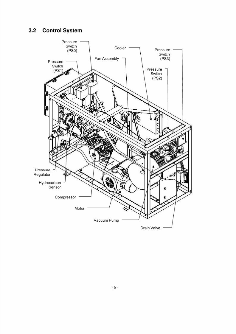
3.2 Control System
Vacuum Pump
Motor
Compressor
HydrocarbonSensor
Pressure
Regulator
PressureSwitch(PS2)
PressureSwitch
(PS3) Fan Assembly
Cooler
PressureSwitch(PS0)
PressureSwitch(PS1)
Drain Valve

8/3/2019 99-50505 Vapor Saver 1 Start-Up and Troubleshooting 2009-04-08
http://slidepdf.com/reader/full/99-50505-vapor-saver-1-start-up-and-troubleshooting-2009-04-08 12/47
- 7 -
Drain Valve
PressureSwitch(PS0)
PressureSwitch(PS1)
Vacuum Pump
Motor
Compressor
PressureSwitch
PS2
Cooler
Pressure
Switch(PS3)

8/3/2019 99-50505 Vapor Saver 1 Start-Up and Troubleshooting 2009-04-08
http://slidepdf.com/reader/full/99-50505-vapor-saver-1-start-up-and-troubleshooting-2009-04-08 13/47
- 8 -
3.3 Operating Pressures and Pressure SettingsTypical internal operating pressures of the system are:
• Compressor (feed) = 30 psig +/- 3 psig (2.1 bar +/- 0.2 bar)o Early systems operate at 25 psig +/- 3 psig (1.7 bar +/- 0.2 bar)
• Vacuum (permeate) = -20 inHg +/- 3 inHg (-0.67 bar +/- 0.1 bar)
PressureSwitch
WireConnections Set Pressure
PS0(A) COM – N/O-1.0 inwc
(-2.5 mbar)
PS1(A) COM – N/O+0.15 inwc
(+0.37 mbar)
PS2(A) COM – N/O8 to 10 psig
(0.55 to 0.69 bar)
PS3(A) COM – N/C-8 to -10 inHg
(-0.27 to -0.34 bar)
8/3/2019 99-50505 Vapor Saver 1 Start-Up and Troubleshooting 2009-04-08
http://slidepdf.com/reader/full/99-50505-vapor-saver-1-start-up-and-troubleshooting-2009-04-08 14/47
- 9 -
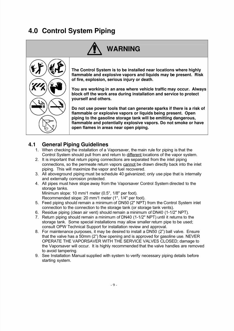
4.0 Control System Piping
WARNING
The Control System is to be installed near locations where highlyflammable and explosive vapors and liquids may be present. Riskof fire, explosion, serious injury or death.
You are working in an area where vehicle traffic may occur. Alwaysblock off the work area during installation and service to protectyourself and others.
Do not use power tools that can generate sparks if there is a risk offlammable or explosive vapors or liquids being present. Openpiping to the gasoline storage tank will be emitting dangerous,flammable and potentially explosive vapors. Do not smoke or haveopen flames in areas near open piping.
4.1 General Piping Guidelines1. When checking the installation of a Vaporsaver, the main rule for piping is that the
Control System should pull from and return to different locations of the vapor system.2. It is important that return piping connections are separated from the inlet piping
connections, so the permeate return vapors cannot be drawn directly back into the inletpiping. This will maximize the vapor and fuel recovered.
3. All aboveground piping must be schedule 40 galvanized; only use pipe that is internallyand externally corrosion protected.
4. All pipes must have slope away from the Vaporsaver Control System directed to thestorage tanks.Minimum slope: 10 mm/1 meter (0.5°, 1/8" per foot).Recommended slope: 20 mm/1 meter (1°, 1/4" per foot).
5. Feed piping should remain a minimum of DN50 (2" NPT) from the Control System inletconnection to the connection to the storage tank (or storage tank vents).
6. Residue piping (clean air vent) should remain a minimum of DN40 (1-1/2" NPT).7. Return piping should remain a minimum of DN40 (1-1/2" NPT) until it returns to the
storage tank. Some special installations may allow smaller return pipe to be used;consult OPW Technical Support for installation review and approval.
8. For maintenance purposes, it may be desired to install a DN50 (2”) ball valve. Ensurethat the valve has a 50mm (2”) flow opening and is approved for gasoline use. NEVEROPERATE THE VAPORSAVER WITH THE SERVICE VALVES CLOSED; damage tothe Vaporsaver will occur. It is highly recommended that the valve handles are removedto avoid tampering.
9. See Installation Manual supplied with system to verify necessary piping details beforestarting system.

8/3/2019 99-50505 Vapor Saver 1 Start-Up and Troubleshooting 2009-04-08
http://slidepdf.com/reader/full/99-50505-vapor-saver-1-start-up-and-troubleshooting-2009-04-08 15/47
- 10 -
5.0 Electrical Requirements
WARNING
OFF
This system uses lethal voltages and operates in areaswhere flammable vapors and liquids may be present.
Serious injury or death from electrical shock, fire, orexplosion may result if the power is on during installation.
Turn power off, lockout and tag power to the unit whileinstalling the system.
Read and understand all instructions in this manual and allapplicable requirements of the National Electric Code,federal, state and local codes and regulations, as well asother all other applicable safety codes.
5.1 Power Requirements
System Type ATEX(00-50003, 00-50004)
UL(00-50001, 00-50002,
00-50006)
KHK(00-50005)
User InterfaceVoltage 100-240 VAC
50/60 Hz100-240 VAC
50/60 Hz100-240 VAC
50/60 Hz
Phase 1 1 1
Amp 0.5 0.5 0.5Control System (motor)
Voltage 380-415 VAC, 50 Hz440-480 VAC, 60 Hz
230 VAC, 50 Hz208-230 VAC, 60 Hz
200 VAC, 50 Hz,200-220 VAC, 60 Hz
Phase 3 1 3
Hp (kW) 1.8 kW 2.4 Hp 2.2 kW
FLA 3.0 amps, 50 Hz2.6 amps, 60 Hz
9.5 amps, 50 Hz9.0-8.3 amps, 60 Hz
8.7 amps, 50 Hz8.4-7.8 amps, 60 Hz
Motor Contactor Coil Voltage(ATEX only)
220-230 VAC, 50 Hz230-240 VAC, 60 Hz
N/A N/A
Coil Voltage(KHK only)
N/A N/A 100-110 VAC, 50 Hz110-120 VAC, 60 Hz
Contact Rating(ATEX and KHK)
230 VAC,3-ph,2.2kW400 VAC,3-ph,4 kW480 VAC,3-ph,5 hp
N/A 230 VAC,3-ph,2.2kW400 VAC,3-ph,4 kW480 VAC,3-ph,5 hp
For ATEX and KHK systems, refer to the specific electrical interconnect drawings in theInstallation Manual that accompanied the system for motor contactor requirements.

8/3/2019 99-50505 Vapor Saver 1 Start-Up and Troubleshooting 2009-04-08
http://slidepdf.com/reader/full/99-50505-vapor-saver-1-start-up-and-troubleshooting-2009-04-08 16/47
- 11 -
1. The User Interface has internal fuse: 500 mA (slow-blow), 250 V, 5mm x 20mm. Thefuse is to only be replaced by qualified and certified technicians. Do not substitute fusefor any other size or rating.
2. Follow all requirements by the national, state, and local, authorities and regulations.3. The Vaporsaver 1 main power should be controlled by the facility’s main Emergency
Shut-Off system.4. SPECIAL NOTE FOR 3-PHASE MOTORS: Ensure that motor rotation is correct the first
time the unit is powered. If the motor rotation is incorrect exchange any two of the 3-phase conductors. If reverse rotation is noted, immediately power off the unit andcorrect wiring. Reverse rotation can cause internal damage to the vacuum pump.
5. SPECIAL NOTE FOR 50/60 Hz OPERATION: Each Control System can be supplied as50 Hz or 60 Hz. Different pulleys are used to compensate for different motor speeds.
5.2 Control System Electrical Hook Ups1. System overload circuit breaker shall be sized for power load based on national and
local requirements.2. Wiring between the User Interface and the Control System shall be as follows.
a. Always follow national and local electrical regulations.
b. All wiring to be gasoline and oil resistant with 600 V insulation.c. Wiring for the 24 VDC control signals shall be minimum 1.0 mm2 (18 AWG).d. Two ground wires shall be run from the Control System junction box to the load
center ground; one is for equipment ground, and the second is for a dedicatedIntrinsically Safe Barrier ground. Both ground wires must be minimum 3.3 mm2 (12 AWG). Proper grounding for the Intrinsically Safe Barrier is crucial for safeoperation of the Barriers.
e. Both the motor power wiring and the signal wiring can be routed in the sameconduit provided all wiring is rated gasoline and oil resistant wiring with 600 Vinsulation.
f. Wiring for motor shall be minimum 3.3 mm2 (12 AWG); sizing must comply withrequirements for motor load and wiring distance. Larger gage wire may be
necessary based on conductor length and voltage supplied by load center.g. Many electrical codes recommend a maximum conductor voltage drop of 3%,
and note that with a conductor voltage drop of 5%, most devices should operatewith acceptable efficiency. It should be noted that with a conductor voltage dropof 5%, motor starting capabilities are reduced, and difficult starting may occur.But, always remember that lower conductor voltage drop is always better for motor starting and operating efficiency; so whenever possible use the 3%conductor voltage drop.

8/3/2019 99-50505 Vapor Saver 1 Start-Up and Troubleshooting 2009-04-08
http://slidepdf.com/reader/full/99-50505-vapor-saver-1-start-up-and-troubleshooting-2009-04-08 17/47
- 12 -
Conductor Length and Size Guide
Maximum conductor length is the total length of the conductor from the load center throughthe User Interface to the motor.
Maximum Conductor Length (1-Phase)Voltage 208 208 230 230
% Voltage Drop 3% 5% 3% 5%
AWG mm2
Feet (meters)
12 3.3 91(28) 151 (46) 100 (30) 167 (51)
10 5.3 144 (44) 240 (73) 159 (48) 265 (81)
8 8.4 229 (70) 382 (116) 254 (77) 423 (129)
Maximum Conductor Length (3-Phase)Voltage 200 200 230 230 400 460
% Voltage Drop 3% 5% 3% 5% 3% 3%
AWG mm2
Feet (meters)14 2.1 506 (154) 671 (205)
12 3.3 139 (42) 231 (70) 178 (54) 297 (91) 805 (245) 1068 (331)
10 5.3 220 (67) 365 (111) 283 (86) 471 (144) 1279 (390) 1697 (517)
8 8.4 351 (107) 585 (178) 450 (137) 751 (229) 2037 (620) 2702 (824)
Notes:
• These tables are based on 140% of nameplate ratings, if national or local authoritywill allow voltage drop conductor length calculations based on load ampacity rating of 125% of motor nameplate, multiply the maximum length in the table by 1.12 to getthe new maximum conductor length.
• For 3-phase voltages over 380 volts, 2.1 mm2 (14 AWG) can be used if:o local electrical regulations allow for it to be used in motor applications and for
the motor ratings stated on the motor name plate, ando the voltage at the motor and the running amps of the motor are within the
limits stated on the motor nameplate, ando motor starting difficulties are not present.
THESE TABLES ARE ONLY TO BE USED AS A REFERENCE.ALWAYS VERIFY AND FOLLOW NATIONAL AND LOCAL ELECTRICAL REGULATIONS.
8/3/2019 99-50505 Vapor Saver 1 Start-Up and Troubleshooting 2009-04-08
http://slidepdf.com/reader/full/99-50505-vapor-saver-1-start-up-and-troubleshooting-2009-04-08 18/47
- 13 -
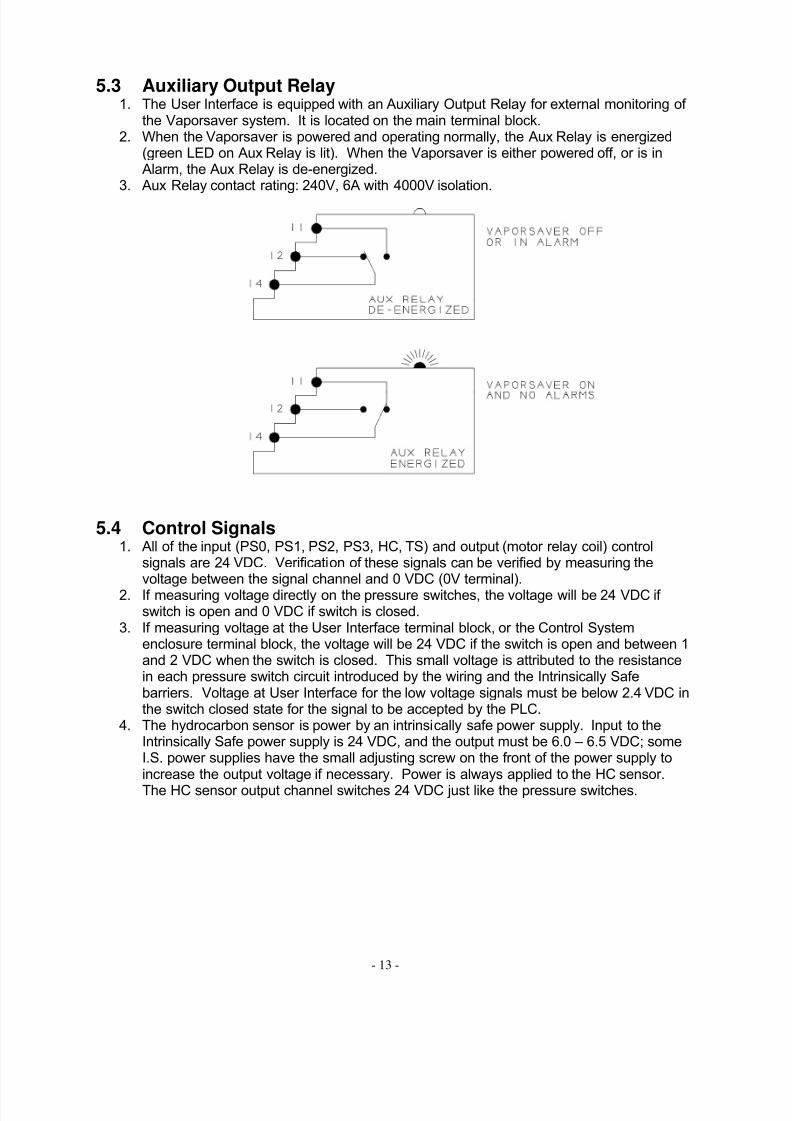
5.3 Auxiliary Output Relay1. The User Interface is equipped with an Auxiliary Output Relay for external monitoring of
the Vaporsaver system. It is located on the main terminal block.2. When the Vaporsaver is powered and operating normally, the Aux Relay is energized
(green LED on Aux Relay is lit). When the Vaporsaver is either powered off, or is inAlarm, the Aux Relay is de-energized.
3. Aux Relay contact rating: 240V, 6A with 4000V isolation.
5.4 Control Signals1. All of the input (PS0, PS1, PS2, PS3, HC, TS) and output (motor relay coil) control
signals are 24 VDC. Verification of these signals can be verified by measuring thevoltage between the signal channel and 0 VDC (0V terminal).
2. If measuring voltage directly on the pressure switches, the voltage will be 24 VDC if switch is open and 0 VDC if switch is closed.
3. If measuring voltage at the User Interface terminal block, or the Control Systemenclosure terminal block, the voltage will be 24 VDC if the switch is open and between 1and 2 VDC when the switch is closed. This small voltage is attributed to the resistancein each pressure switch circuit introduced by the wiring and the Intrinsically Safebarriers. Voltage at User Interface for the low voltage signals must be below 2.4 VDC inthe switch closed state for the signal to be accepted by the PLC.
4. The hydrocarbon sensor is power by an intrinsically safe power supply. Input to theIntrinsically Safe power supply is 24 VDC, and the output must be 6.0 – 6.5 VDC; someI.S. power supplies have the small adjusting screw on the front of the power supply toincrease the output voltage if necessary. Power is always applied to the HC sensor.
The HC sensor output channel switches 24 VDC just like the pressure switches.

8/3/2019 99-50505 Vapor Saver 1 Start-Up and Troubleshooting 2009-04-08
http://slidepdf.com/reader/full/99-50505-vapor-saver-1-start-up-and-troubleshooting-2009-04-08 19/47
- 14 -
5.5 Motor Thermal Overload Switch (TS)1. In the event the motor is failing or the load is too great (failing pumps, over tight belts…),
the motor internal thermal switch can open to protect the motor from damage or anunsafe failure.
2. On UL Systems the TS is electrically in series with the motor relay coil. If the motor overheats, the TS will open, causing the motor relay to de-energize. The PLC willcontinue to have a motor output signal (Y3) until the system goes into COMP and/or VAC Alarms.
3. On ATEX and KHK systems, the motor thermal switch is completely internal to the motor and does not connect to the motor relay coil. Therefore, the TS wire is jumpered to 0Veither at the Control System main electrical enclosure, or in the User Interfaceenclosure.
8/3/2019 99-50505 Vapor Saver 1 Start-Up and Troubleshooting 2009-04-08
http://slidepdf.com/reader/full/99-50505-vapor-saver-1-start-up-and-troubleshooting-2009-04-08 20/47
- 15 -
6.0 User Interface
WARNING
OFF
Rotating machinery. Keep clear of the Control System whenpowering up or resetting the unit. The unit will startautomatically. Be sure all covers are in place when power isapplied to unit, starting or resetting the unit. Risk of seriousinjury.
Always power off system when performing maintenance orservice. Unit starts automatically. Risk of serious injury.
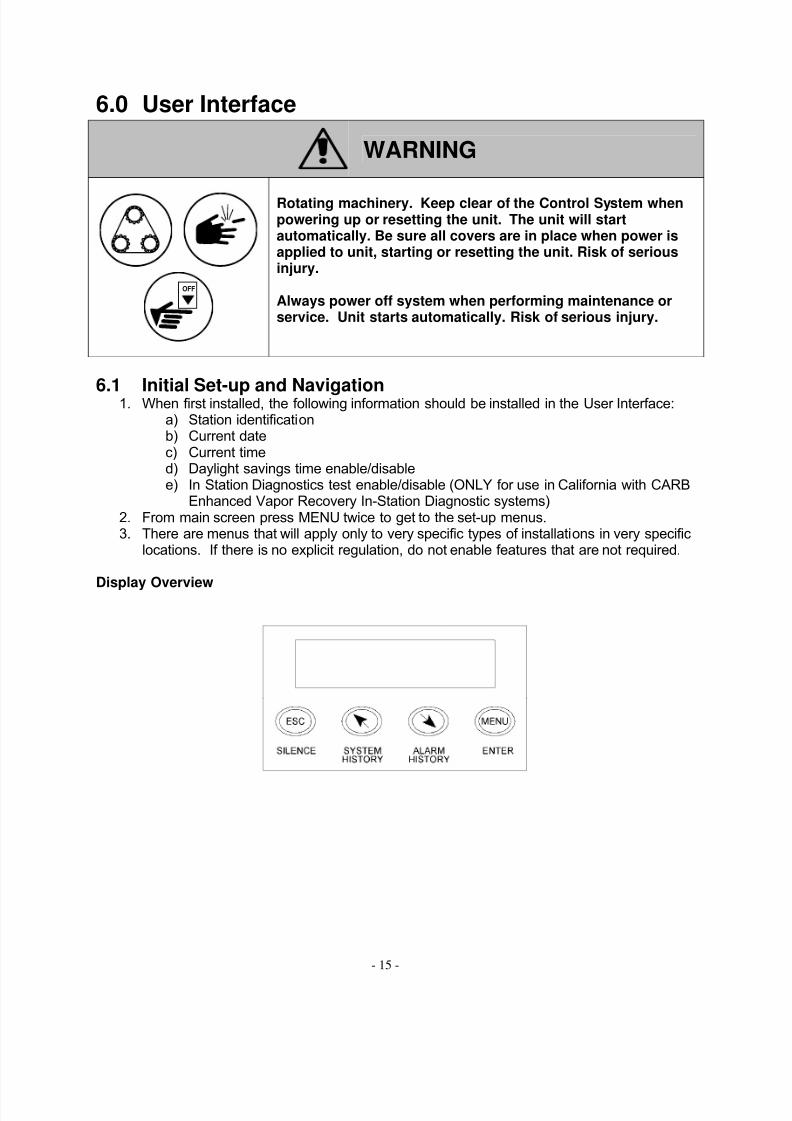
6.1 Initial Set-up and Navigation1. When first installed, the following information should be installed in the User Interface:a) Station identificationb) Current datec) Current timed) Daylight savings time enable/disablee) In Station Diagnostics test enable/disable (ONLY for use in California with CARB
Enhanced Vapor Recovery In-Station Diagnostic systems)2. From main screen press MENU twice to get to the set-up menus.3. There are menus that will apply only to very specific types of installations in very specific
locations. If there is no explicit regulation, do not enable features that are not required.
Display Overview

8/3/2019 99-50505 Vapor Saver 1 Start-Up and Troubleshooting 2009-04-08
http://slidepdf.com/reader/full/99-50505-vapor-saver-1-start-up-and-troubleshooting-2009-04-08 21/47
- 16 -
Initial Set-up Navigation
8/3/2019 99-50505 Vapor Saver 1 Start-Up and Troubleshooting 2009-04-08
http://slidepdf.com/reader/full/99-50505-vapor-saver-1-start-up-and-troubleshooting-2009-04-08 22/47
- 17 -
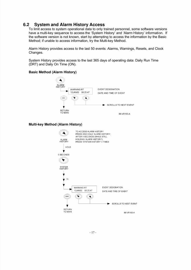
6.2 System and Alarm History AccessTo limit access to system operational data to only trained personnel, some software versionshave a multi-key sequence to access the ‘System History’ and ‘Alarm History’ information. If the software version is not known, start by attempting to access the information by the BasicMethod; if unable to access information, try the Multi-key Method.
Alarm History provides access to the last 50 events: Alarms, Warnings, Resets, and ClockChanges.
System History provides access to the last 365 days of operating data: Daily Run Time(DRT) and Daily On Time (ON).
Basic Method (Alarm History)
Multi-key Method (Alarm History)

8/3/2019 99-50505 Vapor Saver 1 Start-Up and Troubleshooting 2009-04-08
http://slidepdf.com/reader/full/99-50505-vapor-saver-1-start-up-and-troubleshooting-2009-04-08 23/47
- 18 -
Basic Method (System History)
Multi-key Method (System History)

8/3/2019 99-50505 Vapor Saver 1 Start-Up and Troubleshooting 2009-04-08
http://slidepdf.com/reader/full/99-50505-vapor-saver-1-start-up-and-troubleshooting-2009-04-08 24/47
- 19 -
6.3 Start-up/Self-Test1. Each time the power to the Vaporsaver is cycled ON or the system is RESET, it will go
through a Self Test for up to 180 seconds. It will display:
SYSTEM SELF TESTPLEASE WAIT ###
Control System is performing a self diagnostic (display shows timer)
2. During this time, the Control System will run and verify proper operation of all of thecomponents. If there is a problem, the Control System will shut down and the User Interface will sound an alarm and display the alarm condition.
During a self-test, a timer will be shown on the front display. Once the motor relay isenergized, the timer will start. The motor will operate for 120 seconds. Below is the self-testsequence.
Timer Actions
0 Motor starts (motor relay closes)
60 PS2 (X2 on) and PS3 (X3 on) must be closed by timer = 60 seconds andremain closed until motor stops.
60 HC must be closed (X4 on) for at least 10 continuous seconds between self-test timer 60-120 seconds.
120 Motor stops (motor relay opens)120 – 180 PS2 and PS3 must open (X2 and X3 off) within 60 seconds of the motor
deactivation.
If any of the above conditions are not met, the system will alarm and indicate the problemarea.
6.4 Normal OperationOnce the Self Test is successfully completed, the User Interface displays a continuous
scrolling screen showing the following information.
SYSTEM NORMAL Operational StatusDATE TIME Current Date and Time
TRT xxxxxx HRS Total Run Time since installed (hours)DRT xxxx MIN Daily Run Time so far current day (minutes)
6.5 Alarms and Their Causes1. When an error has occurred in the operation of the Control System, the User Interface
will sound a buzzer and the display will change from SYSTEM NORMAL to the
appropriate error code. The station operator should then call for service.2. The alarm buzzer does not indicate a safety emergency. If the Control System is not
functioning properly, an alarm will sound, and the Control System will shut down to asafe mode.
3. The Vaporsaver is equipped with self-test capabilities to minimize false alarms.4. Some local authorities may require notification of the local Air Quality District in the event
of an alarm.5. If more then one alarm occurs at the same time, the most recent will appear first, then
the previous one, until all the current alarms are shown.

8/3/2019 99-50505 Vapor Saver 1 Start-Up and Troubleshooting 2009-04-08
http://slidepdf.com/reader/full/99-50505-vapor-saver-1-start-up-and-troubleshooting-2009-04-08 25/47
- 20 -
Comp Alarm1. During a “System Self Test”, if PS2 is not activated within 60 seconds of the motor
starting.2. During “System Normal” operation, is PS2 is not activated within 60 seconds of the
motor starting on 15 consecutive run cycles.
Vac Alarm1. During a “System Self Test”, if PS3 is not activated within 60 seconds of the motor
starting.2. During “System Normal” operation, is PS3 is not activated within 60 seconds of the
motor starting on 15 consecutive run cycles.
HC Alarm1. During a “System Self Test”, if HC is not activated for 10 continuous seconds between
60 and 120 seconds of the Self Test Timer.2. During “System Normal” operation, if HC is not activated for 60 continuous motor
running minutes.
PR Warning1. During a “System Self Test”, if PS2 and/or PS3 do not open within 60 seconds of the
motor relay opening.2. During “System Normal” operation, if PS2 and/or PS3 do not open within 110 seconds of
the motor relay opening.
RT Warning1. Seven consecutive days of run time greater than 1140 minutes.
Note: Warnings do not shut the System down, but a certified service technician should becalled to investigate the abnormal behavior.
Comm Error or PLC Not Running1. This is a result of the PLC and Display losing communications.2. Generally caused by a failure in the cable between the PLC and the display or
incompatible programs in the PLC and Display.3. Verify “RUN/PROG” switch on PLC is on “RUN”4. Verify green “RUN” LED on PLC is lit.
8/3/2019 99-50505 Vapor Saver 1 Start-Up and Troubleshooting 2009-04-08
http://slidepdf.com/reader/full/99-50505-vapor-saver-1-start-up-and-troubleshooting-2009-04-08 26/47
- 21 -
6.6 Silencing Alarms1. Once an alarm is triggered, the User Interface will emit an audible tone with a visual
indication. This indicates that the Vaporsaver requires immediate attention. Serviceshould be called.
2. Once the alarm has been noted, and the appropriate action has been taken, the alarmSILENCE button can be pushed to silence the alarm.
3. The red alarm indicator will remain flashing until the Vaporsaver is serviced and reset bya trained technician.
6.7 Resetting Alarms1. The alarm should only be reset by factory trained personnel.2. When the System is reset, the Control System will start running. Be sure there are no
people or tools inside or near the unit.3. Press the MENU button.4. Press the RESET button.5. Press the YES button.
6. If the Control System completes the Self Test without any problems, the display willreturn to SYSTEM NORMAL.
8/3/2019 99-50505 Vapor Saver 1 Start-Up and Troubleshooting 2009-04-08
http://slidepdf.com/reader/full/99-50505-vapor-saver-1-start-up-and-troubleshooting-2009-04-08 27/47
- 22 -
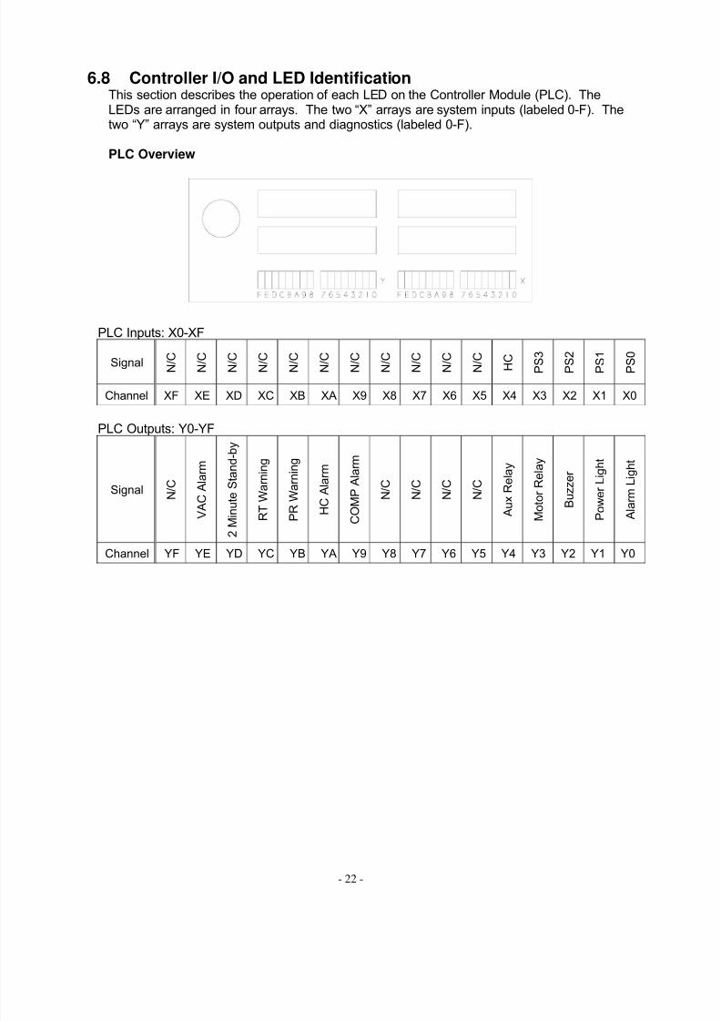
6.8 Controller I/O and LED IdentificationThis section describes the operation of each LED on the Controller Module (PLC). TheLEDs are arranged in four arrays. The two “X” arrays are system inputs (labeled 0-F). Thetwo “Y” arrays are system outputs and diagnostics (labeled 0-F).
PLC Overview
PLC Inputs: X0-XF
Signal N / C N / C N / C N / C N / C N / C N / C N / C N / C N / C N / C H C P S 3 P S 2 P S 1 P S 0
Channel XF XE XD XC XB XA X9 X8 X7 X6 X5 X4 X3 X2 X1 X0
PLC Outputs: Y0-YF
Signal N / C
V A C A l a r m
2
M i n u t e S t a n d - b y
R T W a r n i n g
P R W a r n i n g
H C A l a r m
C O M P A l a r m
N / C
N / C
N / C
N / C
A u x R e l a y
M o t o r R e l a y
B u z z e r
P o w e r L i g h t
A l a r m L i g h t
Channel YF YE YD YC YB YA Y9 Y8 Y7 Y6 Y5 Y4 Y3 Y2 Y1 Y0

8/3/2019 99-50505 Vapor Saver 1 Start-Up and Troubleshooting 2009-04-08
http://slidepdf.com/reader/full/99-50505-vapor-saver-1-start-up-and-troubleshooting-2009-04-08 28/47
- 23 -
LED Operation
LED Signal LED ON LED OFF
X0 PS0 (Stop) PS0 closed PS0 open
X1 PS1 (Run) PS1 closed PS1 open
X2 PS2 (Comp) PS2 closed PS2 open
X3 PS3 (Vac) PS3 closed PS3 open
X4 HC sensor HC sensor low; HC low % HC sensor high; HC high %
X5 - XF N/C
Y0 Alarm Light Alarm light on Alarm light off
Y1 Power Light Power light on Power light off
Y2 Buzzer Buzzer on Buzzer off
Y3 Motor Relay Motor relay energized Motor relay not energized
Y4 Aux Relay System Normal Loss of power or Alarm
Y5 – Y8 N/C
Y9 Comp Alarm COMP Alarm System Normal
YA HC Alarm HC Alarm System Normal
YB PR Warn PR Warning System Normal
YC RT Warn RT Warning System Normal
YD Standby 2 minute standby active System Normal
YE Vac Alarm VAC Alarm System Normal
YF N/C
6.9 Communications
1. The Vaporsaver User Interface has a DB9 serial communications port located on the leftside of the enclosure. This can be use to download the System History and AlarmHistory reports to a computer using any standard terminal emulation program (e.g.HyperTerminal or Procomm).
2. Local Communications Settings:a. Data bits: 8b. Parity: nonec. Stop bits: 1d. Flow Control: Xon/Xoff (software flow control)e. Max speed: 9600 bps
3. Report Download:a. Once communications are successfully established, press the ESC key and a
COMMAND prompt will appear.b. All communication commands must be entered in ALL CAPS (followed byENTER).
c. Enter report download command; there are different commands depending onthe software version (note: if software version is not known, try one command,and if no data is downloaded, try other command.
o MRH (motor run history)o SD (send data)

8/3/2019 99-50505 Vapor Saver 1 Start-Up and Troubleshooting 2009-04-08
http://slidepdf.com/reader/full/99-50505-vapor-saver-1-start-up-and-troubleshooting-2009-04-08 29/47
- 24 -
Example Report
Station header information
Date and time of report generation
System Total Run Time (hours)
Last 365 day of the following:
Date, System ON time, and Daily Run Time (minutes)
Last 50 Events (Alarms, Resets, and Clock changes)
Date and Time of Event, and Event designation
Date/time: ddmmmyy hh:mm:ss
EL DORADO HILL761020 SARATOGAWAYELDORADOHILLS,CA916-555-1234
18SEP02 05:48:46
TRT 545
SYSTEM HISTORYDATE ON DRT18SEP02 349 517SEP02 1440 13316SEP02 1440 14615SEP02 1440 15414SEP02 1440 30213SEP02 1440 117
ALARM HISTORYDATE EVENT09SEP02 13:44:17 RESET
09SEP02 12:09:33 COMP06SEP02 13:09:50 RESET06SEP02 13:06:58 VAC06SEP02 11:43:16 RESET06SEP02 11:30:11 CLOCK

8/3/2019 99-50505 Vapor Saver 1 Start-Up and Troubleshooting 2009-04-08
http://slidepdf.com/reader/full/99-50505-vapor-saver-1-start-up-and-troubleshooting-2009-04-08 30/47
- 25 -
7.0 Control System Trouble Shooting
OFF
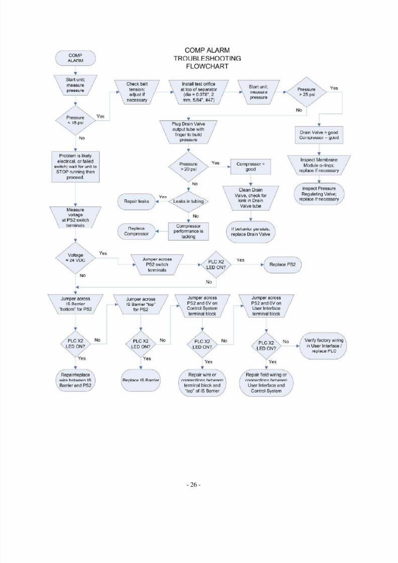
7.1 COMP ALARM (Compressor Alarm)Compressor pressure is not sensed within the allowable time. Use pressure tap (1/4” NPT)on top of separator to install test gage (0-50 PSI or 4 bar) and measure feed pressure.
COMP AlarmPotential Alarm Cause Action ResultMotor service switch OFF Verify switch and voltage Turn switch ON, reset
system
Drive belt loose andslipping
Visual Inspection of belttension
Adjust idler (15-20 degrees)
Drive belt failure Visual Inspection Replace belt
Compressor pump failure Pump shaft not turning;Extreme belt wear
Replace pump
Drive motor failure Motor not spinning withpower applied
Check wiring, Replacerelay, replace motor
Control System not holdingpressure
Separator drainvalve not closing
Drain valve outlet hassignificant flow whengreater than 5 psi
Disassemble, inspect, andclean, replace drain valve.
Leaks in ControlSystem piping
None of the above obviouson visual inspection
Inspect at all tube and pipe joints and tighten; use soapbubble or leak detectionsolution to inspect all tubeand pipe joints
Failure of pressure switch(PS2); failure of I.S. module
A good switch and circuitwill show: when closed,approx 0 VDC acrosscontacts; when openapprox 24 VDC across
contacts. Measure atswitch, I.S. terminal block,and User Interface
Check wiringCheck and replace switchCheck and replace I.S.module
Damaged o-ring onmembrane module or housing flange
Inspect o-rings onmembrane module
Replace damaged o-rings
8/3/2019 99-50505 Vapor Saver 1 Start-Up and Troubleshooting 2009-04-08
http://slidepdf.com/reader/full/99-50505-vapor-saver-1-start-up-and-troubleshooting-2009-04-08 31/47
- 26 -

8/3/2019 99-50505 Vapor Saver 1 Start-Up and Troubleshooting 2009-04-08
http://slidepdf.com/reader/full/99-50505-vapor-saver-1-start-up-and-troubleshooting-2009-04-08 32/47
- 27 -
Testing NotesThis section describes one means and the necessary tools to isolate and test a compressor that is installed in a Vaporsaver control system. These tests are to aid in diagnosingcompressor related alarms to either verify a compressor failure, or prove the state of a goodcompressor. All tests described should only be performed for short periods.
CAUTION: during these tests, gasoline vapors may be emitted; always use caution around
gasoline vapors; be sure that there are no near by ignition sources before performing thesetests. NEVER test when in violation of local regulations. If tubing is removed duringtesting, ALWAYS be sure that all tubing in reinstalled and fittings are tight beforerestarting unit.
NOTE: for these compressor tests, it is required to disconnect the compressor inlet from thegasoline storage tank so the compressor is only pumping air; pumping gasoline vapor maycreate a safety hazard as well as affecting the readings because of the difference in densityof air and gasoline vapor; testing on air will ensure consistent results.
To make a Test Orifice, use Parker 5/8” SAE 45° flare cap p/n 640F-10 and drill orificethrough top of cap (0.078 inch, 2.0 mm, 5/64 inch, #47).
To plug Drain Valve tube,carefully disconnect tubefrom this compression fitting.It is very important to notdamage or deform the tubeor fitting as a leak or reduction in performancemay occur.
Test Orifice:Remove tube from topof separator andinstall the Test Orificeonto the separator flare fitting.
During Orifice Test, disconnectthe compressor inlet tube so thecompressor is only pumping air and not vapor from the tank.

8/3/2019 99-50505 Vapor Saver 1 Start-Up and Troubleshooting 2009-04-08
http://slidepdf.com/reader/full/99-50505-vapor-saver-1-start-up-and-troubleshooting-2009-04-08 33/47
- 28 -
CAUTION: during these tests, gasoline vapors may be emitted; always use caution aroundgasoline vapors; be sure that there are no near by ignition sources before performing thesetests. NEVER test when in violation of local regulations. If tubing is removed duringtesting, ALWAYS be sure that all tubing in reinstalled and fittings are tight beforerestarting unit.
Test Orifice:Remove tube from topof separator andinstall the Test Orificeonto the separator flare fitting.
To move the tube outof the way, it may benecessary to slightlyloosen this tube end.

8/3/2019 99-50505 Vapor Saver 1 Start-Up and Troubleshooting 2009-04-08
http://slidepdf.com/reader/full/99-50505-vapor-saver-1-start-up-and-troubleshooting-2009-04-08 34/47
- 29 -
7.2 VAC ALARM (Vacuum Pump Alarm)PS3 pressure switch does not close on three consecutive run cycles. Use pressure tap (1/4”NPT) on vacuum pump to install test gage (0-30 inHg or 0 to -1 bar) and measure vacuum.
VAC AlarmPotential Alarm Cause Action ResultMotor service switch OFF Verify switch and voltage Turn switch ON, reset
system
Drive belt loose andslipping
Visual Inspection of belttension
Adjust idler (15-20 degrees)
Drive belt failure Visual Inspection; Belt tornor worn
Replace belt
Vacuum pump failure Pump shaft not turning;Extreme belt wear
Replace vanes or pump
Drive motor failure Motor not spinning withpower applied
Replace motor
Control System not holdingvacuum
Leaks in ControlSystem piping
None of the above obviouson visual inspection
Inspect at all tube and pipe joints and tighten
Failure of vacuum switch(PS3); failure of I.S. module
A good switch and circuitwill show: when closedapprox 0 VDC acrosscontacts; when openapprox 24 VDC acrosscontacts. Measure atswitch, I.S. terminal block,
and User Interface
Check and replace switchCheck wiringCheck and replace I.S.module
Damaged o-ring onmembrane module or housing flange
Inspect o-rings onmembrane module
Replace damaged o-rings

8/3/2019 99-50505 Vapor Saver 1 Start-Up and Troubleshooting 2009-04-08
http://slidepdf.com/reader/full/99-50505-vapor-saver-1-start-up-and-troubleshooting-2009-04-08 35/47
- 30 -
8/3/2019 99-50505 Vapor Saver 1 Start-Up and Troubleshooting 2009-04-08
http://slidepdf.com/reader/full/99-50505-vapor-saver-1-start-up-and-troubleshooting-2009-04-08 36/47
- 31 -
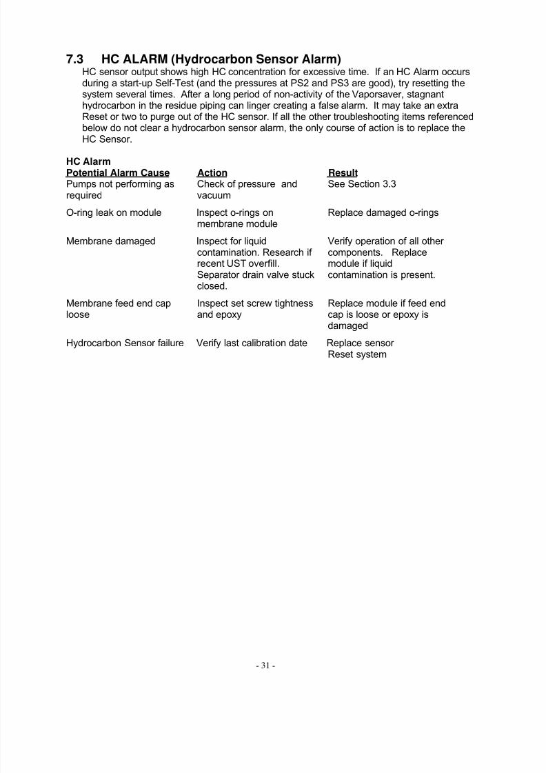
7.3 HC ALARM (Hydrocarbon Sensor Alarm)HC sensor output shows high HC concentration for excessive time. If an HC Alarm occursduring a start-up Self-Test (and the pressures at PS2 and PS3 are good), try resetting thesystem several times. After a long period of non-activity of the Vaporsaver, stagnanthydrocarbon in the residue piping can linger creating a false alarm. It may take an extraReset or two to purge out of the HC sensor. If all the other troubleshooting items referencedbelow do not clear a hydrocarbon sensor alarm, the only course of action is to replace theHC Sensor.
HC AlarmPotential Alarm Cause Action ResultPumps not performing asrequired
Check of pressure andvacuum
See Section 3.3
O-ring leak on module Inspect o-rings onmembrane module
Replace damaged o-rings
Membrane damaged Inspect for liquidcontamination. Research if recent UST overfill.Separator drain valve stuckclosed.
Verify operation of all other components. Replacemodule if liquidcontamination is present.
Membrane feed end caploose
Inspect set screw tightnessand epoxy
Replace module if feed endcap is loose or epoxy isdamaged
Hydrocarbon Sensor failure Verify last calibration date Replace sensor Reset system

8/3/2019 99-50505 Vapor Saver 1 Start-Up and Troubleshooting 2009-04-08
http://slidepdf.com/reader/full/99-50505-vapor-saver-1-start-up-and-troubleshooting-2009-04-08 37/47
- 32 -

8/3/2019 99-50505 Vapor Saver 1 Start-Up and Troubleshooting 2009-04-08
http://slidepdf.com/reader/full/99-50505-vapor-saver-1-start-up-and-troubleshooting-2009-04-08 38/47
- 33 -
7.4 PR WARNINGPS2 and/or PS3 pressure switches have not reset (open) at the end of a run cycle. Thiswarning is not a system shutdown.
Potential Alarm Cause Action ResultThe motor relay has failedclosed
Motor running continuously Check and replace motor relay
Compressor pressureswitch has failed closed
A good switch and circuitwill show: when closed,approx 0 VDC acrosscontacts; when openapprox 24 VDC acrosscontacts. Measure atswitch, I.S. terminal block,and User Interface
Check and replace switchCheck wiringCheck and replace I.S.module
Vacuum switch has failedclosed
A good switch and circuitwill show: when closedapprox 0 VDC acrosscontacts; when openapprox 24 VDC acrosscontacts. Measure atswitch, I.S. terminal block,and User Interface
Check and replace switchCheck wiringCheck and replace I.S.module

8/3/2019 99-50505 Vapor Saver 1 Start-Up and Troubleshooting 2009-04-08
http://slidepdf.com/reader/full/99-50505-vapor-saver-1-start-up-and-troubleshooting-2009-04-08 39/47
- 34 -
7.5 RT WARNINGThis is caused by excessive run time. This warning is not a system shutdown. It is typicallyan indication to the station operator that the vapor space at the facility is extremely leaky or the A/L are improperly set.
Potential Alarm Cause Action ResultExcessive leaks in thefacilities vapor piping
Verify facilities vapor tightness
Repair vapor leaks in thevapor piping and Stage Iand Stage II fittings
A/L outside certified range Verify A/L on all hose points Repair/reset Stage IIsystem components
Pressure switch failure(PS1)(PS0)
A good switch and circuitwill show: when closedapprox 0 VDC acrosscontacts; when open 24VDC across contacts.
Measure at switch, I.S.terminal block, and User Interface
Check and replace switchCheck wiringCheck and replace I.S.module
7.6 PLC ErrorIf the red ERROR LED on the PLC is lit, this typically means that the PLC has a clock error.The normal solution is to set the clock from the User Interface and cycle the power to theunit. The software has a clock recovery routine that will typically clear the PLC error. If thisdoes not resolve the PLC error, it may be necessary to replace the PLC.

8/3/2019 99-50505 Vapor Saver 1 Start-Up and Troubleshooting 2009-04-08
http://slidepdf.com/reader/full/99-50505-vapor-saver-1-start-up-and-troubleshooting-2009-04-08 40/47
- 35 -
8.0 Control System MaintenanceThe OPW Vaporsaver is designed to require very little scheduled maintenance. The followingtable is a general guide of what is required.
8.1 Recommended Maintenance1. Every 36 months, the Hydrocarbon Sensor must be returned to OPW for calibration.
There are no serviceable parts in the Hydrocarbon Sensor. The calibration of theSensor can be verified by checking at two locations:
a. The Hydrocarbon Sensor has a calibration label showing the calibration duedate. Remove the Control System covers to access the Sensor.
b. A second calibration label may be located on the side of the User Interfaceenclosure or Control System electrical enclosure. Also, when a Sensor isreplaced in the field, the replacement sensor is supplied with a new calibrationlabel on the Sensor and a second label to be placed by the installer on the User Interface enclosure or Control System electrical enclosure.
2. Every 12 months, inspect all belts for wear and proper tension. Only replace belts withsame size and type as originally installed.
2. Every 12 months, check Control System operating pressure and vacuum readings.3. Every 12 months, visually check the Control System for overall wear issues.4. Every 12 months check total run time (TRT). If approaching or greater than the
maximum hours stated in Section 8.4 replace pumps. Verify service records to ensurepumps have not already been changed.
8.2 Repair and Maintenance IntervalThe OPW Vaporsaver is designed to require very little scheduled maintenance. Thefollowing table is a general guide of what is required. Please keep in mind that in mostapplications a single Vaporsaver manages the tank pressure for the entire site. In somecases the Vaporsaver is the station's vehicle of compliance to ORVR and EVR regulations.Repair and maintenance of the Vaporsaver, like all equipment, is inevitable. To ensure end-
users can enjoy the benefits of the Vaporsaver's operation, whether in terms of complianceor for the quantifiable savings of fuel due to eliminated vapor emissions, all precautions tominimize down time must be taken. OPW recommends that the Vaporsaver have anallowable repair and maintenance interval not to exceed 72 hours. The allowable interval for your market may vary. OPW products should be used in compliance with applicable federal,state, provincial, and local laws and regulations. The 72-hour interval was arrived at usingthe following worst-case scenario:
1. Alarm sounds at station, contractor dispatched2. Contractor arrives at site, Vaporsaver diagnosed, part unavailable locally3. OPW Cincinnati ships part via Next Day Air on a Saturday4. Sunday part in route5. Monday part received by contractor, repair completed
OPW has many parts stocking distributors so the scenario above, though possible, shouldbe the exception and not the rule. It’s also important to note that should a Vaporsaver shutdown for any reason the facility will default back to the PV vent valve managing tankpressures, exactly how many sites throughout the world operate today.
In California, repair and maintenance intervals are subject to the interpretation of local Air Quality Management Districts (AQMD). Please contact your local AQMD for guidance inyour specific District.
8/3/2019 99-50505 Vapor Saver 1 Start-Up and Troubleshooting 2009-04-08
http://slidepdf.com/reader/full/99-50505-vapor-saver-1-start-up-and-troubleshooting-2009-04-08 41/47
- 36 -
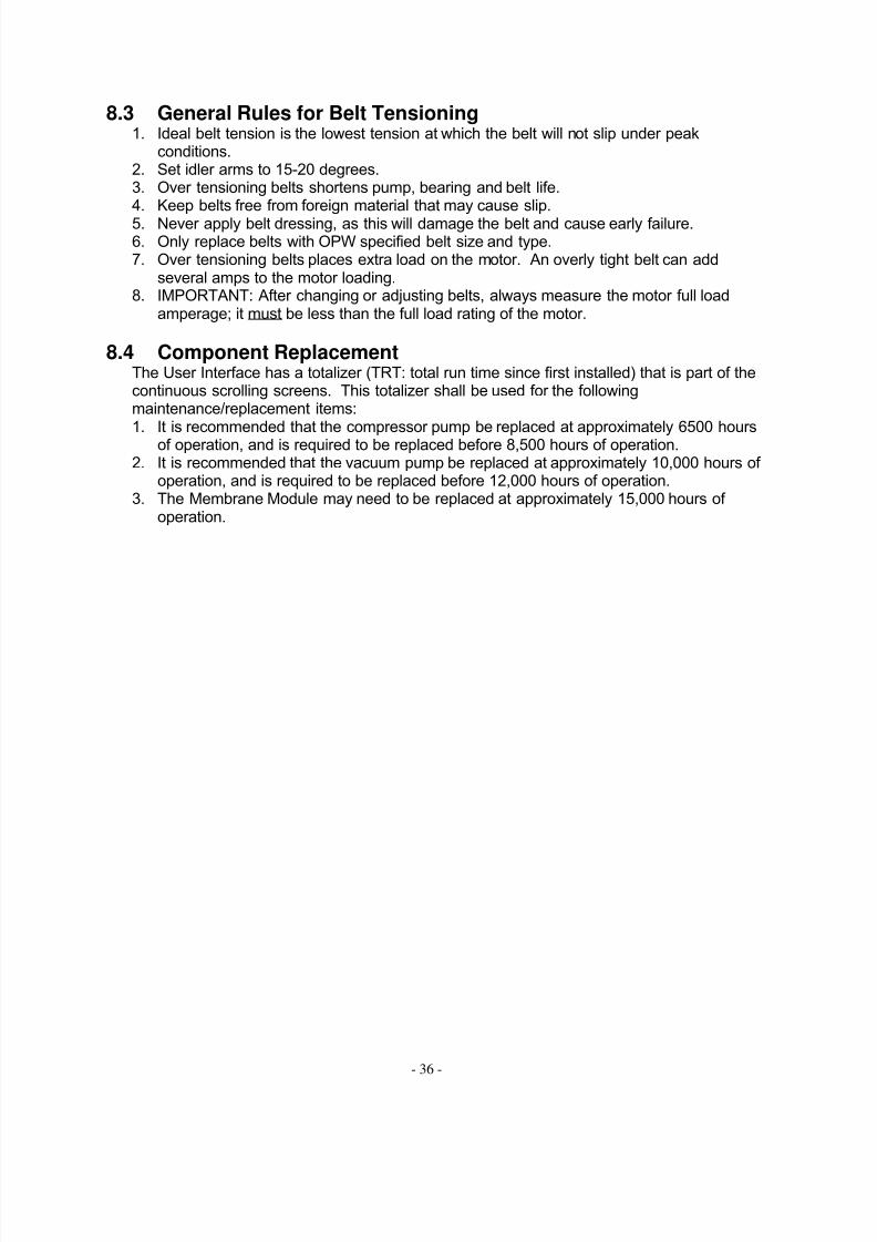
8.3 General Rules for Belt Tensioning1. Ideal belt tension is the lowest tension at which the belt will not slip under peak
conditions.2. Set idler arms to 15-20 degrees.3. Over tensioning belts shortens pump, bearing and belt life.4. Keep belts free from foreign material that may cause slip.5. Never apply belt dressing, as this will damage the belt and cause early failure.6. Only replace belts with OPW specified belt size and type.7. Over tensioning belts places extra load on the motor. An overly tight belt can add
several amps to the motor loading.8. IMPORTANT: After changing or adjusting belts, always measure the motor full load
amperage; it must be less than the full load rating of the motor.
8.4 Component ReplacementThe User Interface has a totalizer (TRT: total run time since first installed) that is part of thecontinuous scrolling screens. This totalizer shall be used for the followingmaintenance/replacement items:
1. It is recommended that the compressor pump be replaced at approximately 6500 hoursof operation, and is required to be replaced before 8,500 hours of operation.2. It is recommended that the vacuum pump be replaced at approximately 10,000 hours of
operation, and is required to be replaced before 12,000 hours of operation.3. The Membrane Module may need to be replaced at approximately 15,000 hours of
operation.
8/3/2019 99-50505 Vapor Saver 1 Start-Up and Troubleshooting 2009-04-08
http://slidepdf.com/reader/full/99-50505-vapor-saver-1-start-up-and-troubleshooting-2009-04-08 42/47
- 37 -
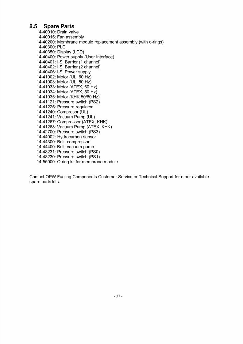
8.5 Spare Parts14-40010: Drain valve14-40015: Fan assembly14-40200: Membrane module replacement assembly (with o-rings)14-40300: PLC14-40350: Display (LCD)14-40400: Power supply (User Interface)14-40401: I.S. Barrier (1 channel)14-40402: I.S. Barrier (2 channel)14-40406: I.S. Power supply14-41002: Motor (UL, 60 Hz)14-41003: Motor (UL, 50 Hz)14-41033: Motor (ATEX, 60 Hz)14-41034: Motor (ATEX, 50 Hz)14-41035: Motor (KHK 50/60 Hz)14-41121: Pressure switch (PS2)14-41225: Pressure regulator 14-41240: Compresor (UL)14-41241: Vacuum Pump (UL)
14-41267: Compressor (ATEX, KHK)14-41268: Vacuum Pump (ATEX, KHK)14-42700: Pressure switch (PS3)14-44002: Hydrocarbon sensor 14-44300: Belt, compressor 14-44400: Belt, vacuum pump14-48231: Pressure switch (PS0)14-48230: Pressure switch (PS1)14-55000: O-ring kit for membrane module
Contact OPW Fueling Components Customer Service or Technical Support for other available
spare parts kits.

8/3/2019 99-50505 Vapor Saver 1 Start-Up and Troubleshooting 2009-04-08
http://slidepdf.com/reader/full/99-50505-vapor-saver-1-start-up-and-troubleshooting-2009-04-08 43/47
- 38 -
9.0 Testing Requirements1. OPW requires that all tests listed in this section be completed to ensure that the facility
meets all the necessary requirements for proper operation on the Vaporsaver.2. All tests referenced in this document are to the current revisions of the approved
procedures in California. Other states or countries may require the use of alternate
approved methods. Always verify with the local authority having jurisdiction theapplicability of CARB or other approved test methods.
3. To ensure proper operation of all vapor recovery components and systems (including theVaporsaver) the entire vapor system (piping, tanks, valves, dispensers…) at a minimummust be able to pass:
a. Pressure Decay (CARB TP-201.3)b. Tie Tank (CARB TP-201.3C)c. Dynamic Back Pressure (CARB TP-201.4)d. A/L (CARB TP-201.5)e. Always follow local authority requirements
4. During Pressure Decay Test (CARB TP-201.3), the Vaporsaver must be powered off.5. During Tie Tank Test (CARB TP-201.3C), the Vaporsaver must be powered off.
6. During Dynamic Back Pressure Test (CARB TP-201.4), the Vaporsaver must bepowered off. The Vaporsaver should not be used with any flexible vapor or vent piping.
7. During Air/Liquid (A/L) ratio testing, the Vaporsaver can be either on or off, as it has noimpact on the testing. Typically the Vaporsaver is left powered to help in controlling thevapor growth associated with air ingestion and liquid return during A/L testing.
8. Other testing may be required by the local authority for other vapor system components,systems, or sub-systems:
a. During Leak Rate of Drop Tube and Drain Valve Assembly Test (CARB TP-201.1C), the Vaporsaver can be either on or off, as it has no impact on thetesting. Typically the Vaporsaver is left powered to continue controlling storagetank pressure.
b. During Leak Rate of Drop Tube Overfill Prevention Devices and Spill Container
Drain Valves Test (CARB TP-201.1D), the Vaporsaver must be powered off.c. During Leak Rate and Cracking Pressure of Pressure/Vacuum Vent Valves Test(CARB TP-201.1E), since the pressure/vacuum vent valve is removed from thevapor system, the Vaporsaver must be powered off.
d. During Static Torque Test (CARB TP-201.1B), the Vaporsaver can be either onor off, as it has not impact on the testing.

8/3/2019 99-50505 Vapor Saver 1 Start-Up and Troubleshooting 2009-04-08
http://slidepdf.com/reader/full/99-50505-vapor-saver-1-start-up-and-troubleshooting-2009-04-08 44/47
Vaporsaver 1
Start-up InformationThis form must be completed and submitted to and approved by OPW for activation of Warranty. Submit form toOPW Technical Services.
OPW Customer Service / Technical Services9393 Princeton-Glendale RoadHamilton, OH 45011Fax: 800-421-3297
STATION INFORMATION:
Station Name and Number:
Street Address:
City:
State or Province: Zip Code: Country:
Station Phone:
Station Fax:
Contact at Station:
PURCHASING / INSTALLATION INFORMATION:
Distributor:
Installation Company:
Address:
City:
State or Province: Zip Code: Country:
Job Site Supervisor:
Installation Certification #:
Installation Date:

8/3/2019 99-50505 Vapor Saver 1 Start-Up and Troubleshooting 2009-04-08
http://slidepdf.com/reader/full/99-50505-vapor-saver-1-start-up-and-troubleshooting-2009-04-08 45/47
Vaporsaver 1
START-UP INFORMATION:
Start-up Company:
Address:
City:
State or Province: Zip Code: Country:
Start-up Technician:
Start-up Certification #:
Start-up Date:
EQUIPMENT INFORMATION:
User Interface Serial Number:
Control System Serial Number:
Wire Gage between Breaker and Control System:
Wire Length between Breaker and Control System:
Quantity Pressure/Vacuum Ratings
Pressure/Vacuum Vent Valves:
Storage Tank Over Fill Prevention Type:(i.e. overfill valve, ball floats, audible alarm)
EQUIPMENT OPERATION:
Volts AmpsMeasured at User
Interface (L1 and L2):
Volts Amps
Measured at ControlSystem (T1 and T2):

8/3/2019 99-50505 Vapor Saver 1 Start-Up and Troubleshooting 2009-04-08
http://slidepdf.com/reader/full/99-50505-vapor-saver-1-start-up-and-troubleshooting-2009-04-08 46/47
Vaporsaver 1
START-UP CHECK LIST:
Y/N: Clock is Set on User Interface
Station Information is set in User Interface
ISD Test Enabled (Only if Part of CARB Certified Phase II EVR System)
Daylight Savings Enabled
Control System starts when storage tank has pressure has reached PS1 set point
Control System stops when storage tank has pressure reached PS0 set point
Piping slope between Control System and vents meets requirements (1/4” per foot)
Electrical insulation test performed (Megometer)
NPT conversion fittings (if applicable for international installations)
Galvanized or corrosion protected piping (internal and external corrosion protection)
All wiring connections verified on User Interface and Control System
Control System protection (vehicle bumper posts, fences…)

8/3/2019 99-50505 Vapor Saver 1 Start-Up and Troubleshooting 2009-04-08
http://slidepdf.com/reader/full/99-50505-vapor-saver-1-start-up-and-troubleshooting-2009-04-08 47/47
Vaporsaver 1
Submit results of the following tests:
CARB TP-201.3: Determination of 2 Inch WC Static Pressure Performance of Vapor Recovery Systems of Dispensing Facilities
CARB TP-201.3C: Determination of Vapor Piping Connections to Underground Gasoline Storage Tanks (Tie-TankTest)
CARB TP-201.4: Dynamic Back Pressure
Exhibit 5 of the latest applicable CARB Executive Order: Determination (by Volume Meter) of Air to Liquid VolumeRatio of Vapor Recovery Systems of Dispensing Facilities
Note: The above tests can be the same tests that are performed as part of local regulation orpermit conditions. Tests do not need to be repeated. The above tests do not need to becompleted during the actual Vaporsaver start-up, but can be complete before or after inconjunction with the testing required by the local authority. Results of these tests must besupplied to OPW Technical Services Department. Some states may require the use of alternateapproved methods. Always verify with the local authority having jurisdiction the applicability ofCARB or other approved test methods.
Site Layout Diagram: