
99 -05 MAZDA MIATA BASE SUPERCHARGER KIT - 949 … · Rev: 6-09 Technical Support Page 3...
22
Rev: 6-09 Technical Support Page 1 [email protected] or 951-808-9888x4 99-05 MAZDA MIATA BASE SUPERCHARGER KIT INSTALLATION INSTRUCTIONS Part # 888-118: 01-05 Mazda Miata Base (5psi) Supercharger Kit CARB E.O. # Pending The KraftWerks Mazda Miata Supercharger kit is designed and engineered to install with ease. If you are a competent mechanic with a good set of tools the installation will be relatively simple. This is a general installation guide for the KraftWerks Mazda Miata kit however each installation may vary slightly. Please keep these key factors in mind before installing: Please review the entire installation guide before attempting install. If you have any questions about your ability to perform this installation, we recommend you take your vehicle to a performance shop for installation You will be doing a minimal amount of work under the car during this installation. If you do not have a workshop with lifts, you will need a good floor jack and secure jack stands. These jack stands will need to raise the car up enough so that you can get yourself under the chassis. Never work under a car without secure jack stands to support the vehicle.
Transcript of 99 -05 MAZDA MIATA BASE SUPERCHARGER KIT - 949 … · Rev: 6-09 Technical Support Page 3...

Rev: 6-09 Technical Support Page 1 [email protected] or 951-808-9888x4
99-05 MAZDA MIATA BASE SUPERCHARGER KIT INSTALLATION INSTRUCTIONS
Part # 888-118: 01-05 Mazda Miata Base (5psi) Supercharger Kit
CARB E.O. # Pending
The KraftWerks Mazda Miata Supercharger kit is designed and engineered to install with ease. If you
are a competent mechanic with a good set of tools the installation will be relatively simple. This is a
general installation guide for the KraftWerks Mazda Miata kit however each installation may vary
slightly. Please keep these key factors in mind before installing:
Please review the entire installation guide before attempting install. If you have any questions
about your ability to perform this installation, we recommend you take your vehicle to a
performance shop for installation
You will be doing a minimal amount of work under the car during this installation. If you do not
have a workshop with lifts, you will need a good floor jack and secure jack stands. These jack
stands will need to raise the car up enough so that you can get yourself under the chassis. Never
work under a car without secure jack stands to support the vehicle.

Rev: 6-09 Technical Support Page 2 [email protected] or 951-808-9888x4
99-05 MAZDA MIATA BASE SUPERCHARGER KIT INSTALLATION INSTRUCTIONS
For tools you will need:
o A full set of metric wrenches from 8mm to 21mm
o A full set of metric sockets from 8mm to 21mm
o A screwdriver set
o A set of metric allen wrenches
o Wire Crimping Pliers
o Heat Gun or Butane Lighter
o Electrical Tape
All of the tools required for this installation can be purchased at a local hardware or auto parts
store.
Always wear safety glasses when working on your vehicle and work in a well-ventilated area.
If you have not changed your oil and filter recently, this will be a good time to do so. High
quality synthetic oil would be a good choice considering how much additional horsepower your
engine will now be producing. For cold weather we recommend 5w-20 or 30 depending on how
cold your climate is. In warmer weather we recommend 10w-30 or 20w-50 for extreme
temperatures.
Make sure that your vehicle has premium gasoline in the tank (91 Octane or more). Run several
tanks of Premium fuel through your car prior to installing the supercharger to ensure that there is
good Premium grade fuel throughout the system. If you are using a discount brand of fuel, we
suggest you switch to a “top tier” gasoline.
If you have more than 10,000 miles on your spark plugs, we recommend changing them. We
suggest cooler spark plugs. Talk to your KraftWerks representative about the recommended
spark plugs for your application.
If your car is equipped with a replaceable fuel filter with over 50,000 miles on it, we recommend
a new fuel filter. This is critical as proper fuel flow to your newly supercharged engine is of the
utmost importance.
If your car is over 5 years old or has more than 70,000 miles on it, we highly recommend
sending your fuel injectors to RC Engineering for cleaning and flow balancing. It is a reasonable
cost to have this service performed and it is good insurance. We have had several sets of our
own injectors cleaned and flowed and without exception one or more of the injectors was not
flowing correctly or they had a poor spray pattern.
If your car has more than 100,000 miles, you should consider installing a new stock radiator or a
high performance aluminum radiator and thermostat. High calcium content water can leave your
radiator with large calcium deposits over time that you would not normally be aware of. But
once you start producing large amounts of power from your newly supercharged engine your old
calcified radiator will not cool enough and your coolant temperatures will be elevated.

Rev: 6-09 Technical Support Page 3 [email protected] or 951-808-9888x4
99-05 MAZDA MIATA BASE SUPERCHARGER KIT INSTALLATION INSTRUCTIONS
Vehicle maintenance is important for the life of your car, engine, and supercharger system. If
your vehicle has been well-maintained, you should have no additional maintenance with the
KraftWerks supercharger system. A well maintained engine in good condition will see little
reduction in useful life with the KraftWerks supercharger system.
You should always allow your engine to reach proper operating temperature before using full
boost.
The KraftWerks Miata system is not compatible with the strut tower braces.
If you are using an aftermarket header or test pipe, it may cause the fuel calibration to go out of
specification. This Supercharger Kit and the SuperCard Fuel Management were designed to be
reliable and emissions compliant when used with the stock exhaust header and catalytic
converter. If you plan on using a header or test pipe, it is recommended that you have your car
dyno tested to verify the air fuel ratio is still safe.
Please contact your KraftWerks representative about authorized upgrades to your KraftWerks
supercharger system. For the best performance and reliability only install authorized upgrades
on your KraftWerks supercharger system.
Rev: 6-09 Technical Support Page 4 [email protected] or 951-808-9888x4
99-05 MAZDA MIATA BASE SUPERCHARGER KIT INSTALLATION INSTRUCTIONS
For the optimal engine cooling, we recommend the KraftWerks Miata Coolant Re-Route kit. The Miata
was designed to be a great car in stock form and gives the owner a pleasant experience in both hot and
cold weather conditions. In stock form the coolant is pumped through the engine from the bottom of the
radiator. This coolant then travels out of the front of the cylinder head and back to the radiator. An
additional coolant hose takes hot coolant off the back of the cylinder head and routes it through your
heater core. From the heater core it travels back to the intake of the water pump. In this way your
interior heater warms up quickly in cold weather conditions and in hot conditions it works adequately.
But what Mazda didn’t plan on was large increases in horsepower. This is when the cooling system fails
to perform adequately.
The problem with the stock Miata cooling system is that the water re-entering the engine from the heater
core has not been cycled through the radiator and thus tends to pre-heat the coolant coming from the
radiator. In hot summer climates and at Track Day events this leads to the coolant temperatures
continuing to rise to a point that the engine can overheat, or at a minimum, start retarding the ignition
timing to compensate for the elevated coolant temperatures.
The KraftWerks Coolant Re-Route Kit is a very simple and effective way of fixing the hot
weather/Track Day overheating problem common in Miatas. Our Re-Route kit replaces the two hoses
that travel to and from the heater core. The hose that comes from the back of the cylinder head and
normally supplies hot coolant to the heater core now has a “T” in-line that is routed to both the heater
core and a new formed hose that is routed to the upper radiator hose. A new fitting is installed in the
upper radiator hose that allows coolant to flow directly into the top of the radiator so that it gets cooled
correctly. The second heater hose has a Coolant Control Valve, an on/off manual controller, placed in-
line between the heater core and the metal pipe that travels below the exhaust manifold and to the inlet
of the water pump. In cold weather you simply leave the Coolant Control Valve in the open position so
your heater works as it normally would. In hot weather or Track Day conditions you simply turn the
Coolant Control Valve to the off position. This stops all pre-heated engine coolant from re-entering the
water pump and engine. Your engine will now only see coolant that has been properly cooled by the
radiator. The additional coolant coming from the back of the cylinder head will be routed to the top of
the radiator and will be cooled properly before re-entering the engine.

Rev: 6-09 Technical Support Page 5 [email protected] or 951-808-9888x4
99-05 MAZDA MIATA BASE SUPERCHARGER KIT INSTALLATION INSTRUCTIONS
Part numbers for individual parts are shown in parentheses. Part numbers start as “016”-000. Example:
(016-456)
Part numbers for “sub kits” start as a “006” number as opposed to the individual part numbers being a
“016” number. In many cases there are “sub kits” that have been pre-assembled at KraftWerks to
simplify your installation. You will find them on your Bill of Materials and in the instructions listed as
(006-001) etc.
On the sub-assemblies you will find a small piece of rubber holding the bolts in place. These rubber
retainers are there to simply help the installer to understand how the assembly bolts to the vehicle.
Remove these small rubber retainers prior to installing the bolts/brackets.
Your KraftWerks Supercharger System requires a 250 mile break-in time. Follow the Rotrex
Instructions inside your Rotrex system for break-in.
IT IS ESSENTIAL THAT YOU USE ONLY GENUINE ROTREX SX100 TRACTION OIL IN YOUR
ROREX SUPERCHARGER. THE PROPIETARY “TRACTION” FORMULA PROTECTS THE
ROTREX SUPERCHARGER WHERE OTHER OILS WOULD FAIL. THIS SPECIAL OIL IS WHAT
ALLOWS THE ROTREX SUPERCHARGER TO ACHIEVE ITS HIGH RPM OPERATING LEVELS.
NOTE: BE VERY CAREFUL TO KEEP ALL PIPES AND HOSES SEALED AND CLEAN UNTIL
YOU ARE READY TO INSTALL THEM. THE ROTREX SUPERCHARGER RUNS AT SPEEDS AS
HIGH AS 120,000 RPM ON THE MAZDA MIATA. ANY DEBRIS THAT INADVERTENTLY GETS
INTO THE INLET PIPES OR STUCK TO THE SILICONE HOSES WILL GET SUCKED INTO THE
ROTREX SUPERCHARGER AND WILL DAMAGE THE COMPRESSOR BLADES.
COMPRESSOR BLADE DAMAGE IS NOT COVERED BY THE ROTREX 2 YEAR WARRANTY.

Rev: 6-09 Technical Support Page 6 [email protected] or 951-808-9888x4
99-05 MAZDA MIATA BASE SUPERCHARGER KIT INSTALLATION INSTRUCTIONS
SECTION 1: PRE-INSTALLATION PRECAUTIONS:
Step 1: Remove the negative battery cable. Before removing the battery cable, verify that you have the
“anti theft” radio code. It is usually located in your owner’s manual. If you cannot find the radio code,
take your car to your local dealer.
Step 2: Jack your car up or put the car up in the air if you are working in a shop. Support your car with
Jack Stands or Ramps if you are working on the ground. Never work under a car without some type of
reliable support.
SECTION 2: FACTORY PART REMOVAL PRIOR TO SUPERCHARGER INSTALLATION
Step 3: Release the MAF (Mass Air Flow) sensor harness connector by pressing the locking tab on its
clip. Remove the wiring harness retaining tabs on the air box so that the wiring harness is loose. Remove
the stock MAF from the air box by removing the two 10mm headed retaining bolts and then remove the
Air Temperature sensor from the Air filter box. Remove the air filter assembly and intake snorkel
mounting bolts/nuts and remove the air filter assembly/snorkel. These parts will not be reused. Move the
MAF sensor and air temperature sensor to a safe place on a worktable.
Step 4: Remove the crankcase vent hose that is attached to the front of the cam cover. This will not be
reused.
Step 5: Remove the molded plastic crossover tube that runs from the throttle body to the MAF sensor.
Step 6: Unplug the fan on the driver side of the radiator. Remove
the two 10mm upper fan bolts that hold the fan in place and lift the
fan from the engine compartment.
Step 7: Remove the small wiring harness retention bracket from the
upper right side of the timing cover and unplug the plastic wiring
harness retaining clip that is engaged into it. This bracket will not be
reused.
Step 8: Remove the clamshell power steering hose support bracket
from the power steering hose and the belt adjuster bracket assembly.
There is a small tab on this bracket that will have to be bent open so
that the bracket can be removed from the hose. Once the nut has
been removed and the bracket lifted from the stud spread the bracket
open and remove the clamshell bracket. The bracket will not be
reused.
Figure 2: Remove Power Steering Hose
Bracket
Figure 1: Upper wiring harness bracket
Rev: 6-09 Technical Support Page 7 [email protected] or 951-808-9888x4
99-05 MAZDA MIATA BASE SUPERCHARGER KIT INSTALLATION INSTRUCTIONS
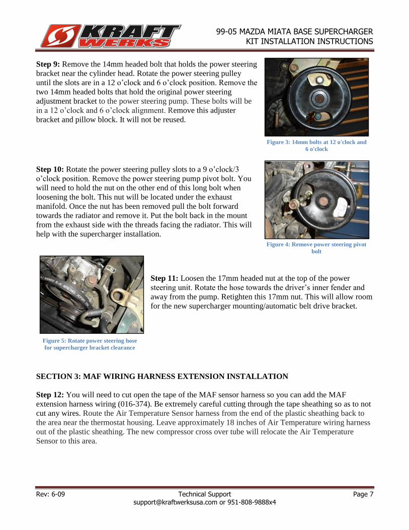
Step 9: Remove the 14mm headed bolt that holds the power steering
bracket near the cylinder head. Rotate the power steering pulley
until the slots are in a 12 o’clock and 6 o’clock position. Remove the
two 14mm headed bolts that hold the original power steering
adjustment bracket to the power steering pump. These bolts will be
in a 12 o’clock and 6 o’clock alignment. Remove this adjuster
bracket and pillow block. It will not be reused.
Step 10: Rotate the power steering pulley slots to a 9 o’clock/3
o’clock position. Remove the power steering pump pivot bolt. You
will need to hold the nut on the other end of this long bolt when
loosening the bolt. This nut will be located under the exhaust
manifold. Once the nut has been removed pull the bolt forward
towards the radiator and remove it. Put the bolt back in the mount
from the exhaust side with the threads facing the radiator. This will
help with the supercharger installation.
Step 11: Loosen the 17mm headed nut at the top of the power
steering unit. Rotate the hose towards the driver’s inner fender and
away from the pump. Retighten this 17mm nut. This will allow room
for the new supercharger mounting/automatic belt drive bracket.
SECTION 3: MAF WIRING HARNESS EXTENSION INSTALLATION
Step 12: You will need to cut open the tape of the MAF sensor harness so you can add the MAF
extension harness wiring (016-374). Be extremely careful cutting through the tape sheathing so as to not
cut any wires. Route the Air Temperature Sensor harness from the end of the plastic sheathing back to
the area near the thermostat housing. Leave approximately 18 inches of Air Temperature wiring harness
out of the plastic sheathing. The new compressor cross over tube will relocate the Air Temperature
Sensor to this area.
Figure 3: 14mm bolts at 12 o'clock and
6 o'clock
Figure 4: Remove power steering pivot
bolt
Figure 5: Rotate power steering hose
for supercharger bracket clearance
Rev: 6-09 Technical Support Page 8 [email protected] or 951-808-9888x4
99-05 MAZDA MIATA BASE SUPERCHARGER KIT INSTALLATION INSTRUCTIONS
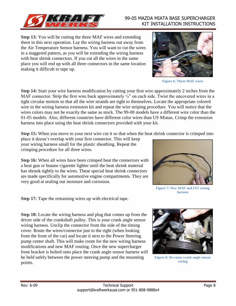
Step 13: You will be cutting the three MAF wires and extending
them in this next operation. Lay the wiring harness out away from
the Air Temperature Sensor harness. You will want to cut the wires
in a staggered pattern, as you will be extending the wiring harness
with heat shrink connectors. If you cut all the wires in the same
place you will end up with all three connectors in the same location
making it difficult to tape up.
Step 14: Start your wire harness modification by cutting your first wire approximately 2 inches from the
MAF connector. Strip the first wire back approximately ¼” on each side. Twist the uncovered wires in a
tight circular motion so that all the wire strands are tight to themselves. Locate the appropriate colored
wire in the wiring harness extension kit and repeat the wire striping procedure. You will notice that the
wires colors may not be exactly the same as stock. The 99-00 models have a different wire color than the
01-05 models. Also, different countries have different color wires than US Miatas. Crimp the extension
harness into place using the heat shrink connectors provided with your kit.
Step 15: When you move to your next wire cut it so that when the heat shrink connector is crimped into
place it doesn’t overlap with your first connector. This will keep
your wiring harness small for the plastic sheathing. Repeat the
crimping procedure for all three wires.
Step 16: When all wires have been crimped heat the connectors with
a heat gun or butane cigarette lighter until the heat shrink material
has shrunk tightly to the wires. These special heat shrink connectors
are made specifically for automotive engine compartments. They are
very good at sealing out moisture and corrosion.
Step 17: Tape the remaining wires up with electrical tape.
Step 18: Locate the wiring harness and plug that comes up from the
driver side of the crankshaft pulley. This is your crank angle sensor
wiring harness. Unclip the connector from the side of the timing
cover. Route the wires/connector just to the right (when looking
from the front of the car) and locate it next to the Power Steering
pump center shaft. This will make room for the new wiring harness
modifications and new MAF routing. Once the new supercharger
front bracket is bolted onto place the crank angle sensor harness will
be held safely between the power steering pump and the mounting
points.
Figure 6: Three MAF wires
Figure 7: New MAF and IAT wiring
harness
Figure 8: Re-route crank angle sensor
wiring

Rev: 6-09 Technical Support Page 9 [email protected] or 951-808-9888x4
99-05 MAZDA MIATA BASE SUPERCHARGER KIT INSTALLATION INSTRUCTIONS
Step 19: Remove the lower wiring harness retaining clip from the
driver side wiring harness retention bracket located on the driver
side of the timing belt cover. You will be bolting an oval wiring
harness clamp to this bracket in the next operation. This harness will
be routed just above its original location and held in place with the
aforementioned clamp.
Step 20: Install the new oval wiring harness retention clamp (016-
393) around the MAF and Air Temperature Sensor wiring harnesses
near the timing cover wiring harness bracket bolted to the timing
cover. The Air Temperature Sensor harness should be routed towards
the passenger fender while the MAF harness should be routed behind
the Power Steering pump. Install the 6x1.0x12mm flange bolt (016-
238) and flanged lock nut (016-355) through the bracket and the
retention clamp and tighten so that the wiring harness is held tightly
to the timing cover. This will keep the wiring harness safe when the
new automatic belt tensioner pulley moves through its travel. The
stock bracket can get bent too far out during timing belt installations
or even during this installation. If you find the tensioner pulley touches the oval wiring harness retaining
bracket you will need to tap the bracket back against the timing cover using a hammer and a long rod or
socket extension. Gently tap the oval clamp back against the timing cover until the wiring harness and
clamp clear the tensioner pulley. Plug the crank angle sensor connectors back together and double check
all connectors before moving to the supercharger bracket installation.
SECTION 4: ROTREX SUPERCHARGER INSTALLATION
Step 21: Remove the engine lift bracket from the driver side of the
cylinder head near the timing cover. You will not be reusing the bolt
or the bracket on a permanent basis, but you will be using the bolt
for temporary fit up during the supercharger bracket installation.
Mount the belt drive support bracket (016-165) to this threaded hole
on the driver side of the cylinder head using the 10x1.25x50mm
flange bolt (016-023) supplied with your kit. Snug this bolt up at this
time but do not tighten completely.
Figure 11: Supercharger support
bracket
Figure 9: Remove the lower wiring
harness bracket
Figure 10: Oval retention clamp

Rev: 6-09 Technical Support Page 10 [email protected] or 951-808-9888x4
99-05 MAZDA MIATA BASE SUPERCHARGER KIT INSTALLATION INSTRUCTIONS
Step 22: With the power steering pulley holes back in the 12
o’clock/6 o’clock position, install the new power steering spacer
bracket (016-138) on the power steering pump using the lower bolt
only at this point. Snug the bolt up but do not tighten completely at
this time. The upper bolt is shared by the new supercharger
mounting bracket (016-177).
Step 23: Lower the new supercharger mounting bracket into the area where the original belt adjuster
was located. Route the MAF sensor wiring harness between the mounting bracket and the timing cover.
Route it back towards the exhaust temporarily. Be sure that no wires are pinched between the mounting
bracket and the engine. With the power steering pulley still in the 12 o’clock/6 o’clock position reinstall
the upper power steering support bracket bolt through the supercharger mounting bracket, through the
power steering spacer bracket and into the power steering pump.
Step 24: Rotate the power steering pulley to the 9 o’clock/3 o’clock position. Reinstall the original
power steering pump mounting nut at this 9 o’clock position. Install the special 8x1.25x25mm flange
bolt (Bolt head cut short) through the belt tensioner mounting
bracket and into the engine block. This modified flange bolt allows
the automatic tensioner pulley to move through its travel without
being interfered with by a normal 14mm headed bolt.
Step 25: Using the original engine lift bolt, temporarily install this
bolt through the supercharger bracket and into belt drive support
bracket (016-165) Torque all supercharger mounting brackets and
lower power steering bolts/nut to 20 ft-lbs at this time. Once all bolts
and nuts are torqued you can remove the original engine lift
mounting bolt. The automatic belt adjuster will be mounted in this
location.
Step 26: Install the “T” nut (016-135), and 10x1.5x60mm stud (016-137) into the slot, and from behind,
the supercharger bracket. Install the new idler pulley (016-002) with one of the stepped spacers (016-
003) onto the “T” nut/stud. The small step should be against the bearing’s inner race. Install another
stepped spacer on the outside of the idler and secure with a 10x1.5mm flange nut (016-388). Thread the
6x1.0x70mm adjuster bolt (016-068) and 6x1.0 nut into the side of the supercharger mounting/belt
tensioner bracket loosely at this time. You will be using this 6mm bolt as an adjuster later during the
final belt tensioning sequence.
Step 27: Thread a 10x1.25x75mm flange bolt (016-006) through the automatic tensioner (016-130),
through the supercharger mounting bracket and into the supercharger support bracket bolted to the
cylinder head. Rotate the tensioner until the alignment post on the back of the tensioner aligns with the
notch cut into the top of the supercharger mounting/belt tensioner bracket. Torque this bolt to 20 ft-lbs.
Figure 12: Power steering spacer
bracket
Figure 13: Supercharger bracket
mounted

Rev: 6-09 Technical Support Page 11 [email protected] or 951-808-9888x4
99-05 MAZDA MIATA BASE SUPERCHARGER KIT INSTALLATION INSTRUCTIONS
Step 28: Bolt the banjo bolts (016-339) and banjo hose fittings (016-334) to the Rotrex supercharger.
Put one copper washer (016-338) on each side of the banjo bolt so that the banjo fitting has a “crush”
washer to seal it at the supercharger. These banjo fittings will need to be adjusted for the hose entrance
and exit directions later in the instructions.
Step 29: Install the Rotrex supercharger through the supercharger mounting bracket with the two oil
fittings facing up. Torque the 6mm allen head bolts to only 6.6 ft-lbs torque. These small bolts do not
require large amounts of torque. We recommend a small amount of Loctite on the threads before
installation.
SECTION 5: ROTREX OIL COOLER INSTALLATION
In this next section, you will be removing the plastic clips and plastic threaded fasteners that hold the
front bumper and inner liners in place. These clips and fasteners become brittle with age. Be prepared to
replace these clips if your car is over 5 years old. If they won’t unthread, you may have to use bumper
clip tool to remove them from the underside.
Step 30: Remove the four bolts from the area near
the hood latch that holds the upper part of the front
bumper in place.
Figure 14: Your Supercharger Assembly (Supercharger pulley installed later)
Figure 15: Four bumper bolts

Rev: 6-09 Technical Support Page 12 [email protected] or 951-808-9888x4
99-05 MAZDA MIATA BASE SUPERCHARGER KIT INSTALLATION INSTRUCTIONS
Step 31: From under the car remove the hardware the holds the
inner fender liners to the front bumper/under trays. Unplug the front
side marker lights and fog lamps (if applicable). Remove the
mounting hardware from behind the license plate. Remove the
mounting hardware from the very ends of the bumper where they
meet the fender opening. Pull out from the corners and this will
“pop” the plastic retainers from the bumper ends. Remove the front
bumper assembly.
Step 32: Remove the five bolts
that hold the center air flow cowl to the under tray and chassis.
Remove the two plastic retainer screws where the cowl meets the
front bumper mount and remove the cowl. This will give you access
to the air conditioning condenser.
Step 33: Mount the Rotrex oil cooler to the front of the air
conditioning condenser using the mounting kit provided. Install the
oil cooler in the lower half of the radiator/air conditioning area so
that the oil cooler gets direct air flow. The oil cooler will mount to
the top and bottom of the air conditioning condenser flanges (folded aluminum lip). Slide two billet
slotted clamps (016-384) across the top of the air conditioning condenser from the passenger side
towards the middle while pulling down gently on the A/C condenser to get the slotted brackets onto the
condenser. These brackets have a flat machined surface facing the front of the car.
Step 34: Install the two bottom oil cooler billet mounts over the folded edge of the air conditioning
condenser.
Step 35: With the billet mounts in place, it is time to install the
vertical oil cooler struts/cooler. Bolt the oil cooler (016-161) to the
vertical struts (016-385) using the 6x1.0x10mm flange bolts (016-
051) and 6x1.0 flange nuts (016-059) provided. Bolt the cooler so
that the fittings face away from the slots in the vertical strut.
Step 36: Bolt the oil cooler struts to the four billet mounts using the
6x1.0x35mm flange bolts (016-060) and (4) 3/8” aluminum spacers
(016-382) with the spacers between the vertical strut and the billet
aluminum A/C condenser mounts. The slots on the struts should be
at the bottom and the oil cooler fittings should be facing the hood latch. Torque all bolts to 7 ft-lbs. We
recommend using Loctite thread locking adhesive to all bolts.
Locate the Rotrex oil reservoir sub assembly. This assembly consists of: (2) wrap around Rotrex
reservoir mounts (016-335), (2) 6x1.0x14mm allen bolts (016-337), (2) 6x1.0 nyloc nuts (016-199), (1)
6x1.0x60mm flange bolt (016-218), (1) 1.5” spacer (016-383), (1) 6x1.0 flange nyloc nut, (1) top billet
mounting bracket (016-380), (1) 8 x 1.25 x 20mm flange bolt (016-026), (1) 8 x 1.25 flange nut (016-
022), and (1) 8mm flat washer (016-301). You will be mounting the reservoir mounting bracket to an
Figure 16: Loosen bumper
Figure 17: Plastic retainers in cowl
Figure 18: Oil Cooler Assembly

Rev: 6-09 Technical Support Page 13 [email protected] or 951-808-9888x4
99-05 MAZDA MIATA BASE SUPERCHARGER KIT INSTALLATION INSTRUCTIONS
existing hole behind the passenger head lamp with the 8mm flat washer between the billet mounting
bracket and the radiator support.
Step 37: Install the clamps around the Rotrex oil reservoir using the allen bolts and nyloc nuts to hold
the clamps tight. The top clamp should be approximately ½ inch from the top of the reservoir with the
90° tab facing down. Install the 6x1.0x60mm flange bolt through the 6mm hole in the billet mounting
bracket and through the top Rotrex reservoir mount. Install the 1.5” spacer between the top Rotrex
clamp and the bottom Rotrex clamp. Finish the subassembly by installing and tightening the 6x1.0
flange nyloc nut on the bottom of the lower Rotrex clamp. Rotate the Rotrex reservoir so that the banjo
fitting hole of the reservoir is opposite the mounting tab of the clamp. This operation is done so that you
get acquainted with the reservoir mounting. The final mounting will not be finished until all Rotrex oil
lines are routed.
Step 38: Bolt the banjo bolts (016-339) and banjo hose fittings (016-334) to the oil reservoir (016-326).
Put one copper washer (016-338) on each side of the banjo bolt so that the banjo fitting has a “crush”
washer to seal it at the reservoir. These banjo fittings will need to be adjusted for the hose entrance and
exit directions before you finish. When mounted correctly the banjo fittings will both face back towards
the firewall.
You will find the supplied oil lines may be longer than required for you vehicle. We have made them
longer than needed to account for any modifications or other accessories you may have on your vehicle.
If the hose is longer than required simply cut the excess hose until you have a quality fit and your install
is aesthetically pleasing.
Step 39: Connect a 45” oil line (016-398) from the Rotrex “OUT”
fitting (closest to the engine) and route it towards the driver’s fender
and the top shock mount. Thread it between the driver’s headlight
and the vertical air deflector/relay mount. There is a small opening
between the radiator and the radiator support. Route this hose
between the radiator and the radiator support and connect it to the oil
cooler using the spring clamps (016-214) provided. Locate one of
the four pieces of ½”x 2” hose (016-403) that has been cut
lengthwise. Slide one piece over the Rotrex oil hose where it passes
through the radiator area to protect the Rotrex hose. Repeat this
procedure for each hose as it passes through the radiator area.
Step 40: Connect another 32” hose (016-395) from the remaining oil cooler fitting and route it between
the radiator and the radiator support on the passenger side of the car similar to the way you did the
driver’s side. This hose will connect to the top of the Rotrex oil reservoir after we mount the reservoir.
Be sure to route all oil hoses away from any sharp objects or belts so that the hose does not get damaged.
Secure using the spring clamps (016-214) provided.
Step 41: Clamp a 5/16”ID x 2.5” hose (016-396) to the lower fitting on the Rotrex oil reservoir. Install
the Rotrex oil filter (016-325) into the open end of this hose with the “flow” going away from the
Figure 19: Driver's side oil hose routing

Rev: 6-09 Technical Support Page 14 [email protected] or 951-808-9888x4
99-05 MAZDA MIATA BASE SUPERCHARGER KIT INSTALLATION INSTRUCTIONS
reservoir and clamp with the spring clamps (016-214) provided. The banjo fitting should be facing away
from the billet upper mount.
Step 42: It is time to mount the Rotrex oil reservoir. Lay the 8mm
flat washer over the hole in the radiator support as seen in the photo.
This hole is between the top radiator mount and the hood height
adjustment rubber. With the 8mm flat washer laying over the hole in
the radiator support, carefully lower the Rotrex reservoir with the
short hose and filter already attached over this washer. Install the
8x1.25x20mm flange bolt through the billet bracket, through the
washer, through the radiator support and finish by installing an
8x1.25mm flange nut on the underside of the radiator support.
Tighten to 16 ft-lbs.
Step 43: Install the large cushion clamp (016-071) and 6x1.0x16mm
flange bolt (016-054) around the Rotrex oil filter and bolt it to the
existing threaded hole in the horizontal area behind the reservoir in
the inner fender area. See the photo for location. On some models
there is an air conditioning tubing mount bolted to this threaded
hole. If so, you can use the original bolt and share the threaded hole
with the large cushion clamp and the A/C tubing mount. Tighten the
flanged bolt to 9 ft-lbs.
Step 44: Install the oil cooler “OUT” hose to the Rotrex upper reservoir “IN” banjo fitting. Secure with
spring clamps provided (016-214).
Step 45: Clamp a 5/16”ID x 89” hose (016-397) onto the
outlet of the Rotrex oil filter with the spring clamp
provided (016-214). Route it back towards the firewall
and make a nice gentle loop in it and route it back towards
the fuel line area. Loop it up and forward so that it passes
through the radiator support where the oil cooler hose was
routed to the top of the Rotrex reservoir banjo fitting.
Route it across the underside of the radiator support.
Secure it with (2) #10 cushion clamps (016-063) to the
underside of the radiator support using (2) 6x1.0x16mm
flange bolts (016-054) and 6x1.0 flange nuts (016-059) as
seen in the photo. Route this secured hose through the
opening in the radiator support the oil cooler hose passed
through on the driver’s side. Route this hose next to your Rotrex “OUT” hose and connect it to the “IN”
fitting of the Rotrex. Secure with the spring clamps provided (016-214).
Figure 20: Rotrex reservoir mounting
Figure 21: Rotrex oil filter mounting
Figure 22: Loop in 89" oil hose

Rev: 6-09 Technical Support Page 15 [email protected] or 951-808-9888x4
99-05 MAZDA MIATA BASE SUPERCHARGER KIT INSTALLATION INSTRUCTIONS
Step 46: Rotate the banjo fittings, if needed, so that all oil hoses have a smooth radius to enter and exit
the reservoir and the Rotrex supercharger. Recheck the banjo fittings so that you are sure they are tight
and that they are pointed in the correct direction. You may have to remove the reservoir from the
radiator support a couple times until you get the angle you require.
IT IS VERY IMPORTANT THAT YOU INSTALL THESE ROTREX OIL RESERVOIR OIL LINES
TO THE PROPER FITTINGS ON THE ROTREX OIL RESERVOIR. THE OIL LINE “FROM” THE
OIL COOLER CONNECTS TO THE “TOP” OF THE ROTREX OIL RESERVOIR. THE BOTTOM
FITTING OF THE ROTREX RESERVOIR CONNECTS TO THE OIL FILTER, AND THE OIL
FILTER LINE GOES TO THE “OIL IN” BANJO FITTING ON THE ROTREX SUPERCHARGER.
FAILURE TO CONNECT THESE HOSES CORRECTLY WILL CAUSE THE ROTREX
SUPERCHARGER TO FAIL.
Figure 23: Radiator support oil hose routing and
mounting from the underside Figure 24: Rotrex oil hose mounting bolts from top
Figure 25: Rotrex Oil Circuit

Rev: 6-09 Technical Support Page 16 [email protected] or 951-808-9888x4
99-05 MAZDA MIATA BASE SUPERCHARGER KIT INSTALLATION INSTRUCTIONS
Step 47: Once you have all the hoses routed correctly and banjo fittings rotated correctly, tighten all
clamps, brackets, and fittings. Fill the reservoir at this time but do not try to start the engine. Instructions
for starting a Rotrex for the first time are outlined later in the instructions.
SECTION 6: PULLEY AND BELT INSTALLATION
Step 48: Install the new supercharger pulley (016-133) onto the Rotrex supercharger using the six
M6x1.0x12mm allen bolts (016-331) provided in the Pulley & Belt Kit (006-022). Use a small amount
of Loctite on each bolt and torque evenly to 7 ft-lbs.
Step 49: Install the serpentine drive belt (016-160) from the crankshaft pulley to the air conditioning
compressor pulley. From the a/c pulley go straight up and over the power steering pulley from the 3
o’clock position towards the 12 o’clock position. With the static belt adjuster’s 2” idler pulley in its
loosest setting, continue with the belt over the 2” idler pulley and around the supercharger pulley. From
the supercharger pulley the belt will go under the automatic belt adjuster and back to the crankshaft
pulley. You will need to use a 3/8” ratchet to put tension on the automatic belt adjuster so that the belt
can be routed under the automatic belt tensioner pulley and down to the crankshaft. The first installation
of the belt will be tight. You may have to turn the crankshaft with a 21mm wrench/socket while working
the belt onto the crankshaft the first time. The belt will stretch during initial break in and warm up
period, and will need to be readjusted after about 10 minutes of use. Once the initial static adjustment
has been made, the automatic tensioner will keep the belt properly adjusted.
Step 50: You will need to pre-set the belt tension using the static belt adjuster so that the automatic belt
tensioner system can do its job. While holding the automatic belt tensioner in an open position, tighten
the 6x1.0x70mm adjuster bolt on the side of the supercharger mounting bracket near the power steering
pulley. Continue this adjustment until there is at least a ½” gap between the power steering pulley and
the bottom of the serpentine belt when viewing the power steering pulley at approximately the 10
Figure 26: Belt Routing (No A/C shown)

Rev: 6-09 Technical Support Page 17 [email protected] or 951-808-9888x4
99-05 MAZDA MIATA BASE SUPERCHARGER KIT INSTALLATION INSTRUCTIONS
o’clock position. Tighten the 2” static idler pulley 14mm nut at this time. Tighten the 10mm headed nut
that holds the static adjuster bolt in place. Your belt will now be adjusted automatically for stretch
during acceleration and deceleration. This will also improve fuel economy and increase belt and pulley
life.
**Special Note**
The KraftWerks Gates Racing serpentine belt provided with your supercharger system is constructed of
extremely high quality Kevlar and EPDM materials that give it double the life of traditional serpentine
belts. These materials also cause the belt to produce a squeaking noise when first started. This is normal
and will disappear within 10 minutes of running.
SECTION 7: MAF SENSOR INSTALLATION
Step 51: Install the molded supercharger inlet hose (016-142) onto
the center of the supercharger inlet with the supercharger insert
(016-390) in place. The 3/8” fitting will be facing up and the 1”
fitting will be facing down. Gently tighten a #36 hose clamp (016-
329) around the hose to secure it. Some models have the windshield
washer bottle located in the area where the molded hose needs to be.
Unbolt the washer reservoir from the lower frame rail and the upper
support. Move the bottle back 1.625” to the back 8x1.25 hole in the
bracket. Install the washer bottle support bracket (016-441) using the
original 8mm flange bolt and the new 8x1.25x20mm flange bolt
(016-026) and 8x1.25mm flange nut (016-022) provided.
Step 52: Locate the 3/8”OD valve cover vent restrictor (016-434) supplied with your kit and install it
into the 3/8”ID x 6” hose (016-147). Install the 3/8” x 90° vent fitting (016-157) into the top of the
silicone supercharger inlet hose and connect the 3/8” x 6” valve cover vent hose between this fitting and
the valve cover.
Step 53: Install the bypass valve (016-108) into the 1” hose on the
bottom of the molded inlet hose. Mount it so that the small vacuum
fitting faces down. Tighten a #16 hose clamp (016-112) around this
bypass valve. Leave the hose clamp loose at this time as you will be
aligning the bypass valve with the hose spigot coming from the
supercharger outlet tube later in the installation.
Step 54: Install the 1”x 90° molded hose (016-402) to the bypass
valve with the 90° end facing the front of the car. Tighten with the
#16 hose clamp (016-112) supplied for future connection to the supercharger outlet tubing.
Step 55: Install the 2.75”ID x 6” MAF connector tube into the open end of the molded inlet hose and
secure with a #44 hose clamp (016-222).
Figure 28: Bypass Valve Routing
Figure 27: Windshield washer reservoir
bracket (ABS Only)
Rev: 6-09 Technical Support Page 18 [email protected] or 951-808-9888x4
99-05 MAZDA MIATA BASE SUPERCHARGER KIT INSTALLATION INSTRUCTIONS
Step 56: Install a 2.75”ID x 90° silicone hose (016-302) onto the open end of the MAF connector tube.
Install the longer end of the silicone hose onto the MAF connector tube. Rotate the hose so that it faces
forward towards the driver’s headlight. Finish by installing (2) #44 hose clamps (016-222) onto this
hose.
Step 57: Insert the MAF sensor into the short “leg” of the silicone hose with the connector plug for the
MAF sensor facing the engine. Clamp with the #44 hose clamps provided.
Step 58: Install the KraftWerks air filter (016-181) to the end of the MAF sensor. Tighten with the hose
clamp provided.
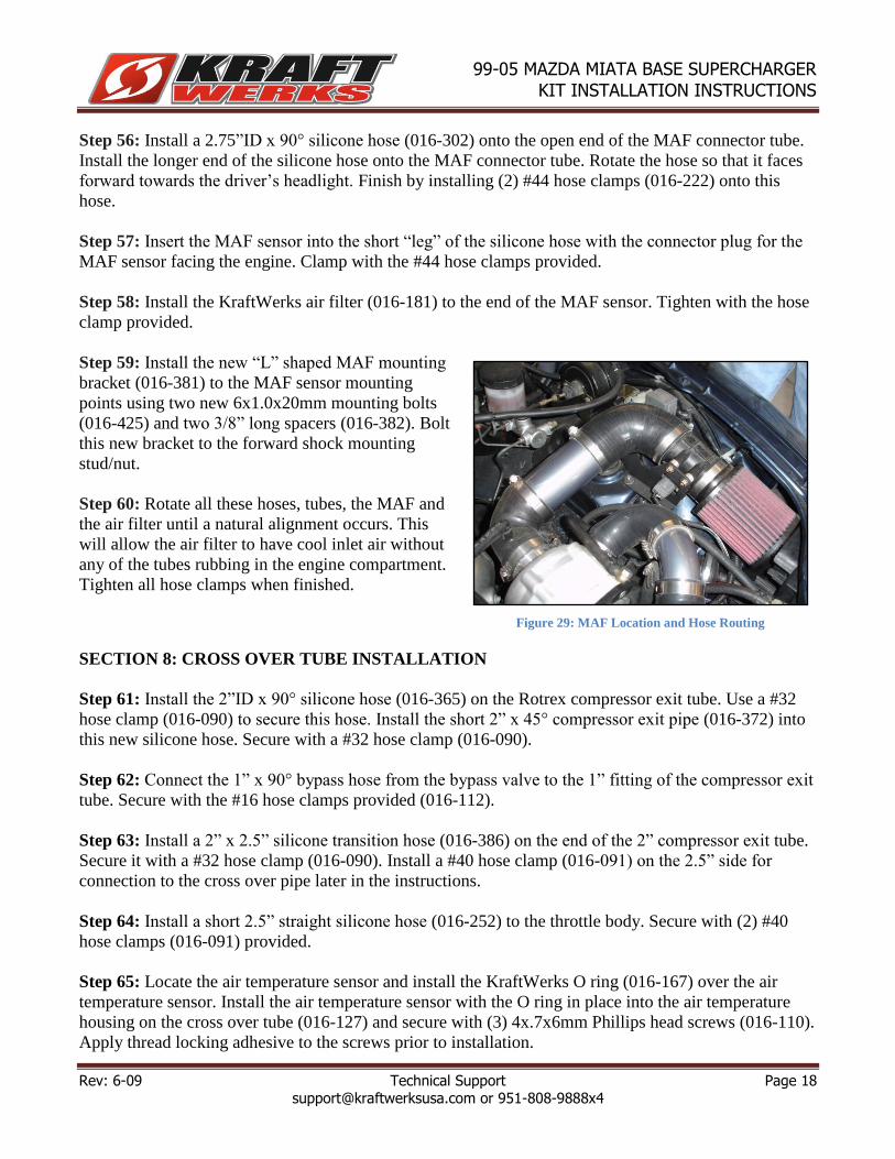
Step 59: Install the new “L” shaped MAF mounting
bracket (016-381) to the MAF sensor mounting
points using two new 6x1.0x20mm mounting bolts
(016-425) and two 3/8” long spacers (016-382). Bolt
this new bracket to the forward shock mounting
stud/nut.
Step 60: Rotate all these hoses, tubes, the MAF and
the air filter until a natural alignment occurs. This
will allow the air filter to have cool inlet air without
any of the tubes rubbing in the engine compartment.
Tighten all hose clamps when finished.
SECTION 8: CROSS OVER TUBE INSTALLATION
Step 61: Install the 2”ID x 90° silicone hose (016-365) on the Rotrex compressor exit tube. Use a #32
hose clamp (016-090) to secure this hose. Install the short 2” x 45° compressor exit pipe (016-372) into
this new silicone hose. Secure with a #32 hose clamp (016-090).
Step 62: Connect the 1” x 90° bypass hose from the bypass valve to the 1” fitting of the compressor exit
tube. Secure with the #16 hose clamps provided (016-112).
Step 63: Install a 2” x 2.5” silicone transition hose (016-386) on the end of the 2” compressor exit tube.
Secure it with a #32 hose clamp (016-090). Install a #40 hose clamp (016-091) on the 2.5” side for
connection to the cross over pipe later in the instructions.
Step 64: Install a short 2.5” straight silicone hose (016-252) to the throttle body. Secure with (2) #40
hose clamps (016-091) provided.
Step 65: Locate the air temperature sensor and install the KraftWerks O ring (016-167) over the air
temperature sensor. Install the air temperature sensor with the O ring in place into the air temperature
housing on the cross over tube (016-127) and secure with (3) 4x.7x6mm Phillips head screws (016-110).
Apply thread locking adhesive to the screws prior to installation.
Figure 29: MAF Location and Hose Routing

Rev: 6-09 Technical Support Page 19 [email protected] or 951-808-9888x4
99-05 MAZDA MIATA BASE SUPERCHARGER KIT INSTALLATION INSTRUCTIONS
Step 66: Install the cross over tube from the throttle body hose to the compressor outlet pipe/transition
hose. Secure with hose clamps provided. Finish this installation by rotating all hoses and tubes until a
natural alignment is found and no pipes or tubes rub against anything. Tighten all hose clamps at this
time. Plug the air temperature sensor plug onto the air temperature sensor in the cross over tube.
SECTION 9: SUPERCARD FUEL MANAGEMENT INSTALLATION
Step 67: You will be removing the top of the intake manifold so that you can connect the SuperCard
wiring to the fuel injectors. You do not have to remove the throttle body or any of the coolant hoses
from the car. But you will be removing the throttle body temporarily so that the intake manifold can be
taken apart. Remove the bracket that holds the ground wires near the top of the throttle body. Unplug the
cam angle sensor from the valve cover. Unplug the throttle position sensor and the fast idle sensor plug
from the throttle body. From the rear of the intake manifold unplug the EGR (Exhaust Gas
Recirculation) sensor and the variable intake manifold sensor mounted directly behind the EGR sensor.
Follow the wiring harness forward and unplug the two main wiring plugs just below the throttle body.
This will allow you to move the wiring harness to gain access to the fuel injectors.
Step 68: Remove the PCV hose from the valve cover and the intake manifold.
Step 69: Remove the Power Brake hose from the intake manifold and the hard metal line that the Power
Brake hose connects to and remove the hose from the car.
Step 70: Remove the cruise control hose from the back of the intake manifold if applicable.
Step 71: Remove the throttle cable from the throttle cable bracket.
Remove the two bolts and two nuts that hold the throttle body to the
intake manifold and remove the throttle body from the intake
manifold. Let it lay in the engine compartment with the coolant
hoses still attached. Remove the 12mm headed bolts that hold the
top of the intake manifold to the bottom. Remove two 12mm headed
bolts from the bracket just below the throttle body that is used as a
support for the intake manifold. On some models there is a ground
wire attached to one of the lower support bolts. Don’t forget to
Figure 30: Crossover Tube Installed
Figure 31: Remove intake manifold
bolts

Rev: 6-09 Technical Support Page 20 [email protected] or 951-808-9888x4
99-05 MAZDA MIATA BASE SUPERCHARGER KIT INSTALLATION INSTRUCTIONS
reinstall that ground wire or your car will run poorly when you are finished.
Step 72: At this point you just need to lift up on the intake manifold
and set it off to one side so that you can work near the injectors.
Cover the open intake manifold so that you don’t drop any debris or
tools down into the engine.
Step 73: Remove the two 12mm headed bolts that hold the EGR
valve onto the intake manifold. Do not lose the metal EGR gasket. It
is reusable. Removing the EGR valve helps with fuel injector
removal and installation.
Step 74: It is possible to install
the SuperCard wiring without
removing the fuel injectors but
most Miatas we’ve worked on
have the injector clips stuck to the
injectors and are very difficult to
get off the injectors without
removing the fuel rail/injector
assembly from the intake
manifold. Once you’ve found the
fuel injectors and their harness
unplug the injector clips from the injectors. These can be difficult if the clips are old and heat weathered
so be gentle and use penetrating spray to loosen them up. We recommend removing the three 12mm
headed bolts that hold the fuel rail to the cylinder head. Be careful not to lose the three plastic insulating
rings that ride between the cylinder head and the fuel rail when the fuel rail is unbolted from the engine.
This is also a good time to remove your fuel injectors and have them cleaned and flow-tested by RC
Engineering.
Step 75: Route the injector
harness from the Miata SuperCard
around the back of the engine and
clip all of the female injector clips
onto each injector. Then plug the
male injector clips from the
SuperCard into the stock injector
clips. Check the male pins of the
SuperCard prior to plugging them
into the stock injector clips. These
male pins are unsupported until plugged into the stock pins. If the
male pins aren’t completely straight when plugging into the stock
injector clips the male pins could get bent over and not make a
complete connection. Once you are confident of the injector leads
Figure 32: EGR
Figure 33: Fuel Rail Bolts Figure 34: Insulating rings between fuel
rail and cylinder head
Figure 35: SuperCard harness properly
plugged in
Figure 36: Fuel injection system
assembled

Rev: 6-09 Technical Support Page 21 [email protected] or 951-808-9888x4
99-05 MAZDA MIATA BASE SUPERCHARGER KIT INSTALLATION INSTRUCTIONS
and their connection reinstall the top of the intake manifold in reverse order of disassembly.
Step 76: Clean the firewall in the area near the windshield wiper motor with alcohol or similar non-oil
cleaner. Attach the SuperCard to this clean area using the Dual Lock Velcro (016-286) supplied with
your kit. Attach the ground wire for the SuperCard to the bolt that the wiper motor ground wire is
attached to.
Step 77: On the top of the intake manifold there is a vacuum fitting for the cruise control. If you do not
have cruise control there will be a cap on the vacuum fitting. You will be using that fitting for a vacuum
source for the bypass valve and the SuperCard. If you have cruise control, you will need two vacuum Ts
(016-260) with 2.5” vacuum hoses connected to them to make the cruise control, the SuperCard, and the
Bypass valve work. If you don’t have cruise control, you will only need one vacuum “T” and a 2.5”
vacuum hose. We supply a long piece of vacuum hose so that you can cut it to length for your model and
country. A small vacuum hose restrictor (016-435) needs to be installed between the intake manifold
vacuum fitting and the bypass valve/SuperCard. The best place is between the intake manifold fitting
and the first vacuum "T". Install the T/vacuum hose so that one leg of the T faces back towards the
firewall directly above the main wire harness. The other leg of the T should face the driver’s fender.
Connect the 5/32” vacuum tubing to each leg of the “T”. One piece (approx. 14” long) should travel
back to the SuperCard fuel box. Another piece of vacuum hose (approx. 50” long) should be routed
across the back of the firewall where the power brake metal piping transmits the vacuum signal to the
power brake booster. Secure the vacuum hose to the metal piping with plastic ties. Connect the long
vacuum hose routed across the firewall to the bypass valve. Connect SuperCard vacuum hose to the
SuperCard by using the small hose reducer (016-257) supplied.
Step 78: Plug the MAF in at this time.
SECTION 10: PRIMING THE ROTREX SUPERCHARGER SYSTEM
Step 79: It is time to prime the Rotrex supercharger. There are two methods to priming the Rotrex oil
system:
If you have compressed air, loosen the “IN” fitting on the Rotrex compressor (furthest from the engine)
and gently blow air into the full Rotrex oil reservoir while covering the top of the reservoir with a shop
towel. Always wear eye protection when using compressed air. Continue blowing into the reservoir until
oil leaks from the “IN” fitting of the Rotrex compressor. Tighten the fitting once you see oil flowing
through the system. Watch the Rotrex reservoir carefully during this initial start up as it will be filling
the oil cooler and lines during this initial start up. Make sure the reservoir does not run dry.
If you don’t have compressed air, unplug all the spark plugs leads from the spark plug coils. Loosen the
Rotrex “OUT” oil fitting on the supercharger. It will be the fitting closest to the engine block. Have a
helper watch the “OUT” fitting to verify when oil starts leaking from this fitting. Crank the engine for
10 seconds. If you do not see oil leak from the “OUT” fitting, continue this 10-second procedure 5 more
times letting the starter cool between intervals. If you still haven’t seen oil come from the “OUT” fitting,
plug the spark plugs leads back in and start the car; let it run for 3 seconds. Repeat this procedure until

Rev: 6-09 Technical Support Page 22 [email protected] or 951-808-9888x4
99-05 MAZDA MIATA BASE SUPERCHARGER KIT INSTALLATION INSTRUCTIONS
you see oil leak from the “OUT” fitting. Once oil leaks from the “OUT” banjo fitting, tighten the “OUT”
banjo fitting and start the car. Watch the Rotrex reservoir carefully during this initial start-up, as it will
be filling the oil cooler and lines. Make sure the Rotrex oil reservoir does not run dry in the initial start-
up.
Step 80: Check the Rotrex oil level once the engine has warmed up completely. ALWAYS CHECK
THE ROTREX OIL LEVEL WHEN THE ENGINE IS COMPLETELY WARMED UP. RAISE THE
RPM TO 2000 RPM AND HOLD IT THERE FOR 15 SECONDS. ALLOW THE CAR TO COME TO
AN IDLE AND CHECK THE ROTREX OIL LEVEL AFTER THE CAR HAS COME BACK TO AN
IDLE.
THE ROTREX OIL LEVEL SHOULD BE ABOUT HALFWAY BETWEEN THE MIN AND
MAX ON THE ROTREX DIP STICK ONCE THE OIL SYSTEM IS LEVEL.*
*Do not overfill the Rotrex oil reservoir. If you overfill the Rotrex oil reservoir, it will leak from the
vented cap when you are in the upper RPM ranges. The Rotrex system draws oil through the
supercharger and sends it, at low pressure and volume, to the oil cooler. It takes some time for the
system to find its “normal” operating level. Follow the instructions for bringing the engine to 2000RPM
and then check the oil immediately after bringing it to an idle with the engine completely warmed up.
Step 81: Double-check all the connections and vacuum hoses. Check your engine oil level and fill if
necessary.
Enjoy your KraftWerks Supercharger System!
Figure 37: Proper Rotrex Oil Level


