9.8 Valve Pin Height Adjustment PNC4508B / PNC6018B Series
4
EN C P T A Master Language is English Hot Runner System Instruction Manual SVC-17-0001_EN-Rev03 RESTRICTED: Property of Synventive. - 313 - All rights reserved. Errors and omissions excepted For limited third party distribution based on need and intended use. © 2015 Synventive Molding Solutions Service and Maintenance / Valve Pin Height Adjustment PNC4508B / PNC6018B Series 9.9 Valve Pin Height Adjustment PNC4508B / PNC6018B Series Precondition for the following steps are to be performed with the Hot Runner installed in the mold, and the system at operating temperature. Hot Surfaces Hazard Contact between the skin and hot surfaces could result in burns. Use personal protective equipment, such as gloves, apron, sleeves and face protection, to guard against burns. When servicing or handling the hot runner system outside the manifold plates or the injection molding machine, care must be taken to heed the hot surface exposure warnings. 9.9.1 Valve Pin Adjustment Tool Kit Doc003767.png Tool Kit for PNC4508B ATCYL21 No. Description Item (T5.1) Adjustment Tool Typ01 ATCYL2101 (T5.2) Adjustment Tool Typ02 ATCYL2102 (T5.3) Adjustment Tool Typ03 ATCYL2103 (T5.4) Retaining ring DIN471-16x1 (T5.5) Socket head cap screws DIN912-M4x20-12.9 Tool Kit for PNC6018B ATCYL22 No. Description Item (T5.1) Adjustment Tool Typ01 ATCYL2201 (T5.2) Adjustment Tool Typ02 ATCYL2202 (T5.3) Adjustment Tool Typ03 ATCYL2203 (T5.4) Retaining ring DIN471-25x1.2 (T5.5) Socket head cap screws DIN912-M4x20-12.9
Transcript of 9.8 Valve Pin Height Adjustment PNC4508B / PNC6018B Series

EN
C P
T A
Master Language is English Hot Runner System Instruction Manual SVC-17-0001_EN-Rev03RESTRICTED: Property of Synventive. - 313 - All rights reserved. Errors and omissions exceptedFor limited third party distribution based on need and intended use. © 2015 Synventive Molding Solutions
Service and Maintenance / Valve Pin Height Adjustment PNC4508B / PNC6018B Series
9.9 Valve Pin Height Adjustment PNC4508B / PNC6018B SeriesPrecondition for the following steps are to be performed with the Hot Runner installed in the mold, and the system at operating temperature.
Hot Surfaces HazardContact between the skin and hot surfaces could result in burns.Use personal protective equipment, such as gloves, apron, sleeves and face protection, to guard against burns.When servicing or handling the hot runner system outside the manifold plates or the injection molding machine, care must be taken to heed the hot surface exposure warnings.
9.9.1 Valve Pin Adjustment Tool Kit
Doc003767.png
Tool Kit for PNC4508B ATCYL21No. Description Item
(T5.1) Adjustment Tool Typ01
ATCYL2101
(T5.2) Adjustment Tool Typ02
ATCYL2102
(T5.3) Adjustment Tool Typ03
ATCYL2103
(T5.4) Retaining ring DIN471-16x1(T5.5) Socket head
cap screwsDIN912-M4x20-12.9
Tool Kit for PNC6018B ATCYL22No. Description Item
(T5.1) Adjustment Tool Typ01
ATCYL2201
(T5.2) Adjustment Tool Typ02
ATCYL2202
(T5.3) Adjustment Tool Typ03
ATCYL2203
(T5.4) Retaining ring DIN471-25x1.2(T5.5) Socket head
cap screwsDIN912-M4x20-12.9
EN
C P
T A
Master Language is English Hot Runner System Instruction Manual SVC-17-0001_EN-Rev03RESTRICTED: Property of Synventive. - 314 - All rights reserved. Errors and omissions exceptedFor limited third party distribution based on need and intended use. © 2015 Synventive Molding Solutions
Service and Maintenance / Valve Pin Height Adjustment PNC4508B / PNC6018B Series
9.9.2 Adjustment at mounted Hot Runner System
Hot Surfaces HazardContact between the skin and hot surfaces could result in burns.
NOTICEThe actuator is covered with a plate, containing the pneu-matic access to the actuator.
1) Enable access to the actuator.
Doc003768.png
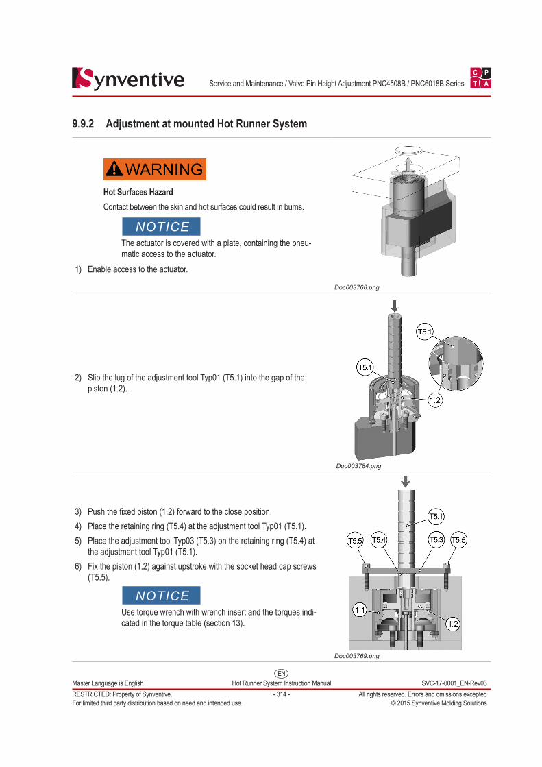
2) Slip the lug of the adjustment tool Typ01 (T5.1) into the gap of the piston (1.2).
Doc003784.png
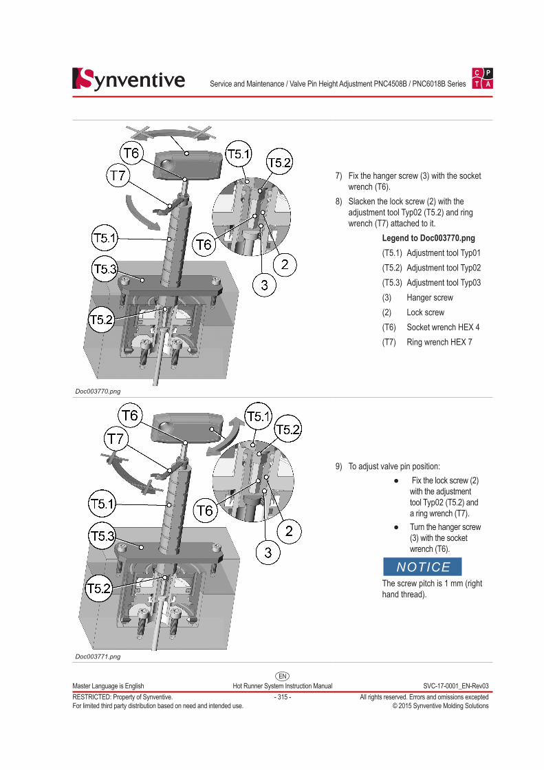
3) Push the fixed piston (1.2) forward to the close position.4) Place the retaining ring (T5.4) at the adjustment tool Typ01 (T5.1).5) Place the adjustment tool Typ03 (T5.3) on the retaining ring (T5.4) at
the adjustment tool Typ01 (T5.1).6) Fix the piston (1.2) against upstroke with the socket head cap screws
(T5.5).
NOTICEUse torque wrench with wrench insert and the torques indi-cated in the torque table (section 13).
Doc003769.png
EN
C P
T A
Master Language is English Hot Runner System Instruction Manual SVC-17-0001_EN-Rev03RESTRICTED: Property of Synventive. - 315 - All rights reserved. Errors and omissions exceptedFor limited third party distribution based on need and intended use. © 2015 Synventive Molding Solutions
Service and Maintenance / Valve Pin Height Adjustment PNC4508B / PNC6018B Series
Doc003770.png
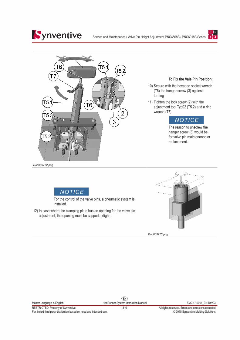
7) Fix the hanger screw (3) with the socket wrench (T6).
8) Slacken the lock screw (2) with the adjustment tool Typ02 (T5.2) and ring wrench (T7) attached to it.
Legend to Doc003770.png(T5.1) Adjustment tool Typ01(T5.2) Adjustment tool Typ02(T5.3) Adjustment tool Typ03(3) Hanger screw(2) Lock screw(T6) Socket wrench HEX 4(T7) Ring wrench HEX 7
Doc003771.png
9) To adjust valve pin position: ● Fix the lock screw (2)
with the adjustment tool Typ02 (T5.2) and a ring wrench (T7).
● Turn the hanger screw (3) with the socket wrench (T6).
NOTICEThe screw pitch is 1 mm (right hand thread).
EN
C P
T A
Master Language is English Hot Runner System Instruction Manual SVC-17-0001_EN-Rev03RESTRICTED: Property of Synventive. - 316 - All rights reserved. Errors and omissions exceptedFor limited third party distribution based on need and intended use. © 2015 Synventive Molding Solutions
Service and Maintenance / Valve Pin Height Adjustment PNC4508B / PNC6018B Series
Doc003772.png
To Fix the Vale Pin Position:10) Secure with the hexagon socket wrench
(T6) the hanger screw (3) against turning
11) Tighten the lock screw (2) with the adjustment tool Typ02 (T5.2) and a ring wrench (T7).
NOTICEThe reason to unscrew the hanger screw (3) would be for valve pin maintenance or replacement.
NOTICEFor the control of the valve pins, a pneumatic system is installed.
12) In case where the clamping plate has an opening for the valve pin adjustment, the opening must be capped airtight.
Doc003773.png