98 Expedition O/G U. - fordservicecontent.com · The Check Engine indicator light ... alarm system...
216
Before driving Introduction 2 Instrumentation 4 Controls and features 20 Seating and safety restraints 60 Starting and driving Starting 92 Driving 98 Roadside emergencies 127 Servicing Maintenance and care 150 Capacities and specifications 200 Reporting safety defects 207 Index 208 All rights reserved. Reproduction by any means, electronic or mechanical including photocopying, recording or by any information storage and retrieval system or translation in whole or part is not permitted without written authorization from Ford Motor Company. Copyright r 1997 Ford Motor Company Elemental Chlorine Free Contents 1
-
Upload
doankhuong -
Category
Documents
-
view
214 -
download
0
Transcript of 98 Expedition O/G U. - fordservicecontent.com · The Check Engine indicator light ... alarm system...

Before driving
Introduction 2
Instrumentation 4
Controls and features 20
Seating and safety restraints 60
Starting and driving
Starting 92
Driving 98
Roadside emergencies 127
Servicing
Maintenance and care 150
Capacities and specifications 200
Reporting safety defects 207
Index 208
All rights reserved. Reproduction by any means, electronic or mechanicalincluding photocopying, recording or by any information storageand retrieval system or translation in whole or part is not permitted withoutwritten authorization from Ford Motor Company.
Copyright r 1997 Ford Motor CompanyElemental Chlorine Free
Contents
1

ICONS
Indicates a warning. Read thefollowing section on Warnings fora full explanation.
Indicates vehicle informationrelated to recycling and otherenvironmental concerns will follow.
Correct vehicle usage and theauthorized disposal of wastecleaning and lubrication materialsare significant steps towardsprotecting the environment.
WARNINGSWarnings provide informationwhich may reduce the risk ofpersonal injury and preventpossible damage to others, yourvehicle and its equipment.
BREAKING-IN YOUR VEHICLEThere are no particular breaking-inrules for your vehicle. During thefirst 1 600 km (1 000 miles) ofdriving, vary speeds frequently.This is necessary to give themoving parts a chance to break in.
If possible, you should avoid fulluse of the brakes for the first1 600 km (1 000 miles).
INFORMATION ABOUT THISGUIDEThe information found in thisguide was in effect at the time ofprinting. Ford may change the
Introduction
2

contents without notice andwithout incurring obligation.
SPECIAL NOTICES
Using your vehicle as asnowplow
Do not use this vehicle forsnowplowing.
Using your vehicle as anambulance
Do not use this vehicle asan ambulance.
Your vehicle is not equipped withthe Ford Ambulance Preparationpackage.
Notice to owners of utility typevehiclesBefore you drive your vehicle,please read this Owner’s Guidecarefully. Your vehicle is not apassenger car. As with othervehicles of this type, failure tooperate this vehicle correctly mayresult in loss of control or anaccident.
Be sure to read Driving off roadin the Driving chapter as well asthe “Four Wheeling” supplementincluded with 4WD and utility typevehicles.
Introduction
3

10H
C
20
3040 50 60
70
80
90
10000 RPMx1000
F
20•km/h
LOWFUEL
40•
6080
100
120
• •
•
•
•140
• 1
23
4
5
CHECKENGINE
4 X 4
THEFT
6
E
18
8
H
L
ABS
+ -
+ -
0000
000
05
0
P
SRS
ON
OFF
RES
SETACCEL
COAST
Headlamp control(pg. 20)
Turn signal andwiper/washer
control(pg. 38)
Rear windowdefroster control
(pg. 22)
Instrument cluster(pg. 6)
Speed control(pg. 33)
Driver side airbag
(pg. 78)
Instrumentation
4

VOL-PUSH ON
AMFM
BASS TREB BAL FADE AUTO SET
SEEKTUNE
DISCSSCAN EJ TAPE CDDOLBY 8 NR
REW1
FF2
SIDE 1-23 4
COMP5
SHUFFLE6
ST
FM 1
FM 1
FLOOR
PANEL
LO
HI
COOL WARM
DEF
FLR&DEF
PANEL &FLOOR
OFF
4H2H
A4WD4L
HI
COOL WARM
OFFPANEL
FLOOR
DEF
FLR& DEF
PANEL &FLOOR
LO
4WD Control(pg. 23) Climate controls
(pg. 23)
Gearshift(includes
overdrive button)(pg. 104)
Electronic soundsystem; refer to
Audio Guide(pg. 23)
Instrumentation
5

WARNING LIGHTS AND CHIMES
Low fuel
Illuminates when the fuel level islow. The lamp will also illuminatewhen the ignition key is turned toON and the engine is off.
Check engine
Your vehicle is equipped with acomputer that monitors theengine’s emission control system.This system is commonly known asthe On Board Diagnostics System(OBD II). This OBD II systemprotects the environment byensuring that your vehiclecontinues to meet governmentemission standards. The OBD IIsystem also assists the servicetechnician in properly servicingyour vehicle.
The Check Engine indicator lightilluminates when the ignition isfirst turned to the ON position tocheck the bulb. If it comes on after
LOWFUEL
DOORAJAR
BRAKE
FUELRESET
CHECKENGINE
LOWRANGE
4 X 4
!ABS+ -
THEFT
L
E
F
H
0
0 0 0 0RPM 1000X
0 0 0 0 0
MPH
20 km/h
40
6080 100
120
140
160
0 0
1
23
5
6
4
P R N 2 1
10
20
3040
50 6070
80
90
100
8C
18
H
D
CHECKSUSP
LOWWASH
A4WD
FUEL DOOR
LOWFUEL
CHECKENGINE
Instrumentation
6
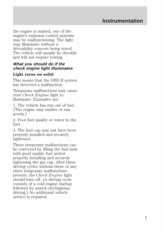
the engine is started, one of theengine’s emission control systemsmay be malfunctioning. The lightmay illuminate without adriveability concern being noted.The vehicle will usually be drivableand will not require towing.
What you should do if thecheck engine light illuminatesLight turns on solid:
This means that the OBD II systemhas detected a malfunction.
Temporary malfunctions may causeyour Check Engine light toilluminate. Examples are:
1. The vehicle has run out of fuel.(The engine may misfire or runpoorly.)
2. Poor fuel quality or water in thefuel.
3. The fuel cap may not have beenproperly installed and securelytightened.
These temporary malfunctions canbe corrected by filling the fuel tankwith good quality fuel and/orproperly installing and securelytightening the gas cap. After threedriving cycles without these or anyother temporary malfunctionspresent, the Check Engine lightshould turn off. (A driving cycleconsists of a cold engine startupfollowed by mixed city/highwaydriving.) No additional vehicleservice is required.
Instrumentation
7

If the Check Engine light remainson, have your vehicle serviced atthe first available opportunity.
Light is blinking:
Engine misfire is occurring whichcould damage your catalyticconverter. You should drive in amoderate fashion (avoid heavyacceleration and deceleration) andhave your vehicle serviced at thefirst available opportunity.
Under engine misfireconditions, excessive
exhaust temperatures coulddamage the catalytic converter,the fuel system, interior floorcoverings or other vehiclecomponents, possibly causing afire.
Air bag readiness
Momentarily illuminates when theignition is turned ON. If the lightfails to illuminate, continues toflash or remains on, have thesystem serviced immediately.
Safety belt
Momentarily illuminates when theignition is turned ON to remindyou to fasten your safety belts. Formore information, refer to theSeating and safety restraintschapter.
Instrumentation
8

Brake system warning
Momentarily illuminates when theignition is turned on and theengine is off. Also illuminates whenthe parking brake is engaged.Illumination after releasing theparking brake indicates low brakefluid level.
Anti-lock brake system (ABS)
Momentarily illuminates when theignition is turned on and theengine is off. If the light remainson, continues to flash or fails toilluminate, have the systemserviced immediately.
Turn signal
Illuminates when the left or rightturn signal or the hazard lights areturned on. If one or both of theindicators stay on continuously orflash faster, check for a burned-outturn signal bulb. Refer to Exteriorbulbs in the Maintenance andcare chapter.
High beams
Illuminates when the high beamheadlamps are turned on.
!BRAKE
ABS
Instrumentation
9
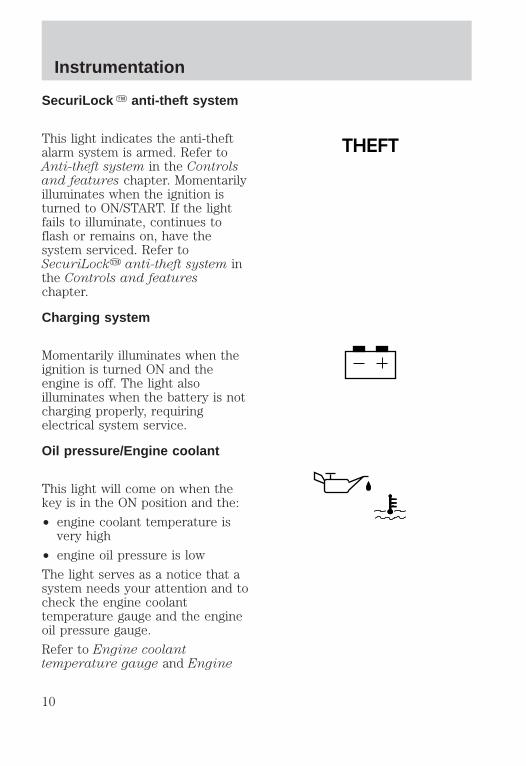
SecuriLock Y anti-theft system
This light indicates the anti-theftalarm system is armed. Refer toAnti-theft system in the Controlsand features chapter. Momentarilyilluminates when the ignition isturned to ON/START. If the lightfails to illuminate, continues toflash or remains on, have thesystem serviced. Refer toSecuriLocky anti-theft system inthe Controls and featureschapter.
Charging system
Momentarily illuminates when theignition is turned ON and theengine is off. The light alsoilluminates when the battery is notcharging properly, requiringelectrical system service.
Oil pressure/Engine coolant
This light will come on when thekey is in the ON position and the:
• engine coolant temperature isvery high
• engine oil pressure is low
The light serves as a notice that asystem needs your attention and tocheck the engine coolanttemperature gauge and the engineoil pressure gauge.
Refer to Engine coolanttemperature gauge and Engine
THEFT
Instrumentation
10

oil pressure gauge in this chapterfor more information.
Four wheel drive low(if equipped)
Illuminates when four-wheel drivelow is selected.
Four wheel drive indicator(if equipped)
Illuminates when 4x4 range isselected.
Automatic four wheel driveindicator (if equipped)
Illuminates when A4WD(automatic 4–wheel drive) isengaged.
Check air suspension
Illuminates momentarily when theignition is turned to the ONposition and the engine is OFF.The light also illuminates when theair suspension system requiresservicing.
For information on the airsuspension system, refer to theDriving chapter.
LOWRANGE
4x4
A4WD
CHECKSUSP
Instrumentation
11

Low washer fluid
Illuminates when the ignition isturned to ON and when thewindshield washer fluid is low.
Door ajar
Illuminates when the ignitionswitch is in the ON or STARTposition and any door is open.
Fuel reset
Illuminates when the ignition keyis turned to the ON position andthe fuel pump shut-off switch hasbeen triggered. For moreinformation, refer to Fuel pumpshut-off switch in the Roadsideemergencies chapter.
Safety belt warning chimeChimes to remind you to fastenyour safety belts.
For information on the safety beltwarning chime, refer to theSeating and safety restraintschapter.
Supplemental restraint system(SRS) warning chimeFor information on the SRSwarning chime, refer to theSeating and safety restraintschapter.
LOWWASH
DOORAJAR
FUELRESET
Instrumentation
12

Key-in-ignition warning chimeSounds when the key is left in theignition in the OFF/LOCK or ACCposition and either front door isopened.
Headlamps on warning chimeSounds when the headlamps orparking lamps are on, the ignitionis off (and the key is not in theignition) and either front door isopened.
GAUGES
Fuel gauge
Displays approximately how muchfuel is in the fuel tank (when thekey is in the ON position). Thefuel gauge may vary slightly whenthe vehicle is in motion. Theignition should be in the OFFposition while the vehicle is beingrefueled. When the gauge firstindicates empty, there is a smallamount of reserve fuel in the tank.When refueling the vehicle fromempty indication, the amount offuel that can be added will be less
FUELRESET
CHECKENGINE
LOWRANGE
4 X 4
ABSBRAKE
! + -
THEFT
LOWFUEL
DOORAJAR L
E
F
H
0
0 0 0 0RPM 1000X
0 0 0 0 0
MPH
20 km/h
40
6080 100
120
140
160
0 0
1
23
5
6
4
P R N 2 1
10
20
3040
50 6070
80
90
100
8C
18
H
D
CHECKSUSP
LOWWASH
A4WD
FUEL DOOR
E
F
Instrumentation
13

than the advertised capacity due tothe reserve fuel.
Speedometer
Indicates the current vehiclespeed.
Engine coolant temperaturegauge
Indicates the temperature of theengine coolant. At normaloperating temperature, the needleremains within the normal area(the area between the “H” and“C”). If it enters the red section,the engine is overheating. Stop thevehicle, switch off the ignition andlet the engine cool. Refer toEngine coolant in theMaintenance and care chapter.
Never remove the coolantrecovery cap while the
engine is running or hot.
This gauge indicates thetemperature of the engine coolant,not the coolant level. If the coolantis not at its proper level ormixture, the gauge indication willnot be accurate.
0
0 0 0 0
0 0 0 0 0
MPH
20 km/h
40
6080 100
120
140
160
010
20
3040
50 6070
80
90
100
H
C
Instrumentation
14

Odometer
Registers the total kilometers(miles) of the vehicle.
Trip odometer
Registers the kilometers (miles) ofindividual journeys. To reset,depress the control.
Tachometer
Indicates the engine speed inrevolutions per minute.
Driving with your tachometerpointer continuously at the top ofthe scale may damage the engine.
0
0 0 0 0
0 0 0 0 0
MPH
20 km/h
40
6080 100
120
140
160
010
20
3040
50 6070
80
90
100
0
0 0 0 0
0 0 0 0 0
MPH
20 km/h
40
6080 100
120
140
160
010
20
3040
50 6070
80
90
100
RPM 1000X0
1
23
5
6
4
FUEL DOOR
Instrumentation
15

Battery voltage gauge
This gauge shows the batteryvoltage when the ignition is in theON position. If the pointer movesand stays outside the normaloperating range (as indicated),have the vehicle’s electrical systemchecked as soon as possible.
Engine oil pressure gauge
This shows the engine oil pressurein the system. Sufficient pressureexists as long as the needleremains in the normal range (thearea between the “H” and “L”).
If the gauge indicates lowpressure, switch off the engineimmediately. Check the oil level.Add oil if needed (refer toChecking and adding engine oilin the Maintenance and carechapter). If the oil level is correct,have your vehicle checked at yourdealership or by a qualifiedtechnician.
TRIP COMPUTERThe trip computer tells you aboutthe condition of your vehiclethrough a constant monitor ofvehicle systems. You may selectdisplay features on the tripcomputer for a display of status.
The appearance of your vehicle’strip computer may differ
8
18
L
H
Instrumentation
16

depending on your vehicle’s optionpackage, but the functions are thesame.
The trip computer only workswhen the ignition is in the ONposition. Trip computer featuresfollow:
Selectable features
English/metric display
Press this control to change thetrip computer display from metricto English units. Press again tochange from English to metricunits.
Mode control
Each press of the MODE controlwill display a different feature asfollows:
Compass display. Refer toElectronic compass in theControls and features chapter formore information.
Fuel range. This displays theapproximate number of kilometers(miles) left to drive before the fueltank is empty. The indicateddistance to empty may beinaccurate:
1. with sustained, drastic changesin fuel economy (such as trailertowing), but will eventuallyrecover.
RESET
E/MMODE
MILES
TO EMPTY
RESET
E/MMODE
MILES
TO EMPTY
Instrumentation
17

2. if the vehicle is started whileparked on an incline.
3. if less than 30 liters (8 gallons)of fuel is added to the fuel tank.
The fuel range function will flashfor 5 seconds when you haveapproximately the followingamounts of fuel left before you runout:
• 80 km (50 miles)
• 40 km (25 miles)
• 16 km (10 miles)
Average fuel economy. Thedisplay will indicate the vehicle’saverage fuel economy in liters/100km (or miles/gallon) since lastreset.
• To reset the average fueleconomy:
1. Press the MODE controlrepeatedly until AVG F/ECON isdisplayed (no other display isresettable).
2. Press the E/M and MODEcontrols simultaneously.
Instantaneous fuel economy.The display will indicate theinstantaneous fuel economy ofyour running vehicle.
RESET
E/MMODE
MILESTO EMPTY
Instrumentation
18

Press the MODE control one finaltime to turn the trip computerdisplay off. RESET
E/MMODE
MILES
TO EMPTY
Instrumentation
19

HEADLAMP CONTROL
Rotate the headlamp control to thedesired position:
— OFF.
— Parking lamps on.
— Headlamps on.
Foglamp control (if equipped)
The headlamp control alsooperates the foglamps. Thefoglamps can be turned on onlywhen the headlamps are in the
position.
Pull headlamp control towards youto turn foglamps on. The foglampindicator light (located to theright of the control) will illuminate.
Daytime running light (Canadianvehicles only)The daytime running light systemturns the headlamps on, with areduced light output, when:
• the vehicle is running
• the parking brake is released
• the headlamp system is in theOFF position
PULLFOR
FOGP
PULLFOR
FOGP
Controls and features
20

The Daytime RunningLight (DRL) system will
not illuminate the tail lamps andparking lamps. Turn on yourheadlamps at dusk. Failure to doso may result in a collision.
PANEL DIMMER CONTROL
Use to adjust the brightness of theinstrument panel during headlightand parklamp operation.
• Rotate up to brighten.
• Rotate down to dim.
Use to control the dome lamps.
• Rotate all the way up to turn on.
• Rotate all the way down tooverride.
AUTOLAMP CONTROL
The autolamp system provideslight sensitive automatic on-offcontrol of the exterior lightsnormally controlled by theheadlamp control.
The autolamp system also keepsthe lights on for a preselectedperiod of time after the ignitionswitch is turned to OFF.
• To turn autolamps on, rotate thecontrol up. The preselected timelapse is adjustable up toapproximately three minutes bycontinuing to rotate the controlupward.
Controls and features
21

• To turn autolamps off, rotate thecontrol down until it clicks.
• A small LED illuminates next tothe autolamp control to indicatethat the headlamps have beenturned on by the autolamps.
• Foglamps are not controlled bythe autolamps. In order to turnon the foglamps, you must turnthe lamp switch to the
position and pull for fog.
REAR WINDOW DEFROSTER
The rear defroster control islocated on the instrument panel.
Press the defroster control to clearthe rear window of thin ice andfog.
• The small LED will illuminatewhen the defroster is activated.
The ignition must be in the ONposition to operate the rearwindow defroster.
The defroster turns offautomatically after 10 minutes orwhen the ignition is turned to theOFF position. To manually turn offthe defroster before ten minuteshave passed, push the controlagain.
Controls and features
22
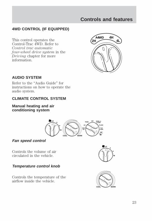
4WD CONTROL (IF EQUIPPED)
This control operates theControl-Trac 4WD. Refer toControl trac automaticfour-wheel drive system in theDriving chapter for moreinformation.
AUDIO SYSTEMRefer to the “Audio Guide” forinstructions on how to operate theaudio system.
CLIMATE CONTROL SYSTEM
Manual heating and airconditioning system
Fan speed control
Controls the volume of aircirculated in the vehicle.
Temperature control knob
Controls the temperature of theairflow inside the vehicle.
4H2H
A4WD4L
HI
COOL WARM
OFFPANEL
FLOOR
DEF
FLR& DEF
A/C
MAXA/C
PANEL &FLOOR
LO
HI
LO
COOL WARM
Controls and features
23

Mode selector controlControls the direction of theairflow to the inside of the vehicle.
The air conditioning compressorwill operate in all modes exceptPANEL and FLOOR. However, theair conditioning will only functionif the outside temperature is about10°C (50°F) or above.
Since the air conditioner removesconsiderable moisture from the airduring operation, it is normal ifclear water drips on the groundunder the air conditioner drainwhile the system is working andeven after you have stopped thevehicle.
Under normal conditions, yourvehicle’s climate control systemshould be left in any position otherthan MAX A/C or OFF when thevehicle is parked. This allows thevehicle to “breathe” through theoutside air inlet duct.
• MAX A/C-Uses recirculated airto cool the vehicle. MAX A/C isnoisier than A/C but moreeconomical and will cool theinside of the vehicle faster.Airflow will be from theinstrument panel registers. Thismode can also be used toprevent undesirable odors fromentering the vehicle.
• A/C-Uses outside air to cool the
OFFPANEL
A/C FLOOR
DEF
FLR& DEF
MAXA/C
PANEL &FLOOR
Controls and features
24

vehicle. It is quieter than MAXA/C but not as economical.Airflow will be from theinstrument panel registers.
• PANEL-Distributes outside airthrough the instrument panelregisters. However, the air willnot be cooled below the outsidetemperature because the airconditioning does not operate inthis mode.
• OFF-Outside air is shut out andthe fan will not operate. Forshort periods of time only, usethis mode to preventundesirable odors from enteringthe vehicle.
• PANEL & FLOOR-Distributesoutside air through theinstrument panel registers andthe floor ducts. Heating and airconditioning capabilities areprovided in this mode. Foradded customer comfort, whenthe temperature control knob isanywhere in between the fullhot and full cold positions, theair distributed through the floorducts will be slightly warmerthan the air sent to theinstrument panel registers.
• FLOOR-Allows for maximumheating by distributing outsideair through the floor ducts.However, the air will not becooled below the outsidetemperature because the airconditioning does not operate inthis mode.
Controls and features
25

• FLR & DEF-Distributes outsideair through the windshielddefroster ducts and the floorducts. Heating and airconditioning capabilities areprovided in this mode. Foradded customer comfort, the airdistributed through the floorducts will be slightly warmerthan the air sent to thewindshield defroster ducts. Ifthe temperature is about 10°C(50°F) or higher, the airconditioner will automaticallydehumidify the air to preventfogging.
• DEF -Distributes outsideair through the windshielddefroster ducts. It can be usedto clear ice or fog from thewindshield. If the temperature isabout 10°C (50°F) or higher, theair conditioner will automaticallydehumidify the air to preventfogging.
Operating tips• In humid weather, select DEF
before driving. This willprevent your windshield fromfogging. After a few minutes,select any desired position.
• To prevent humidity buildupinside the vehicle, don’t drivewith the climate control systemin the OFF position.
• Don’t put objects under thefront seat that will interfere withthe airflow to the back seats (ifequipped).
Controls and features
26

• Remove any snow, ice or leavesfrom the air intake area (at thebottom of the windshield underthe hood).
• If your vehicle has been parkedwith the windows closed duringhot weather, the air conditionerwill do a much faster job ofcooling if you drive for two orthree minutes with the windowsopen. This will force most of thehot, stale air out of the vehicle.Then operate your airconditioner as you wouldnormally.
• When placing objects on top ofyour instrument panel, becareful to not place them overthe defroster outlets. Theseobjects can block airflow andreduce your ability to seethrough your windshield. Also,avoid placing small objects ontop of your instrument panel.These objects can fall down intothe defroster outlets and blockairflow and possibly damageyour climate control system.
Controls and features
27

Rear console climate controls(if equipped)
Depending on the equipmentpackage of your vehicle, the rearconsole may not be equipped withrear console audio/climate controls.
Turn the air distribution control tothe desired airflow position.
The instrument panel climatecontrols must be on in order forthe rear climate control consolecontrols to work.
Turn the fan speed control to thedesired position.
Select for air to flow throughthese vents:
- VOLUME + MODE
SEEK MEMORY
- VOLUME + MODE
SEEK MEMORY
SEEK
– VOLUME + BAND
MEMORY
Controls and features
28

Select for air to flow throughthese vents:
Auxiliary A/C-heater controls(if equipped)
The auxiliary A/C-heater featureprovides increased capacity toquickly heat or cool the vehicle.Besides the driver’s overheadcontrol panel for the front seatoccupants, the second rowauxiliary A/C-heater controls allowthe rear passengers to control thetemperature in the rear of thevehicle through a second controlpanel above the second row.
SEEK
– VOLUME + BAND
MEMORY
Controls and features
29
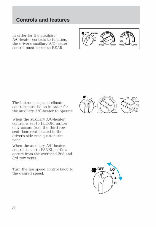
In order for the auxiliaryA/C-heater controls to function,the driver’s auxiliary A/C-heatercontrol must be set to REAR.
The instrument panel climatecontrols must be on in order forthe auxiliary A/C-heater to operate.
When the auxiliary A/C-heatercontrol is set to FLOOR, airflowonly occurs from the third rowseat floor vent located in thedriver’s side rear quarter trimpanel.
When the auxiliary A/C-heatercontrol is set to PANEL, airflowoccurs from the overhead 2nd and3rd row vents.
Turn the fan speed control knob tothe desired speed.
WARM PANEL FLOORCOOL
REAROFF
HI
HI
COOL WARM
OFFPANEL
FLOOR
DEF
FLR& DEF
PANEL &FLOOR
LO
LOOFF
HI
Controls and features
30

Turn the temperature control tothe desired temperature.
You can get warm or cool airthrough either the overheadregisters or floor vent by turningthe auxiliary mode selector:
• Far left for airflow to theoverhead registers.
• Far right for airflow to the rearfloor vent.
• Anywhere between PANEL andFLOOR to vary airflow betweenthe outlets.
WARMCOOL
HI
COOL WARM PANEL FLOOR
OFF LO
PANEL FLOOR
Controls and features
31
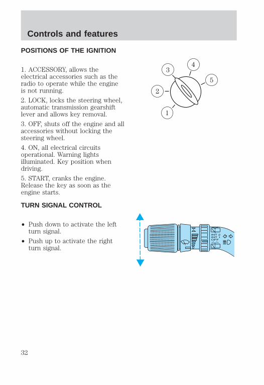
POSITIONS OF THE IGNITION
1. ACCESSORY, allows theelectrical accessories such as theradio to operate while the engineis not running.
2. LOCK, locks the steering wheel,automatic transmission gearshiftlever and allows key removal.
3. OFF, shuts off the engine and allaccessories without locking thesteering wheel.
4. ON, all electrical circuitsoperational. Warning lightsilluminated. Key position whendriving.
5. START, cranks the engine.Release the key as soon as theengine starts.
TURN SIGNAL CONTROL
• Push down to activate the leftturn signal.
• Push up to activate the rightturn signal.
3
1
2
5
4
Controls and features
32
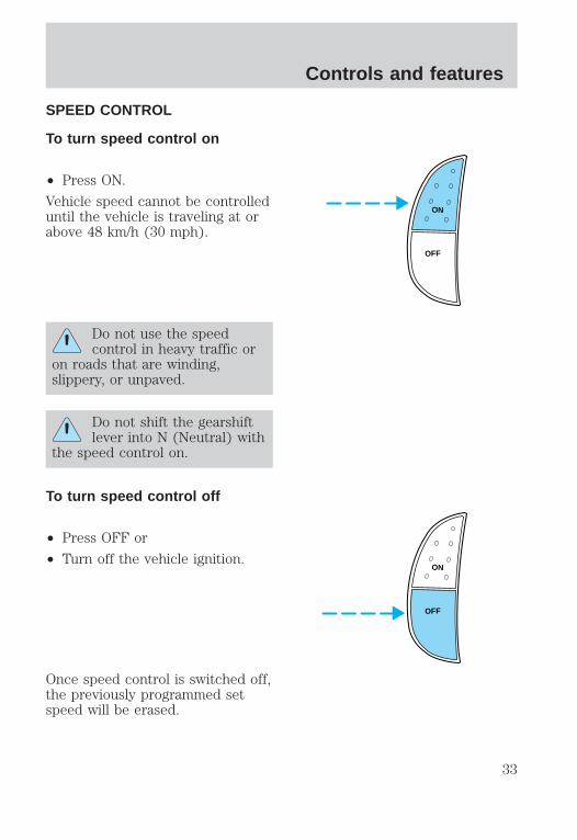
SPEED CONTROL
To turn speed control on
• Press ON.
Vehicle speed cannot be controlleduntil the vehicle is traveling at orabove 48 km/h (30 mph).
Do not use the speedcontrol in heavy traffic or
on roads that are winding,slippery, or unpaved.
Do not shift the gearshiftlever into N (Neutral) with
the speed control on.
To turn speed control off
• Press OFF or
• Turn off the vehicle ignition.
Once speed control is switched off,the previously programmed setspeed will be erased.
ON
OFF
ON
OFF
Controls and features
33

To set a speed
• Press SET ACC/SET ACCEL.For speed control to operate,the speed control must be ONand the vehicle speed must begreater than 48 km/h (30 mph).
If you drive up or down a steephill, your vehicle speed may varymomentarily slower or faster thanthe set speed. This is normal.
Speed control cannot reduce thevehicle speed if it increases abovethe set speed on a downhill. Ifyour vehicle speed is faster thanthe set speed while driving on adownhill, you may want to shift tothe next lower gear or apply thebrakes to reduce your vehiclespeed.
If your vehicle slows down morethan 16 km/h (10 mph) below yourset speed on an uphill, your speedcontrol will disengage. This isnormal. PressingRES/RSM/RESUME will re-engageit.
Do not use the speedcontrol in heavy traffic or
on roads that are winding,slippery, or unpaved.
RES
SETACCEL
COAST
Controls and features
34
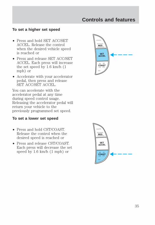
To set a higher set speed
• Press and hold SET ACC/SETACCEL. Release the controlwhen the desired vehicle speedis reached or
• Press and release SET ACC/SETACCEL. Each press will increasethe set speed by 1.6 km/h (1mph) or
• Accelerate with your acceleratorpedal, then press and releaseSET ACC/SET ACCEL.
You can accelerate with theaccelerator pedal at any timeduring speed control usage.Releasing the accelerator pedal willreturn your vehicle to thepreviously programmed set speed.
To set a lower set speed
• Press and hold CST/COAST.Release the control when thedesired speed is reached or
• Press and release CST/COAST.Each press will decrease the setspeed by 1.6 km/h (1 mph) or
RES
SETACCEL
COAST
RES
SETACCEL
COAST
Controls and features
35

• Depress the brake pedal. Whenthe desired vehicle speed isreached, press SET ACC/SETACCEL.
To disengage speed control
• Depress the brake pedal.
Disengaging the speed control willnot erase the previouslyprogrammed set speed.
Pressing OFF will erase thepreviously programmed set speed.
RES
SETACCEL
COAST
ON
OFF
Controls and features
36

To return to a previously setspeed
• Press RES/RSM/RESUME. ForRES/RSM/RESUME to operate,the vehicle speed must be fasterthan 48 km/h (30 mph).
TILT STEERING
Pull the tilt steering control towardyou to move the steering wheel upor down. Hold the control whileadjusting the wheel to the desiredposition, then release the control.
Never adjust the steeringwheel when the vehicle is
moving.
RES
SETACCEL
COAST
Controls and features
37

HAZARD FLASHERFor information on the hazardflasher control, refer to Hazardlights control in the Roadsideemergencies chapter.
WINDSHIELD WIPER/WASHERCONTROLS
Rotate the windshield wipercontrol to the desired interval, lowor high speed position.
The bars of varying length are forintermittent wipers. When in thisposition rotate the control upwardfor fast intervals and downward forslow intervals.
Push the control on the end of thestalk to activate washer. Push andhold for a longer wash cycle.
Rear window wiper/washercontrols
Rotate (and hold as desired) therear wiper/washer control to either
position.
From either position, the controlwill automatically return to theINT2 or OFF position.
For rear wiper operation, rotatethe rear window wiper and washercontrol to the desired position.Select:
INT 2 — One second interval rearwiper.
Controls and features
38

INT 1 — Ten second interval rearwiper.
OFF — Rear wiper and washer off.
Speed dependent wipersWhen the windshield wiper controlis set on the intermittent settings,speed-sensitive front wipersautomatically adjust as thevehicle’s speed increases.
HIGH BEAMS
Push forward to activate.
FLASH TO PASS
Pull back to activate and release todeactivate.
OVERDRIVE CONTROL
Activating overdrive(Overdrive) is the normal drive
position for the best fuel economy.
The overdrive function allowsautomatic upshifts to second, thirdand forth gear.
Controls and features
39

Deactivating overdrive
Press the transmission control atthe end of the gearshift lever. Thetransmission control indicator lightTCIL (OFF) will illuminate on theend of the gearshift lever
The transmission will operate ingears one through three. To returnto normal overdrive mode, pressthe transmission control again. TheTCIL (OFF) will no longer beilluminated.
When you shut off and re-startyour vehicle, the transmission willautomatically return to normal
(Overdrive) mode.
OVERHEAD CONSOLEThe appearance of your vehicle’soverhead console will varyaccording to your option package.
Forward storage bin(if equipped)
Press the release control to openthe storage compartment. Thedoor will open slightly and can bemoved to full open.
The storage compartment may beused to secure sunglasses or asimilar object.
OVERDRIVE
OVERDRIVE OFF
Controls and features
40
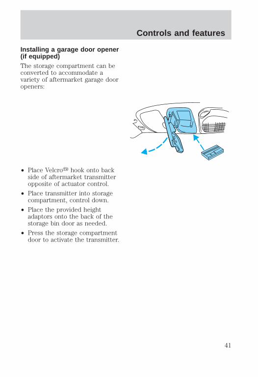
Installing a garage door opener(if equipped)The storage compartment can beconverted to accommodate avariety of aftermarket garage dooropeners:
• Place Velcroy hook onto backside of aftermarket transmitteropposite of actuator control.
• Place transmitter into storagecompartment, control down.
• Place the provided heightadaptors onto the back of thestorage bin door as needed.
• Press the storage compartmentdoor to activate the transmitter.
Controls and features
41

One-touch moon roof(if equipped)
• Press and release the rearportion of the moon roof controlto open.
• Press and hold (as desired) thefront portion of the moon roofcontrol to close.
• To halt motion at any pointduring one-touch opening, pressthe control a second time.
• The moon roof has a slidingshade that can be manuallyopened or closed when the glasspanel is shut.
• To close the shade, pull ittoward the front of the vehicle.
Do not let children playwith the moon roof. They
may seriously hurt themselves.
Message centerFor information on the messagecenter, refer to Electronicmessage center in theInstrumentation chapter.
Electronic compass(if equipped)The compass reading may beaffected when you drive near largebuildings, bridges, power lines andpowerful broadcast antenna.Magnetic or metallic objects placedin, on or near the vehicle may alsoaffect compass accuracy.
VENTVENT ROOF
Controls and features
42

Usually, when something affectsthe compass readings, the compasswill correct itself after a few daysof operating your vehicle in normalconditions. If the compass stillappears to be inaccurate, a manualcalibration may be necessary. Referto Compass calibrationadjustment.
Most geographic areas (zones)have a magnetic north compasspoint that varies slightly from thenortherly direction on maps. Thisvariation is four degrees betweenadjacent zones and will becomenoticeable as the vehicle crossesmultiple zones. A correct zonesetting will eliminate this error.Refer to Compass zoneadjustment.
Compass zone adjustment
1. Determine which magnetic zoneyou are in for your geographiclocation by referring to the zonemap.
1
2
3
4
56
7 8 9
10
11
12
13
1415
Controls and features
43

2. Locate the compass modulemounted at the base of the mirror.
3. Turn ignition to the ON position.
4. Insert an appropriate diameterrod (paperclip) into the small holeunderneath the compass moduleand gently press the switch for 1to 2 seconds until ZONE and thecurrent zone setting is displayedon the trip computer.
5. Release the switch, then slowlypress down again. Press the switchrepeatedly until the correct zonesetting for your geographiclocation is displayed on the tripcomputer.
6. To exit the zone setting mode,release pressure from the switchfor greater than two seconds.
Compass calibration adjustmentPerform this adjustment in anopen area free from steelstructures and high voltage lines.
For optimum calibration, turn offall electrical accessories (heater/airconditioning, wipers, etc.) andmake sure all vehicle doors areshut.
1. Start the vehicle.
Controls and features
44

2. Locate the compass modulemounted on the base of the mirror.
3. Insert an appropriate diameterrod (paperclip) into the switchaccess hole underneath thecompass module.
4. Gently press the switch for 2 to4 seconds until CAL and adirection are displayed on the tripcomputer. (To exit CAL modebefore performing a compassadjustment, turn the ignition OFF.)
5. Release pressure from theswitch.
6. Slowly drive the vehicle in acircle (less than 5 km/h [3 mph])until the CAL indicator turns off.This will take up to five circles tocomplete calibration.
7. The compass is now calibrated.
Power quarter rear windows(if equipped)
Press the portion of the VENTcontrol to open the power rearquarter windows.
Press the portion of the VENTcontrol to close the power rearquarter windows. RESET
VENT VENT
MODE E/M
Controls and features
45
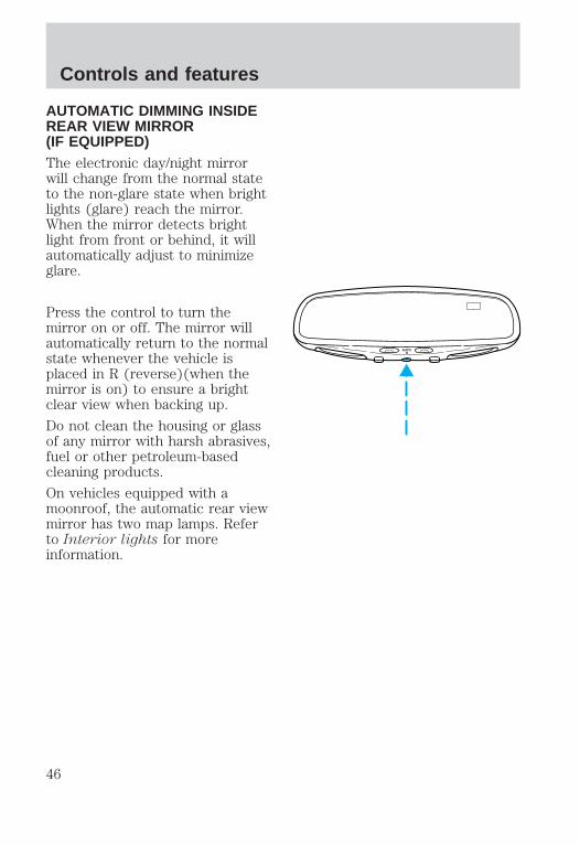
AUTOMATIC DIMMING INSIDEREAR VIEW MIRROR(IF EQUIPPED)The electronic day/night mirrorwill change from the normal stateto the non-glare state when brightlights (glare) reach the mirror.When the mirror detects brightlight from front or behind, it willautomatically adjust to minimizeglare.
Press the control to turn themirror on or off. The mirror willautomatically return to the normalstate whenever the vehicle isplaced in R (reverse)(when themirror is on) to ensure a brightclear view when backing up.
Do not clean the housing or glassof any mirror with harsh abrasives,fuel or other petroleum-basedcleaning products.
On vehicles equipped with amoonroof, the automatic rear viewmirror has two map lamps. Referto Interior lights for moreinformation.
AUTO
Controls and features
46

POWER WINDOWSPress and hold the rocker switchesto open and close windows.
• Press the top portion of therocker switch to close.
• Press the bottom portion of therocker switch to open.
One touch down
• Press AUTO and release quickly.The window will open fully.Depress again to stop windowoperation.
AUTO
AUTO
AUTO
Controls and features
47

Window lock
The window lock feature allowsonly the driver to operate thepower windows.
Accessory delayWith accessory delay, the windowswitches may be used for up to tenminutes after the ignition switch isturned to the OFF position or untileither door is opened.
POWER DOOR LOCKS
Press U to unlock all doors and Lto lock all doors.
AutolockThis feature automatically locks alldoors when:
• all vehicle doors, liftgate andliftgate window are closed
• the ignition switch is in the ONposition
• you shift into or through R(Reverse)
• the brake pedal is released.
WINDOW LOCK
U L
Controls and features
48

RelockThe autolock feature repeats when:
• any door is opened and closed
• the brake pedal is released.
Deactivating/activating theautolock featureBefore following the procedure,make sure that the ignition is OFFand all vehicle doors and theliftgate window are closed.
You must complete steps 1-5within 30 seconds or theprocedure will have to berepeated. If the procedure needsto be repeated, you must wait 30seconds.
1. Turn the ignition key to ON.
2. Press the power door unlockcontrol three times.
3. Turn the ignition key from ONto OFF.
4. Press the power door unlockcontrol three times.
5. Turn the ignition back to ON.The horn will chirp.
6. Press the unlock control, thenpress the lock control. The hornwill chirp once if autolock wasdeactivated or twice (one shortand one long chirp) if autolock wasactivated.
7. Turn the ignition to OFF. Thehorn will chirp once to confirm theprocedure is complete.
Controls and features
49

CHILDPROOF DOOR LOCKS
When these locks are set, the reardoors cannot be opened from theinside. The rear doors can beopened from the outside when thedoors are unlocked.
The childproof locks are located onrear edge of each rear door andmust be set separately for eachdoor. Setting the lock for one doorwill not automatically set the lockfor both doors.
Move lock control up to engage thelock. Move control down todisengage childproof locks.
POWER SIDE VIEW MIRRORSTo adjust your mirrors:
1. Select L to adjust the left mirroror R to adjust the right mirror.
2. Move the control in thedirection you wish to tilt themirror.
MIRRORS
L R
MIRRORS
L R
Controls and features
50

3. Return to the center position tolock mirrors in place.
Heated outside mirrors
Both mirrors are heatedautomatically to remove ice, mistand fog when the rear windowdefrost is activated.
Do not remove ice from themirrors with a scraper or attemptto readjust the mirror glass if it isfrozen in place. These actionscould cause damage to the glassand mirrors.
Signal mirrors (if equipped)
If your vehicle is equipped withsignal mirrors, the word “signal” islocated at the top of the right andleft side view mirrors.
When the turn signal is activated,the appropriate mirror will show ablinking red arrow.
The arrow provides an additionalwarning to other drivers that yourvehicle is about to turn. Driver andpassengers seated inside thevehicle cannot see the arrow.
CENTER CONSOLEYour vehicle may be equipped witha variety of console features. Theseinclude:
• utility compartment
• cupholders
• coin holder slots
Signal
Controls and features
51

• tissue box holder
• compact disc changer
Use only soft cups in thecupholder. Hard objects
can injure you in a collision.
The auxiliary power point islocated on the instrument panel.
Do not plug optional electricalaccessories into the cigarettelighter. Use the powerpoint.
COMPACT DISC CHANGER(IF EQUIPPED)The compact disc changer islocated inside the front centerconsole.
For information on the compactdisc changer, refer to the “AudioGuide”.
Controls and features
52

POSITIVE RETENTION FLOORMAT (IF EQUIPPED)
Position the floor mat so that theeyelet is over the pointed end ofthe retention post and rotateforward to lock in. Make sure thatthe mat does not interfere with theoperation of the accelerator or thebrake pedal. To remove the floormat, reverse the installationprocedure.
LIFTGATE
To open the rear window, turn theliftgate handle to the right.
To open the liftgate, turn theliftgate handle to the left.
• Do not open the liftgate orliftgate glass in a garage orother enclosed area with a lowceiling. If the liftgate glass israised and the liftgate is alsoopened, both liftgate and glasscould be damaged against a lowceiling.
• Do not leave the liftgate orliftgate glass open while driving.Doing so could cause seriousdamage to the liftgate and itscomponents as well as allowingcarbon monoxide to enter thevehicle.
DOOR GLASS
Controls and features
53
Make sure that the liftgatedoor and/or window are
closed to prevent exhaust fumesfrom being drawn into thevehicle. This will also preventpassengers and cargo from fallingout. If you must drive with theliftgate door or window open,keep the vents open so outsideair comes into the vehicle.
SECURILOCKY ANTI-THEFTSYSTEMYour vehicle is equipped with acoded-key anti-theft system. Onlythe correct key will be able to startyour vehicle. If your keys are lostor stolen, you must take yourvehicle to a Ford/Lincoln-Mercurydealership for re-programming.
Programming additional keysIf you need additional keyselectronically coded for yourvehicle, spares can be purchased(a maximum of 16 keys can beprogrammed). To program a newkey, perform the followingprocedure:
1. With the coded key in theignition, turn the ignition from ONto OFF.
2. Within 15 seconds of turningignition off, insert the new codedkey into the ignition and turn itfrom OFF to ON or START. Ifsuccessful, the THEFT indicator
Controls and features
54

light will illuminate for twoseconds. Repeat procedure for allnew keys.
If key coding fails, the THEFTindicator light will flash.
Coding failure can be caused byany of the following:
• The new key was not insertedinto the ignition within 15seconds.
• 16 keys have already beenprogrammed.
• The new key does not have anelectronic code.
REMOTE ENTRY SYSTEMThe remote entry system allowsyou to lock or unlock all vehicledoors without a key.
The remote entry features onlyoperate with the ignition in theOFF position.
Unlocking the doors
Press this control to unlock thedriver door. The interior lamps andrunning board lamps (if equipped)will illuminate.
Press the control a second timewithin five seconds to unlock alldoors.
Controls and features
55

Locking the doors
Press this control to lock all doors.
To confirm all doors are closed andlocked, press the control a secondtime within five seconds. Thedoors will lock again, the horn willchirp and the lamps will flash.
If any of the doors are ajar, thehorn will make two quick chirps,reminding you to properly close alldoors.
Sounding a panic alarm
Press this control to activate thealarm.
To deactivate the alarm, press thecontrol again or turn the ignitionto ACC or ON.
This device complies with part 15of the FCC rules and with RS-210of Industry Canada. Operation issubject to the following twoconditions: (1) This device maynot cause harmful interference,and (2) This device must acceptany interference received,including interference that maycause undesired operation.
Changes or modifications notexpressly approved by theparty responsible forcompliance could void theuser’s authority to operate theequipment.
Controls and features
56

Replacing the batteriesThe transmitter is powered by onecoin type three-volt lithium batteryCR2032 or equivalent. Typicaloperating range will allow you tobe up to 10 meters (33 feet) awayfrom your vehicle. A decrease inoperating range can be caused by:
• battery weakness due to timeand use
• weather conditions
• nearby radio towers
• structures around the vehicle
• other vehicles parked next tothe vehicle
To replace the battery:
1. Twist a thin coin between thetwo halves of the transmitter nearthe key ring. DO NOT TAKE THEFRONT PART OF THETRANSMITTER APART.
2. Place the positive (+) side ofnew battery in the sameorientation. Refer to the diagraminside the transmitter unit.
3. Snap the two halves backtogether.
Controls and features
57

Replacing lost transmitters
Take all your vehicle’s transmittersto your dealer for reprogrammingif:
• a transmitter is lost or
• you want to purchase additionaltransmitters (up to four may beprogrammed).
To reprogram the transmitters,place the key in the ignition andswitch from OFF to ON eight timesin rapid succession within 10seconds. After doors lock/unlock,press any button on alltransmitters (up to four). Whencompleted, switch the ignition toOFF.
All transmitters must beprogrammed at the same time.
Illuminated entryThe interior lamps and the runningboard lights illuminate when theremote entry system is used tounlock the door(s) or sound thepersonal alarm.
The system automatically turns offafter 25 seconds or when theignition is turned to the RUNposition. The dome lamp switch (ifequipped) must not be set to theOFF position for the illuminatedentry system to operate.
The inside lights will not turn offif:
• they have been turned on withthe dimmer control or
Controls and features
58

• any door is open.
Battery saver will shut off theinterior lamps 40 minutes after thelast door is closed.
Controls and features
59

SEATING
Using the manual lumbarsupport
Turn the lumbar support controlcounterclockwise to increasefirmness.
Turn the lumbar support controlclockwise to increase softness.
Front seats
Never adjust the driver’sseat or seatback when the
vehicle is moving.
Do not pile cargo higherthan the seatbacks to
avoid injuring people in acollision or sudden stop.
Always drive and ride withyour seatback upright and
the lap belt snug and low acrossthe hips.
Seating and safety restraints
60

Lift handle to move seat forwardor backward.
Pull lever up to adjust seatback.
Using the armrest (if equipped)
Pull the strap to move the armrestdown.
To move the armrest up, lift ituntil it latches in the uprightposition.
Adjusting the front power seat(if equipped)
Never adjust the driver’sseat or seatback when the
vehicle is moving.
Seating and safety restraints
61

Do not pile cargo higherthan the seatbacks to
avoid injuring people in acollision or sudden stop.
Always drive and ride withyour seatback upright and
the lap belt snug and low acrossthe hips.
Press to raise or lower the frontportion of the seat cushion.
Press to raise or lower the rearportion of the seat cushion.
Press the control to move the seatforward, backward, up or down.
Seating and safety restraints
62

REAR SEATS
Head restraints
Push or pull the head rests to thedesired position.
Rear folding bench seat(if equipped)
Folding down the rear seats
Ensure that no objects such asbooks, purses or briefcases are onthe floor in front of the second rowseats before folding them down.
Move front passenger seat forwardso that the second row seat headrest clears the front seat.
For assistance, refer to the labellocated on the lower position ofthe opening.
1. Locate handle below the seatcushion near the bottom of thedoor side cushion (this handle ismarked “A”).
2. Lift the handle and push theseatback toward the front of thevehicle.
Seating and safety restraints
63

3. Press the green control on theseatback to release the closeoutpanel. Rotate the panel to closeoutthe space in the floor.
4. Once the second row seats arein the down position, the frontseats may be readjusted.
Returning the seat to upright
Always latch the vehicleseat to the floor, whether
the seat is occupied or empty. Ifnot latched, the seat may causeinjury during a sudden stop.
1. Rotate the closeout panel ontothe seatback and press the blackcontrol (adjacent to the greencontrol) to lock.
2. Locate and lift the handlemarked “A”.
3. Pull on the seatback while liftingthe handle to lift the seat into theupright position.
Seating and safety restraints
64

Reclining the seatback
Locate the lever at the bottom ofthe seatback marked “1”. Pull thelever upwards to recline theseatback.
Third row seat (if equipped)The third row seat is equippedwith combination lap and shoulderbelts in the outboard seatingpositions and a manual adjusttongue lap belt in the centerseating position. For informationon the proper operation of thesafety restraints, refer to SafetyRestraints in this chapter.
The third row seat may beremoved from the vehicle foradditional cargo space.
Seating and safety restraints
65

Accessing the third row seat
Your vehicle is equipped with aneasy entry second row seat featurewhich allows ready access to thethird row seat. You may enter thethird row seat:
• through the passenger side reardoor if your vehicle has asecond row bench seat
• through either rear door if yourvehicle has second row bucketseats
Ensure that the second row seat isin the upright position in order toachieve optimum access to thethird row.
To minimize the risk of personalinjury, the third row seat shouldnot be left in the forward, stowedposition while the vehicle is inmotion. Please ensure that the seatis in the upright, fully latchedposition before putting the vehiclein motion.
1. Locate the lever at the bottomof the seatback marked “1”.
2. Press down on the front of lever“1” while pressing the seatbackdown onto the cushion.
3. Locate and lift the lever marked“2” while rotating the seat towardthe front row seat.
4. After entering the seat, reversethis procedure; ensure that thelatch tub and surrounding areasare clear.
Seating and safety restraints
66
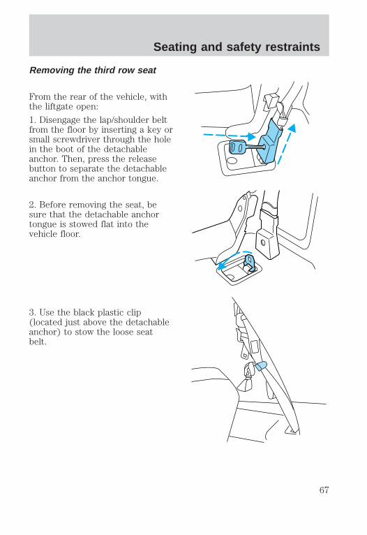
Removing the third row seat
From the rear of the vehicle, withthe liftgate open:
1. Disengage the lap/shoulder beltfrom the floor by inserting a key orsmall screwdriver through the holein the boot of the detachableanchor. Then, press the releasebutton to separate the detachableanchor from the anchor tongue.
2. Before removing the seat, besure that the detachable anchortongue is stowed flat into thevehicle floor.
3. Use the black plastic clip(located just above the detachableanchor) to stow the loose seatbelt.
Seating and safety restraints
67

• Pull the seat release leverlocated on the lower right sideof the seatback while pushingthe seatback down into the seatcushion.
• The seatback will latch onto thecushion.
4. Lift the seat release bar locatedat the center of the seat near thefloor to release the floor latches.
5. While pulling up on the releasebar, lift the seat up and out of thefloor tubs.
6. With assistance, lift the seat outof the vehicle.
Installing the third row seat
Always latch the vehicleseat to the floor, whether
the seat is occupied or empty. Ifnot latched, the seat may causeinjury during a sudden stop.
When reinstalling a rearseat in your vehicle it must
be placed in its original position.Improper installation of the seatwill prevent correct use of thesafety belts and could increasethe risk of injury. Refer to thewarning label on the seat belt.
Seating and safety restraints
68

Before installing your third rowseat, ensure that the detachableanchor tongues are stowed into thefloor and the loose belts are storedout of the way. For properlatching, ensure that the floor tubsare clear of debris.
From the rear of the vehicle, withthe liftgate open:
1. With assistance, lift the seat intothe rear of the vehicle and guidethe seat positioners over the frontpins of the floor tubs.
2. Guide the positioners aroundeach pin and lower the seat.
• When the rear of the seat is10–13 cm (4–5 in) above therear pins, let the seat drop. Thiswill ensure that the seat willproperly latch into the floor.
3. Locate the seat belt anchortongue in the plastic housing onthe floor.
4. Disconnect the detachableanchor from its stowage locationand connect it to the anchortongue (making sure that the labelon the detachable anchor ispointing toward the outside of thevehicle (left side) and that thebelts are not twisted or jammed).
5. Insert the seat detachableanchor into detachable anchortongue until you hear a “click” andfeel the latch engage.
6. Push up on the seat to verifythat it is latched into the floor.
Seating and safety restraints
69
7. Verify that the safety belts canmove freely on either side of theseat.
SAFETY RESTRAINTS
Safety restraints precautions
Always drive and ride withyour seatback upright and
the lap belt snug and low acrossthe hips.
To prevent the risk ofinjury, make sure children
sit where they can be properlyrestrained.
Never let a passenger holda child on his or her lap
while the vehicle is moving. Thepassenger cannot protect thechild from injury in a collision.
All occupants of thevehicle, including the
driver, should always wear theirsafety belts.
Seating and safety restraints
70

It is extremely dangerousto ride in a cargo area,
inside or outside of a vehicle. Ina collision, people riding in theseareas are more likely to beseriously injured or killed. Do notallow people to ride in any areaof your vehicle that is notequipped with seats and safetybelts. Be sure everyone in yourvehicle is in a seat and using asafety belt properly.
Each seating position inyour vehicle has a specific
safety belt assembly which ismade up of one buckle and onetongue that are designed to beused as a pair. 1) Use theshoulder belt on the outsideshoulder only. Never wear theshoulder belt under the arm. 2)Never swing it around your neckover the inside shoulder. 3)Never use a single belt for morethan one person.
Combination lap and shoulderbelts
1. To fasten, insert the tongue intothe slot in the buckle.
Seating and safety restraints
71

2. To unfasten, push the redrelease button and remove thetongue from the buckle.
The front and rear outboard safetyrestraints in the vehicle arecombination lap and shoulderbelts. The front and rear seatpassenger outboard safety beltshave two types of locking modesdescribed below:
Vehicle sensitive modeThe vehicle sensitive mode is thenormal retractor mode, allowingfree shoulder belt lengthadjustment to your movements andlocking in response to vehiclemovement. For example, if thedriver brakes suddenly or turns acorner sharply, or the vehiclereceives an impact of 8 km/h(5 mph) or more, the combinationsafety belts will lock to helpreduce forward movement of thedriver and passengers.
Automatic locking modeIn this mode, the shoulder belt isautomatically pre-locked. The beltwill still retract to remove anyslack in the shoulder belt.
The automatic locking mode is notavailable on the driver safety belt.
Seating and safety restraints
72

When to use the automaticlocking mode• When a tight lap/shoulder fit is
desired.
• Anytime a child safety seat isinstalled in the vehicle. Refer toSafety Restraints for Childrenor Safety Seats for Childrenlater in this chapter.
How to use the automaticlocking mode
• Buckle the combination lap andshoulder belt.
• Grasp the shoulder portion andpull downward until the entirebelt is extracted.
• Allow the belt to retract. As thebelt retracts, you will hear a
Seating and safety restraints
73
clicking sound. This indicatesthe safety belt is now in theautomatic locking mode.
How to disengage the automaticlocking modeDisconnect the combinationlap/shoulder belt and allow it toretract completely to disengage theautomatic locking mode andactivate the vehicle sensitive(emergency) locking mode.
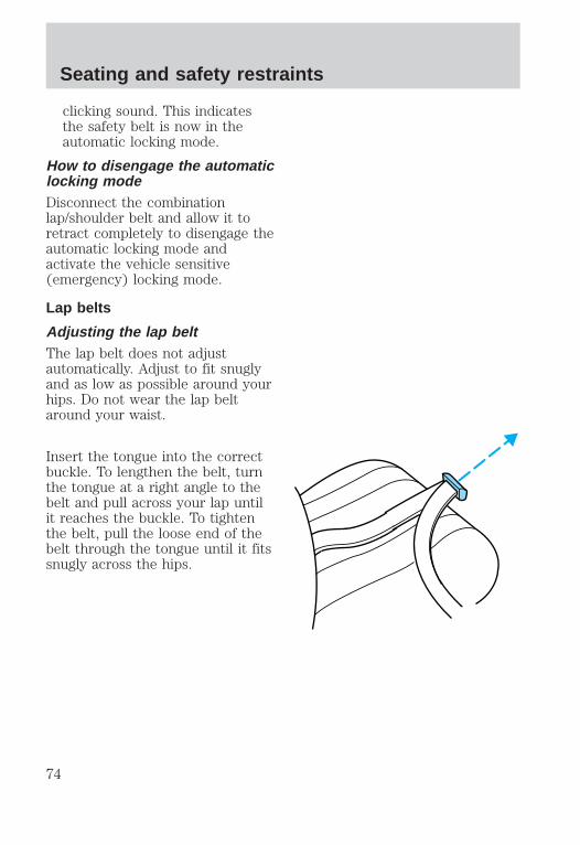
Lap belts
Adjusting the lap beltThe lap belt does not adjustautomatically. Adjust to fit snuglyand as low as possible around yourhips. Do not wear the lap beltaround your waist.
Insert the tongue into the correctbuckle. To lengthen the belt, turnthe tongue at a right angle to thebelt and pull across your lap untilit reaches the buckle. To tightenthe belt, pull the loose end of thebelt through the tongue until it fitssnugly across the hips.
Seating and safety restraints
74
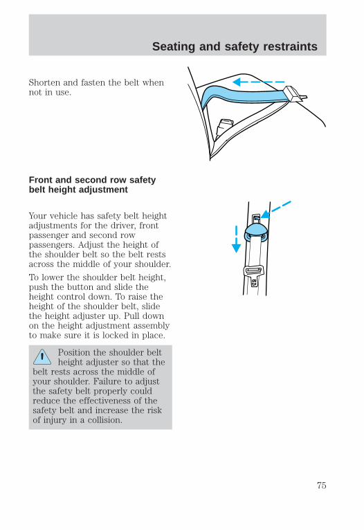
Shorten and fasten the belt whennot in use.
Front and second row safetybelt height adjustment
Your vehicle has safety belt heightadjustments for the driver, frontpassenger and second rowpassengers. Adjust the height ofthe shoulder belt so the belt restsacross the middle of your shoulder.
To lower the shoulder belt height,push the button and slide theheight control down. To raise theheight of the shoulder belt, slidethe height adjuster up. Pull downon the height adjustment assemblyto make sure it is locked in place.
Position the shoulder beltheight adjuster so that the
belt rests across the middle ofyour shoulder. Failure to adjustthe safety belt properly couldreduce the effectiveness of thesafety belt and increase the riskof injury in a collision.
Seating and safety restraints
75

Safety belt extension assemblyIf the safety belt assembly is tooshort, even when fully extended,20 cm (8 inches) can be added tothe safety belt assembly by addinga safety belt extension assembly(part number 611C22). Safety beltextension assemblies can beobtained from your dealer at nocost.
Use only extensions manufacturedby the same supplier as the safetybelt. Manufacturer identification islocated at the end of the webbingon the label. Also, use the safetybelt extension only if the safetybelt is too short for you when fullyextended. Do not use extensionsto change the fit of the shoulderbelt across the torso.
Safety belt warning light andindicator chimeThe seat belt warning lightilluminates in the instrumentcluster and a chime sounds toremind the occupants to fastentheir safety belts.
Seating and safety restraints
76

Conditions of operation
If... Then...
The driver’s safety belt is notbuckled before the ignition keyis turned to ON...
The safety belt warning lightilluminates for one to two minutes andthe warning chime sounds for four toeight seconds.
The driver’s safety belt isbuckled while the indicatorlight is illuminated and thewarning chime is sounding...
The safety belt warning light turns off.
The driver’s safety belt isbuckled before the ignition keyis turned to ON...
The safety belt warning light remainsoff.
Safety belt maintenanceCheck the safety belt systemsperiodically to make sure theywork properly and are notdamaged. Check the safety belts tomake sure there are no nicks,wears or cuts. All safety beltassemblies, including retractors,buckles, front seat belt buckleassemblies (slide bar)(ifequipped), shoulder belt heightadjusters (if equipped), childsafety seat tether bracketassemblies (if equipped), andattaching hardware, should beinspected after a collision. Fordrecommends that all safety beltassemblies used in vehiclesinvolved in a collision be replaced.However, if the collision was minorand a qualified technician findsthat the belts do not show damageand continue to operate properly,they do not need to be replaced.
Seating and safety restraints
77
Safety belt assemblies not in useduring a collision should also beinspected and replaced if eitherdamage or improper operation isnoted.
Failure to replace thesafety belt assembly under
the above conditions could resultin severe personal injuries in theevent of a collision.
Refer to Cleaning andmaintaining the safety belts inthe Maintenance and caresection.
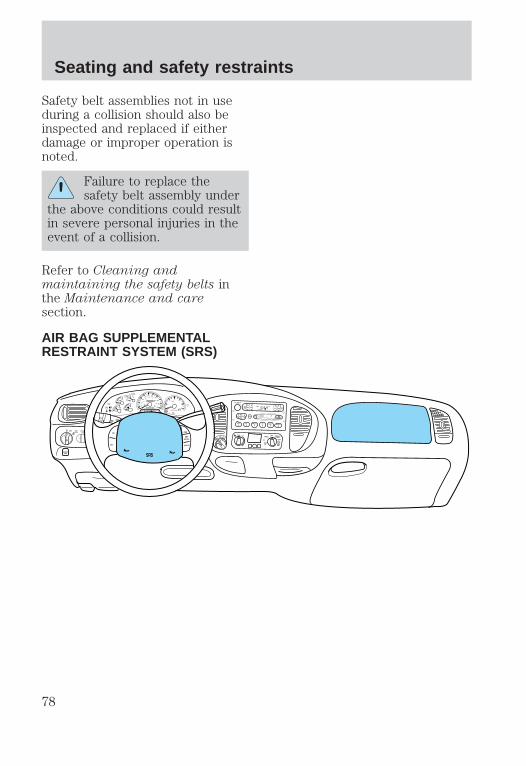
AIR BAG SUPPLEMENTALRESTRAINT SYSTEM (SRS)
FOR
SCAN EJ
REW FF SIDE 1-2 COMP SHUFFLE
TAPE CDDISCS
BASS TREB BAL FADE AUTOSET
VOL - PUSH ON
SEEKTUNE
AMFM
1 2 3 4 5 6
fw DOLBY B NR
FM1 ST
DOORAJAR
BRAKE
F
E
H
H
18
8
20
10
30
4050 60
70
80
90
100
20
40
60
80 100
120
140
160
MPH km/h0 0
0 0 0 0 0 0
0
1
2
P R N 2 1RPMx1000
CHECK
ENGINE
THEFT
34
5
6
CHECK
SUSP
LOWFUEL
ABS
P PULL
FOGPANEL
DIM
4HA4WD
4L FLOOR
PANEL
LO
HI
COOL WARM
DEF
FLR&DEF
PANEL &FLOOR
OFFPANEL
LO
HI
FLR&DEF
PANEL &FLOOR
OFF
MAXAC
AC FLOOR
FAN
OVERDRIVE
SRS
ON
OFF
RES
SETACCEL
COAST
Seating and safety restraints
78

Important supplementalrestraint system (SRS)precautions
The supplemental restraint systemis designed to:
• work with the safety belt toprotect the driver and rightfront passenger
• reduce certain upper bodyinjuries
Failure to follow theseinstructions will affect the
performance of the safety beltsand increase the risk of personalinjury.
The right front passengerair bag is not designed to
restrain occupants in the centerfront seating position.
All occupants of thevehicle including the driver
should always wear their safetybelts even when air bag SRS isprovided.
Seating and safety restraints
79

Do not place objects ormount equipment on or
near the air bag cover on thesteering wheel or in front seatareas that may come into contactwith a deploying air bag. Failureto follow this instruction mayincrease the risk of personalinjury in the event of a collision.
Do not attempt to service,repair, or modify the Air
Bag Supplemental RestraintSystem or its fuses. See yourFord or Lincoln-Mercury dealer.
Children and air bags
For additional important safetyinformation, read all informationon safety restraints in this guide.
Children should always wear theirsafety belts. Failure to follow theseinstructions may increase the riskof injury in a collision.
Air bag can kill or injure achild in a child seat. If you
must use a forward-facing childseat in the front seat, move seatall the way back.
Seating and safety restraints
80

How does the air bagsupplemental restraint systemwork?
The SRS is designed to activatewhen the vehicle sustainssufficient longitudinal deceleration.
The fact that the air bags did notinflate in a collision does not meanthat something is wrong with thesystem. Rather, it means the forceswere not of the type sufficient tocause activation.
The air bags inflate and deflaterapidly upon activation.
After air bag deployment, it isnormal to notice a smoke-like,powdery residue or smell the burntpropellant. This may consist ofcornstarch, talcum powder (tolubricate the bag) or sodiumcompounds (e.g., baking soda) thatresult from the combustion processthat inflates the air bag. Smallamounts of sodium hydroxide maybe present which may irritate theskin and eyes, but none of theresidue is toxic.
Several air bag systemcomponents get hot after
inflation. Do not touch themafter inflation.
Seating and safety restraints
81

If the air bag is inflated,the air bag will not
function again and must bereplaced immediately. If theair bag is not replaced, theunrepaired area will increase therisk of injury in a collision.
The SRS consists of:
• driver and passenger air bagmodules (which include theinflators and air bags),
• one or more impact and safingsensors,
• a readiness light and tone
• and the electrical wiring whichconnects the components.
The diagnostic module monitors itsown internal circuits and thesupplemental air bag electricalsystem warning (including theimpact sensors), the system wiring,the air bag system readiness light,the air bag back up power and theair bag ignitors.
Determining if the system isoperationalThe SRS uses a readiness light inthe instrument cluster or a tone toindicate the condition of thesystem. Refer to the Air bagreadiness section in theInstrumentation chapter. Routinemaintenance of the air bag is notrequired.
Seating and safety restraints
82

A difficulty with the system isindicated by one or more of thefollowing:
• The readiness light will eitherflash or stay lit.
• The readiness light will notilluminate immediately afterignition is turned on.
• A series of five beeps will beheard. The tone pattern willrepeat periodically until theproblem and light are repaired.
If any of these things happen, evenintermittently, have the SRSserviced at your dealership or by aqualified technician immediately.Unless serviced, the system maynot function properly in the eventof a collision.
Disposal of air bags and air bagequipped vehiclesFor disposal of air bags or air bagequipped vehicles, see your localdealership or qualified technician.Air bags MUST BE disposed of byqualified personnel.
SAFETY RESTRAINTS FORCHILDREN
Important child restraintprecautionsYou are required by law to usesafety restraints for children in theU.S. and Canada. If small childrenride in your vehicle (generallychildren who are four years old or
Seating and safety restraints
83
younger and who weigh 18 kg[40 lbs] or less), you must putthem in safety seats madeespecially for children. Check yourlocal and state or provincial lawsfor specific requirements regardingthe safety of children in yourvehicle.
Never let a passenger holda child on his or her lap
while the vehicle is moving. Thepassenger cannot protect thechild from injury in a collision.
Always follow the instructions andwarnings that come with any infantor child restraint you might use.
When possible, place children inthe rear seat of your vehicle.Accident statistics suggest thatchildren are safer when properlyrestrained in the rear seatingpositions than in the front seatingposition.
Children and safety beltsChildren who are too large forchild safety seats (as specified byyour child safety seatmanufacturer) should always wearsafety belts.
Follow all the important safetyrestraint and air bag precautionsthat apply to adult passengers inyour vehicle.
If the shoulder belt portion of acombination lap and shoulder beltcan be positioned so it does notcross or rest in front of the child’s
Seating and safety restraints
84

face or neck, the child should wearthe lap and shoulder belt. Movingthe child closer to the center ofthe vehicle may help provide agood shoulder belt fit.
If the shoulder belt cannot beproperly positioned:
• move the child to one of theseats with a lap belt only (ifequipped)
OR
• if the child is the proper size,restrain the child in a safetyseat.
Do not leave children,unreliable adults, or pets
unattended in your vehicle.
To improve the fit of lap andshoulder belts on children whohave outgrown child safety seats,Ford recommends use of abelt-positioning booster seat that islabelled as conforming to allFederal motor vehicle safetystandards. Belt-positioning boosterseats raise the child and provide ashorter, firmer seating cushion thatencourages safer seating postureand better fit of lap and shoulderbelts on the child. Abelt-positioning booster should beused if the shoulder belt rests infront of the child’s face or neck, orif the lap belt does not fit snuglyon both thighs, or if the thighs aretoo short to let the child sit all theway back on the seat cushionwhen the lower legs hang over the
Seating and safety restraints
85

edge of the seat cushion. You maywish to discuss the special needsof your child with yourpediatrician.
SAFETY SEATS FOR CHILDREN
Child and infant or child safetyseatsUse a safety seat that isrecommended for the size andweight of the child. Carefullyfollow all of the manufacturer’sinstructions with the safety seatyou put in your vehicle. If you donot install and use the safety seatproperly, the child may be injuredin a sudden stop or collision.
When installing a child safety seat:
• Use the correct safety beltbuckle for that seating position.
• Make sure the tongue issecurely fastened in the buckle.
• Keep the buckle release buttonpointing up and away from thesafety seat, with the tonguebetween the child seat and therelease button, to preventaccidental unbuckling.
• Place seat back in uprightposition.
• Put the safety belt in theautomatic locking mode. Referto Automatic locking mode.
Ford recommends the use of achild safety seat having a toptether strap. Install the child safetyseat in a seating position which is
Seating and safety restraints
86

capable of providing a tetheranchorage. For more informationon top tether straps, refer toAttaching safety seats with tetherstraps.
Carefully follow all of themanufacturer’s instructions
included with the safety seat youput in your vehicle. If you do notinstall and use the safety seatproperly, the child may beinjured in a sudden stop orcollision.
Installing child safety seats incombination lap and shoulderbelt seating positions
1. Position the child safety seat ina seat with a combination lap andshoulder belt.
Air bag can kill or injure achild in a child seat. If you
must use a forward-facing childseat in the front seat, move seatall the way back.
Seating and safety restraints
87

2. Pull down on the shoulder beltand then grasp the shoulder beltand lap belt together.
3. While holding the shoulder andlap belt portions together, routethe tongue through the child seataccording to the child seatmanufacturer’s instructions. Besure the belt webbing is nottwisted.
4. Insert the belt tongue into theproper buckle for that seatingposition until you hear and feel thelatch engage. Make sure thetongue is latched securely bypulling on it.
Seating and safety restraints
88

5. To put the retractor in theautomatic locking mode, grasp theshoulder portion of the belt andpull downward until all of the beltis extracted and a click is heard.
6. Allow the belt to retract. Thebelt will click as it retracts toindicate it is in the automaticlocking mode.
7. Pull the lap belt portion acrossthe child seat toward the buckleand pull up on the shoulder beltwhile pushing down with knee onthe child seat.
8. Allow the safety belt to retractto remove any slack in the belt.
9. Before placing the child in theseat, forcibly tilt the seat forwardand back to make sure the seat issecurely held in place.
10. Try to pull the belt out of theretractor to make sure theretractor is in the automaticlocking mode (you should not be
Seating and safety restraints
89
able to pull more belt out). If theretractor is not locked, unbucklethe belt and repeat steps twothrough nine.
Check to make sure the child seatis properly secured before eachuse.
Attaching safety seats withtether strapsSome manufacturers make safetyseats that include a tether strapthat goes over the back of thevehicle seat and attaches to ananchoring point. Othermanufacturers offer the tetherstrap as an accessory. Contact themanufacturer of your child safetyseat for information about orderinga tether strap.
Tether anchorage hardwareA tethered seat can be installed inthe front seat. Put the tether strapover the seatback and attach it toan anchor bracket.
An anchor bracket can be installedon the rear edge of the front seatcushion.
The provision (attaching hole) isprovided in the rear edge of thefront passenger seat cushionframe. The anchor bracket must beinstalled using the instructionsprovided with the kit.
Tether anchorage hardware kits(part number 613D74) includinginstructions, may be obtained at nocharge from any Ford orLincoln-Mercury dealer.
Seating and safety restraints
90

Tether anchor brackets may alsobe installed to the floor behind thesecond row seats.
Tighten the anchoraccording to specifications.
Otherwise, the safety seat maynot be properly secured and thechild may be injured in a suddenstop or collision.
Seating and safety restraints
91

PREPARING TO START YOURVEHICLEEngine starting is controlled by thespark ignition system. This systemmeets all CanadianInterference-Causing Equipmentstandard requirements regulatingthe impulse electrical field strengthof radio noise.
When starting a fuel-injectedengine, avoid pressing theaccelerator before or duringstarting. Only use the acceleratorwhen you have difficulty startingthe engine. For more informationon starting the vehicle, refer toStarting the engine in thischapter.
Extended idling at highengine speeds can produce
very high temperatures in theengine and exhaust system,creating the risk of fire or otherdamage.
Do not park, idle, or driveyour vehicle in dry grass
or other dry ground cover. Theemission system heats up theengine compartment and exhaustsystem, which can start a fire.
Starting
92

Do not start your vehiclein a closed garage or in
other enclosed areas. Exhaustfumes can be toxic. Always openthe garage door before you startthe engine. See Guardingagainst exhaust fumes in thischapter for more instructions.
If you smell exhaust fumesinside your vehicle, have
your dealer inspect your vehicleimmediately. Do not drive if yousmell exhaust fumes.
Important safety precautionsA computer system controls theengine’s idle revolutions perminute (RPM). When the enginestarts, the idle RPM runs faster towarm the engine. If the engine idlespeed does not slow downautomatically, have the vehiclechecked. Do not allow the vehicleto idle for more than ten minutes.
Before starting the vehicle:
1. Make sure all vehicle occupantshave buckled their safety belts. Formore information on safety beltsand their proper usage, refer tothe Seating and safety restraintschapter.
2. Make sure the headlamps andvehicle accessories are off.
Starting
93

• Make sure the parking brake isset.
• Make sure the gearshift is in P(Park).
3. Turn the key to 4 (ON) withoutturning the key to 5 (START).
BRAKE
HOOD
1
2
34
5
Starting
94

Make sure the corresponding lightsilluminate briefly. If a light fails toilluminate, have the vehicleserviced.
• If the driver’s safety belt isfastened, the light ( ) will notilluminate.
STARTING THE ENGINE
1. Turn the key to 5 (START)without pressing the acceleratorpedal and release as soon as theengine starts. The key will returnto 4 (ON).
2. If the engine does not startwithin five seconds, wait tenseconds and try again.
3. If the engine does not start intwo attempts OR if thetemperature is below -12°C (10°F),depress the accelerator and startthe engine while holding theaccelerator down. Release the
LOWFUEL
DOORAJAR
BRAKE
FUELRESET
CHECKENGINE
LOWRANGE
4 X 4
!ABS+ -
THEFT
L
E
F
H
0
0 0 0 0RPM 1000X
0 0 0 0 0
MPH
20 km/h
40
6080 100
120
140
160
0 0
1
23
5
6
4
P R N 2 1
10
20
3040
50 6070
80
90
100
8C
18
H
D
CHECKSUSP
LOWWASH
A4WD
FUEL DOOR
3
2
1
5
4
Starting
95

accelerator when the engine starts.
4. After idling for a few seconds,apply the brake and release theparking brake.
Using the engine block heater(if equipped)An engine block heater warms theengine coolant, which improvesstarting, warms up the enginefaster and allows theheater-defroster system to respondquickly. They are stronglyrecommended if you live in aregion where temperatures reach-23°C (-10°F) or below.
For best results, plug the heater inat least three hours before startingthe vehicle. Using the heater forlonger than three hours will notharm the engine, so the heater canbe plugged in the night beforestarting the vehicle.
To prevent electricalshock, do not use your
heater with ungroundedelectrical systems ortwo-pronged (cheater) adapters.
Guarding against exhaustfumesAlthough odorless and colorless,carbon monoxide is present inexhaust fumes. Take precautionsto avoid its dangerous effects.
Starting
96

If you ever smell exhaustfumes of any kind inside
your vehicle, have your dealerinspect and fix your vehicleimmediately. Do not drive if yousmell exhaust fumes. Thesefumes are harmful and could killyou.
Have the exhaust and bodyventilation systems checkedwhenever:
• the vehicle is raised for service
• the sound of the exhaust systemchanges
• the vehicle has been damaged ina collision
Important ventilatinginformationIf the engine is idling while thevehicle is stopped in an open areafor long periods of time, open thewindows at least 2.5 cm (oneinch).
Adjust the heating or airconditioning (if equipped) to bringin fresh air.
Improve vehicle ventilation bykeeping all air inlet vents clear ofsnow, leaves and other debris.
Starting
97

BRAKESYour brakes are self-adjusting.Refer to the “Service Guide” forscheduled maintenance.
Occasional brake noise is normaland often does not indicate aperformance concern with thevehicle’s brake system. In normaloperation, automotive brakesystems may emit occasional orintermittent squeal or groan noiseswhen the brakes are applied. Suchnoises are usually heard during thefirst few brake applications in themorning; however, they may beheard at any time while brakingand can be aggravated byenvironmental conditions such ascold, heat, moisture, road dust, saltor mud. If a “metal-to-metal,”“continuous grinding” or“continuous squeal” sound ispresent while braking, the brakelinings may be worn-out andshould be inspected by a qualifiedservice technician.
Anti-lock brake system (ABS)On vehicles equipped with ananti-lock braking system (ABS), anoise from the hydraulic pumpmotor and pulsation in the pedalmay be observed during ABSbraking events. Pedal pulsationcoupled with noise while brakingunder panic conditions or on loosegravel, bumps, wet or snowy roadsis normal and indicates properfunctioning of the vehicle’santi-lock brake system. If thevehicle has continuous vibration or
Driving
98

shudder while braking, felt mainlyin the steering wheel, the vehiclemost likely needs service.
The ABS operates by detecting theonset of wheel lock up duringbrake applications andcompensating for this tendency.The front wheels are preventedfrom locking even when the brakesare firmly applied. Theaccompanying illustration depictsthe advantage of an ABS equippedvehicle (on bottom) to a non-ABSequipped vehicle (on top) duringhard braking.
ABS warning lampThe ABS warning lamp in theinstrument cluster illuminates forabout five seconds when startingthe vehicle. If an ABS fault isdetected, the light will remain onand your vehicle should beserviced as soon as possible.
Normal braking is still effectiveunless the BRAKE warning lamp isalso illuminated.
Using ABS• In an emergency or when
maximum efficiency from theABS is required, applycontinuous full force on thebrake. The ABS will be activatedimmediately, thus allowing youto retain full steering control ofyour vehicle and, providing
!BRAKE
Driving
99

there is sufficient space, willenable you to avoid obstaclesand bring the vehicle to acontrolled stop.
• We recommend that youfamiliarize yourself with thisbraking technique. However,avoid taking any unnecessaryrisks.
Parking brake
Apply the parking brake wheneverthe vehicle is parked. To set theparking brake, press the parkingbrake pedal down until the pedalstops.
The BRAKE warning lamp in theinstrument cluster illuminates andremains illuminated (when theignition is turned ON) until theparking brake is released.
Always set the parkingbrake fully and make sure
that the gearshift is securelylatched in P (Park).
BRAKE
HOOD
!BRAKE
Driving
100

The parking brake is not designedto stop a moving vehicle. However,if the normal brakes fail, theparking brake can be used to stopyour vehicle in an emergency.Since the parking brake appliesonly the rear brakes, the vehicle’sstopping distance will be adverselyaffected.
Pull the release lever to releasethe brake. Driving with the parkingbrake on will cause the brakes towear out quickly and reduce fueleconomy.
STEERINGYour vehicle is equipped withpower steering. Power steeringuses energy from the engine tohelp steer the vehicle.
Never hold the steering wheel tothe extreme right or the extremeleft for more than a few secondswhen the engine is running. Thisaction could damage the powersteering pump.
Speed sensitive steeringThe steering in your vehicle isspeed sensitive. At high speeds,
BRAKE
HOOD
Driving
101

steering assist will decrease toimprove steering feel. At lowerspeeds, maneuverability will beincreased.
If the amount of effort required tosteer your vehicle changes at aconstant vehicle speed, have thepower steering system checked byyour dealer or a qualified servicetechnician.
AIR SUSPENSION SYSTEM(IF EQUIPPED)The air suspension system isdesigned to improve ride, handlingand general vehicle performancefor static, on and off-road drivingconditions.
• The load leveling feature of theair suspension automaticallykeeps the vehicle at a constantlevel if a load is added orremoved from the vehicle.
• The height adjustment featureautomatically controls thevehicle height over a range ofapproximately 5 cm (2 inches)based on vehicle speed, ignitionposition and selection of two orfour-wheel drive modes.
Driving
102

The air suspension shut-off switchis located behind an access panelunderneath the passenger sideinstrument panel.
On vehicles equipped withAir Suspension, turn OFF
the Air Suspension switch priorto jacking, hoisting or towingyour vehicle.
Normal vehicle operation does notrequire any action by the driver.
TRACTION-LOK AXLE (IFEQUIPPED)This axle provides added tractionon slippery surfaces, particularlywhen one wheel is on a poortraction surface. Under normalconditions, the Traction-Lok axlefunctions like a standard rear axle.
Extended use of other than themanufacturer’s specified size tireson a Traction-Lok rear axle couldresult in a permanent reduction ineffectiveness. This loss ofeffectiveness does not affectnormal driving and should not benoticeable to the driver.
To avoid injury, never runthe engine with one wheel
off the ground, such as whenchanging a tire.
AIR SUSPENSIONSWITCH
INTERRUPTEUR DELA SUSPENSIONPNEUMATIQUE
OFF
Driving
103

TRANSMISSION OPERATION
Automatic transmissionoperation
Brake-shift interlockThis vehicle is equipped with abrake-shift interlock feature thatprevents the gearshift from beingmoved from P (Park) unless thebrake pedal is depressed.
If you cannot move the gearshiftout of P (Park) with the brakepedal depressed:
1. Apply the parking brake, turnignition key to LOCK, then removethe key.
2. Insert the key and turn it toOFF. Apply the brake pedal andshift to N (Neutral).
3. Start the vehicle.
If it is necessary to use the aboveprocedure to move the gearshift, itis possible that a fuse has blownand the vehicle’s brakelamps maynot be operating properly. Refer toFuses and relays in the Roadsideemergencies chapter.
Do not drive your vehicleuntil you verify that the
brakelamps are working.
If your vehicle gets stuck in mudor snow it may be rocked out byshifting from forward and reversegears in a steady pattern. Presslightly on the accelerator in eachgear.
Driving
104

Do not rock the vehicle formore than a few minutes. Thetransmission and tires may bedamaged or the engine mayoverheat.
Always set the parkingbrake fully and make sure
the gearshift is latched in P(Park). Turn off the ignitionwhenever you leave your vehicle.
Driving with a 4–speedautomatic transmission
Understanding gearshiftpositionsPull the gearshift lever towardsyou and downward to move theautomatic gearshift.
Hold the brake pedal downwhile you move the
gearshift lever from position toposition. If you do not hold thebrake pedal down, your vehiclemay move unexpectedly andinjure someone.
P (Park)
Always come to a complete stopbefore shifting into P (Park). Makesure the gearshift is securelylatched in P (Park).
Driving
105

R (Reverse)
With the gearshift in R (Reverse),the vehicle will move backward.Always come to a complete stopbefore shifting into and out of R(Reverse).
N (Neutral)
With the gearshift in N (Neutral),the vehicle can be started and isfree to roll. Hold the brake pedaldown while in this gear.
(Overdrive)
The normal driving position for thebest fuel economy. Transmissionoperates in gears one through four.
(Overdrive) can be deactivatedby pressing the transmissioncontrol switch on the end of thegearshift lever.
The transmission control indicatorlight (TCIL) (the word OFF) onthe end of the gearshift lever willilluminate.
Drive – Not shown on the display.Activate by pressing thetransmission control switch on theend of the gearshift lever with thegearshift in the position. TheTCIL (the word OFF) willilluminate on the gearshift lever.Transmission operates in gears onethrough three. (Drive) provides
OVERDRIVE OFF
OVERDRIVE
Driving
106

more engine braking than(Overdrive) and is useful when:
• driving with a heavy load
• towing a trailer up or downsteep hills
• additional engine downhillbraking is desired. If towing atrailer, refer to Driving whileyou tow in the Towing a trailerchapter.
To return to (Overdrive) mode,press the transmission controlswitch. The TCIL (the word OFF)will no longer be illuminated.
Each time the vehicle is started,the transmission will automaticallyreturn to normal overdrive mode.
Every time the vehicle is shut offand restarted, you must press thetransmission control switch tocancel overdrive operation ifdriving in overdrive is not desired.
2 (Second)
Use 2 (Second) to start-up onslippery roads or to provideadditional engine braking ondowngrades.
1 (First)
Use 1 (Low) to provide maximumengine braking on steepdowngrades. Upshifts can be madeby shifting to 2 (Second) or to
(Overdrive). Selecting 1 (Low)at higher speeds causes thetransmission to shift to a lower
Driving
107

gear, and will shift to 1 (Low) aftervehicle decelerates to the properspeed.
CONTROL-TRAC AUTOMATICFOUR-WHEEL DRIVE SYSTEM(IF EQUIPPED)Your 4x4 features a heavy-dutyControl-Trac system, including acomputer-operated transfer case.Coupled with acenter-disconnected front axle, thisunique system is interactive withthe road, continually monitoringand adjusting torque delivery tothe front and rear wheels tooptimize vehicle control.
Positions of the Control-Tracsystem
The Control-Trac A4WD systemfunctions in four modes:
• 2H position delivers power onlyto the rear axle.
• A4WD position delivers powerto the rear axle. If the rearwheels lose traction, power willbe automatically delivered to thefront axle to maintain tractionthroughout the slipperycondition.
• 4H position providesmechanically locked four-wheeldrive power delivery to frontand rear axles.
• 4L position providesmechanically locked four-wheel
4H2H
A4WD4L
Driving
108

drive when above average powerat reduced speeds is required.
Utility and four-wheeldrive vehicles are not
designed for cornering at speedsas high as passenger cars anymore than low-slung sports carsare designed to performsatisfactorily under off-roadconditions. Avoid sharp turns orabrupt maneuvers in thesevehicles.
Using the Control-Trac system
Shifting to A4WD
Move the 4WD control to A4WD ata stop or at speeds up to 88 km/h(55 mph).
• At temperatures below 0°C(32°F), shifts from 2H to A4WDor 4H should not be performedabove 72 km/h (45 mph).
• Do not shift into A4WD whenonly the rear wheels arespinning.
Shifting to 2H
Move the 4WD control to 2H atany forward speed.
4H2H
A4WD4L
4H2H
A4WD4L
Driving
109

Shifting from 4H to 4L (and 4Lto 4H)
1. Bring the vehicle to a stop.
2. Depress the brake.
3. Place the gearshift in N(Neutral).
4. Move the 4WD control to the 4H(or 4L) position.
Shifting from A4WD to 4H
Move the 4WD control from A4WDto 4H at any forward speed.Shifting from 2H to 4H can bedone at speeds up to 88 km(55 mph).
Driving off-road with 4WDYour vehicle is specially equippedfor driving on sand, snow, mud andrough terrain and has operatingcharacteristics that are somewhatdifferent from conventionalvehicles, both on and off the road.
Maintain steering wheel control atall times, especially in roughterrain. Since sudden changes interrain can result in abruptsteering wheel motion, make sureyou grip the steering wheel from
4H2H
A4WD4L
4H2H
A4WD4L
Driving
110

the outside. Do not grip thespokes.
Drive cautiously to avoid vehicledamage from concealed objectssuch as rocks and stumps.
You should either know the terrainor examine maps of the areabefore driving. Map out your routebefore driving in the area. Formore information on drivingoff-road, read the “Four Wheeling”supplement in your owner’sportfolio.
If your vehicle gets stuckIf the vehicle is stuck, shift thetransmission in a steady motionbetween forward and reversegears. Allow the transmission toengage, then press lightly on theaccelerator.
Do not rock the vehicle formore than a few minutes. Thetransmission and tires may bedamaged or the engine canoverheat.
Do not spin the wheels atover 56 km/h (35 mph).
The tires may fail and injure apassenger or bystander.
SandWhen driving over sand, try tokeep all four wheels on the mostsolid area of the trail. Do notreduce the tire pressures but shiftto a lower gear and drive steadilythrough the terrain. Apply the
Driving
111

accelerator slowly and avoidspinning the wheels.
Mud and waterIf you must drive through highwater, drive slowly. Traction orbrake capability may be limited.
When driving through water,determine the depth; avoid waterhigher than the bottom of the hubs(if possible) and proceed slowly. Ifthe ignition system gets wet, thevehicle may stall.
Once through water, always try thebrakes. Wet brakes do not stop thevehicle as effectively as dry brakes.Drying can be improved by movingyour vehicle slowly while applyinglight pressure on the brake pedal.
After driving through mud, cleanoff residue stuck to rotatingdriveshafts and tires. Excess mudstuck on tires and rotatingdriveshafts causes an imbalancethat could damage drivecomponents.
If the transmission and transfercase are submerged in water, theirfluids should be checked andchanged, if necessary.
Water intrusion into thetransmission may damage thetransmission.
If the rear axle is submerged inwater, the rear axle lubricantshould be checked and changed, ifnecessary. The rear axle is filledwith a synthetic lubricant and doesnot normally require a lubricant
Driving
112
change for the life of the vehicle.Rear axle lubricant quantitiesshould not need to be checkedunless a leak is suspected.
Driving on hilly or slopingterrainWhen driving on a hill, avoiddriving crosswise or turning onsteep slopes. You could losetraction and slip sideways. Drivestraight up, straight down or avoidthe hill completely. Know theconditions on the other side of ahill before driving over the crest.
When climbing a steep hill, start ina lower gear rather thandownshifting to a lower gear froma higher gear once the ascent hasstarted. This reduces strain on theengine and the possibility ofstalling.
When descending a steep hill,avoid sudden braking. Rapidpumping of the brake pedal willhelp slow the vehicle and stillmaintain steering control.
When speed control is on and youare driving uphill, your vehiclespeed may drop considerably,especially if you are carrying aheavy load.
If vehicle speed drops more than16 km/h (10 mph), the speedcontrol will cancel automatically.Resume speed with acceleratorpedal.
If speed control cancels afterclimbing the hill, reset speed bypressing and holding the SET
Driving
113

ACCEL button (to resume speedsover 50 km/h (30 mph).
Automatic transmission may shiftfrequently while driving up steepgrades. Eliminate frequent shiftingby shifting out of (Overdrive)into D (Drive).
Driving on snow and iceA 4WD vehicle has advantagesover 2WD vehicles in snow and icebut can skid like any other vehicle.
Avoid sudden applications ofpower and quick changes ofdirection on snow and ice. Applythe accelerator slowly and steadilywhen starting from a full stop.
When braking, apply the brakes asyou normally would. In order toallow the anti-lock brake system(ABS) to operate properly, keepsteady pressure on the brakepedal.
Allow more stopping distance anddrive slower than usual. Considerusing one of the lower gears.
DRIVING THROUGH WATERDo not drive quickly throughstanding water, especially if thedepth is unknown. Traction orbrake capability may be limitedand if the ignition system gets wet,your engine may stall. Water mayalso enter your engine’s air intakeand severely damage your engine.
If driving through deep or standingwater is unavoidable, proceed veryslowly. Never drive through waterthat is higher than the bottom of
Driving
114

the hubs (truck)/wheel rims (car).
Once through the water, always trythe brakes. Wet brakes do not stopthe vehicle as effectively as drybrakes. Drying can be improved bymoving your vehicle slowly whileapplying light pressure on thebrake pedal.
VEHICLE LOADINGBefore loading a vehicle, familiarizeyourself with the following terms:
• Base Curb Weight: Weight ofthe vehicle including anystandard equipment, fluids,lubricants, etc. It does notinclude passengers oraftermarket equipment.
• Payload: Combined maximumallowable weight of cargo,passengers and optionalequipment. The payload equalsthe gross vehicle weight ratingminus base curb weight.
• GVW (Gross Vehicle Weight):Base curb weight plus payloadweight. The GVW is not a limitor a specification.
• GVWR (Gross Vehicle WeightRating): Maximum total weightof the base vehicle, passengers,optional equipment and cargo.The GVWR is specific to eachvehicle and is listed on theSafety Compliance Label on thedriver’s door pillar.
• GAWR (Gross Axle WeightRating): Carrying capacity foreach axle system. The GAWR is
Driving
115

specific to each vehicle and islisted on the Safety ComplianceLabel on the driver’s door pillar.
• GCWR (Gross CombinedWeight Rating): Maximumcombined weight of towingvehicle (including passengersand cargo) and the trailer. TheGCWR indicates the maximumloaded weight that the vehicle isallowed to tow.
• Maximum Trailer WeightRating: Maximum weight of atrailer the vehicle is permittedto tow. The maximum trailerweight rating equals the vehiclecurb weight for eachengine/transmissioncombination, any requiredoption weight for trailer towingand the weight of the driverfrom the GCWR for the towingvehicle.
• Maximum Trailer Weight:maximum weight of a trailer theloaded vehicle (includingpassengers and cargo) ispermitted to tow. It isdetermined by subtracting theweight of the loaded trailertowing vehicle from the GCWRfor the towing vehicle.
• Trailer Weight Range:Specified weight range that thetrailer must fall within thatranges from zero to themaximum trailer weight rating.
Remember to figure in the tongueload of your loaded trailer whenfiguring the total weight.
Driving
116

Do not exceed the GVWRor the GAWR specified on
the Safety ComplianceCertification Label.
Do not use replacement tires withlower weight capacities than theoriginals because they may lowerthe vehicle’s GVWR and GAWRlimitations. Replacement tires witha higher weight limit than theoriginals do not increase theGVWR and GAWR limitations.
Calculating the load yourvehicle can carry/tow1. Use the Safety ComplianceCertification Label to find the axlecode number and engine type foryour vehicle.
2. Use the appropriate maximumgross combined weight rating(GCWR) chart to find themaximum GCWR for your typeengine and rear axle ratio.
3. Weigh your vehicle as youcustomarily operate the vehiclewithout cargo. To obtain correctweights, try taking your vehicle toa shipping company or aninspection station for trucks.
4. Subtract your loaded vehicleweight from the maximum GCWRon the following charts. This is themaximum trailer weight yourvehicle can tow and must fallbelow the maximum shown undermaximum trailer weight on thechart.
Driving
117

Trailer towing with your vehiclemay require the use of a trailertow option package.
Trailer towing puts additional loadson your vehicle’s engine,transmission, axle, brakes, tires,and suspension. For your safetyand to maximize vehicleperformance, be sure to use theproper equipment while towing.
Follow these guidelines to ensuresafe towing procedure:
• Stay within your vehicle’s loadlimits. If exceeded, cargo shouldbe removed from the trailerand/or the vehicle until allweights are within specifiedlimits.
• Thoroughly prepare your vehiclefor towing. Refer to Preparingto tow in this chapter.
• Use extra caution when drivingwhile trailer towing. Refer toDriving while you tow in thischapter.
• Service your vehicle morefrequently if you tow a trailer.Refer to the severe dutyschedule in the “Service Guide”.
• Do not tow a trailer until yourvehicle has been driven at least800 km (500 miles).
• Refer to the instructionsincluded with towing accessoriesfor the proper installation andadjustment specifications.
Driving
118

If your vehicle is equipped withthe optional heavy duty trailer towwiring, it is pre-wired for trailertowing. An electrical connector isprovided under the instrumentpanel for installing acustomer-supplied electric brakecontroller. Another electricalconnector is provided at the hitch.This connector provides power tothe trailer for taillamps, stop andturn lamps, back up lamps, batterycharge, electric brakes (when acustomer provided controller isinstalled) and ground. The kitincluded with your vehicleprovides you with adaptors toattach the brake controller andconvert the hitch connector forClass I trailer usage.
Trailer towing table (with heavyduty trailer tow option)
GCWR (Gross Combined WeightRating)/trailer weights
Engine
Rear
axle
ratio
Tire sizeMaximum
GCWR
Trailer weight
range
(0 - maximum)
4x2
4.6L 3.3140.6 cm(16 in)
4 990 kg(11 000 lbs.)
0-2676 kg(0-5 900 lbs.)
5.4L 3.3140.6 cm(16 in)
5 443 kg(12 000 lbs.)
0-3 039 kg(0-6 700 lbs.)
5.4L 3.7340.6 cm(16 in)
6 123 kg(13 500 lbs.)
0-3 628 kg(0-8 000 lbs.)
Driving
119

Engine
Rear
axle
ratio
Tire sizeMaximum
GCWR
Trailer weight
range
(0 - maximum)
4x4
4.6L 3.5540.6 cm(16 in)
5 216 kg(11 500 lbs.)
0-2 766 kg(0-6 100 lbs.)
4.6L 3.5543.2 cm(17 in)
4 990 kg(11 000 lbs.)
0-2 494 kg(5 500 lbs.)
5.4L 3.3140.6 cm(16 in)
5 443 kg(12 000 lbs.)
0-2 902 kg(0-6 400 lbs.)
5.4L 3.7340.6 cm(16 in)
6 123 kg(13 500 lbs.)
0-3 556 kg(0-7 900 lbs.)
5.4L 3.7343.2 cm(17 in)
5 897 kg(13 000 lbs.)
0-3 556 kg(0-7 400 lbs.)
Maximum frontal area of trailer is 5.6 square meters (60 square feet)
Do not exceed the maximum loadslisted on the Safety ComplianceCertification label. For loadspecification terms found on thelabel, refer to Vehicle loading inthis chapter. Remember to figurein the tongue load of your loadedtrailer when figuring the totalweight.
Towing trailers beyond themaximum recommended
gross trailer weight exceeds thelimit of the vehicle and couldresult in engine damage,transmission damage, structuraldamage, loss of control andpersonal injury.
Preparing to towUse the proper equipment fortowing a trailer, and make sure it
Driving
120

is properly attached to yourvehicle. See your dealer or areliable trailer dealer if you requireassistance.
If your vehicle is not equippedwith the factory heavy duty trailertow option, auxiliary coolers arerecommended for the automatictransmission system if you areplanning on:
• traveling farther than 80 km(50 miles)
• towing in hilly terrain
• towing frequently
HitchesDo not use hitches that clamp ontothe vehicle’s bumper or attach tothe axle. You must distribute theload in your trailer so that 10 to15% of the total weight of thetrailer is on the tongue.
Load equalizing hitchWhen hooking up a trailer using aload equalizing hitch, always usethe following procedure:
1. Park the unloaded vehicle on alevel surface. With the ignition onand all doors closed, allow thevehicle to stand for severalminutes so that it can level.
2. Turn the air suspension (ifequipped) control to OFF.
3. Measure the height of areference point on the front andrear bumpers at the center of thevehicle.
Driving
121
4. Attach the trailer to the vehicleand adjust the hitch equalizers sothat the front bumper height iswithin 0–13 mm (0.5 in) of thereference point. After properadjustment, the rear bumpershould be no higher than in Step 3.
5. Turn the air suspension (ifequipped) control to ON.
Adjusting an equalizinghitch so the rear bumper
of the vehicle is lower or higherthan it was unloaded will defeatthe function of the loadequalizing hitch and may causeunpredictable handling.
Safety chainsAlways connect the trailer’s safetychains to the vehicle. To connectthe trailer’s safety chains, cross thechains under the trailer tongue andallow slack for turning corners.
If you use a rental trailer, followthe instructions that the rentalagency gives to you.
Trailer brakesElectric brakes and manual,automatic or surge-type brakes aresafe if installed properly andadjusted to the manufacturer’sspecifications. The trailer brakesmust meet local and Federalregulations.
Driving
122

Do not connect a trailer’shydraulic brake system
directly to your vehicle’s brakesystem. Your vehicle may nothave enough braking power andyour chances of having acollision greatly increase.
Trailer lampsTrailer lamps are required on mosttowed vehicles. Make sure yourtrailer lamps conform to local andFederal regulations. See yourdealer or trailer rental agency forproper instructions and equipmentfor hooking up trailer lamps.
Using a step bumperThe rear bumper is equipped withan integral hitch and requires onlya ball with a 25.4 mm (one inch)shank diameter. The bumper has a1 814 kg (4 000 lb.) trailer weightand 181 kg (400 lb.) tongue weightcapability.
Use a frame-mounted weightdistributing hitch for trailers over1814 kg (4 000 lb).
Driving while you towDo not drive faster than 88 km/h(55 mph) when towing a trailer.
Speed control may shut off if youare towing on long, steep grades.
When towing a trailer:
• Use D (Drive) or a lower gearwhen towing up or down steephills. This will eliminateexcessive downshifting and
Driving
123
upshifting for optimum fueleconomy and transmissioncooling.
• Anticipate stops and brakegradually.
Servicing after towingIf you tow a trailer for longdistances, your vehicle will requiremore frequent service intervals.Refer to the Severe Duty Schedulein your “Service Guide” for moreinformation.
Towing behind another vehicleDo not tow your vehicle behindanother vehicle, such as an RV.
Your vehicle cannot be flat towedwith all wheels on the ground.
Trailer towing tips• Practice turning, stopping and
backing up in an area beforestarting on a trip to get the feelof the vehicle trailercombination. When turning,make wider turns so the trailerwheels will clear curbs andother obstacles.
• Allow more distance forstopping with a trailer attached.
• The trailer tongue weight shouldbe 10–15% of the loaded trailerweight.
• After you have traveled 80 km(50 miles), thoroughly checkyour hitch, electricalconnections and trailer wheellug nuts.
Driving
124

• When stopped in traffic for longperiods of time in hot weather,place the gearshift in P (Park)and increase idle speed. Thisaids engine cooling and airconditioner efficiency.
• Vehicles with trailers should notbe parked on a grade. If youmust park on a grade, placewheel chocks under the trailer’swheels.
Launching or retrieving a boatWhen backing down a ramp duringboat launching or retrieval,
• Do not allow the static waterlevel to rise above the bottomedge of the rear bumper and
• Do not allow waves to breakhigher than 15 cm (six inches)above the bottom edge of therear bumper.
Exceeding these limits may allowwater to enter critical vehiclecomponents, adversely affectingdriveability, emissions andreliability.
If the rear axle is submerged inwater, the rear axle lubricantshould be checked and changed, ifnecessary. The rear axle is filledwith a synthetic lubricant and doesnot normally require a lubricantchange for the life of the vehicle.Rear axle lubricant quantitiesshould not need to be checkedunless a leak is suspected.
Driving
125
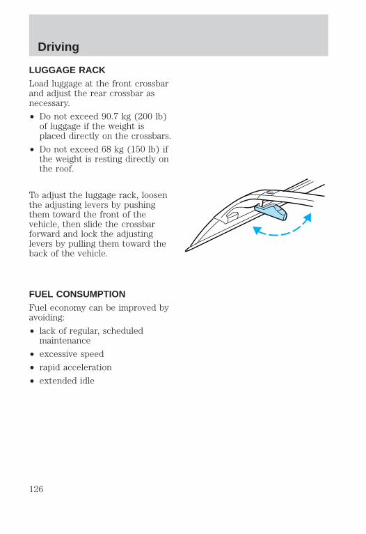
LUGGAGE RACKLoad luggage at the front crossbarand adjust the rear crossbar asnecessary.
• Do not exceed 90.7 kg (200 lb)of luggage if the weight isplaced directly on the crossbars.
• Do not exceed 68 kg (150 lb) ifthe weight is resting directly onthe roof.
To adjust the luggage rack, loosenthe adjusting levers by pushingthem toward the front of thevehicle, then slide the crossbarforward and lock the adjustinglevers by pulling them toward theback of the vehicle.
FUEL CONSUMPTIONFuel economy can be improved byavoiding:
• lack of regular, scheduledmaintenance
• excessive speed
• rapid acceleration
• extended idle
Driving
126
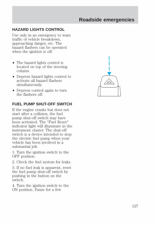
HAZARD LIGHTS CONTROLUse only in an emergency to warntraffic of vehicle breakdown,approaching danger, etc. Thehazard flashers can be operatedwhen the ignition is off.
• The hazard lights control islocated on top of the steeringcolumn.
• Depress hazard lights control toactivate all hazard flasherssimultaneously.
• Depress control again to turnthe flashers off.
FUEL PUMP SHUT-OFF SWITCHIf the engine cranks but does notstart after a collision, the fuelpump shut-off switch may havebeen activated. The “Fuel Reset”indicator light will illuminate in theinstrument cluster. The shut-offswitch is a device intended to stopthe electric fuel pump when yourvehicle has been involved in asubstantial jolt.
1. Turn the ignition switch to theOFF position.
2. Check the fuel system for leaks.
3. If no fuel leak is apparent, resetthe fuel pump shut-off switch bypushing in the button on theswitch.
4. Turn the ignition switch to theON position. Pause for a few
Roadside emergencies
127

seconds and return the key to theOFF position.
5. Make a further check for leaksin the fuel system.
The fuel pump shut-off switch islocated in the passenger’s footwell, behind the kick panel.
FUSES AND RELAYS
Fuses
If electrical components in thevehicle are not working, a fusemay have blown. Blown fuses areidentified by a broken wire withinthe fuse. Check the appropriatefuses before replacing anyelectrical components.
15 15
Roadside emergencies
128

Always replace a fuse withone that has the specified
amperage rating. Using a fusewith a higher amperage ratingcan cause severe wire damageand could start a fire.
Standard fuse amperage ratingand color
Fuse rating Color
5 amp Tan7.5 amp Brown10 amp Red15 amp Light blue20 amp Yellow20 amp fuse link Light blue25 amp Natural30 amp Light green30 amp fuse link Pink40 amp fuse link Green50 amp fuse link Red60 amp fuse link Yellow80 amp fuse link Black100 amp fuse link Dark blue
Passenger compartment fusepanelThe fuse panel is located belowand to the left of the steeringwheel by the brake pedal. Pull thepanel cover outward to access thefuses.
To remove a fuse use the fusepuller tool provided on the fusepanel cover.
Roadside emergencies
129

The fuses are coded as follows.
Fuse/Relay
Location
Fuse Amp
RatingDescription
1 15A Flasher Relay2 5A Instrument Cluster, Overhead Trip
Computer (OTC) Module3 25A Cigar Lighter4 5A Park Lamp Relay, Headlamp
Relay, Autolamp Module, RemoteAnti-Theft Personality (RAP)Module, Power Mirror Switch
1222
213
23
617
27
718
28
819
29
930
20
3121
1110
314
24
415
25
516
26
Roadside emergencies
130

Fuse/Relay
Location
Fuse Amp
RatingDescription
5 15A Digital Transmission Range (DTR)Sensor, Daytime Running Lamps(DRL) Module, Speed ControlServo/Amplifier Assembly,Heater-A/C Control Assembly,Blend Door Actuator, ElectronicVariable Orifice (EVO) Module
6 5A Shift Lock Actuator, GenericElectronic Module (GEM), 4Wheel Air Suspension (4WAS)Module, Compass Sensor, SteeringWheel Rotation Sensor, HeatedGrid Relay, Overhead TripComputer (OTC) Module
7 5A Auxiliary A/C Relay, ConsoleBlower Motor
8 5A Radio, Main Light Switch, RemoteAnti-Theft Personality (RAP)Module
9 — Not Used10 — Not Used11 30A Washer Pump Relay, Wiper
Run/Park Relay, Wiper Hi/LoRelay, Windshield Wiper Motor,Rear Wiper Pump Relay
12 5A Data Link Connector (DLC)13 15A Brake On/Off (BOO) Switch,
Brake Pressure Switch14 15A Battery Saver Relay, Interior
Lamp Relay15 5A Generic Electronic Module
(GEM), Passive Anti-Theft System(PATS) Module
Roadside emergencies
131

Fuse/Relay
Location
Fuse Amp
RatingDescription
16 20A Instrument Cluster (W/O DRL),Daytime Running Lamps (DRL)Module, Hi-Beam Headlamps(Power supplied throughMulti-Function Switch)
17 10A Heated Backlight Switch, LeftPower/Heated Signal Mirror, RightPower/Heated Signal Mirror
18 5A Main Light Switch, GenericElectronic Module (GEM),Instrument Illumination (Powersupplied through Main LightSwitch)
19 10A Instrument Cluster, Air BagDiagnostic Monitor
20 5A 4 Wheel Air Suspension (4WAS),Generic Electronic Module (GEM)
21 15A Digital Transmission Range (DTR)Sensor, Junction Box Fuse/RelayPanel (Fuse 20)
22 10A Air Bag Diagnostic Monitor23 10A Trailer Tow Battery Charge Relay,
4X4 Center Axle Disconnectsolenoid, 4X2 Center AxleDisconnect Solenoid, FunctionSelector Switch, Rear IntegratedControl Panel, RecirculationVacuum Solenoid, Auxiliary A/CMode Acturator, Auxiliary A/CControl Module
24 10A Function Selector Switch25 5A 4 Wheel Anti-Lock Brake System
(4WABS) Module, 4WABS Relay
Roadside emergencies
132

Fuse/Relay
Location
Fuse Amp
RatingDescription
26 10A Daytime Running Lamps (DRL)Module, Right Headlamp (Powersupplied through Multi-FunctionSwitch)
27 5A Main Light Switch, Fog LampRelay
28 10A Left Headlamp29 5A Autolamp Module, Instrument
Cluster, Transmission ControlSwitch (TCS)
30 30A Radio Noise Capacitor, IgnitionCoil, PCM Power Diode, Coil OnPlugs
31 — Not Used
Power distribution boxThe power distribution box islocated in the enginecompartment. The powerdistribution box containshigh-current fuses that protectyour vehicle’s main electricalsystems from overloads.
Always disconnect thebattery before servicing
high current fuses.
Always replace the coverto the Power Distribution
Box before reconnecting thebattery or refilling fluidreservoirs.
Roadside emergencies
133

The high-current fuses are codedas follows.
Fuse/Relay
Location
Fuse Amp
RatingDescription
1 20A* Trailer Tow Running Lamp Relay,Trailer Tow Backup Lamp Relay
2 10A* Air Bag Diagnostic Monitor3 30A* All Unlock Relay, All Lock Relay,
Driver’s Unlock Relay4 15A* Air Suspension Service Switch5 20A* Horn Relay6 30A* Radio, Premium Sound Amplifier,
CD Changer, Rear IntegratedControl Panel, Sub-Woofer Power(Fuse 3 & Fuse 5)
1929
1828
EE
CP
OW
ER
RE
LA
Y
FU
EL
PU
MP
RE
LA
Y
FR
ON
TW
AS
HE
RP
UM
P
HO
RN
RE
LA
Y17
27
1626
1525
1424
13
1112
910
78
56
34
12
23 22 21 20
W/S
/WR
UN
/PA
RK
W/S
/WH
I/LO
Roadside emergencies
134
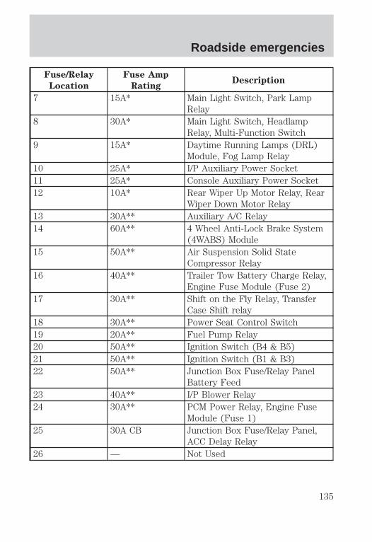
Fuse/Relay
Location
Fuse Amp
RatingDescription
7 15A* Main Light Switch, Park LampRelay
8 30A* Main Light Switch, HeadlampRelay, Multi-Function Switch
9 15A* Daytime Running Lamps (DRL)Module, Fog Lamp Relay
10 25A* I/P Auxiliary Power Socket11 25A* Console Auxiliary Power Socket12 10A* Rear Wiper Up Motor Relay, Rear
Wiper Down Motor Relay13 30A** Auxiliary A/C Relay14 60A** 4 Wheel Anti-Lock Brake System
(4WABS) Module15 50A** Air Suspension Solid State
Compressor Relay16 40A** Trailer Tow Battery Charge Relay,
Engine Fuse Module (Fuse 2)17 30A** Shift on the Fly Relay, Transfer
Case Shift relay18 30A** Power Seat Control Switch19 20A** Fuel Pump Relay20 50A** Ignition Switch (B4 & B5)21 50A** Ignition Switch (B1 & B3)22 50A** Junction Box Fuse/Relay Panel
Battery Feed23 40A** I/P Blower Relay24 30A** PCM Power Relay, Engine Fuse
Module (Fuse 1)25 30A CB Junction Box Fuse/Relay Panel,
ACC Delay Relay26 — Not Used
Roadside emergencies
135

Fuse/Relay
Location
Fuse Amp
RatingDescription
27 40A** Junction Box Fuse/Relay Panel,Heated Grid Relay
28 30A** Trailer Electronic BrakeController
29 30A** Flip Window Relay, HybridCooling Fan Relay
* Mini Fuses ** Maxi Fuses
RelaysRelays are located in the powerdistribution box and should bereplaced by qualified technicians.
Primary battery fuses(megafuses)
Roadside emergencies
136

The primary battery fuses arelocated in the engine compartmentnear the battery.
Ford recommends that themegafuses are serviced by aqualified service technician.
Location Amperage Description
1 175 Power Network Box Megafuse2 175 Alternator Megafuse3 20 Alternator Field Minifuse
Engine mini fuse box
20A
12
3
Roadside emergencies
137

The engine mini fuses are locatedon the drivers side of the enginecompartment.
Slot
Number
Fuse
Amperage
Rating
Circuits Protected
1 5 amp Powertrain Control Module (PCM)2 20 amp Trailer Tow Stop/Turn Lamps3 10 amp Audio Rear Integrated Control Panel
(RICP), Compact Disc Changer, Radio4 10 amp Running Board Lamps5 20 amp Amplifier, Subwoofer Amplifier6 — Not Used
CHANGING THE TIRESIf you get a flat tire while driving,do not apply the brake heavily.Instead, gradually decrease yourspeed. Hold the steering wheelfirmly and slowly move to a safeplace on the side of the road.
6
5
4
3
2
1
Roadside emergencies
138

Spare tire informationYour vehicle is equipped with aspare tire that may be used as aspare or a regular tire. The spareis identical to the other tires onyour vehicle, although the wheelcover may not match.
Location of the spare tire andtoolsThe spare tire and tools for yourvehicle are stowed in the followinglocations:
Item Location
Spare tire Under the vehicle, just forward ofthe rear bumper
Jack, wheel nut wrench,instructions, work gloves
Behind the access panel locatedon the right rear quarter panelinterior trim
Jack handle On top of the radiator support atthe front of the enginecompartment
Removing the jack handle1. Open the hood.
2. Un-snap the end of the handlethat is retained by the clip on thetop of the windshield washerbottle.
3. Un-snap the shaft of the handlefrom the two retaining clipsattached to the top of the radiatorshroud.
Roadside emergencies
139

Removing the jack and tools1. Locate the access panel on theinterior trim. Lift and rotate thetwo panel retaining clips andremove the panel.
2. Un-snap the wheel lug nutwrench, instructions and workgloves from their retaining bracket.
3. Remove the jack by turning thethumbwheel counterclockwise torelieve tension against the stowagebracket.
Removing the spare tire1. Open the liftgate.
2. Insert the straight end of thejack handle into the rear accesshole located just above the rearbumper.
Forward motion will stop andresistance to turning will be feltwhen properly engaged.
3. Turn the handlecounterclockwise until tire islowered to the ground and thecable is slightly slack.
4. Remove the retainer from thespare tire.
Stowing the spare1. Lay the tire on the ground withthe outboard side facing up.
Roadside emergencies
140

2. Install the retainer through thewheel center and slide the wheelunder the vehicle.
3. Turn the spare handle clockwiseuntil the tire is raised to itsoriginal position underneath thevehicle. The spare handle ratchetswhen the tire is raised to thestowed position. It will not allowyou to overtighten.
Tire change procedure
On vehicles equipped withAir Suspension, turn OFF
the Air Suspension switch priorto jacking, hoisting or towingyour vehicle.
Refer to the instruction sheet(located behind the interior trimaccess panel with the jack) fordetailed tire change instructions.
1. Park on a level surface, activatehazard flashers and set the parkingbrake.
2. Place gearshift lever in P (Park).BRAKE
HOOD
Roadside emergencies
141

3. Block the diagonally oppositewheel.
4. Obtain the spare tire and jackfrom their storage locations.
5. Use the tip of the lug wrench toremove any wheel trim.
6. Loosen each wheel lug nutsone-half turn counterclockwise butdo not remove them until thewheel is raised off the ground.
7. Turn OFF the air suspensionswitch (if equipped).
8. Position the jack according tothe following guides and turn thejack handle clockwise until thewheel is completely off the ground.
When one of the rear wheels is offthe ground, the transmission alonewill not prevent the vehicle frommoving or slipping off the jack,even if the transmission is in P(Park). To prevent the vehiclefrom moving when you change thetire, be sure that the parking brakeis set and the diagonally oppositewheel is blocked. If the vehicleslips off the jack, someone couldbe seriously injured.
OFF
Roadside emergencies
142

• Front (4x2)
• Front (4x4)
• Rear
Roadside emergencies
143

• Never use the front or reardifferential as a jackingpoint.
9. Remove the lug nuts with thelug wrench.
10. Replace the flat tire with thespare tire, making sure the valvestem is facing outward. Reinstallthe lug nuts until the wheel is snugagainst the hub. Do not fullytighten the lug nuts until thewheel has been lowered.
11. Lower the wheel by turning thejack handle counterclockwise.
12. Remove the jack and fullytighten the lug nuts in the ordershown.
13. Put flat tire, jack and lugwrench away. Make sure the jack isfastened so it does not rattle whenyou drive.
14. Unblock the wheels.
15. Turn on the air suspensionswitch (if equipped).
1
43
5 2
Roadside emergencies
144

JUMP STARTING YOURVEHICLE
The gases around thebattery can explode if
exposed to flames, sparks, or litcigarettes. An explosion couldresult in injury or vehicledamage.
Do not push start yourvehicle. You could damage
the catalytic converter.
Batteries contain sulfuricacid which burns skin,
eyes, and clothing.
Preparing your vehicleAlso see the label on the battery.
1. Use only a 12–volt supply tostart your vehicle. If you connectyour battery to a 24–volt powersupply you can damage yourstarter, ignition system and otherelectrical components.
2. Do not disconnect the battery ofthe disabled vehicle as this coulddamage the vehicle’s electricalsystem.
3. Park the booster vehicle close tothe hood of the disabled vehiclemaking sure they do not touch.Set the parking brake on bothvehicles and stay clear of theengine cooling fan and othermoving parts.
Roadside emergencies
145

4. Check all battery terminals andremove any excessive corrosionbefore you attach the batterycables.
5. Turn the heater fan on in bothvehicles to protect any electricalsurges. Turn all other accessoriesoff.
Connecting the jumper cables
1. Position the vehicles so thatthey do not touch one another.
2. Switch off the engine. Switch offany unnecessary electricalequipment.
3. Connect the positive (+)terminal of the discharged battery(1) to the positive (+) terminal ofthe booster battery (2).
4. Connect one end of the secondlead to the negative (-) terminal ofthe booster battery (3) and theother end to a metal part of theengine to be started (4), not to thenegative (-) terminal of thedischarged battery.
5. Make sure that the jump leadsare clear of moving parts of theengine.
Do not connect the end ofthe second cable to the
negative (-) terminal of thebattery to be jumped. A sparkmay cause an explosion of thegases that surround the battery.
+
–
+
–
1 4
3
2
Roadside emergencies
146

Jump starting1. Start the booster vehicle andrun the engine at moderatelyincreased speed.
2. Start the engine of the vehiclewith the discharged battery.
3. Once the engine has beenstarted, run both vehicles for afurther three minutes beforedisconnecting the leads.
Removing the jumper cables
1. Remove the jumper cables inreverse order. Take the cable offthe metallic surface (1) first,followed by the cable on thenegative (-) booster batteryterminal (2).
2. Remove the cable from thepositive (+) terminal of the boosterbattery (3) and then thedischarged battery (4).
3. After the disabled vehicle hasbeen started, allow it to idle for awhile so the engine can “relearn”its idle conditions.
+
–
+–
4 1
2
3
Roadside emergencies
147
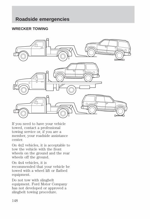
WRECKER TOWING
If you need to have your vehicletowed, contact a professionaltowing service or, if you are amember, your roadside assistancecenter.
On 4x2 vehicles, it is acceptable totow the vehicle with the frontwheels on the ground and the rearwheels off the ground.
On 4x4 vehicles, it isrecommended that your vehicle betowed with a wheel lift or flatbedequipment.
Do not tow with slingbeltequipment. Ford Motor Companyhas not developed or approved aslingbelt towing procedure.
Roadside emergencies
148
When calling for a tow truck, tellthe operator what kind of vehicleyou have. A towing manual isavailable from Ford MotorCompany for all authorized towtruck operators. Have your towtruck driver refer to this manualfor proper hook-up and towingprocedures for your vehicle.
Roadside emergencies
149

SERVICE RECOMMENDATIONSTo help you service your vehicle:
• We highlight do-it-yourself itemsin the engine compartment foreasy location.
• We provide a “Service Guide”which makes tracking routineservice easy.
If your vehicle requiresprofessional service, yourdealership can provide necessaryparts and service. Check your“Warranty Guide” to find out whichparts and services are covered.
Use only recommended fuels,lubricants, fluids and service partsconforming to specifications.Motorcraft parts are designed andbuilt to provide the bestperformance in your vehicle.
PRECAUTIONS WHENSERVICING YOUR VEHICLEBe especially careful wheninspecting or servicing yourvehicle.
• Do not work on a hot engine.
• When the engine is running,make sure that loose clothing,jewelry or long hair does not getcaught up in moving parts.
• Do not work on a vehicle withthe engine running in anenclosed space, unless you aresure you have enoughventilation.
Maintenance and care
150

• Keep all lit cigarettes, openflames and other lit materialaway from the battery and allfuel related parts.
If you disconnect the battery, theengine must “relearn” its idleconditions before your vehicle willdrive properly, as explained inBattery in this chapter.
Working with the engine off1. Set the parking brake andensure the gearshift is securelylatched in P (Park).
2. Turn off the engine and removethe key.
3. Block the wheels to prevent thevehicle from moving unexpectedly.
Working with the engine on.1. Set the parking brake andensure the gearshift is securelylatched in P (Park).
2. Block the wheels to prevent thevehicle from moving unexpectedly.
Do not start your enginewith the air cleaner
removed and do not remove itwhile the engine is running.
Maintenance and care
151

OPENING THE HOOD
1. Inside the vehicle, pull the hoodrelease handle located under thebottom of the instrument panel.
2. Go to the front of the vehicleand release the auxiliary latch thatis located under the front center ofthe hood. Lift the hood until thelift cylinders hold it open.
IDENTIFYING COMPONENTS INTHE ENGINE COMPARTMENT
4.6L/5.4L engines
1. Battery
BRAKE
HOOD
10 9
1 2 3 4 5 6
8
7
Maintenance and care
152

2. Automatic transmission fluiddipstick
3. Engine oil filler
4. Engine oil dipstick
5. Power steering fluid reservoir
6. Brake fluid reservoir
7. Power distribution box
8. Air filter assembly
9. Engine coolant recoveryreservoir
10. Windshield washer fluidreservoir
ENGINE OIL
Checking the engine oilCheck the engine oil each time youfuel your vehicle.
1. Make sure the vehicle is on levelground.
2. Turn the engine off and wait afew minutes for the oil to draininto the oil pan.
3. Set the parking brake andensure the gearshift is securelylatched in P (Park).
4. Open the hood. Protect yourselffrom engine heat.
Maintenance and care
153

5. Locate and carefully remove theengine oil level indicator(dipstick).
6. Wipe the indicator clean. Insertthe indicator fully, then remove itagain.
• If the oil level is between theMIN and MAX marks, the oillevel is acceptable. DO NOTADD OIL.
• If the oil level is below the MINmark, add enough oil to raisethe level within the MIN-MAXrange.
MIN MAX
Maintenance and care
154
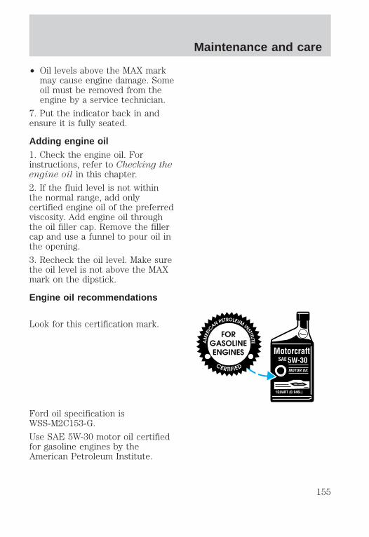
• Oil levels above the MAX markmay cause engine damage. Someoil must be removed from theengine by a service technician.
7. Put the indicator back in andensure it is fully seated.
Adding engine oil1. Check the engine oil. Forinstructions, refer to Checking theengine oil in this chapter.
2. If the fluid level is not withinthe normal range, add onlycertified engine oil of the preferredviscosity. Add engine oil throughthe oil filler cap. Remove the fillercap and use a funnel to pour oil inthe opening.
3. Recheck the oil level. Make surethe oil level is not above the MAXmark on the dipstick.
Engine oil recommendations
Look for this certification mark.
Ford oil specification isWSS-M2C153-G.
Use SAE 5W-30 motor oil certifiedfor gasoline engines by theAmerican Petroleum Institute.
Maintenance and care
155
Do not use supplemental engine oiladditives, oil treatments or enginetreatments. They are unnecessaryand could, under certainconditions, lead to engine damagewhich is not covered by yourwarranty.
Changing the engine oil andfilterChange your engine oil and filteraccording to the following mileageand time requirements, whicheveroccurs first:
• Normal Schedule – 8,000 km(5,000 miles) or six months.
• Severe Duty Schedule - 5,000km (3,000 miles) or threemonths. Severe duty operationwould include extensive idling,trailer towing, driving in severedust and police, taxi or deliveryservice.
Ford production and aftermarket(Motorcraft) oil filters are designedfor added engine protection andlong life. If a replacement oil filteris used that does not meet Fordmaterial and design specifications,startup engine noises or knockmay be experienced.
It is recommended you use theappropriate Motorcraft oil filter (oranother brand meeting Fordspecifications) for your engineapplication.
Maintenance and care
156

BRAKE FLUID
Checking and adding brakefluid
Brake fluid should be checked andrefilled as needed at least onceeach year:
1. Clean the reservoir cap beforeremoval to prevent dirt or waterfrom entering the reservoir.
2. Visually inspect the fluid level.
3. If necessary, add brake fluiduntil the level reaches MAX. Donot fill above this line.
4. Use only a DOT 3 brake fluidcertified to meet Fordspecifications. Refer to Lubricantspecifications in the Capacitiesand specifications chapter.
Brake fluid is toxic.
If you use a brake fluidthat is not DOT 3, you will
cause permanent damage to yourbrakes.
Do not let the reservoir forthe master cylinder run
dry. This may cause the brakesto fail.
MAX
MIN
Maintenance and care
157

WINDSHIELD WASHER FLUID
Checking and adding washerfluid
Check the washer fluid wheneveryou stop for fuel. The reservoir ishighlighted with a symbol.
If the level is low, add enough fluidto fill the reservoir. In very coldweather, do not fill the reservoir allthe way.
Do not put engine coolantin the container for the
windshield washer fluid.
Checking and adding washerfluid for the liftgateWasher fluid for the liftgate issupplied by the same reservoir asthe windshield.
ENGINE COOLANT
Check the level of the coolant inthe reservoir at least once amonth. Be sure to read andunderstand Precautions whenservicing your vehicle in thischapter.
If the engine coolant has not beenchecked for a long period of time,the engine coolant reservoir may
Maintenance and care
158

eventually empty. If this occurs,add engine coolant to the coolantreservoir. For more information onengine coolant maintenance, referto Adding engine coolant in thischapter.
Automotive fluids are notinterchangeable; do not use enginecoolant, antifreeze or windshieldwasher fluid outside of its specifiedfunction and vehicle location.
Adding engine coolant
Do not put engine coolantin the container for the
windshield washer fluid.
If sprayed on the windshield,engine coolant could make itdifficult to see through thewindshield.
When the engine is cool, add a50/50 mixture of engine coolantand water to the engine coolantrecovery reservoir-DO NOT ADDDIRECTLY TO THE RADIATOR.Add straight water only in anemergency, but you should replaceit with a 50/50 mixture of coolantand distilled water as soon aspossible.
Check the coolant level in thecoolant recovery reservoir the nextfew times you drive the vehicle. Ifnecessary, add enough of a 50/50mixture of coolant and water tobring the liquid level to the fill lineon the reservoir.
Maintenance and care
159

Never remove the coolantrecovery cap while the
engine is running or hot.
If you must remove the coolantrecovery cap, follow these steps toavoid personal injury:
1. Before you remove the cap, turnthe engine off and let it cool.
2. When the engine is cool, wrap athick cloth around the cap. Slowlyturn cap counterclockwise to thefirst stop.
3. Step back while the pressurereleases.
4. When you are sure that all thepressure has been released, usethe cloth to press the cap down,turn it counterclockwise andremove it.
Use Ford Premium Cooling SystemFluid E2FZ-19549–AA (in Canada,Motorcraft CXC-8–B) or anequivalent premium engine coolantthat meets Ford specificationESE-M97B44–A. Ford PremiumEngine Coolant is an optimizedformula that will protect all metalsand rubber elastomers used inFord cooling systems for four yearsor 80,000 km (50,000 miles).
Do not use alcohol or methanolantifreeze or any engine coolantsmixed with alcohol or methanolantifreeze. Do not usesupplemental coolant additives inyour vehicle. These additives mayharm your engine cooling system.The use of an improper coolant
Maintenance and care
160

may void your warranty of yourvehicle’s engine cooling system.
Recycled engine coolantFord Motor Company recommendsthat Ford and Lincoln-Mercurydealers use recycled enginecoolant produced byFord-approved processes. Not allcoolant recycling processesproduce coolant which meets Fordspecification ESE-M97B44–A, anduse of such coolant may harmengine and cooling systemcomponents.
Always dispose of usedautomotive fluids in a responsiblemanner. Follow your community’sregulations and standards forrecycling and disposing ofautomotive fluids.
Coolant refill capacityTo find out how much fluid yourvehicle’s cooling system can hold,refer to Refill capacities in theCapacities and specificationschapter.
Have your dealer check the enginecooling system for leaks if youhave to add more than a liter(quart) of engine coolant permonth.
Severe winter climateIf you drive in extremely coldclimates (less than –36°C [–34°F]),it may be necessary to increase thecoolant concentration above 50%.Refer to the chart on the coolant
Maintenance and care
161

container to ensure the coolantconcentration in your vehicle issuch that the coolant will notfreeze at the temperature level inwhich you drive during wintermonths. Never increase the enginecoolant concentration above 60%.Leave a 50/50 mixture of enginecoolant and water in your vehicleyear-round in non-extremeclimates.
What you should know aboutfail-safe coolingIf the engine coolant supply isdepleted, this feature allows thevehicle to be driven temporarilybefore incremental componentdamage is incurred. The “fail safe”distance depends on ambienttemperatures, vehicle load andterrain.
How fail-safe cooling works
If the engine overheats, the enginewill automatically switch fromeight to alternating four cylinderoperation. Each disabled cylinderacts as an air pump and cools theengine.
When this occurs, the enginecoolant temperature gauge willmove into the red area and the
light illuminates.
The check engine light willilluminate, indicating that vehicleservice is required.
The vehicle will still operate, butwill have limited engine power and
TEMPH
C
Maintenance and care
162

no air conditioning capability.
Continued operation will increaseengine temperature and cause theengine to completely shut down.The vehicle will coast to a stop.
As the engine temperature cools,the engine may be re-started. Takeyour vehicle to a service facility assoon as possible to minimizeengine damage.
When fail-safe mode isactivated• Pull off the road as soon as
possible.
• Immediately turn the engine offto prevent severe enginedamage.
• Wait for the engine to cool.
• Check the coolant level.
CHECKING AND ADDINGPOWER STEERING FLUID
Check the power steering fluid atleast twice a year. If adding fluid isnecessary, use only MERCONtATF power steering fluid.
1. Start the engine and let it rununtil it reaches normal operatingtemperature (the engine coolanttemperature gauge will be near thecenter of the NORMAL band).
Maintenance and care
163
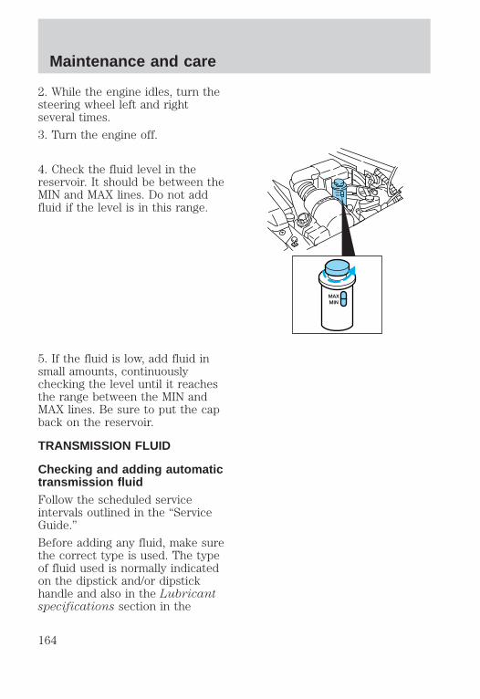
2. While the engine idles, turn thesteering wheel left and rightseveral times.
3. Turn the engine off.
4. Check the fluid level in thereservoir. It should be between theMIN and MAX lines. Do not addfluid if the level is in this range.
5. If the fluid is low, add fluid insmall amounts, continuouslychecking the level until it reachesthe range between the MIN andMAX lines. Be sure to put the capback on the reservoir.
TRANSMISSION FLUID
Checking and adding automatictransmission fluidFollow the scheduled serviceintervals outlined in the “ServiceGuide.”
Before adding any fluid, make surethe correct type is used. The typeof fluid used is normally indicatedon the dipstick and/or dipstickhandle and also in the Lubricantspecifications section in the
MAXMIN
MAXMIN
Maintenance and care
164
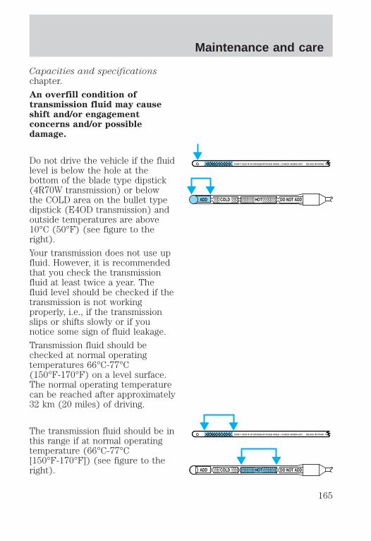
Capacities and specificationschapter.
An overfill condition oftransmission fluid may causeshift and/or engagementconcerns and/or possibledamage.
Do not drive the vehicle if the fluidlevel is below the hole at thebottom of the blade type dipstick(4R70W transmission) or belowthe COLD area on the bullet typedipstick (E4OD transmission) andoutside temperatures are above10°C (50°F) (see figure to theright).
Your transmission does not use upfluid. However, it is recommendedthat you check the transmissionfluid at least twice a year. Thefluid level should be checked if thetransmission is not workingproperly, i.e., if the transmissionslips or shifts slowly or if younotice some sign of fluid leakage.
Transmission fluid should bechecked at normal operatingtemperatures 66°C-77°C(150°F-170°F) on a level surface.The normal operating temperaturecan be reached after approximately32 km (20 miles) of driving.
The transmission fluid should be inthis range if at normal operatingtemperature (66°C-77°C[150°F-170°F]) (see figure to theright).
DON'T ADD IF IN CROSSHATCHED AREA • CHECK WHEN HOT IDLING IN PARK
ADD COLD HOT DO NOT ADD
DON'T ADD IF IN CROSSHATCHED AREA • CHECK WHEN HOT IDLING IN PARK
ADD COLD HOT DO NOT ADD
Maintenance and care
165

The transmission fluid should be inthis range if at room temperature(10°C-35°C [50°F-95°F]) (seefigure to the right).
If your vehicle has been operatedfor an extended period at highspeeds, in city traffic during hotweather or pulling a trailer, thevehicle should be turned off forabout 30 minutes to allow the fluidto cool before checking.
1. Park the vehicle on a levelsurface and engage the parkingbrake.
2. With the parking brake engagedand your foot on the brake pedal,start the engine and move thegearshift lever through all of thegear ranges. Allow sufficient timefor each gear to engage.
3. Latch the gearshift lever in P(Park) and leave the enginerunning.
4. Remove the dipstick, wiping itclean with a clean, dry lint freerag.
5. Install the dipstick making sureit is fully seated in the filler tube.
6. Remove the dipstick and inspectthe fluid level. The fluid levelshould be in the crosshatched areaon the dipstick.
DON'T ADD IF IN CROSSHATCHED AREA • CHECK WHEN HOT IDLING IN PARK
ADD COLD HOT DO NOT ADD
P R N D 2 1
Maintenance and care
166

7. If necessary, add fluid in .25L(1/2 pint) increments through thefiller tube until the level is correct.
8. If an overfill occurs, excess fluidshould be removed by a qualifiedtechnician.
An overfill condition oftransmission fluid may causeshift and/or engagementconcerns and/or possibledamage.
If the fluid level is above the topnotch of the hot range after drivingthe vehicle for approximately 30km (20 miles), excess fluid shouldbe removed by a qualifiedtechnician.
DRIVELINE UNIVERSAL JOINTAND SLIP YOKEThe universal joints standard withyour vehicle do not requirelubrication. If the original universaljoints are replaced with universaljoints equipped with greasefittings, lubrication will benecessary.
DON'T ADD IF IN CROSSHATCHED AREA • CHECK WHEN HOT IDLING IN PARK
ADD COLD HOT DO NOT ADD
Maintenance and care
167

BATTERY
Your vehicle may be equipped witha Motorcraft maintenance-freebattery. If the original equipmentbattery needs replacing, it may bereplaced with a low-maintenancebattery. The low-maintenancebattery normally does not requireadditional water during its life ofservice. However, for severe usageor in high temperature climates,check your battery electrolytelevel, at least every 24 months or40,000 km (24,000 miles). Keepthe electrolyte in each cell up tothe “level” indicator. Do not overfillthe battery cells.
If the electrolyte level in thebattery is low, you can add plaintap water to the battery, as long asyou do not use hard water (waterwith a high alkali content). Ifpossible, however, try to only fillthe battery cells with distilledwater. If the battery needs wateroften, have the charging systemchecked.
For longer, trouble-free operation,keep the top of the battery cleanand dry. Also, make certain thebattery cables are always tightlyfastened to the battery terminals.
If you see any corrosion on thebattery or terminals, remove thecables from the terminal(s) andclean with a wire brush. You canneutralize the acid with a solutionof baking soda and water. Reinstallthe cables when you are done
Maintenance and care
168

cleaning them, and apply a smallquantity of grease to the top ofeach battery terminal to helpprevent corrosion.
If your battery has acover/shield, make sure it isreinstalled after the battery isreplaced.
Because your vehicle’s engine iselectronically controlled by acomputer, some control conditionsare maintained by power from thebattery. When the battery isdisconnected or a new battery isinstalled, the engine must relearnits idle conditions before yourvehicle will drive properly. Tobegin this process:
1. Put the gearshift in P (Park),turn off all accessories and startthe vehicle.
2. Let the engine idle for at leastone minute.
3. The relearning process willautomatically complete as youdrive the vehicle.
• If you do not allow the engine torelearn its idle, the idle qualityof your vehicle may be adverselyaffected until the idle iseventually relearned.
• If the battery has beendisconnected or a new batteryhas been installed, the clock andthe preset radio stations mustbe reset once the battery isreconnected.
Maintenance and care
169

• Always dispose of automotivebatteries in a responsiblemanner. Follow yourcommunities standards fordisposal. Call your localrecycling center to find outmore about recycling automotivebatteries.
AIR CLEANER FILTERMAINTENANCERefer to the “Service Guide” forthe appropriate intervals forchanging the air cleaner filter.
Do not start your enginewith the air cleaner
removed and do not remove itwhile the engine is running.
CHANGING THE AIR FILTER
1. Loosen the clamp that securesthe air cleaner in place.
2. Separate the two halves of theair cleaner.
3. Remove the air filter elementfrom the open end of the engineair cleaner and replace it with anew element. Be careful not tocrimp the filter edges betweenhalves. This could cause filterdamage if not properly seated.
4. Replace the two halves of theair cleaner and secure the clamp.
Maintenance and care
170

For information on replacement airfilter elements, refer to theCapacities and specificationschapter.
WINDSHIELD WIPER BLADESCheck the wiper blades at leasttwice a year or when they seemless effective. Substances such astree sap and some hot waxtreatments used by commercial carwashes reduce the effectiveness ofwiper blades.
Checking the wiper bladesIf the wiper blades do not wipeproperly, clean both the windshieldand wiper blades using undilutedwindshield wiper solution or a milddetergent. Rinse thoroughly withclean water. To avoid damaging theblades, do not use fuel, kerosene,paint thinner or other solvents.
Changing the wiper bladesWhen replacing wiper bladeassemblies, always use aMotorcraft part or equivalent. Tomake replacing the wipers easy,turn the ignition to ACC, then turnthe wipers on. When the wipersreach the vertical position, turnthe ignition to LOCK.
To replace the wiper blades:
Maintenance and care
171

1. Pull the wiper arm away fromthe windshield and lock into theservice position.
2. Turn the blade at an angle fromthe wiper arm. Push the lock pinwith a screwdriver to release theblade and pull the wiper bladedown toward the windshield toremove it from the arm.
3. Attach the new wiper to thewiper arm and press it into placeuntil a click is heard.
INFORMATION ABOUT TIREQUALITY GRADES
New vehicles are fitted with tiresthat have their Tire Quality Grade(described below) molded into thetire’s sidewall. These Tire QualityGrades are determined bystandards that the United StatesDepartment of Transportation hasset.
Tire Quality Grades apply to newpneumatic tires for use onpassenger cars. They do not applyto deep tread, winter-type snowtires, space-saver or temporary usespare tires, tires with nominal rimdiameters of 10 to 12 inches orlimited production tires as definedin Title 49 Code of FederalRegulations Part 575.104(c)(2).
Maintenance and care
172

U.S. Department ofTransportation-Tire qualitygrades: The U.S. Department ofTransportation requires Ford togive you the following informationabout tire grades exactly as thegovernment has written it.
TreadwearThe treadwear grade is acomparative rating based on thewear rate of the tire when testedunder controlled conditions on aspecified government test course.For example, a tire grade 150would wear one and one-half(1 1/2) times as well on thegovernment course as a tire grade100. The relative performance oftires depends upon the actualconditions of their use, however,and may depart significantly fromthe norm due to variations indriving habits, service practices,and differences in roadcharacteristics and climate.
Traction A B CThe traction grades, from highestto lowest are A, B, and C, and theyrepresent the tire’s ability to stopon wet pavement as measuredunder test surfaces of asphalt andconcrete. A tire marked C mayhave poor traction performance.
The traction gradeassigned to this tire is
based on braking (straightahead) traction tests and doesnot include cornering (turning)traction.
Maintenance and care
173

Temperature A B CThe temperature grades are A (thehighest), B, and C, representingthe tire’s resistance to thegeneration of heat and its ability todissipate heat when tested undercontrolled conditions on aspecified indoor laboratory testwheel. Sustained high temperaturecan cause the material of the tireto degenerate and reduce tire life,and excessive temperature canlead to sudden tire failure. Thegrade C corresponds to a level ofperformance which all passengercar tires must meet under theFederal Motor Vehicle SafetyStandard No. 109. Grades B and Arepresent higher levels ofperformance on the laboratory testwheel than the minimum requiredby law.
The temperature grade forthis tire is established for a
tire that is properly inflated andnot overloaded. Excessive speed,underinflation, or excessiveloading, either separately or incombination, can cause heatbuildup and possible tire failure.
SERVICING YOUR TIRES
Checking the tire pressure• Use an accurate tire pressure
gauge.
• Check the tire pressure whentires are cold, after the vehicle
Maintenance and care
174

has been parked for at least onehour or has been driven lessthan 5 km (3 miles).
• Adjust tire pressure torecommended specificationsfound on the Safety ComplianceCertification Label.
Improperly inflated tirescan affect vehicle handling
and can fail suddenly, possiblyresulting in loss of vehiclecontrol.
Tire rotationBecause your vehicle’s tiresperform different jobs, they oftenwear differently. To make sureyour tires wear evenly and lastlonger, rotate them as indicated inthe “Service Guide.” If you noticethat the tires wear unevenly, havethem checked.
• Four tire rotation
Maintenance and care
175

Replacing the tires
Replace the tires when the wearband is visible through the tiretreads.
Failure to follow theseprecautions may adversely
affect the handling of the vehicleand make it easier to lose controland roll over.
Tires that are larger or smallerthan your vehicle’s original tiresmay also affect the accuracy ofyour speedometer.
SNOW TIRES AND CHAINS
Snow tires must be thesame size and grade as the
tires you currently have on yourvehicle.
The tires on your vehicle have allweather treads to provide tractionin rain and snow. However, in someclimates, you may need to usesnow tires and chains.
Follow these guidelines when usingsnow tires and chains:
• Use only cable type chainsoffered by Ford as an accessory
Maintenance and care
176

or equivalent. SAE class “S” orother conventional link typechains may contact and causedamage to the vehicle’s wheelhouse and/or body.
• Install chains securely, verifyingthat the chains do not touch anywiring, brake lines or fuel lines.
• Drive cautiously. If you hear thechains rub or bang against yourvehicle, stop and re-tighten thechains. If this does not work,remove the chains to preventdamage to your vehicle.
• If possible, avoid fully loadingyour vehicle.
• Remove the tire chains whenthey are no longer needed. Donot use tire chains on dry roads.
• The suspension insulation andbumpers will help preventvehicle damage. Do not removethese components from yourvehicle when using snow tiresand chains.
• Do not exceed 48 km/h (30mph) with tire chains on yourvehicle.
WHAT YOU SHOULD KNOWABOUT AUTOMOTIVE FUELS
Important safety precautions
Do not overfill the fueltank. The pressure in an
overfilled tank may causeleakage and lead to fuel sprayand fire.
Maintenance and care
177

If you do not use theproper fuel cap, the
pressure in the fuel tank candamage the fuel system or causeit to work improperly in acollision.
The fuel system may beunder pressure. If the fuel
cap is venting vapor or if youhear a hissing sound, wait until itstops before completelyremoving the cap.
Automotive fuels cancause serious injury or
death if misused or mishandled.
Observe the following guidelineswhen handling automotive fuel:
• Extinguish all smoking materialsand any open flames beforefueling your vehicle.
• Always turn off the vehiclebefore fueling.
• Automotive fuels can be harmfulor fatal if swallowed. If fuel isswallowed, call a physicianimmediately, even if nosymptoms are immediatelyapparent. The toxic effects offuel may not be visible forhours.
• Fuels can also be harmful ifabsorbed through the skin. Iffuel is splashed on the skin,
Maintenance and care
178

promptly remove contaminatedclothing and wash skinthoroughly with soap and water.
• If fuel is splashed in the eyes,remove contact lenses, flushwith water for 15 minutes andseek medical attention.
• Be particularly careful if you aretaking “Antabuse” or otherforms of disulfiram for thetreatment of alcoholism.Breathing gasoline vapors orskin contact could cause anadverse reaction. Consult aphysician immediately.
Choosing the right fuelUse only UNLEADED FUEL. Theuse of leaded fuel is prohibited bylaw and could damage yourvehicle.
Your vehicle was not designed touse fuel or fuel additives withmetallic compounds, includingmanganese-based compoundscontaining MMT.
Vehicles certified to Californiaemission standards (indicated onthe underhood Vehicle EmissionsControl Information label) aredesigned to operate on Californiareformulated gasolines. IfCalifornia reformulated gasoline isnot available when you refuel, yourvehicle can be operated onnon-California fuels. However, eventhough your engine will performadequately on other gasolines, theperformance of the emission
Maintenance and care
179

control devices and systems maybe adversely affected.
Repair of damage caused by usinga fuel that your vehicle was notdesigned for may not be coveredby your warranty.
Octane recommendations
Your vehicle is designed to useregular unleaded with an (R+M)/2octane rating of 87. We do notrecommend gasolines labeled as“regular” in high altitude areas thatare sold with octane ratings of 86or even less.
Do not be concerned if yourvehicle sometimes knocks lightly.However, if it knocks heavily undermost driving conditions on fuelwith the recommended octane, seeyour dealer or a qualified servicetechnician to prevent any enginedamage.
Fuel qualityIf you are experiencing starting,rough idle or hesitation problemstry a different brand of fuel. If thecondition persists, see your dealeror a qualified service technician.
The American AutomobileManufacturers Association (AAMA)issued a gasoline specification toprovide information on high qualityfuels that optimize theperformance of your vehicle. We
87
Maintenance and care
180

recommend the use of gasolinesthat meet the AAMA specificationif they are available.
It should not be necessary to addany aftermarket products to yourfuel tank if you continue to use ahigh-quality fuel.
Cleaner airFord approves the use of gasolinesto improve air quality, includingreformulated gasolines that containoxygenates up to 10% ethanol or15% MTBE.
Do not use gasolines containingmethanol, which can damagecritical fuel system components.Damage resulting from the use ofmethanol may not be covered byyour warranty.
Filling the fuel tank
1. Turn the engine off. Afteropening the fuel door, remove thecap carefully and slowly by turningit counterclockwise 1⁄4 turn until itstops. Pull to remove the cap. Atether attaches the cap to the fuelfiller pipe.
2. Make sure that you pumpunleaded fuel and put the fuelnozzle inside the fuel filler pipe.
• To optimize fill, it may benecessary to reposition thenozzle in the filler pipe.
SNAP
ON
SNA
P
REM0VE
THENPULLTO
Maintenance and care
181

• To help reduce early nozzle shutoff and fuel spillage, park yourvehicle so the fuel filler door islevel.
• Avoid excessively fast fueldispensing rates (over 38 L[10 gallons] per minute).
• If you spill fuel on the body ofyour vehicle, clean it offimmediately. The fuel may dullor soften the paint if it is notwashed off promptly.
• To replace the fuel cap, alignthe tabs on the cap with thenotches on the fuel filler pipe.Turn it clockwise until it stops.
• Push the fuel door closed.
If the check engine warning lightilluminates and remains illuminatedwhile the engine is started, thefuel cap may not be properlyseated. Turn off the engine,remove the fuel cap and replace it,being sure to align the capproperly.
If the cap is lost, replace it with anauthorized Motorcraft or equivalentpart.
Calculating fuel economyTo accurately calculate yourvehicle’s fuel economy:
1. Fill the tank completely andrecord the initial odometerreading.
2. Each time you fill the tank,record the amount of fuel added(in liters or gallons).
Maintenance and care
182

3. After at least three to five fueltank fill-ups, fill the fuel tank andrecord the current mileagereading.
4. Use one of the followingequations to calculate fueleconomy.
Liters used x 100 4 Totalkilometers traveled
Total miles traveled 4 Totalgallons used
Keep a record for at least onemonth. This will provide anaccurate estimate of the vehicle’sfuel economy.
EMISSION CONTROL SYSTEMYour vehicle is equipped withvarious emission controlcomponents and a catalyticconverter which will enable yourvehicle to comply with applicableexhaust emission standards. Tomake sure that the catalyticconverter and other emissioncontrol components continue towork properly:
• Use only unleaded fuel.
• Avoid running out of fuel.
• Do not turn off the ignitionwhile your vehicle is moving,especially at high speeds.
• Have the services listed in your“Service Guide” performedaccording to the specifiedschedule.
The Scheduled MaintenanceServices listed in the “Service
Maintenance and care
183

Guide” are required because theyare considered essential to the lifeand performance of your vehicleand to its emissions system.
If other than Ford, Motorcraft orFord authorized parts are used formaintenance replacements or forservice of components affectingemission control such non-Fordparts should be equivalent togenuine Ford Motor Companyparts in performance anddurability.
Do not park, idle, or driveyour vehicle in dry grass
or other dry ground cover. Theemission system heats up theengine compartment and exhaustsystem, which can start a fire.
Watch for fluid leaks, strangeodors, smoke, loss of oil pressure,the charging system warning light,the “Check Engine” light or thetemperature warning light. Theseevents could indicate that theemission control system is notworking properly.
If you smell exhaust fumesof any kind inside your
vehicle, have the dealer inspectand fix your vehicle immediately.Do not drive if you smell exhaustfumes. These fumes are harmfuland could kill you.
Do not make any unauthorizedchanges to your vehicle or engine.By law, vehicle owners and anyone
Maintenance and care
184

who manufactures, repairs,services, sells, leases, tradesvehicles, or supervises a fleet ofvehicles are not permitted tointentionally remove an emissioncontrol device or prevent it fromworking. Information about yourvehicle’s emission system is on theVehicle Emission ControlInformation Decal located on ornear the engine. This decalidentifies engine displacement andgives some tune up specifications.
Please consult your “WarrantyGuide” for complete emissionwarranty information.
Readiness forinspection/maintenance (I/M)testingIn some localities, it may be a legalrequirement to pass an I/M test ofthe on-board diagnostic (OBD-II)system. If your “checkengine/service engine soon” light ison, reference the applicable lightdescription in the Warning Lightsand Chimes section of yourowners guide. Your vehicle maynot pass the I/M test with the“check engine/service engine soon”light on.
If the vehicle’s powertrain systemor its battery has just beenserviced, the OBD-II system isreset to a “not ready for I/M test”condition. To ready the OBD-IIsystem for I/M testing, a minimumof 30 minutes of city and highwaydriving is necessary as describedbelow:
Maintenance and care
185

• First, at least 10 minutes ofdriving on an expressway orhighway.
• Next, at least 20 minutes drivingin stop and go, city type trafficwith at least four idle periods.
Allow the vehicle to sit for at leasteight hours without starting theengine. Then, start the engine andcomplete the above driving cycle.The engine must warm up to itsnormal operating temperature.Once started, do not turn off theengine until the above drivingcycle is complete.
EXTERIOR BULBS
Replacing exterior bulbsCheck the operation of thefollowing lamps frequently:
• headlamps
• foglamps
• high-mount brakelamp
• brakelamps
• parking lamps
• turn signals
• license plate lamp
• tail lamps
• back-up lamps
Do not remove lamp bulbs unlessthey can be replaced immediatelywith new ones. If a bulb isremoved for an extended period oftime, contaminants may enter thelamp housings and affect lampperformance.
Maintenance and care
186

Replacing headlamp bulbs
Handle a halogenheadlamp bulb carefully
and keep out of children’s reach.Grasp the bulb only by its plasticbase and do not touch the glass.The oil from your hand couldcause the bulb to break the nexttime the headlamps areoperated.
1. Make sure that the headlampcontrol is in the OFF position.
2. Open the hood.
3. At the back of the headlamp,pull clips rearward and up (about¾”) to release the headlampassembly.
4. Slide headlamp assemblyforward and off of guide ribs toexpose the back of the bulb andwiring connector.
5. Remove the electrical connectorfrom the bulb by grasping the wireand pulling it rearward.
6. Remove bulb retainer ring byturning it counterclockwise about1⁄4 turn, then slide the ring off theplastic base.
7. Without turning, carefully pullbulb assembly out of headlampassembly.
Maintenance and care
187

8. Insert the glass end of the newbulb into the headlamp assemblysocket. When the grooves in theplastic base are aligned, push thebulb into the socket until theplastic base contacts the rear ofthe socket.
9. Slip bulb retaining ring over theplastic base and lock the ring intothe socket by turning it clockwiseuntil you feel a “stop.”
10. Push the electrical connectorinto the rear of the plastic baseuntil it “snaps.”
11. Straighten alignment pins,making them parallel with theouter edges of the attachmentstandoff.
12. Carefully insert the headlampassembly into the vehicle makingsure the alignment pins areinserted into the proper holes andinto the guide ribs.
13. Hold the headlamp assemblysnugly against the vehicle andpush down on the clips to lock thelamp into position.
Maintenance and care
188

Replacing parking lamp/turnsignal bulbs
1. Remove screw from the top oflamp assembly.
2. Disengage lamp assembly (it hasa snap fit).
3. Remove the electrical connectorfrom the bulb by grasping the wireand pulling it rearward.
4. Remove bulb retainer ring byturning it counterclockwise about1/4 turn, then slide the ring off theplastic base.
5. Without turning, carefully pullbulb assembly out of parking lampassembly.
6. Insert the glass end of the newbulb into the parking lampassembly socket. When the groovesin the plastic base are aligned,push the bulb into the socket untilthe plastic base contacts the rearof the socket.
7. Slip bulb retaining ring over theplastic base and lock the ring intothe socket by turning it clockwiseuntil you feel a “stop.”
8. Push the electrical connectorinto the rear of the plastic baseuntil it “snaps.”
Maintenance and care
189

9. Align top and bottom ribs ofparking lamp assembly withcorresponding slots on front ofvehicle.
10. Push gently until parking lampassembly seats (you will hear asnap).
11. Replace screw removed instep 1.
Replacing foglamp bulbs
1. Disconnect the electricalconnector from the back of thefoglamp assembly.
2. Twist, then pull the bulb fromthe foglamp assembly.
3. Install the new bulb.
4. Connect the electrical connectorto the back of the foglampassembly.
High-mount brakelamp
To change the high-mountbrakelamp bulbs:
Maintenance and care
190

1. Remove the four screws thatsecure the high-mount brakelamplens.
2. Carefully remove the lens.
3. Each of the three bulbs may beremoved with a 1⁄4 turncounterclockwise and a carefulpull.
4. Replace the bulbs as needed andreplace the high-mount brakelamplens.
Replacing tail lamp/backuplamp bulbs
The tail lamp/backup lampassemblies are located in the sameportion of the vehicle rear, one justbelow the other. Follow the samesteps to replace either bulb:
1. Open the liftgate to expose thelamp assemblies.
2. Remove the two screws at thetop of the lens.
3. Carefully pop the lens off and tothe right (it may be necessary touse a screwdriver to remove thelens).
4. Twist the connector 1⁄4 turncounterclockwise and pull it outfor replacement.
5. Pull the bulb straight out of therecess and replace it.
6. Replace the lens and secure thetwo screws.
Maintenance and care
191

Replacing license plate lampbulbs
The license plate bulbs are locatedunder and behind the rear bumper.To change the license plate lampbulbs:
1. Reach under and behind therear bumper to locate the bulbconnector.
2. Twist the connectorcounterclockwise 1⁄4 turn andcarefully pull to remove it.
3. Pull out the old bulb and pressin the replacement bulb.
4. Replace the connector byplacing it back into the assemblyand turning it 1⁄4 turn clockwise.
Using the right bulbs
Function Number of bulbs Trade number
Headlamps 2 9007Front park/turn lamps 2 3157NAKFront sidemarker 2 194NAFoglamps 2 899Turn/tail/brake lamps 2 3157KLiftgate lamp 2 916Backup lamp 2 579License lamp 2 168High-mount brakelamp
See a dealer or qualified service technician
To replace all instrument panel lights - see your dealer
Maintenance and care
192

REPLACING THE INTERIORBULBSCheck the operation of thefollowing interior bulbs frequently:
• interior overhead lamp
• map lamp
Map lamps
To change the map lamp bulbs:
1. Use a small screwdriver toremove the map lamp lens.
2. To remove the old bulb, twist 1⁄4turn and pull it out.
3. Twist in a new bulb.
4. Press the map lamp lens backon and test the lamp operation.
AIMING THE HEADLAMPSThe alignment of your headlampsshould be checked by a qualifiedservice technician if:
1. Oncoming motorists frequentlysignal you to deactivate your highbeams, and your high beams arenot activated.
2. The headlamps do not seem toprovide enough light for clear nightvision.
3. The headlamp beams arepointed substantially away from aslightly down and to the rightposition.
Maintenance and care
193

CLEANING AND CARING FORYOUR VEHICLERefer to the “Customer AssistanceGuide” for a list of Ford-approvedcleaners, polishes and waxes.
Washing your vehicle
Wash your vehicle regularly withcold or lukewarm water. Never usestrong detergents or soap. If yourvehicle is particularly dirty, use aquality car wash detergent. Alwaysuse a clean sponge, washing gloveor similar device and plenty ofwater for best results. To avoidspots, avoid washing when thehood is still warm, immediatelyafter or during exposure to strongsunlight.
During winter months, it isespecially important to wash thevehicle on a regular basis. Largequantities of dirt and road salt aredifficult to remove and also causedamage to the vehicle. Remove anyexterior accessories, such asantennas, before entering a carwash.
After washing, apply the brakesseveral times to dry them.
Waxing your vehicleWax when water stops beading onthe surface. This could be everythree or four months, dependingon operating conditions.
Use only carnauba orsynthetic-based waxes. Remove
Maintenance and care
194

any bugs and tar before waxingvehicle. Use cleaning fluid oralcohol with a clean cloth toremove. Use tar remover toremove any tar spots.
Repairing paint chipsMinor scratches or paint damagefrom road debris may be repairedwith touch-up, paint repair foil oraerosol paint spray from the Fordaccessory line. Observe theapplication instructions on theproducts.
Remove particles such as birddroppings, tree sap, insectremains, tar spots, road salt andindustrial fallout immediately.
Cleaning the wheelsWash with the same detergent asthe body of your vehicle. Do notuse acid-based wheel cleaners,steel wool, fuel or strongdetergents. Never use abrasivesthat will damage the finish ofspecial wheel surfaces. Use a tarremover to remove grease and tar.
Cleaning the engineEngines are more efficient whenthey are clean because grease anddirt buildup keep the enginewarmer than normal. Whenwashing:
• Take care when using a powerwasher to clean the engine. Thehigh pressure fluid couldpenetrate the sealed parts andcause damage.
Maintenance and care
195

• Do not spray with cold water toavoid cracking the engine blockor other engine components.
• Cover the highlighted areas toprevent water damage whencleaning the engine.
• Never wash or rinse the enginewhile it is running; water in therunning engine may causeinternal damage.
Cleaning plastic exterior partsUse vinyl cleaner for routinecleaning. Clean with a tar removerif necessary. Do not clean plasticparts with thinners, solvents orpetroleum-based cleaners.
Cleaning the exterior lampsWash with the same detergent asthe exterior of your vehicle. Useglass cleaner or tar remover ifnecessary.
Maintenance and care
196
To avoid scratching the lamps, donot use a dry paper towel,chemical solvents or abrasivecleaners.
Cleaning the wiper bladesIf the wiper blades do not wipeproperly, clean the windshield andwiper blades with undilutedwindshield wiper solution or a milddetergent. Rinse thoroughly withclean water. To avoid damaging theblades, do not use fuel, kerosene,paint thinner or other solvents.
Cleaning the instrument panelClean with a damp cloth, then drywith a dry cloth.
Avoid cleaner or polish thatincreases the gloss of the upperportion of the instrument panel.The dull finish in this area helpsprotect the driver from undesirablewindshield reflection.
Cleaning the interior fabricRemove dust and loose dirt with awhisk broom or a vacuum cleaner.Remove fresh spots immediately.Follow the directions that comewith the cleaner.
Cleaning and maintaining thesafety beltsClean the safety belts with a mildsoap solution recommended forcleaning upholstery or carpets. Donot bleach or dye the belts,because these actions may weakenthe belt webbing.
Maintenance and care
197

Check the safety belt systemperiodically to make sure there areno nicks, wear or cuts. If yourvehicle has been involved in anaccident, refer to the Safety beltmaintenance section in theSeating and safety restraintschapter.
Cleaning leather seatsFor routine cleaning, wipe thesurface with a soft, damp cloth.For more thorough cleaning, wipethe surface with a leather andvinyl cleaner or a mild soap.
The type of scrubbing pad isvery critical because thecommon 3M “Scotch Brite”green pad is too aggressive andwill damage the leather surface
• Spray a small amount of theleather cleaner on the pad andrub the area to be cleaned withthe pad using a circular motion.Only clean 1/4 of the area at atime. For heavily soiled areas,spray the cleaner directly ontothe leather (two squirts shouldbe adequate) and rub with thepad. Repeat if necessary.
• Use a soft, damp cloth toremove the loosened dirt andfoam.
• Dry with a soft cloth.
Do not use household cleaners,glass cleaner, alcohol solutionsor cleaner intended for vinyl,rubber or plastics. These
Maintenance and care
198

products can damage theleather.
In some instances, color or dyetransfer can occur when wetclothing (wool, denim, leathersor other non-colorfastgarments) comes in contactwith leather upholstery. If thisoccurs, the leather should becleaned immediately to avoidpermanent staining.
“Tanners Preserve LeatherCleaner” (product number AS-300)is available from “First Brands” bycalling 1–800–726–1001. Thisproduct may also be available atmany local automotive aftermarket stores.
3M “Type T” Clean And FinishScrubbing Pads (UPC04011–01276) are availablethrough your local 3M distributor.Call 1–800–742–9649 for thenearest distributor in your area.
PART NUMBER PART NAME
(Obtain Locally) Tanners Preserve Leather Cleaner(Obtain Locally) 3M 9Type T9 Clean and Finish
Scrubbing Pads
Maintenance and care
199

MOTORCRAFT PART NUMBERS
Component 4.6L engine 5.4L engine
Air filter FA-1632 FA-1632Fuel filter FG-872 FG-872Battery (standard) BXT-59 BXT-59Battery (optional) BXT-65-750 BXT-65-750Oil filter FL-820-S FL-820-SPCV Valve EV-98 EV-233Spark plugs*-platinum AWSF-32PP AWSF-22E* Replacement double platinum spark plug “EE” will replace “E” and“EG” and “P” will replace “P” and “PG” suffixed spark plugs.
REFILL CAPACITIES
Fluid Ford Part
Name
ApplicationCapacity
Engine oil(includes filterchange)
Motorcraft 5W30Super PremiumMotor Oil
All5.7L(6.0 quarts)
Brake fluid Ford HighPerformanceDOT 3 BrakeFluid
AllFill to line inreservoir
Power steeringfluid
MotorcraftMERCONt ATF
All Fill to line inreservoir
Transmissionfluid
MotorcraftMERCONt VATF
4R70W13.1L(13.9 quarts)
MotorcraftMERCONt ATF
E4OD (4 x 2)15.0L(15.9 quarts)
E4OD (4 x 4) 15.5L(16.4 quarts)
Transfer casefluid
MotorcraftMERCONt ATF
4 x 4 vehicles 1.9L(2.0 quarts)
Capacities and specifications
200
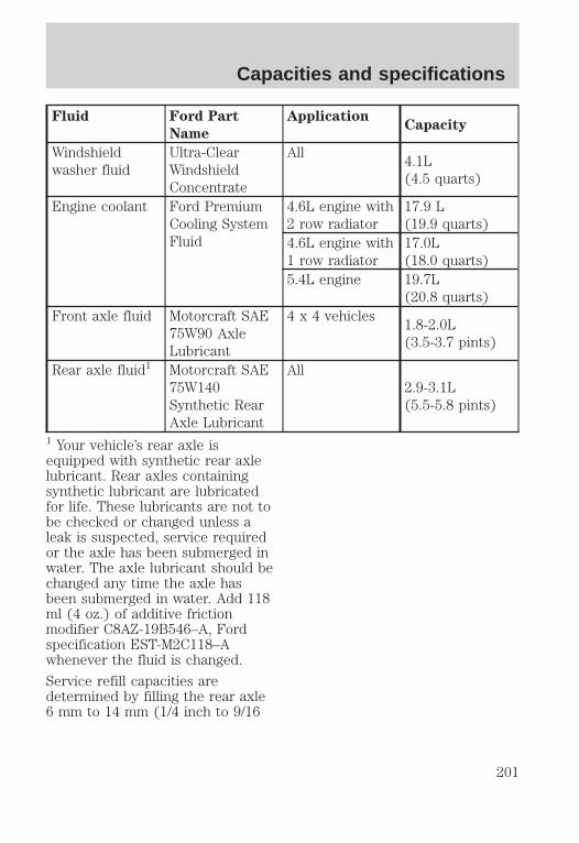
Fluid Ford Part
Name
ApplicationCapacity
Windshieldwasher fluid
Ultra-ClearWindshieldConcentrate
All4.1L(4.5 quarts)
Engine coolant Ford PremiumCooling SystemFluid
4.6L engine with2 row radiator
17.9 L(19.9 quarts)
4.6L engine with1 row radiator
17.0L(18.0 quarts)
5.4L engine 19.7L(20.8 quarts)
Front axle fluid Motorcraft SAE75W90 AxleLubricant
4 x 4 vehicles1.8-2.0L(3.5-3.7 pints)
Rear axle fluid1 Motorcraft SAE75W140Synthetic RearAxle Lubricant
All2.9-3.1L(5.5-5.8 pints)
1 Your vehicle’s rear axle isequipped with synthetic rear axlelubricant. Rear axles containingsynthetic lubricant are lubricatedfor life. These lubricants are not tobe checked or changed unless aleak is suspected, service requiredor the axle has been submerged inwater. The axle lubricant should bechanged any time the axle hasbeen submerged in water. Add 118ml (4 oz.) of additive frictionmodifier C8AZ-19B546–A, Fordspecification EST-M2C118–Awhenever the fluid is changed.
Service refill capacities aredetermined by filling the rear axle6 mm to 14 mm (1/4 inch to 9/16
Capacities and specifications
201

inch) below the bottom of the fillerhole.
LUBRICANT SPECIFICATIONS
ItemFord part
name
Ford part
number
Ford
specification
Windshieldwasher fluidreservoir
Ultra-ClearWindshieldWasherConcentrate
C9AZ-19550-ACOR -BC
ESR-M17P5
Body hinges,latches, doorstriker platesand rotors, seattracks, fuel fillerdoor hinge andspring, hoodlatch, auxiliarylatch
Multi-PurposeGrease
D7AZ-19584-AAORDOAZ-19584-AA
ESR-M1C159-AORESB-M1C93-B
Lock cylinders,swing-awayspare tire carrierpadlock
PenetratingLubricant
E8AZ-19A501-B NONE
Brake mastercylinder
HighPerformanceDOT 3 MotorVehicle BrakeFluid
C6AZ-19542-AB ESA-M6C25-AAND DOT 3
Driveshaft, slipspline, doubleCardan jointcenter ball
Premium LongLife Grease
XG-1-C orXG-1-K
ESA-M1C75-B
Engine coolant Ford PremiumCooling SystemFluid
E2FZ-195490-AA ESE-M97B44-A
Capacities and specifications
202

ItemFord part
name
Ford part
number
Ford
specification
Engine oil Motorcraft 5W30Super PremiumMotor Oil
XO-5W30-QSP WSS-M2C153-Gwith APICertificationMark
4x4 front wheelbearings, 4x4spindle needlebearings, spindlethrust bearings& front driveaxle u-joint/slipspline
HighTemperature4x4 Front Axle& Wheel BearingGrease
E8TZ-19590-A ESA-M1C198-A
Automatictransmission(E4OD)
MotorcraftMERCONt ATF
XT-2-QDX MERCONt
Automatictransmission(4R70W)
MotorcraftMERCONt VATF
XT-5-QMWSS-M2C202-B
Power steeringreservoir
Premium PowerSteering Fluid
E6AZ-19582-AA ESW-M2C33-F
Rear axle1 Motorcraft SAE75W140 HighPerformanceSynthetic RearAxle Lube
F1TZ-19580-B WSL-M2C192-A
Front axle 75W90 GearLube
F1TZ-19C547-MA WSL-M2C192-A
Transfer case -Four wheeldrive
MotorcraftMERCONt ATF
XT-2-QDX MERCONt
1 Add 118 ml (4 oz.) ofEST-M2C118–A (friction modifierPart No. C8AZ-19B546–A) for
Capacities and specifications
203

complete refill of FordTraction-Lok rear axles.
ENGINE DATA
Engine 4.6L engine 5.4L engine
Cubic inches 281 330Horsepower 215 @ 4400 rpm 230 @ 4250 rpmTorque 290 lb. ft. @ 3250 rpm 325 lb. ft. @ 3000 rpmRequired fuel grade 87 octane 87 octaneFiring order 1-3-7-2-6-5-4-8 1-3-7-2-6-5-4-8Spark plug gap 1.3-1.4 mm
(0.052-.056 inch)1.3-1.4 mm(0.052-.056 inch)
Ignition system EDIS Coil on plugCompression ratio 9.0:1 9.0:1
VEHICLE DIMENSIONS
Dimensions mm (in.)
(1) Overall length 5 196 (204.6)(2) Overall width 2 027 (79.8)
(3) Maximum height 4x2/4x4 1 969.8 (77.6)/2 043 (80.4)(4) Wheelbase 3 023 (119.0)(5) Front track 1 661 (65.4)
Capacities and specifications
204

4
1
3
5
2
Capacities and specifications
205

IDENTIFYING YOUR VEHICLE
Safety compliance label
The National Highway TrafficSafety Administration Regulationsrequire that a Safety ComplianceCertification Label be affixed to avehicle and prescribe where theSafety Compliance CertificationLabel may be located. The SafetyCompliance Certification Label islocated on the front door latchpillar on the driver’s side.
Vehicle identification number
The vehicle identification numberis attached to a metal tag and islocated on the driver sideinstrument panel.
Engine numberThe engine number (the last eightnumbers of the vehicleidentification number) is stampedon the engine block, transmission,frame and transfer case (if soequipped).
MFD. BY FORD MOTOR CO. IN U.S.A.
EXT PNT: XXXXXX XXXXXX RC: XX DSO: XXXX F0000BAR INT TR TP/PS R AXLE TR SPR T0000 X XX XXX X XX X XXXX
UTC ∇FOHT-15294A10-GA
MAXIMUM LOAD=OCCUPANTS + LUGGAGE=XXXKG/XXXXLBOCCUPANTS: X TOTAL X FR X 2ND X RR OCCUPANTS LUGGAGE
XX XXXKG/XXXXLBTIRE: XXXX/XXXXX XXX X XXXKG/XXXXLBPRESSURE (FR) XXX kPa/33 PSI COLDPRESSURE (RR) XXX kPa/33 PSI COLDTRAILER TOWING - SEE OWNER GUIDE
DATE: XXXXX GVWR:XXXXX LB/ XXXXX KG
VIN: XXXXXXXXXXXXXXXXX TYPE: XXXXXXXXXXXXXXX
FGAWR: XXXXXX/XXXXXXX RGAWR: XXXXXXX/XXXXXXXTHIS VEHICLE CONFORMS TO ALL APPLICABLE FEDERALMOTOR VEHICLE SAFETY STANDARDS IN EFFECT ON THEDATE OF MANUFACTURE SHOWN ABOVE.
XXXXXXXXXXXXXXXXX
AIR BAG
Capacities and specifications
206

REPORTING SAFETY DEFECTS(U.S. ONLY)
If you believe that your vehicle hasa defect that could cause a crash,or could cause injury or death, youshould immediately inform theNational Highway Traffic SafetyAdministration (NHTSA) inaddition to notifying Ford MotorCompany.
If NHTSA receives similarcomplaints, it may open aninvestigation, and if it finds that asafety defect exists in a group ofvehicles, it may order a recall andremedy campaign. However,NHTSA cannot become involved inindividual problems between you,your dealer or Ford MotorCompany.
To contact NHTSA, you may eithercall the Auto Safety Hotlinetoll-free at 1–800–424–9393(202–366–0123 in the WashingtonD.C. area) or write to:
NHTSA
U.S. Department of Transportation
400 Seventh Street
Washington D.C. 20590
You can also obtain otherinformation about motor vehiclesafety from the Hotline.
Reporting safety defects
207

Aiming headlamps ....................193Air bag supplemental restraintsystem ..........................................78
and child safety seats ..............80description ................................79disposal ......................................83indicator light ...........................82passenger air bag .....................81
Air cleaner filter .......................170Air conditioning
auxiliary heater and airconditioner ................................29manual heating and airconditioning system ..23,24,26,28
Air suspensiondescription ..............................102warning light .............................11
Ambulance packages ....................3Anti-lock brake system (ABS)
description ................................99Battery .......................................168
voltage gauge ............................16Brake fluid
checking and adding ..............157Brakes ..........................................98
anti-lock .....................................98anti-lock brake system (ABS)warning light .............................99fluid, checking and adding ....157
Brake-shift interlock .................104Break-in period .............................2Bulbs, replacing ........................186
headlamps ...............................187rear lamps ........................191,192
Changing a tire .........................138Child safety seats ........................86Childproof locks ..........................50Chime
headlamps on ............................13Cleaning your vehicle ...............194
engine compartment ..............195fabric ........................................197
instrument panel ....................197plastic parts ............................196safety belts ..............................197tail lamps .................................196washing ....................................194waxing .....................................194wheels ......................................195
Compass, electronic ....................42calibration .................................44set zone adjustment .................43
Control trac 4WD system .........108Controls ..................................51,52Daytime running light system ...20Defrost
rear window ..............................22Driving under specialconditions ..................................111
high water ...............................112slippery roads ..................113,114
Electronic sound system ............52Emission control system ..........183Engine ........................................204
check engine temperaturewarning, message center .......152service points ..........................152
Engine block heater ...................96Engine coolant
checking and adding .......158,159disposal ....................................161refill capacities ........................161
Engine oil ...........................153,155changing oil and oil filter .......156checking and adding .......153,155
Exhaust fumes ............................96Fail safe cooling ........................162Floor mats ...................................53Foglamps ...................................190Four-Wheel Drive vehicles
control trac ........................23,108indicator light ...........................11special drivinginstructions ......................109,110
Index
208

Fuelcalculating fuel economy .......182improving fuel economy ........126octane rating ...........................180quality ......................................180safety information relating toautomotive fuels .....................177
Fuel gauge ...................................13Fuel pump shut-off switch .......127Fuse panels
instrument panel ....................129power distribution box ....133,137
Fuses ............................128,129,136Gauges, Mechanical ....................13
engine coolant temperaturegauge .........................................14
Hazard flashers .........................127Head restraints ...........................63Headlamps
autolamp system .......................21flashing ......................................39high beam .................................39turning on and off ....................20
Heating ........................................23High beams
indicator light .............................9Hood
release lever ............................152Ignition
positions of the ignition ...........32Instrument panel
lighting up panel and interior .21Jump-starting your vehicle 145,147
attaching cables ......................146disconnecting cables ..............147
Keyskey in ignition chime ...............13
Lampsinterior lamps .........................193map lamps ...............................193parking lamps .........................189
Liftgate ........................................53
Lights, warning and indicatorair bag ..........................................8anti-lock brakes (ABS) ..............9anti-theft ...................................10brake ............................................9charging system ........................10check engine ............................6,7door ajar ....................................12engine oil pressure ...................10four-wheel drive ........................11fuel reset ................................6,12safety belt ...................................8turn signal indicator ...................9
Load limitstrailer towing ..........................117
Lubricant specifications ...........202Luggage rack .............................126Message center ......................16,42
english/metric button ...............17menu button .............................17
Mirrorsautomatic dimming rearviewmirror ........................................46heated ........................................51side view mirrors (power) .......50
Moon roof ....................................42Odometer .....................................15Off road driving, 4-wheel drive 110Overdrive ................................39,40Overhead console
compass/temperature display ..40storage compartment ...............41
Panic alarm feature, remoteentry system ................................56Parking brake ............................100Parts (see Motorcraft parts) ....200Power door locks ........................48Power steering
fluid, checking and adding ....163Rear window
wiper ..........................................38Refill capacities for fluids ........200
Index
209

Relays .................................128,136Remote entry system .................55
illuminated entry ......................58locking/unlocking doors ......55,56replacement/additionaltransmitters ...............................58replacing the batteries .............57
Reporting safety defects ..........207Safety restraints
automatic locking mode(retractor) .......................72,73,74extension assembly ..................76for children ...............................83lap and shoulder belts ........71,72maintenance ..............................77proper use .................................70warning light and chime 12,76,77
Safety seats for childrenattaching with tether straps ....90automatic locking mode(retractor) .................................87tether anchorage hardware .....90
Seats ............................................60adjusting the seat, manual .......60adjusting the seat, power ........61lumbar support .........................60rear flip fold seat .................63,64rear seat access ........................63reclining the seat ......................65third row seat ............65,66,67,68
Servicing your vehicle ..............150precautions when servicing ...150
Side mirrors .................................51Snowplowing .................................3Special notice
utility-type vehicles ....................3Specification chart, lubricants .202Speed control ..............................33
canceling a set speed ...............36resuming a set speed ...............37tap up/tap down .......................35turning off .................................33
Speed sensitive steering ..........101Speedometer ...............................14Starting your vehicle ........92,93,95Steering, power .........................101Storage compartments
overhead storagecompartment .............................40
Tachometermechanical cluster ...................15
Tilt steering wheel ......................37Tires ....................................172,174
checking the pressure ............174replacing ..................................176rotating ....................................175snow tires and chains ............176treadwear ................................173
Traction-lok rear axle ........103,167Trailer towing
calculating maximum trailerweight ......................................119tips ...........................................124
Transmission .............................164automaticoperation ............104,105,106,107fluid, checking and adding(automatic) .............................164
Trip odometer .............................15Turn signal
lever ...........................................32Vehicle dimensions ...................204Vehicle Identification Number(VIN) ..........................................206Vehicle loading ..........................115Ventilating your vehicle .............97Warning chimes .............................6Washer fluid
rear window reservoir ............158warning light .............................12
Windowsaccessory delay .........................48power windows, operating ..45,47
Index
210

Windshield washer fluid andwipers
checking and adding fluid .....158checking and replacing wiperblades ......................................171operation ...................................38
Wrecker towing .....................148
Index
211

212

213

214

215

Recommended fuel Unleaded fuel only - 87 octaneFuel tank capacity-4x2 without airsuspension
98.0L (26 gallons)
Fuel tank capacity-4x2 vehicleswith air suspension and 4x4vehicles
114.0L (30 gallons)
Engine oil (with filter change) Use Motorcraft 5W30 SuperPremium Motor Oil, FordSpecification WSS-M2C153-G
Tire size and pressure Refer to Tire Pressure Decal onpassenger’s door panel
Hood release Pull handle under the left side ofthe instrument panel
Oil capacity (with filter change) 5.7L (6.0 quarts)Coolant capacity 19.7L (20.8 quarts)Power steering fluid capacity Fill to line in reservoirAutomatic transmission fluidcapacity-4R70W
13.1L (13.9 quarts)
Automatic transmission fluidcapacity-E4OD (4x2)
15.0L (15.9 quarts)
Automatic transmission fluidcapacity-E4OD (4x4)
15.5L (16.4 quarts)
Filling station information
216