976-22 and 980-22 Hydraulic Power Pumps · tools: 976-22 Hydraulic Power Pump (Serial Code YD) ......
22
SERVICE MANUAL 99945940 REV 3 © 2005 Greenlee Textron Inc. 12/05 Read and understand all of the instructions and safety information in this manual before operating or servicing this tool. 976-22 and 980-22 Hydraulic Power Pumps Serial Codes YD and ABZ
-
Upload
phungkhuong -
Category
Documents
-
view
221 -
download
0
Transcript of 976-22 and 980-22 Hydraulic Power Pumps · tools: 976-22 Hydraulic Power Pump (Serial Code YD) ......
SERVICE MANUAL
99945940 REV 3 © 2005 Greenlee Textron Inc. 12/05
Read and understand all of the instructions andsafety information in this manual before operatingor servicing this tool.
976-22 and 980-22Hydraulic Power Pumps
Serial Codes YD and ABZ
Greenlee / A Textron Company 2 4455 Boeing Dr. • Rockford, IL 61109-2988 USA • 815-397-7070
976-22 and 980-22 Hydraulic Power Pumps
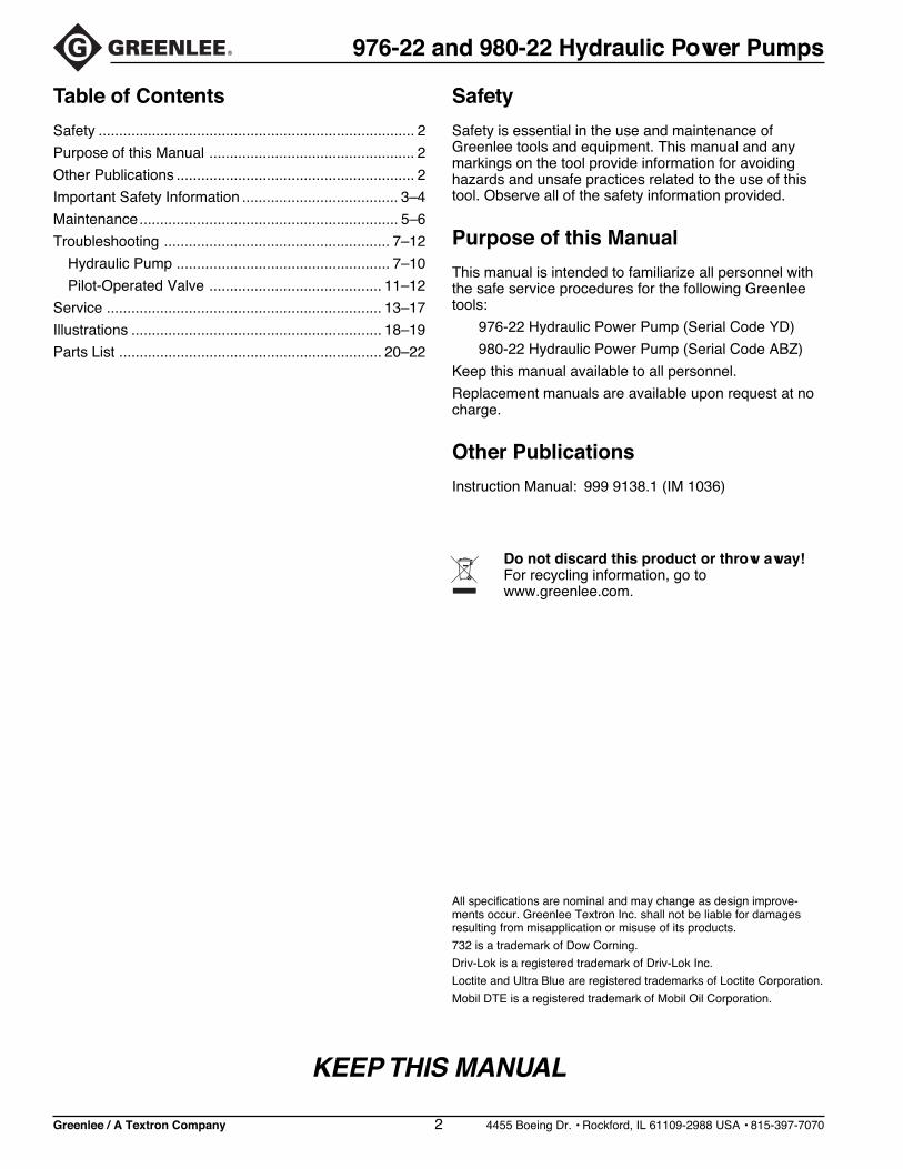
Table of Contents
Safety ............................................................................. 2
Purpose of this Manual .................................................. 2
Other Publications .......................................................... 2
Important Safety Information ...................................... 3–4
Maintenance............................................................... 5–6
Troubleshooting ....................................................... 7–12
Hydraulic Pump .................................................... 7–10
Pilot-Operated Valve .......................................... 11–12
Service ................................................................... 13–17
Illustrations ............................................................. 18–19
Parts List ................................................................ 20–22
All specifications are nominal and may change as design improve-ments occur. Greenlee Textron Inc. shall not be liable for damagesresulting from misapplication or misuse of its products.
732 is a trademark of Dow Corning.
Driv-Lok is a registered trademark of Driv-Lok Inc.
Loctite and Ultra Blue are registered trademarks of Loctite Corporation.
Mobil DTE is a registered trademark of Mobil Oil Corporation.
KEEP THIS MANUAL
Safety
Safety is essential in the use and maintenance ofGreenlee tools and equipment. This manual and anymarkings on the tool provide information for avoidinghazards and unsafe practices related to the use of thistool. Observe all of the safety information provided.
Purpose of this Manual
This manual is intended to familiarize all personnel withthe safe service procedures for the following Greenleetools:
976-22 Hydraulic Power Pump (Serial Code YD)
980-22 Hydraulic Power Pump (Serial Code ABZ)
Keep this manual available to all personnel.
Replacement manuals are available upon request at nocharge.
Other Publications
Instruction Manual: 999 9138.1 (IM 1036)
Do not discard this product or throw away!For recycling information, go towww.greenlee.com.
Greenlee / A Textron Company 3 4455 Boeing Dr. • Rockford, IL 61109-2988 USA • 815-397-7070
976-22 and 980-22 Hydraulic Power Pumps
IMPORTANT SAFETY INFORMATION
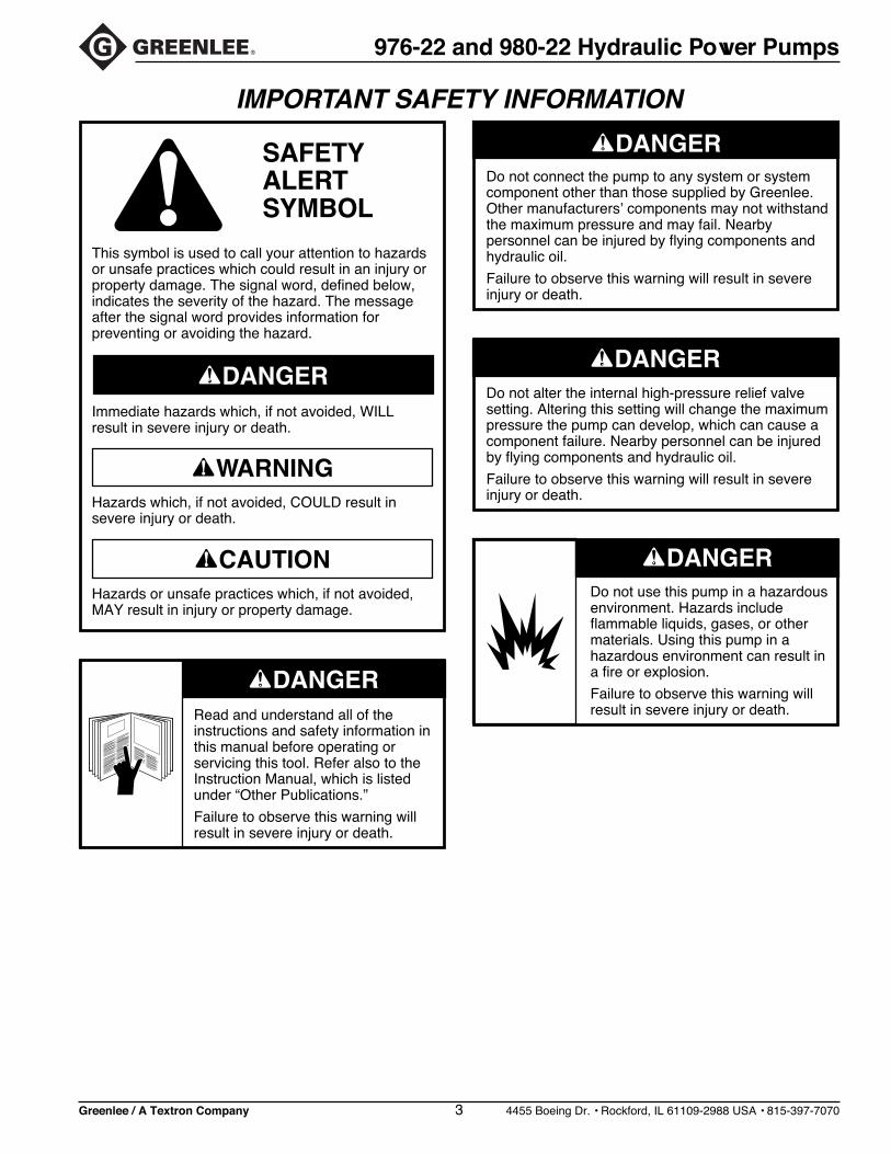
Read and understand all of theinstructions and safety information inthis manual before operating orservicing this tool. Refer also to theInstruction Manual, which is listedunder “Other Publications.”
Failure to observe this warning willresult in severe injury or death.
Do not use this pump in a hazardousenvironment. Hazards includeflammable liquids, gases, or othermaterials. Using this pump in ahazardous environment can result ina fire or explosion.
Failure to observe this warning willresult in severe injury or death.
This symbol is used to call your attention to hazardsor unsafe practices which could result in an injury orproperty damage. The signal word, defined below,indicates the severity of the hazard. The messageafter the signal word provides information forpreventing or avoiding the hazard.
Hazards or unsafe practices which, if not avoided,MAY result in injury or property damage.
Hazards which, if not avoided, COULD result insevere injury or death.
Immediate hazards which, if not avoided, WILLresult in severe injury or death.
SAFETYALERTSYMBOL
Do not alter the internal high-pressure relief valvesetting. Altering this setting will change the maximumpressure the pump can develop, which can cause acomponent failure. Nearby personnel can be injuredby flying components and hydraulic oil.
Failure to observe this warning will result in severeinjury or death.
Do not connect the pump to any system or systemcomponent other than those supplied by Greenlee.Other manufacturers’ components may not withstandthe maximum pressure and may fail. Nearbypersonnel can be injured by flying components andhydraulic oil.
Failure to observe this warning will result in severeinjury or death.
Greenlee / A Textron Company 4 4455 Boeing Dr. • Rockford, IL 61109-2988 USA • 815-397-7070
976-22 and 980-22 Hydraulic Power Pumps
IMPORTANT SAFETY INFORMATION
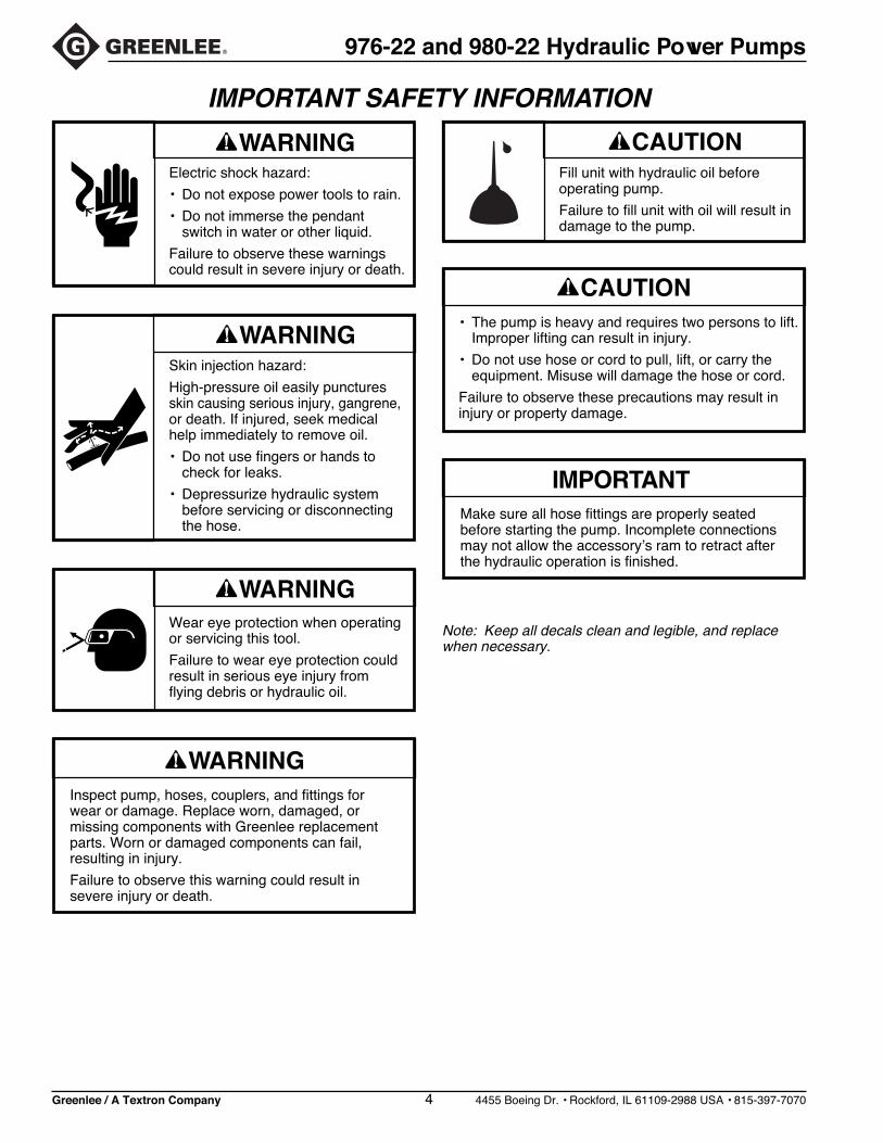
Note: Keep all decals clean and legible, and replacewhen necessary.
Inspect pump, hoses, couplers, and fittings forwear or damage. Replace worn, damaged, ormissing components with Greenlee replacementparts. Worn or damaged components can fail,resulting in injury.
Failure to observe this warning could result insevere injury or death.
• The pump is heavy and requires two persons to lift.Improper lifting can result in injury.
• Do not use hose or cord to pull, lift, or carry theequipment. Misuse will damage the hose or cord.
Failure to observe these precautions may result ininjury or property damage.
Make sure all hose fittings are properly seatedbefore starting the pump. Incomplete connectionsmay not allow the accessory’s ram to retract afterthe hydraulic operation is finished.
Electric shock hazard:
• Do not expose power tools to rain.
• Do not immerse the pendantswitch in water or other liquid.
Failure to observe these warningscould result in severe injury or death.
Skin injection hazard:
High-pressure oil easily puncturesskin causing serious injury, gangrene,or death. If injured, seek medicalhelp immediately to remove oil.
• Do not use fingers or hands tocheck for leaks.
• Depressurize hydraulic systembefore servicing or disconnectingthe hose.
Wear eye protection when operatingor servicing this tool.
Failure to wear eye protection couldresult in serious eye injury fromflying debris or hydraulic oil.
Fill unit with hydraulic oil beforeoperating pump.
Failure to fill unit with oil will result indamage to the pump.

Greenlee / A Textron Company 5 4455 Boeing Dr. • Rockford, IL 61109-2988 USA • 815-397-7070
976-22 and 980-22 Hydraulic Power Pumps
Maintenance
Procedure for depressurizing the hydraulic system:
1. Disconnect the pump from the power source.
2. Rotate the release lever to AUTO RELEASEand allow the ram to retract fully.
3. Disconnect the hose slowly to release anytrapped pressure.
Every Time the Pump Is Used
• Check the oil reservoir level. The oil level should beapproximately 25 mm (1 inch) from the top of thereservoir. If the oil level is low, refer to “Adding Oil” inthis section of the manual.
• Examine the condition of the hose, connectors,and O-rings for deterioration, wear, or other damage.Replace any missing or damaged components.
• Check the condition of all electrical cords, plugs,and connectors.
• Listen for unusual noises and observe the operation ofthe pump for changes in performance. Either situationmay indicate that maintenance or repairs arenecessary.
Periodically
• Examine the hydraulic oil for changes in coloror viscosity, and the presence of dirt or othercontamination.
• Occasionally check the oil temperature after the pumpis operated. The recommended operating temperatureis 38 °C to 50 °C (100 °F to 125 °F).
Cleaning
• Periodically clean the exterior of the pump and motor.Use a vacuum cleaner to clean the ventilationopenings.
• Clean the area around the reservoir vent, and be surethe vent breather hole is open.
• Keep all hose connections clean. Use protective capsor plugs when couplers are not in use.
Oil Condition
Visual inspection of the oil may be used as a guide todetermine the need to replace the oil. A change inappearance, such as darkening or thickening, indicatesa need for replacement. The continued use of oil after itshould be replaced causes accelerated wear of systemcomponents and voids the warranty.
Adding Oil
Refer to the “Parts List” in this manual for Greenleehydraulic oil specification and Greenlee part number.
1. Place the control lever in the AUTO RELEASEposition.
2. Unplug the electrical cord from the power source.
3. Thoroughly clean the area around the fill hole.
4. Remove the vented reservoir plug.
5. Use Greenlee hydraulic fluid or an equivalent high-grade light hydraulic oil.
6. Pour the oil through a clean funnel with a filterscreen.
7. Add oil until the oil level is 25 mm (1 inch) from thetop of the reservoir cover.
Do not use brake fluid. Brake fluid will ruin the seals.
Greenlee / A Textron Company 6 4455 Boeing Dr. • Rockford, IL 61109-2988 USA • 815-397-7070
976-22 and 980-22 Hydraulic Power Pumps
Draining and Flushing the System
Note: Thoroughly clean the pump exterior beforeremoving the reservoir.
1. Remove the reservoir cover screws.
2. Remove the pump system from the reservoir.Note: Be careful not to damage the cover gasket,inlet strainer, or relief valve when removing thepump.
3. Clean the interior of the reservoir and fill with cleankerosene. Do not use solvents. Rinse the inletstrainer.
4. Place the pump system into the reservoir andreplace the four cover screws.
5. Connect a hose to the pump as usual. Insertthe other end of the hose into the pump reservoirat the fill hole.
6. Run the pump for several minutes. While the pumpis running, rotate the control lever betweenMANUAL RELEASE and AUTO RELEASE severaltimes. Start and stop the pump several times tocycle the pilot-operated valve.
7. Remove the hose and remove the pump assemblyfrom the reservoir. Drain and clean the reservoirinterior. Allow the reservoir to dry. Drain the hose.
8. Reassemble the pump system.
9. Refill the reservoir as instructed under “Adding Oil”in this section of the manual.
Motor Maintenance
Disconnect the pump from the power source beforeservicing or cleaning the motor. The exposed motorbearings and shaft should be cleaned periodically.
Lubrication
Lubricate the motor according the motor manufacturer’sinstructions, which are on the nameplate or the terminalbox cover.
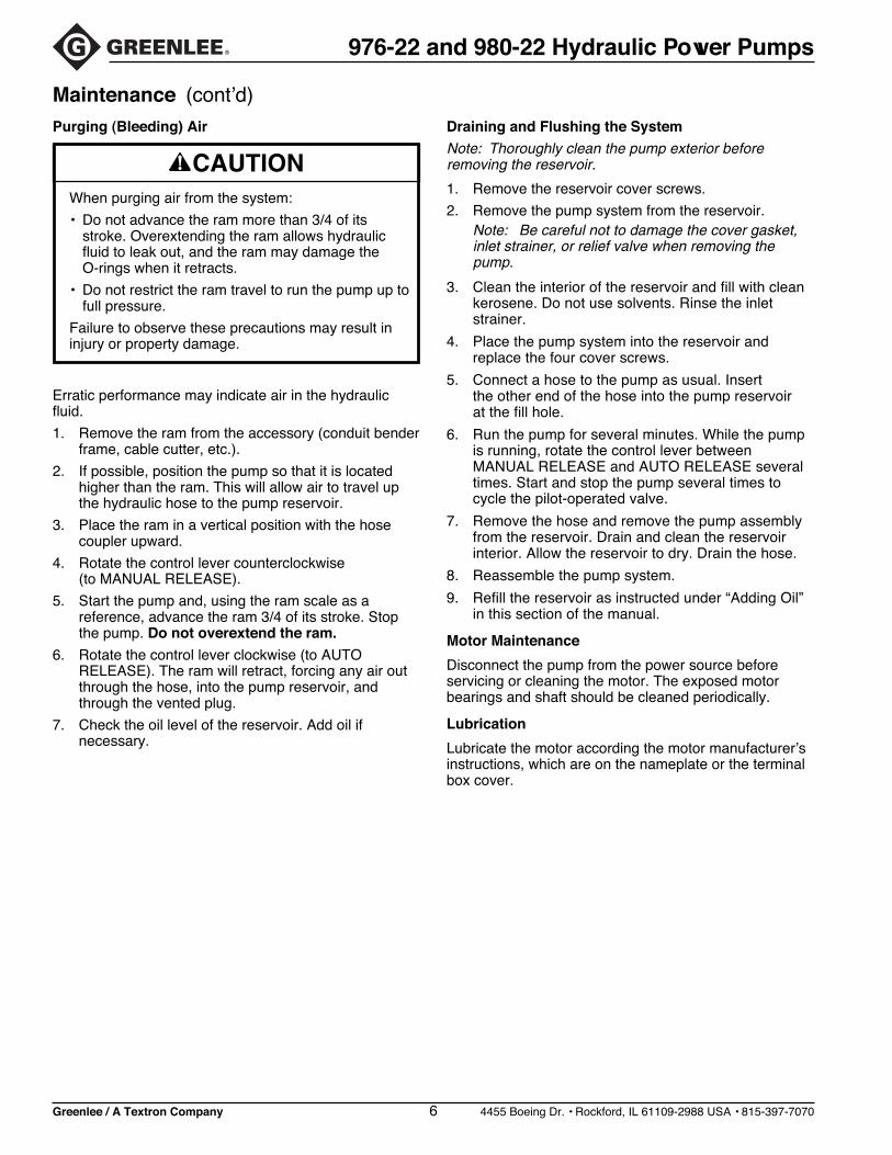
Maintenance (cont’d)
Erratic performance may indicate air in the hydraulicfluid.
1. Remove the ram from the accessory (conduit benderframe, cable cutter, etc.).
2. If possible, position the pump so that it is locatedhigher than the ram. This will allow air to travel upthe hydraulic hose to the pump reservoir.
3. Place the ram in a vertical position with the hosecoupler upward.
4. Rotate the control lever counterclockwise(to MANUAL RELEASE).
5. Start the pump and, using the ram scale as areference, advance the ram 3/4 of its stroke. Stopthe pump. Do not overextend the ram.
6. Rotate the control lever clockwise (to AUTORELEASE). The ram will retract, forcing any air outthrough the hose, into the pump reservoir, andthrough the vented plug.
7. Check the oil level of the reservoir. Add oil ifnecessary.
Purging (Bleeding) Air
When purging air from the system:
• Do not advance the ram more than 3/4 of itsstroke. Overextending the ram allows hydraulicfluid to leak out, and the ram may damage theO-rings when it retracts.
• Do not restrict the ram travel to run the pump up tofull pressure.
Failure to observe these precautions may result ininjury or property damage.
Greenlee / A Textron Company 7 4455 Boeing Dr. • Rockford, IL 61109-2988 USA • 815-397-7070
976-22 and 980-22 Hydraulic Power Pumps
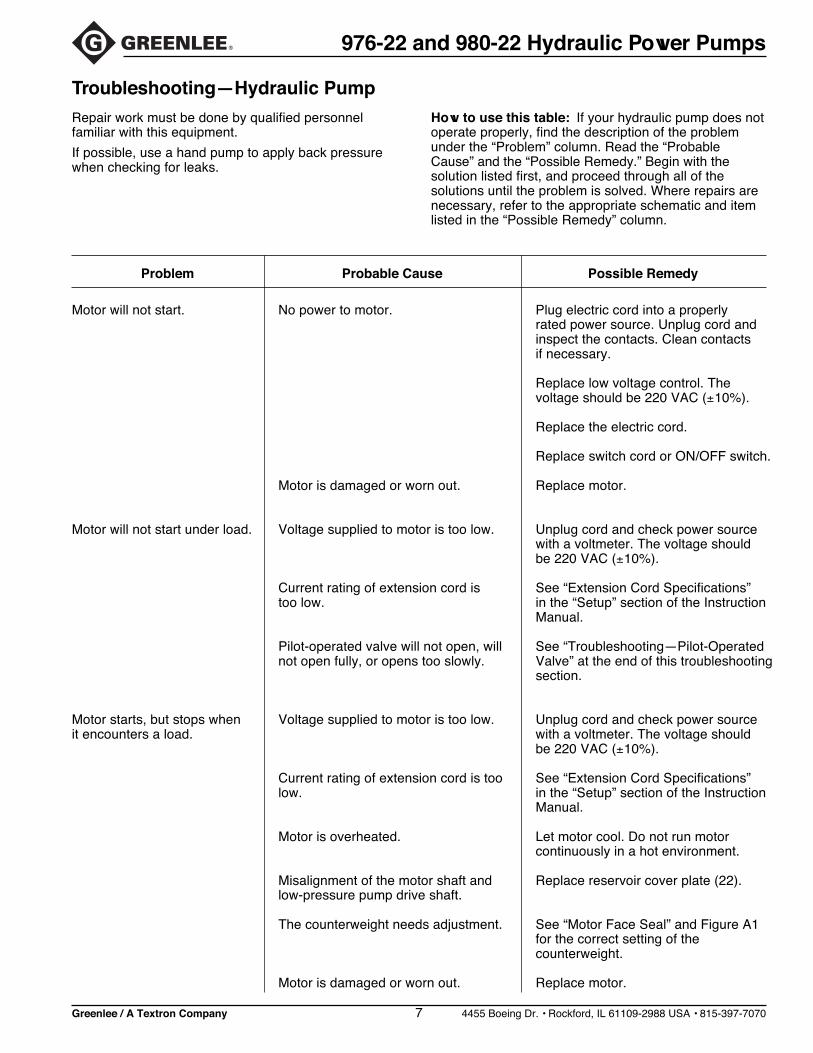
Motor will not start. No power to motor. Plug electric cord into a properlyrated power source. Unplug cord andinspect the contacts. Clean contactsif necessary.
Replace low voltage control. Thevoltage should be 220 VAC (±10%).
Replace the electric cord.
Replace switch cord or ON/OFF switch.
Motor is damaged or worn out. Replace motor.
Motor will not start under load. Voltage supplied to motor is too low. Unplug cord and check power sourcewith a voltmeter. The voltage shouldbe 220 VAC (±10%).
Current rating of extension cord is See “Extension Cord Specifications”too low. in the “Setup” section of the Instruction
Manual.
Pilot-operated valve will not open, will See “Troubleshooting—Pilot-Operatednot open fully, or opens too slowly. Valve” at the end of this troubleshooting
section.
Motor starts, but stops when Voltage supplied to motor is too low. Unplug cord and check power sourceit encounters a load. with a voltmeter. The voltage should
be 220 VAC (±10%).
Current rating of extension cord is too See “Extension Cord Specifications”low. in the “Setup” section of the Instruction
Manual.
Motor is overheated. Let motor cool. Do not run motorcontinuously in a hot environment.
Misalignment of the motor shaft and Replace reservoir cover plate (22).low-pressure pump drive shaft.
The counterweight needs adjustment. See “Motor Face Seal” and Figure A1for the correct setting of thecounterweight.
Motor is damaged or worn out. Replace motor.
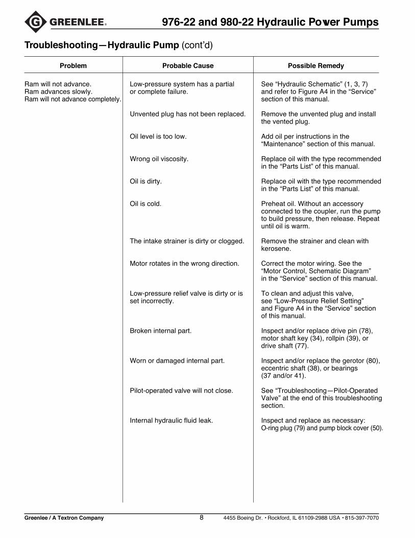
Troubleshooting—Hydraulic Pump
Repair work must be done by qualified personnelfamiliar with this equipment.
If possible, use a hand pump to apply back pressurewhen checking for leaks.
How to use this table: If your hydraulic pump does notoperate properly, find the description of the problemunder the “Problem” column. Read the “ProbableCause” and the “Possible Remedy.” Begin with thesolution listed first, and proceed through all of thesolutions until the problem is solved. Where repairs arenecessary, refer to the appropriate schematic and itemlisted in the “Possible Remedy” column.
Probable CauseProblem Possible Remedy
Greenlee / A Textron Company 8 4455 Boeing Dr. • Rockford, IL 61109-2988 USA • 815-397-7070
976-22 and 980-22 Hydraulic Power Pumps
Ram will not advance. Low-pressure system has a partial See “Hydraulic Schematic” (1, 3, 7)Ram advances slowly. or complete failure. and refer to Figure A4 in the “Service”Ram will not advance completely. section of this manual.
Unvented plug has not been replaced. Remove the unvented plug and installthe vented plug.
Oil level is too low. Add oil per instructions in the“Maintenance” section of this manual.
Wrong oil viscosity. Replace oil with the type recommendedin the “Parts List” of this manual.
Oil is dirty. Replace oil with the type recommendedin the “Parts List” of this manual.
Oil is cold. Preheat oil. Without an accessoryconnected to the coupler, run the pumpto build pressure, then release. Repeatuntil oil is warm.
The intake strainer is dirty or clogged. Remove the strainer and clean withkerosene.
Motor rotates in the wrong direction. Correct the motor wiring. See the“Motor Control, Schematic Diagram”in the “Service” section of this manual.
Low-pressure relief valve is dirty or is To clean and adjust this valve,set incorrectly. see “Low-Pressure Relief Setting”
and Figure A4 in the “Service” sectionof this manual.
Broken internal part. Inspect and/or replace drive pin (78),motor shaft key (34), rollpin (39), ordrive shaft (77).
Worn or damaged internal part. Inspect and/or replace the gerotor (80),eccentric shaft (38), or bearings(37 and/or 41).
Pilot-operated valve will not close. See “Troubleshooting—Pilot-OperatedValve” at the end of this troubleshootingsection.
Internal hydraulic fluid leak. Inspect and replace as necessary:O-ring plug (79) and pump block cover (50).
Troubleshooting—Hydraulic Pump (cont’d)
Probable CauseProblem Possible Remedy

Greenlee / A Textron Company 9 4455 Boeing Dr. • Rockford, IL 61109-2988 USA • 815-397-7070
976-22 and 980-22 Hydraulic Power Pumps
Troubleshooting—Hydraulic Pump (cont’d)
Ram advances erratically Air in the hydraulic fluid. Refer to “Purging (Bleeding) Air” in theand retracts erratically. “Maintenance” section of this manual.
Pump will not build enough High-pressure system is faulty. See “Hydraulic Schematic” (5) and referpressure to complete the job. to Figure A5-1 in the “Service” sectionRam advances slowly. of this manual.
System has an external hydraulic leak. Visually inspect hoses, connectors,and fittings for leaking hydraulic fluid.Replace faulty components.
Pilot-operated valve will not close. See “Troubleshooting—Pilot-OperatedValve” at the end of this troubleshootingsection.
Low-pressure system is at fault. Find “Low-pressure system has a partialor complete failure” under “ProbableCause” in this troubleshooting section.
At high-pressure inlet, the check ball See “Check Ball Travel at High-Pressurehas too much travel. Inlet” and Figure A5-1. If the seats are
leaking, see “Ball Seat Refinishing”and Figure B2 in the “Service” sectionof this manual.
The high-pressure piston is stuck. Disassemble, clean, and inspect thehigh-pressure bushing (75) andhigh-pressure piston (76). Replaceparts as necessary.
Internal hydraulic fluid leak. Inspect and replace as necessary:O-ring plug (68)Cavity insert (74)High-pressure bushing (75)High-pressure relief valve (72)
High-pressure relief valve failure. Readjust, re-seat, or replace valve (72).
Probable CauseProblem Possible Remedy
Greenlee / A Textron Company 10 4455 Boeing Dr. • Rockford, IL 61109-2988 USA • 815-397-7070
976-22 and 980-22 Hydraulic Power Pumps
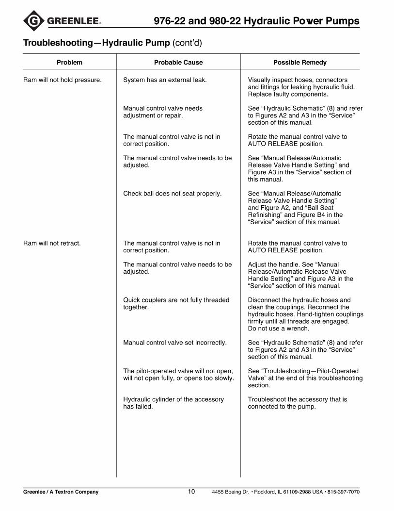
Troubleshooting—Hydraulic Pump (cont’d)
Ram will not hold pressure. System has an external leak. Visually inspect hoses, connectorsand fittings for leaking hydraulic fluid.Replace faulty components.
Manual control valve needs See “Hydraulic Schematic” (8) and referadjustment or repair. to Figures A2 and A3 in the “Service”
section of this manual.
The manual control valve is not in Rotate the manual control valve tocorrect position. AUTO RELEASE position.
The manual control valve needs to be See “Manual Release/Automaticadjusted. Release Valve Handle Setting” and
Figure A3 in the “Service” section ofthis manual.
Check ball does not seat properly. See “Manual Release/AutomaticRelease Valve Handle Setting”and Figure A2, and “Ball SeatRefinishing” and Figure B4 in the“Service” section of this manual.
Ram will not retract. The manual control valve is not in Rotate the manual control valve tocorrect position. AUTO RELEASE position.
The manual control valve needs to be Adjust the handle. See “Manualadjusted. Release/Automatic Release Valve
Handle Setting” and Figure A3 in the“Service” section of this manual.
Quick couplers are not fully threaded Disconnect the hydraulic hoses andtogether. clean the couplings. Reconnect the
hydraulic hoses. Hand-tighten couplingsfirmly until all threads are engaged.Do not use a wrench.
Manual control valve set incorrectly. See “Hydraulic Schematic” (8) and referto Figures A2 and A3 in the “Service”section of this manual.
The pilot-operated valve will not open, See “Troubleshooting—Pilot-Operatedwill not open fully, or opens too slowly. Valve” at the end of this troubleshooting
section.
Hydraulic cylinder of the accessory Troubleshoot the accessory that ishas failed. connected to the pump.
Probable CauseProblem Possible Remedy
Greenlee / A Textron Company 11 4455 Boeing Dr. • Rockford, IL 61109-2988 USA • 815-397-7070
976-22 and 980-22 Hydraulic Power Pumps
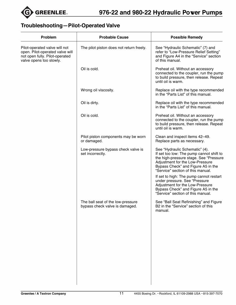
Troubleshooting—Pilot-Operated Valve
Pilot-operated valve will not The pilot piston does not return freely. See “Hydraulic Schematic” (7) andopen. Pilot-operated valve will refer to “Low-Pressure Relief Setting”not open fully. Pilot-operated and Figure A4 in the “Service” sectionvalve opens too slowly. of this manual.
Oil is cold. Preheat oil. Without an accessoryconnected to the coupler, run the pumpto build pressure, then release. Repeatuntil oil is warm.
Wrong oil viscosity. Replace oil with the type recommendedin the “Parts List” of this manual.
Oil is dirty. Replace oil with the type recommendedin the “Parts List” of this manual.
Oil is cold. Preheat oil. Without an accessoryconnected to the coupler, run the pumpto build pressure, then release. Repeatuntil oil is warm.
Pilot piston components may be worn Clean and inspect items 42–49.or damaged. Replace parts as necessary.
Low-pressure bypass check valve is See “Hydraulic Schematic” (4).set incorrectly. If set too low: The pump cannot shift to
the high-pressure stage. See “PressureAdjustment for the Low-PressureBypass Check” and Figure A5 in the“Service” section of this manual.
If set to high: The pump cannot restartunder pressure. See “PressureAdjustment for the Low-PressureBypass Check” and Figure A5 in the“Service” section of this manual.
The ball seat of the low-pressure See “Ball Seat Refinishing” and Figurebypass check valve is damaged. B2 in the “Service” section of this
manual.
Probable CauseProblem Possible Remedy
Greenlee / A Textron Company 12 4455 Boeing Dr. • Rockford, IL 61109-2988 USA • 815-397-7070
976-22 and 980-22 Hydraulic Power Pumps
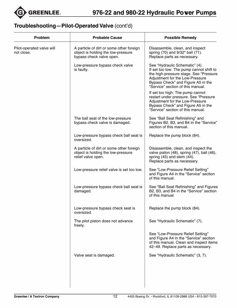
Troubleshooting—Pilot-Operated Valve (cont’d)
Pilot-operated valve will A particle of dirt or some other foreign Disassemble, clean, and inspectnot close. object is holding the low-pressure spring (70) and 9/32" ball (71).
bypass check valve open. Replace parts as necessary.
Low-pressure bypass check valve See “Hydraulic Schematic” (4).is faulty. If set too low: The pump cannot shift to
the high-pressure stage. See “PressureAdjustment for the Low-PressureBypass Check” and Figure A5 in the“Service” section of this manual.
If set too high: The pump cannotrestart under pressure. See “PressureAdjustment for the Low-PressureBypass Check” and Figure A5 in the“Service” section of this manual.
The ball seat of the low-pressure See “Ball Seat Refinishing” andbypass check valve is damaged. Figures B2, B3, and B4 in the “Service”
section of this manual.
Low-pressure bypass check ball seat is Replace the pump block (84).oversized.
A particle of dirt or some other foreign Disassemble, clean, and inspect theobject is holding the low-pressure valve piston (48), spring (47), ball (46),relief valve open. spring (45) and stem (44).
Replace parts as necessary.
Low-pressure relief valve is set too low. See “Low-Pressure Relief Setting”and Figure A4 in the “Service” sectionof this manual.
Low-pressure bypass check ball seat is See “Ball Seat Refinishing” and Figuresdamaged. B2, B3, and B4 in the “Service” section
of this manual.
Low-pressure bypass check seat is Replace the pump block (84).oversized.
The pilot piston does not advance See “Hydraulic Schematic” (7).freely.
See “Low-Pressure Relief Setting”and Figure A4 in the “Service” sectionof this manual. Clean and inspect items42–49. Replace parts as necessary.
Valve seat is damaged. See “Hydraulic Schematic” (3, 7).
Probable CauseProblem Possible Remedy

Greenlee / A Textron Company 13 4455 Boeing Dr. • Rockford, IL 61109-2988 USA • 815-397-7070
976-22 and 980-22 Hydraulic Power Pumps
Service
Motor Control Unit
Motor Control with Cover Removed
Motor Control with Cover Removed, Side View
Motor Control, Schematic Diagram
Foot Switch
Pendant Switch
99
96
97A
98
97
98
97
98100
G
ELECTRONIC MOTOR CONTROLGREENLEETO MOTOR
GRN-GRD
BLK-L1
WHT-L2
94
UNDER PC BOARD
101
95
939193
92
BLACK WIREMOTOR L1
WHITE WIRE
SWITCH CORD POWER CORD
WHITE WIRE L2
WHITE WIREMOTOR L2
BLACK WIRE L1
GREEN WIRE
MOTOR GROUND
BLACK WIRE
Apply ThermalloyThermal Cote 1thermal grease tobottom of relay andsurface of base priorto installation of relay.
92 95
93
101
91
R1 2
4 3
+-
3-32 VDC
REMOTE SWITCHCORD W/PLUG
240 VAC45 AMP
BLACK
WH
ITE
BLACK
BLACK
8
7
6
5
4
1
100 V1 AMP
BLA
CK
GR
EE
N
16 VDC47yF
+
WH
ITE
POWER CORD
WHITE
220 V @ 1.12 VA
GREEN
CONTROL UNIT(COMMON WIRING)
3
2
8 V
BLACK
Wiring Diagram
Switch mountedto guard withtwo #10 screws(supplied with guard).
WHITE C ND
NC
111110109108
85
90
108
8687 89
88
Greenlee / A Textron Company 14 4455 Boeing Dr. • Rockford, IL 61109-2988 USA • 815-397-7070
976-22 and 980-22 Hydraulic Power Pumps
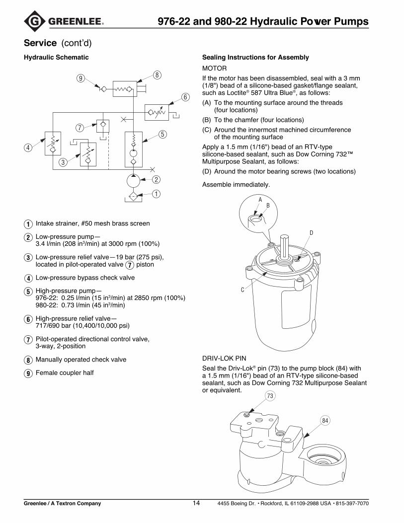
Hydraulic Schematic
1 Intake strainer, #50 mesh brass screen
2 Low-pressure pump—3.4 l/min (208 in3/min) at 3000 rpm (100%)
3 Low-pressure relief valve—19 bar (275 psi),located in pilot-operated valve 7 piston
4 Low-pressure bypass check valve
5 High-pressure pump—976-22: 0.25 l/min (15 in3/min) at 2850 rpm (100%)980-22: 0.73 l/min (45 in3/min)
6 High-pressure relief valve—717/690 bar (10,400/10,000 psi)
7 Pilot-operated directional control valve,3-way, 2-position
8 Manually operated check valve
9 Female coupler half
Service (cont’d)
DRIV-LOK PIN
Seal the Driv-Lok® pin (73) to the pump block (84) witha 1.5 mm (1/16") bead of an RTV-type silicone-basedsealant, such as Dow Corning 732 Multipurpose Sealantor equivalent.
Sealing Instructions for Assembly
MOTOR
If the motor has been disassembled, seal with a 3 mm(1/8") bead of a silicone-based gasket/flange sealant,such as Loctite® 587 Ultra Blue®, as follows:
(A) To the mounting surface around the threads(four locations)
(B) To the chamfer (four locations)
(C) Around the innermost machined circumferenceof the mounting surface
Apply a 1.5 mm (1/16") bead of an RTV-typesilicone-based sealant, such as Dow Corning 732™Multipurpose Sealant, as follows:
(D) Around the motor bearing screws (two locations)
Assemble immediately.
6
8
7
3
4
9
5
2
1A
B
D
C
73
84

Greenlee / A Textron Company 15 4455 Boeing Dr. • Rockford, IL 61109-2988 USA • 815-397-7070
976-22 and 980-22 Hydraulic Power Pumps
The following sections and figures describe pertinentdetails for refinishing ball seats and componentreassembly and adjustments.
Motor Face Seal
When reassembling the motor, refer to Figure A1 for theface seal seating dimension. Also, refer to this figure forsetting the vertical position of counterweight (32).
Manual Release/Automatic ReleaseValve Handle Setting
Refer to Figures A2 and A3.
1. Thread in the shaft (62) until it just touches thecheck ball (55) (in its spring-loaded closed position).
2. Slide collar (104) on the shaft.
3. Position the handle (61) at the location “Position 1”(Figure A3), with the other surface of the handleflush with the end of the shaft. Lock in place.
4. Rotate the handle to “Position 2” (Figure A3).
5. Slide the collar toward the valve body until it contactsthe 15.9 mm (5/8") diameter portion of the controlshaft. Rotate the lock collar clockwise until it touchesthe stop pin, and lock in place.
6. When locking control handle and lock collar in place,torque set screws to 2.8 Nm to 3.4 Nm(25 in-lb to 30 in-lb).
Service (cont’d)
22 21
MOTOR SHAFT
MOTOR FACE
4.6 mm (0.180")4.1 mm (0.160")
326 mm (0.234")
54 5560
62
104
61
7.938 mm (0.312") ø BALL SEAT
STOPPIN
45°
STOPCLOSED
STOPOPEN
BALL OPEN112.5°
(.99 mm [.039"])
POSITION 2
SET POSITION 1
22.5° (REF.)
135°
Figure A1 8
Figure A2 8
Figure A3 8
Greenlee / A Textron Company 16 4455 Boeing Dr. • Rockford, IL 61109-2988 USA • 815-397-7070
976-22 and 980-22 Hydraulic Power Pumps
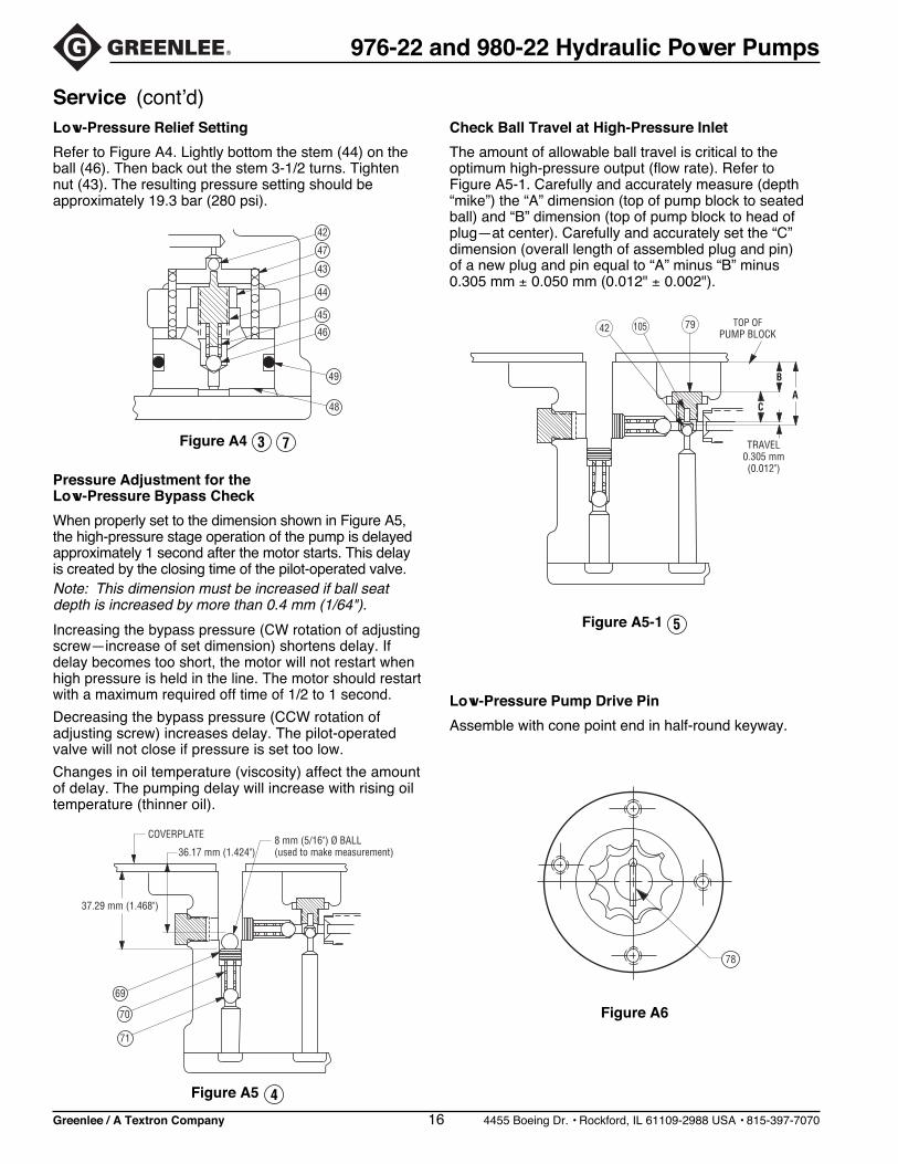
Low-Pressure Relief Setting
Refer to Figure A4. Lightly bottom the stem (44) on theball (46). Then back out the stem 3-1/2 turns. Tightennut (43). The resulting pressure setting should beapproximately 19.3 bar (280 psi).
Service (cont’d)
Pressure Adjustment for theLow-Pressure Bypass Check
When properly set to the dimension shown in Figure A5,the high-pressure stage operation of the pump is delayedapproximately 1 second after the motor starts. This delayis created by the closing time of the pilot-operated valve.Note: This dimension must be increased if ball seatdepth is increased by more than 0.4 mm (1/64").
Increasing the bypass pressure (CW rotation of adjustingscrew—increase of set dimension) shortens delay. Ifdelay becomes too short, the motor will not restart whenhigh pressure is held in the line. The motor should restartwith a maximum required off time of 1/2 to 1 second.
Decreasing the bypass pressure (CCW rotation ofadjusting screw) increases delay. The pilot-operatedvalve will not close if pressure is set too low.
Changes in oil temperature (viscosity) affect the amountof delay. The pumping delay will increase with rising oiltemperature (thinner oil).
Check Ball Travel at High-Pressure Inlet
The amount of allowable ball travel is critical to theoptimum high-pressure output (flow rate). Refer toFigure A5-1. Carefully and accurately measure (depth“mike”) the “A” dimension (top of pump block to seatedball) and “B” dimension (top of pump block to head ofplug—at center). Carefully and accurately set the “C”dimension (overall length of assembled plug and pin)of a new plug and pin equal to “A” minus “B” minus0.305 mm ± 0.050 mm (0.012" ± 0.002").
Low-Pressure Pump Drive Pin
Assemble with cone point end in half-round keyway.
Figure A4 3 7
Figure A5 4
Figure A5-1 5
Figure A6
44
42
47
43
45
46
49
48
COVERPLATE
36.17 mm (1.424")8 mm (5/16") Ø BALL(used to make measurement)
37.29 mm (1.468")
69
70
71
TOP OFPUMP BLOCK
AC
B
TRAVEL0.305 mm(0.012")
42 79105
78
Greenlee / A Textron Company 17 4455 Boeing Dr. • Rockford, IL 61109-2988 USA • 815-397-7070
976-22 and 980-22 Hydraulic Power Pumps
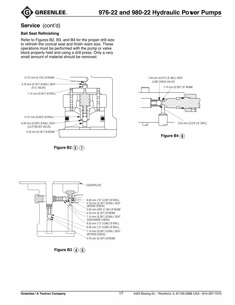
Service (cont’d)Ball Seat Refinishing
Refer to Figures B2, B3, and B4 for the proper drill sizeto refinish the conical seat and finish ream size. Theseoperations must be performed with the pump or valveblock properly held and using a drill press. Only a verysmall amount of material should be removed.
Figure B2 3 7
Figure B3 4 5
Figure B4 8
3.175 mm (0.125") Ø REAM
4.76 mm (0.187") Ø BALL SEAT(P.O. VALVE)
7.14 mm (0.281") Ø DRILL
11.51 mm (0.453") Ø DRILL
6.35 mm (0.250") Ø BALL SEAT(LO-P RELIEF VALVE)
4.76 mm (0.187") Ø REAM
COVERPLATE
8.43 mm (“Q” 0.332") Ø DRILL4.76 mm (0.187") Ø BALL SEAT(INTAKE CHECK)3.45 mm (#29 0.136") Ø REAM4.76 mm (0.187") Ø REAM7.14 mm (0.281") Ø BALL SEAT(DISCHARGE CHECK)9.35 mm (“U” 0.368") Ø DRILL9.35 mm (“U” 0.368") Ø DRILL7.14 mm (0.281") Ø BALL SEAT(BYPASS CHECK)4.76 mm (0.187") Ø REAM
9.53 mm (0.375") Ø DRILL
7.14 mm (0.281") Ø REAM
7.94 mm (0.312") Ø BALL SEAT(LINE CHECK VALVE)

Greenlee / A Textron Company 18 4455 Boeing Dr. • Rockford, IL 61109-2988 USA • 815-397-7070
976-22 and 980-22 Hydraulic Power Pumps
Illustration
19
77
6
12
2 22
1
13
23
21
10
4
16
26
3127
99
2627
31
8
100
34
14
9
2 28
2
3
15
2
1
13
24
2524
25
12
35
17
18
33
32 11
28
11
1
11
1
Figs. A1 and A5
Fig. A2
Fig. A4
SerialNo.
115
116
Greenlee / A Textron Company 19 4455 Boeing Dr. • Rockford, IL 61109-2988 USA • 815-397-7070
976-22 and 980-22 Hydraulic Power Pumps
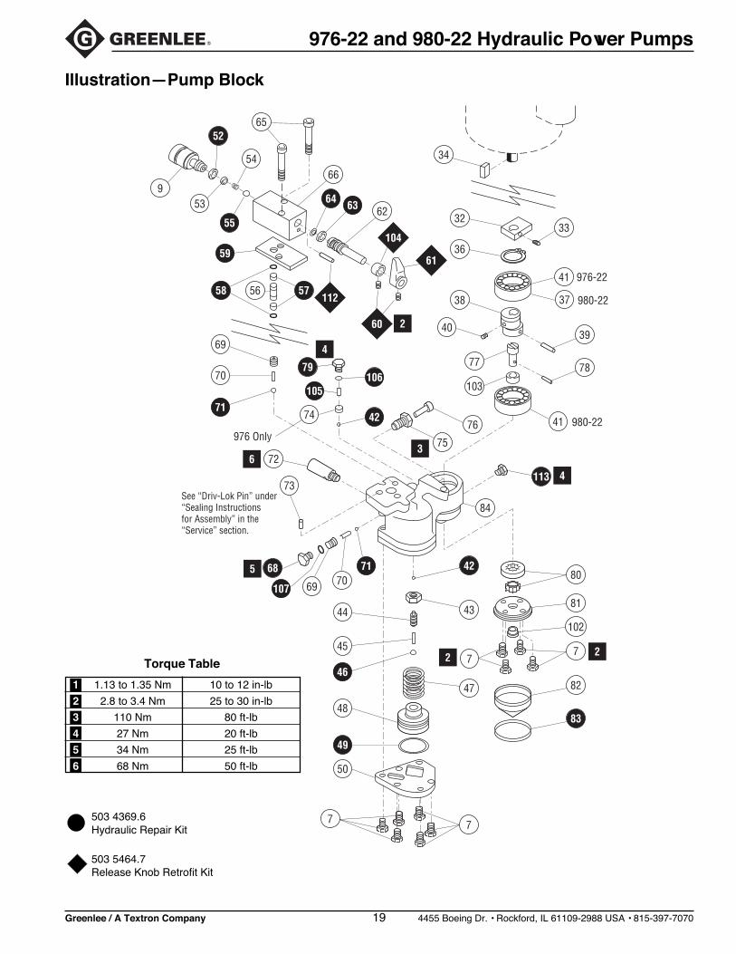
Illustration—Pump Block
78
77
50
49
48
46
45
44
47
7
43
42717069107
68
73
72
71
70
69
105
79106
42
58 56 57
104
61
60
112
55
52
64 63
59
66
65
34
32
36
33
41
38
3940
77
103
41 980-22
980-22
976-22
76
75
84
80
81
102
82
83
7
37
113
62
54
539
22
5
63
4
4
2
74
976 Only
See “Driv-Lok Pin” under“Sealing Instructionsfor Assembly” in the“Service” section.
1 1.13 to 1.35 Nm 10 to 12 in-lb
2 2.8 to 3.4 Nm 25 to 30 in-lb
3 110 Nm 80 ft-lb
4 27 Nm 20 ft-lb
5 34 Nm 25 ft-lb
6 68 Nm 50 ft-lb
503 4369.6Hydraulic Repair Kit
503 5464.7Release Knob Retrofit Kit
Torque Table

Greenlee / A Textron Company 20 4455 Boeing Dr. • Rockford, IL 61109-2988 USA • 815-397-7070
976-22 and 980-22 Hydraulic Power Pumps
Key Part No. Description Qty
Parts List
1 50335189 Carrying handle ................................................................................. 22 90537092 1/4–20 x 1-1/4" Hex head screw ....................................................... 8
3 50344323 Decal, identification (976-22) ............................................................. 150363077 Decal, identification and specification (980-22) ................................. 1
4 91863538 Motor, 220 VAC, 1/2 hp (976-22) ...................................................... 1
91864445 Motor, 220 VAC, 1-1/2 hp (980-22) ................................................... 1GE Motor 5KC49TG20T Stk #739FE Motor 1103017407
6 50326619 Fill-Vent plug ..................................................................................... 1
7 90505204 1/4–20 x 3/4" Hex head screw ........................................................ 148 50343963 Motor control unit (includes items 91–101) ....................................... 19 90508076 Coupling ............................................................................................ 1
10 50334883 Shroud ............................................................................................... 111 50334905 Reservoir (976-22) ............................................................................ 1
50335555 Reservoir (980-22) ............................................................................ 1
12 50335359 Short retaining strap .......................................................................... 213 50335367 Long retaining strap........................................................................... 214 50335375 Release valve unit (includes items 52–66) ........................................ 1
15 50343980 I.D. decal, specifications and warning (976-22) ................................ 150354914 I.D. decal, warning (980-22) .............................................................. 1
16 50158325 Arrow decal ....................................................................................... 1
17 Eccentric unit (refer to “Illustration—Pump Block”) ........................... 118 Pump block unit (refer to “Illustration—Pump Block”) ....................... 119 90505301 Hex head cap screw, 3/8–16 x 1.00" ................................................. 3
*21 90536827 Seal ................................................................................................... 122 50335170 Cover plate ........................................................................................ 1
*23 50326279 Cover plate gasket ............................................................................ 1
24 90538293 Rubber foot ........................................................................................ 425 90511859 Screw, 1/4–20 x 1/2" ......................................................................... 426 90514602 Self-tapping screw 10 x 3/8" .............................................................. 2
27 90534689 #10 Flat washer ................................................................................. 228 90523393 1/4" Flat washer ................................................................................ 431 50398962 Mounting strap ................................................................................... 1
32 50335278 Counterweight ................................................................................... 133 90512693 Set screw, 1/4–20 x 1/4" ................................................................... 134 50145576 Motor shaft key, 3/16" x 1-3/8" .......................................................... 1
35 90505336 Hex head cap screw 3/8–16 x 1.50" .................................................. 136 90537076 Retaining ring .................................................................................... 137 90537580 Ball bearing #1206 ............................................................................ 1
38 50335260 Eccentric shaft ................................................................................... 139 90506995 Rollpin, 3/16" x 1" .............................................................................. 140 90507916 Set screw, 10–32 x 1/4" .................................................................... 1
SERVICE PARTS: GE FE
Greenlee No. 91864992 52020801
Capacitor Manufacturing No. 275464116
Greenlee No. 91863791 52020802
Cover, Cap Manufacturing No. 111B276AA1 276856101

Greenlee / A Textron Company 21 4455 Boeing Dr. • Rockford, IL 61109-2988 USA • 815-397-7070
976-22 and 980-22 Hydraulic Power Pumps
Key Part No. Description Qty
Parts List (cont’d)
41 90537041 Ball bearing, #3206 ........................................................................... 1*42 90506782 Ball, 3/16" .......................................................................................... 2
43 90500164 Jam nut, 1/2–20................................................................................. 144 50335200 Stem .................................................................................................. 145 50225345 Spring ................................................................................................ 1
*46 90506790 Ball, 1/4" ............................................................................................ 147 90537017 Spring ................................................................................................ 148 50335197 Auto valve piston ............................................................................... 1
*49 90503406 O-ring, 1-5/8" x 2" x 3/16" .................................................................. 150 50335219 Pump block cover .............................................................................. 1
*52 90535030 Retaining ring .................................................................................... 1
53 90534689 Plain flat type “A” washer .................................................................. 154 90535103 Compression spring .......................................................................... 1
*55 90506804 Ball, 5/16" .......................................................................................... 1
56 50326228 Coupling ............................................................................................ 1*57 90512901 Backup ring, 3/8" x 1/2" x 1/16" ......................................................... 2*58 90501683 O-ring, 3/8" x 1/2" x 1/16" .................................................................. 2
*59 50326260 Gasket ............................................................................................... 1+60 90512693 Set screw, 1/4–20 x .38" ................................................................... 2+61 50347969 Release valve knob ........................................................................... 1
62 50335413 Control shaft ...................................................................................... 1*63 90538277 Backup ring, 1/2" x 5/8" x 1/16" ......................................................... 1*64 90509129 O-ring, 1/2" x 5/8" x 1/16" .................................................................. 1
65 90534964 Cap screw, 5/16–18 x 2.50" .............................................................. 266 50326236 Release valve body ........................................................................... 1
*68 90536983 O-ring plug (includes item 107) ......................................................... 1
69 90537122 Jam screw, 7/16" ............................................................................... 270 90537025 Spring ................................................................................................ 2
*71 90504364 Ball, 9/32" .......................................................................................... 2
72 50060678 High-pressure relief valve .................................................................. 173 90537068 Pin, type “D” Driv-Lok 1/4" x 1/2" ....................................................... 174 50343106 Insert, cavity (976-22 Only) ............................................................... 1
75 50335316 High-pressure bushing (976-22) ........................................................ 150335308 High-pressure bushing (980-22) ........................................................ 1
76 50335324 High-pressure piston (976-22) ........................................................... 1
50335286 High-pressure piston (980-22) ........................................................... 177 50335251 Drive shaft ......................................................................................... 178 50329340 Drive pin ............................................................................................ 1
*79 90536991 O-ring plug (includes item 106) ......................................................... 180 90535170 Gerotor .............................................................................................. 181 50341979 Lower gerotor plate unit (includes item 102) ..................................... 1
82 50335243 Filter .................................................................................................. 1*83 90537661 O-ring, 2-3/8" x 2-5/8" x 1/8" ............................................................. 184 50335332 Pump block........................................................................................ 1
85 50323709 Faceplate decal ................................................................................. 186 91862655 Switch ................................................................................................ 187 50319027 Handle, right half ............................................................................... 1
88 90534417 Self-tapping screw, 6–20 x 5/8" ......................................................... 389 50319019 Handle, left half ................................................................................. 190 50323628 Cord................................................................................................... 1
Greenlee / A Textron Company 22 4455 Boeing Dr. • Rockford, IL 61109-2988 USA • 815-397-7070
976-22 and 980-22 Hydraulic Power Pumps
Key Part No. Description Qty
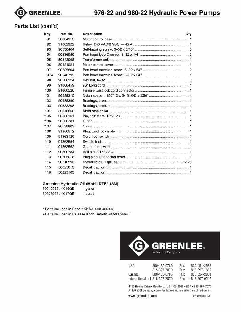
Parts List (cont’d)
91 50334913 Motor control base............................................................................. 1
92 91862922 Relay, 240 VAC/8 VDC — 45 A ........................................................ 193 90538404 Self-tapping screw, 6–32 x 5/16" ....................................................... 694 90536959 Pan head type C screw, 6–32 x 1/4" ................................................. 2
95 50343998 Transformer unit ................................................................................ 196 50334921 Motor control cover ............................................................................ 197 90535804 Pan head machine screw, 6–32 x 5/8" .............................................. 2
97A 90548795 Pan head machine screw, 6–32 x 3/8" .............................................. 198 90506324 Hex nut, 6–32 .................................................................................... 399 91868459 96" Long cord .................................................................................... 1
100 91860520 Female twist lock cord connector ...................................................... 1101 90538315 Nylon spacer, .150" ID x 5/16" OD x .050" ........................................ 4102 90538390 Bearings, bronze ............................................................................... 1
103 90533208 Bearings, bronze ............................................................................... 1+104 50348868 Shaft stop collar ................................................................................. 1*105 90538161 Pin, 1/8" x 1/4" Driv-Lok .................................................................... 1
*106 90538781 O-ring ................................................................................................ 1*107 90538803 O-ring ................................................................................................ 1108 91860512 Plug, twist lock male .......................................................................... 1
109 91863120 Cord, foot switch................................................................................ 1110 91863554 Switch, foot ........................................................................................ 1111 91863562 Guard, foot switch ............................................................................. 1
+112 90500784 Roll pin, 3/16" x 3/4" .......................................................................... 1113 90505018 Plug pipe 1/8" socket head ................................................................ 1114 90510593 Hydraulic oil, 1 gal, ea. ................................................................. 2.25
115 50025813 Decal, caution .................................................................................... 1116 50225103 Decal, caution .................................................................................... 1
Greenlee Hydraulic Oil (Mobil DTE® 13M)90510593 / 4016GB 1 gallon90508068 / 4017GB 1 quart
* Parts included in Repair Kit No. 503 4369.6+Parts included in Release Knob Retrofit Kit 503 5464.7
USA 800-435-0786 Fax: 800-451-2632 815-397-7070 Fax: 815-397-1865Canada 800-435-0786 Fax: 800-524-2853International +1-815-397-7070 Fax: +1-815-397-9247
4455 Boeing Drive • Rockford, IL 61109-2988 • USA • 815-397-7070An ISO 9001 Company • Greenlee Textron Inc. is a subsidiary of Textron Inc.
www.greenlee.com Printed in USA