96 Guides - ERIC - Education Resources Information Center · · 2014-05-14Definitions. The terms...
40
ED 401 424 TITLE INSTITUTION SPONS AGENCY REPORT NO PUB DATE CONTRACT NOTE AVAILABLE FROM PUB TYPE EDRS PRICE DESCRIPTORS ABSTRACT DOCUMENT RESUME CE 072 916 Specification for Qualification and Certification for Level II Advanced Welders. American Welding Society, Miami, FL. Department of Education, Washington, DC. AWS-QC11-96 96 V244B30006-95 55p.; For the final program report, see CE 072 915. For related specifications and guides, see CE 072 917-919 and ED 398 388-389. American Welding Society, 550 N.W. LeJeune Road, Miami, FL 33126; phone: 800-334-WELD. Legal/Legislative/Regulatory Materials (090) Guides Non-Classroom Use (055) MF01/PC03 Plus Postage. *Certification; *Employment Qualifications; Evaluation Criteria; *Minimum Competency Testing; Performance Tests; Postsecondary Education; Records (Forms); *Specifications; *Trade and Industrial Education; *Welding This document defines the requirements and program for the American Welding Society (AWS) to certify advanced-level welders through an evaluation process entailing performance qualification and practical knowledge tests requiring the use of advanced reading, computational, and manual skills. The following items are included: statement of the standard's scope; definitions of key terms; requirements for participating organizations; - _- purposes/scope of the written examinations and performance tests; inspection, testing, and acceptance criteria; documentation requirement; certification procedure; and information about the National Registry of Level II-Advanced Welders. Appended are the following: workmanship qualification test report; face- and root-bend test report; optional AWS certification tests; and welding procedure specifications. Twelve figures/tables are included. (MN) *********************************************************************** Reproductions supplied by EDRS are the best that can be made from the original document. ***********************************************************************
Transcript of 96 Guides - ERIC - Education Resources Information Center · · 2014-05-14Definitions. The terms...

ED 401 424
TITLE
INSTITUTIONSPONS AGENCYREPORT NOPUB DATECONTRACTNOTE
AVAILABLE FROM
PUB TYPE
EDRS PRICEDESCRIPTORS
ABSTRACT
DOCUMENT RESUME
CE 072 916
Specification for Qualification and Certification forLevel II Advanced Welders.American Welding Society, Miami, FL.Department of Education, Washington, DC.AWS-QC11-9696
V244B30006-9555p.; For the final program report, see CE 072 915.For related specifications and guides, see CE 072917-919 and ED 398 388-389.American Welding Society, 550 N.W. LeJeune Road,Miami, FL 33126; phone: 800-334-WELD.Legal/Legislative/Regulatory Materials (090)Guides Non-Classroom Use (055)
MF01/PC03 Plus Postage.*Certification; *Employment Qualifications;Evaluation Criteria; *Minimum Competency Testing;Performance Tests; Postsecondary Education; Records(Forms); *Specifications; *Trade and IndustrialEducation; *Welding
This document defines the requirements and programfor the American Welding Society (AWS) to certify advanced-levelwelders through an evaluation process entailing performancequalification and practical knowledge tests requiring the use ofadvanced reading, computational, and manual skills. The followingitems are included: statement of the standard's scope; definitions ofkey terms; requirements for participating organizations; -
_-
purposes/scope of the written examinations and performance tests;inspection, testing, and acceptance criteria; documentationrequirement; certification procedure; and information about theNational Registry of Level II-Advanced Welders. Appended are thefollowing: workmanship qualification test report; face- and root-bendtest report; optional AWS certification tests; and welding procedurespecifications. Twelve figures/tables are included. (MN)
***********************************************************************
Reproductions supplied by EDRS are the best that can be madefrom the original document.
***********************************************************************

A
I
III
AS
AI
I
I
AO.
.
. o
. o
A a A
U Sr DEPARTMENT OF EDUCATIONOffice Educational Research and Improvement
ED ATIONAL RESOURCES INFORMATIONCENTER (ERIC)
This document has been reproduced as,...-, received from the person or organization
Originating itCr Minor changes have been made to improve
reproduction quality
Points°l view or opinions stated in this documeat do not necessarily represent officialOERI positron or policy
0
BEST COPY AVAILABLE
2
I I I
:
a .

Key words advanced level welder, participatingorganization, performance tests,acceptance criteria, National Registry
AWS QC 1 1 -96
Specification for Qualification and
Certification for Level II - Advanced Welders
Funded by theU.S. Department of Education
Grant V244B30006-95
Prepared by theAWS Education and Certification Departments
Under the Direction of theAWS Education Grant Committee
Approved by theAWS Board of Directors
Abstract
This standard defines the requirements and program for the American Welding Society to certify advanced level welders.The certification of Level II - Advanced Welders requires performance qualification and practical knowledge tests. Thesetests require more detailed skills of reading, computational, and manual skills to complete.
American Welding Society
550 N.W. LeJeune Road, Miami, Florida 33126

Statement on Use of AWS Standards
All standards (codes, specifications, recommended practices, methods, classifications, and guides) of the AmericanWelding Society are voluntary consensus standards that have been developed in accordance with the rules of theAmerican National Standards Institute. When AWS standards are either incorporated in, or made part of,documents that are included in federal or state laws and regulations, or the regulations of other governmentalbodies, their provisions carry the full legal authority of the statute. In such cases, any changes in those AWSstandards must be approved by the governmental body having statutory jurisdiction before they can become a partof those laws and regulations. In all cases, these standards carry the full legal authority of the contract or otherdocument that invokes the AWS standards. Where this contractual relationship exists, changes in or deviationsfrom requirements of an AWS standard must be by agreement between the contracting parties.
International Standard Book Number: 0-87171-473-6
American Welding Society, 550 N.W. LeJeune Road, Miami, Florida 33126
© 1996 by American Welding Society.All rights reserved
Printed in the United States of America
Note: The primary purpose of AWS is to serve and benefit its members. To this end, AWS provides a forumfor the exchange, consideration, and discussion of ideas and proposals that are relevant to the welding industryand the consensus of which forms the basis for these standards. By providing such a forum, AWS does notassume any duties to which a user of these standards may be required to adhere. By publishing this standard,the American Welding Society does not insure anyone using the information it contains against any liabilityarising from that use. Publication of a standard by the American Welding Society does not carry with it any rightto make, use, or sell any patented items. Users of the information in this standard should make an independent,substantiating investigation of the validity of that information for their particular use and the patent status of anyitem referred to herein.
With regard to technical inquiries made concerning AWS standards, oral opinions on AWS standards may berendered. However, such opinions represent only the personal opinions of the particular individuals giving them.These individuals do not speak on behalf of AWS, nor do these oral opinions constitute official or unofficialopinions or interpretations of AWS. In addition, oral opinions are informal and should not be used as a substitutefor an official interpretation.
This standard is subject to revision at any time by the AWS Certification Committee. Comments(recommendations, additions, or deletions) and any pertinent data that may be of use in improving this standardare requested and should be addressed to AWS Headquarters. Such comments will receive careful considerationby the AWS Certification Committee and the author of the comments will be informed of the Committee'sresponse to the comments. Guests are invited to attend all meetings of the AWS Certification Committee toexpress their comments verbally. Procedures for appeal of an adverse decision concerning all such commentsare provided in the Rules of Operation of the Technical Activities Committee. A copy of these Rules can beobtained from the American Welding Society, 550 N.W. LeJeune Road, Miami, Florida 33126.
4

Personnel
AWS Education Grant Committee
F.G. Delaurier, ChairmanN.C. Wall, Vice ChairmanR. V. Reeve, Co-SecretaryJ.R. Hufsey, Co-Secretary
R.L. O'Brien, Program ManagerJ Bartley
S.W. BollingerF. Cusma
J.E. GreerS.C. Helzer, Advisor
J. HoeftD.G. Howden
J.H. IvyL.G. Kvidahl
R. MurrayL.W. Myers
A.L. PetroskiR.C. Pierce
S.L. RaymondR.J. Teuscher, Ex-OfficioE.R. Bohnart, Ex-OfficioC.E. Pepper, Ex-Officio
American Welding SocietyAmerican Welding SocietyAmerican Welding SocietyAmerican Welding SocietyAmerican Welding SocietyConsulting EngineerThe Esab Group, Inc.Pacific Northwest IronworkersStandard Refrigeration/AutoradUniversity of Northern IowaMiller Electric Mfg. CompanyThe Ohio State UniversityIngalls ShipbuildingIngalls ShipbuildingH & M Steel, Inc.Dresser-Rand, Inc.Valmet, Inc. Honeycomb DivisionWelding Engineering Supply Co.National Training FundIndustrial Gas ProductsMiller Electric Mfg. CompanyLockwood Greene Engineers

Foreword
(This Foreword is not a part of AWS QC11-96, Specification for Qualification and Certification of Level II -Advanced Welders, but is included for information purposes only).
This standard extends the work of the American Welding Society to further define a national skill standard forthe Level II - Advanced Welder. The American Welding Society was awarded Grant #V244B30006-95 for$1,059,626 by the U.S. Department of Education to develop standards and a certification program for weldersduring the period from July 1993 to July 1996. The total program cost is $2,132,094, of which 49.7%($1,072,468) is an in-kind contribution by AWS.
To accomplish its goals, AWS organized an Education Grant Committee, which has representatives from allsegments of the welding industry, including labor organizations and educational institutions. This Committee hasoverseen the efforts toward a standard for the qualification and certification of the Level II - Advanced Welder.
The development of this National Skill Standard has involved the participation of the welding industry througha survey designed to determine a consensus of welder skills and competencies required for individuals seekingto continue the development of their welding skills.
The results of this industry survey were an occupational task analysis that formed the basis for curriculumguidelines to guide the training of the Level II - Advanced Welder candidate.
This standard defines the requirements for the certification of such individuals and their entry into the NationalRegistry of Level II - Advanced Welders.
Comments and suggestions for improvement of this standard are welcome. They should be sent in writing tothe Secretary, AWS Certification Committee, American Welding Society, 550 N.W. LeJeune Road, Miami,Florida 33126.
6-iv-

Table of Contents
Page No.
Personnel iiiForeword ivList of Tables viList of Figures vi
1. Scope 1
2. Definitions 1
3. Requirements for Participating Organizations 2
4. Written Examinations 3
5. Performance Tests 3
6. Inspection, Testing, and Acceptance Criteria 4
7. Documentation 5
8. Certification 5
9. National Registry of Level II - Advanced Welders 5
Annex A - Workmanship Qualification Test Report 8
Annex B - Face- and Root-Bend Test Report 9
Annex C - Optional AWS QC7 Certification Tests 10
Annex D - Welding Procedure Specifications 20
-v-
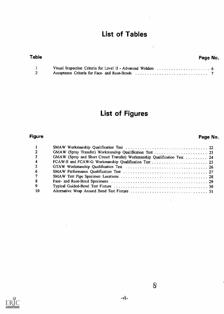
List of Tables
Table Page No.
1 Visual Inspection Criteria for Level II - Advanced Welders 62 Acceptance Criteria for Face- and Root-Bends 7
List of Figures
Figure Page No.
1 SMAW Workmanship Qualification Test 222 GMAW (Spray Transfer) Workmanship Qualification Test 233 GMAW (Spray and Short Circuit Transfer) Workmanship Qualification Test 244 FCAW-S and FCAW-G Workmanship Qualification Test 255 GTAW Workmanship Qualification Test 266 SMAW Performance Qualification Test 277 SMAW Test Pipe Specimen Locations 288 Face- and Root-Bend Specimens 299 Typical Guided-Bend Test Fixture 3010 Alternative Wrap Around Bend Test Fixture 31

Specification for Qualification and Certificationfor Level II Advanced Welders
1. Scope
1.1 This standard establishes the minimum requirements for an organization to participatewith the American Welding Society (AWS) in the qualification and certification ofadvanced welders.
1.2 This standard specifies practical knowledge and performance tests that require a moredetailed level of reading, computational, and manual skills to successfully complete.
1.3 All individuals that meet the specified performance at a facility meeting 3.Requirements for Participating Organizations will be listed in The National Registry ofLevel II - Advanced Welders at the American Welding Society.
1.4 Organizations not meeting 3. Requirements for Participating Organizations mayuse this standard, but individuals they certify will not be listed in the National Registry ofLevel II - Advanced Welders.
1.5 Although a written test including questions on safety is required by this standard, thisstandard is not intended to address safety and health. Safety and health requirements areprovided in ANSI Z49.1, Safety in Welding and Cutting, other safety and health standards,and federal, state, and local government regulations. The responsibility for safety of theLevel II - Advanced Welder is primarily with the welder, the Participating Organizationduring training and testing, and afterwards, with the employer.
1.6 The requirements of this standard shall not supersede the authority of the trainingfacility as established by the local evaluation guidelines.
2. Definitions
The terms used in this standard are defined in ANSI/AWS A3.0, Standard Welding Termsand Definitions. Other terms are defined as follows:
1) Participating Organization - Any organization meeting 3. Requirements forParticipating Organizations.
2) Level II - Advanced Welder - An individual employed in this position isconsidered to possess a prerequisite amount of knowledge, attitude, skills, andhabits required to perform proceduralized tasks under general supervision, andcomplex tasks involving the use of theoretical knowledge and motor skills underclose supervision.

3. Requirements for Participating Organizations
3.1 Participating Organizations may be training-and-testing or testing-only facilities.
3.2 Participating Organizations shall maintain and follow a quality manual that assurescompliance with this specification.
3.3 An application for registration as a Participating Organization shall be submitted witha cover letter signed by the Senior Official at the Facility. The cover letter shall certify toAWS that the Facility has a Quality Program which will be rigorously followed, and thatthe requirements of this standard will be met.
3.3.1 If the Participating Organization is a training-and-testing organization, theletter shall also state that their curriculum follows AWS EG3.0, Guide for Trainingand Qualification of Welding Personnel - Level II - Advanced Welders.
3.3.2 Participating Organizations already registered for the Entry Level Weldertraining program must notify AWS of their intention to administer the Level II -Advanced Welder curriculum.
3.4 Test supervisors for testing-and-training or testing-only Participating Organizationsshould be AWS Certified Welding Inspectors.
3.5 Instructors for testing-and-training Participating Organizations should be AWSCertified Welding Educators.
3.6 Quality System Audits. Audits may be required if evidence of nonconformance withthe Participating Organization's Quality Program or this specification exists.
3.6.1 Allegations of nonconformance supported by documentary evidence will bepresented to the AWS Certification Committee. The Committee may require:
1) A written statement by the Senior Official of the Participating Organization withsupporting evidence refuting the allegations, and a statement by the SeniorOfficial of the Participating Organization that the requirements of theParticipating Organization Quality Program and this Specification have been metin the past, and will be met in the future, or
2) An on-site quality audit by an AWS Approved Assessor to verify that therequirements of the Quality Program and this Specification have been and arebeing met.
3.6.2 If a quality audit is required by the Committee, then the ParticipatingOrganization has two options, as follows:
-2- 10
1) The Participating Organization may decline to be audited and resign from theProgram, or
2) The Participating Organization may agree to be audited, in which case the SeniorOfficial of the Participating Organization shall issue a purchase order to AWS foradministrative fees and expenses of the assessor.
4. Written Examinations
4.1 The written examinations are designed to show that the Level II - Advanced Welderunderstands the following subjects:
MathematicsEmployability SkillsSafe PracticesWelding Terms and DefinitionsLayout/Fitup Principles and PracticesCodes/StandardsQualification and CertificationWelding SpecificationsWelding TheoryWeldabilityWelding Inspection and TestingCutting TheoryCutting Terms and Definitions
4.2 A minimum passing grade of 75% is required with at least 90% of the safetyquestions answered correctly, with no limits on retests. Individuals failing one part of thewritten examination must retest on all parts of the examination.
5. Performance Tests
Performance tests are designed to show that the Level II - Advanced Welder can:
1) Pass workmanship qualification tests using SMAW, using stainless steel fillermetal on carbon or stainless steel.
2) Pass a performance qualification test using SMAW on carbon steel pipe in the6G position.
3) Pass workmanship qualification tests using GMAW in spray transfer mode onaluminum, all positions.
4) Pass a combination pipe and plate workmanship qualification test using GMAWon carbon steel, in short circuit and spray transfer modes, in positions 2F, 5G,and 5F.
5) Pass a combination pipe and plate workmanship qualification test using self- andgas-shielded FCAW on carbon steel in the 5G - 5F positions.
-3-

6) Pass a combination round tubing and sheet workmanship qualification test usingGTAW on carbon steel, aluminum, and stainless steel in the 5F - 5G positions.
7) Demonstrate satisfactory performance using OFC and CAC-A in carbon steel,and PAC in carbon steel, aluminum and stainless steel.
5.1. The Level II - Advanced Welder shall prepare, by mechanical, oxyfuel gas, or plasmaarc cutting, the parts as designated in Figures 1 through 5.
5.2. The Level II - Advanced Welder shall assemble the parts prepared in 5.1, as shown inFigures 1 through 5.
5.3 The Level II - Advanced Welder shall weld the assemblies using the WPS indicatedon the drawing for each assembly. The WPSs specified are listed in Annex D.
5.4 As an option, the Level II - Advanced Welder may perform the performancequalification tests as detailed in Annex C in accordance with Supplement G of AWS QC7,Standard for AWS Certified Welders. The purpose of AWS QC7 is to document the abilityof welders to deposit sound welds (qualify) and to impose controls on the documentationand maintenance of certification (certify). Welder performance qualification testsadministered within the AWS QC7 program are conducted at AWS Accredited TestFacilities. Such facilities operate under the requirements of AWS QC4, Standard forAccreditation of Test Facilities for AWS Certified Welder Program.
5.5 Participating Organizations may elect to substitute any of the performancequalifications listed in Annex C for the workmanship or performance qualificationrequirements detailed in Figures 1 through 5. Substituted performance qualifications shallcover all aspects of the replaced workmanship or performance qualification test, withrespect to welding process, welding positions, base metal, filler metal and product form.
6. Inspection, Testing, and Acceptance Criteria
6.1 All cut edges shall be visually examined and the cut surfaces shall meet the criteria ofAWS C4.1 Sample 2 with grinding. After inspection, the cut surfaces may be conditionedto bright metal.
6.2 All assemblies shall be visually examined and the welds shall meet the acceptancecriteria shown in Table 1.
6.3 Butt joints welded with the shielded metal arc welding process in the 6G positionshall be cut to produce face- and root-bend specimens as shown in Figure 7.
6.4 Face- and root-bend specimens shall be conditioned as shown in Figure 8, and bent ina bend fixture similar to Figure 9 or 10, in accordance with ANSI/AWS B4.0, StandardMethods for Mechanical Testing of Welds.
-4- 12

6.5 Face- and root-bend specimens after bending shall meet the requirements ofTable 2.
7. Documentation
For each successful Level II - Advanced Welder, the Participating Organization shallprepare a report containing the following:
1) The Level II - Advanced Welder's name and Social Security Number,
2) The actual grade on the written examinations,
3) The actual grade on the Safety portion of the written examination,
4) The results of the visual inspection of each workmanship qualification test, and
5) The results of the SMAW 6G performance qualification test.
8. Certification
8.1 The Participating Organization shall send the report to the American Welding Society.
8.2 The American Welding Society shall enter the data into the Level II - AdvancedWelder database.
9. National Registry of Level II - Advanced Welders
The Level II - Advanced Welder database shall function as the National Registry of LevelII - Advanced Welders.
9.1 Persons listed in the databank are not required to maintain registration by reportingwelding activities.
9.2 Public disclosure of individual records in the National Registry of Level II -Advanced Welders shall be at the discretion of the individual welders.
-5-13

Table 1
Visual Inspection Criteria for Level II - Advanced Welders
1) There shall be no cracks or incomplete fusion.
2) There shall be no incomplete joint penetration in groove welds except aspermitted for partial joint penetration groove welds.
3) The Test Supervisor shall examine the weld for acceptable appearance, and shallbe satisfied that the welder is skilled in using the process and procedure specifiedfor the test.
4) Undercut shall not exceed the lesser of 10% of the base metal thickness or 1/32in. (0.8 mm).
5) Where visual examination is the only criterion for acceptance, all weld passes aresubject to visual examination, at the discretion of the Test Supervisor.
6) The frequency of porosity shall not exceed one in each 4 in. (100 mm) of weldlength and the maximum diameter shall not exceed 3/32 in. (2.4 mm).
7) Welds shall be free from overlap.
-6-14

Table 2
Acceptance Criteria for Face- and Root-Bends
For acceptance, the convex surface of the face- and root-bend specimens shall meet both ofthe following requirements:
1. No single indication shall exceed 1/8" (3.2 mm), measured in any direction onthe surface.
2. The sum of the greatest dimensions of all indications on the surface, whichexceed 1/32" (0.8 mm), but are less than or equal to 1/8" (3.2 mm), shall notexceed 3/8" (9.6 mm).
Cracks occurring at the corner of the specimens shall not be considered unless there isdefinite evidence that they result from slag inclusions or other internal discontinuities.
-7- 15

Annex A
Workmanship Qualification Test Report
Visual Inspection
Name of Student:Social Security No.:Sample #
Size:
Under OK
Undercut:
Acceptable Rejected
Porosity:
Diameter of Largest
Acceptable Rejected
Overlap:
Acceptable Rejected
Penetration:
Acceptable Rejected
Appearance:
Acceptable Rejected
Cracks:
Acceptable Rejected
Excessive
Name: Date:(Please Print)
Signature:
16-8-

Annex B
Face- and Root-Bend Test Report
Name of Student:
Social Security No.:
6G Face-bend:
Length of each discontinuity (Over 1/32") Sum
Accept Reject
6G Root-bend:
Length of each discontinuity (Over 1/32") Sum
Accept Reject
Name: Date:(Please Print)
Signature:
-9- 17

See
Det
ails
'A' I
. Ban
d N
ote
7
See
Not
es 2
& 3
4**4
.=1
/\ PIP
E IN
CLI
NA
TIO
N F
IXE
D (
45*
IT )
AN
D N
OT
RO
TA
TE
D D
UR
ING
WE
LDIN
G
TE
ST
PO
SIT
ION
6G
a =
60°
min
imum
R =
5/3
7, :1
/16'
f = 1
/16
min
imum
DE
TA
IL 'A
" -
Join
t Geo
met
ry W
ithou
t Bac
king
INC
HM
M
1/16
1.6
1/8
3.2
1/4
6.4
1/2
12.7
125
.4
a =
60°
min
imum
R =
3/1
6% +
1/4*
-1/
6f =
R/2
max
imum
DE
TA
IL r
- J
oint
Geo
met
ry W
ith B
acki
ng
Not
es:
1. A
dmin
istr
atio
n of
this
per
form
ance
qua
lific
atio
n te
stin
acc
orda
nce
with
AW
S Q
C7,
Sup
plem
ent G
, sup
erse
des
AW
S Q
C11
and
AW
S E
G3.
0 re
quire
men
ts o
f Per
form
ance
Qua
lific
atio
n fo
r S
MA
W o
f car
bon
stee
l pip
e.2.
6' o
r 8"
0 S
ched
ule
80 c
arbo
n st
eel p
ipe
(M-1
/P-1
/S
-1, G
roup
1 o
r 2)
.3.
The
sta
ndar
d pi
pe g
roov
e te
st w
eldm
ent f
or p
erfo
rman
cequ
alifi
catio
n sh
all c
onsi
st o
f tw
o pi
pe s
ectio
ns, e
ach
am
inim
um o
f 3 in
. (76
mm
) lo
ng jo
ined
by
wel
ding
to m
ake
one
test
wel
dmen
t a m
inim
um o
f 6 in
. (15
0 m
m)
long
.4.
With
or
with
out b
acki
ng.
Bac
king
rin
g to
sui
t dia
met
eran
d no
min
al w
all t
hick
ness
of p
ipe.
Ref
er to
Det
ails
"A
'an
d B
.5.
All
wel
ding
don
e in
pos
ition
acc
ordi
ng to
app
licab
le
perf
orm
ance
qua
lific
atio
n re
quire
men
ts.
6. A
ll pa
rts
may
be
mec
hani
cally
cut
or
mac
hine
OF
C.
7. U
se W
PS
AN
SI/A
WS
B2.
1-1-
022
for
perf
orm
ance
qual
ifica
tion
with
out b
acki
ng.
Use
WP
S A
NS
I/AW
S B
2.1-
1-01
6 fo
r pe
rfor
man
ce
qual
ifica
tion
with
bac
king
.8.
Vis
ual e
xam
inat
ion
in a
ccor
danc
e w
ith th
e re
quire
men
tsof
AW
S B
2.1,
sec
tions
3.5
.1 a
nd 3
.5.3
.1.
Ben
d te
st In
acc
orda
nce
with
the
requ
irem
ents
of
AW
S B
2.1,
sec
tions
3.5
.3.1
, 3.7
.1.2
and
Fig
ure
3.7.
1B.
Perf
orm
ance
Qua
lific
atio
n T
est -
SM
AW
, Car
bon
Stee
l, 6G
Pos
ition
1819

TE
ST
PO
SIT
ION
3G
(V
ertic
al U
p)(P
late
s V
ertic
al; A
xis
of W
eld
Ver
tical
)
1-1/
2' w
idth
Fac
eB
end
Spe
cim
en
3/8
11
TE
ST
PO
SIT
ION
4G
(O
verh
ead)
(Pla
tes
Hor
izon
tal)
1-1/
2' w
idth
Roo
t - B
end
Spe
cim
en
a
INC
HM
M
1/16
1.6
1/8
3.2
1/4
6.4
1/2
12.7
125
.4
See
Not
e 5
and
Det
ail '
A'
It
a =
60°
flat
pos
ition
90°
horiz
onta
l or
vert
ical
pos
ition
110°
ove
rhea
d po
sitio
n
R =
3/3
2% +
1/13
-1/
16
=1/
16' m
inim
um
Det
ail "
A"
- Jo
int G
eom
etry
With
Bac
king
20
6 M
IN
7 M
IN
Not
es:
1. A
dmin
istr
atio
n of
this
per
form
ance
qua
lific
atio
n te
stin
acc
orda
nce
with
AW
S 0
07, S
uppl
emen
t G, s
uper
sede
sA
WS
OC
11 a
nd A
WS
EG
3.0
requ
irem
ents
of W
orkm
an-
ship
Qua
lific
atio
n fo
r G
MA
W (
spra
y tr
ansf
er)
of a
lum
inum
2. 3
/8' t
hick
ness
alu
min
um (
M-2
3/P
-23/
S-2
3 or
(M
-22/
P-2
2/S
-22
to M
-22/
P-2
2/S
-22)
, as
deta
iled
in A
WS
B2.
1.3.
Per
form
ance
Qua
lific
atio
n #1
= 3
G p
ositi
on.
Per
form
ance
Qua
lific
atio
n #2
= 4
G p
ositi
on.
4. A
ll w
eldi
ng d
one
in p
ositi
on a
ccor
ding
toap
plic
able
per
form
ance
qua
lific
atio
n re
quire
men
t.5.
With
bac
king
. Bac
king
mat
eria
l 1/4
' x 3
' x 7
" m
inim
um(M
-23/
P-2
3/S
-23
to M
-23/
P-2
3/S
-23)
or
(M-2
2/P
-22/
S-2
2 to
M-2
2/P
-22/
S-2
2), a
s sp
ecifi
ed in
AW
S B
2.1.
6. A
ll pa
rts
may
be
mec
hani
cally
cut
or
mac
hine
PA
C.
7. U
se W
PS
AW
S2-
1-G
MA
W fo
r (M
-23/
P-2
3/S
-23)
.U
se W
PS
AW
S2-
1.1-
GM
AW
for
(M-2
2/P
-22/
S-2
2).
8. V
isua
l exa
min
atio
n in
acc
orda
nce
with
the
requ
irem
ents
of A
WS
B2.
1, s
ectio
ns 3
.5.1
and
3.5
.3.1
.B
end
test
in a
ccor
danc
e w
ith th
e re
quire
men
ts o
fA
WS
B2.
1, s
ectio
ns 3
.5.3
.1, 3
.7.2
.1 a
nd F
igur
e 3.
7.2A
.
Perf
orm
ance
Qua
lific
atio
n T
est -
GM
AW
Sho
rt C
ircu
it, C
arbo
n St
eel,
3G -
4G
Pos
ition
21

3/8'
wid
thS
ide
Ben
d S
peci
men
TE
ST
PO
SIT
ION
1G
(fla
t)
(Pla
tes
Hor
izon
tal)
3/8'
wid
thS
ide
- B
end
Spe
cim
en
a
INC
HM
M
1/16
1.6
1/8
3.2
1/4
6.4
1/2
12.7
125
.4
See
Not
e
and
Det
ail '
A'
6 M
IN
a =
45"
min
imum
R =
NC
, 1/4
' -1/
16'
I = R
i2 m
ay
Det
ail "
A"
- Jo
int G
eom
etry
With
Bac
king
7 M
IN
Not
es:
1. A
dmin
istr
atio
n of
this
per
form
ance
qua
lific
atio
n te
stin
acc
orda
nce
with
AW
S 0
07, S
uppl
emen
t G, s
uper
sede
sA
WS
I3C
11 a
nd A
WS
EG
3.0
requ
irem
ents
of W
orkm
an-
ship
Qua
lific
atio
n fo
r G
MA
W (
spra
y tr
ansf
er)
of c
arbo
nst
eel p
ipe.
2. 1
' thi
ckne
ss c
arbo
n st
eel (
M-1
/P-1
/S-1
, gro
up 1
or
2),
as d
etai
led
in A
WS
B2.
1.3.
Per
form
ance
Qua
lific
atio
n #1
= 1
G p
ositi
on.
4. A
ll w
eldi
ng d
one
in p
ositi
on a
ccor
ding
to a
pplic
able
perf
orm
ance
qua
lific
atio
n re
quire
men
t.5.
With
bac
king
. Bac
king
mat
eria
l 114
' xx
7' m
inim
um(M
-1/P
-1/S
-1, G
roup
1 o
r 2)
as
spec
ified
in A
WS
B2.
1.6.
All
part
s m
ay b
e m
echa
nica
lly c
ut o
r m
achi
ne O
FC
.
7. U
se W
PS
AW
S2-
3-G
MA
W.
8. V
isua
l exa
min
atio
n in
acc
orda
nce
with
the
requ
irem
ents
of A
WS
B2.
1, s
ectio
ns 3
.5.1
and
3.5
.3.1
.B
end
test
as
deta
iled
and
in a
ccor
danc
e w
ith th
ere
quire
men
ts o
f AW
S B
2.1,
sec
tions
3.5
.3.1
, 3.7
.2.1
and
Fig
ure
3.7.
2A.
22Pe
rfor
man
ce Q
ualif
icat
ion
Tes
t - G
MA
WSp
ray
Tra
nsfe
r, C
arbo
n St
eel,
1G P
ositi
on
23

PIP
E O
R T
UB
E V
ER
TIC
AL
AN
DN
OT
RO
TA
TE
D D
UR
ING
WE
LDIN
G.
WE
LD H
OR
IZO
NT
AL
0151
.
INC
HM
M
1/16
1.6
1/8
3.2
1/4
6.4
1/2
12.7
125
.4
PIP
E H
OR
IZO
NT
AL
FIX
ED
( :1
5) A
ND
NO
T R
OT
AT
ED
DU
RIN
G W
ELD
ING
. WE
LD F
LAT
, VE
RT
ICA
L, O
VE
RH
EA
D.
15'
15*
TE
ST
PO
SIT
ION
2G
(H
OR
IZO
NT
AL)
TE
ST
PO
SIT
ION
5G
(M
ULT
IPLE
)
1314
fifT
a =
60°
min
imum
R =
311
6', +
1/4'
-1/
16'
f = R
/2 m
axim
um
(A)
Join
t Det
ail -
with
bac
king
Not
es:
1. A
dmin
istr
atio
n of
this
per
form
ance
qua
lific
atio
n te
stin
acc
orda
nce
with
AW
S 0
07, S
uppl
emen
t G, s
uper
sede
sA
WS
QC
11 a
nd A
WS
EG
3.0
requ
irem
ents
of W
orkm
an-
ship
Qua
lific
atio
n fo
r F
CA
W-S
(se
lf-sh
ield
ed)
of c
arbo
nst
eel p
ipe.
2. 6
' or
W 0
Sch
edul
e 80
car
bon
stee
l pip
e (M
-1/P
-1/
S-1
, Gro
up 1
or
2).
3. T
he s
tand
ard
pipe
gro
ove
test
wei
dmen
ts fo
r pe
rfor
man
cequ
alifi
catio
n sh
all c
onsi
st o
f tw
o pi
pe s
ectio
ns, e
ach
am
inim
um o
f 3 in
. (76
mm
) lo
ng jo
ined
by
wel
ding
to m
ake
one
test
wel
dmen
t a m
inim
um o
f 6 in
. (15
0 m
m)
long
.4.
Per
form
ance
Qua
lific
atio
n #1
= 2
G p
ositi
on.
Per
form
ance
Qua
lific
atio
n #2
= 5
G p
ositi
on.
5. A
ll w
eldi
ng d
one
in p
ositi
on a
ccor
ding
toap
plic
able
per
form
ance
qua
lific
atio
n re
quire
men
t.
6. W
ith b
acki
ng.
Bac
king
rin
g to
sui
t dia
met
eran
d no
min
al w
all t
hick
ness
of p
ipe.
Ref
er to
Det
ail '
A°.
7. A
ll pa
rts
may
be
mec
hani
cally
cut
or
mac
hine
OF
C.
8. U
se W
PS
AN
SI/A
WS
B2.
1-1-
027.
9. V
isua
l exa
min
atio
n in
acc
orda
nce
with
the
requ
irem
ents
of A
WS
B2.
1, s
ectio
ns 3
:5.1
and
3.5
.3.1
.B
end
test
in a
ccor
danc
e w
ith th
e re
quire
men
ts o
fA
WS
62.
1, s
ectio
ns 3
.5.3
.1, 3
.7.1
.2 a
nd F
igur
e 3.
7.10
.
24Pe
rfor
man
ce Q
ualif
icat
ion
Tes
t - F
CA
W-S
, Car
bon
Stee
l,2G
- 5
G P
ositi
on25

26
15 1
15'
TE
ST
PO
SIT
ION
2G
(H
OR
IZO
NT
AL)
TE
ST
PO
SIT
ION
5G
(M
ULT
IPLE
)
PIP
E O
R T
UB
E V
ER
TIC
AL
AN
DN
OT
RO
TA
TE
D D
UR
ING
WE
LDIN
G.
WE
LD H
OR
IZO
NT
AL
( :1
5).
INC
HM
M
1/16
1.6
1/8
3.2
1/4
6.4
112
12.7
125
.4
PIP
E H
OR
IZO
NT
AL
FIX
ED
(±
15')
AN
D N
OT
RO
TA
TE
D
DU
RIN
G W
ELD
ING
. WE
LD F
LAT
, VE
RT
ICA
L O
VE
RH
EA
D.
a =
60°
min
imum
R =
311
6% +
1/4'
-1/
16'
f = R
/2 m
axim
um
(A)
Join
t Det
ail -
with
bac
king
Not
es:
1. A
dmin
istr
atio
n of
this
per
form
ance
qua
lific
atio
n te
stin
acc
orda
nce
with
AW
S 0
07, S
uppl
emen
t G, s
uper
sede
sA
WS
0C
11 a
nd A
WS
EG
3.0
requ
irem
ents
of W
orkm
an-
ship
Qua
lific
atio
n fo
r F
CA
W-S
(ga
s-sh
ield
ed)
of c
arbo
n
stee
l pip
e.2.
6' o
r 8'
0 S
ched
ule
80 c
arbo
n st
eel p
ipe
(M-1
/P-1
/S-1
,G
roup
1 o
r 2)
.3.
The
sta
ndar
d pi
pe g
roov
e te
st w
eldm
ents
for
perf
orm
ance
qual
ifica
tion
shal
l con
sist
of t
wo
pipe
sec
tions
, eac
h a
min
imum
of 3
in. (
76 m
m)
long
join
ed b
y w
eldi
ng to
mak
eon
e te
st w
eidm
ent a
min
imum
of 6
in. (
150
mm
) lo
ng.
4. P
erfo
rman
ce Q
ualif
icat
ion
#1 =
2G
pos
ition
.P
erfo
rman
ce Q
ualif
icat
ion
#2 =
5G
pos
ition
.
5. A
ll w
eldi
ng d
one
in p
ositi
on a
ccor
ding
to a
pplic
able
perf
orm
ance
qua
lific
atio
n re
quire
men
t.6.
With
bac
king
.B
acki
ng r
ing
to s
uit d
iam
eter
and
nom
inal
wal
l thi
ckne
ss o
f pip
e. R
efer
to D
etai
l 'A
'.
7. A
ll pa
rts
may
be
mec
hani
cally
cut
or
mac
hine
OF
C.
8. U
se W
PS
AN
SI/A
WS
B2.
1-1-
019
or A
NS
I/AW
S 8
2.1-
1-02
0.9.
Vis
ual e
xam
inat
ion
in a
ccor
danc
e w
ith th
e re
quire
men
tsof
AW
S B
2.1,
sec
tions
3.5
.1 a
nd 3
.5.3
.1.
Ben
d te
st in
acc
orda
nce
with
the
requ
irem
ents
of
AW
S B
2.1,
sec
tions
3.5
.3.1
, 3.7
.1.2
and
Fig
ure
3.7.
1C.
Perf
orm
ance
Qua
lific
atio
n T
est -
FC
AW
-G,
Car
bon
Stee
l,2G
- 5
G P
ositi
on
BE
ST C
OPY
AV
AIL
AB
LE
27

C4
PIP
E O
R T
UB
E V
ER
TIC
AL
AN
D
NO
T R
OT
AT
ED
DU
RIN
G W
ELD
ING
.W
ELD
HO
RIZ
ON
TA
L 41
51.
IT IT
TE
ST
PO
SIT
ION
2G
(H
OR
IZO
NT
AL)
a =
60°
, 1.1
0° -
5°
R =
5/3
2", :
1/16
"f =
1/16
min
imum
INC
HM
M
1/16
1.6
1/8
3.2
1/4
6.4
1/2
12.7
125
.4
PIP
E H
OR
IZO
NT
AL
FIX
ED
( :1
5) A
ND
NO
T R
OT
AT
ED
DU
RIN
G W
ELD
ING
. WE
LD F
LAT
, VE
RT
ICA
L, O
VE
RH
EA
D.
TE
ST
PO
SIT
ION
5G
(M
ULT
IPLE
)
a =
60°
, 4.1
0° -
5°R
= 5
/32'
,11/
16'
f =1/
16 m
inim
um
DE
TA
IL 'A
" -
Join
t Geo
met
ry W
ithou
t Bac
king
DE
TA
IL'S
' - J
oint
Geo
met
ry W
ith B
acki
ng
Not
es:
1. A
dmin
istr
atio
n of
this
per
form
ance
qua
lific
atio
n te
stin
acc
orda
nce
with
AW
S 0
07, S
uppl
emen
t G, s
uper
sede
sA
WS
0C
11 a
nd A
WS
EG
3.0
requ
irem
ents
of W
orkm
an-
ship
Qua
lific
atio
n fo
r G
MA
W (
shor
t circ
uit t
rans
fer)
of
carb
on s
teel
pip
e.2.
4' o
r 6'
0 S
ched
ule
40 c
arbo
n st
eel p
ipe
(M-1
/P-1
/S
-1, G
roup
1 o
r 2)
.3.
The
sta
ndar
d pi
pe g
roov
e te
st w
eldm
ents
for
perf
orm
ance
qual
ifica
tion
shal
l con
sist
of t
wo
pipe
sec
tions
, eac
h a
min
imum
of 3
in. (
76 m
m)
long
join
ed b
y w
eldi
ng to
mak
eon
e te
st w
eldm
ent a
min
imum
of 6
in. (
150
mm
) lo
ng.
4. P
erfo
rman
ce Q
ualif
icat
ion
#1 =
2G
pos
ition
.P
erfo
rman
ce Q
ualif
icat
ion
#2 =
5G
pos
ition
.5.
All
wel
ding
don
e in
pos
ition
acc
ordi
ng to
appl
icab
le p
erfo
rman
ce q
ualif
icat
ion
requ
irem
ent.
6. W
ith o
r w
ithou
t bac
king
.B
acki
ng r
ing
to s
uit d
iam
eter
and
nom
inal
wal
l thi
ckne
ss o
f pip
e. R
efer
to D
etai
ls A
.an
d T
.7.
All
part
s m
ay b
e m
echa
nica
lly c
ut o
r m
achi
ne O
FC
.8.
Use
WP
S A
WS
2-2-
GM
AW
.9.
Vis
ual e
xam
inat
ion
in a
ccor
danc
e w
ith th
e re
quire
men
tsof
AW
S B
2.1,
sec
tions
3.5
.1 a
nd 3
.5.3
.1.
Ben
d te
st in
acc
orda
nce
with
the
requ
irem
ents
of
AW
S B
2.1,
sec
tions
3.5
.3.1
, 3.7
.1.2
and
Fig
ure
3.7.
1C.
Perf
orm
ance
Qua
lific
atio
n T
est -
GM
AW
-S, C
arbo
n St
eel,
2G -
5G
Pos
ition
29
1

RO
UN
D T
UB
ING
VE
RT
ICA
L A
ND
NO
T R
OT
AT
ED
DU
RIN
G W
ELD
ING
.
WE
LD H
OR
IZO
NT
AL
(t15
).
15' 1
5
TE
ST
PO
SIT
ION
2G
(H
OR
IZO
NT
AL)
R =
Ti (
max
imum
)T
= 1
0 ga
. thr
ough
18
ga.
(A)
Join
t Det
ail -
with
out b
acki
ng
INC
HM
M
1/16
1.6
1/8
3.2
1/4
6.4
1/2
12.7
125
.4
RO
UN
D T
UB
ING
HO
RIZ
ON
TA
L F
IXE
D 0
15')
AN
D N
OT
RO
TA
TE
D
DU
RIN
G W
ELD
ING
. WE
LD F
LAT
, VE
RT
ICA
L, O
VE
RH
EA
D.
TE
ST
PO
SIT
ION
5G
(M
ULT
IPLE
)
R =
Ti (
max
imum
)T
i = T
2T
= 1
0 ga
. thr
ough
18
ga.
(B)
Join
t Det
ail -
with
bac
king
Not
es:
1.A
dmin
istr
atio
n of
this
per
form
ance
qua
lific
atio
n te
stin
acc
orda
nce
with
AW
S 0
07, S
uppl
emen
t G, s
uper
sede
sA
WS
0C
11 a
nd A
WS
EG
3.0
requ
irem
ents
of W
orkm
an-
ship
Qua
lific
atio
n fo
r G
TA
W o
f car
bon
stee
l rou
nd tu
bing
.
2.2-
7/8"
0, 1
0 ga
. - 1
8 ga
. car
bon
stee
l rou
nd tu
bing
.O
ptio
nal c
hoic
e of
dia
met
er a
nd w
all t
hick
ness
with
in
rang
e sp
ecifi
ed.
3.T
he s
tand
ard
roun
d tu
bing
gro
ove
test
wel
dmen
ts fo
rpe
rfor
man
ce q
ualif
icat
ion
shal
l con
sist
of t
wo
roun
d tu
b-in
g se
ctio
ns, e
ach
a m
inim
um o
f 3 In
. (76
mm
) lo
ngjo
ined
by
wel
ding
to m
ake
one
test
wel
dmen
t a m
inim
umof
6 In
. (15
0 m
m)
tong
.4.
Per
form
ance
Qua
lific
atio
n /1
= 2
G p
ositi
on.
Per
form
ance
Qua
lific
atio
n 12
= 5
G p
ositi
on.
5.A
ll w
eldi
ng d
one
in p
ositi
on a
ccor
ding
to a
pplic
able
perf
orm
ance
qua
lific
atio
n re
quire
men
t.6.
With
or
with
out b
acki
ng.
Bac
king
rin
g to
sui
t dia
met
eran
d no
min
al w
all t
hick
ness
of p
ipe.
Ref
er to
Det
ails
'A'
and
Ir.
7.R
oot s
hiel
ding
gas
opt
iona
l.8.
All
part
s m
ay b
e m
echa
nica
lly c
ut o
r m
achi
ne O
FC
.
9. U
se W
PS
AN
SI/A
WS
B2.
1.00
8.10
. Vis
ual e
xam
inat
ion
in a
ccor
danc
e w
ith th
e re
quire
men
tsof
AW
S B
2.1,
sec
tions
3.5
.1 a
nd 3
.5.3
.1. B
end
test
Inac
cord
ance
with
the
requ
irem
ents
of A
WS
B2.
1, s
ectio
ns3.
5.3.
1, 3
.7.1
.2 a
nd F
igur
e 3.
7.1C
. Ben
d sp
ecim
ens
=1/
2' (
13 m
m)
wid
e x
6 in
(15
0 m
m)
long
.
Perf
orm
ance
Qua
lific
atio
n T
est -
GT
AW
, Car
bon
Stee
l,2G
- 5
G P
ositi
on
303

RO
UN
D T
UB
ING
VE
RT
ICA
L A
ND
NO
T R
OT
AT
ED
DU
RIN
G W
ELD
ING
.
WE
LD H
OR
IZO
NT
AL
(I15
' ).
15 1
T
TE
ST
PO
SIT
ION
2G
(H
OR
IZO
NT
AL)
R =
Ti (
max
imum
)
T =
10 g
a. th
roug
h 18
ga.
(A)
Join
t Det
ail -
with
out b
acki
ng
32
)
INC
HM
M
1/16
1.6
1/8
3.2
1/4
6.4
1/2
12.7
125
.4
RO
UN
D T
UB
ING
HO
RIZ
ON
TA
L F
IXE
D (
t15)
AN
D N
OT
RO
TA
TE
DD
UR
ING
WE
LDIN
G. W
ELD
FLA
T, V
ER
TIC
AL,
OV
ER
HE
AD
.
TE
ST
PO
SIT
ION
5G
(M
ULT
IPLE
)
R =
Ti (
max
imum
)T
t = T
2
T =
10
ga. t
hrou
gh 1
8 ga
.
(B)
Join
t Det
ail -
with
bac
king
Not
es:
1A
dmin
istr
atio
n of
this
per
form
ance
qua
lific
atio
n te
stIn
acc
orda
nce
with
AW
S Q
C7,
Sup
plem
ent G
, supe
rsed
esA
WS
QC
11 a
nd A
WS
EG
3.0
requ
irem
ents
of W
orkm
an-
ship
Qua
lific
atio
n fo
r G
TA
W o
f alu
min
um r
ound
tubi
ng.
2.1"
2-7/
8' 0
, 10
ga. -
18
ga. a
lum
inum
rou
nd tu
bing
(M-2
2/P
-22/
S-2
2 to
M-2
2/P
-22/
S-2
2) o
r (M
-23/
P-2
3/S
-23
to M
-23/
P-2
3/S
-23)
. Opt
iona
l cho
ice
of d
iam
eter
,w
all t
hick
ness
and
mat
eria
l with
inra
nge
spec
ified
.3.
The
sta
ndar
d ro
und
tubi
ng g
roov
e te
st w
eldm
ents
for
perf
orm
ance
qua
lific
atio
n sh
all c
onsi
st o
f tw
o ro
und
tub-
ing
sect
ions
, eac
h a
min
imum
of 3
in. (
76 m
m)
long
join
ed b
y w
eldi
ng to
mak
e on
e te
st w
eldm
ent a
min
imum
of 6
in. (
150
mm
) lo
ng.
4.P
erfo
rman
ce Q
ualif
icat
ion
#1 =
2G
pos
ition
.P
erfo
rman
ce Q
ualif
icat
ion
#2 =
5G
pos
ition
.5.
All
wel
ding
don
e in
pos
ition
acc
ordi
ng to
app
licab
lepe
rfor
man
ce q
ualif
icat
ion
requ
irem
ent.
6.W
ith o
r w
ithou
t bac
king
.B
acki
ng r
ing
to s
uit d
iam
eter
and
nom
inal
wal
l thi
ckne
ss o
f pip
e. R
efer
to D
etai
ls 'A
"an
d 'B
'.7.
Roo
t shi
eldi
ng g
as r
equi
red.
8.A
ll pa
rts
may
be
mec
hani
cally
cut
or
mac
hine
PA
C.
9.U
se W
PS
AW
S 2
-1-G
TA
W fo
r M
-23/
P-2
3/S
-23.
Use
WP
S A
WS
2-1
.1-G
TA
W fo
r M
-22/
P-2
2/S
-22.
10. V
isua
l exa
min
atio
n in
acc
orda
nce
with
the
requ
irem
ents
of A
WS
B2.
1, s
ectio
ns 3
.5.1
and
3.5
.3.1
.B
end
test
in a
ccor
danc
e w
ith th
e re
quire
men
ts o
f
AW
S B
2.1,
sec
tions
3.5
.3.1
, 3.7
.1.2
and
Fig
ure
3.7.
1C.
Ben
d sp
ecim
ens
=1/
2' (
13 m
m)
wid
e x
6 in
(15
0m
m)
long
.
Perf
orm
ance
Qua
lific
atio
n T
est -
GT
AW
, Alu
min
um,
2G -
5G
Pos
ition
33

00
1571
;
TE
ST
PO
SIT
ION
2G
(H
OR
IZO
NT
AL)
RO
UN
D T
UB
ING
VE
RT
ICA
L A
ND
NO
T R
OT
AT
ED
DU
RIN
G W
ELD
ING
.W
ELD
HO
RIZ
ON
TA
L (±
15').
R =
Ti (
max
imum
)T
= 1
0 ga
. thr
ough
18
ga.
(A)
Join
t Det
ail -
with
out b
acki
ng
INC
HM
M
1/16
1.6
1/8
3.2
1/4
6.4
1/2
12.7
125
.4
RO
UN
D T
UB
ING
HO
RIZ
ON
TA
L F
IXE
D (
±15
') A
ND
NO
T R
OT
AT
ED
DU
RIN
G W
ELD
ING
. WE
LD F
LAT
, VE
RT
ICA
L, O
VE
RH
EA
D.
TE
ST
PO
SIT
ION
50
(MU
LTIP
LE)
R =
Ti (
max
imum
)T
i = T
2T
=10
ga.
thro
ugh
18 g
a.
(B)
Join
t Det
ail -
with
bac
king
Not
es:
1.A
dmin
istr
atio
n of
this
per
form
ance
qua
lific
atio
n te
stIn
acc
orda
nce
with
AW
S Q
C7,
Sup
plem
ent G
, sup
erse
des
AW
S O
C11
and
AW
S E
G3.
0 re
quire
men
ts o
f Wor
kman
-sh
ip Q
ualif
icat
ion
for
GT
AW
of s
tain
less
ste
el r
ound
tubi
ng.
2.1'
2-71
8- 0
, 10
ga. -
18
ga. s
tain
less
ste
el r
ound
tubi
ng.
Opt
iona
l cho
ice
of d
iam
eter
and
wal
l thi
ckne
ss w
ithin
rang
e sp
ecifi
ed.
3.T
he s
tand
ard
roun
d tu
bing
gro
ove
test
wel
dmen
ts fo
rpe
rfor
man
ce q
ualif
icat
ion
shal
l con
sist
of t
wo
roun
d tu
b-in
g se
ctio
ns, e
ach
a m
inim
um o
f 3 In
. (76
mm
) lo
ngjo
ined
by
wel
ding
to m
ake
one
test
wel
dmen
t a m
inim
um
of 6
in. (
150
mm
) lo
ng.
4.P
erfo
rman
ce Q
ualif
icat
ion
#1 =
2G
pos
ition
.P
erfo
rman
ce Q
ualif
icat
ion
#2 =
5G
pos
ition
.5.
All
wel
ding
don
e in
pos
ition
acc
ordi
ng to
app
licab
le
perf
orm
ance
qua
lific
atio
n re
quire
men
t.6.
With
or
with
out b
acki
ng.
Bac
king
rin
g to
sui
t dia
met
eran
d no
min
al w
all t
hick
ness
of p
ipe.
Ref
er to
Det
ails
'A'
and
B.
7.R
oot s
hiel
ding
gas
req
uire
d.8.
All
part
s m
ay b
e m
echa
nica
lly c
ut o
r m
achi
ne O
FC
.9.
Use
WP
S A
NS
I/AW
S 8
2.1.
009.
10. V
isua
l exa
min
atio
n in
acc
orda
nce
with
the
requ
irem
ents
of A
WS
B2.
1, s
ectio
ns 3
.5.1
and
3.5
.3.1
.B
end
test
in a
ccor
danc
e w
ith th
e re
quire
men
ts o
fA
WS
B2.
1, s
ectio
ns 3
.5.3
.1, 3
.7.1
.2 a
nd R
gure
3.7
.1C
.B
end
spec
imen
s =
1/2
' (13
mm
) w
ide
x 6
In (
150
mm
) lo
ng.
Perf
orm
ance
Qua
lific
atio
n T
est -
GT
AW
, Sta
inle
ss S
teel
,2G
- 5
G P
ositi
on
34.3
.5

TE
ST
PO
SIT
ION
3G
(V
ertic
al U
p)
(Pla
tes
Ver
tical
; Axi
s of
Wel
d V
ertic
al)
1-1/
2" w
idth
Fac
eB
end
Spe
cim
en
3/8
1 1/
TE
ST
PO
SIT
ION
4G
(O
verh
ead)
(Pla
tes
Hor
izon
tal)
1-1/
2' w
idth
Roo
t - B
end
Spe
cim
en
a
INC
HM
M
1/16
1.6
1/8
3.2
1/4
6.4
1/2
12.7
125
.4
See
Not
e 5
and
Det
ail '
A'
a =
45°
R =
1/4
', +
1/4
-1/1
6
I = F
t/2 m
axim
um
Det
ail "
A"
- Jo
int G
eom
etry
With
Bac
king
36
6 M
IN
7 M
IN
Not
es:
1. A
dmin
istr
atio
n of
this
per
form
ance
qua
lific
atio
n te
stin
acc
orda
nce
with
AW
S 0
07, S
uppl
emen
t G, s
uper
sede
sA
WS
OC
11 a
nd A
WS
EG
3.0
requ
irem
ents
of W
orkm
an-
ship
Qua
lific
atio
n fo
r S
MA
W o
f sta
inle
ss s
teel
.
2. 3
/13*
thic
knes
s au
sten
itic
stai
nles
s st
eel (
M-8
/P-8
/S-8
,G
roup
1),
as
deta
iled
in A
WS
B2.
1 an
d W
PS
AN
SI/A
WS
B2.
1-8-
023.
3. P
erfo
rman
ce Q
ualif
icat
ion
#1 =
3G
pos
ition
.P
erfo
rman
ce Q
ualif
icat
ion
#2 =
4G
pos
ition
.
4. A
ll w
eldi
ng d
one
in p
ositi
on a
ccor
ding
toap
plic
able
per
form
ance
qua
lific
atio
n re
quire
men
t.
5. W
ith b
acki
ng. B
acki
ng m
ater
ial 1
/4' x
3' x
T m
inim
um(M
8/P
-8/S
-8, G
roup
1)
as s
peci
fied
in A
WS
B2.
1.
6. A
ll pa
rts
may
be
mec
hani
cally
cut
or
mac
hine
PA
C.
7. U
se W
PS
AN
SI/A
WS
B2.
1-8-
023
8. V
isua
l exa
min
atio
n in
acc
orda
nce
with
the
requ
irem
ents
of A
WS
B2.
1, s
ectio
ns 3
.5.1
and
3.5
.3.1
.B
end
test
in a
ccor
danc
e w
ith th
e re
quire
men
ts o
fA
WS
B2.
1, s
ectio
ns 3
.5.3
.1, 3
.7.2
.1 a
nd F
igur
e 3.
7.2A
.
Perf
orm
ance
Qua
lific
atio
n T
est -
SM
AW
, Sta
inle
ss S
teel
,3G
- 4
G P
ositi
on
BE
ST C
OPY
AV
AIL
AB
LE
37

Annex D
Welding Procedure Specifications
ANSI/AWS B2.1 Standard for Welding Procedure and Performance QualificationANSI/AWS B2.1.008 Standard Welding Procedure Specification (WPS) for Gas Tungsten
Arc Welding of Carbon Steel (M-1, Group 1) 10 Gage through 18Gage, in the As-Welded Condition, With or Without Backing
ANSI/AWS B2.1.009 Standard Welding Procedure Specification (WPS) for Gas TungstenArc Welding of Austenitic Stainless Steel, (M-8/P-8), 10 Gagethrough 18 Gage, in the As-Welded Condition, With or WithoutBacking
ANSI/AWS B2.1-1-016 Standard Welding Procedure Specification (WPS) for Shielded MetalArc Welding of Carbon Steel (M-1/P-1/S-1, Group 1 or 2), 1/8through 1-1/2 inch Thick, E7018, As-Welded or PWHT Condition
ANSI/AWS B2.1.019 Standard Welding Procedure Specification (WPS) for CO2 ShieldedFlux Cored Arc Welding of Carbon Steel, (M-1/P-1/S-1, Group 1 or2), 1/8 through 1-1/2 inch Thick, E70T-1 and E71T-1, As-WeldedCondition
ANSI/AWS B2.1.020 Standard Welding Procedure Specification (WPS) for 75% Argon25% CO2 Shielded Flux Cored Arc Welding of Carbon Steel, (M-1/P-1/S-1, Group 1 or 2), 1/8 through 1-1/2 inch Thick, E70T-1 andE71T-1, As-Welded or PWHT Condition
ANSI/AWS B2.1-1-022 Standard Welding Procedure Specification (WPS) for Shielded MetalArc Welding of Carbon Steel, (M-1/P-1/S-1, Group 1 or 2), 1/8through 1-1/2 inch Thick, E6010, (Vertical Uphill) Followed byE7018, As-Welded or PWHT Condition
ANSI/AWS B2.1-8-023 Standard Welding Procedure Specification (WPS) for Shielded MetalArc Welding of Austenitic Stainless Steel, (M-8/P-8/S-8, Group 1 or2), 1/8 through 1-1/2 inch Thick, As-Welded Condition
ANSI/AWS B2.1-1-027 Standard Welding Procedure Specification (WPS) for Self-ShieldedFlux Cored Arc Welding of Carbon Steel, (M-8/P-8/S-8, Group 1 or2), 1/8 through 3/4 inch Thick, E71T-11, As-Welded Condition
AWS2-1-SMAW Welding Procedure Specification (WPS) for Shielded Metal ArcWelding of Austenitic Stainless Steel to Carbon Steel, (M-1 to M-8or P-8), 1/8 through 1/2 inch Thick, in the As-Welded Condition
AWS2-1-GMAW Welding Procedure Specification (WPS) for Gas Metal Arc Welding- Spray Transfer of Aluminum, (M-23/P-23/S-23), 1/8 through 3/4inch Thick, in the As-Welded Condition
AWS2-1.1-GMAW Welding Procedure Specification (WPS) for Gas Metal Arc Welding- Short Circuit Transfer of Aluminum, (M-22/P-22/S-22), 1/8through 3/4 inch Thick, in the As-Welded Condition
AWS2-2-GMAW Welding Procedure Specification (WPS) for Gas Metal Arc Welding- Short Circuit Transfer of Carbon Steel (M-1/P-1/S-1, Group 1 or2), 1/8 inch through 3/8 inch Thick, in the As-Welded Condition
-20-
38
Annex D
AWS2-3-GMAW Welding Procedure Specification (WPS) for Gas Metal Arc Welding- Spray Transfer of Carbon Steel (M-1/P-1/S-1, Group 1 or 2), 1/8inch through 3/8 inch Thick, in the As-Welded Condition
AWS2-1-GTAW Welding Procedure Specification (WPS) for Gas Tungsten ArcWelding of Aluminum, (M-23/P-23/S-23), 10 through 18 GaugeThick, in the As-Welded Condition
AWS2-1.1-GTAW Welding Procedure Specification (WPS) for Gas Tungsten ArcWelding of Aluminum, (M-22/P-22/S-22), 10 through 18 GaugeThick, in the As-Welded Condition
-2

See
Not
e 10
tJ 40
1/4rr
3/16
(3/
16)
60'
a:
0I- I- 50
'3/
16 (
3/16
)
0
See
Not
es 1
0 81
2
111
1/4
6'11
'3
13/1
6'
V
8'11
1111
/4rk
2-4T
--S
ee N
ote
8
Man
ual C
ut 0
1'S
ee N
ote
5
Man
ual C
ut T
his
Edg
eS
ee N
ote
5
1/2'
TY
P
1/4
2-4
INC
HM
M
1/16
1.6
1/8
3.2
1/4
6.4
1/2
12.7
125
.4
3/4'
TY
P
See
Not
es 1
0 8
133/
16 (
3/16
)50
'
NO
TE
S
1.A
ll di
men
sion
s U
.S. c
usto
mar
y un
less
oth
erw
ise
spec
ified
.2.
1/4'
thic
knes
s ca
rbon
ste
el m
ater
ial.
1/4'
thic
knes
s 3)
0( s
tain
less
ste
el m
ater
ial (
optio
nal).
3. T
he w
elde
r sh
all p
repa
re a
bill
of m
ater
ials
in U
.S.
cust
omar
y un
its o
f mea
sure
prio
r to
cut
ting.
4. T
he w
elde
r sh
all c
onve
rt th
e ab
ove
bill
of m
ater
ials
to S
.I. m
etric
uni
ts o
f mea
sure
.5.
All
carb
on s
teel
par
ts m
ay b
e m
echa
nica
lly c
ut o
rm
achi
ne O
FC
unl
ess
indi
cate
d 'M
anua
l Cur
then
use
man
ual O
FC
.
All
stai
nles
s st
eel p
arts
may
be
mec
hani
cally
cut
orm
achi
ne P
AC
unl
ess
indi
cate
d 'M
anua
l Cur
then
use
man
ual P
AC
.6.
Fill
er m
etal
s as
spe
cifie
d by
WP
S. (
See
Not
e 11
)7.
Fit
and
tack
ent
ire a
ssem
bly
on b
ench
bef
ore
atta
ch-
ing
to p
ositi
onin
g fix
ture
arm
.8.
Atta
ch 2
' x 2
' ext
ensi
on ta
b of
par
t 1 E
to p
ositi
onin
gfix
ture
arm
. ALL
WE
LDIN
G D
ON
E IN
PO
SIT
ION
AC
CO
RD
ING
TO
DR
AW
ING
OR
IEN
TA
TIO
N.
9.E
mpl
oy b
oxin
g te
chni
que
whe
re a
pplic
able
.10
. Par
tial p
enet
ratio
n w
eld.
11. U
se W
PS
AW
S2-
1-S
MA
W fo
r ca
rbon
ste
elba
se m
etal
.
Use
WP
S A
NS
I/AW
S 8
2.1-
8-02
3 fo
r st
ainl
ess
stee
lba
se m
etal
.
12. W
eld
join
s P
arts
1C
and
1D
to 1
E.
13. W
eld
join
s P
arts
1C
and
1E
to 1
A.
14. V
isua
l exa
min
atio
n in
acc
orda
nce
with
the
requ
irem
ents
of A
WS
QC
11, T
able
1.
Figu
re 1
- SM
AW
Wor
kman
ship
Qua
lific
atio
n T
est
41

See Det
ail
'A' a
ndN
ote
10
3/16
(3/
16)
See
Not
es 1
0 &
12
a:
3 13
/16'
42
3/16
(3/
16
INC
HM
M
1/16
1.6
1/8
3.2
1/4
6.4
1/2
12.7
125
.4
NO
TE
S45
' a r
- as
det
aile
d1.
All
dim
ensi
ons
U.S
. cus
tom
ary
unle
ss o
ther
wis
eR
0' to
3/3
2'f =
3/1
6'sp
ecifi
ed.
2.3/
8' th
ickn
ess
alum
inum
(M
-23/
P-2
3/S
-23
toM
-23/
P-2
3/S
-23)
or
(M-2
2/P
-221
S-2
2 to
M-2
2/P
-22/
S-2
2), a
s de
taile
d in
AW
S 8
2.1.
3. T
he w
elde
r sh
all p
repa
re a
bill
of m
ater
ials
in U
.S.
cust
omar
y un
its o
f mea
sure
prio
r to
cut
ting.
4. T
he w
elde
r sh
all c
onve
rt th
e ab
ove
bill
of m
ater
ials
to S
.I. m
etric
uni
ts o
f mea
sure
.
5.A
ll pa
rts
may
be
mec
hani
cally
cut
or
mac
hine
PA
Cun
less
indi
cate
d m
anua
l PA
C.
6.A
ll w
elds
GM
AW
, spr
ay tr
ansf
er.
7.F
it an
d ta
ck e
ntire
ass
embl
y on
ben
ch b
efor
e at
tach
-in
g to
pos
ition
ing
fixtu
re a
rm.
8.A
ttach
T x
T e
xten
sion
tab
of p
art 1
E to
pos
ition
ing
fixtu
re a
rm. A
LL W
ELD
ING
DO
NE
IN P
OS
ITIO
N
AC
CO
RD
ING
TO
DR
AW
ING
OR
IEN
TA
TIO
N.
9. E
mpl
oy b
oxin
g te
chni
que
whe
re a
pplic
able
.10
. Par
tial p
enet
ratio
n w
eld.
11. U
se W
PS
AW
S2-
1-G
MA
W fo
r (M
- 23
/P-
23/S
-23
).
Use
WP
S A
WS
2-1.
1-G
MA
W fo
r (M
-22/
P-2
2/S
-22)
.12
. Wel
d lo
ins
Par
ts 1
C a
nd 1
D to
1E
.
3/16
(3/
16)
13. W
eld
loin
s P
arts
1C
and
1E
to 1
A.
5514
. Vis
ual e
xam
inat
ion
in a
ccor
danc
e w
ith th
e
requ
irem
ents
of A
WS
OC
11, T
able
1.
-See
Not
e 8
Man
ual P
AC
01'
_LS
ee N
ote
5
Man
ual P
AC
Thi
s E
dge
See
Not
e 5
2-4
1/4
V 2
-4
1/T
TY
P
Det
ail '
A'
3/4'
TY
P
6'
See
Not
es 1
0 &
13
Figu
re 2
- G
MA
W (
Spra
y T
rans
fer)
Wor
kman
ship
Qua
lific
atio
n T
est
43

(1-;
See
Not
es28
7
3/16
p1 1
/2 -
3
3/16
1 1/
2 -
3
3/16
(3/
16)
N45
'S
ee N
otes
287 V
MA
W-S
0/4
L1 1
/2'--
11--
- 3'
See
Det
ail A
1/T
TY
P
1/2'
INC
HM
M
1/16
1.6
3.2
1/4
6.4
112
12.7
125
.4N
OT
ES
1.A
ll di
men
sion
s U
.S. c
usto
mar
y un
less
oth
erw
ise
spec
ified
.
See
Not
es2.
4' -
6' 0
Sch
edul
e 40
car
bon
stee
l pip
e.O
ptio
nal c
hoic
e of
pip
e di
amet
er w
ithin
ran
gesp
ecifi
ed.
3.1/
4' th
ickn
ess
carb
on s
teel
pla
te. U
seab
lepi
eces
may
be
join
ed to
obt
ain
desi
gn s
ize
Par
ts 1
A81
0. If
join
ed a
ll ad
ditio
nal w
elds
sha
ll be
gro
und
flush
prio
r to
ass
embl
y of
AW
S2-
3 w
eldm
ent.
4.U
se .0
35 d
iam
eter
E70
S-X
ele
ctro
de.
5. T
he w
elde
r sh
all p
repa
re a
bill
of m
ater
ials
in U
.S.
cust
omar
y un
its o
f mea
sure
prio
r to
cut
ting.
6.T
he w
elde
r sh
all c
onve
rt th
e ab
ove
bill
of m
ater
ials
to S
.I. m
etric
uni
ts o
f mea
sure
.7.
Par
ts 1
A,1
B 8
10
man
ual O
FC
. Sad
dle
Par
t 18
toac
com
mod
ate
Par
t 1C
.P
arts
1C
81E
may
be
mec
hani
cally
, mac
hine
OF
C, o
r m
anua
l OF
C c
ut.
8.A
ll w
elds
GM
AW
-S o
r G
MA
W (
spra
y) a
s sp
ecifi
ed.
9.F
it an
d ta
ck e
ntire
ass
embl
y on
ben
ch b
efor
e w
eldi
ng.
10. A
ttach
Par
t 1A
to w
eldi
ng ta
ble
or p
ositi
onin
g fix
ture
See
Not
esar
m. A
LL W
ELD
ING
DO
NE
IN P
OS
ITIO
N A
CC
OR
DIN
G
2 &
7I
TO
DR
AW
ING
OR
IEN
TA
TIO
N.
11. M
elt t
hrou
gh n
ot r
equi
red.
GM
AW
1/4
12. U
se W
PS
AW
S2-
2-G
MA
W fo
r sh
ort c
ircui
ting
tran
sfer
.U
se W
PS
AW
S2-
3-G
MA
W fo
r sp
ray
tran
sfer
.13
. Vis
ual e
xam
inat
ion
in a
ccor
danc
e w
ith th
ere
quire
men
ts o
f AW
S 0
C11
, Tab
le 1
.
3, 7
& 1
0
See
Not
es 3
8 7
Figu
re 3
- G
MA
W (
Spra
y an
d Sh
ort C
ircu
itT
rans
fer)
Wor
kman
ship
Qua
lific
atio
n T
est
4445
BE
ST C
OPY
AV
AIL
AB
LE
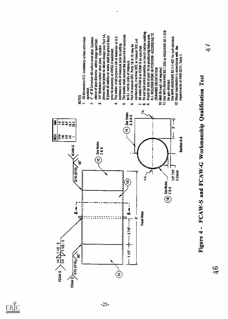
FC
AW
-S
FC
AW
-S
1/4
1 1/
2 -
3
1/4
1 1/
2 -
3
3/16
(3/
16)
A(3
/16)
60'
INC
HM
M
FC
AW
-G
0 S
ee N
otes
286
1/16
1.6
1/8
3.2
1/4
6.4
1/2
12.7
125
.4
1 1/
2'2
7/8'--
1A
9'
Fro
nt V
iew
See
Not
es
3, 6
8 9
1.5.
See
Not
es
286
n.s.
1/2'
TY
P
2 pl
aces
-- 3
.S
ectio
n A
-A
NO
TE
S
1.A
ll di
men
sion
s U
.S. c
usto
mar
y un
less
oth
erw
ise
spec
ified
.2.
4' -
0 S
ched
ule
40 c
arbo
n st
eel p
ipe.
Opt
iona
lch
oice
of p
ipe
diam
eter
with
in r
ange
spe
cifie
d.3.
1/4'
thic
knes
s ca
rbon
ste
el p
late
. Use
able
piec
es m
ay b
e jo
ined
to o
btai
n de
sign
siz
e P
art 1
A,
If jo
ined
all
addi
tiona
l wel
ds s
hall
be g
roun
d flu
shpr
ior
to a
ssem
bly
of A
WS
2-4
wei
dmen
t.4.
The
wel
der
shal
l pre
pare
a b
ill o
f mat
eria
ls in
U.S
.cu
stom
ary
units
of m
easu
re p
rior
to c
uttin
g.5.
The
wel
der
shal
l con
vert
the
abov
e bi
ll of
mat
eria
lsto
S.I.
met
ric u
nits
of m
easu
re.
6.P
art 1
A m
anua
l OF
C. P
arts
1B
& 1
C m
ay b
e
mec
hani
cally
, mac
hine
OF
C, o
r m
anua
l OF
C c
ut.
7.A
ll w
elds
FC
AW
-S o
r F
CA
W-G
as
spec
ified
.8.
Fit
and
tack
ent
ire a
ssem
bly
on b
ench
bef
ore
wel
ding
.9.
Atta
ch fa
r si
de o
f par
t 1A
to p
ositi
onin
g fix
ture
arm
.A
LL W
ELD
ING
DO
NE
IN P
OS
ITIO
N A
CC
OR
DIN
G T
OD
RA
WIN
G O
RIE
NT
AT
ION
.
10. M
elt t
hrou
gh n
ot r
equi
red.
11. U
se W
PS
AN
SI /
AW
S 8
2.1.
020
or A
NS
I/AW
S 8
2.1.
019
for
gas-
shie
lded
.U
se W
PS
AN
SI /
AW
S B
2.1-
1-02
7 fo
r se
lf-sh
ield
ed.
12. V
isua
l exa
min
atio
n in
acc
orda
nce
with
the
requ
irem
ents
of A
WS
0C
11, T
able
1.
Figu
re 4
- F
CA
W-S
and
FC
AW
-G W
orkm
ansh
ip Q
ualif
icat
ion
Tes
t
464

See
Not
es
8 th
roug
h 15
See
Not
es
8 th
roug
h 15
0 S
ee N
otes
1, 4
& 7
0 S
ee N
otes
1, 3
& 7
INC
HM
M
1/16
1.6
1/8
3.2
1/4
6.4
1/2
12.7
125
.4
1 1/
2*
48
1 1/
2*1/
2° T
YP
-t
NO
TE
S
1.1
each
req
uire
d, c
arbo
n st
eel,
alum
inum
and
sta
inle
ss s
teel
.2.
All
dim
ensi
ons
U.S
. cus
tom
ary
unle
ss o
ther
wis
e sp
ecifi
ed.
3.3'
0, 1
0 ga
.18
ga.
thic
knes
s ro
und
tubi
ng.
Opt
iona
l cho
ice
of w
all t
hick
ness
with
in r
ange
spe
cifie
d.4.
10 g
a. -
18
ga. m
ater
ial t
hick
ness
for
shee
t.O
ptio
nal c
hoic
e of
thic
knes
s w
ithin
ran
ge s
peci
fied.
5.T
he w
elde
r sh
all p
repa
re a
bill
of m
ater
ials
In U
.S.
cust
omar
y un
its o
f mea
sure
prio
r to
cut
ting.
6.T
he w
elde
r sh
all c
onve
rt th
e ab
ove
bill
of m
ater
ials
to S
.I.
met
ric u
nits
of m
easu
re.
7.P
art 1
A m
anua
l PA
C. P
art 1
B m
ay b
e m
echa
nica
lly o
r m
anua
lP
AC
cut
. Uni
form
ly r
adiu
s al
l sha
rp c
orne
rs.
8.A
ll W
elds
GT
AW
. Fill
et w
eld
size
= 1
1/2
tim
es th
e no
min
alw
all t
hick
ness
of t
he r
ound
tubi
ng. G
roov
e w
eld
root
ope
ning
=1/
2 th
e no
min
al w
all t
hick
ness
of t
he r
ound
tubi
ng.
9.G
roov
e w
eld
join
t geo
met
ry 1
6-18
gag
e us
e sq
uare
gro
ove.
Gro
ove
wel
d jo
int g
eom
etry
10-
14 g
age
use
v-gr
oove
.10
. No
mel
t thr
ough
on
fille
t wel
ds.
11. R
oot s
hiel
ding
gas
req
uire
d fo
r al
umin
um a
nd s
tain
less
ste
el.
12. F
it an
d ta
ck e
ntire
ass
embl
y on
ben
ch b
efor
e w
eldi
ng.
13. A
LL W
ELD
ING
DO
NE
IN P
OS
ITIO
N A
CC
OR
DIN
G T
O D
RA
WIN
G
OR
IEN
TA
TIO
N.
14. U
se W
PS
AN
SI/A
WS
82.
1.00
8 fo
r ca
rbon
ste
elU
se W
PS
AW
S2-
1-G
TA
W fo
r al
umin
um (
M-2
3/P
-23/
S-2
3).
Use
WP
S A
WS
2-1.
1-G
TA
W fo
r al
umin
um (
M-2
2/P
-22/
S-2
2).
Use
WP
S A
NS
I/AW
S 8
2.1.
009
for
stai
nles
s st
eel.
15. V
isua
l exa
min
atio
n in
acc
orda
nce
with
the
requ
irem
ents
of
AW
S O
C11
. Tab
le 1
.
Figu
re 5
- G
TA
W W
orkm
ansh
ip Q
ualif
icat
ion
Tes
t
49
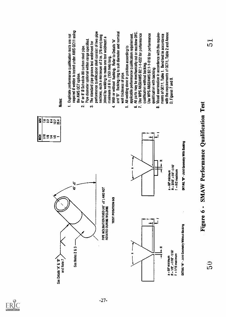
See
Det
ails
'A' 8
13*
and
Not
e 7
See
Not
es 2
8 3
45' :
5*
PIP
E IN
CLI
NA
TIO
N F
IXE
D (
45' I
T)
AN
D N
OT
RO
TA
TE
D D
UR
ING
WE
LDIN
G
TE
ST
PO
SIT
ION
6G
\---
a
riThf_17E1
JI.R
a =
60°
min
imum
R =
VT
, +1/
16-
-1/1
6'I =
1/1
6 m
axim
um
DE
TA
IL "
V -
Joi
nt G
eom
etry
With
out B
acki
ng
INC
HM
M
1/16
1.6
1/8
3.2
1/4
6.4
1/2
12.7
125
.4
a =
60°
min
imum
R =
3/1
6', +
VC
-1/
16'
f = R
/2 m
axim
um
DE
TA
IL -
11"
- Jo
int G
eom
etry
With
Bac
king
Not
es:
1. D
uplic
ate
perf
orm
ance
qua
lific
atio
n te
sts
are
not
requ
ired
if w
elde
r is
test
ed u
nder
AW
S 0
C11
usi
ngth
e A
WS
007
opt
ion.
2. 6
' or
8' 0
Sch
edul
e 80
car
bon
stee
l pip
e.P
ipe
diam
eter
opt
iona
l with
in r
ange
spe
cifie
d.3.
The
sta
ndar
d pi
pe g
roov
e te
st w
eldm
ent f
orpe
rfor
man
ce q
ualif
icat
ion
shal
l con
sist
of t
wo
pipe
sect
ions
, eac
h a
min
imum
of 3
in. (
76 m
m)
long
join
ed b
y w
eldi
ng to
mak
e on
e te
st w
eldm
ent a
min
imum
of 6
in. (
150
mm
) lo
ng.
4. W
ith o
r w
ithou
t bac
king
. Ref
er to
Det
ails
'A'
and
'V. B
acki
ng r
ing
to s
uit d
iam
eter
and
nom
inal
wal
l thi
ckne
ss o
f pip
e.5.
All
wel
ding
don
e in
pos
ition
acc
ordi
ng to
appl
icab
le p
erfo
rman
ce q
ualif
icat
ion
requ
irem
ent.
6. A
ll pa
rts
may
be
mec
hani
cally
cut
or
mac
hine
OF
C.
7. U
se W
PS
AN
SI/A
WS
B2.
1-1-
022
for
perf
orm
ance
qual
ifica
tion
with
out b
acki
ng.
Use
WP
S A
NS
I/AW
S B
2.1-
1-01
6 fo
r pe
rfor
man
cequ
alifi
catio
n w
ith b
acki
ng.
8. V
isua
l exa
min
atio
n in
acc
orda
nce
with
the
requ
ire-
men
ts o
f 0C
11, T
able
1. B
end
test
in a
ccor
danc
ew
ith th
e re
quire
men
ts o
f 0C
11, T
able
2 a
nd A
nnex
D, F
igur
es 7
and
8.
Figu
re 6
- S
MA
W P
erfo
rman
ce Q
ualif
icat
ion
Tes
t50
51

45.600 (typ)
Top of pipe5G or 6G
RootFace bendbend
Rootbend
Facebend
Figure 7 - SMAW Test Pipe Specimen Location
-28- 52

r--- 6 MIN (SEE NOTE 1)
II
NOTE 2 NOTE 3
Notes:1. A longer specimen length may be necessary.2. These edges may be oxygen-cut and may or may not be machined.3. The weld reinforcement, and any backing, shall be removed
flush with the surface of the specimen.4. Cut surfaces shall be smooth and parallel.
RADIUS 118 MAX
3/8
in. mm
1/8 3
3/8 I 10
1-1/2 38
6 150
Figure 8 - Face- and Root-Bend Specimens
-29-53

TAPPED HOLE TO SUITTESTING MACHINE
1 AS REQUIRED
1-1/8
1/4
2
3.7/8
3/4
3/4
3/4
AS REQUIRED
PLUNGER MEMBER1-1/2
0.1
1
SHOULDER HARDENEDAND GREASED r 3/4
5-1/4
R=3/44-1/2
1/21-1/8
6-3/4
1/8
3/4
DIEMEMBER
3/4 P-2-3/8-- " -1 -3/16
7-1/2
9
Figure 9 - Typical Guided-Bend Test Fixture
-30-
54
in. I mm
1/16 1.51/8 3.01/4 6.51/2 12.53/4 19.0
1-1/8 28.52 51.03 76.03-7/8 98.56-3/4 171.57-1/2 190.59 228.5
'HARDENED ROLLERS1-1/2 in. INDIAMETER MAY BESUBSTITUTED FORJIG SHOULDERS

3/8
7/16ROLLER ANYDIAMETER
in. MM
3/8 10 1 -1/2
7/16 11 Alt WELD3/4 19
3/41-1/2 38 V A
Figure 10 - Alternative Wrap Around Bend Test Fixture
-31-
55
(9/92)
U.S. DEPARTMENT OF EDUCATIONOffice of Educational Research and Improvement (OERI)
Educational Resources Information Center (ERIC)
NOTICE
REPRODUCTION BASIS
ERIC
This document is covered by a signed "Reproduction Release(Blanket)" form (on file within the ERIC system), encompassing allor classes of documents from its source organization and, therefore,does not require a "Specific Document" Release form.
This document is Federally-funded, or carries its own permission toreproduce, or is otherwise in the public domain and, therefore, maybe reproduced by ERIC without a signed Reproduction Releaseform (either "Specific Document" or "Blanket").