9505 / 9505A Docking Station - ASE Accessories for the Iridium · PDF fileDisconnect and Stow...
24
Installation General Use F.A.Q. Warranty Troubleshooting Appendix Safety V2.1 [2013-1-14] 1 9505 / 9505A Docking Station Contacts Table of Contents For additional information about this Product warranty, please contact your Service Provider or Point-of- Sale. For additional information about ASE products and services, please contact ASE as follows: Telephone: 480.443.1424 Facsimile: 480.452.0971 Website: www.ase-corp.com E-mail: [email protected] Mail: Applied Satellite Engineering, Inc. 16559 North 92nd Street, Suite 101 Scottsdale, Arizona 85260 USA Preface / Overview ...................................................................................................................................................................................2 Safety Information ................................................................................................................................................................................3 Installation ..............................................................................................................................................................................................6 Disconnect and Stow Handset Antenna ................................................................................................................................................6 Latch Phone In Docking Station ............................................................................................................................................................6 Connect Audio and Charging Cables ...................................................................................................................................................6 Attach External Antenna ........................................................................................................................................................................7 Attach Power Input Jack .......................................................................................................................................................................7 Attach Analog Phone / PBX Interface ..................................................................................................................................................7 Attach Hands Free Audio Headset .......................................................................................................................................................8 Attach Serial Cable ................................................................................................................................................................................8 Attach DPL Digital Handset ...................................................................................................................................................................8 General Use ..........................................................................................................................................................................................9 Power On Messages ..............................................................................................................................................................................9 Making a Call - What You Will Hear .................................................................................................................................................11 Accessing Docking Station Settings ......................................................................................................................................................11 Calling With SmartDial ..........................................................................................................................................................................12 Connecting ............................................................................................................................................................................................12 911 Emergency Calls with SmartDial...............................................................................................................................................................12 Calling Without SmartDial .....................................................................................................................................................................12 Temporarily Overriding SmartDial .........................................................................................................................................................13 911 Emergency Calls without SmartDial ............................................................................................................................................13 Answering a Call ..................................................................................................................................................................................13 Displays During a Call .........................................................................................................................................................................14 Making a Data Call .............................................................................................................................................................................14 Hardware Connection ...........................................................................................................................................................................14 Software Connection ............................................................................................................................................................................14 For Integrators Only .............................................................................................................................................................................15 Managing Your Phone Book ...............................................................................................................................................................15 Frequently Asked Questions [F.A.Q.] ..............................................................................................................................................16 Troubleshooting ...................................................................................................................................................................................17 Booting the System ..............................................................................................................................................................................17 Checking Signal Strength ....................................................................................................................................................................17 Antenna Cable Runs ............................................................................................................................................................................18 Installation and Startup Troubleshooting .............................................................................................................................................18 Warranty ................................................................................................................................................................................................19 Appendix ..............................................................................................................................................................................................21 AT Command Set .................................................................................................................................................................................21 XT Command Set .................................................................................................................................................................................23 Docking Station Initialization ................................................................................................................................................................24
Transcript of 9505 / 9505A Docking Station - ASE Accessories for the Iridium · PDF fileDisconnect and Stow...
Installation General Use F.A.Q. WarrantyTroubleshooting AppendixSafety
V2.1 [2013-1-14] 1
9505 / 9505A Docking Station
Contacts
Table of Contents
For additional information about this Product warranty, please contact your Service Provider or Point-of-Sale. For additional information about ASE products and services, please contact ASE as follows:
Telephone: 480.443.1424Facsimile: 480.452.0971
Website: www.ase-corp.comE-mail: [email protected]
Mail: Applied Satellite Engineering, Inc. 16559 North 92nd Street, Suite 101 Scottsdale, Arizona 85260 USA
Preface / Overview ...................................................................................................................................................................................2Safety Information ................................................................................................................................................................................3Installation ..............................................................................................................................................................................................6Disconnect and Stow Handset Antenna ................................................................................................................................................6Latch Phone In Docking Station ............................................................................................................................................................6 Connect Audio and Charging Cables ...................................................................................................................................................6 Attach External Antenna ........................................................................................................................................................................7Attach Power Input Jack .......................................................................................................................................................................7Attach Analog Phone / PBX Interface ..................................................................................................................................................7Attach Hands Free Audio Headset .......................................................................................................................................................8 Attach Serial Cable ................................................................................................................................................................................8Attach DPL Digital Handset ...................................................................................................................................................................8General Use ..........................................................................................................................................................................................9Power On Messages ..............................................................................................................................................................................9Making a Call - What You Will Hear .................................................................................................................................................11Accessing Docking Station Settings ......................................................................................................................................................11Calling With SmartDial ..........................................................................................................................................................................12Connecting ............................................................................................................................................................................................12911 Emergency Calls with SmartDial ...............................................................................................................................................................12Calling Without SmartDial .....................................................................................................................................................................12Temporarily Overriding SmartDial .........................................................................................................................................................13911 Emergency Calls without SmartDial ............................................................................................................................................13Answering a Call ..................................................................................................................................................................................13Displays During a Call .........................................................................................................................................................................14Making a Data Call .............................................................................................................................................................................14Hardware Connection ...........................................................................................................................................................................14Software Connection ............................................................................................................................................................................14For Integrators Only .............................................................................................................................................................................15Managing Your Phone Book ...............................................................................................................................................................15Frequently Asked Questions [F.A.Q.] ..............................................................................................................................................16Troubleshooting ...................................................................................................................................................................................17Booting the System ..............................................................................................................................................................................17Checking Signal Strength ....................................................................................................................................................................17Antenna Cable Runs ............................................................................................................................................................................18Installation and Startup Troubleshooting .............................................................................................................................................18Warranty ................................................................................................................................................................................................19Appendix ..............................................................................................................................................................................................21AT Command Set .................................................................................................................................................................................21XT Command Set .................................................................................................................................................................................23Docking Station Initialization ................................................................................................................................................................24
Installation General Use F.A.Q. WarrantyTroubleshooting AppendixSafety
V2.1 [2013-1-14] 2
9505 / 9505A Docking Station
Overview
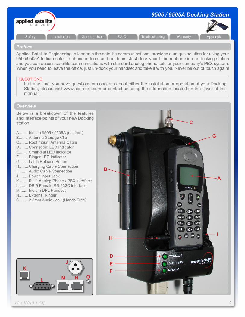
PrefaceApplied Satellite Engineering, a leader in the satellite communications, provides a unique solution for using your 9505/9505A Iridium satellite phone indoors and outdoors. Just dock your Iridium phone in our docking station and you can access satellite communications with standard analog phone sets or your company’s PBX system. When you need to leave the office, just un-dock your handset and take it with you. Never be out of touch again!
QUESTIONSIf at any time, you have questions or concerns about either the installation or operation of your Docking Station, please visit www.ase-corp.com or contact us using the information located on the cover of this manual.
Iridium 9505 / 9505A (not incl.) Antenna Storage Clip Roof mount Antenna Cable Connected LED Indicator Smartdial LED Indicator Ringer LED Indicator Latch Release Button Charging Cable Connection Audio Cable Connection Power Input Jack RJ11 Analog Phone / PBX interface DB-9 Female RS-232C interface Iridium DPL Handset External Ringer 2.5mm Audio Jack (Hands Free)
A........ B........ C........ D........ E........ F........ G........ H........ I........ J........ K........ L....... M........ N........ O........
Below is a breakdown of the features and Interface points of your new Docking station.
A
C
B
DEF
G
HI
JK
L M N O
Installation General Use F.A.Q. WarrantyTroubleshooting AppendixSafety
V2.1 [2013-1-14] 3
9505 / 9505A Docking Station
Safety
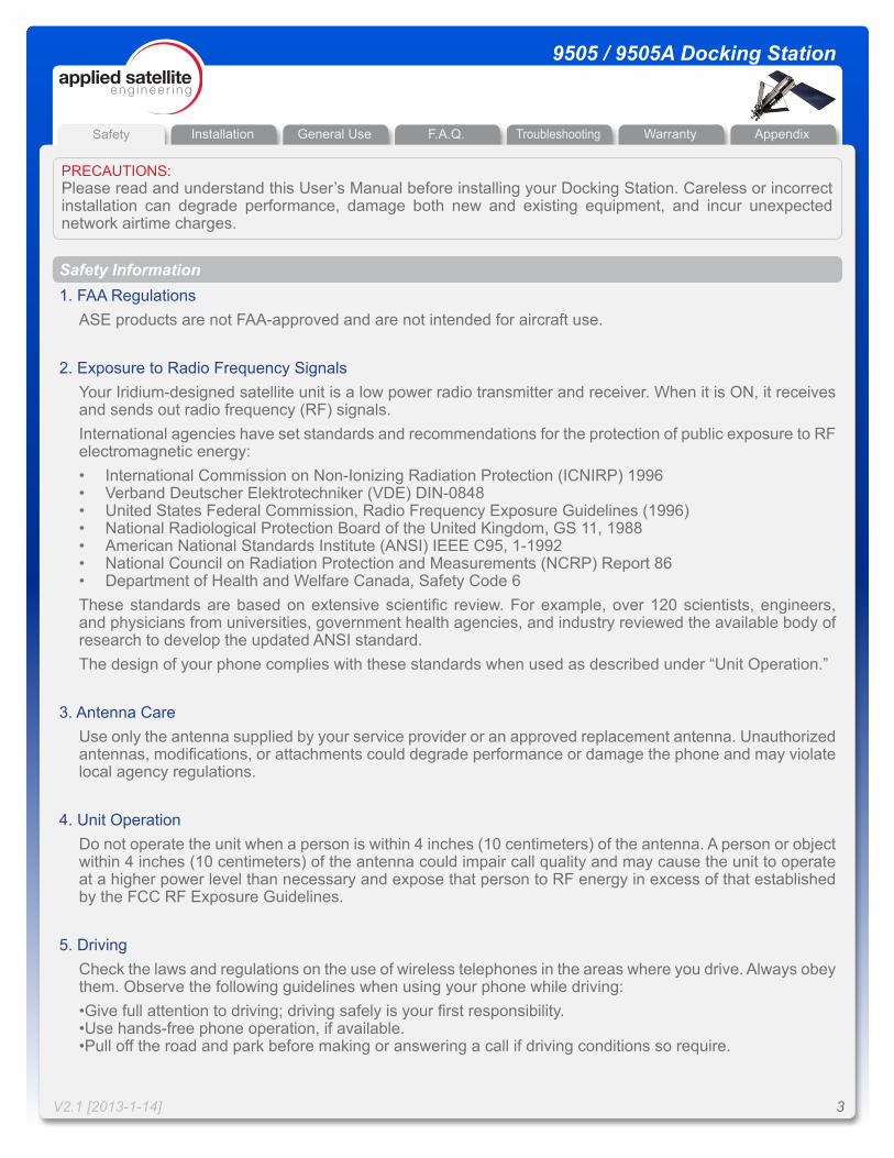
PRECAUTIONS: Please read and understand this User’s Manual before installing your Docking Station. Careless or incorrect installation can degrade performance, damage both new and existing equipment, and incur unexpected network airtime charges.
Safety Information1. FAA Regulations
ASE products are not FAA-approved and are not intended for aircraft use.
2. Exposure to Radio Frequency SignalsYour Iridium-designed satellite unit is a low power radio transmitter and receiver. When it is ON, it receives and sends out radio frequency (RF) signals.International agencies have set standards and recommendations for the protection of public exposure to RF electromagnetic energy:• International Commission on Non-Ionizing Radiation Protection (ICNIRP) 1996• Verband Deutscher Elektrotechniker (VDE) DIN-0848• United States Federal Commission, Radio Frequency Exposure Guidelines (1996)• National Radiological Protection Board of the United Kingdom, GS 11, 1988• American National Standards Institute (ANSI) IEEE C95, 1-1992• National Council on Radiation Protection and Measurements (NCRP) Report 86• Department of Health and Welfare Canada, Safety Code 6These standards are based on extensive scientific review. For example, over 120 scientists, engineers, and physicians from universities, government health agencies, and industry reviewed the available body of research to develop the updated ANSI standard.The design of your phone complies with these standards when used as described under “Unit Operation.”
3. Antenna CareUse only the antenna supplied by your service provider or an approved replacement antenna. Unauthorized antennas, modifications, or attachments could degrade performance or damage the phone and may violate local agency regulations.
4. Unit OperationDo not operate the unit when a person is within 4 inches (10 centimeters) of the antenna. A person or object within 4 inches (10 centimeters) of the antenna could impair call quality and may cause the unit to operate at a higher power level than necessary and expose that person to RF energy in excess of that established by the FCC RF Exposure Guidelines.
5. DrivingCheck the laws and regulations on the use of wireless telephones in the areas where you drive. Always obey them. Observe the following guidelines when using your phone while driving:•Give full attention to driving; driving safely is your first responsibility.•Use hands-free phone operation, if available.•Pull off the road and park before making or answering a call if driving conditions so require.
Installation General Use F.A.Q. WarrantyTroubleshooting AppendixSafety
V2.1 [2013-1-14] 4
9505 / 9505A Docking Station
Safety
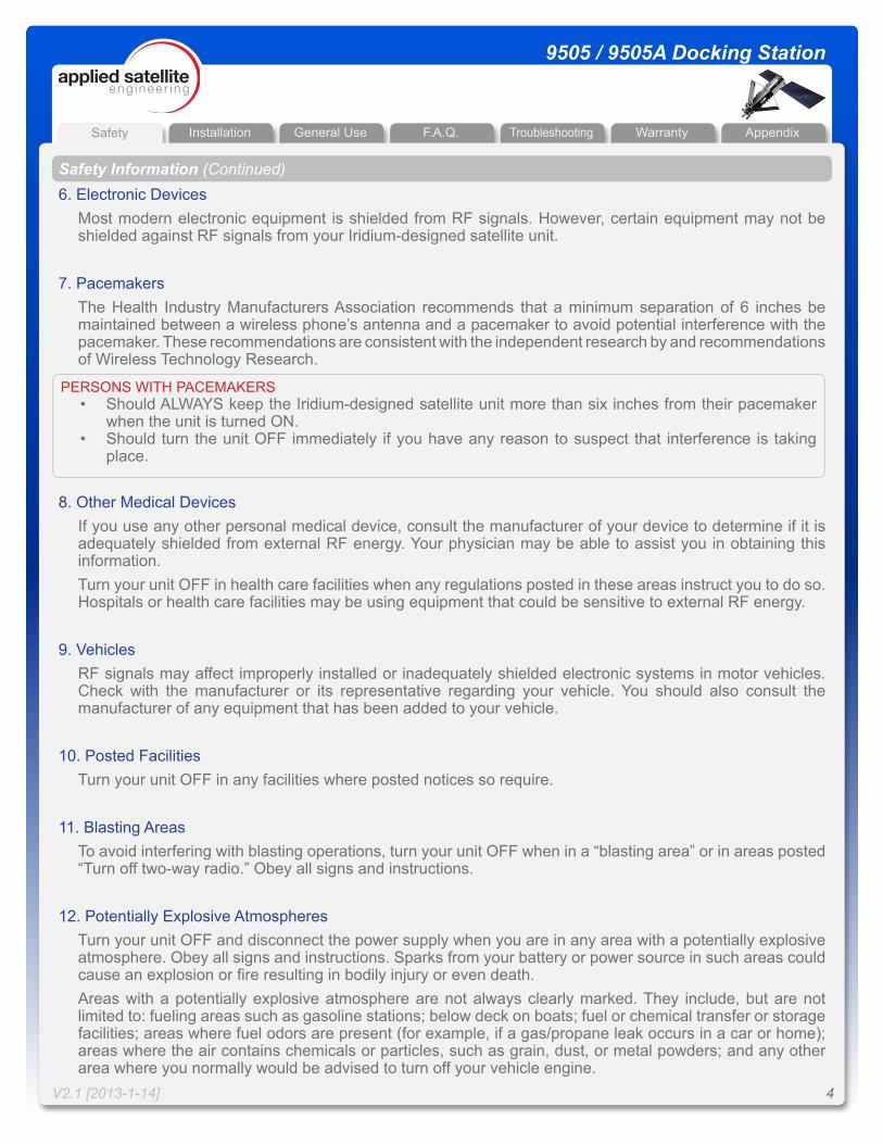
Safety Information (Continued)6. Electronic Devices
Most modern electronic equipment is shielded from RF signals. However, certain equipment may not be shielded against RF signals from your Iridium-designed satellite unit.
7. PacemakersThe Health Industry Manufacturers Association recommends that a minimum separation of 6 inches be maintained between a wireless phone’s antenna and a pacemaker to avoid potential interference with the pacemaker. These recommendations are consistent with the independent research by and recommendations of Wireless Technology Research.
8. Other Medical DevicesIf you use any other personal medical device, consult the manufacturer of your device to determine if it is adequately shielded from external RF energy. Your physician may be able to assist you in obtaining this information.Turn your unit OFF in health care facilities when any regulations posted in these areas instruct you to do so. Hospitals or health care facilities may be using equipment that could be sensitive to external RF energy.
9. VehiclesRF signals may affect improperly installed or inadequately shielded electronic systems in motor vehicles. Check with the manufacturer or its representative regarding your vehicle. You should also consult the manufacturer of any equipment that has been added to your vehicle.
10. Posted FacilitiesTurn your unit OFF in any facilities where posted notices so require.
11. Blasting AreasTo avoid interfering with blasting operations, turn your unit OFF when in a “blasting area” or in areas posted “Turn off two-way radio.” Obey all signs and instructions.
12. Potentially Explosive AtmospheresTurn your unit OFF and disconnect the power supply when you are in any area with a potentially explosive atmosphere. Obey all signs and instructions. Sparks from your battery or power source in such areas could cause an explosion or fire resulting in bodily injury or even death.Areas with a potentially explosive atmosphere are not always clearly marked. They include, but are not limited to: fueling areas such as gasoline stations; below deck on boats; fuel or chemical transfer or storage facilities; areas where fuel odors are present (for example, if a gas/propane leak occurs in a car or home); areas where the air contains chemicals or particles, such as grain, dust, or metal powders; and any other area where you normally would be advised to turn off your vehicle engine.
PERSONS WITH PACEMAKERS• Should ALWAYS keep the Iridium-designed satellite unit more than six inches from their pacemaker
when the unit is turned ON.• Should turn the unit OFF immediately if you have any reason to suspect that interference is taking
place.
Installation General Use F.A.Q. WarrantyTroubleshooting AppendixSafety
V2.1 [2013-1-14] 5
9505 / 9505A Docking Station
Safety
Safety Information (Continued)13. For Vehicles Equipped With Airbags
An air bag inflates with great force. Do NOT place objects, including both installed or portable wireless equipment, in the area over the air bag or in the air bag deployment area. If in-vehicle wireless equipment is improperly installed and the air bag inflates, serious injury could result.
14. Important Notes for PBX System UsersIf using the Docking Station with a PBX system, three precautions must be followed to prevent damage to your unit.1. The Docking Station functions as a central office (i.e., the Docking Station emulates the wall jack by
generating the high operating and ring voltages). Do not connect the Docking Station as an extension.2. When connecting the Docking Station to the PBX, it needs to be connected as analog only. Connecting
the Docking Station as other than analog may result in damage to the RJ11 interface.3. Do not try to ring the Docking Station as if it were an extension on the PBX system. The Docking Station
has a built-in ringer so that when a call is received, the unit will ring to alarm that a call is coming in. Trying to ring the Docking Station unit from the PBX system could result in damage to the RJ11 interface.
Installation General Use F.A.Q. WarrantyTroubleshooting AppendixSafety
V2.1 [2013-1-14] 6
9505 / 9505A Docking Station
Installation
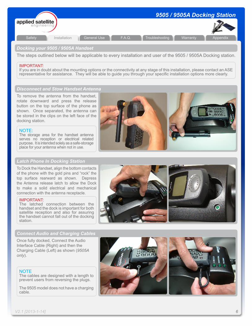
To remove the antenna from the handset, rotate downward and press the release button on the top surface of the phone as shown. Once separated, the antenna can be stored in the clips on the left face of the docking station.
NOTE:The storage area for the handset antenna serves no reception or electrical related purpose. It is intended solely as a safe-storage place for your antenna when not in use.
To Dock the Handset, align the bottom contacts of the phone with the gold pins and “rock” the top surface rearward as shown. Depress the Antenna release latch to allow the Dock to make a solid electrical and mechanical connection with the antenna receptacle.
IMPORTANT: The latched connection between the handset and the dock is important for both satellite reception and also for assuring the handset cannot fall out of the docking station.
Once fully docked, Connect the Audio Interface Cable (Right) and then the Charging Cable (Left) as shown (9505A only).
NOTEThe cables are designed with a length to prevent users from reversing the plugs.
The 9505 model does not have a charging cable.
Docking your 9505 / 9505A HandsetThe steps outlined below will be applicable to every installation and user of the 9505 / 9505A Docking station.
Disconnect and Stow Handset Antenna
Latch Phone In Docking Station
Connect Audio and Charging Cables
IMPORTANT: If you are in doubt about the mounting options or the connectivity at any stage of this installation, please contact an ASE representative for assistance. They will be able to guide you through your specific installation options more clearly.
Installation General Use F.A.Q. WarrantyTroubleshooting AppendixSafety
V2.1 [2013-1-14] 7
9505 / 9505A Docking Station
Installation
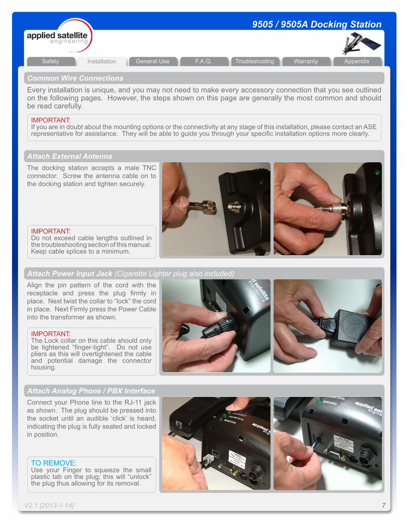
The docking station accepts a male TNC connector. Screw the antenna cable on to the docking station and tighten securely.
IMPORTANT: Do not exceed cable lengths outlined in the troubleshooting section of this manual. Keep cable splices to a minimum.
Align the pin pattern of the cord with the receptacle and press the plug firmly in place. Next twist the collar to “lock” the cord in place. Next Firmly press the Power Cable into the transformer as shown.
Common Wire ConnectionsEvery installation is unique, and you may not need to make every accessory connection that you see outlined on the following pages. However, the steps shown on this page are generally the most common and should be read carefully.
IMPORTANT: If you are in doubt about the mounting options or the connectivity at any stage of this installation, please contact an ASE representative for assistance. They will be able to guide you through your specific installation options more clearly.
IMPORTANT: The Lock collar on this cable should only be tightened “finger-tight”. Do not use pliers as this will overtightened the cable and potential damage the connector housing.
Connect your Phone line to the RJ-11 jack as shown. The plug should be pressed into the socket until an audible ‘click’ is heard, indicating the plug is fully seated and locked in position.
TO REMOVE:Use your Finger to squeeze the small plastic tab on the plug; this will “unlock” the plug thus allowing for its removal.
Attach External Antenna
Attach Power Input Jack (Cigarette Lighter plug also included)
Attach Analog Phone / PBX Interface
Installation General Use F.A.Q. WarrantyTroubleshooting AppendixSafety
V2.1 [2013-1-14] 8
9505 / 9505A Docking Station
Installation
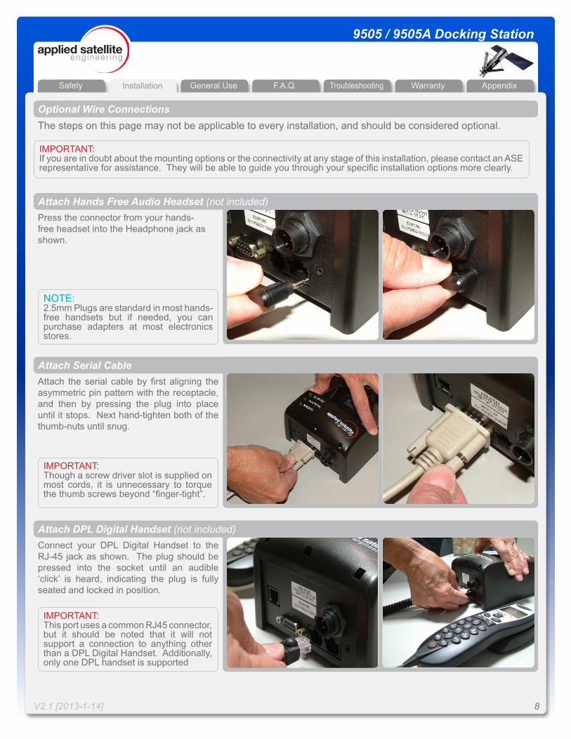
Press the connector from your hands-free headset into the Headphone jack as shown.
NOTE:2.5mm Plugs are standard in most hands-free handsets but if needed, you can purchase adapters at most electronics stores.
Optional Wire ConnectionsThe steps on this page may not be applicable to every installation, and should be considered optional.
Attach Hands Free Audio Headset (not included)
Attach the serial cable by first aligning the asymmetric pin pattern with the receptacle, and then by pressing the plug into place until it stops. Next hand-tighten both of the thumb-nuts until snug.
IMPORTANT: Though a screw driver slot is supplied on most cords, it is unnecessary to torque the thumb screws beyond “finger-tight”.
Attach Serial Cable
Connect your DPL Digital Handset to the RJ-45 jack as shown. The plug should be pressed into the socket until an audible ‘click’ is heard, indicating the plug is fully seated and locked in position.
IMPORTANT: This port uses a common RJ45 connector, but it should be noted that it will not support a connection to anything other than a DPL Digital Handset. Additionally, only one DPL handset is supported
Attach DPL Digital Handset (not included)
IMPORTANT: If you are in doubt about the mounting options or the connectivity at any stage of this installation, please contact an ASE representative for assistance. They will be able to guide you through your specific installation options more clearly.
Installation General Use F.A.Q. WarrantyTroubleshooting AppendixSafety
V2.1 [2013-1-14] 9
9505 / 9505A Docking Station
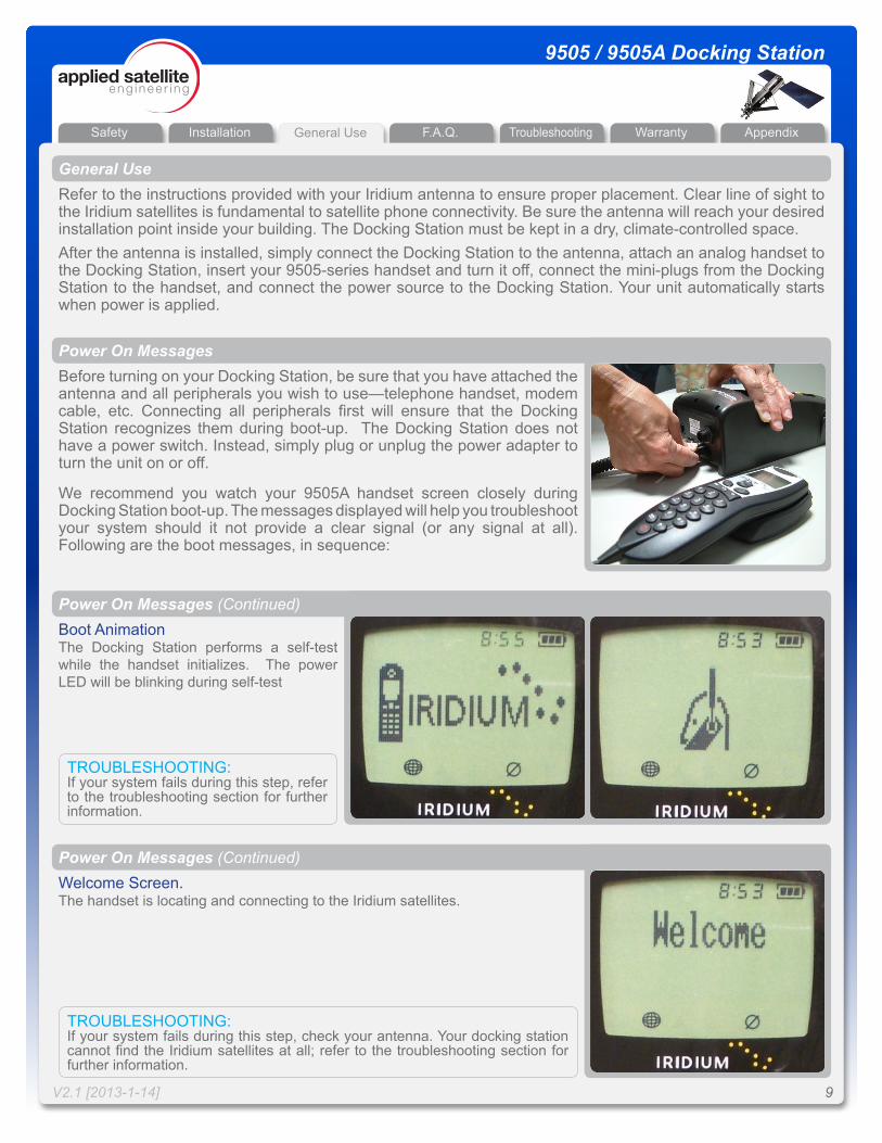
Boot AnimationThe Docking Station performs a self-test while the handset initializes. The power LED will be blinking during self-test
General UseRefer to the instructions provided with your Iridium antenna to ensure proper placement. Clear line of sight to the Iridium satellites is fundamental to satellite phone connectivity. Be sure the antenna will reach your desired installation point inside your building. The Docking Station must be kept in a dry, climate-controlled space.After the antenna is installed, simply connect the Docking Station to the antenna, attach an analog handset to the Docking Station, insert your 9505-series handset and turn it off, connect the mini-plugs from the Docking Station to the handset, and connect the power source to the Docking Station. Your unit automatically starts when power is applied.
Before turning on your Docking Station, be sure that you have attached the antenna and all peripherals you wish to use—telephone handset, modem cable, etc. Connecting all peripherals first will ensure that the Docking Station recognizes them during boot-up. The Docking Station does not have a power switch. Instead, simply plug or unplug the power adapter to turn the unit on or off.
We recommend you watch your 9505A handset screen closely during Docking Station boot-up. The messages displayed will help you troubleshoot your system should it not provide a clear signal (or any signal at all). Following are the boot messages, in sequence:
Power On Messages
TROUBLESHOOTING:If your system fails during this step, refer to the troubleshooting section for further information.
Power On Messages (Continued)
Welcome Screen.The handset is locating and connecting to the Iridium satellites.
TROUBLESHOOTING:If your system fails during this step, check your antenna. Your docking station cannot find the Iridium satellites at all; refer to the troubleshooting section for further information.
Power On Messages (Continued)
General Use
Installation General Use F.A.Q. WarrantyTroubleshooting AppendixSafety
V2.1 [2013-1-14] 10
9505 / 9505A Docking Station
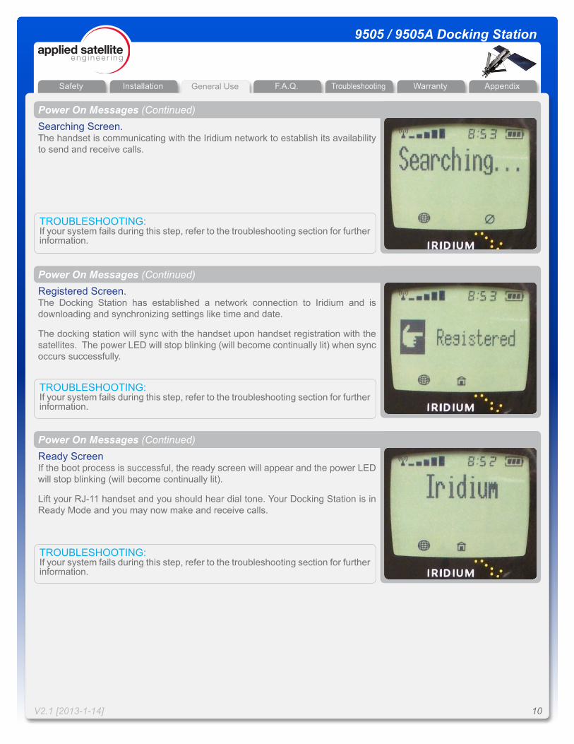
Searching Screen.The handset is communicating with the Iridium network to establish its availability to send and receive calls.
TROUBLESHOOTING:If your system fails during this step, refer to the troubleshooting section for further information.
Power On Messages (Continued)
Registered Screen.The Docking Station has established a network connection to Iridium and is downloading and synchronizing settings like time and date.
The docking station will sync with the handset upon handset registration with the satellites. The power LED will stop blinking (will become continually lit) when sync occurs successfully.
TROUBLESHOOTING:If your system fails during this step, refer to the troubleshooting section for further information.
Power On Messages (Continued)
Ready ScreenIf the boot process is successful, the ready screen will appear and the power LED will stop blinking (will become continually lit).
Lift your RJ-11 handset and you should hear dial tone. Your Docking Station is in Ready Mode and you may now make and receive calls.
TROUBLESHOOTING:If your system fails during this step, refer to the troubleshooting section for further information.
Power On Messages (Continued)
General Use
Installation General Use F.A.Q. WarrantyTroubleshooting AppendixSafety
V2.1 [2013-1-14] 11
9505 / 9505A Docking Station
Making a Call - What You Will Hear (RJ-11 Interface)The first thing you hear is dial tone. You may notice that the tone is a slightly higher pitch than the dial tone you are used to. While you are connecting, you will not hear a ring, but instead a short beep. If the call fails during connection, you will hear a rapid beeping—try your call again. If the line you are calling is busy, you will hear a normal busy signal.
General Use
SEQUENCE
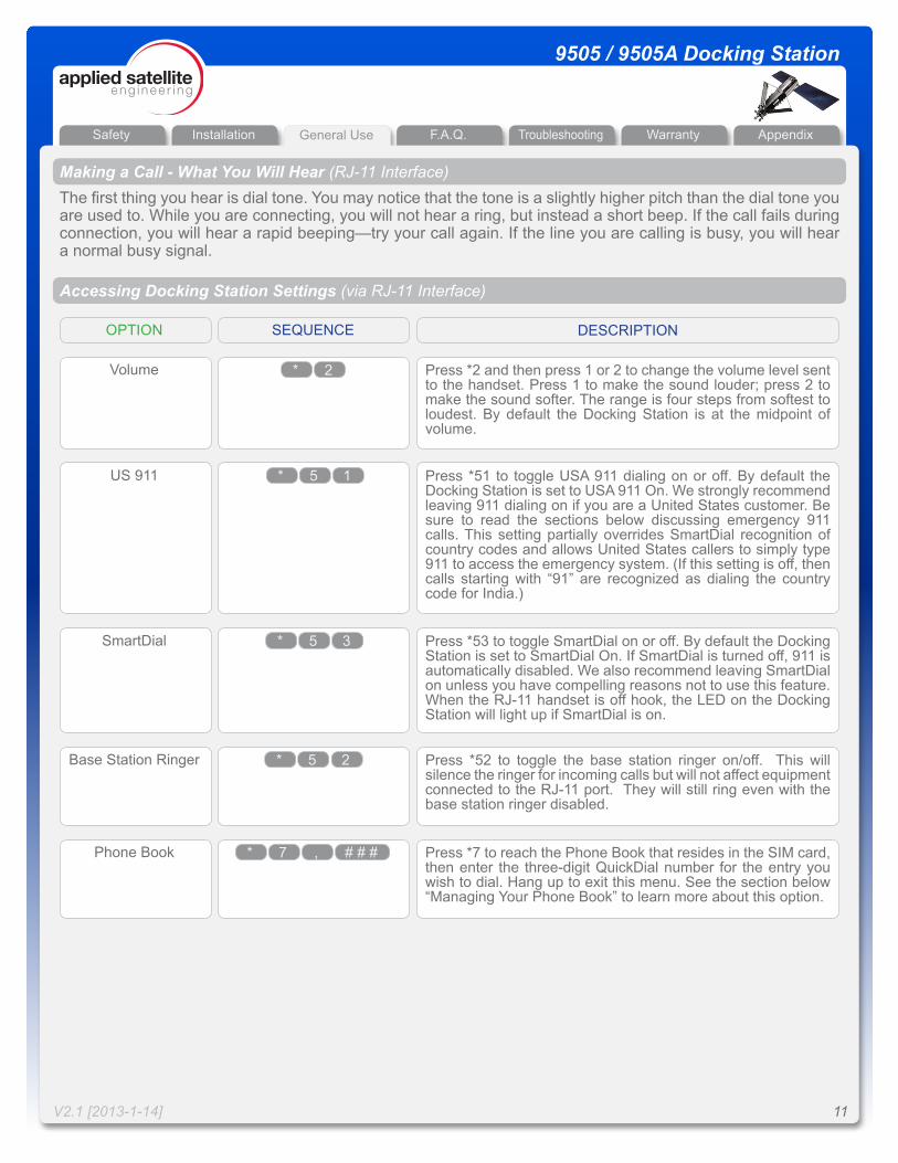
Accessing Docking Station Settings (via RJ-11 Interface)
OPTION DESCRIPTION
Volume Press *2 and then press 1 or 2 to change the volume level sent to the handset. Press 1 to make the sound louder; press 2 to make the sound softer. The range is four steps from softest to loudest. By default the Docking Station is at the midpoint of volume.
US 911 Press *51 to toggle USA 911 dialing on or off. By default the Docking Station is set to USA 911 On. We strongly recommend leaving 911 dialing on if you are a United States customer. Be sure to read the sections below discussing emergency 911 calls. This setting partially overrides SmartDial recognition of country codes and allows United States callers to simply type 911 to access the emergency system. (If this setting is off, then calls starting with “91” are recognized as dialing the country code for India.)
SmartDial Press *53 to toggle SmartDial on or off. By default the Docking Station is set to SmartDial On. If SmartDial is turned off, 911 is automatically disabled. We also recommend leaving SmartDial on unless you have compelling reasons not to use this feature. When the RJ-11 handset is off hook, the LED on the Docking Station will light up if SmartDial is on.
Base Station Ringer Press *52 to toggle the base station ringer on/off. This will silence the ringer for incoming calls but will not affect equipment connected to the RJ-11 port. They will still ring even with the base station ringer disabled.
* 2
* 5 1
* 5 3
* 5 2
Phone Book Press *7 to reach the Phone Book that resides in the SIM card, then enter the three-digit QuickDial number for the entry you wish to dial. Hang up to exit this menu. See the section below “Managing Your Phone Book” to learn more about this option.
# # #* 7 ,
Installation General Use F.A.Q. WarrantyTroubleshooting AppendixSafety
V2.1 [2013-1-14] 12
9505 / 9505A Docking Station
Calling Without SmartDialWithout SmartDial, you must follow a different dialing sequence:1. Lift the receiver to go off-hook.2. Enter 0 0 (zero zero).3. Enter the country code.4. Enter the area code and telephone number.5. Enter # to place call.The Docking Station does not recognize country codes or number string lengths with SmartDial off. You must enter all digits correctly and press # to initiate the call—the Docking Station does not automatically dial with SmartDial off.
General Use
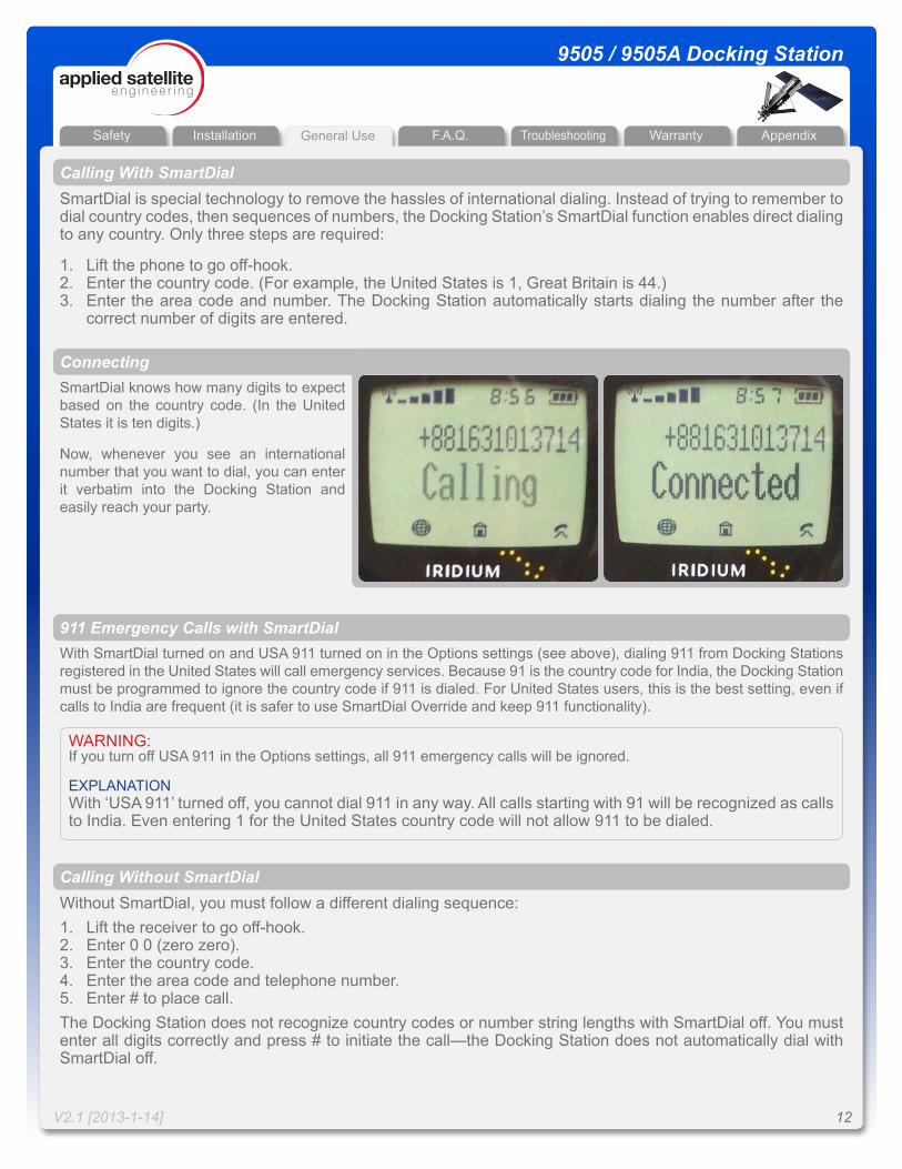
SmartDial knows how many digits to expect based on the country code. (In the United States it is ten digits.)
Now, whenever you see an international number that you want to dial, you can enter it verbatim into the Docking Station and easily reach your party.
SmartDial is special technology to remove the hassles of international dialing. Instead of trying to remember to dial country codes, then sequences of numbers, the Docking Station’s SmartDial function enables direct dialing to any country. Only three steps are required:
1. Lift the phone to go off-hook.2. Enter the country code. (For example, the United States is 1, Great Britain is 44.)3. Enter the area code and number. The Docking Station automatically starts dialing the number after the
correct number of digits are entered.
Calling With SmartDial
Connecting
With SmartDial turned on and USA 911 turned on in the Options settings (see above), dialing 911 from Docking Stations registered in the United States will call emergency services. Because 91 is the country code for India, the Docking Station must be programmed to ignore the country code if 911 is dialed. For United States users, this is the best setting, even if calls to India are frequent (it is safer to use SmartDial Override and keep 911 functionality).
WARNING:If you turn off USA 911 in the Options settings, all 911 emergency calls will be ignored.
EXPLANATIONWith ‘USA 911’ turned off, you cannot dial 911 in any way. All calls starting with 91 will be recognized as calls to India. Even entering 1 for the United States country code will not allow 911 to be dialed.
911 Emergency Calls with SmartDial
Installation General Use F.A.Q. WarrantyTroubleshooting AppendixSafety
V2.1 [2013-1-14] 13
9505 / 9505A Docking Station
If you are using SmartDial and want to override it temporarily, one extra step is needed:
1. Lift the receiver to go off-hook.2. Enter 0 (zero) to leave SmartDial.3. Enter 0 0 (zero, zero).4. Enter the country code.5. Enter the area code and telephone number.6. Enter # to place call.
Temporarily Overriding SmartDial
With SmartDial off, dialing United States 911 is not disabled, but you must still enter # to send the number and make the connection. To clarify: without SmartDial, you must enter 911# to reach emergency services.
911 Emergency Calls without SmartDial
The Docking Station has a built-in ringer to alert you to an incoming call. Your handset probably also has a ringer, so you may wish to turn it off. The Docking Station has an internal ringer that can be silenced by pressing *52.
When a call comes in, simply use your handset like you normally would. Speak in a regular tone of voice. You should find most of your calls are at least as clear as a cellular phone call and often as clear as a standard wire-line phone call. The only minor difference in receiving a Docking Station call is this: when the caller at the other end disconnects, if you continue to hold your receiver off-hook you will get a dial tone. Be sure to hang up your handset normally.
Answering a Call
General Use
Installation General Use F.A.Q. WarrantyTroubleshooting AppendixSafety
V2.1 [2013-1-14] 14
9505 / 9505A Docking Station
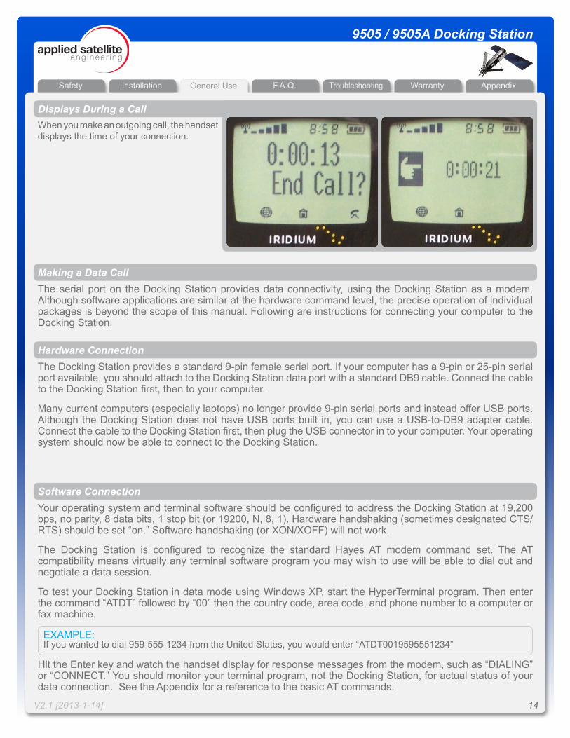
When you make an outgoing call, the handset displays the time of your connection.
Making a Data CallThe serial port on the Docking Station provides data connectivity, using the Docking Station as a modem. Although software applications are similar at the hardware command level, the precise operation of individual packages is beyond the scope of this manual. Following are instructions for connecting your computer to the Docking Station.
The Docking Station provides a standard 9-pin female serial port. If your computer has a 9-pin or 25-pin serial port available, you should attach to the Docking Station data port with a standard DB9 cable. Connect the cable to the Docking Station first, then to your computer.
Many current computers (especially laptops) no longer provide 9-pin serial ports and instead offer USB ports. Although the Docking Station does not have USB ports built in, you can use a USB-to-DB9 adapter cable. Connect the cable to the Docking Station first, then plug the USB connector in to your computer. Your operating system should now be able to connect to the Docking Station.
Hardware Connection
Displays During a Call
General Use
Your operating system and terminal software should be configured to address the Docking Station at 19,200 bps, no parity, 8 data bits, 1 stop bit (or 19200, N, 8, 1). Hardware handshaking (sometimes designated CTS/RTS) should be set “on.” Software handshaking (or XON/XOFF) will not work.
The Docking Station is configured to recognize the standard Hayes AT modem command set. The AT compatibility means virtually any terminal software program you may wish to use will be able to dial out and negotiate a data session.
To test your Docking Station in data mode using Windows XP, start the HyperTerminal program. Then enter the command “ATDT” followed by “00” then the country code, area code, and phone number to a computer or fax machine.
Hit the Enter key and watch the handset display for response messages from the modem, such as “DIALING” or “CONNECT.” You should monitor your terminal program, not the Docking Station, for actual status of your data connection. See the Appendix for a reference to the basic AT commands.
Software Connection
EXAMPLE:If you wanted to dial 959-555-1234 from the United States, you would enter “ATDT0019595551234”
Installation General Use F.A.Q. WarrantyTroubleshooting AppendixSafety
V2.1 [2013-1-14] 15
9505 / 9505A Docking Station
For Integrators OnlyASE has developed a set of extended communications commands to aid Docking Station developers. These XT commands let programmers parse the data stream for GPS information, current equipment status, etc. See the Appendix for descriptions of the XT commands.
The following are ways to add, edit, and delete entries from your Docking Station Phone Book:
1. Remove your 9505A handset from the Docking Station. Use the handset’s built-in menu functions to modify your Phone Book. (Note that when adding numbers, each entry must start with a “+” which is entered by holding down the 0 key until the + appears.) Replace the handset in your Docking Station and your new Phone Book will be accessible.
2. Put the SIM chip from your Docking Station handset into another 9505A handset, save your entries to the Phone Book, and replace the SIM chip. ASE discourages SIM chip swapping due to the chance of damage either to the SIM chip or the hardware.
Since the Docking Station is usually used remotely, you will need to either memorize your QuickDial numbers or keep a written list of your Phone Book entries for reference.
Managing Your Phone Book
General Use
Installation General Use F.A.Q. WarrantyTroubleshooting AppendixSafety
V2.1 [2013-1-14] 16
9505 / 9505A Docking Station
F.A.Q.
SOLUTION: Your service provider will give you your Iridium phone number. Callers simply dial 011 (to reach an international line), then your Iridium number (starting with 8816). You might want to point out that your Iridium number does not follow standard United States format. There are 12 digits in your Iridium number.
QUESTION: How do callers dial in order to reach my Docking Station?
SOLUTION: Yes, answering machines operate correctly with the Docking Station. Just attach the answering machine to the RJ11 jack on the Docking Station unit as if you were plugging into the wall jack; then connect the rest of your equipment as described in the answering machine user’s guide.
QUESTION: Can I use an answering machine with the Docking Station?
Frequently Asked Questions
SOLUTION: No, fax machines will not function with the Docking Station due to shortcomings in satellite technology. However, Iridium offers a fax adapter that will allow you to use your Iridium phone with a fax machine. Contact your service provider for more information.
QUESTION: Can I use a fax machine with the Docking Station?
Installation General Use F.A.Q. WarrantyTroubleshooting AppendixSafety
V2.1 [2013-1-14] 17
9505 / 9505A Docking Station
Troubleshooting
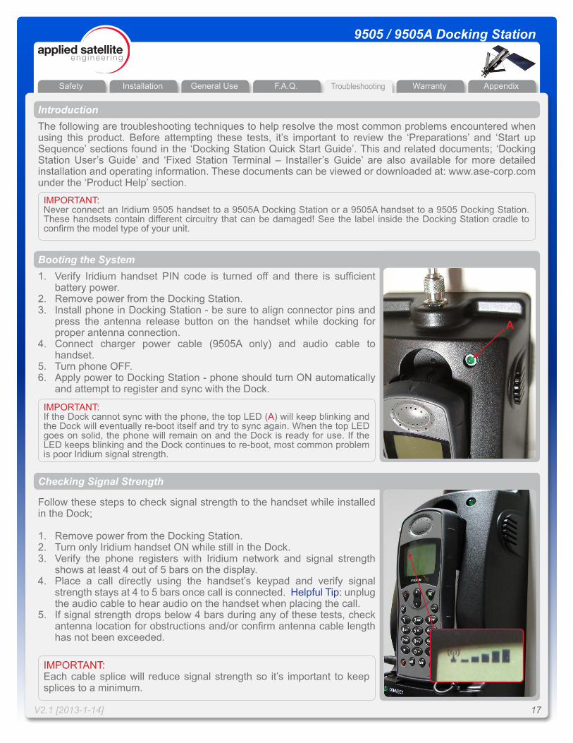
IMPORTANT: If the Dock cannot sync with the phone, the top LED (A) will keep blinking and the Dock will eventually re-boot itself and try to sync again. When the top LED goes on solid, the phone will remain on and the Dock is ready for use. If the LED keeps blinking and the Dock continues to re-boot, most common problem is poor Iridium signal strength.
Checking Signal Strength
Follow these steps to check signal strength to the handset while installed in the Dock;
1. Remove power from the Docking Station.2. Turn only Iridium handset ON while still in the Dock.3. Verify the phone registers with Iridium network and signal strength
shows at least 4 out of 5 bars on the display.4. Place a call directly using the handset’s keypad and verify signal
strength stays at 4 to 5 bars once call is connected. Helpful Tip: unplug the audio cable to hear audio on the handset when placing the call.
5. If signal strength drops below 4 bars during any of these tests, check antenna location for obstructions and/or confirm antenna cable length has not been exceeded.
1. Verify Iridium handset PIN code is turned off and there is sufficient battery power.
2. Remove power from the Docking Station.3. Install phone in Docking Station - be sure to align connector pins and
press the antenna release button on the handset while docking for proper antenna connection.
4. Connect charger power cable (9505A only) and audio cable to handset.
5. Turn phone OFF.6. Apply power to Docking Station - phone should turn ON automatically
and attempt to register and sync with the Dock.
Booting the System
IMPORTANT:Each cable splice will reduce signal strength so it’s important to keep splices to a minimum.
IntroductionThe following are troubleshooting techniques to help resolve the most common problems encountered when using this product. Before attempting these tests, it’s important to review the ‘Preparations’ and ‘Start up Sequence’ sections found in the ‘Docking Station Quick Start Guide’. This and related documents; ‘Docking Station User’s Guide’ and ‘Fixed Station Terminal – Installer’s Guide’ are also available for more detailed installation and operating information. These documents can be viewed or downloaded at: www.ase-corp.com under the ‘Product Help’ section.
IMPORTANT: Never connect an Iridium 9505 handset to a 9505A Docking Station or a 9505A handset to a 9505 Docking Station. These handsets contain different circuitry that can be damaged! See the label inside the Docking Station cradle to confirm the model type of your unit.
A
Installation General Use F.A.Q. WarrantyTroubleshooting AppendixSafety
V2.1 [2013-1-14] 18
9505 / 9505A Docking Station
Troubleshooting
CAUSE: Docking Station is unable to synchronize with the handset and Iridium network.
RESOLUTION: Re-seat the handset in the Dock, verify docked handset has the PIN code turned OFF, check antenna signal strength.
Installation and Startup Troubleshooting
SYMPTOM: Power LED never stays on solid and continues to blink, system keeps re-booting
CAUSE: Another symptom that the Dock cannot sync with the Iridium network.
RESOLUTION: Re-seat the handset in the Dock, verify docked handset has the PIN code turned OFF, check antenna signal strength.
SYMPTOM: Busy Signal present on RJ-11 analog phone
CAUSE: Dock cannot communicate with the handset. Connector pins in the Dock could possibly be bent or out of alignment.
RESOLUTION: Remove handset from Dock and visually inspect connector pins. If necessary, pins can be adjusted (carefully) using needle-noose pliers.
SYMPTOM: System will not sync even with known good signal strength.
CAUSE: This is an automatic feature of the Dock which keeps the handset registered on the Iridium network for incoming calls.
RESOLUTION: If this feature is not desired, it can be disabled by sending a command via the data port (see User’s Manual).
SYMPTOM: System re-boots every 24 hours
CAUSE: Check antenna location for obstructions, a 360 degree clear view of the sky is required for proper operation. Antenna cable length exceeded or there are too many splices in cable run.
RESOLUTION: Re-position antenna away from obstructions, verify cable length has not been exceeded, eliminate unnecessary cable splices.
SYMPTOM: Signal strength drops when a call is placed
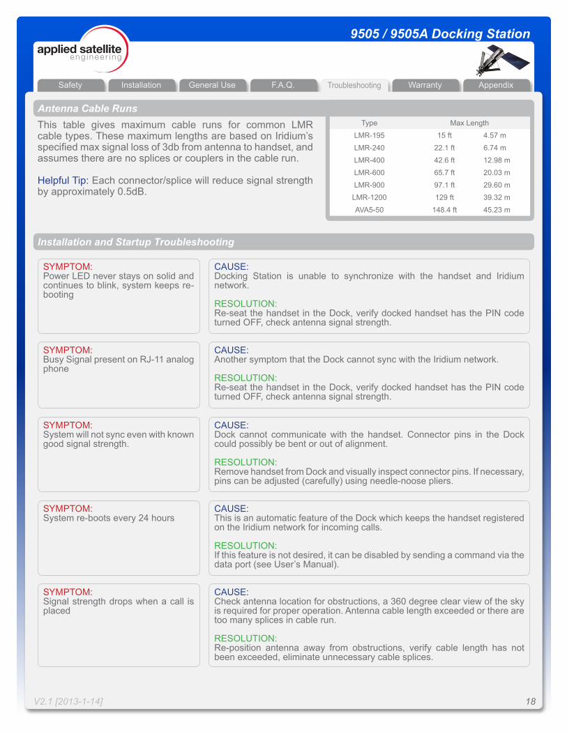
Antenna Cable RunsThis table gives maximum cable runs for common LMR cable types. These maximum lengths are based on Iridium’s specified max signal loss of 3db from antenna to handset, and assumes there are no splices or couplers in the cable run.
Helpful Tip: Each connector/splice will reduce signal strength by approximately 0.5dB.
Type Max Length
LMR-195 15 ft 4.57 m
LMR-240 22.1 ft 6.74 m
LMR-400 42.6 ft 12.98 m
LMR-600 65.7 ft 20.03 m
LMR-900 97.1 ft 29.60 m
LMR-1200 129 ft 39.32 m
AVA5-50 148.4 ft 45.23 m
Installation General Use F.A.Q. WarrantyTroubleshooting AppendixSafety
V2.1 [2013-1-14] 19
9505 / 9505A Docking Station
Warranty
ASE Limited Warranty
1. Coverage and DurationApplied Satellite Engineering, Inc. (ASE) warrants that its new satellite subscriber radiotelephone products and accessories (the “Product”) shall be free from defects in materials and workmanship for a period of twelve (12) months from the date such Product is delivered to the first end-user purchaser or first lessee (the “Purchaser”), or the date such Products are first placed into satellite subscriber service, whichever occurs earliest. ASE, at its option, shall at no charge to Purchaser, either repair or replace the Product, or refund the purchase price of a Product that does not conform to this warranty, provided the Product is returned in accordance with the instructions set out below and within the warranty period. These remedies are Purchaser’s exclusive remedies under this warranty. Repair may include the replacement of parts or boards with functionally equivalent reconditioned or new parts or boards. A Product that has been repaired or replaced is warranted for the balance of the original warranty period. A Product for which a replacement has been provided shall become ASE’s property.This warranty is made by ASE to the Purchaser of the Products only, and it is not assignable or transferable by the Purchaser. This is ASE’s sole and complete warranty for the Products. ASE assumes no obligation or liability for additions or modifications to this warranty unless made in writing and signed by an officer of ASE. ASE does not warrant any installation, maintenance, or service of the Products not performed by ASE.This product is covered by a U.S.A. warranty. If the Product has been sold outside of the U.S.A., ASE will honor the U.S.A. warranty terms and conditions only. Outside of the U.S.A., any different warranty terms, liabilities, and/or legal requirements of the country in which the Product is sold are specifically disclaimed by ASE.
2. Conditions Not Covered By This Warrantya) Products that are integrated, installed, maintained, or serviced in any manner other than in accordance with the ASE user documentation furnished with or applicable to the Product.b) Product damage caused by the use of ancillary equipment not furnished by ASE, including accessories and peripherals. c) Problems where the Product is used in a combination with ancillary equipment not furnished by ASE and it is determined by ASE there is no fault with the Product.d) Ancillary equipment not furnished by ASE that is attached to or used in connection with the Products is not the responsibility of ASE, and all such equipment is expressly excluded from this warranty. Furthermore, ASE does not warrant the integrated operation of the combination of the Products with any ancillary equipment not furnished by ASE.e) Defects or damage resulting from: use of the Product in any manner not normal or customary; misuse, accident, or neglect, including but not limited to dropping the Product onto hard surfaces, immersion in or exposure to water, rain or extreme humidity, immersion in or exposure to sand, dirt, or other particulates, exposure to extreme heat, spills of food or liquid; improper testing, operation, maintenance, installation, adjustment; or any alteration or modification of any kind.f) Batteries manufactured by ASE and sold with Products whose capacity exceeds 80% of rated capacity are not covered. Batteries whose capacity falls below 80% of rated capacity, or that develop leakage, shall be considered non-conforming. This warranty is voided for batteries if: i) such batteries are charged by other than the ASE-approved battery charger specified for charging such batteries; ii) any seals on such batteries are broken or show evidence of tampering; iii) such batteries are used in equipment other than the Product for which they are specified; or iv) such batteries are charged and stored at temperatures greater than 60 degrees Celsius.g) Breakage or damage to antennas, or scratches or other damage to plastic surfaces or other externally exposed parts caused by Purchaser’s use.
Installation General Use F.A.Q. WarrantyTroubleshooting AppendixSafety
V2.1 [2013-1-14] 20
9505 / 9505A Docking Station
Warranty
ASE Limited Warranty (Continued)h) Products disassembled or repaired in such a manner as to adversely affect performance or prevent adequate inspection and testing to verify any warranty claim.i) Products on which serial numbers or date tags have been removed, altered, or obliterated.j) Coil cords that are stretched or on which the modular tab is broken; leather cases, which are covered under separate manufacturer’s warranties.k) Products rented on a month-to-month basis.l) Normal wear and tear.
3. Obtaining Warranty ServiceFor warranty questions, repairs, or for the return of Product, please call your Service Provider or Point-of-Sale, not ASE. Equipment needing service should be returned to your Service Provider or Point-of-Sale, not ASE. SERVICE WORK PERFORMED BY SERVICE CENTERS NOT AUTHORIZED BY ASE TO PERFORM SUCH WORK WILL VOID THIS WARRANTY.All products shipped to ASE’s authorized Warranty Service Center must be shipped with freight and insurance prepaid. Purchaser must include with the Product a bill of sale, a lease, or some other comparable proof of purchase, the name and location of the installation facility, if any, and most importantly, the Purchaser’s name, address, and telephone number and a written description of the problem. Product that is repaired or replaced under this warranty shall be returned to Purchaser at ASE’s expense for the freight and insurance, and at Purchaser’s expense for any applicable duties or other charges. If additional information is needed, please contact ASE at the address and phone number listed in Paragraph 6 below.
4. General ProvisionsTHIS WARRANTY IS GIVEN IN LIEU OF ALL OTHER WARRANTIES EXPRESS OR IMPLIED, INCLUDING BUT NOT LIMITED TO THE IMPLIED WARRANTIES OF MERCHANTABILITY AND FITNESS FOR A PARTICULAR PURPOSE. FURTHER, THIS WARRANTY COVERS THE PRODUCTS ONLY, AND NO WARRANTY IS MADE AS TO COVERAGE, AVAILABILITY, OR GRADE OF SERVICE PROVIDED BY ASE SEPARATELY FOR ASE SATELLITE SERVICES. IN NO EVENT SHALL ASE BE LIABLE FOR DAMAGES IN EXCESS OF THE PURCHASE PRICE OF THE PRODUCT IN QUESTION, OR FOR ANY LOSS OF USE, LOSS OF TIME, INCONVENIENCE, COMMERCIAL LOSS, LOST PROFITS OR SAVINGS OR OTHER INCIDENTAL, SPECIAL, OR CONSEQUENTIAL DAMAGES ARISING OUT OF THE USE OR INABILITY TO USE SUCH PRODUCT, TO THE FULL EXTENT SUCH MAY BE DISCLAIMED BY LAW.
5. State Law and Other Jurisdiction Rights; Software CopyrightsSome states and other jurisdictions do not allow the exclusion or limitation of incidental or consequential damages, or limitation on how long an implied warranty lasts, so the above limitations or exclusions may not apply to Purchaser.This warranty gives Purchaser specific legal rights, and Purchaser may also have other rights that vary from jurisdiction to jurisdiction.Laws in the United States and other countries preserve for ASE certain exclusive rights for copyrighted Product software such as the exclusive rights to reproduce in copies and distribute copies of such Product software. Product software may be copied into, used in, and redistributed with only the Product associated with such Product software. No other use, including without limitation disassembly, of such Product software or exercise of exclusive rights in such Product software is permitted.
Installation General Use F.A.Q. WarrantyTroubleshooting AppendixSafety
V2.1 [2013-1-14] 21
9505 / 9505A Docking Station
Appendix
DESCRIPTION
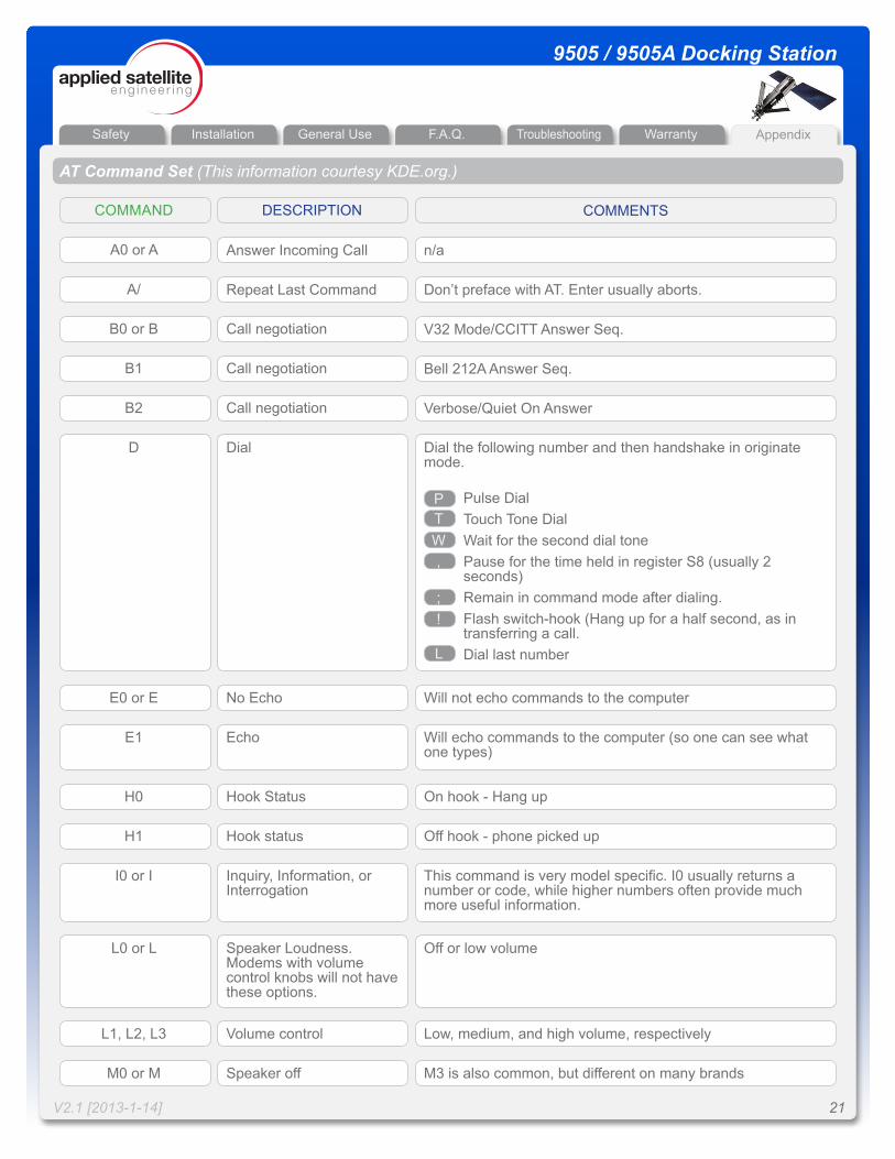
AT Command Set (This information courtesy KDE.org.)
COMMAND COMMENTS
Answer Incoming CallA0 or A n/a
Repeat Last CommandA/ Don’t preface with AT. Enter usually aborts.
Call negotiationB0 or B V32 Mode/CCITT Answer Seq.
Call negotiationB1 Bell 212A Answer Seq.
Call negotiationB2 Verbose/Quiet On Answer
DialD
No EchoE0 or E Will not echo commands to the computer
EchoE1 Will echo commands to the computer (so one can see what one types)
Hook StatusH0 On hook - Hang up
Hook statusH1 Off hook - phone picked up
Inquiry, Information, or Interrogation
I0 or I This command is very model specific. I0 usually returns a number or code, while higher numbers often provide much more useful information.
Speaker Loudness. Modems with volume control knobs will not have these options.
L0 or L Off or low volume
Dial the following number and then handshake in originate mode.
Pulse DialTouch Tone DialWait for the second dial tonePause for the time held in register S8 (usually 2 seconds)Remain in command mode after dialing.Flash switch-hook (Hang up for a half second, as in transferring a call.Dial last number
PTW,
;!
L
Volume controlL1, L2, L3 Low, medium, and high volume, respectively
Speaker offM0 or M M3 is also common, but different on many brands
Installation General Use F.A.Q. WarrantyTroubleshooting AppendixSafety
V2.1 [2013-1-14] 22
9505 / 9505A Docking Station
Appendix
DESCRIPTION
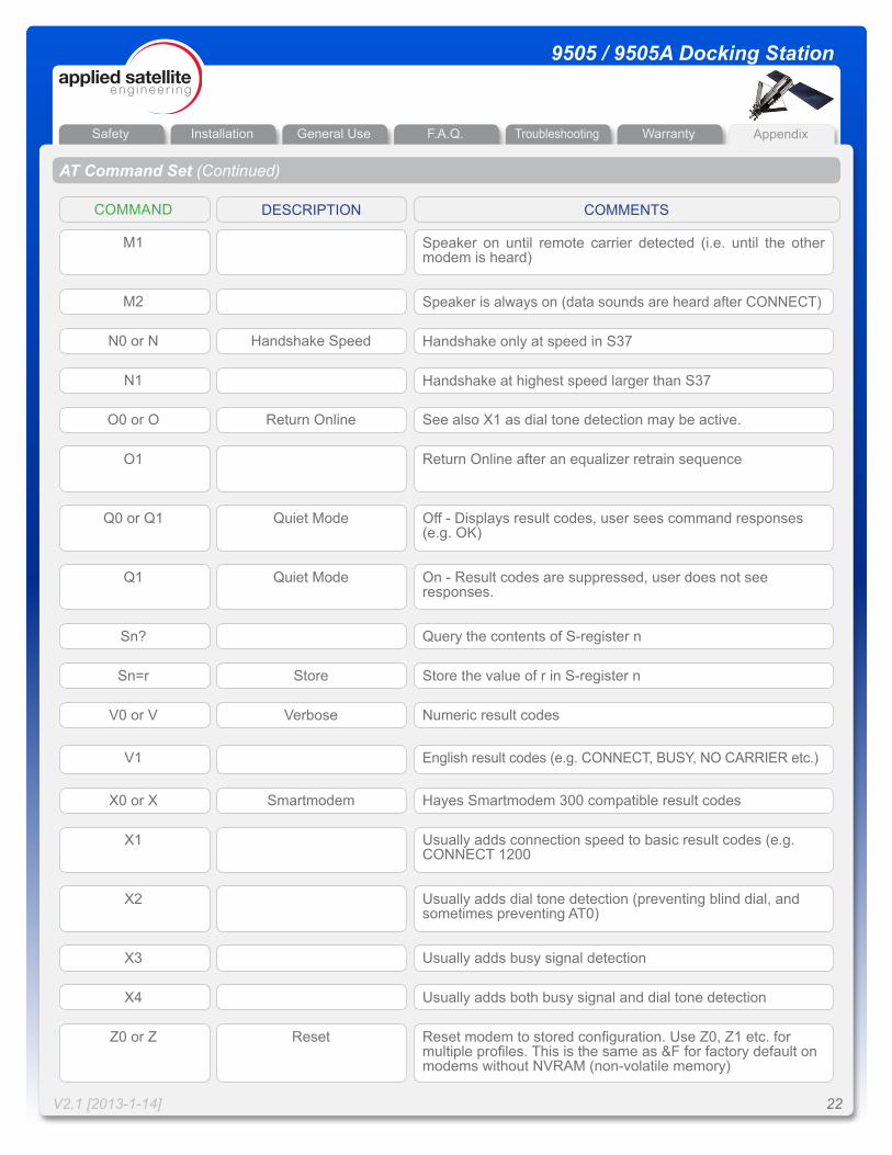
AT Command Set (Continued)
COMMAND COMMENTS
M1 Speaker on until remote carrier detected (i.e. until the other modem is heard)
M2 Speaker is always on (data sounds are heard after CONNECT)
Handshake SpeedN0 or N Handshake only at speed in S37
N1 Handshake at highest speed larger than S37
Return OnlineO0 or O See also X1 as dial tone detection may be active.
O1 Return Online after an equalizer retrain sequence
Quiet ModeQ0 or Q1 Off - Displays result codes, user sees command responses (e.g. OK)
Quiet ModeQ1 On - Result codes are suppressed, user does not see responses.
Sn? Query the contents of S-register n
StoreSn=r Store the value of r in S-register n
VerboseV0 or V Numeric result codes
V1 English result codes (e.g. CONNECT, BUSY, NO CARRIER etc.)
SmartmodemX0 or X Hayes Smartmodem 300 compatible result codes
X1 Usually adds connection speed to basic result codes (e.g. CONNECT 1200
X2 Usually adds dial tone detection (preventing blind dial, and sometimes preventing AT0)
X3 Usually adds busy signal detection
X4 Usually adds both busy signal and dial tone detection
ResetZ0 or Z Reset modem to stored configuration. Use Z0, Z1 etc. for multiple profiles. This is the same as &F for factory default on modems without NVRAM (non-volatile memory)
Installation General Use F.A.Q. WarrantyTroubleshooting AppendixSafety
V2.1 [2013-1-14] 23
9505 / 9505A Docking Station
Appendix
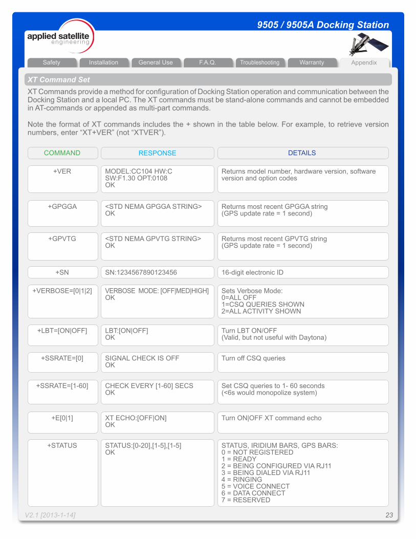
MODEL:CC104 HW:CSW:F1.30 OPT:0108OK
+VER Returns model number, hardware version, software version and option codes
<STD NEMA GPGGA STRING>OK
+GPGGA Returns most recent GPGGA string (GPS update rate = 1 second)
<STD NEMA GPVTG STRING>OK
+GPVTG Returns most recent GPVTG string (GPS update rate = 1 second)
VERBOSE MODE: [OFF|MED|HIGH]OK
+VERBOSE=[0|1|2] Sets Verbose Mode:0=ALL OFF1=CSQ QUERIES SHOWN2=ALL ACTIVITY SHOWN
LBT:[ON|OFF]OK
+LBT=[ON|OFF] Turn LBT ON/OFF(Valid, but not useful with Daytona)
SIGNAL CHECK IS OFFOK
+SSRATE=[0] Turn off CSQ queries
XT Command SetXT Commands provide a method for configuration of Docking Station operation and communication between the Docking Station and a local PC. The XT commands must be stand-alone commands and cannot be embedded in AT-commands or appended as multi-part commands.
Note the format of XT commands includes the + shown in the table below. For example, to retrieve version numbers, enter “XT+VER” (not “XTVER”).
RESPONSECOMMAND DETAILS
XT ECHO:[OFF|ON]OK
+E[0|1] Turn ON|OFF XT command echo
SN:1234567890123456+SN 16-digit electronic ID
CHECK EVERY [1-60] SECSOK
+SSRATE=[1-60] Set CSQ queries to 1- 60 seconds(<6s would monopolize system)
STATUS:[0-20],[1-5],[1-5]OK
+STATUS STATUS, IRIDIUM BARS, GPS BARS:0 = NOT REGISTERED1 = READY2 = BEING CONFIGURED VIA RJ113 = BEING DIALED VIA RJ114 = RINGING5 = VOICE CONNECT6 = DATA CONNECT7 = RESERVED
Installation General Use F.A.Q. WarrantyTroubleshooting AppendixSafety
V2.1 [2013-1-14] 24
9505 / 9505A Docking Station
Appendix
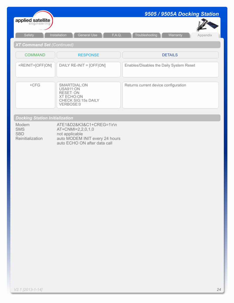
DAILY RE-INIT = [OFF|ON]+REINIT=[OFF|ON] Enables/Disables the Daily System Reset
SMARTDIAL:ONUSA911:ONRESET: ONXT ECHO:ONCHECK SIG:15s DAILYVERBOSE:0
+CFG Returns current device configuration
XT Command Set (Continued)
RESPONSECOMMAND DETAILS
Docking Station InitializationModem ATE1&D2&K3&C1+CREG=1\r\nSMS AT+CNMI=2,2,0,1,0SBD not applicableReinitialization auto MODEM INIT every 24 hours auto ECHO ON after data call