
9438 Low and high level dissolved oxygen monitor · 2015-07-13 · 5.2 Switch Familiarization ......
48
User Guide IM/9438 Rev. N 9438 Low and high level dissolved oxygen monitor
Transcript of 9438 Low and high level dissolved oxygen monitor · 2015-07-13 · 5.2 Switch Familiarization ......

User Guide IM/9438 Rev. N
9438Low and high level dissolved oxygen monitor

The CompanyWe are an established world force in the design and manufacture of measurement products for industrial process control, flow measurement, gas and liquid analysis and environmental applications.
As a part of ABB, a world leader in process automation technology, we offer customers application expertise, service and support worldwide.
We are committed to teamwork, high quality manufacturing, advanced technology and unrivalled service and support.
The quality, accuracy and performance of the Company’s products result from over 100 years experience, combined with a continuous program of innovative design and development to incorporate the latest technology.
EN ISO 9001:2008
Cert. No. Q 05907
EN 29001 (ISO 9001)
Lenno, Italy – Cert. No. 9/90A
Stonehouse, U.K.
����
Electrical SafetyThis equipment complies with the requirements of CEI/IEC 61010-1:2001-2 'Safety Requirements for Electrical Equipment for Measurement, Control and Laboratory Use'. If the equipment is used in a manner NOT specified by the Company, the protection provided by the equipment may be impaired.
SymbolsOne or more of the following symbols may appear on the equipment labelling:
Warning – Refer to the manual for instructions Direct current supply only
Caution – Risk of electric shock Alternating current supply only
Protective earth (ground) terminal Both direct and alternating current supply
Earth (ground) terminalThe equipment is protected through double insulation
Information in this manual is intended only to assist our customers in the efficient operation of our equipment. Use of this manual for any other purpose is specifically prohibited and its contents are not to be reproduced in full or part without prior approval of the Technical Publications Department.
Health and Safety
To ensure that our products are safe and without risk to health, the following points must be noted:
1. The relevant sections of these instructions must be read carefully before proceeding.
2. Warning labels on containers and packages must be observed.
3. Installation, operation, maintenance and servicing must only be carried out by suitably trained personnel and in accordance with the information given.
4. Normal safety precautions must be taken to avoid the possibility of an accident occurring when operating in conditions of high pressure and/or temperature.
5. Chemicals must be stored away from heat, protected from temperature extremes and powders kept dry. Normal safe handling procedures must be used.
6. When disposing of chemicals ensure that no two chemicals are mixed.
Safety advice concerning the use of the equipment described in this manual or any relevant hazard data sheets (where applicable) may be obtained from the Company address on the back cover, together with servicing and spares information.

9438Low and high level dissolved oxygen monitor Contents
IM/9438 Rev. N 1
Contents
1 INTRODUCTION ..............................................................2
2 MECHANICAL INSTALLATION .......................................32.1 Siting Requirements .................................................3
2.1.1 Instruments ...................................................32.1.2 Dissolved Oxygen Flowcell ............................3
2.2 Mounting the Instrument ..........................................32.2.1 Wall-mounted Instrument ..............................32.2.2 Panel-mounted Instrument ...........................4
2.3 Installing the Dissolved Oxygen Flowcell ...................52.3.1 Flowcell Dimensions (Overall) ........................52.3.2 Enclosure Dimensions (Optional) ...................52.3.3 Connecting the Sample Lines .......................5
3 ELECTRICAL CONNECTIONS ........................................63.1 Access to Terminals .................................................6
3.1.1 Wall-mounted Instruments ............................63.1.2 Panel-mounted Instruments ..........................6
3.2 Connections, General ...............................................73.2.1 Relay Contact Protection
and Interference Suppression .......................73.2.2 System Wiring Schematic .............................8
3.3 Wall-mounted Instrument Connections ....................83.4 Panel-mounted Instrument Connections ..................93.5 Selecting the Mains Voltage ...................................10
3.5.1 Wall-mounted Instrument ...........................103.5.2 Panel-mounted Instrument .........................10
3.6 Flowcell Solenoid Valve Connections ......................11
4 SETTING UP ..................................................................124.1 Fitting the Dissolved Oxygen Sensor ......................124.2 Connecting the Flowcell .........................................144.3 Checking Sample Flow ..........................................15
5 CONTROLS AND DISPLAYS ........................................165.1 Displays .................................................................165.2 Switch Familiarization .............................................16
6 START UP AND OPERATION .......................................176.1 Instrument Start-up ................................................186.2 Operation – Dissolved Oxygen Measurement Mode 18
6.2.1 Operation Page ..........................................196.2.2 Calibration Page .........................................20
7 PROGRAMMING AND ELECTRICAL CALIBRATION .. 217.1 Access to Secure Parameters ............................... 217.2 Language Page ..................................................... 217.3 Set Up Parameters Page ....................................... 227.4 Set Up Alarm Page ................................................ 237.5 Set Up Retransmission Page ................................. 257.6 Electrical Calibration .............................................. 28
7.6.1 Equipment Required .................................. 287.6.2 Preparation ................................................ 28
7.7 Factory Settings Page ........................................... 29
8 MAINTENANCE ............................................................. 328.1 Introduction ........................................................... 328.2 Cleaning/Changing the Sensor .............................. 32
8.2.1 Cleaning ..................................................... 328.2.2 Changing the Sensor .................................. 33
9 SIMPLE FAULT FINDING ............................................. 349.1 Diagnostic Messages ............................................. 349.2 Low Sensor Efficiency/Slow
Sensor Cal. or No Response to D.O. Changes ...... 359.3 Checking the Temperature Input ............................ 359.4 High Sample Readings .......................................... 35
10 SPECIFICATION ........................................................... 36
11 SPARES ........................................................................ 3811.1 Strategic Spares .................................................... 3811.2 Replacement Spares ............................................. 38
Appendix A 9438 080 24 V DC POWER SUPPLY UNIT (OPTIONAL) ................................ 40
A.1 Description ............................................................ 40A.2 PSU Dimensions .................................................... 40A.3 Accessing PSU Terminals ...................................... 40A.4 PSU Connection .................................................... 41A.5 Wiring Schematic .................................................. 41A.6 Specification .......................................................... 41
Appendix B CALIBRATION DIAGNOSTICS ...................... 42B.1 During Calibration .................................................. 42B.2 Low Sensor Efficiency ........................................... 43
Notes ................................................................................ 44
9438Low and high level dissolved oxygen monitor 1 INTRODUCTION
2 IM/9438 Rev. N
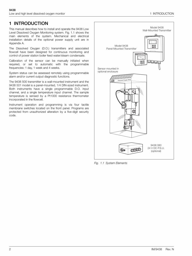
1 INTRODUCTIONThis manual describes how to install and operate the 9438 LowLevel Dissolved Oxygen Monitoring system. Fig. 1.1 shows themain elements of the system. Mechanical and electricalinstallation details of the optional power supply unit are inAppendix A.
The Dissolved Oxygen (D.O.) transmitters and associatedflowcell have been designed for continuous monitoring andcontrol of power station boiler feed water/steam condensate.
Calibration of the sensor can be manually initiated whenrequired, or set to automatic with the programmablefrequencies: 1 day, 1 week and 4 weeks.
System status can be assessed remotely using programmablealarm and/or current output diagnostic functions.
The 9438 500 transmitter is a wall-mounted instrument and the9438 501 model is a panel-mounted, 1/4 DIN-sized instrument.Both instruments have a single programmable D.O. inputchannel, and a single temperature input channel. The sampletemperature is sensed by a Pt1000 resistance thermometerincorporated in the flowcell.
Instrument operation and programming is via four tactilemembrane switches located on the front panel. Programs areprotected from unauthorized alteration by a five-digit securitycode.
Fig. 1.1 System Elements
��������� �������������� ��������
�������������������
�� ���� �!
���������� �������
������������������ ���� ����"������
��������# ������������� ��������
�������
�������
���� ������ �
$%
$�
9438Low and high level dissolved oxygen monitor 2 MECHANICAL INSTALLATION
IM/9438 Rev. N 3
2 MECHANICAL INSTALLATION2.1 Siting Requirements
2.1.1 Instruments
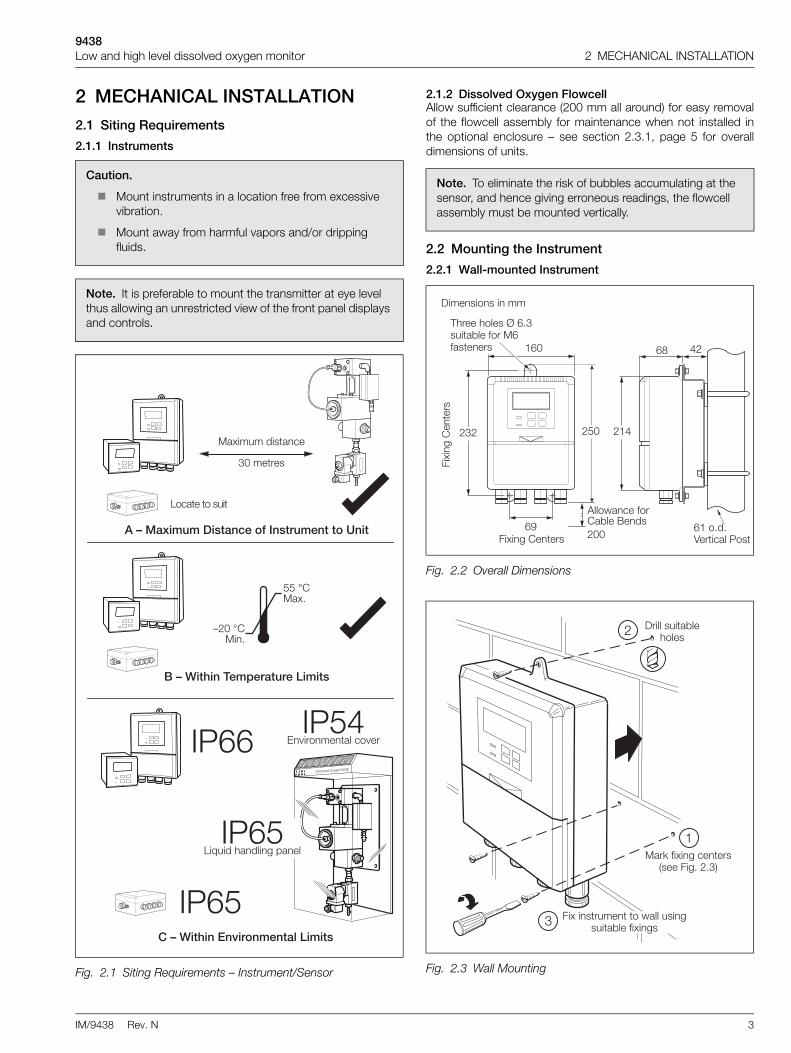
2.1.2 Dissolved Oxygen FlowcellAllow sufficient clearance (200 mm all around) for easy removalof the flowcell assembly for maintenance when not installed inthe optional enclosure – see section 2.3.1, page 5 for overalldimensions of units.
2.2 Mounting the Instrument
2.2.1 Wall-mounted Instrument
Caution.
Mount instruments in a location free from excessive vibration.
Mount away from harmful vapors and/or dripping fluids.
Note. It is preferable to mount the transmitter at eye level thus allowing an unrestricted view of the front panel displays and controls.
Fig. 2.1 Siting Requirements – Instrument/Sensor
� &��������� �"�
��������
������������ �������������
''�(�� &�
)���(�����
�������������� ��� ��������
�������������������������� �������� ��
*�" ����������
+�,,
+�,'
+�'-�.�������� ��"�.��
������.���/&01�����
+�,'*�2����3 �����1� ���
Note. To eliminate the risk of bubbles accumulating at the sensor, and hence giving erroneous readings, the flowcell assembly must be mounted vertically.
Fig. 2.2 Overall Dimensions
Fig. 2.3 Wall Mounting
,� �
4�&��1��������
%,�
,�4�&��1��������
$���5 �"��6��� 7���8�������
,%����������" ������
�%��
�3����3�����9�,����� 7���6����,6 �������
����������������
�'�
� �:�6�&��1�"�����������4�1����!
���������� 7��3����
4�&���������������5 �������1���� 7���6�&��1�

9438Low and high level dissolved oxygen monitor 2 MECHANICAL INSTALLATION
4 IM/9438 Rev. N
2.2.2 Panel-mounted Instrument
Fig. 2.4 Pipe Mounting
���������;�<�7�������� � �
��������� � �����.���;�<�7����
��"������ �������������������1� � ��
��"���� � ���
%
�
Fig. 2.5 Overall Dimensions
%�%%�
� �����������
�,
�,
��������
��������
����������������
Fig. 2.6 Panel Mounting
���� �3��������3�� ���������4�1����'�6�������������!�+������������ 0�7��"������� ":�������+=��'�
+�������3�������������������3� ����"�������
>�6����3�� ����"� � ������3��" ��?��������1�3 ���3�� ����"� � � �"3���� �����" ���"����"��0�����3���������
��"�����3�������������70���13�����1��3� ����"� � ���� ����1��"��5��
*�������3����� ����1��"��5���� "3� ����"� � �
>���.���3�� ����"� � � �� �"3����6�����3�������������" ���
'
,
%
�

9438Low and high level dissolved oxygen monitor 2 MECHANICAL INSTALLATION
IM/9438 Rev. N 5
2.3 Installing the Dissolved Oxygen Flowcell
2.3.1 Flowcell Dimensions (Overall)
2.3.2 Enclosure Dimensions (Optional)
2.3.3 Connecting the Sample LinesMount the flowcell vertically (with or without the enclosure) asshown in Fig. 2.7 and Fig. 2.8. Connect the sample inlet andoutlet tubes as shown in Fig. 2.9.
Fig. 2.7 Flowcell Dimensions
Fig. 2.8 Enclosure Dimensions
%��
�'
%@'
%��
%%, ��&�� ���0
%�
%�
%� ��&�� ���0
9�'�'6����'�6 ���������6���� ��������
�����������������
���������� �������
9���'4������6 ���������6���� ��������
����������������
�' �'
�'
%,������ "����2������7���5������� ���?���� ���5�6����3��� ����1��6��3�
� ���� ����.�������� ��"�.��
%,�
�
���
�'
��"�����3����"���������� .����" �����6 "������1��3��6���6�&��1�3����� ������� 7���"��5�A7����
Note.
The sample flowrate must be between 100 and 400 ml min–1.
The Company recommends that stainless steel tubing is used for sample inlet lines.
All sample drains should be kept as short as possible and be vertical to allow the sample to drain freely.
Fig. 2.9 Connecting the Sample Lines
Note. Drain tubes must be straight and vertical to allow the sample to flow freely.
4��5�B �1����A���!
=������� �.��������
6��5�� ��!
��������
� � ��/�����
���������� �� ���� �.�
� � ���� ��
������� ����%�����������77�����7��1
������� ����%�����������77�����7��1
%���� &����
�� ���)����!���
� � ��/�����
� � ���������.� �3����66�. �.���6��2������
� � ����� ��������1 ���� ��"�" ��7� ����

9438Low and high level dissolved oxygen monitor 3 ELECTRICAL CONNECTIONS
6 IM/9438 Rev. N
3 ELECTRICAL CONNECTIONS
3.1 Access to Terminals
3.1.1 Wall-mounted Instruments 3.1.2 Panel-mounted Instruments
Warning.
Before making any connections, ensure that the power supply, any high voltage-operated control circuits and high common mode voltage are switched off.
Although certain instruments are fitted with internal fuse protection, a suitably rated external protection device, e.g. fuse or miniature circuit breaker (m.c.b.), must also be fitted by the installer.
Fig. 3.1 Access to Terminals – Wall-mounted Instrument
�
�
�
�
�
- ��3������
�������5�
�����������13��0����� ������ ��
�������66
>���.� ����"����"�.��
�� ":��" ��.��"��5�
Fig. 3.2 Access to Terminals – Panel-mounted Instrument (Rear View)
>���.������� �� ����"�����"�.��
>���.�� ����"�.��
� �����.��
- ��3�����
%�

9438Low and high level dissolved oxygen monitor 3 ELECTRICAL CONNECTIONS
IM/9438 Rev. N 7
3.2 Connections, General
3.2.1 Relay Contact Protection and Interference SuppressionIf the relays are used to switch loads on and off, the relay contacts can become eroded due to arcing. Arcing also generates radiofrequency interference (RFI) which can result in instrument malfunction and incorrect readings. To minimize the effects of RFI, arcsuppression components are required; resistor/capacitor networks for AC applications or diodes for DC applications. Thesecomponents can be connected either across the load or directly across the relay contacts. On 4600 Series instruments the RFIcomponents must be fitted to the relay terminal block along with the supply and load wires – see Fig. 3.3.
For AC applications the value of the resistor/capacitor network depends on the load current and inductance that is switched. Initially,fit a 100R/0.022 µF RC suppressor unit (part no. B9303) as shown in Fig. 3.3A. If the instrument malfunctions (incorrect readings) orresets (display shows 88888) the value of the RC network is too low for suppression – an alternative value must be used. If the correctvalue cannot be obtained, contact the manufacturer of the switched device for details on the RC unit required.
For DC applications fit a diode as shown in Fig. 3.3B. For general applications use an IN5406 type (600 V peak inverse voltage at 3 A – part no. B7363).
Note.
Earthing (grounding) – stud terminals are fitted to the transmitter case for bus-bar earth (ground) connection – see Fig. 3.1 or Fig. 3.2.
Cable lengths – the cable length between the flowcell and the electronics unit is provided as ordered, and suitably terminated at both ends.
Cable routing – always route the signal cable and mains-carrying/relay cables separately, ideally in earthed metal conduit.
Ensure that the cables enter the transmitter through the glands nearest the appropriate screw terminals and are short and direct. Do not tuck excess cable into the terminal compartment.
Cable glands & conduit fittings – ensure a moisture-tight fit when using cable glands, conduit fittings and blanking plugs/bungs (M20 holes). The M16 glands ready-fitted to wall-mounted instruments accept cable of between 4 and 7 mm diameter.
Alarm Relay – the relay contacts are voltage-free and must be appropriately connected in series with the power supply and the alarm/control device which they are to actuate. Ensure that the contact rating is not exceeded. Refer also to Section 3.2.1 for relay contact protection details when the relays are to be used for switching loads.
Retransmission output – do not exceed the maximum load specification for the selected current retransmission range – see section 7, page 21.
Since the retransmission output is isolated the –ve terminal must be connected to earth (ground) if connecting to the isolated input of another device.
Note. For reliable switching the minimum voltage must be greater than 12 V and the minimum current greater than 100 mA.
Fig. 3.3 Relay Contact Protection
=� � =/
-&���� ������ �0
C )
���� ������
*� �
�����
=� � =/
-&���� �$���� �0
* =
>�� 0����� "��
�>
*� �
������������������ ������������������

9438Low and high level dissolved oxygen monitor 3 ELECTRICAL CONNECTIONS
8 IM/9438 Rev. N
3.2.2 System Wiring SchematicThe wiring of a single solenoid/sensor system from auser-supplied 24 V DC supply is shown in Fig. 3.4.
If the 9438 080 power supply unit is employed, refer toAppendix A for wiring details.
3.3 Wall-mounted Instrument Connections
Note. Refer to Fig. 3.1 for access to terminals.
Fig. 3.4 Wiring Schematic(see Appendix A for wiring using optional PSU)
Caution. Slacken terminal screws fully before making connections.
����� ��������
������������������ �0
>�� 0������=/
���������� �.�
���������. �.�� �5�����6���������� ����������������"�
C.�
).�
Fig. 3.5 Wall-mounted Instrument Connections
Warning. The power supply earth (ground) must be connected to ensure safety to personnel, reduction of the effects of RFI and correct operation of the power supply interference filter.
"�#� $����%
&�� �������� &���%�'&���%�(
$� ���
"�#� $����%
&�� ��) &���%�'&���%�(
' ( * + , - . / � ! �
$� ���0��������12
' ( *
+ , -
' ( *
+ , -
%�',
'
))))))
))
>&C>&)�&C�&)��
>��� ���/�� ��
>�� 0�
%�',
)))))
=��=/�=/
>�� 0�%
��������. �.�� ��7� ����>�� 0
� ������ �0
=*
))
=���� �*���
) - ��3
/�� ��>���A>��'
- ��3����������" ��!�)����4�1���%
=��=/
=��� ��0�������������=��� ��0�/ ��
D
D
�����(�����'
%
))
C.���>��!).���8� ":!8� ��
��/��������
- ��3����������" ��!)�����4�1���%
�����(�����'
��%������ �� �������� ��� ���
',
@
))
)
#3���B����*��:
/
>��� �����/�� �����6�6�����!
�.�C.�

9438Low and high level dissolved oxygen monitor 3 ELECTRICAL CONNECTIONS
IM/9438 Rev. N 9
3.4 Panel-mounted Instrument Connections
Note. Refer to Fig. 3.2 for Access to Terminals.
Caution. Slacken terminal screws fully before making connections.
Fig. 3.6 Panel-mounted Instrument Connections
Warning. The power supply earth (ground) must be connected to ensure safety to personnel, reduction of the effects of RFI and correct operation of the power supply interference filter.
C)
=��� ��0�������������
=��� ��0�/ ��
������=��� ��0�/ ��
=���� �*�.�
- ��3
���
>�� 0�%
���������� �.�� ��7� ����
>�� 0
������
����
������!�
����
� ������ �0
>��� ���������/�� ��
��>&)>&C�&)�&C*��:B����#3���
).���8� ":!
C.���>��!
���
>���A>��'���� ��+����6 "���6�6�����!
��/��������
������!����
������!��������
- ��3�����
- ��3����������" ��!
- ��3����������" ��!
��%������ �� ����"�� ��� ���
8� ��
>��� ����/�� �����6�6�����!
).�C.�
'
9438Low and high level dissolved oxygen monitor 3 ELECTRICAL CONNECTIONS
10 IM/9438 Rev. N
3.5 Selecting the Mains Voltage
3.5.1 Wall-mounted Instrument 3.5.2 Panel-mounted Instrument
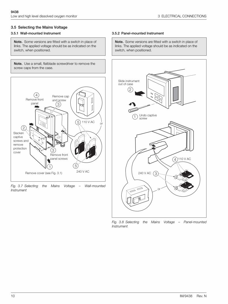
Note. Some versions are fitted with a switch in place of links. The applied voltage should be as indicated on the switch, when positioned.
Note. Use a small, flatblade screwdriver to remove the screw caps from the case.
Fig. 3.7 Selecting the Mains Voltage – Wall-mountedInstrument
>���.��"�.��������4�1���%!
>���.��6���� �����"��5�
>���.��6���� ���
>���.��" ����"��5
�� ":��" ��.��"��5�� ������.� ����"����"�.��
�����$�
%%����$�
���
��
%
'�
'
Note. Some versions are fitted with a switch in place of links. The applied voltage should be as indicated on the switch, when positioned.
Fig. 3.8 Selecting the Mains Voltage – Panel-mountedInstrument
�����" ��.��"��5
���������������������6�" ��
�����$�
%%����$�
���
��
%
�
9438Low and high level dissolved oxygen monitor 3 ELECTRICAL CONNECTIONS
IM/9438 Rev. N 11
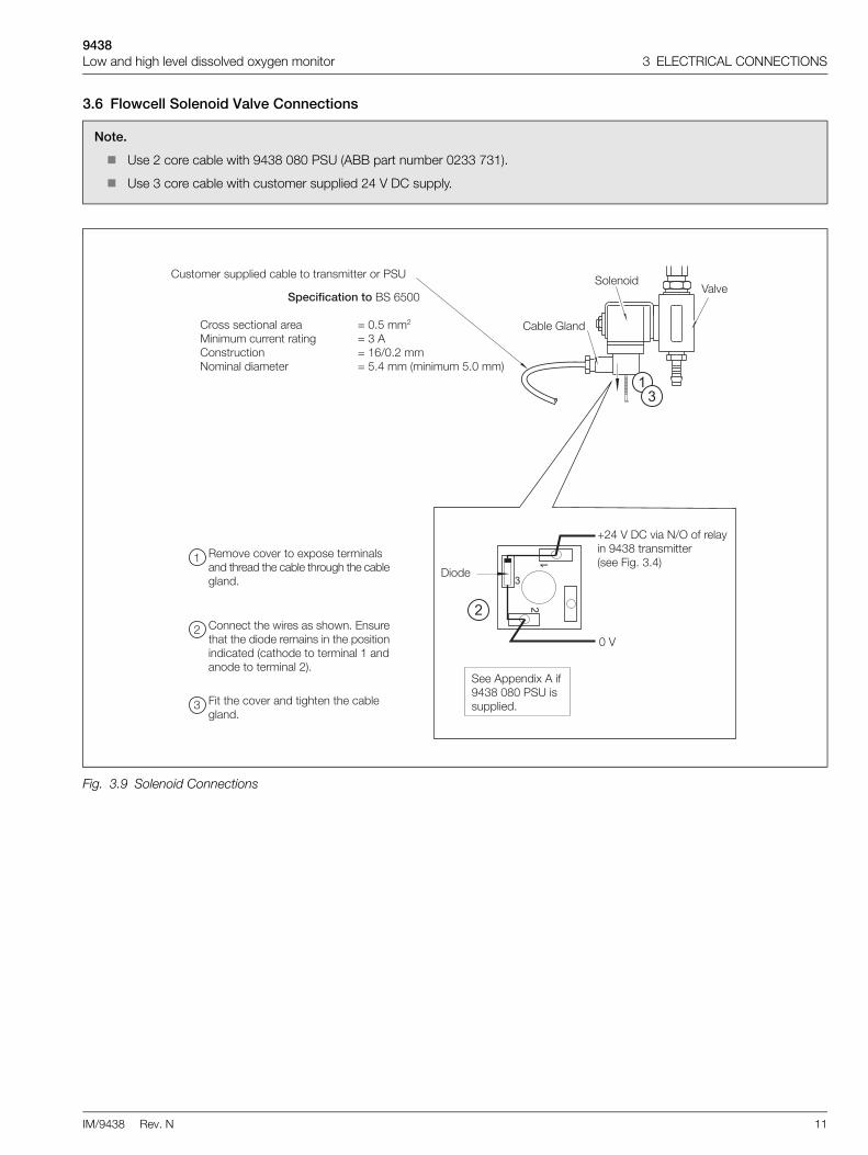
3.6 Flowcell Solenoid Valve Connections
Note.
Use 2 core cable with 9438 080 PSU (ABB part number 0233 731).
Use 3 core cable with customer supplied 24 V DC supply.
Fig. 3.9 Solenoid Connections
$���������������8��,'��
��������"���� �� �� D���'����
��������"�������� ���1 D��$�������"���� D�%,A������=���� ���� ����� D�'��������������'�����!
>���.��"�.�������& ���������� �� ����3�� ���3��" 7����3���13��3��" 7��1� ���
�����"���3��5����� ���3�5���-������3 ���3����������� ��������3�� �����������" �����" �3������������� ��%� �� �������������� ���!�
4����3��"�.��� �����13�����3��" 7��1� ���
��������� �.�
�
�
�
C�������.� �=A/��6���� 0�������� �������������4�1���!
���
� 7���B� ��
�����
����$ ����&�$��6��������������� �����
����������� �����" 7�������� ���������������
�
��
�
%

9438Low and high level dissolved oxygen monitor 4 SETTING UP
12 IM/9438 Rev. N
4 SETTING UP4.1 Fitting the Dissolved Oxygen Sensor
To fit the dissolved oxygen sensor:
a Remove the top from the oxygen sensor container.
b Unscrew the protective cap from the rear of the oxygen sensor.
Referring to Fig. 4.1:
c Fit the smaller (7/8 in. ID) of the 2 O-rings.
Locate the sensor on the connector body and tighten up the connector nut onto the sensor.
If replacing the sensor, fit new O-ring (supplied).
d Slide the thrust washer over the connector body.
e Insert the complete assembly into the flowcell ensuring the larger of the 2 O-rings is fitted (or replaced, if fitting a new sensor).
f Use the clamping screw to secure the assembly. Screw in firmly using finger pressure only.
Caution.
Only install the oxygen sensor immediately prior to use, otherwise leave it stored in its protective container. The sensor has a limited shelf life and should NOT be stored longer than about 6 months. Store under cool conditions.
Take special care to line up the two pins in the oxygen sensor with their respective sockets before making the connection and tightening.
Take care not to damage the delicate membrane on the end of the oxygen sensor.
Ensure that the mating surfaces (carrying the electrical connection) of the oxygen sensor and connector body are clean and completely dry.
Caution. Do not overtighten the clamping screw.

9438Low and high level dissolved oxygen monitor 4 SETTING UP
IM/9438 Rev. N 13
Optional enclosure not shown for clarity
Fig. 4.1 Fitting the Dissolved Oxygen Sensor
Flowcell
O-ring (7/8 in. ID)
OxygenSensor
O-ring (3/4 in. ID)5
3
Protective Cover
End Cap
O-ring
4
6
ConnectorBody
ClampingScrew
ThrustWasher
ConnectorNut

9438Low and high level dissolved oxygen monitor 4 SETTING UP
14 IM/9438 Rev. N
4.2 Connecting the Flowcell
Note.
The plug is a latching type to prevent it's accidental removal. To remove, hold the plug at its widest point and pull out.
The plug is protected against spillage and corrosion by a sleeve which slides over it.
Fig. 4.2 Electrical Connections at the Flowcell
*����� ��3������� ���� �� ��3��3�� ��1����6����0�������3����":��1����1���1 1���
���3��3���������"����"������6����0� �����13����/=-���>="��":5����

9438Low and high level dissolved oxygen monitor 4 SETTING UP
IM/9438 Rev. N 15
4.3 Checking Sample FlowCheck that the sample flows correctly in both normal operation and during a calibration or thermal overload. To simulate a calibrationmanually, open the valve – see section 6.2.1, page 19 Operating Page. Carefully remove the dissolved oxygen sensor and check thatthe flowcell is empty. If sample still flows, check that the installation complies with see section 2.3.3, page 5.
Fig. 4.3 Sample Flow Schematic
4��5������1����� �� �� ����
��������/ �� ���� �.��)�������
4��5>�1�� ���1� �.�
������
4��5�+���" ���
�� ��
� � ���+�
4��5������1�" ��7� ��������3��� ���.���� ��"��������
��������/ �� ���� �.��)�/ ��
� � ��+�
�� ��

9438Low and high level dissolved oxygen monitor 5 CONTROLS AND DISPLAYS
16 IM/9438 Rev. N
5 CONTROLS AND DISPLAYS5.1 DisplaysThe display comprises a 5-digit, 7-segment digital upper displayline and a 16-character dot-matrix lower display line. The upperdisplay line shows numerical values of dissolved oxygenconcentration, temperature, alarm set points or programmableparameters. The lower display line shows the associated unitsor programming information.
5.2 Switch Familiarization
Fig. 5.1 Location of Controls and Displays
$� ��*-��
� ����� � 0�*���
*�5����� � 0�*���
���7� ����5��"3��
Fig. 5.2 Membrane Switch Functions
�����1����3����!����"�3�
"#$#%�&�$�"#$#%�&�$�"#$#%�&�$�"#$#%�&�$�
"�3��'"#$#%�&�$�"#$#%�&�$�"#$#%�&�$�
"�3��(
$�. �"������&�� 1�
4���� E����0�6� � ������
��
��������3����#���"� ����� �
�����14����3��1�$�� �3���"� ����� �5����
=�5�. ������ ���� ��" ��0�������
"#$#%�&�$'#�(� $�E���
����$������3��1�$�� �3���"� ����� ������
"#$#%�&�$)*+
����"�
"#$#%�&�$�
"#$#%�&�$�"#$#%�&�$�
"�3��6
"#$#%�&�$�
$�. �"������&�� � �����
��
=�5�. ������ ���� ��" ��0���������

9438Low and high level dissolved oxygen monitor 6 START UP AND OPERATION
IM/9438 Rev. N 17
6 START UP AND OPERATION
Note. The values shown on the pages in this illustration are the factory default values.
Fig. 6.1 Overall Programming Chart
*��� �
����������� �
��
��
�
������
��
��
�������������
����
����
�
�������������
��
��
�
�����������
�
��
��
�
�����
��
��
���������� !"
��
��
��������� #"
��
��
�$%�&���'���
��
��
�
��������
����"�
�������(
����"
��
�������)�*��$�
����
����
�
�$%�&���'����
��
��
�
7���� %�$����3��"�3�
��"�����@�,
�*�*
F+, +
��� �
�����������
�
��
��
�
����������+���
��
��-..���/����
��
��
�
.��&&���
��0+
��
������1
����
����*-���&�(�"
��
��
�
��&�*-���&�+, +
�+,�
���
��
��
���-.����/
��
��
�
0�+2���+, +
� ��
��
��
����)����0�,��
0�+2
��3
���1������&
����
��
�44
��
��
�
��3��
�+, +
��
������)*��$�
����
����
�
��������*��$�
����
����
�
��-.�����
��
��
�
��-.����� �
��
��
�
��
����'����+, +
���
��'�����+, +
����
����������5
�
�������������5
��
��
���'�1��67(!
!7(!
!7�!
��'*��+
8�7������
������
��
��
�
���+��&��)&��
�
��-.�����
(
��
��
�
���*����
&
��
����/*����
&
��
����*����
&
��
��'*��+
8�7������
������
��
��
�
��'�,.����
�*�*
��
��
�
��
����'����+, +
��
���
��'�����+, +
��
��
��
���'�1��67(!
!7(!
!7�!
8��*��� �
8��*��� �
*��� �
����
����������5
�
�������������5
���*����
&
��
����/*����
&
��
����*����
&
��
��&�������&*�5"
��
����)���44
69�� &
�9��
���1
��
��
�
��������������"
��
� �
��&���,.�F�
!
��
��
�
��&���44�����
��
��
�
0�+2��F+, +
� � �
��3��F+, +
� �
8�� �����"�3�
��"�����,���%
����9 �����"�3�
��"�����,����
���+��&��)&��
�
$��� ��&�� ���������"�3�
��"�����@�'
$��� ��"� ����� ��"�3�
��"�����@�
$��� ����� ��"�3�
��"�����@�
��-��������
��
��
�
����������$��� ��"� ����� �
��"�����@�%
$��� ��"� ����� �
� ���0
��
��
�
��3��3��"�3�
��"�����@��
����:��;�
�
��
��
��
�
�������� �>��� ����
+6�=/�>��� ����
��&�����* �
��
��
��
�
� �����*
��
��
�
��
��
�����-&����$�
���*������$
��
��
�
��
��
���&���44�����
��)�;��1.����$
�
��
��
��
���3��&�����*
/ �� ���1� � �������
$. �� 7������0�53������
���� ���
���������� ������6������
��"���� � �������

9438Low and high level dissolved oxygen monitor 6 START UP AND OPERATION
18 IM/9438 Rev. N
6.1 Instrument Start-upEnsure all electrical connections have been made and switch on the power supply. If the instrument is being commissioned for thefirst time, calibration and programming of parameters is required.The overall operating and programming chart is shown in Fig. 6.1.
6.2 Operation – Dissolved Oxygen Measurement ModeOperation in the Dissolved Oxygen measurement mode comprises an Operating Page and a Calibration Page. The Operating Page is ageneral use page in which parameters are viewed only and cannot be altered. To alter or program a parameter, refer to theprogramming pages in Section 7. The Calibration Page allows a calibration to be carried out. A 5-digit calibration code is used toprevent unauthorized access to the sensor calibration page. The value is preset at 00000 to allow access during commissioning, butshould be altered to a unique value, known only to authorized operators, in the Set Up Alarm page – see section 7.2, page 21.
9438Low and high level dissolved oxygen monitor 6 START UP AND OPERATION
IM/9438 Rev. N 19
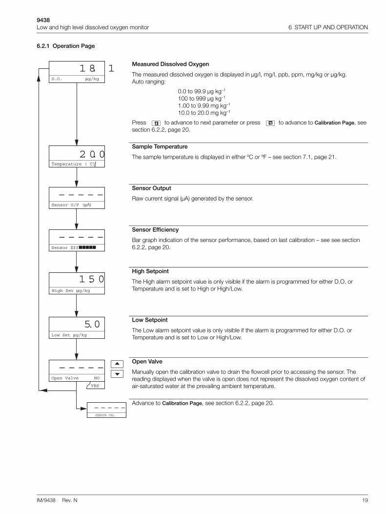
6.2.1 Operation Page
Measured Dissolved Oxygen
The measured dissolved oxygen is displayed in µg/l, mg/l, ppb, ppm, mg/kg or µg/kg.Auto ranging:
0.0 to 99.9 µg kg–1
100 to 999 µg kg–1
1.00 to 9.99 mg kg–1
10.0 to 20.0 mg kg–1
Press to advance to next parameter or press to advance to Calibration Page, see section 6.2.2, page 20.
Sample Temperature
The sample temperature is displayed in either ºC or ºF – see section 7.1, page 21.
Sensor Output
Raw current signal (µA) generated by the sensor.
Sensor Efficiency
Bar graph indication of the sensor performance, based on last calibration – see see section 6.2.2, page 20.
High Setpoint
The High alarm setpoint value is only visible if the alarm is programmed for either D.O. or Temperature and is set to High or High/Low.
Low Setpoint
The Low alarm setpoint value is only visible if the alarm is programmed for either D.O. or Temperature and is set to Low or High/Low.
Open Valve
Manually open the calibration valve to drain the flowcell prior to accessing the sensor. The reading displayed when the valve is open does not represent the dissolved oxygen content of air-saturated water at the prevailing ambient temperature.
Advance to Calibration Page, see section 6.2.2, page 20.
D.O. μg/kg
Temperature ( C)
SENSOR CAL.
– – – – –
1 8 1
2 0 0.
High Set μg/kg
1 5 0
Open Valve NO
YES
.
¡
.
Sensor Eff
– – – – –
Low Set μg/kg
5 0.
– – – – –
Sensor O/P (μA)
– – – – –
9438Low and high level dissolved oxygen monitor 6 START UP AND OPERATION
20 IM/9438 Rev. N
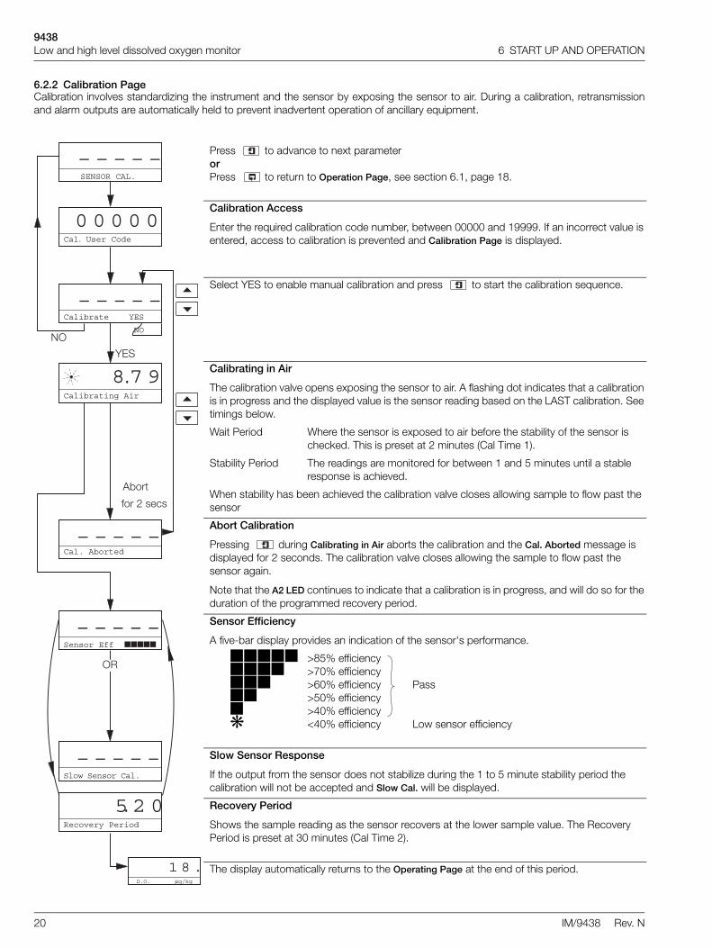
6.2.2 Calibration PageCalibration involves standardizing the instrument and the sensor by exposing the sensor to air. During a calibration, retransmissionand alarm outputs are automatically held to prevent inadvertent operation of ancillary equipment.
Press to advance to next parameterorPress to return to Operation Page, see section 6.1, page 18.
Calibration Access
Enter the required calibration code number, between 00000 and 19999. If an incorrect value is entered, access to calibration is prevented and Calibration Page is displayed.
Select YES to enable manual calibration and press to start the calibration sequence.
Calibrating in Air
The calibration valve opens exposing the sensor to air. A flashing dot indicates that a calibration is in progress and the displayed value is the sensor reading based on the LAST calibration. See timings below.
Wait Period Where the sensor is exposed to air before the stability of the sensor is checked. This is preset at 2 minutes (Cal Time 1).
Stability Period The readings are monitored for between 1 and 5 minutes until a stable response is achieved.
When stability has been achieved the calibration valve closes allowing sample to flow past the sensor
Abort Calibration
Pressing during Calibrating in Air aborts the calibration and the Cal. Aborted message is displayed for 2 seconds. The calibration valve closes allowing the sample to flow past the sensor again.
Note that the A2 LED continues to indicate that a calibration is in progress, and will do so for the duration of the programmed recovery period.
Sensor Efficiency
A five-bar display provides an indication of the sensor's performance.
>85% efficiency >70% efficiency>60% efficiency>50% efficiency>40% efficiency<40% efficiency
Pass
Low sensor efficiency
Slow Sensor Response
If the output from the sensor does not stabilize during the 1 to 5 minute stability period the calibration will not be accepted and Slow Cal. will be displayed.
Recovery Period
Shows the sample reading as the sensor recovers at the lower sample value. The Recovery Period is preset at 30 minutes (Cal Time 2).
The display automatically returns to the Operating Page at the end of this period.
YES
NO
Abort
for 2 secs
Calibrating Air
8 7 9.
SENSOR CAL.
– – – – –
0 0 0 0 0Cal. User Code
Cal. Aborted
– – – – –
– – – – –Sensor Eff
Recovery Period
5 2 0.
D.O. μg/kg
1 8 .
Calibrate YES
NO
– – – – –
– – – – –Slow Sensor Cal.
OR

9438Low and high level dissolved oxygen monitor 7 PROGRAMMING AND ELECTRICAL CALIBRATION
IM/9438 Rev. N 21
7 PROGRAMMING AND ELECTRICAL CALIBRATION7.1 Access to Secure ParametersA 5-digit security code is used to prevent tampering with the secure parameters.
7.2 Language Page
Security Code
Enter the required code number between 00000 and 19999 to gain access to the secure parameters. If an incorrect value is entered, access to subsequent programming pages is prevented and the display reverts to the Operation Page.
Advance to Language Page, see section 7.2, page 21.
SECURITY CODE
0 0 0 0 0
Espanol
– – – – –
Language Page
Select the language to be displayed on all subsequent pages: Español, Francais, Deutsch or English.
Advance to Set Up Parameters Page, see section 7.3, page 22.
_ _ _ _ _
SET UP PARAMETER
– – – – –
Francais
Espanol˜
9438Low and high level dissolved oxygen monitor 7 PROGRAMMING AND ELECTRICAL CALIBRATION
22 IM/9438 Rev. N
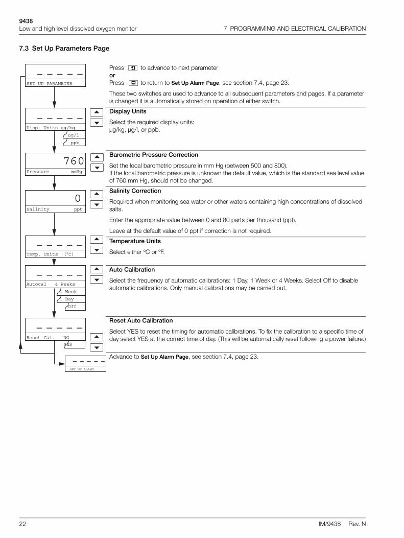
7.3 Set Up Parameters Page
Press to advance to next parameterorPress to return to Set Up Alarm Page, see section 7.4, page 23.
These two switches are used to advance to all subsequent parameters and pages. If a parameter is changed it is automatically stored on operation of either switch.
Display Units
Select the required display units:µg/kg, µg/l, or ppb.
Barometric Pressure Correction
Set the local barometric pressure in mm Hg (between 500 and 800).If the local barometric pressure is unknown the default value, which is the standard sea level value of 760 mm Hg, should not be changed.
Salinity Correction
Required when monitoring sea water or other waters containing high concentrations of dissolved salts.
Enter the appropriate value between 0 and 80 parts per thousand (ppt).
Leave at the default value of 0 ppt if correction is not required.
Temperature Units
Select either ºC or ºF.
Auto Calibration
Select the frequency of automatic calibrations: 1 Day, 1 Week or 4 Weeks. Select Off to disable automatic calibrations. Only manual calibrations may be carried out.
Reset Auto Calibration
Select YES to reset the timing for automatic calibrations. To fix the calibration to a specific time of day select YES at the correct time of day. (This will be automatically reset following a power failure.)
Advance to Set Up Alarm Page, see section 7.4, page 23.
SET UP PARAMETER
– – – – –
Pressure mmHg
760
Salinity ppt
0
Temp. Units (°C)– – – – –
Disp. Units ug/kg
ug/l
ppb
– – – – –
Autocal 4 Weeks
1 Week
1 Day
Off
– – – – –
SET UP ALARM
– – – – –
Reset Cal. NO
YES
– – – – –
9438Low and high level dissolved oxygen monitor 7 PROGRAMMING AND ELECTRICAL CALIBRATION
IM/9438 Rev. N 23
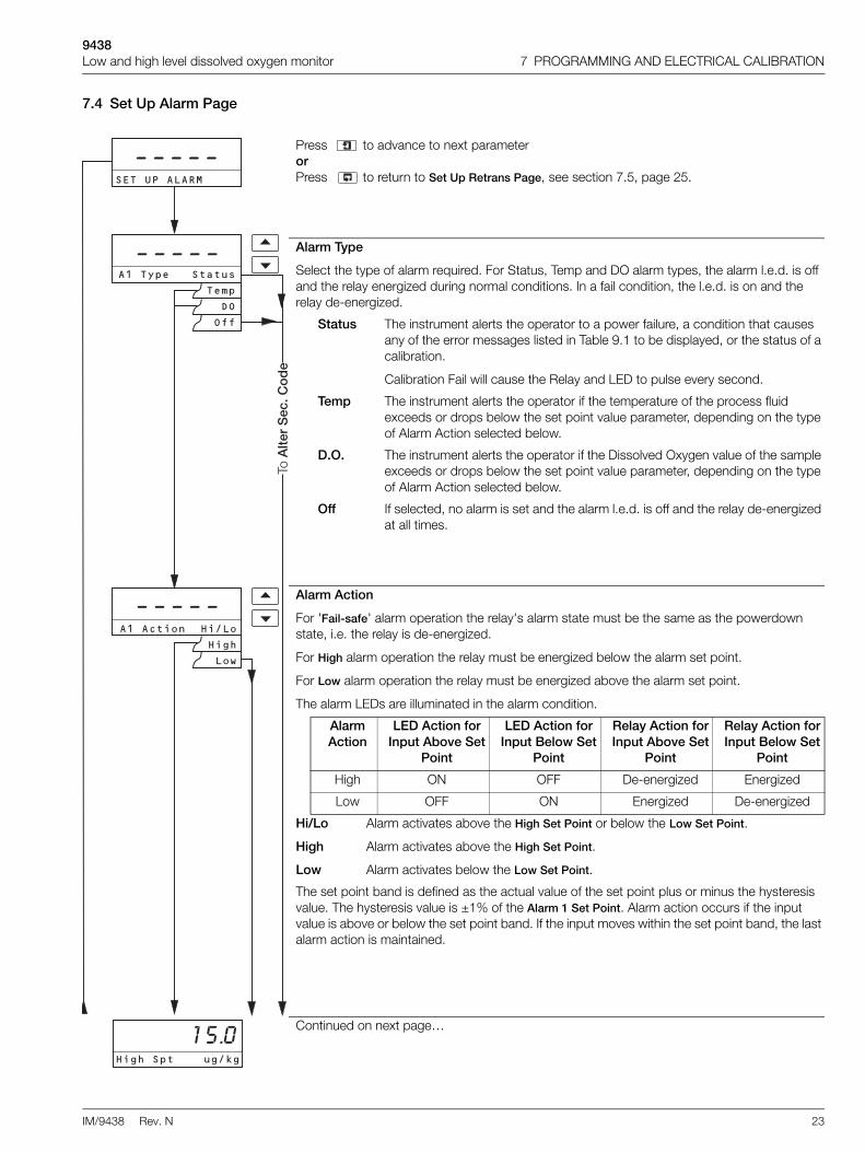
7.4 Set Up Alarm Page
Press to advance to next parameterorPress to return to Set Up Retrans Page, see section 7.5, page 25.
Alarm Type
Select the type of alarm required. For Status, Temp and DO alarm types, the alarm l.e.d. is off and the relay energized during normal conditions. In a fail condition, the l.e.d. is on and the relay de-energized.
Status The instrument alerts the operator to a power failure, a condition that causes any of the error messages listed in Table 9.1 to be displayed, or the status of a calibration.
Calibration Fail will cause the Relay and LED to pulse every second.
Temp The instrument alerts the operator if the temperature of the process fluid exceeds or drops below the set point value parameter, depending on the type of Alarm Action selected below.
D.O. The instrument alerts the operator if the Dissolved Oxygen value of the sample exceeds or drops below the set point value parameter, depending on the type of Alarm Action selected below.
Off If selected, no alarm is set and the alarm l.e.d. is off and the relay de-energized at all times.
Alarm Action
For 'Fail-safe' alarm operation the relay's alarm state must be the same as the powerdown state, i.e. the relay is de-energized.
For High alarm operation the relay must be energized below the alarm set point.
For Low alarm operation the relay must be energized above the alarm set point.
The alarm LEDs are illuminated in the alarm condition.
Alarm Action
LED Action for Input Above Set
Point
LED Action for Input Below Set
Point
Relay Action for Input Above Set
Point
Relay Action for Input Below Set
Point
High ON OFF De-energized Energized
Low OFF ON Energized De-energized
Hi/Lo
High
Low
Alarm activates above the High Set Point or below the Low Set Point.
Alarm activates above the High Set Point.
Alarm activates below the Low Set Point.
The set point band is defined as the actual value of the set point plus or minus the hysteresis value. The hysteresis value is ±1% of the Alarm 1 Set Point. Alarm action occurs if the input value is above or below the set point band. If the input moves within the set point band, the last alarm action is maintained.
Continued on next page…
��-.����/
� � � � �
0�+2���+, +
� ��
� � � � �
� � � � ����)����0�,��
0�+2
��3
���1������&
����
��
�44
������� �$��)���1�
9438Low and high level dissolved oxygen monitor 7 PROGRAMMING AND ELECTRICAL CALIBRATION
24 IM/9438 Rev. N
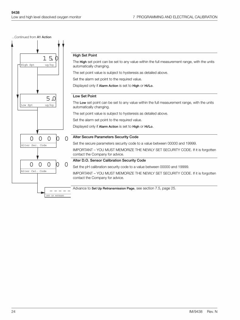
High Set Point
The High set point can be set to any value within the full measurement range, with the units automatically changing.
The set point value is subject to hysteresis as detailed above.
Set the alarm set point to the required value.
Displayed only if Alarm Action is set to High or Hi/Lo.
Low Set Point
The Low set point can be set to any value within the full measurement range, with the units automatically changing.
The set point value is subject to hysteresis as detailed above.
Set the alarm set point to the required value.
Displayed only if Alarm Action is set to High or Hi/Lo.
Alter Secure Parameters Security Code
Set the secure parameters security code to a value between 00000 and 19999.
IMPORTANT – YOU MUST MEMORIZE THE NEWLY SET SECURITY CODE. If it is forgotten contact the Company for advice.
Alter D.O. Sensor Calibration Security Code
Set the pH calibration security code to a value between 00000 and 19999.
IMPORTANT – YOU MUST MEMORIZE THE NEWLY SET SECURITY CODE. If it is forgotten contact the Company for advice.
Advance to Set Up Retransmission Page, see section 7.5, page 25.
High Spt ug/kg
1 5 0.
Low Spt ug/kg
5 0.
Alter Sec. Code
0 0 0 0 0
Alter Cal. Code
0 0 0 0 0
SET UP RETRANS
– – – – –
...Continued from A1 Action

9438Low and high level dissolved oxygen monitor 7 PROGRAMMING AND ELECTRICAL CALIBRATION
IM/9438 Rev. N 25
7.5 Set Up Retransmission PageIn this section the actual values denoted by 'xxxxx' are unimportant and are used to determine display reading stability when carryingout the electrical calibration procedure.
Press to advance to next parameterorPress to return to Factory Settings Page, see section 7.7, page 29.
Set Up Retransmission 1
Retransmission 1 Output Range
The retransmission 1 output can be selected from three mA current ranges to ensure compatibility with the peripheral device connected.Select the current range required for retransmission 1 output.
Retransmission 1 Output Scale
Select the retransmission output scale required.
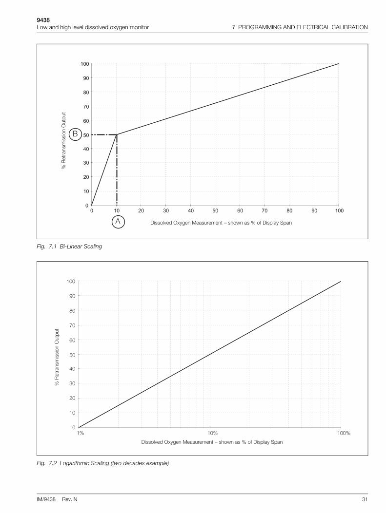
Log (logarithmic) – see Fig. 7.2.Bi-Linear – see Fig. 7.1.Linear
Note for Bi-linear and log scales. The accuracy specification of the instrument should always be given consideration when setting the scale limits to avoid impractical discrimination on the retransmission output.
Retransmission 1 Span
The span current output can be set to any value between:
Linear Bi-Linear Log
20 µg kg–1 and 20 mg kg–1
20 µg kg–1 and 20 mg kg–1
100 µg kg–1 and 20 mg kg–1
Retransmission 1 Zero
The zero current output can be set to any value between 1.0 µg kg–1 and 200 µg kg–1. This is available only for logarithmic output.
Note. For linear output, the zero value is always 0 mg kg–1
Enter Input %
Set the percentage of the display span at which the breakpoint occurs: 1.0 to 100% in 0.1% increments. This is point A on Fig. 7.1.
Enter Output %
Set the percentage output at which the breakpoint occurs: 0.0 to 100% in 0.1% steps. This is point B on Fig. 7.1.
Diagnostics
Select whether the current output diagnostics are required. See Appendix B.
Continued on next page…
SET UP RETRANS
– – – – –
– – – – –
SET UP RETRANS 1
– – – – –
Log
Bi-
Lin
ea
r
Y e s
Lin
ea
r
RTX Type 4-20
0-20
0-10
RTX. Log
Bi-Linear
Linear
– – – – –
2 0 0.RTX Span mg/kg
2 0.RTX Zero mg/kg
1 0 0.Enter Input %
5 0 0.Enter Output %
Diagnostics YES
NO
N o

9438Low and high level dissolved oxygen monitor 7 PROGRAMMING AND ELECTRICAL CALIBRATION
26 IM/9438 Rev. N
Calibration Pulse time
Set the frequency of the calibration pulse signal. Programmable frequency of 15, 30, 45 seconds, 1, 2, 3, 4, 5 minutes.See Appendix B.
Calibration Fail Mark Time
Set the mark time period for the current output to be driven hard upscale. Programmable period of 30 seconds, 1, 2, 3, 4, 5,…,10 minutes.See Appendix B.
Calibration Fail Space Time
Set the space time period for the current output to be driven to 0%. Programmable period of 30 seconds, 1, 2, 3, 4, 5, …,10 minutes.See Appendix B.
Set Up Retransmission 2 – see also Table 7.1.
Note. Available only on 9438 800 series instruments.
Retransmission 2 Output Range
The retransmission 2 output can be selected from three mA current ranges to ensure compatibility with the peripheral device connected. Select the current range required for retransmission 2 output.
Retransmission 2 Output Assignment
Select the Retransmission output required:Temp – TemperatureD.O. – Dissolved Oxygen
Retransmission 2 Output Scale
Select the retransmission output scale required. Only available if D.O. selected.
Log (Logarithmic) – see Fig. 7.2.Bi-Linear – see Fig. 7.1.Linear
Note for Bi-linear and log scales. The accuracy specification of the instrument should always be given consideration when setting the scale limits to avoid impractical discrimination on the retransmission output.
Retransmission 2 Span
Set the span to the required value. See Table 7.1 for details.
Retransmission 2 Zero
Set the zero to the required value. See Table 7.1 for details.
Continued on next page…
SET UP RETRANS 2
– – – – –
Cal. Time s
3 0
Fail M.time s
3 0
Fail S.time s
3 0
– – – – –
Log
Bi-
Lin
ea
r
Lin
ea
r
RTX Type 4-20
0-20
0-10
RTX. Log
Bi-Linear
Linear
– – – – –
RTX O/P Temp
D.O.
– – – – –
Temp D.O.
2 0 0.RTX Span mg/kg
oC
2 0.RTX Zero mg/kg
oC
Yes
No
If N
O R
etra
ns 2
, go
to T
est R
etra
ns (%
)

9438Low and high level dissolved oxygen monitor 7 PROGRAMMING AND ELECTRICAL CALIBRATION
IM/9438 Rev. N 27
Enter Input %
Set the percentage of the display span at which the breakpoint occurs: 1.0 to 100% in 0.1% increments. This is point A on Fig. 7.1.
Enter Output %
Set the percentage output at which the breakpoint occurs: 0.0 to 100% in 0.1% steps. This is point B on Fig. 7.1.
Diagnostics
Select whether the current output diagnostics are required. See Appendix B.
Calibration Pulse Time
Set the frequency of the calibration pulse signal. Programmable frequency of 15, 30, 45 seconds, 1, 2, 3, 4, 5 minutes.See Appendix B.
Calibration Fail Mark Time
Set the mark time period for the current output to be driven hard upscale. Programmable period of 30 seconds, 1, 2, 3, 4, 5, …,10 minutes.See Appendix B.
Calibration Fail Space Time
Set the space time period for the current output to be driven to 0%. Programmable period of 30 seconds, 1, 2, 3, 4, 5, …,10 minutes.See Appendix B.
Test Retransmission Output
The instrument automatically transmits a test signal of 0, 25, 50, 75 or 100% of the retransmission range selected above. The % test signal selected is shown on the upper display.Example – for a selected range of 0 to 20 mA and 50% retransmission test signal, 10 mA is transmitted.
Select the required retransmission test signal.
Advance to Factory Settings Page, see section 7.7, page 29.
Ye s
1 0 0.Enter Input %
5 0 0.Enter Output %
Diagnostics YES
NO
FACTORY SETTINGS
– – – – –
Bi-linear Linear
Cal. Time s
3 0
Fail M.time s
3 0
Fail S.time s
3 0
Test Retrans. (%)
0 0
turn toT UP RETRANS
No Retrans 2
N o

9438Low and high level dissolved oxygen monitor 7 PROGRAMMING AND ELECTRICAL CALIBRATION
28 IM/9438 Rev. N
7.6 Electrical Calibration
7.6.1 Equipment Required1. Current source: 0 to +100 µA.
2. Decade resistance box (temperature input simulator): 0 to 1 k 5 .
3. Digital milliammeter (current output measurement): 0 to 20 mA.
7.6.2 Preparation1. Switch off the supply and disconnect the sensor, temperature compensator and current output from the electronics unit
terminal block – see Fig. 3.5 or Fig. 3.6.
2. Connect the current source / resistance box to the appropriate terminals – see Table 7.2.
Connect the milliammeter to the retransmission output terminals – see Fig. 3.5 or Fig. 3.6.
3. Switch on the supply and allow ten minutes for the circuits to stabilize.
4. Select the Factory Settings Page and carry out the procedure in Section 7.7.
Retransmission 2 Output Assignment
Retransmission 2 Zero Retransmission 2 Span
Dissolved Oxygen LinearBi-LinearLog
= 0 mg kg–1
= 0 mg kg–1
= 1.0 µg kg–1 and 200 µg kg–1
LinearBi-LinearLog
= 20 µg kg–1 and 20 mg kg–1
= 20 µg kg–1 and 20 mg kg–1
= 100 µg kg–1 and 20 mg kg–1
Temperature (ºC)(Subject to minimum range of 20ºC)
5 (minimum) 55 (maximum)
Temperature (ºF)(Subject to minimum range of 36ºF)
41 (minimum) 131 (maximum)
Table 7.1 Retransmission 2
Note. The instrument is calibrated by the company prior to despatch and an electrical calibration should be carried out only if the accuracy of the instrument is suspect and suitably calibrated test equipment is available.
Note. Resistance boxes have an inherent residual resistance which may range from a few milliohms up to 1 ohm. This value must be taken into account when simulating input levels, as should the overall tolerance of the resistors within the boxes.
Instrument Type Terminal
Wall Mounted 1 2 3 4 5 6 7
Panel Mounted 12 11 10 9 8 7 6
+ve current input
–ve current input
PT1000 input Link to terminal 7 (6)
PT1000 input
Table 7.2 Transmitter Terminal Functions

9438Low and high level dissolved oxygen monitor 7 PROGRAMMING AND ELECTRICAL CALIBRATION
IM/9438 Rev. N 29
7.7 Factory Settings PageWhen carrying out the electrical calibration procedure, the actual values denoted by xxxxx are unimportant and are used only todetermine display reading stability.
Press to advance to next parameterorPress to return to Operating Page, see section 6.2.1, page 19.
Parameters in these pages are factory set and should not normally require adjustment. They can be set up only if the necessary equipment is available.
Factory Settings Access Code
Enter the required code number. If an incorrect value is entered, access to subsequent parameters is prevented and the display reverts to the top of the page.
Select YES to access the electrical calibration sequence. Select NO to advance to Cal Time 1.
Caution. Do not select YES unless instrument calibration is required.
Microamp Zero
Set the current source to 0 µA and allow the instrument display to stabilize.
Microamp Span
Set the current source to +100 µA and allow the instrument display to stabilize.
Calibrate Temperature Zero
Set the temperature simulator resistance box to 1000 and allow the instrument display to stabilise.
Calibrate Temperature Span
Set the temperature simulator resistance box to 1500 and allow the instrument display to stabilise.
Adjust Retransmission Zero
Set the milliammeter reading to 4.00 mA.
Note. Retransmission signal span is calibrated using 20.00 mA. The correct value transmitted depends on the range selected in the Set Up Outputs Page.
Continued on next page…
FACTORY SETTINGS
– – – – –
μA Zero (0μA)X X X X
FACTORY SET CODE
0 0 0 0
ELECTRICAL CAL
– – – – –
Calibrate YES
NO
– – – – –
μA Span (100μA)X X X X
Temp Zero (1k0)
X X X X
YESNO
Temp Span (1k5)
X X X X
Adjust RTX Zero
– – – – –

9438Low and high level dissolved oxygen monitor 7 PROGRAMMING AND ELECTRICAL CALIBRATION
30 IM/9438 Rev. N
Adjust Retransmission Span
Set the milliammeter reading to 20.00 mA.
Note. Retransmission signal span is calibrated using 20.00 mA. The correct value transmitted depends on the range selected in the Set Up Outputs Page.
Adjust Retransmission Zero 2
See Adjust Retransmission Zero.
Adjust Retransmission Span 2
See Adjust Retransmission Span.
Calibration Time 1
Wait period before the stability of the sensor is checked during the calibration sequence. Programmable from 1 to 10 minutes (default = 2 minutes), see section 7.5, page 25.
Calibration Time 2
Recovery period where the sample is allowed to flow and the instrument settles on reading, before the instrument is brought back on-line (default = 30 minutes), see section 7.5, page 25.
Alter Factory Setting Security Code
Set the security code to a value between 00000 and 19999.
Return to Operating Page, see section 6.2.1, page 19.
�$%�&���'���� � � � �
�������� ����"
�
�������( ����"
��
�������)�*��$�
���������
�*�* F+, +
� � �
�$%�&���'����(� � � � �
�$%�&���'���(� � � � �
9438Low and high level dissolved oxygen monitor 7 PROGRAMMING AND ELECTRICAL CALIBRATION
IM/9438 Rev. N 31
Fig. 7.1 Bi-Linear Scaling
Fig. 7.2 Logarithmic Scaling (two decades example)
������.���/&01����� ���������)��3�5�� ��G��6���� � 0�� �
G�>��� ����������/�� ��
�
��
��
��
��
��
��
!�
��
��
���
� �� �� �� �� �� �� !� �� �� ���
$
8
������.���/&01����� ���������)��3�5�� ��G��6���� � 0�� �
G�>��� ����������/�� ��
%G %��G%�G�
%�
��
�
�
'�
,�
@�
��
��
%��

9438Low and high level dissolved oxygen monitor 8 MAINTENANCE
32 IM/9438 Rev. N
8 MAINTENANCE8.1 IntroductionNo routine maintenance is required for this instrument other thanperiodic calibration – see section 6.2.2, page 20. However, iffollowing a calibration the sensor output shows one flashing bar,the sensor capsule has therefore become exhausted and needsreplacing immediately.
If the output shows two bars, replace the sensor capsule in thenear future.
A dirty membrane may also be the cause of the low sensoroutput. To clean the sensor proceed with the following.
8.2 Cleaning/Changing the Sensor
8.2.1 Cleaning1. Drain the flowcell, by manually opening the solenoid valve
– Select YES to 'Open Valve' on the main operating pageof the transmitter – see section 6.2.1, page 19.
2. Unscrew the clamping screw and carefully remove thesensor assembly from the flowcell. Check that O-ringdoes not fall out.
3. Inspect the sensor. If the membrane is clean, refit thesensor as in 5) below.
If deposits are visible on the membrane, remove by gentlywiping the membrane with a moist paper tissue; for oily orgreasy deposits, the tissue may be moistened with a milddetergent or, if necessary with iso-propyl alcohol(propan-2-ol). After cleaning, dry the interior of the flowcellwith a paper tissue or soft cloth, ensure that the O-ring iscorrectly positioned.
4. Insert the sensor assembly into the flowcell.
5. Use the clamp screw to secure the assembly. Screw infirmly using finger pressure only.
6. Close the solenoid valve – Select NO to 'Open Valve' onthe main operating page of the transmitter – see section6.2.1, page 19.
7. Carry out a calibration – see section 6.2.2, page 20. If alow sensor efficiency is displayed, see section 9.2, page35.
Note. Storage.
DO:
use sensors in date rotation to prevent them being stored longer than necessary.
at all times, store sensors in a dry and cool environment.
store sensors in a refrigerator to extend their life, but DO NOT allow them to freeze.
DO NOT:
allow sensors to dry out, either in storage or in use.
leave sensors in vehicles where they are likely to freeze or be exposed to high temperatures.
leave sensors on-site without protection from direct sun or high temperatures.
use the sensor if it's sealed environment has dried out.
Caution.
Only install the oxygen sensor immediately prior to use, otherwise leave it stored in its protective container.
Take special care to line up the two pins in the oxygen sensor with their respective sockets before making the connection and tightening.
Take care not to damage the delicate membrane on the end of the oxygen sensor.
Ensure that the mating surfaces (carrying the electrical connection) of the oxygen sensor and connector body are clean and completely dry.
Caution. Do not overtighten the clamping screw.
9438Low and high level dissolved oxygen monitor 8 MAINTENANCE
IM/9438 Rev. N 33
8.2.2 Changing the Sensor1. Drain the flowcell, by manually opening the solenoid valve
– Select YES to 'Open Valve' on the main operating pageof the transmitter, see section 6.2.1, page 19.
2. Unscrew the clamping screw and remove the sensorassembly from the flowcell.
3. Disconnect the sensor capsule and discard both thesensor and sealing washer.
4. Take out the O-ring from the flowcell; dry the interior of theflowcell with a tissue or soft cloth and insert the newO-ring supplied with the replacement capsule. Ensure thatthe O-ring is correctly located on the shoulder near theend of the cavity.
5. Remove the new sensor from its container, taking care notto damage the membrane. Unscrew the protective capfrom the rear of the sensor.
6. Fit the new sealing washer (supplied) as shown in Fig. 4.1and locate and secure the connector body on the sensor.
7. Insert the complete assembly into the flowcell.
8. Use the clamping screw to secure the assembly. Screw infirmly using finger pressure only.
9. Close the solenoid valve – Select NO to 'Open Valve' onthe main operating page of the transmitter, see section6.2.1, page 19.
10. Carry out a calibration – see section 6.2.2, page 20. If alow sensor efficiency is displayed, see section 9.2, page35.
Caution. Do not overtighten the clamping screw.

9438Low and high level dissolved oxygen monitor 9 SIMPLE FAULT FINDING
34 IM/9438 Rev. N
9 SIMPLE FAULT FINDING9.1 Diagnostic MessagesIf erroneous or unexpected results are obtained the fault may be indicated by an error message. If Alarm A1 has been selected as aSTATUS alarm, then the LED and relay operation can be seen in Table 9.1. The STATUS alarm operates as a FAILSAFE alarm (duringan alarm condition the relay state is the same as the power-down state, i.e. de-energized).
Diagnostic Message
STATUS Alarm A1
Possible Cause RemedyLED Action Relay Action(Fail-safe)
Flashing Display OFF Energized Reading is outside of the measuring range 0 to 20 mg Kg–1.
See Sections 9.2 & 9.3.
LOW SENSOR EFF. ON/OFF(1s period)
De-energized/ energized(1s period)
Output from D.O. sensor during calibration less than 40 % of expected output.
See Section 9.2.
SLOW SENSOR CAL.
ON/OFF(1s period)
De-energized/ energized(1s period)
Output from D.O. sensor during calibration not achieving required stability.
See Section 9.2.
Calibrating in Air ON De-energized Displayed during calibration when sensor is exposed to air.
–
Recovery Period ON De-energized Displayed after calibration whilst waiting for sensor to stabilize on sample. Duration of 30 minutes (Cal Time 2).
–
COLD(Solution too cold)
ON De-energized Sample temperature <5 ºC. If sample temperature is not <5 ºC, check the temperature input of the transmitter – see section 9.3, page 35. If fault persists contact the Company.
HOT(Solution too hot)
ON De-energized Sample temperature >55 ºC. This causes the calibration valve to open and drain the flowcell to prevent damage to the sensor. After 30 minutes the valve closes and the sample temperature is measured again. This process continues until the sample temperature is <55 ºC.
If sample temperature is not >55 ºC, check the temperature input of the transmitter – see section 9.3, page 35. If fault persists contact the Company.
FAULTY PT1000 ON De-energized Temperature compensator/ associated connections are either open or short circuit.
Check that all signal connections are made. If fault persists, check for a response to a temperature input – see section 9.3, page 35.
INVALID INPUT ON De-energized Input signal is outside of measuring range of the electronics.
Check that instrument responds to an input signal by carrying out an electrical calibration as described in Section 7.6.
NV MEMORY ERROR
ON De-energized Contents of non-volatile memory have not been read correctly during power up.
Switch off transmitter, wait 10 seconds and switch on again. If fault persists contact the Company.
Table 9.1 Diagnostic Messages

9438Low and high level dissolved oxygen monitor 9 SIMPLE FAULT FINDING
IM/9438 Rev. N 35
9.2 Low Sensor Efficiency/Slow Sensor Cal. or No Response to D.O. Changes
1. Check that the sample drains fully from flowcell. If thesample does NOT drain fully check:
a. Operation of solenoid valve.
b. Sample inlet flow rate does not exceed 400 ml min–1
maximum.
c. Sample fluid paths are free flowing and clear ofpartial blockages.
d. Solenoid valve drain tube is not kinked, blocked,excessively long, does no rise along its length.
e. Flow gauge is not blocked or dirty.
2. Replace the sensor (see section 8.2.2, page 33) as aninitial check. It is also important that all programparameters have been set correctly and have not beenaltered inadvertently – see section 7, page 21.
If the fault persists:
3. Carry out an electrical calibration as detailed in Section 7.6and check that the instrument responds correctly to thecurrent input.
Failure to respond to the input usually indicates a fault withthe transmitter, which must be returned to the Companyfor repair.
4. If the response in a) is correct, select the Operating Pageand set the current source to a value which gives anon-scale D.O. reading on the transmitter. Make a note ofthe current source setting and the D.O. reading.Reconnect the sensor cable and connect the currentsource to the sensor end of the cable. Set the samecurrent value on the source and check that the transmitterdisplays the noted reading in this configuration.
If check 1 is correct but check 2 fails, check the cableconnections and condition. If the response for both checks iscorrect, fit a new sensor and calibrate it.
9.3 Checking the Temperature InputCheck that the instrument responds to a temperature input.Disconnect the PT1000 leads and connect a suitable resistancebox directly to the transmitter inputs – see section 7.6, page 28.Check that the transmitter displays the correct values as set onthe resistance box – see Table 9.2.
Incorrect readings usually indicate an electrical calibrationproblem. Recalibrate the instrument – see section 7.6, page 28.
9.4 High Sample ReadingsIf the sample reading is higher than expected, the most likelyreason is air ingress into the main sample line.
Check and tighten ALL sample connections as it is possible tohave an air leak into the sample without sample leaking.
Temperature (ºC) Input Resistance ()
0 1000.0
10 1039.0
20 1079.3
30 1116.7
40 1155.4
50 1194.0
60 1232.4
70 1270.7
80 1308.9
90 1347.0
100 1385.0
130.5 1500.0
Table 9.2 Temperature Readings for Resistance Inputs
9438Low and high level dissolved oxygen monitor 10 SPECIFICATION
36 IM/9438 Rev. N
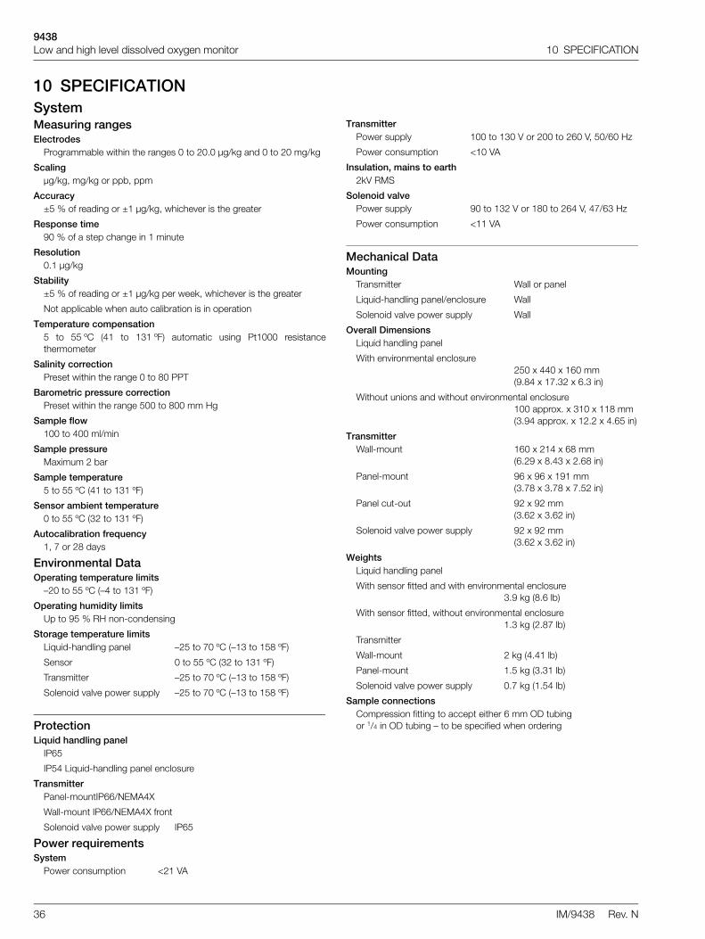
10 SPECIFICATIONSystemMeasuring rangesElectrodes
Programmable within the ranges 0 to 20.0 µg/kg and 0 to 20 mg/kg
Scalingµg/kg, mg/kg or ppb, ppm
Accuracy±5 % of reading or ±1 µg/kg, whichever is the greater
Response time90 % of a step change in 1 minute
Resolution0.1 µg/kg
Stability±5 % of reading or ±1 µg/kg per week, whichever is the greater
Not applicable when auto calibration is in operation
Temperature compensation5 to 55 ºC (41 to 131 ºF) automatic using Pt1000 resistancethermometer
Salinity correctionPreset within the range 0 to 80 PPT
Barometric pressure correctionPreset within the range 500 to 800 mm Hg
Sample flow100 to 400 ml/min
Sample pressureMaximum 2 bar
Sample temperature5 to 55 ºC (41 to 131 ºF)
Sensor ambient temperature0 to 55 ºC (32 to 131 ºF)
Autocalibration frequency1, 7 or 28 days
Environmental DataOperating temperature limits
–20 to 55 ºC (–4 to 131 ºF)
Operating humidity limitsUp to 95 % RH non-condensing
Storage temperature limitsLiquid-handling panel –25 to 70 ºC (–13 to 158 ºF)
Sensor 0 to 55 ºC (32 to 131 ºF)
Transmitter –25 to 70 ºC (–13 to 158 ºF)
Solenoid valve power supply –25 to 70 ºC (–13 to 158 ºF)
ProtectionLiquid handling panel
IP65
IP54 Liquid-handling panel enclosure
TransmitterPanel-mountIP66/NEMA4X
Wall-mount IP66/NEMA4X front
Solenoid valve power supply IP65
Power requirementsSystem
Power consumption <21 VA
TransmitterPower supply 100 to 130 V or 200 to 260 V, 50/60 Hz
Power consumption <10 VA
Insulation, mains to earth2kV RMS
Solenoid valvePower supply 90 to 132 V or 180 to 264 V, 47/63 Hz
Power consumption <11 VA
Mechanical DataMounting
Transmitter Wall or panel
Liquid-handling panel/enclosure Wall
Solenoid valve power supply Wall
Overall DimensionsLiquid handling panel
With environmental enclosure250 x 440 x 160 mm(9.84 x 17.32 x 6.3 in)
Without unions and without environmental enclosure100 approx. x 310 x 118 mm(3.94 approx. x 12.2 x 4.65 in)
TransmitterWall-mount 160 x 214 x 68 mm
(6.29 x 8.43 x 2.68 in)
Panel-mount 96 x 96 x 191 mm(3.78 x 3.78 x 7.52 in)
Panel cut-out 92 x 92 mm(3.62 x 3.62 in)
Solenoid valve power supply 92 x 92 mm(3.62 x 3.62 in)
WeightsLiquid handling panel
With sensor fitted and with environmental enclosure3.9 kg (8.6 lb)
With sensor fitted, without environmental enclosure1.3 kg (2.87 lb)
Transmitter
Wall-mount 2 kg (4.41 lb)
Panel-mount 1.5 kg (3.31 lb)
Solenoid valve power supply 0.7 kg (1.54 lb)
Sample connectionsCompression fitting to accept either 6 mm OD tubingor 1/4 in OD tubing – to be specified when ordering

9438Low and high level dissolved oxygen monitor 10 SPECIFICATION
IM/9438 Rev. N 37
TransmitterTransmitter DisplayMeasured value
5-digit x 7-segment back-lit LCD
Information16-character, single line, dot matrix, back-lit LCD
Insulation, contacts to earth2 kV RMS
Set Point and RelayNo. of set points
One
Set point adjustmentProgrammable as a concentration or diagnostics alarm
Set point hysteresis±1 % of FSD (fixed) Sensor 0 to 55 ºC (32 to 131 ºF)
Local set point annunciationRed LED
No. of relaysTwo – one permanently assigned to the calibration solenoid valve
Relay contactsSingle pole changeover
Rating: 250 V AC 250 V DC max.3 A AC 3 A DC max.
Loading: 750 VA 30 W max. (non-inductive)75 VA 3 W max. (inductive)
RetransmissionNo. of retransmission signals
One, fully isolated current output
0 to 10, 0 to 20 or 4 to 20 mA programmable
Optional second current output0 to 10, 0 to 20 or 4 to 20 mA programmable
Maximum load resistance500 (20 mA maximum)
Serial communicationRS422/RS485 (optional, with one current output signal)
Solenoid Valve PSU
Typical cable specification3-core round 0.5 mm2
Min. current rating 3 A
Construction 16/0.2 mm
Nom. diameter 5.5 to 8.5 mm
Voltage requirements90 to 132 V AC or180 to 264 V AC, 47 to 63 Hz
Power consumption<60 VA max.
Output power24 V @ 2.5 A, 60 W max. from all outputs
Holdup time6 ms at full load 115/230 V AC
Line regulation0.3 % over operating range
Load regulation0.5 % from min. load to full load
Note. Cable from the PSU to the valve is not supplied by ABB
9438Low and high level dissolved oxygen monitor 11 SPARES
38 IM/9438 Rev. N
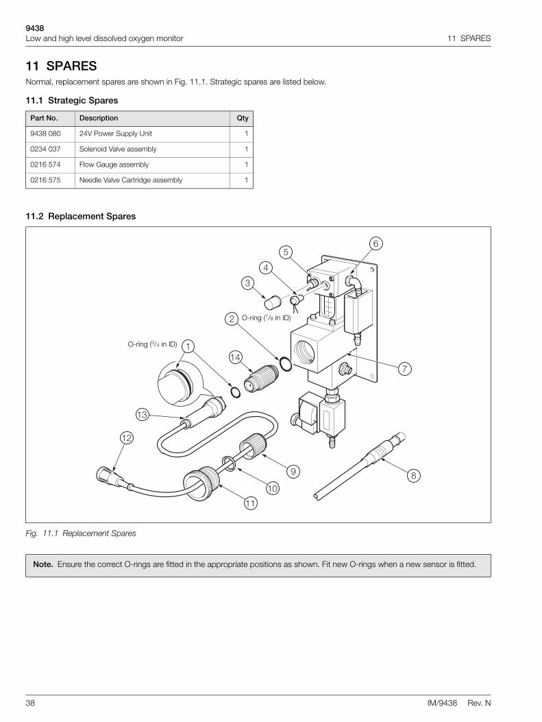
11 SPARESNormal, replacement spares are shown in Fig. 11.1. Strategic spares are listed below.
11.1 Strategic Spares
11.2 Replacement Spares
Part No. Description Qty
9438 080 24V Power Supply Unit 1
0234 037 Solenoid Valve assembly 1
0216 574 Flow Gauge assembly 1
0216 575 Needle Valve Cartridge assembly 1
Fig. 11.1 Replacement Spares
1
2
3
4
56
7
89
10
11
12
14
13
O-ring (3/4 in ID)
O-ring (7/8 in ID)
Note. Ensure the correct O-rings are fitted in the appropriate positions as shown. Fit new O-rings when a new sensor is fitted.

9438Low and high level dissolved oxygen monitor 11 SPARES
IM/9438 Rev. N 39
Item Description Part Number
123456
Replacement seals pack, comprising items 1 to 6:
2 x Small O-rings ((3/4 in ID)
2 x Large O-rings (7/8 in ID)
2 x End caps (used to blank off this connector when the plug is not fitted)1 x Protective coverO-ring2 x Nylon seals
9435 016
7 Flowcell 9438 015
8 Sensor connector cable assembly:
1 m (3 ft)5 m (18 ft.)10 m (33 ft.)30 m (100 ft)
9437 0299437 0319437 0329437 034
9jklm
Handle assembly, comprising items 9 to m:
Connector nutThrust washerClamping screwPlugConnector body
9437 025
n Oxygen sensor (including O-rings) 9435 300
Table 11.1 Replacement Part Numbers

9438Low and high level dissolved oxygen monitor Appendix A 9438 080 24 V DC POWER SUPPLY UNIT (OPTIONAL)
40 IM/9438 Rev. N
Appendix A 9438 080 24 V DC POWER SUPPLY UNIT (OPTIONAL) A.1 DescriptionThe 24 V DC switch mode power supply unit is capable ofpowering up to four separate 9438 dissolved oxygen systemsolenoids. The 24 V is switched to the solenoid when requiredby the operation of the calibration relay in the main 9438transmitter.
Fig. A.3 shows the connection details in the PSU.
Fig. A.4 shows the interconnection between the PSU and asingle 9438 transmitter.
A.2 PSU Dimensions
A.3 Accessing PSU Terminals
Warning.
Before making any connections, ensure that the power supply, any high voltage-operated control circuits and high common mode voltage are switched off.
Although certain instruments are fitted with internal fuse protection, a suitably rated external protection device, e.g. fuse or miniature circuit breaker (m.c.b.), must also be fitted by the installer.
Fig. A.1 Power Supply Unit Dimensions
�
$�������������������
�=������ :�� ���5 �"��6���" 7���7����
%,�
,��>
�6�&��1
��
%'���>�
%,
,�
�,������6��� ��3
7�����1 4�&��1��"��5���
Fig. A.2 Access to PSU Terminals
�� ":���" ��.���"��5�
9438Low and high level dissolved oxygen monitor Appendix A 9438 080 24 V DC POWER SUPPLY UNIT (OPTIONAL)
IM/9438 Rev. N 41
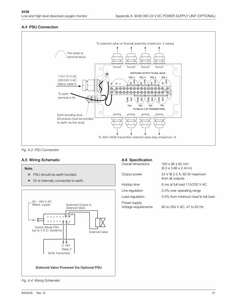
A.4 PSU Connection
A.5 Wiring Schematic A.6 SpecificationOverall dimensions 160 x 98 x 62 mm
(6.3 x 3.86 x 2.44 in)
Output power 24 V @ 2.5 A, 60 W maximum from all outputs
Holdup time 6 ms at full load 115/230 V AC
Line regulation 0.3% over operating range
Load regulation 0.5% from minimum load to full load
Power supplyVoltage requirements 90 to 264 V AC, 47 to 63 Hz
Fig. A.3 PSU Connection
����5������������� ��7��":
%%�A%%'���$���A�����$�� ����" 7�����
���� ��3������ ��������
���,%A,,��� ������������������. �.����� 0��� &����H�!
������������. �.�����6��5"���� ����7�0��� &����H��. �.��!
- ��3�7�����1�������-�"������������7��7��������� ��3�.� ��3�������!
�8�&���:�(�87��&�!$�����&$
$����;���8 �" ���8�$8��5��5�
�������!����� <5 /(+5
<5 /(+5
<5 /(+5
<5 /(+5
�6+ �6* �6( �6'
$8��+ $8��* $8��( $8��'
�8�
!=8
�8�
!=8
�8�
!=8
�8�
!=8
Note.
PSU should be earth bonded.
0V is internally connected to earth.
Fig. A.4 Wiring Schematic
$�����1�5�����"�#� �1�5���8�������"$
����� ��������>�� 0�����=/
���������� �.�
���)��,���$�� ������� �0
�5��"3����������� �������/���0�����!
�5��"3���/�� ��������������� �.�
�� C��
� =A/

9438Low and high level dissolved oxygen monitor Appendix B CALIBRATION DIAGNOSTICS
42 IM/9438 Rev. N
Appendix B CALIBRATION DIAGNOSTICSThe transmitter can be configured to enable the current output signal to indicate certain calibration diagnostic information.If the option for diagnostics is selected within the Set Up Retransmission scrolls, then the current output will indicate when acalibration is taking place, and also will indicate if the sensor is giving Low Sensor Efficiency.
B.1 During CalibrationThe current output value will be maintained during a calibration, but the output will pulse from the maintained value to 0%, dependingupon a programmable Cal Pulse period.The Calibration Pulse period can be programmed 15, 30, 45 seconds, 1, 2, 3, 4, 5 minutes.
This will continue for the full duration of the calibration, exposing the sensor to air, and the recovery period. At the end of the recoveryperiod, if the response is good, the instrument will go back on line and the current output will become live.
Fig. B.1 During Calibration
� �������
-& �������$�� >�"�.��0�����������
8�������� ���0>
2
,<
'<<
<

9438Low and high level dissolved oxygen monitor Appendix B CALIBRATION DIAGNOSTICS
IM/9438 Rev. N 43
B.2 Low Sensor EfficiencyIf the output from a sensor is found to be below a predetermined level during a calibration (i.e. Low Sensor Efficiency) the calibrationwill not be accepted. The current output immediately goes above the full scale value, and will continue to pulse on a programmableMark/Space basis.
The time for the Mark and Space periods can be programmed separately to 30 seconds, 1, 2, 3…..10 minutes.
Fig. B.2 Low Sensor Efficiency
� �:��������'����!
-& �������$��
8�������� ���0>
2
,<
'<<
� "���������'����!
<
����

9438Low and high level dissolved oxygen monitor Notes
44 IM/9438 Rev. N
Notes

Products and customer supportAutomation SystemsFor the following industries:— Chemical & Pharmaceutical— Food & Beverage— Manufacturing— Metals and Minerals— Oil, Gas & Petrochemical— Pulp and Paper
Drives and Motors— AC and DC Drives, AC and DC Machines, AC Motors to
1kV— Drive Systems— Force Measurement— Servo Drives
Controllers & Recorders— Single and Multi-loop Controllers— Circular Chart and Strip Chart Recorders— Paperless Recorders— Process Indicators
Flexible Automation— Industrial Robots and Robot Systems
Flow Measurement— Electromagnetic Flowmeters— Mass Flowmeters— Turbine Flowmeters— Wedge Flow Elements
Marine Systems & Turbochargers— Electrical Systems— Marine Equipment— Offshore Retrofit and Refurbishment
Process Analytics— Process Gas Analysis— Systems Integration
Transmitters— Pressure— Temperature— Level— Interface Modules
Valves, Actuators and Positioners— Control Valves— Actuators— Positioners
Water, Gas & Industrial Analytics Instrumentation— pH, Conductivity and Dissolved Oxygen Transmitters and
Sensors— Ammonia, Nitrate, Phosphate, Silica, Sodium, Chloride,
Fluoride, Dissolved Oxygen and Hydrazine Analyzers— Zirconia Oxygen Analyzers, Katharometers, Hydrogen
Purity and Purge-gas Monitors, Thermal Conductivity
Customer supportWe provide a comprehensive after sales service via a Worldwide Service Organization. Contact one of the following offices for details on your nearest Service and Repair Centre.
UKABB LimitedTel: +44 (0)1453 826661Fax: +44 (0)1453 829671
USAABB Inc.Tel: +1 215 674 6000Fax: +1 215 674 7183
Client WarrantyPrior to installation, the equipment referred to in this manual must be stored in a clean, dry environment, in accordance with the Company's published specification.Periodic checks must be made on the equipment's condition. In the event of a failure under warranty, the following documentation must be provided as substantiation:— A listing evidencing process operation and alarm logs
at time of failure.— Copies of all storage, installation, operating and
maintenance records relating to the alleged faulty unit.

Contact us
IM/9
438
Rev
. N05
.201
2ABB LimitedProcess AutomationOldends LaneStonehouseGloucestershire GL10 3TAUKTel: +44 1453 826 661Fax: +44 1453 829 671
ABB Inc.Process Automation125 E. County Line RoadWarminsterPA 18974USATel: +1 215 674 6000Fax: +1 215 674 7183
www.abb.com
NoteWe reserve the right to make technical changes or modify the contents of this document without prior notice. With regard to purchase orders, the agreed particulars shall prevail. ABB does not accept any responsibility whatsoever for potential errors or possible lack of information in this document.
We reserve all rights in this document and in the subject matter and illustrations contained therein. Any reproduction, disclosure to third parties or utilization of its contents in whole or in parts – is forbidden without prior written consent of ABB.
Copyright© 2012 ABBAll rights reserved


![Dissolved Oxygen [DO]](https://static.fdocuments.in/doc/165x107/5a6721977f8b9ab12b8b464b/dissolved-oxygen-do.jpg)


