94.2.910.55en E 2009 03 13 Pulse shaper stage (programmable logic) x Trip circuit supervision 74TC x...
28
© Sprecher Automation 2009 TECHNICAL BROCHURE ENGLISH ONEBOX SOLUTION FOR PROTECTION AND CONTROL OVERCURRENT TIME PROTECTION DS6 – DSE6 – DSR6 – DSRE6 – DSREY6 SPRECON ® -E-P94-DS..6
Transcript of 94.2.910.55en E 2009 03 13 Pulse shaper stage (programmable logic) x Trip circuit supervision 74TC x...

© Sprecher Automation 2009
TECHNICAL BROCHURE ENGLISH
ONEBOX SOLUTION FOR PROTECTION AND CONTROLOVERCURRENT TIME PROTECTION DS6 – DSE6 – DSR6 – DSRE6 – DSREY6
SPRECON®-E-P94-DS..6

2 www.sprecher-automation.com
Overview SPRECON®-E-P94-DS..6 is a one-box solution for protection and control, which guarantees over-current time protection of primary equipment by simultaneously accomplishing control and monitoring functions in electric power systems.
Fig. 1: Configuration example and typical applications
Areas of application Thanks to the different models of the over-current time protection and its implemented functions, SPRECON®-E-P94-DS..6 can be used for many different protection and control applications. It can be therefore applied to all switchbay types, independent of customer-specific requirements. The implemented protection functions allow selective protection of:
Electric lines (underground and overhead lines) Transformers Motors
The device is especially predestinated for the following application areas due to its comprehensive miscellaneous functions:
One-box solution for utilities (MV) Bay computer with back-up protection (HV) Industrial switchgears
Range of functions All necessary secondary system-based tasks can be carried out by SPRECON®-E-P94-DS..6:
Comprehensive protection of various primary systems
Control and monitoring of switching devices and process components
Recording of measured values Communication with superior control or remote control systems
Integration of other control system devices such as AVRs
Bay control and monitoring The device is accentuated by a technologically fully developed and commercially optimized design. It allows realization of sophisticated and compact solutions with clear economical benefits through highest possible flexibility and scalability.

3© Sprecher Automation 2009
Concept Consequently separation of control and protection technology together with approved algorithms of digital signal processing provides security, offers availability and reliability at the highest possible level.
separated data model separated processes separated firmware Separated passwords No protection check of the feed and disconnection in the primary circuit during update of the control parameters and control firmware necessary
Modern technologies prevent mutual effects between tasks whereby as far as possible independence between the applications can be achieved. So for example it is possible to load firmware and data model of the protection independent of the control part and vice versa.. The operator faces a clear separation of control and protection, which allows either combined or separated operations of control and protection functions.
Fig. 2: Functional overview
Configuration All implemented functions can be configured separately. Different requirements are met at the best for all customers through the separation of protection and control system configuration. As against, the protection-specific functions can be configured or deactivated separately depending on the particular application. Irrelevant functions are hidden and inactive, which allows simple and structured device configuration. The concept of database-supported type orientation towards bay types is applied to the control system configuration, which therefore facilitates the de-velopment of comprehensive systems to a large extend.
Operation In order to meet the requirements of efficient system management, all operations can be accomplished via the separated HMI control panel. Hence, pro-tection configurations can be locally carried out beside usage of the configuration program “COMM-3“. On the full graphics LCD, all necessary information about processes and devices are displayed. Additionally, free configurable LEDs are available for signaling. Separated navigation keys allow clear user guidance through the various menu pages and simple configuration of extensive protection functions.
IEC 60870-5-101
IEC 61850IEC 60870-5-104
IEC 60870-5-103
SPRECON-E COMM-3SPRECON-E DESIGNER

4 www.sprecher-automation.com
Protection functions Implemented protection functions IEEE C37.2 IEC
61850-7-4 DS6 3 x IL, 1 x IE
DSE6 3 x IL, 1 x IE, 1 x UNE
DSR6 3 x IL, 3 x ULE
DSRE63 x IL, 1 x IE, 3 x ULE
DSREY6 3 x IL, 1 x IE, 3 x ULE, 1 x USync
Overcurrent protection IL> DT / IDMT, four stages
50, 51
PIOC, PTOC
x
x
x
x
x
IE> DT / IDMT, four stages 50N, 51N, 51Ns PIOC, PTOC x x x x x Switch on protection (SOTF, SOP) 50, 50N PIOC x x x x x Inrush restraint PHAR x x x x x Short circuit direction decision 67 PTOC, RDIR x x x Directional earth fault 67N PTOC x x x Phase-selective earth-fault detection 64 PHIZ x x x Earth-fault direction decision 67Ns PSDE x x x Detection ext. earth fault direction annunciation (PTEF, PSDE) x x Auto-reclosing (AR) 79 RREC 3-pole 3-pole 3-pole 3-pole 3-pole Teleprotection (TP) 85 PSCH (x) (x) x x x Voltage time protection Overvoltage (U>, UNE>), two stages each
59, 59N
PTOV
UNE>
x
x
x
Undervoltage (U<), two stages 27 PTUV x x x Frequency protection (f<, f>), four stages 81 PTUF, PTOF x x x Negative sequence system Ineg> 46 PTOC x x x x x Overload protection 49 PTTR x x x x x Temperature protection1 49 STMP option option option option option Starting protection (motor protection) 49R, 66, 48 PMRI x x x x x Locked rotor (motor protection) 14, 51LR PMSS x x x x x Underload protection (motor protection) 37 PTUC x x x x x Reclosing lockout 86 PMRI x x x x x Circuit breaker failure protection (CBF) 50BF PTOC, RBRF x x x x x Automatic synchronizer 25 RSYN x Current annunciation stages (2x IL>an, 1x IE>an) x x x x x CB-TRIP via an external signal (PTRC) x x x x x Fault locator (FL) 21FL RFLO x x x Phase-sequence reversal x x x x x Pulse shaper stage (programmable logic) x x x x x Trip circuit supervision 74TC x x x x x Parameter sets 4 4 4 4 4 Logic + time stages for optocoupler inputs x x x x x virtual binary inputs (vBI) 15 15 15 15 15 Logic + hold time for output relays x x x x x Process measurement, short report x x x x x Event logging, non-volatile RDRE x x x x x Disturbance data recording, non-volatile RADR, RBDR x x x x x Statistics x x x x x Measurement check, watch-dog x x x x x Test- and commissioning utilities x x x x x
1 only possible with AI-/ PT100 module
5© Sprecher Automation 2009
Control functions Control and monitoring of switchgears and other processes
Control outputs with high make/break capacity (e.g. direct control of disconnector motors)
Direct or select before operate based command sequence
Control of tap changers for transformers and Petersen coils
Configurable bay interlocking Switching authority and cross-functional switch-gear interlocking (Sprecher station control)
Programmable substation automatic functions Programmable logics Blocking of switching devices Group-assigned indication and measured-value blocking
Threshold-value monitoring Maximum demand value calculation Maximum value calculation (non-return pointer) Configurable transmission modes for measured values
Counter inputs
Elapsed hours meter, switching operations counter
Data archiving
Communication RS232, RS422/485, fiber optic connection, 10/100 Mbit Ethernet
Two additional optical Ethernet ports for redun-dant ring (CPU9.2)
Leased- or dialup-line connections (via modem) Wireless communication via external GSM- or radio modem
Integration of stand-alone devices via station bus (metering and measuring instruments, pro-tective relays, AVRs, controllers for Petersen coils, etc.)
General functions Continuous self-monitoring Remote maintenance and configuration Time management via DCF-77/GPS (external) or via SCADA protocol
Operation, adjustment and indication possible via local or separated control panel
Maintenance-free, no battery
Detailed description of protection Modern protection functionality and algorithms insure reliable and fast reaction of the device. For a fast fault-solving the results of protection tripping and OFF-commands are visible immediately. All protection- and auxiliary functions or in-/ outputs are clearly configurable locally at the device and also via PC operating software without any limitations. Tripping events and disturbance data are available also after a voltage failure. During conceiving of SPRECON®-E-P94-DS..6 the current guidelines for digital protective systems of the federation of operating agencies and the federation of the Austrian electricity enterprises were considered.
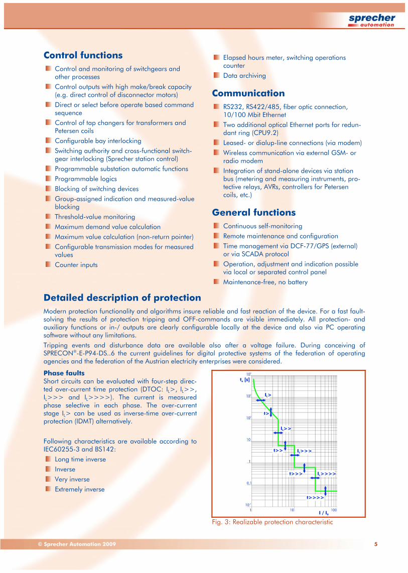
Phase faults Short circuits can be evaluated with four-step direc-ted over-current time protection (DTOC: IL>, IL>>, IL>>> and IL>>>>). The current is measured phase selective in each phase. The over-current stage IL> can be used as inverse-time over-current protection (IDMT) alternatively. Following characteristics are available according to IEC60255-3 and BS142:
Long time inverse Inverse Very inverse Extremely inverse
Fig. 3: Realizable protection characteristic

6 www.sprecher-automation.com
Phase Preference at double earth-faults At double Earth-faults in insulated or compensated power systems it can be meaningful to switch off only one base point of the earth-fault. To obtain this a temporal phase preference is implemented.
Earth-fault treatment Besides the three phase currents the earth current can be monitored in four steps (IE>, IE>>, IE>>> and IE>>>>) for over-range of adjusted thresholds. Also for the earth current monitoring the first stage can be operated as inverse-time over-current protection (IDMT). The optional available sensitive earth-current measurement is suitable for detection of very small currents which can occur during earth-faults in non-earthed power systems. A wattmetric direction detection of earth-faults is also available.
Earth-fault current stabilization For the first earth-starting stage IE> a stabilization of the operate value can be inserted. This can prevent unauthorized tripping for example due to transducer errors that develop during summation of the three phase currents.
Treatment of intermitting earth-faults Short-term and reiterative recurring earth-faults are reliable recognized in grounded systems and a selective tripping can be introduced.
Current annunciation stages For support of the management two warning stages for phase currents and a warning stage for the earth-current are available.
Switch-on-to-fault protection With the help of the switch-on-to-fault protection spurious stimulations of the protection due to inrush currents of loads can be avoided.
Direction decision This function delivers the direction of error location in the case of a tripping-stimulation. Forward direc-tion means thereby an error location toward load, reverse direction toward bus-bar. Following direction decisions are possible:
Direction decision during short circuit Direction decision during earth-fault in resonant earthed (NOSPE) power systems
Earth-fault direction Direction changes are possible during tripping stimulation phase just as switching between earth-fault and short circuit and reverse. If the voltage path is disturbed, no direction decision takes place. A special time grading can take effect instead of. For close-up faults with a collapse of the measured voltage a voltage buffer is applied.
Fig. 4: Direction decision
Inrush restraint via harmonics-monitoring With the help of harmonics-monitoring spurious-stimulations of the protection during switch-on of transformers can be avoided through evaluation of the second harmonics.
Fault localization For quick localization in case of fault a display of the distance to the fault-location is possible in the short report.
Automatic synchronizer This function enables automatic connecting of bi-laterally fed power systems only with fulfilled syn-chronism conditions.
Earth-fault detection and direction decision (option) In non-earthed-neutral systems the task is to recognize a single earth-fault and to declare the earth-faulted phase. As a feature the OFF-command can be issued optionally at simultaneous exceed of a “assessed“ power value. Furthermore the detection of the earth-fault direction is possible after enabling the corresponding function. The use of an SDLRE-automatic is also supported.
Trip-circuit supervision The permanent supervision of a current flowing through the trip-circuit can be realized via one or two inputs.
Circuit-breaker failure protection As a check of correct OFF-command execution by the circuit-breaker the current flow is monitored for dropping below a minimum operate value. Does this drop off not occur within a given time after the OFF-command, the circuit-breaker could not inter-rupt the current flow. Additionally an OFF-require-ment can be executed by further devices or from subordinated branches.
I Mess
UMess
X
R
interior angle
forward decision
reverse decision
directional line

7© Sprecher Automation 2009
Teleprotection procedure/signal comparison Goal is an assured tripping in the first-zone time if external information let detect the fault in the protected area. Different procedures for signal com-parison are available. For example a high-speed busbar protection can be realized with the reverse interlock function.
Motor protection Comprehensive protection of motors including re-closing lockout through monitoring of acceleration time (heavy starting), locked rotor, under-load and component temperatures.
Voltage-/ displacement voltage protection The device monitors the voltage within four levels. During overflow (two levels) or falling below (2 levels) the limits and expiration of time stages a message or tripping is initiated.
Frequency protection Four freely chosen frequency thresholds can be monitored for overflow and/or falling below the thresholds. After expiration of time stages mes-saging or tripping can be initiated.
Negative sequence protection Load unbalance protection is reasonable for pro-tection of operational equipment that is thermally stressed by that neg. seq. current component. Just as asymmetric faults can be recognized whose current are smaller than the maximum load current. For supervision of current unbalances two stages are integrated whereby the first stage can be operated as a dependent (IDMT) stage.
Auto-reclosure AR The device can be equipped with a three-pole AR. Up to five reclosures are possible whereby the first interrupt can be adjusted as short time interruption. A disabling of the breaker tripping signal is integ-rated when the OFF-command is not final.
Earth short-circuit fault direction decision In low-resistance earthed-neutral systems, the zero power direction decision can be used as back-up protection if the starts exist exclusively due to the earth fault current and the displacement voltage. Even in the case of short-time low-resistance neutral earthing (SDLRE), the earth fault direction is determined with a specific sub-function of this zero power direction decision.
Overload protection (thermal replica) The thermal level is calculated with a specific model and compared then with the operate values whereby the influence of the corresponding previous load is taken into account. Depending on the operational equipment different characteristics can be selected. An adjustable reclosing lockout can prevent a pre-mature reconnecting after overload.
Fig. 5: Overload protection
Temperature protection (optional) If a temperature acquisition module AI/PT100 is provided, temperature monitoring is possible via PT100 sensors, e.g. for ambient temperatures, winding temperatures and outlet temperatures. In the case of several measuring locations, the digi-tized temperatures can be combined for one tem-perature via the functions Minimum, Maximum or Mean Value. If the settings are exceeded, warnings and - once enabled - also TRIP commands are issued.
100%
80%
60%
40%
20%
0%Time
90%
Level ofoverload memory
begin of exceptional load
reclosing lockout (adjustable)
cooling phase
tripping
preload
heating phase
manual reclosing
reclosing allowed
warning level 1(adjustable)
warning level 2 (adjustable)
8 www.sprecher-automation.com
Check of measured values To prevent faulty tripping and other faulty reactions, the plausibility of incoming measured values can be monitored.
Change of characteristic sets The input of four characteristic sets is possible. The selection of the active set is possible locally, by means of substation control or via binary input. For example is a changeover isolated – grounded pos-sible.
Event logging For afterward analysis of the activities the events are recorded chronologically arranged. Structuring events in groups, type of events and causes improves the clarity substantially.
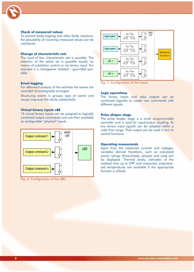
Virtual binary inputs vBE 15 virtual binary inputs can be assigned to logically combined output commands and are then available as configurable “physical“ inputs.
Fig. 6: Configuration of the vBEs
Fig. 7: Configuration of the inputs
Logic operations The binary inputs and relay outputs can be combined logically to create new commands with different signals.
Pulse shaper stage The pulse shaper stage is a small programmable controller and is used for input/output coupling. Its two binary input signals can be adapted within a wide time range. Their output can be used in turn to control functions.
Operating measurands Apart from the measured currents and voltages, variables derived therefrom, such as calculated power ratings (three-phase, phases) and cosϕ can be displayed. Thermal levels, estimates of the residual time up to OFF and measured, preproces-sed temperatures are available if the appropriate function is utilized.
AND OR
Output command 1
Output command n
Output command 2 vBE
AND OR
Softwarefunction
Optocoupler 1ton / toff
Optocoupler xton / toff
vBE 1 ton / toff
vBE n ton / toff

9© Sprecher Automation 2009
Disturbance data logging Additionally to event recording the disturbance data logging offers the possibility of later analysis of power system behavior. The disturbance data log-ging contains thereby storage of binary instant-aneous values of the measured values and impor-tant reactions of the device (stimulation, tripping). Several recordings can be saved to an overall length of 15 seconds. The lead time can be up to four seconds.
Fig. 8: Disturbance data logging
Testing and start-up aids Ample testing and start-up aids, e.g. for output relays, inputs, test AR, test TRIP, loop measurands, thermal replica, earth fault test, telegram test enable the protection setting considerably.
PC operating software COMM-3 Although the protection functions of SPRECON®-E-P device are adjustable and selectable also without PC, the work is substantially facilitated by the operating software COMM-3. Apart from device set-tings also measured values, events and disturbance data can be picked out and displayed. This is possible either via serial- and Ethernet inter-faces or via modem line. Moreover, the protection setting integrates an access protection which enables presettings by higher-ran-king persons in charge (full access) and permits only explicitly enabled settings to be performed by other members of staff via partial access.
Fig. 9: Operating software COMM-3 Additionally, COMTRADE files can be generated out of the fault records to be displayed via suitable graphic software (e.g. SDA2). The setting is trans-ferred to numeric test equipment via an XML file.

10 www.sprecher-automation.com
Detailed description of control Control function Enables control and monitoring of most different switching devices and process components. Accor-ding to specific requirements, it is possible to operate and monitor circuit breakers, disconnectors, tap changers for transformers and Petersen coils, pumps and motors. Thereby, operating can be initiated through:
Local control unit Station- or remote control Free programmable digital inputs
The number of elements that can be controlled is only restricted by the number of available in-/ outputs. Following concepts of controlling are possible:
1-pole control 1½-pole control 2-pole control
Command processing Depending on variant of the switchgear drives different switchgear types with specific command processing are available:
Single commands: It can be selected between persistent and pulse command output whereby with the pulse command the relay contact is independently reset after a defined time.
Double commands: A separate output relay has to be actuated for closing- and opening com-mands.
Commands for direct disconnector motor selection: After selection of a certain switching device via a command output relay, operation is initiated through a internal power relay.
Switchgear interlockings They are issued with the integration of switching readiness and permissibility tests. Preceding tests before the output of a command are,
switching device ready for operation, SETPOINT VAL. = ACTUAL VAL., e.g. is the switching device already in the required position,
is another operation already active (double-operation interlocking),
was the command initiated at a switching-authorized level (control authority),
if the new switchgear condition corresponds to a valid field- and/or plant topology (interlocking condition fulfilled)?
After a switching command output, the regular mode of operation of each switching device is monitored and an alarm is generated when neces-sary.
Tap changer control This integrated control function enables control of tap changers through specific types of switching devices. The actual tap position can be captured via digital inputs by binary, BCD or Ghielmetti code and analog mA signals. Furthermore, the regular mode of operation can be ensured by monitoring of tap changer operating time.
Preprocessing of binary data The digital input data preprocessing offers extensive functionalities for preparation of the binary input data. The configuration can thereby be accomp-lished for each input separately.
Contact debouncing This feature is used for debouncing of signals from mechanical contacts. The debouncing period can be set individually.
Chatter blocking The chatter blocking feature detects fault inputs, which show unstable status. In the case of perma-nent state changes the input is blocked for a determined time period in order to suppress unde-fined indication changes.
Signal filtering and delay Filtering serves to suppress brief changes in poten-tial at the digital input. The signal is only passed on if the signal voltage is present for a certain period of time. Additionally the digital signals can be delayed, which allows corrections of mechanical-related sig-nal sequences.
Signal generation After preprocessing digital input data, spontaneous single point information is generated in case of state changes. Supplementary, information on switching device states is generated in terms of double point information. Thus, additional information as switching device run, intermediate and fault conditions can be indicated besides defined on/off positions.
Metered values For internal metering the unit can calculate an energy metered value from the measured current- and voltage values. Additionally, functionalities as operating hours counter and switching operations counter are integrated. If an external meter with a metering pulse output is available, pulses can be captured and processed through digital inputs. All metered values are stored into a non-volatile memory and can be separately set and reset as well as monitored based on threshold-values.

11© Sprecher Automation 2009
Measured value acquisition / -processing in substation control For improved commissioning and management a wide range of functionalities for measured-value acquisition, preparation and transmission are available.
Operate value monitoring All measured and metered values can be monitored by using operate values. The operate value and possible time delays can be changed online . In the event of an out-of-range condition, an alarm is generated. For live-zero monitoring for detection of broken conductors normalized DC-signals of external measuring transducers can be processed.
Extended measured value characteristics (zoom-in function) Extending the range of measured values is sometimes requested when measuring transducers are in use. This, for example, applies to a frequency measurement of 45 to 55 Hz. Additional this func-tionality realizes a measured value zoom-in function by use of a non-linear characteristic curve.
Average value calculation Arithmetic mean values over a certain period of time can be calculated based on measured values, e.g. the 15 minute average.
Transmission modes Reduced data rates during the transmission of information to a SCADA system often leads to com-promises between quantity and up-to-dateness of data. Therefore different concepts for initiation of measured value transmissions can be applied:
Cyclic transmission Spontaneous transmission - Changing threshold with time-dependent switching criterion and/or - Additive operate value criterion
The transmission mode can be individually con-figured for each measured value.
Signal-/ measured value blocking To avoid the transmission of information to the master unit during tests of a feeder, transmission blocking can be activated. Groups of indication signals and measured values can be formed, whereas group-related transmission blocking can be carried out.
Signal derivation/grouping of signals/ summing up measured and metered values Further data points or commands can be derived from any data point (message, measured value) or count value. Also the summation of messages and measured values is supported, whereby the range of information is minimized for transmission to the SCADA system.
Programmable logic It acts as a tool to create specific solutions for the automation of bays or complete substation systems. Through combinations of signals in logic equations, user-specific indications can be de-fined and further actions can be derived.
Programmable automation functions In addition to programmable logic, it is possible to automate any required time sequence by means of programmable automation functions. For instance, sequences of commands like automatic bus-bar changeover in a double bus-bar system can be accomplished.
Event recording It enables continually archiving and storing of operationally relevant events in chronological order together with time stamps into a non-volatile memory.
Switching device blocking Blocking of the switching device prevents un-intentional operations during maintenance and inspection works on a switching device.
Control configuration All functionalities can be configured separately, whereby system configuration is separated from device-specific configuration. The concept of type orientation towards bay types is applied to the system configuration. Thereby, a complete system can be clearly configured using only one database. Concerning device-specific con-figuration, parameters like automatic synchronizer are set at device level, which makes an individual adaptation to various requirements possible. Furthermore, programmable logic allows realization of specific solutions in terms of bay or complete system automation. Adaptation of configurations can be carried out by means of local or remote maintenance.
Fig. 10: SPRECON®-E Designer

12 www.sprecher-automation.com
General functions
Continuous self-monitoring Comprehensive self-monitoring procedures within the device ensure that internal hardware or software errors are instantly detected in order to take ade-quate actions. This guarantees a high level of safety and reliability.
Time management Comprehensive self-monitoring procedures within the device ensure that internal hardware or software errors are instantly detected in order to take ade-quate actions. This guarantees a high level of safety and reliability.
Communication Various communication possibilities enable the integration into a substation control system of Sprecher Automation or different providers. Ad-ditional standalone devices like metering and measuring instruments, protective relays, voltage regulators, controllers for Petersen coils, etc. can also be integrated.
Ethernet For Ethernet LAN following variants are implemen-ted off the shelf:
CPU9.1: One electrical variant (RJ45, twisted pair)
CPU9.2/9.3: Integrated Ethernet switch with one electrical port (RJ45, twisted pair) and two optical ports (BFOC, fibre optic)
The last-mentioned CPU variant offers the imple-mentation of a redundant optical ring that maintains data flow after interruption. An overview of realized protocols can be found in the chapter “Technical Data”. Individual clarification can take place via further inquiry. Additionally a service interface is present. For remote service there is an optional connectivity for an external modem.
Serial connection Optional serial interfaces supporting asynchronous as well synchronous communication protocols are available in RS232-, RS422/485-standard or as fibre optic model:
CPU9.1: Two interfaces maximum CPU9.2: One interface maximum

13© Sprecher Automation 2009
Local operation With the help of the separated control panel all operations necessary for an efficient management can be carried out and information can be display-ed. The user interface convinces with functional and user friendly design. Process and device information can be full-graphi-cally shown on the back-lit and optional color LC display (7). Additionally there are 24 freely confi-gurable LEDs for indication and alarms (5).
They can be equipped with individually labeled marking pads (6). Separated navigation keys (2) allow clear user guidance through the various
pages as well as input of device configuration parameters. Further these keys are used to select the switching device. Subsequently, the essential switching operation is carried out via the separated control keys (3). Quick and safe changing of the different operating modes, e.g. selection of the switching authority, is achieved by use of the key-lock switch (4). Through separated status LEDs (1) the status of the control unit can be monitored. For a more detailed description of the detached control panel refer to the corresponding product description.
Fig. 11: Control panel with color display (CCP)

14 www.sprecher-automation.com
Technical data (1 of 4) General data
Mounting variants Surface-mounted case for wall installation with detached control panel see chapter Surface-mounted case for wall installation with attached control panel “Dimensions and mounting” Flush-mounted case for switchgear cabinets and control panels (attached control panel)
Mechanical characteristics dimensions see chapter “Dimensions and Mounting” connection see chapter “Connection Diagrams” degree of protection (acc. to IEC 60529) see chapter “Dimensions and Mounting” mass CU (40 HP) <6 kg (minimum assembly) CP/CCP <1 kg
Electrical terminals power supply COMBICON type GMSTB 2.5/3-ST-7.62 digital in-/ outputs, voltage transducer COMBICON type MSTB 2.5/...-ST-5.08 and COMBICON type MC1.5/...ST-3.5 wire size CT solid-/ stranded wire: 0.5 to 4 mm2 others solid-/ stranded wire: 0.2 to 2.5 mm2
communication interfaces see technical data 3 of 3, “Communication Interfaces”
Auxiliary power supply
Auxiliary voltage1 rated voltage Vaux 48 to 60 V DC 110 V DC and 220 V DC/AC, 230 V AC permitted tolerance -20 to +15 % power consumption 50 W max., fully assembled bridging time at supply failure of Vaux 110 to230 V DC ≥50 ms peak inrush current 110 to230 V DC <2 A
Digital inputs2
Rated voltage range Vi, aux input voltage variant Extended range 110 V 220 V DC rising operating point (L to H) 10 to 17 V 61 to 65 V 126 to 130 V DC falling operating point (H to L) 14.3 to 7.3 V 64.4 to 60.4 V 129.8 to 125.8 V permitted tolerance -20 to +15 % permitted capacitive coupling of inputs 100 nF
Digital outputs
Digital outputs (DO) max. switching voltage 250 V DC, 250 V AC max. contact continuous current 1 A max. making/breaking capacity 30 W/VA min. switching current approx. 500 mW (12 V, 10 mA) make time <7 ms typ.
Command outputs (CO) max. switching voltage 250 V DC, 250 V AC max. contact continuous current 5 A short-duration current 30 A for 0.5 s make time 7 ms typ. making capacity 1000 W/VA at L/R=40 ms breaking capacity 0.2 A at 220 V DC and L/R=40 ms3 4 A at 230 V AC and cosf=0.4
Power output P (PS/X1) max. switching voltage 230 V DC max. contact continuous current 10 A at 115 V DC or 5 A at 230 V DC max. making/breaking capacity 1150 W make time 15 ms typ. break time 8 ms typ.
1 other voltages on request 2 special implementation for series connection available 3 specific order option for inductive breaking capability
15© Sprecher Automation 2009
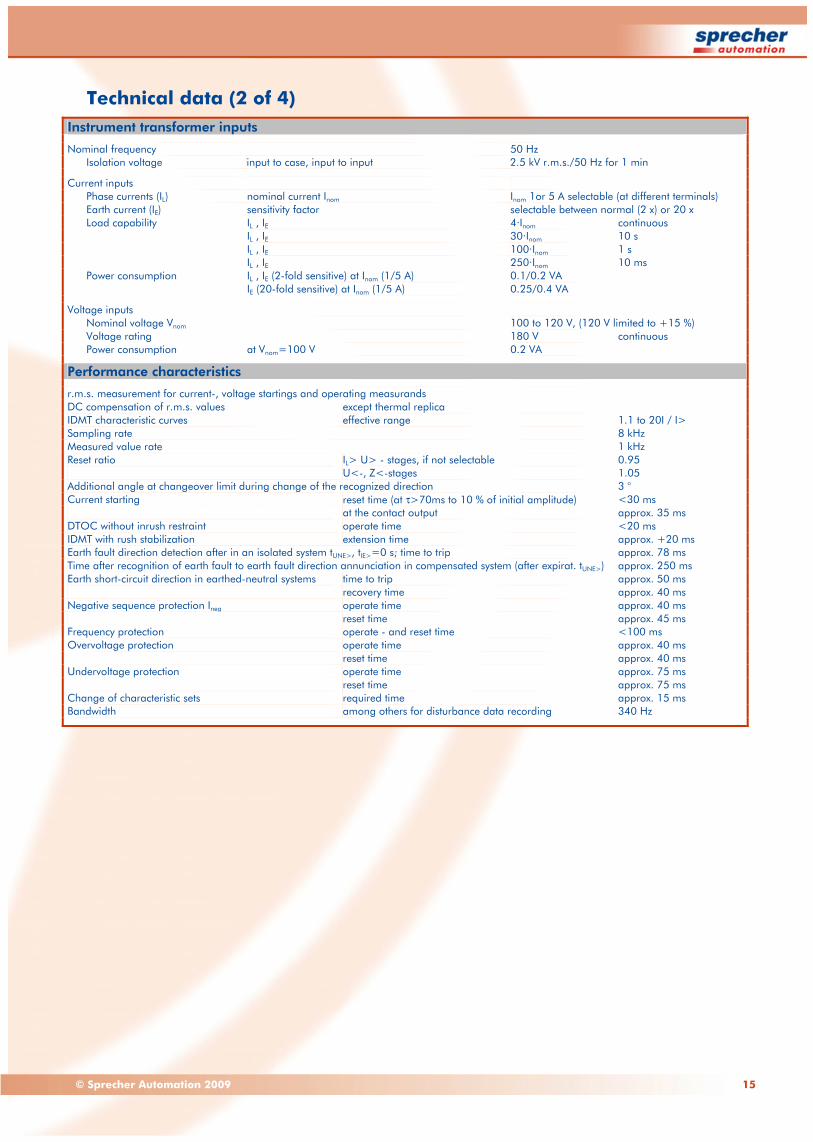
Technical data (2 of 4) Instrument transformer inputs
Nominal frequency 50 Hz Isolation voltage input to case, input to input 2.5 kV r.m.s./50 Hz for 1 min
Current inputs Phase currents (IL) nominal current Inom Inom 1or 5 A selectable (at different terminals) Earth current (IE) sensitivity factor selectable between normal (2 x) or 20 x Load capability IL , IE 4·Inom continuous IL , IE 30·Inom 10 s IL , IE 100·Inom 1 s IL , IE 250·Inom 10 ms Power consumption IL , IE (2-fold sensitive) at Inom (1/5 A) 0.1/0.2 VA IE (20-fold sensitive) at Inom (1/5 A) 0.25/0.4 VA
Voltage inputs Nominal voltage Vnom 100 to 120 V, (120 V limited to +15 %) Voltage rating 180 V continuous Power consumption at Vnom=100 V 0.2 VA
Performance characteristics
r.m.s. measurement for current-, voltage startings and operating measurands DC compensation of r.m.s. values except thermal replica IDMT characteristic curves effective range 1.1 to 20I / I> Sampling rate 8 kHz Measured value rate 1 kHz Reset ratio IL> U> - stages, if not selectable 0.95 U<-, Z<-stages 1.05 Additional angle at changeover limit during change of the recognized direction 3 ° Current starting reset time (at τ>70ms to 10 % of initial amplitude) <30 ms at the contact output approx. 35 ms DTOC without inrush restraint operate time <20 ms IDMT with rush stabilization extension time approx. +20 ms Earth fault direction detection after in an isolated system tUNE>, tIE>=0 s; time to trip approx. 78 ms Time after recognition of earth fault to earth fault direction annunciation in compensated system (after expirat. tUNE>) approx. 250 ms Earth short-circuit direction in earthed-neutral systems time to trip approx. 50 ms recovery time approx. 40 ms Negative sequence protection Ineg operate time approx. 40 ms reset time approx. 45 ms Frequency protection operate - and reset time <100 ms Overvoltage protection operate time approx. 40 ms reset time approx. 40 ms Undervoltage protection operate time approx. 75 ms reset time approx. 75 ms Change of characteristic sets required time approx. 15 ms Bandwidth among others for disturbance data recording 340 Hz

16 www.sprecher-automation.com
Technical data (3 of 4) Accuracy
Current stages detection threshold ≤2.5 % 0.01·Inom Load unbalanced protection (asymmetry failure protection) ≤3 % of phase currents IDMT characteristic w.r.t. time ≤5 % ±30 ms Determination of direction phase-angle error <3° Thermal replica w.r.t. threshold current ≤2.5 % Thermal replica w.r.t. time ≤5 % ±100 ms Fault location (homogen. line) for U > 2V, I > Inom, 30° < ϕK< 90° ≤5 % IE 20-fold sensitivity ≤3 %; 0.0005·Inom Voltage stages detection threshold ≤2,5 %; 0.01·Unom Calculated currents, voltages at nominal values (Inom, Unom) ≤5 % of measured value Frequency protection <10 mHz Intrinsic error secondary ±10 mΩ·A/Inom Time stages ≤0.5 % ±2 ms
Operating measurands
IL within 0.1 to 2·Inom 1 % of measured value + intrinsic error 0.5 % of Inom
IE measured 2 % or 1 mA
U within 0.1 to 1.2·Inom 1 % of measured value + intrinsic error 0.01 % of Unom
P, Q at U/Unom and I/Inom = 0.5 to 1.2 and |cosf|>0.7 2 % of Snom with Snom = √3·Unom·Inom
Influencing variables
Temperature -10° C to +55° C <1 % Harmonics 10 % <1 % Frequency 50 Hz ±5 % Current startings ≤3 % Operating measurands ≤3 % Direction detection ≤5° Thermal replica w.r.t. time <7.5 % IDMT characteristic <5 %
DC components Energizing an inductivity with maximum DC displacement (100 %) up to 30 ms after start <17 % after 30 ms <7.5 %

17© Sprecher Automation 2009
Technical data (4 of 4) Communication ports
Service interface CPU-located port for connection to a local maintenance PC on site RS232 RJ45 connector baud rate 38400 Baud isolation voltage 1.5 kV r.m.s.1 maximum distance 15 m
Interface to control panel CPU-located port for connection to separated control panel RS422/485 proprietary RJ45 connector baud rate 38400 Baud isolation voltage 1.5 kV r.m.s. maximum distance 10 m
Remote service interface2 service port located at the power supply module for modem connection RS232 9-pin D-SUB plug connector (male) baud rate 300 to 115200 Baud isolation voltage 1.5 kV r.m.s. maximum distance 15 m
System communication interfaces Depends on CPU two freely usable CPU-located ports possible protocol types synchronous and asynchronous interface type RS232, RS422/485, fiber-optic2
Ethernet-LAN CPU9.1 One electrical port CPU9.2, CPU9.3 Additionally two optical ports for redundant ring
Interface type
RS232 connector style 9-pin D-SUB plug connector (male) baud rate 300 to 115200 Baud isolation voltage 1.5 kV r.m.s. maximum distance 15 m
RS422/485 connector style 9-pin D-SUB jack connector (female) baud rate 300 to 115200 Baud or 375 KBaud system bus isolation voltage 1.5 kV r.m.s. maximum distance 1000 m at 38400 Baud
Optical plastic fiber on request
Optical glass fiber connector style BFOC-(ST®) /2,5 (F-SMA on request) fiber type Multi-mode graded index profile 50/125 μm, 62.5/125 μm Mono-mode step index profile 9/125 μm optical wavelength 820 to 860 nm maximum distance 4 km for 50/125 μm3
Ethernet connector style 1 x RJ45 plus 2 x BFOC (ST®) for LWL at CPU9.2 / CPU9.3 isolation voltage 1.5 kV r.m.s. bandwidth 10/100 MBit/s
Communication protocols
Uplink station bus protocols IEC 60870-5-101/104 IEC 61850 IED protocols IEC 60870-5-103 SPRECON® system bus Downlink IED protocols (max. 1 IED) IEC 60870-5-103 (in association with station bus only) Modbus
Time synchronization
External clock (RTC) Source external DCF-77- or GPS-clock Connection to any freely usable port Minute pulse Coupling via handshake line
via SCADA protocol recommended synchronization interval 1 min
Internal time management deviation with free running internal clock <1 min/ week
Time resolution real-time stamping 1 ms
1 galvanic isolation only for CPU9.2 / CPU9.3 2 depends on order variant 3 depends on quality and number of connectors

18 www.sprecher-automation.com
Tests (1 of 2) Safety tests (type test)
Electrical tests Verification of creepage distances and clearance IEC 60255-27
Voltage test IEC 60255-27 (60255-5) amplitude 2.5 kV rms frequency 50 Hz duration 1 min
Surge withstand capability test (SWC test) IEC 60255-27 (60255-5) amplitude 5 kV peak front time 1.2 μs time to half-value 50 μs
Insulation resistance after environmental test IEC 60255-27
Test of safety earth terminal IEC 60255-27 (IEC 60950)
Current transf. over-current withstand capability DIN VDE 0435-303 IL , IE (2-/ 20-fold sensitive) 100·Inom/1 s Current transf. rated peak withstand current DIN VDE 0435-303 250·Inom/10 ms
Output relays continuous-, make-/ break current IEC 60255-6
Flammability IEC 60255-27
Test of single faults IEC 60255-27
EMC tests (type test)
Emitted interference Radiated emission IEC 60255-25 30 to 230 MHz 40 dB(μV/m) 230 to 1000 MHz 47 dB(μV/m)
Conducted Emission (of auxiliary voltage) IEC 60255-25 0.15 to 0.50 MHz 79 dB(μV) quasi peak 66 dB(μV) average
IEC 60255-25 0.5 to 5 MHz 60 dB(μV) average 73 dB(μV) quasi peak
IEC 60255-25 5 to 30 MHz 60 dB(μV) average
Immunity to: 1 MHz Burst IEC 60255-22-1 frequency 1 MHz; 75 ns tR; common-mode amplitude 2.5 kV peak differential-mode amplitude 1 kV peak instrum. transf. 2.5 kV peak repetition rate 400 Hz
Electrostatic discharge (ESD) IEC 60255-22-2 contact discharge 6 kV air discharge 8 kV
Radiated electromagnetic field IEC 60255-22-3 frequency 80 MHz to 1000 MHz Amplitude 10 V/m; AM 1 kHz 80 %
Fast transient disturbance IEC 60255-22-4 class A tRise/tHold 5/50 ns amplitude 4 kV peak repetition rate 5 kHz
Current-, voltage surge IEC 60255-22-5 o.c. voltage tRise/tHold 1.2/50 μs s.c. current tRise/tHold 8/20 μs amplitude 0.5/1/2 kV
Conducted interference IEC 60255-22-6 frequency 150 kHz to 80 MHz; amplitude 10 V; AM 1 kHz 80 %
Line-frequency interference IEC 60255-22-7 common-mode amplitude 300 V coupling resistance 220 Ω coupling capacity 470 nF
class B differential-mode amplitude 100 V coupling resistance 100 Ω coupling capacity 47 nF
Auxiliary voltage (Vaux) Peak inrush current IEC 870-4 class S1 Interruption and depression IEC 60255-11 stored energy time >50 ms

19© Sprecher Automation 2009
Tests (2 of 2)
Environmental tests (type test)
Climatic tests Temperature IEC 60068-2-2 dry heat +70 °C/16 h (highest storage temperature) IEC 60068-2-1 dry cold -25 °C/16 h (lowest transport temperature)
Humidity IEC 60068-2-78 moist heat relative humidity 93 % at +40 °C/4 days
Cyclic temperature-humidity test IEC 60068-2-30
Vibration and shock Vibration test IEC 60255-21-1 stationary 10 to 150 Hz: 0.075 mm; 1.0 g transport 10 to 150 Hz: 2.0 g acceleration
Shock test IEC 60255-21-2 impulse duration 11 ms stationary 10 g acceleration transport 15 g acceleration
Seismic withstand capability IEC 60255-21-3 horizontal 1 to 8.5 Hz: 3.5 mm amplitude 8.5 to 35 Hz: 1.0 g acceleration vertical 1 to 8,5 Hz: 1.5 mm amplitude 8.5 to 35 Hz: 0.5 g acceleration
Sample tests
Safety test IEC 60255-27 High voltage test Inputs, outputs, communication interfaces amplitude 2.5 kV rms frequency 50 Hz duration 1 min Auxiliary voltage to ground amplitude 2.83 kV DC duration 1 min
Function check with secondary circuit tester
Temperature endurance test temperature +55 °C duration overall 24 h
Temperature cycle test temperature limit upper +55 °C lower +20 °C duration temperature cycle 4 h overall 72 h
Tolerated ambient conditions
Operation temperature range continuous operation -10 to +55 °C1 Storage temperature range -25 to +55 °C2 Transport temperature range -25 to +70 °C2
Relative humidity annual average <75 %, no condensation for 56 days <93 % at <40 °C, no condensation
The devices shall be arranged in such way that they are not exposed to direct sunlight or high changesin temperature that could cause condensation.
CE conformity
The „SPRECON®-E-P94-DS..6” series complies with Directive 2006/95/EC of the Council of the European Parliament and of the council of December 12th 2006 on the approximation of the laws of the Member States concerning electrical equipment for use within specified voltage limits (OJ L 374 of 2006-12-27) and Directive 2004/108/EC of the European Parliament and of the council of December 15th 2004 on the approximation of the laws of the Member States relating to electromagnetic compatibility and repealing Directive 89/336/EEC (OJ L 390 of 2004-12-31).
1 Control panel: 0 to +40 °C 2 Control panel: <48 h at -20 °C

20 www.sprecher-automation.com
Module plan
Fig. 12: Module plan
Connection diagrams
Fig. 13: Connection diagrams of the available modules
F F FZ Z Z Z S CP9
01 02 03 04 05 06 07 08 09 10
a b c d e f g h i j
Slot number
Slot
CPU9.1
CPU module
P9
Serial Port 11)
COM7
RS485
COM2
RJ45
RJ45
X5
X6
RS232
COM1
X2Serial Port 2 1)
COM8
Ethernet
RJ45 X4
RS232RS422/485fibre-optic
X1
RS232RS422/485fibre-optic
Control panel
Local service
LAN
CPU9.2
CPU module
P9
Serial Port 11)
COM7
RS485
COM2
RJ45
RJ45
X5
X6
RS232
COM1
X3
Ethernet
RJ45 X2
Ethernet
RS232RS422/485fibre-optic
X1
fibre-optic
LAN
Control panel
Local service
LAN
LAN
X4
Ethernet
fibre-optic
CPU9.3
CPU module
P9
RS485
COM2
RJ45
RJ45
X5
X6
RS232
COM1
X3
Ethernet
RJ45 X2
Ethernet
fibre-optic
LAN
Control panel
Local service
LAN
LAN
X4
Ethernet
fibre-optic
Ethernet
RJ45 X1LAN
Ethernet
RJ45 X7LAN
X10
PIN
X112
12
Command outputs
X2
12 X3
12 X4
12 X5
12 X6
12 X7
12 X8
12 X9
12
ITest
CO20
Command module
B
VI1+VI1-
VI2+VI2-
Option
CO 1.2CO 1.1
CO 2.2CO 2.1
CO 3.2CO 3.1
CO 4.2CO 4.1
CO 5.2CO 5.1
CO 6.2CO 6.1
CO 7.2CO 7.1
CO 8.2CO 8.1
CO 9.2CO 9.1
CO 10.2CO 10.1
X11
X1312
-
1
12
GRB
2
GRA
GND 3
X12
DIU10C4
Command module
C
-VI
-VI
-VI
-VI
-VI
-VI
-VI
-VI
-VI
-VI
Universal digital inputs
1
2
3
1
2
3
1
2
3
1
2
3
1
2
3
DI 7
DI 8
DI 5
DI 6
DI 3
DI 4
DI 1
DI 2
DI 9
DI 10
PIN
X7
X6
X5
X4
X3
Command outputs
CO 3
CO 4
1
2
3
4
6
5
X1
X2
CO 1
CO 2
1
2
3
4
6
5
-
-
-
-
-
-
-
-
DIU20
Univers.volt. digital input module
I
-
-
-
-
-
-
-
-
-
-
-
-
PIN
X1
Univers.volt. digital inputs
1
2
3
4
5DI 4 VI
DI 3 VI
DI 2 VI
DI 1 VI
1
2
3
4
5DI 8 VI
DI 7 VI
DI 6 VI
DI 5 VI
X2
1
2
3
4
5DI 12 VI
DI 11 VI
DI 10 VI
DI 9 VI
X3
2
3VI
DI 13 VI
X4DI 14
1
2
3VI
DI 15 VI
X5DI 16
1
2
3VI
DI 17 VI
X6DI 18
2
3VI
DI 19 VI
X7DI 20
1
1
DO20
Digital output module
O
PIN
X1
1
2
3
4
5
1
2
3
4
5
X2
1
2
3
4
5
X3
2
3
X4
1
2
3
X5
1
2
3
X6
2
3
X7
1
1
DO 4
DO 3
DO 2
DO 1
DO 8
DO 7
DO 6
DO 5
DO 12
DO 11
DO 10
DO 9
DO 14
DO 13
DO 16
DO 15
DO 18
DO 17
DO 20
DO 19
Digital outputs
21© Sprecher Automation 2009
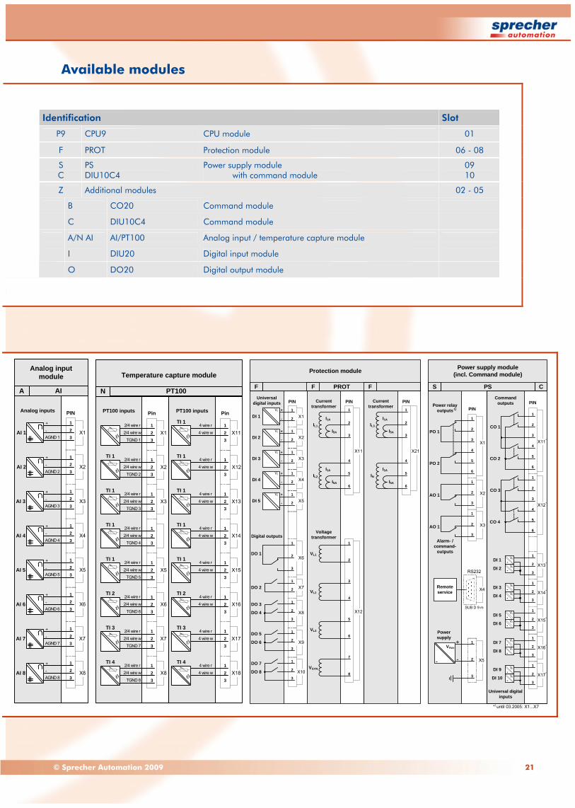
Available modules
Analog input module
AIA
AI 1
AI 2
AI 3
AI 4
AI 5
AI 6
AI 7
AI 8
+
-AGND 1
PIN
X2
1
X123
X4
X3
X6
X5
X8
X7
Analog inputs
+
-AGND 2
123
+
-AGND 3
123
+
-AGND 4
123
+
-AGND 5
123
+
-AGND 6
123
+
-AGND 7
123
+
-AGND 8
123
Platzh f. (vertikaleAusrichtung)
X2
X1
X3
X6
X5
X8
X7
PT100 inputs
123
123
123
123
X12
X11
X14
X13
X16
X15
X18
X17
PT100 inputs
123
123
123
123
ϑ
TI 1
ϑ
TI 1
TGND 5
ϑ
TI 2
ϑ
TI 2
TGND 6
ϑ
TI 3
ϑ
TI 3
TGND 7
ϑ
TI 4
ϑ
TI 4
TGND 8
123
123
ϑ
TI 1
ϑTGND 4
TI 1
123
123
ϑ
TI 1
ϑTGND 3
TI 1
123
123
ϑ
TI 1
ϑTGND 2
TI 1
123
4 wire r 123
ϑ ϑ4 wire w
2/4 wire r
2/4 wire w
TGND 1
TI 1
Temperature capture module
PT100N
Pin Pin
2/4 wire r
2/4 wire w
2/4 wire r
2/4 wire w
2/4 wire r
2/4 wire w
2/4 wire r
2/4 wire w
2/4 wire r
2/4 wire w
2/4 wire r
2/4 wire w
2/4 wire r
2/4 wire w
4 wire r
4 wire w
4 wire r
4 wire w
4 wire r
4 wire w
4 wire r
4 wire w
4 wire r
4 wire w
4 wire r
4 wire w
4 wire r
4 wire w
Platzh f. (vertikaleAusrichtung)
PIN
1+
DI 1 X1VI
- 2
1+
DI 2 X2VI
- 2
1+
DI 3 X3VI
- 2
1+
DI 4 X4VI
- 2
1+
DI 5 X5VI
- 2
1
2
3
X6
1
2
1
2
3
1
2
3
1
2
3
DO 1
X7
X8
X9
X10DO 8
DO 7
DO 6
DO 5
DO 4
DO 3
DO 2
Digital outputs
Universal digital inputs
Protection module
PROTF F F
X11
X12
PIN
1
2
3
I1A
IL1
I5A
4
5
6
I1A
I5A
IL2
1
2
3
4
5
6
7
8
VL3
VL2
VL1
VSYN
Voltage transformer
Current transformer
X21
PIN
1
2
3
I1A
I5A
4
5
6
I1A
I5A
IL3
IN
Current transformer
Platzh f. (vertikaleAusrichtung)
RS232
PIN
X14
5
6
1
2
3
3
2
1
X5
X4
X2
1
2
3
1
2
3
X3
Power supply
PO 1
PO 2
AO 1
AO 1
SUB D 9 m
Alarm- / command-
outputs
Remote service
Power relay outputs1)
+
--
VAux
PS
Power supply module(incl. Command module)
S C
X17*
X16*
X15*
X14*
X13*
X12*
X11*
1
2
3
4
6
5
1
2
3
PIN
1
2
3
1
2
3
1
2
3
1
2
3
1
2
3
4
6
5
CO 3
CO 4
DI 7
DI 8
DI 5
DI 6
DI 3
DI 4
DI 1
DI 2
CO 1
CO 2
DI 9
DI 10
Universal digital inputs
Command outputs
-VI
-VI
-VI
-VI
-VI
-VI
-VI
-VI
-VI
-VI
*) until 03.2005: X1...X7
Identification Slot
P9 CPU9 CPU module 01
F PROT Protection module 06 - 08
S C
PS DIU10C4
Power supply module with command module
09 10
Z Additional modules 02 - 05
B CO20 Command module
C DIU10C4 Command module
A/N AI AI/PT100 Analog input / temperature capture module
I DIU20 Digital input module
O DO20 Digital output module

22 www.sprecher-automation.com
Dimensions and mounting (1 of 3) The devices are suitable both for a wall assembly, and for the installation in switchgear cabinets and instrument panels.
In terms of surface mounting the control panel can be directly attached to the control unit with optional available fixing brackets.
Fig. 14: Overview of the mounting variants and IP degree of protection acc. to IEC 60529
Fig. 15: Control unit (CU) with 40 HP case, surface-mounted
94.2.046.44 94.2.046.4494.2.046.44
Surface-mounted central unitwith detached control panel
Flush-mounted central unitwith attached control panel
Surface-mounted central unitwith attached control panel
IP40
IP20
IP40
IP30/IP511)
IP20IP40
94.2.046.44 94.2.046.44 94.2.046.44
1) with seal kit at panel cutout (on request)
IP40
IP20
IP40
IP30/IP511)
IP20IP40
IP40
IP20
IP40
IP30/IP511)
IP20IP40
Mounting plate
Control unit
160 mm257 mm
176
mm
212 mm
200 mm
163
mm
M4
M4
M4
M4
LINKX4
CPU7
SERV
LAN1
CP
X6
R
TR
ACT
X5T
RT
T
LAN2
LINK
ACT
X3
X2
R
R
T R
X1
T
P7STAT
1
PS DIU10C4
X5
2X6
X72
3
1
23
13
X531
2
X2
T
X4
X3
R 2X3
X41
32
3
321
61
54
X2
X1
55
123
6123
6
X143
12
43
12
S CZZ Z Z
1
X331
10X 2
3
1X9
X8
2
23
PROT
5
78
6
2
43
1
21
1
1X7
X6
2
32
1
1
X5
X4
2X11
2
21
1X3
X2
2
2
1
109
X1
F
6
X21
3
5
4
2
1
F F
M4

23© Sprecher Automation 2009
Dimensions and mounting (2 of 3)
Fig. 16: Control unit t (CU) with attached hinged mounted control panel (CP)
2321/2572 mm 25 mm
Control panel
Control unit
Mounting plate
Hinged control panel
M4
M4
M4
M4
M4
M4
200 mm
163
mm
M4
25 mm
!
Control panelcan be hung uptemporarily
94.2.008.52-01/-021
94.2.008.53-01/-022
94.2.008.52-02194.2.008.52-011
94.2.008.52-01/-021
94.2.008.53-01/-022
94.2.008.52-01/-021
94.2.008.53-01/-022

24 www.sprecher-automation.com
Dimensions and mounting (3 of 3)
Fig. 17: Control unit (CU), flush-mounted with attached control panel (CP)
Fig. 18: Control unit (CU) with variable mounting brackets
Cabinet door
Control unit
Control panel
160 mm
257 mm
14 mm
100 mm
163
mm
Ø4.5 mm
4 mm
14 mm
100 mm
Ø18 mm
M4
M4
M4
M4
M4
1
PS DIU10C4
X5
2X6
X72
3
1
23
13
X531
2
X2
T
X4
X3
R2X3
X41
32
3
321
61
54
X2
X1
55
123
6
123
6
X143
12
43
12
S CZ
LIN K
X4
CPU9
SE
RV
LAN
1
CP
X6
R
T
R
AC T
X5T
RT
T
X2
R
R
T R
X1
T
P9STAT M4
M4
M6
M6
Position 1
Position 3
Position 2
24 TE: 159 mm / 40 TE: 240 mm / 84 TE: 464 mm
Position 1Position 2Position 3
24 HP: 159 mm / 40 HP: 240 mm / 84 HP: 464 mm
105
mm
60 mm
90 mm1
X331
10X 2
3
1X9
X8
2
23
PROT
5
78
6
2
43
1
21
1
1X7
X6
2
32
1
1
X5
X4
2X11
2
21
1X3
X2
2
2
1
109
X1
F
6
X21
3
5
4
2
1
F FZ
94.2.008.52-01/-021

25© Sprecher Automation 2009
Fig. 19: Detached control panel (CP) with drilling pattern
Ordering SPRECON®-E-P94-DS..6 The permanently updated and as well online available software tool SPRECON-E Configurator includes all components and all possible combinations for order selection. It offers following functionality based on assemblies / modules across devices to a complete system:
Configuration on the basis of: - Order assistance - Final documentation
SPRECON-E Configurator
Fig 20: SPRECON-E Configurator
25 mm
177
mm
222 mm
14 mm
100 mm
163
mm
Ø4.5 mm
4 mm
14 mm
100 mm
Ø18 mm
26 www.sprecher-automation.com
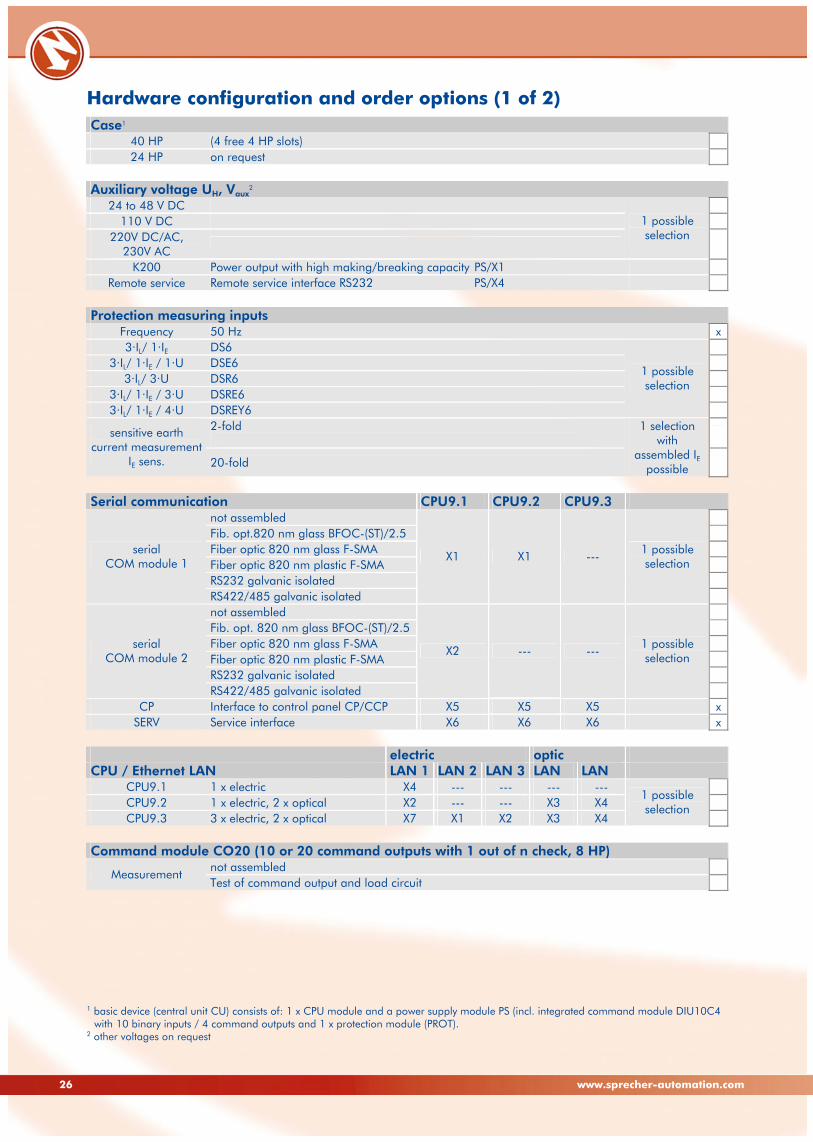
Hardware configuration and order options (1 of 2) Case1
40 HP (4 free 4 HP slots) 24 HP on request
Auxiliary voltage UH, Vaux
2 24 to 48 V DC
110 V DC 220V DC/AC,
230V AC
1 possible selection
K200 Power output with high making/breaking capacity PS/X1 Remote service Remote service interface RS232 PS/X4
Protection measuring inputs
Frequency 50 Hz x3·IL/ 1·IE DS6
3·IL/ 1·IE / 1·U DSE6 3·IL/ 3·U DSR6
3·IL/ 1·IE / 3·U DSRE6 3·IL/ 1·IE / 4·U DSREY6
1 possible selection
2-fold
sensitive earth current measurement
IE sens. 20-fold
1 selection with
assembled IE possible
Serial communication CPU9.1 CPU9.2 CPU9.3
not assembled Fib. opt.820 nm glass BFOC-(ST)/2.5 Fiber optic 820 nm glass F-SMA Fiber optic 820 nm plastic F-SMA RS232 galvanic isolated
serial COM module 1
RS422/485 galvanic isolated
X1 X1 --- 1 possible selection
not assembled Fib. opt. 820 nm glass BFOC-(ST)/2.5 Fiber optic 820 nm glass F-SMA Fiber optic 820 nm plastic F-SMA RS232 galvanic isolated
serial COM module 2
RS422/485 galvanic isolated
X2 --- --- 1 possible selection
CP Interface to control panel CP/CCP X5 X5 X5 x
SERV Service interface X6 X6 X6 x electric optic CPU / Ethernet LAN LAN 1 LAN 2 LAN 3 LAN LAN
CPU9.1 1 x electric X4 --- --- --- --- CPU9.2 1 x electric, 2 x optical X2 --- --- X3 X4 CPU9.3 3 x electric, 2 x optical X7 X1 X2 X3 X4
1 possible selection
Command module CO20 (10 or 20 command outputs with 1 out of n check, 8 HP)
not assembled Measurement
Test of command output and load circuit
1 basic device (central unit CU) consists of: 1 x CPU module and a power supply module PS (incl. integrated command module DIU10C4
with 10 binary inputs / 4 command outputs and 1 x protection module (PROT). 2 other voltages on request

27© Sprecher Automation 2009
Hardware configuration and order options (2 of 2) Command module DIU10C4 (10 binary inputs / 4 command outputs, 4 HP)
Universal 24 to 220 V DC, ↑10 -17 V / ↓14,3 - 7,3 V 110 V DC 65 to 220 V DC, ↑61 -65 V / ↓64,4 - 60,4 V 220 V DC 130 to 220 V DC, ↑126 -130 V / ↓130 - 126 V
multiple selection possible1
Digital input module DIU20 (20 binary inputs, 4 HP)
Universal 24 to 220 V DC, ↑10 -17 V / ↓14,3 - 7,3 V 110 V DC 65 to 220 V DC, ↑61 -65 V / ↓64,4 - 60,4 V 220 V DC 130 to 220 V DC, ↑126 -130 V / ↓130 - 126 V
multiple selection possible1
Digital output module DO20 (20 binary outputs, 4 HP)
Relay contacts 24 to 220 V DC and 110 to 230 V AC 50/60 Hz Analog input board AI / (4 or 8 analog inputs, 8 HP)
4 x PT100 inputs N
8 x PT100 inputs A/N 4 x mA-/ 4 x PT100 inputs
multiple selection possible1
Control panel CP/CCP (full graphics display, 24 free configurable LEDs
monochrome 320 x 240 pixels Display
4096 colors, 320 x 240 pixels 1 possible selection
Position 1-2-3 latching Keylock switch
Position 1-2 latching, 3 non latching 1 possible selection
Length 1 m STB360P-1 Length 2 m STB360P-2 Length 3 m STB360P-3 Length 5 m STB360P-5
Connection cable
Length 10 m STB360P-10
1 possible selection
COMM-3 operating software
7600 7601 7602 7603 7604
Device program for structure version (CD ROM) 1 possible selection
Managem. software CD ROM
SDA-2 Graphics program to display disturbance data (COMTRADE format) Communication protocols
Uplink (as IED "standalone" device) IEC 60870-5-103 without IED + IED IEC 60870-5-103 (for one IED max.)
Station bus IEC 60870-5-101
+ IED Modbus (for one IED max.)
1 possible selection
without IED + IED IEC 60870-5-103 (for one IED max.)
Station bus IEC 60870-5-104
+ IED Modbus (for one IED max.)
1 possible selection
without IED + IED IEC 60870-5-103 (for one IED max.)
Station bus SPRECON system
bus + IED Modbus (for one IED max.)
1 possible selection
1 pay attention to number o free slots!

94.2.910.55en E
© Sprecher Automation 2009 Sprecher Automation, the Sprecher Automation logo and any alternative version thereof are trademarks and service marks of Sprecher Automation. Other names mentioned, registered or not, are the property of their respective companies. Any liability regarding the correctness and completeness of information and/or specifications in the document is excluded. All rights are reserved to alter specifications, make modifications, or terminate models without prior notice. The specifications of a model may vary from country to country.
Sprecher Automation GmbHFranckstrasse 51
A-4018 LinzÖsterreich
Tel: +43 732 6908-0Fax: +43 732 6908-321
Ignaz-Köck-Straße 101210 WienÖsterreich
Tel: +43 732 6908-601Fax: +43 732 6908-5601
Sprecher Automation Deutschland GmbHMöllendorffstraße 47
10367 BerlinDeutschland
Tel: +49 30 6449241-70Fax: +49 30 6449241-99
Sprecher Automation Polska Sp z o.o.ul. Łączna 4
58-100 ŚwidnicaPolska
Tel: +48 74 85135-31Fax: +48 74 85135-32
Sprecher Automation spol. s r.o.Kopčianska 14
851-01 BratislavaSlowakei
Tel: +421 2 682055-00Fax: +421 2 682055-10
www.sprecher-automation.com