9300 Mobile Computer - CipherLab
160
Windows CE Mobile Computer 9300 Version 1.09
Transcript of 9300 Mobile Computer - CipherLab
Windows CE Mobile Computer
9300
Version 1.09

Copyright © 2009~2012 CIPHERLAB CO., LTD. All rights reserved
The software contains proprietary information of CIPHERLAB CO., LTD.; it is provided under a license agreement containing restrictions on use and disclosure and is also protected by copyright law. Reverse engineering of the software is prohibited.
Due to continued product development this information may change without notice. The information and intellectual property contained herein is confidential between CIPHERLAB and the client and remains the exclusive property of CIPHERLAB CO., LTD. If you find any problems in the documentation, please report them to us in writing. CIPHERLAB does not warrant that this document is error-free.
No part of this publication may be reproduced, stored in a retrieval system, or transmitted in any form or by any means, electronic, mechanical, photocopying, recording or otherwise without the prior written permission of CIPHERLAB CO., LTD.
For product consultancy and technical support, please contact your local sales representative. Also, you may visit our web site for more information.
The CipherLab logo is a registered trademark of CIPHERLAB CO., LTD.
All brand, product and service, and trademark names are the property of their registered owners.
The editorial use of these names is for identification as well as to the benefit of the owners, with no intention of infringement.
CIPHERLAB CO., LTD. Website: http://www.cipherlab.com
FOR USA
This equipment has been tested and found to comply with the limits for a Class B digital device, pursuant to Part 15 of the FCC Rules. These limits are designed to provide reasonable protection against harmful interference in a residential installation. This equipment generates, uses and can radiate radio frequency energy and, if not installed and used in accordance with the instructions, may cause harmful interference to radio communications. However, there is no guarantee that interference will not occur in a particular installation. If this equipment does cause harmful interference to radio or television reception, which can be determined by turning the equipment off and on, the user is encouraged to try to correct the interference by one or more of the following measures:
Reorient or relocate the receiving antenna.
Increase the separation between the equipment and receiver.
Connect the equipment into an outlet on a circuit different from that to which the receiver is connected.
Consult the dealer or an experienced radio/TV technician for help.
This device complies with Part 15 of the FCC Rules. Operation is subject to the following two conditions: (1) This device may not cause harmful interference, and (2) this device must accept any interference received, including interference that may cause undesired operation.
FOR CANADA
This digital apparatus does not exceed the Class B limits for radio noise emissions from digital apparatus as set out in the interference-causing equipment standard entitled "Digital Apparatus," ICES-003 of Industry Canada.
This device complies with Part 15 of the FCC Rules. Operation is subject to the following two conditions: (1) This device may not cause harmful interference, and (2) this device must accept any interference received, including interference that may cause undesired operation.
Cet appareil numerique respecte les limites de bruits radioelectriques applicables aux appareils numeriques de Classe B prescrites dans la norme sur le material brouilleur: "Appareils Numeriques," NMB-003 edictee par l'Industrie.
FOR HAND-HELD PRODUCT WITH RF FUNCTIONS
This equipment complies with FCC radiation exposure limits set forth for an uncontrolled environment. This equipment should be installed and operated with minimum distance 20 cm between the radiator & your body. It only operated in hand-held used.
IMPORTANT NOTICES
If you only transfer data to the host wirelessly, please keep the minimum distance 20 cm between machine & your body.
FOR PRODUCT WITH LASER
CAUTION
This laser component emits FDA / IEC Class 2 laser light at the exit port. Do not stare into beam.
SAFETY PRECAUTIONS
RISK OF EXPLOSION IF BATTERY IS REPLACED BY AN INCORRECT TYPE. DISPOSE OF USED BATTERIES ACCORDING TO THE INSTRUCTIONS.
The use of any batteries or charging devices, which are not originally sold or manufactured by CipherLab, will void your warranty and may cause damage to human body or the product itself.
DO NOT disassemble, incinerate or short circuit the battery.
DO NOT expose the scanner or the battery to any flammable sources.
For green-environment issue, it's important that batteries should be recycled in a proper way.
Under no circumstances, internal components are self-serviceable.
The charging and communication cradle uses an AC power adaptor. A socket outlet shall be installed near the equipment and shall be easily accessible. Make sure there is stable power supply for the mobile computer or its peripherals to operate properly.
CARE & MAINTENANCE
This mobile computer is intended for industrial use. The mobile computer is rated IP 64, however, it may do damage to the mobile computer when being exposed to extreme temperatures or soaked wet.
When the body of the mobile computer gets dirty, use a clean and wet cloth to wipe off the dust. DO NOT use/mix any bleach or cleaner. Always keep the LCD dry.
For a liquid crystal display (LCD) or touch screen, use a clean, non-abrasive, lint-free cloth to wipe dust off the screen. DO NOT use any pointed or sharp object to move against the surface.
If you want to put away the mobile computer for a period of time, download the collected data to a host computer, and then take out the battery pack. Store the mobile computer and battery pack separately.
When the mobile computer resumes its work, the main and backup batteries will take a certain time to become fully charged.
If you shall find the mobile computer malfunctioning, write down the specific scenario and consult your local sales representative.

Version Date Notes
1.09 Apr. 20, 2011 Modified: Remove AutoRun from microSD card
1.08 May 04, 2011 Modified: Inside the Package — Add item “LCD Protective Film”
Modified: 3.5 Upgrading OS Image — Procedures updated
Modified: Specifications — Power Adaptor for 4-Slot Battery Charger (6 V, 3.5 A)
1.07 Mar. 18, 2011 Modified: Important Notices — Add RF statement
1.06 Oct. 20, 2010 Modified: 3.1 Application Manager — UI updated
Modified: Appendix I~III — Add more GS1 DataBar symbologies
Modified: Appendix III — Move “Inter-Character Gap” under Codabar and Code 39, and add “ISBT Concatenation” and “ISBT Concatenation Redundancy” for 2D Imager
1.05 Mar. 29, 2010 Modified: Installing Battery — Battery cover must be in position for normal operation
1.04 Mar. 16, 2010 Modified: Using Cradle — Power receptacle on the cable connector is non-functional when using cradle
Modified: 1.7 Cradles — LED indicators description
1.03 Feb. 25, 2010 New: 5.1.1 Bluetooth Profiles Supported
Modified: Installing Battery — Procedures and illustration changed
1.02 Jan. 25, 2010 New: 3.5.3 USB Update
Modified: 2.1.1 Suspend Mode — Pressing SCAN key can turn on the mobile computer
Modified: 5.6.2 Bluetooth ActiveSync — Bluetooth configuration for the computer
Modified: 6.4 Notifications (For Good Read)
Modified: 7.1.4 Using Backups for Restore — Remove version info
Modified: Specification — Working Time 12 hours w/o Wi-Fi
Modified: Appendix II Laser (SE955) — Redundancy Level, UPC/EAN Security Level, and GS1 DataBar (RSS) default settings
1.01 Oct. 29, 2009 Screenshots updated
1.00 Oct. 21, 2009 Initial release
RELEASE NOTES
CONTENTS
IMPORTANT NOTICES ...................................................................................................................... - 3 - For USA .......................................................................................................................................... - 3 - For Canada .................................................................................................................................... - 3 - For Hand-held Product with RF Functions ................................................................................... - 3 - For Product with Laser .................................................................................................................. - 4 - Safety Precautions ........................................................................................................................ - 4 - Care & Maintenance ..................................................................................................................... - 4 -
RELEASE NOTES .............................................................................................................................. - 5 -
INTRODUCTION .................................................................................................................................... 1 Features............................................................................................................................................. 2 Inside the Package............................................................................................................................ 3 Accessories........................................................................................................................................ 3
QUICK START ....................................................................................................................................... 5 Overview............................................................................................................................................. 5
Inserting Memory Card ................................................................................................................ 6 Connecting Headset..................................................................................................................... 6 Removing Hand Strap.................................................................................................................. 7 Installing Battery .......................................................................................................................... 8
Charging & Communications..........................................................................................................10 Using Wireless Networks ...........................................................................................................10 Using Cable.................................................................................................................................11 Using Cradle ...............................................................................................................................12
USING 9300 MOBILE COMPUTER.....................................................................................................13 1.1 Battery .......................................................................................................................................13
1.1.1 Understanding the Battery Icons.....................................................................................14 1.1.2 Power Management.........................................................................................................15
1.2 Memory .....................................................................................................................................16 1.2.1 Caution of Data Loss........................................................................................................16 1.2.2 Checking the Storage Space ...........................................................................................16
1.3 Keypad ......................................................................................................................................18 1.3.1 Keypad Settings ...............................................................................................................20 1.3.2 Alpha Key..........................................................................................................................20 1.3.3 Special Key .......................................................................................................................20 1.3.4 Function Key.....................................................................................................................21 1.3.5 Programmable Key...........................................................................................................21
1.4 Touch Screen ............................................................................................................................22 1.4.1 Adjusting the Backlight ....................................................................................................22 1.4.2 Re-calibrating the Screen ................................................................................................23
1.5 Notifications..............................................................................................................................24 1.5.1 Status LED ........................................................................................................................24
9300 Mobile Computer Reference Manual
1.5.2 Audio .................................................................................................................................24 1.5.3 Vibrator .............................................................................................................................24
1.6 Barcode Reader........................................................................................................................25 1.7 Cradles ......................................................................................................................................26
1.7.1 Charging & Communication Cradle.................................................................................26 1.7.2 Ethernet Cradle ................................................................................................................27
1.8 Battery Charger.........................................................................................................................28
LEARNING WINDOWS CE BASICS......................................................................................................29 2.1 Getting Started..........................................................................................................................30
2.1.1 Suspend Mode .................................................................................................................30 2.1.2 Desktop.............................................................................................................................31 2.1.3 Taskbar .............................................................................................................................32 2.1.4 Start Menu........................................................................................................................34 2.1.5 Input Methods ..................................................................................................................35
2.2 Managing Programs .................................................................................................................36 2.2.1 Quick Launch a Program .................................................................................................36 2.2.2 Switch among Programs and Desktop............................................................................36 2.2.3 Exit a Program ..................................................................................................................37
2.3 Using ActiveSync.......................................................................................................................38 2.3.1 Synchronization with Your Computer..............................................................................38 2.3.2 Add/Remove Programs....................................................................................................39 2.3.3 Explore Device..................................................................................................................40 2.3.4 Backup/Restore ...............................................................................................................41
2.4 Using Windows Explorer ...........................................................................................................42 2.4.1 Add a Program to Start Menu..........................................................................................42 2.4.2 Create a new Folder .........................................................................................................42
2.5 System Reset ............................................................................................................................43 2.5.1 Software Reset (Warm Reboot).......................................................................................43 2.5.2 Hardware Reset (Cold Reboot)........................................................................................43 2.5.3 Date/Time & Time Zone After Reset...............................................................................44
2.6 Auto Run....................................................................................................................................45
CONFIGURING 9300 MOBILE COMPUTER........................................................................................47 3.1 Application Manager ................................................................................................................47 3.2 Device Name & Configuration .................................................................................................48
3.2.1 Changing Device Name ...................................................................................................48 3.2.2 Understanding Device Configuration ..............................................................................49
3.3 System Settings ........................................................................................................................50 3.4 Connection Settings .................................................................................................................53 3.5 Upgrading OS Image.................................................................................................................55
3.5.1 OS version.........................................................................................................................55 3.5.2 SD Update.........................................................................................................................56 3.5.3 USB Update ......................................................................................................................57
USING 802.11 RADIO........................................................................................................................59 4.1 Turn On Wi-Fi Power .................................................................................................................59 4.2 Summit Client Utility .................................................................................................................60
4.2.1 Main Settings ...................................................................................................................60
9300 Mobile Computer Reference Manual
4.2.2 Profile Editing ...................................................................................................................64 4.2.3 Connection Status............................................................................................................69 4.2.4 Diagnostics .......................................................................................................................70 4.2.5 Global Settings .................................................................................................................73 4.2.6 Summit System Tray Icon ................................................................................................76
USING BLUETOOTH............................................................................................................................77 5.1 Turn on Bluetooth Power..........................................................................................................78
5.1.1 Bluetooth Profiles Supported ..........................................................................................79 5.1.2 Bluetooth Toolbar.............................................................................................................79 5.1.3 Set Discoverable ..............................................................................................................80
5.2 Search Devices .........................................................................................................................81 5.3 Pair Devices ..............................................................................................................................82
5.3.1 Identify Remote Device....................................................................................................82 5.3.2 Pair ....................................................................................................................................83 5.3.3 Unpair ...............................................................................................................................86
5.4 File Transfer ..............................................................................................................................87 5.4.1 Upload a File.....................................................................................................................87 5.4.2 Download a File................................................................................................................88
5.5 Object Push...............................................................................................................................89 5.6 Serial Port Service ....................................................................................................................90
5.6.1 Serial Port Service............................................................................................................90 5.6.2 Bluetooth ActiveSync .......................................................................................................92
5.7 Manage Local Services ............................................................................................................94 5.7.1 File Transfer......................................................................................................................94 5.7.2 Object Push ......................................................................................................................95 5.7.3 Serial Port Service............................................................................................................96
USING READER CONFIGURATION UTILITY.........................................................................................97 6.1 Run ReaderConfig.exe..............................................................................................................97 6.2 Barcode Reader Settings .........................................................................................................99 6.3 Data Output.............................................................................................................................100 6.4 Notifications (for Good Read) ................................................................................................102 6.5 Symbology Settings ................................................................................................................103
MORE APPLICATIONS ......................................................................................................................105 7.1 Backup Utility ..........................................................................................................................105
7.1.1 Managing the Registry ...................................................................................................106 7.1.2 Preparing for Backup .....................................................................................................107 7.1.3 Backing up Files .............................................................................................................108 7.1.4 Using Backups for Restore ............................................................................................110
7.2 Button Assignment Utility .......................................................................................................112 7.3 Screen Control ........................................................................................................................115
SPECIFICATIONS ..............................................................................................................................117 Platform, Processor & Memory.....................................................................................................117 Communications & Data Capture ................................................................................................117 Electrical Characteristics ..............................................................................................................118
9300 Mobile Computer Reference Manual
Physical Characteristics ................................................................................................................118 Environmental Characteristics .....................................................................................................119 Programming Support ...................................................................................................................119 Accessories....................................................................................................................................120
SCAN ENGINE SETTINGS.................................................................................................................121 Symbologies Supported ................................................................................................................121
LASER (SE955) ................................................................................................................................123 Reader Settings Table...................................................................................................................123 Symbology Settings Table.............................................................................................................124
Miscellaneous ..........................................................................................................................128 AIM Code ID – Code Characters..............................................................................................128 AIM Code ID – Modifier Characters.........................................................................................128
2D IMAGER ......................................................................................................................................131 Reader Settings Table...................................................................................................................131 Symbology Settings Table.............................................................................................................133
1D Symbologies .......................................................................................................................133 2D Symbologies .......................................................................................................................139 Image Capture & Miscellaneous .............................................................................................141 AIM Code ID – Code Characters..............................................................................................143 AIM Code ID – Modifier Characters.........................................................................................143
KEY REFERENCE TABLES ................................................................................................................147 29-key Keypad...............................................................................................................................147
Use of Alpha (α) / Function (fn)...............................................................................................148 43-key Keypad...............................................................................................................................149
Use of Alpha (α) / Function (fn)...............................................................................................150
1
9300 Mobile Computer, running Windows CE 6.0 in palm size, is our new product line of rugged PDA-style Mobile Computer. Compact, streamlined and ergonomic, it adds even more powerful and handy tools to delivering the flexibility in customization.
Specifically designed to work as an industrial PDA, 9300 Mobile Computer provides rich options of data collection, voice and data communications, long-lasting working hours, and so on. Its large color transflective TFT display guarantees ease in reading in all lighting conditions. Integrated with Bluetooth and 802.11b/g technologies, you can enjoy the convenience of wireless connection.
This manual serves to guide you through how to install, configure, and operate the mobile computer. The Care & Maintenance section is specifically prepared for those who are in charge of taking care of the mobile computer.
We recommend you to keep one copy of the manual at hand for quick reference or maintenance purposes. To avoid any improper disposal or operation, please read the manual thoroughly before use.
Thank you for choosing CipherLab products!
INTRODUCTION
2
9300 Mobile Computer Reference Manual
FEATURES
Ergonomic design - ruggedized yet streamlined, with hand strap for secure hold
Built tough to survive drop test and sealed against moisture/dust to industrial standard IP 64
Microsoft Windows CE 6.0 operating system, 624 MHz Marvell PXA310 processor
512 MB non-volatile NAND flash memory to store OS and software programs
(part of the free space is used as a storage card called DiskOnChip)
256 MB SDRAM to store and run programs, as well as store program data
One SD/MMC expansion slot for up to 32 GB memory card, and SDHC is supported
Two reader options — 1D laser scanner or 2D imager
Ambidextrous side triggers
Standard wireless solution — Bluetooth and IEEE 802.11b/g
A 2.8" color transflective TFT display delivers excellent visibility in lighting conditions
Programmable feedback includes buzzer, speaker and vibrator
Built-in power tools include Reader Configuration Utility, Backup Utility, etc.
Quick link to any backend database through MIRROR Emulator programs for VT100/220 and IBM 5250 emulation
Easy customization of data collection applications through FORGE Application Generator (AG) programs (AG*.exe for desktop PC)
Programming support includes System API (LIB and DLL) and Reader API (DLL)
Accessories and peripherals include international AC charging cradle and battery charger, etc.
3
Introduction
INSIDE THE PACKAGE
The following items are included in the package. Save the box and packaging material for future use in case you need to store or ship the mobile computer.
9300 Mobile Computer
Rechargeable Li-ion battery pack
Stylus
Hand Strap
USB charging & communication cable
Universal power adaptor
LCD Protective Film
Product CD
Quick Guide
ACCESSORIES
Rich choices of optional accessories are available for you to enhance the total performance of the mobile computer.
Protective Cover
Spare rechargeable Li-ion battery
4-slot Battery Charger
RS-232 charging & communication cable
USB host cable (for connecting external USB device)
Charging & Communication Cradle
Ethernet Cradle (10/100 BASE-T)
Vehicle Charger
Note: For 9300 as a data terminal equipment (DTE), the RS-232 charging & communication cable supports only CTS and RTS control signals. ActiveSync is not allowed.

4
9300 Mobile Computer Reference Manual
5
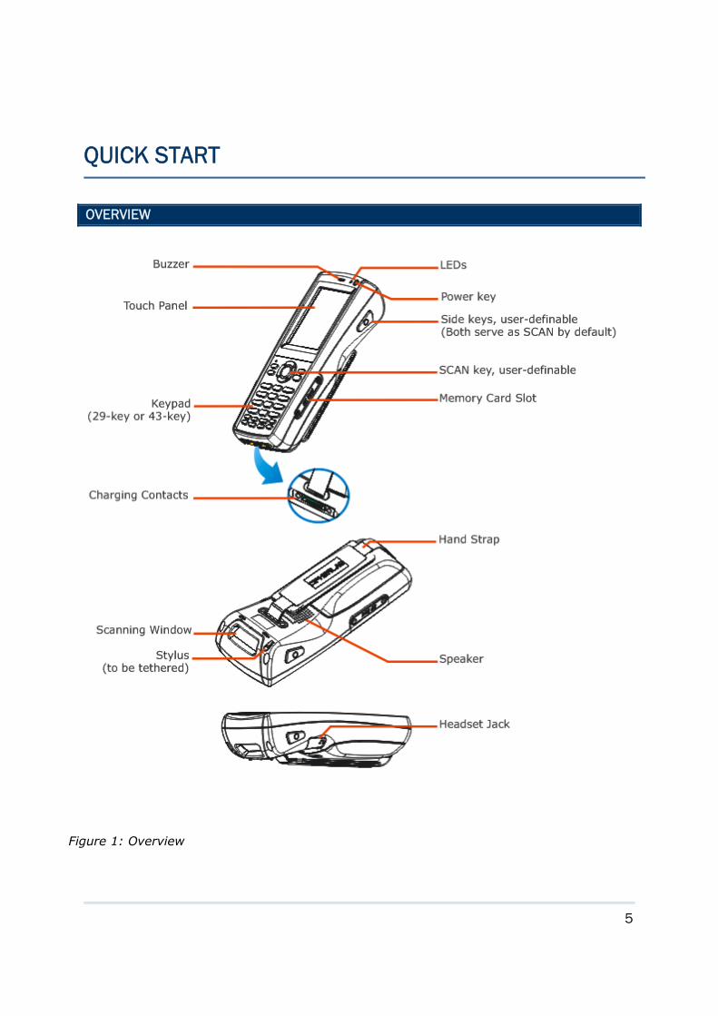
OVERVIEW
QUICK START
Figure 1: Overview
6
9300 Mobile Computer Reference Manual
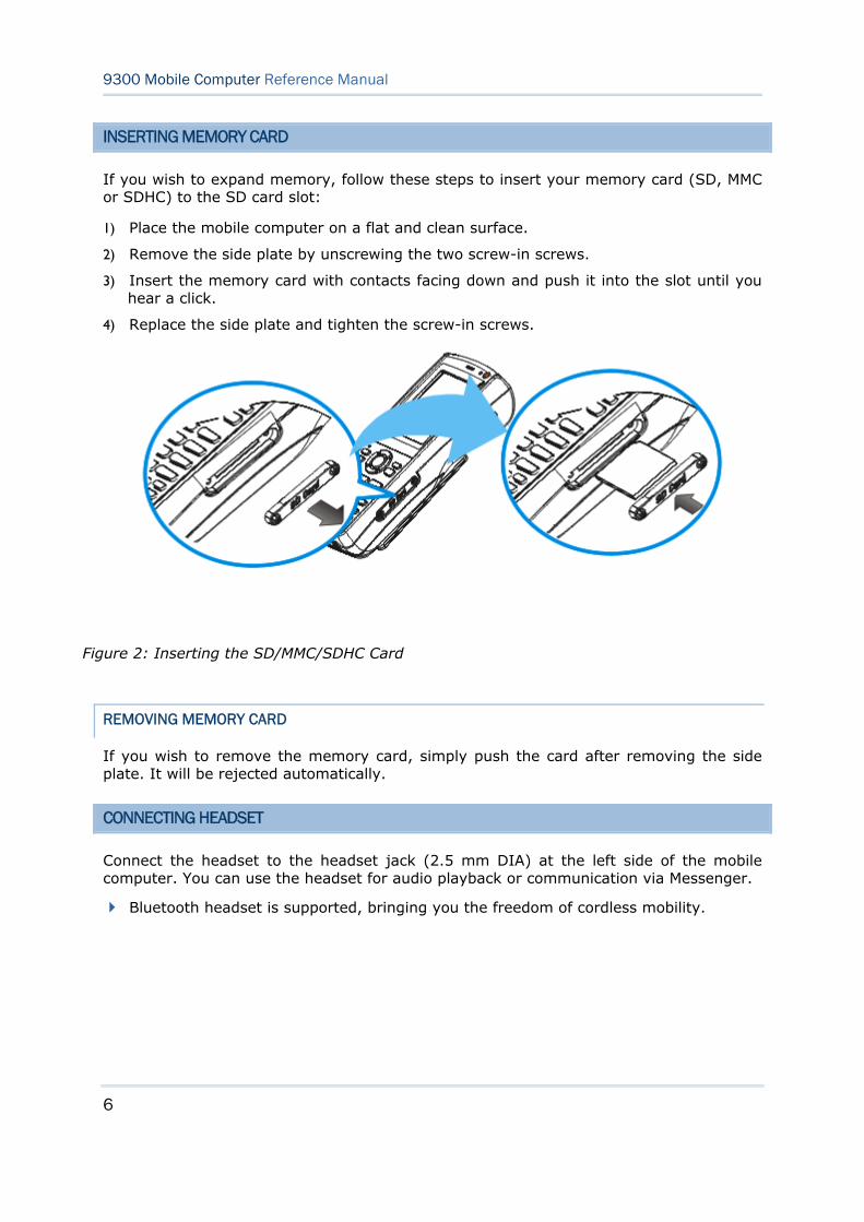
INSERTING MEMORY CARD
If you wish to expand memory, follow these steps to insert your memory card (SD, MMC or SDHC) to the SD card slot:
1) Place the mobile computer on a flat and clean surface.
2) Remove the side plate by unscrewing the two screw-in screws.
3) Insert the memory card with contacts facing down and push it into the slot until you hear a click.
4) Replace the side plate and tighten the screw-in screws.
REMOVING MEMORY CARD
If you wish to remove the memory card, simply push the card after removing the side plate. It will be rejected automatically.
CONNECTING HEADSET
Connect the headset to the headset jack (2.5 mm DIA) at the left side of the mobile computer. You can use the headset for audio playback or communication via Messenger.
Bluetooth headset is supported, bringing you the freedom of cordless mobility.
Figure 2: Inserting the SD/MMC/SDHC Card
7
Quick Start
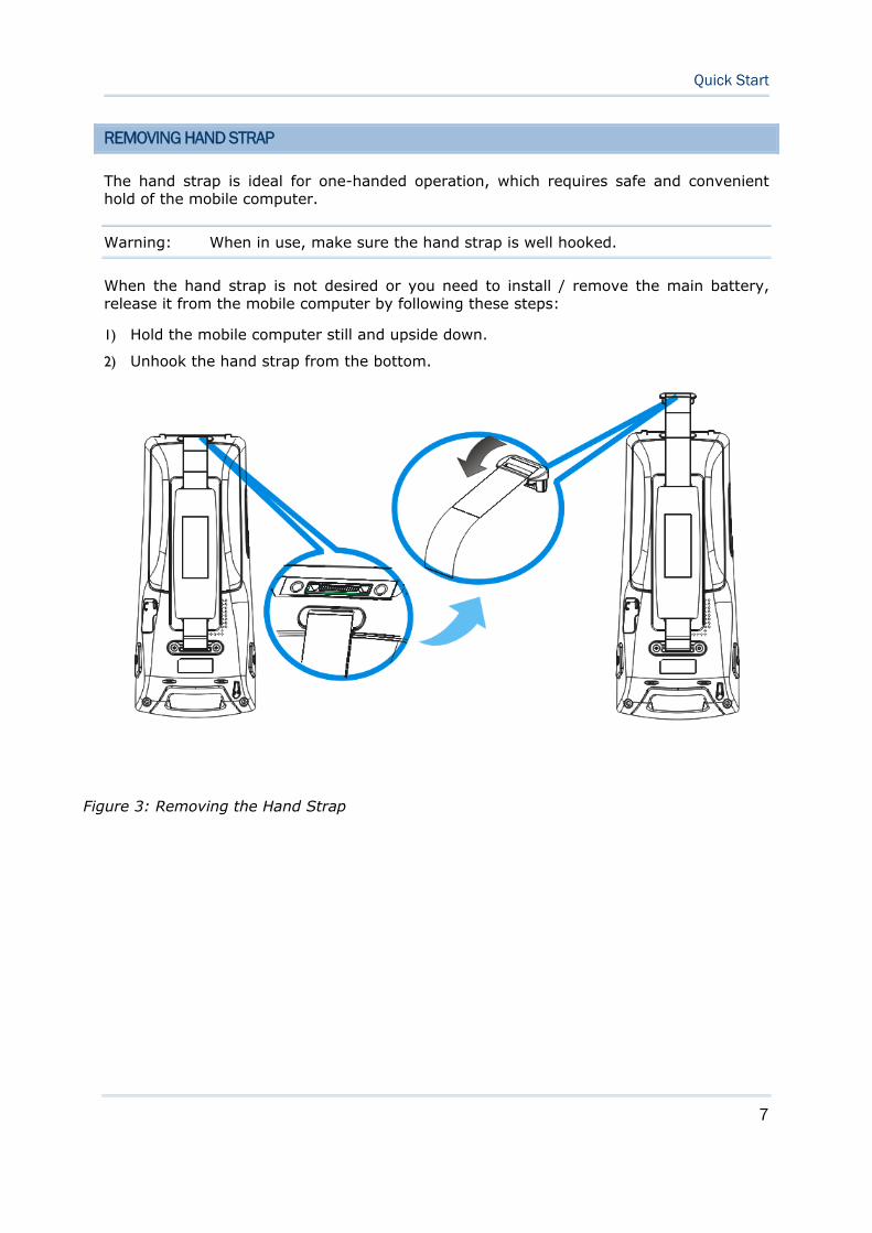
REMOVING HAND STRAP
The hand strap is ideal for one-handed operation, which requires safe and convenient hold of the mobile computer.
Warning: When in use, make sure the hand strap is well hooked.
When the hand strap is not desired or you need to install / remove the main battery, release it from the mobile computer by following these steps:
1) Hold the mobile computer still and upside down.
2) Unhook the hand strap from the bottom.
Figure 3: Removing the Hand Strap

8
9300 Mobile Computer Reference Manual
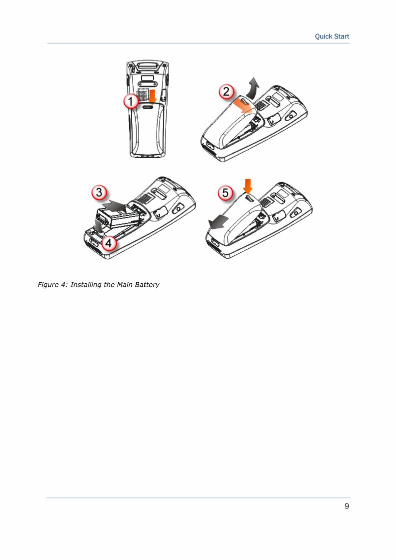
INSTALLING BATTERY
For shipping and storage purposes, the mobile computer and the main battery are saved in separate packages.
Note: Any improper handling may reduce the battery life. Release the hand strap from the mobile computer before installing the battery.
1) Hold the mobile computer still and press the release latch down.
2) Hold the release latch to the right and lift the battery cover away.
3) Insert the battery pack into the battery compartment at a proper angle (30°~45°) so that the metal contacts on the battery are met with the charging contacts inside the compartment.
4) Fit the battery snugly into the compartment.
5) Replace the battery cover and press the release latch down until it clicks into place.
6) If the battery is charged, the mobile computer turns on. If the mobile computer does not turn on, charge the battery.
Warning: The battery cover must be in position; otherwise, the mobile computer cannot turn on and operate normally.
9
Quick Start
Figure 4: Installing the Main Battery
10
9300 Mobile Computer Reference Manual
CHARGING & COMMUNICATIONS
The main and backup batteries may not be charged to full for shipment. When you first receive the package, you will need to charge the main battery to full before using the mobile computer. Instead of direct charging, you may use a cradle or charger to charge the Mobile Computer or spare batteries.
Because the internal backup battery is constantly charged from the main battery, the initial charging requires inserting the battery pack to the mobile computer and then connecting the mobile computer for direct charging or via cradle. This will have both the main and backup batteries charged at the same time.
Charging Time
Main battery: It takes approximately 4 hours to charge the main battery to full (from the adaptor). The LED above the screen is red while charging and will turn green when charging is done.
Backup battery: It takes at least 8 hours to charge the backup battery to full. The main battery must be inserted and left inside, whether the mobile computer is in use or not. However, it is not necessary to fully charge the backup battery for the mobile computer to work.
Charging Temperature
It is recommended to charge the battery at room temperature (18°C to 25°C) for optimal performance.
Battery charging stops when the temperature drops below 0°C or exceeds 40°C.
Operation on Battery Power
When 802.11b/g and BT are all enabled on battery power, the main battery charge will drop down substantially.
In order to prevent a cold boot after the battery is drained out, we suggest that you keep a fresh battery for replacement or connect the mobile computer to an external power.
USING WIRELESS NETWORKS
The mobile computer supports state-of-the-art wireless technologies, Bluetooth and 802.11b/g, so that it is able to send/receive data in real time in an efficient way.
11
Quick Start
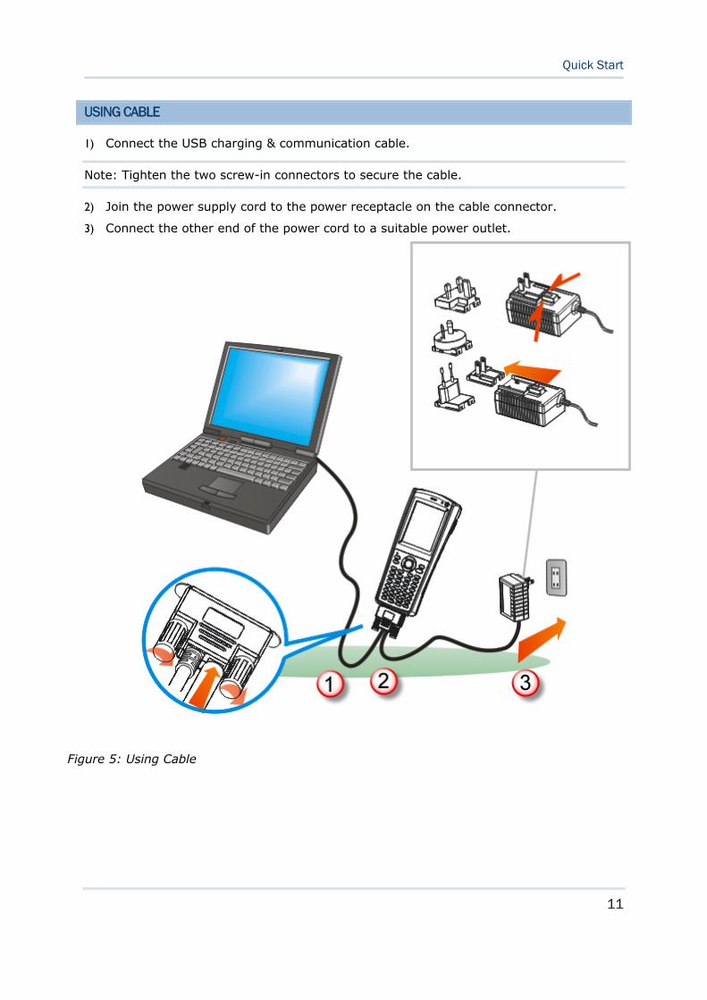
USING CABLE
1) Connect the USB charging & communication cable.
Note: Tighten the two screw-in connectors to secure the cable.
2) Join the power supply cord to the power receptacle on the cable connector.
3) Connect the other end of the power cord to a suitable power outlet.
Figure 5: Using Cable
12
9300 Mobile Computer Reference Manual
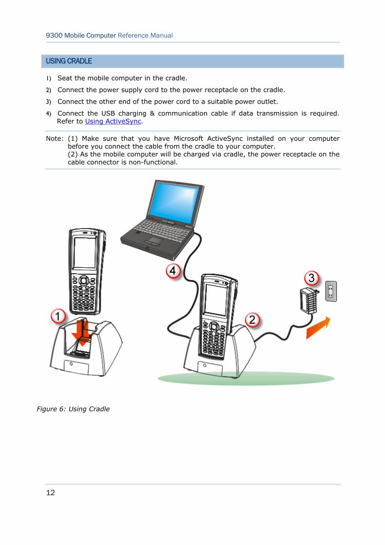
USING CRADLE
1) Seat the mobile computer in the cradle.
2) Connect the power supply cord to the power receptacle on the cradle.
3) Connect the other end of the power cord to a suitable power outlet.
4) Connect the USB charging & communication cable if data transmission is required. Refer to Using ActiveSync.
Note: (1) Make sure that you have Microsoft ActiveSync installed on your computer before you connect the cable from the cradle to your computer. (2) As the mobile computer will be charged via cradle, the power receptacle on the cable connector is non-functional.
Figure 6: Using Cradle
13
This chapter explains the features and usage of 9300 Mobile Computer.
IN THIS CHAPTER
1.1 Battery..................................................................... 13 1.2 Memory.................................................................... 16 1.3 Keypad..................................................................... 18 1.4 Touch Screen ............................................................ 22 1.5 Notifications.............................................................. 24 1.6 Barcode Reader ......................................................... 25 1.7 Cradles .................................................................... 26 1.8 Battery Charger......................................................... 28
1.1 BATTERY
Main Battery
9300 Mobile Computer is powered by a rechargeable 3.7 V/2700 mAh Li-ion battery pack, and it takes approximately 4 hours to fully charge it. However, the charging time may vary by working condition. During normal operation, the mobile computer can work for up to 10 hours.
Backup Battery
The backup battery on the main board takes charge when the main battery is removed or drained out. When fully charged, the 3.6 V/15 mAh rechargeable Ni-MH button cell helps retain data in SDRAM and maintain the system running in suspend mode for at least half an hour without the main battery. In the meantime, you have to replace the main battery as soon as possible.
Note: For a new battery, make sure it is fully charged before use. Always prepare a spare battery pack, especially when you are on the road.
Chapter 1 USING 9300 MOBILE COMPUTER
14
9300 Mobile Computer Reference Manual
1.1.1 UNDERSTANDING THE BATTERY ICONS
The battery pack is the only power source for the mobile computer to work. It also charges the backup battery on the main board so that the data stored in SDRAM can be retained properly. Therefore, when the main battery charge goes low, you need to replace the battery pack with a charged one or charge it as soon as possible. Most of all, you should backup important data on a regular basis.
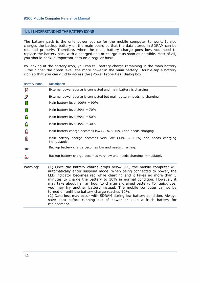
By looking at the battery icon, you can tell battery charge remaining in the main battery – the higher the green level, the more power in the main battery. Double-tap a battery icon so that you can quickly access the [Power Properties] dialog box.
Battery Icons Description
External power source is connected and main battery is charging
External power source is connected but main battery needs no charging
Main battery level 100% ~ 90%
Main battery level 89% ~ 70%
Main battery level 69% ~ 50%
Main battery level 49% ~ 30%
Main battery charge becomes low (29% ~ 15%) and needs charging
Main battery charge becomes very low (14% ~ 10%) and needs charging immediately.
Backup battery charge becomes low and needs charging.
Backup battery charge becomes very low and needs charging immediately.
Warning: (1) Once the battery charge drops below 9%, the mobile computer will automatically enter suspend mode. When being connected to power, the LED indicator becomes red while charging and it takes no more than 3 minutes to charge the battery to 10% in normal condition. However, it may take about half an hour to charge a drained battery. For quick use, you may try another battery instead. The mobile computer cannot be turned on until the battery charge reaches 10%. (2) Data loss may occur with SDRAM during low battery condition. Always save data before running out of power or keep a fresh battery for replacement.
15
Chapter 1 Using 9300 Mobile Computer
1.1.2 POWER MANAGEMENT
For any portable device, power management is a critical issue especially when you are on the road. Below are some tips to help you save battery power.
Warning: Using backlight, wireless connectivity, and peripherals while on battery power will substantially reduce battery power.
Bring a second battery pack on the road.
Stop wireless connectivity, Bluetooth or 802.11b/g that is not in use.
Go to Start | Settings | Control Panel and double-tap the Display icon. Refer to 1.4.1 Adjusting the Backlight.
Go to Start | Settings | Control Panel and double-tap the Power icon.
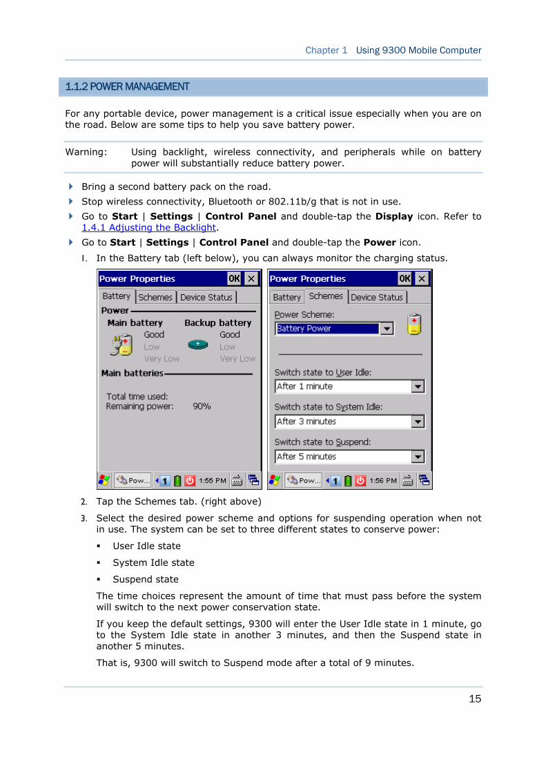
1. In the Battery tab (left below), you can always monitor the charging status.
2. Tap the Schemes tab. (right above)
3. Select the desired power scheme and options for suspending operation when not in use. The system can be set to three different states to conserve power:
User Idle state
System Idle state
Suspend state
The time choices represent the amount of time that must pass before the system will switch to the next power conservation state.
If you keep the default settings, 9300 will enter the User Idle state in 1 minute, go to the System Idle state in another 3 minutes, and then the Suspend state in another 5 minutes.
That is, 9300 will switch to Suspend mode after a total of 9 minutes.
16
9300 Mobile Computer Reference Manual
1.2 MEMORY
Flash Memory (ROM)
512 MB flash memory for storing OS (Windows CE 6.0) and custom application programs. Yet a portion of the memory is referred to as DiskOnChip, which can store data and programs that you wish to retain even after hardware reset.
Random-access Memory (RAM)
256 MB SDRAM for storing and running programs, as well as storing program data. Its contents will be retained by the backup battery.
Expansion Slot
The mobile computer is equipped with one SD/MMC card slot, which is user accessible. Up to 32 GB high capacity memory card (SDHC) is supported.
1.2.1 CAUTION OF DATA LOSS
When the main battery is removed or drained, the backup battery on the main board is to retain the contents of SDRAM and maintain the OS in suspend mode for at least 30 minutes, on condition that the backup battery has already been fully charged.
If you want to put away the mobile computer for a couple of days, you should be aware that data loss occurs when both the main and backup batteries discharge completely. Therefore, it is necessary to backup data and files before putting away the mobile computer!
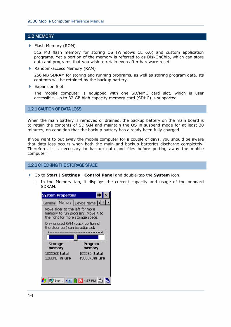
1.2.2 CHECKING THE STORAGE SPACE
Go to Start | Settings | Control Panel and double-tap the System icon.
1. In the Memory tab, it displays the current capacity and usage of the onboard SDRAM.
17
Chapter 1 Using 9300 Mobile Computer
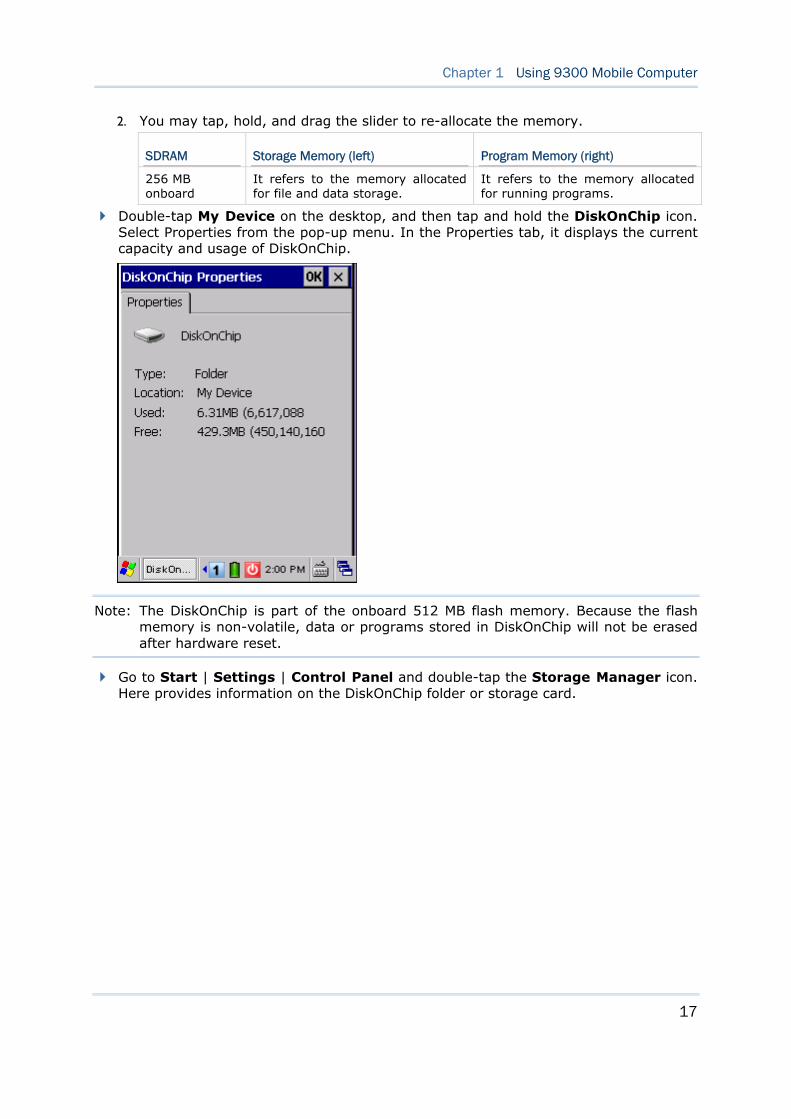
2. You may tap, hold, and drag the slider to re-allocate the memory.
SDRAM Storage Memory (left) Program Memory (right)
256 MB onboard
It refers to the memory allocated for file and data storage.
It refers to the memory allocated for running programs.
Double-tap My Device on the desktop, and then tap and hold the DiskOnChip icon. Select Properties from the pop-up menu. In the Properties tab, it displays the current capacity and usage of DiskOnChip.
Note: The DiskOnChip is part of the onboard 512 MB flash memory. Because the flash memory is non-volatile, data or programs stored in DiskOnChip will not be erased after hardware reset.
Go to Start | Settings | Control Panel and double-tap the Storage Manager icon. Here provides information on the DiskOnChip folder or storage card.
18
9300 Mobile Computer Reference Manual
1.3 KEYPAD
Silicon rubber has been chosen for their durability and prompt feedback.
Note: Functionality of keys is application-dependent.
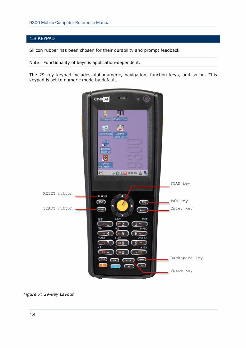
The 29-key keypad includes alphanumeric, navigation, function keys, and so on. This keypad is set to numeric mode by default.
Figure 7: 29-key Layout
SCAN key
Enter key
Backspace key
RESET button
Tab key
Space key
START button

19
Chapter 1 Using 9300 Mobile Computer
The 43-key keypad includes numeric, alphabetic, function and other modifier keys, as well as keys for navigation and assorted characters.
Figure 8: 43-key Layout
SCAN key
Tab key
Enter key
Backspace key
Space key
RESET button
START button
20
9300 Mobile Computer Reference Manual
1.3.1 KEYPAD SETTINGS
The LED backlight of keypad is turned off by default. Press to toggle it from off to on, and vice versa. It is suggested to turn on the keypad backlight while working in a dark area; however, using backlight while on battery power will substantially reduce battery power.
The Character Repeat functionality is enabled by default. Go to Start | Settings | Control Panel and double-tap the Keyboard icon. You may cancel the check box to disable it. When enabled, tap, hold, and drag the slider for a desired Repeat Delay and Repeat Rate.
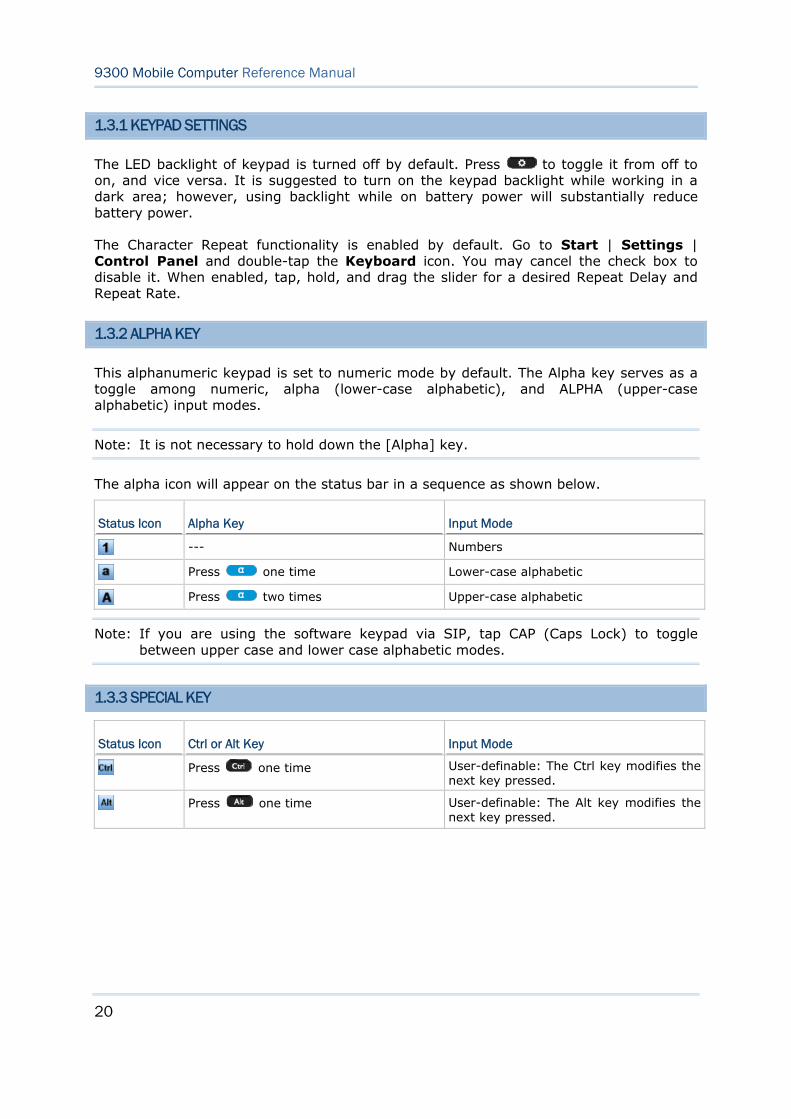
1.3.2 ALPHA KEY
This alphanumeric keypad is set to numeric mode by default. The Alpha key serves as a toggle among numeric, alpha (lower-case alphabetic), and ALPHA (upper-case alphabetic) input modes.
Note: It is not necessary to hold down the [Alpha] key.
The alpha icon will appear on the status bar in a sequence as shown below.
Status Icon Alpha Key Input Mode
--- Numbers
Press one time Lower-case alphabetic
Press two times Upper-case alphabetic
Note: If you are using the software keypad via SIP, tap CAP (Caps Lock) to toggle between upper case and lower case alphabetic modes.
1.3.3 SPECIAL KEY
Status Icon Ctrl or Alt Key Input Mode
Press one time User-definable: The Ctrl key modifies the next key pressed.
Press one time User-definable: The Alt key modifies the next key pressed.
21
Chapter 1 Using 9300 Mobile Computer
1.3.4 FUNCTION KEY
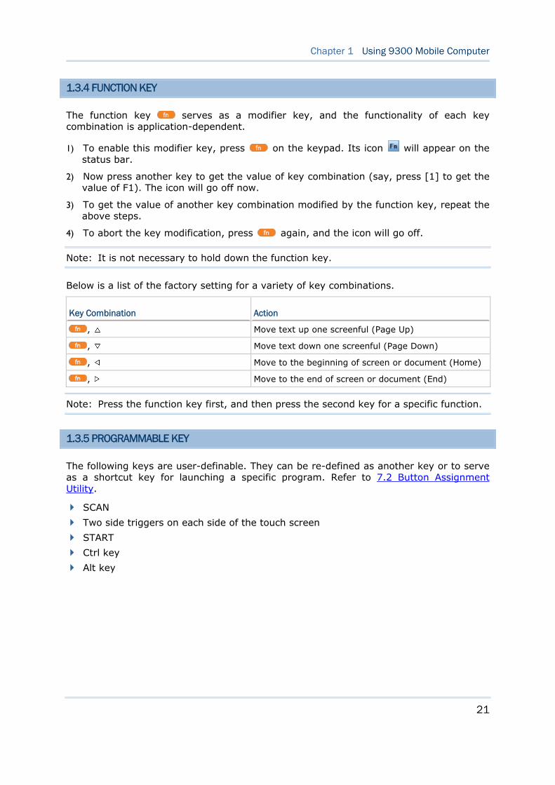
The function key serves as a modifier key, and the functionality of each key combination is application-dependent.
1) To enable this modifier key, press on the keypad. Its icon will appear on the status bar.
2) Now press another key to get the value of key combination (say, press [1] to get the value of F1). The icon will go off now.
3) To get the value of another key combination modified by the function key, repeat the above steps.
4) To abort the key modification, press again, and the icon will go off.
Note: It is not necessary to hold down the function key.
Below is a list of the factory setting for a variety of key combinations.
Key Combination Action
, Move text up one screenful (Page Up)
, Move text down one screenful (Page Down)
, Move to the beginning of screen or document (Home)
, Move to the end of screen or document (End)
Note: Press the function key first, and then press the second key for a specific function.
1.3.5 PROGRAMMABLE KEY
The following keys are user-definable. They can be re-defined as another key or to serve as a shortcut key for launching a specific program. Refer to 7.2 Button Assignment Utility.
SCAN
Two side triggers on each side of the touch screen
START
Ctrl key
Alt key
22
9300 Mobile Computer Reference Manual
1.4 TOUCH SCREEN
The mobile computer comes with a 2.8" TFT graphic LCD, 320 by 240 pixels resolution (QVGA). The LED backlight of screen, which helps ease reading under dim environments, can be controlled manually and automatically.
Warning: Using backlight while on battery power will substantially reduce battery power. It is suggested to dim the backlight while working in a well-lit area or automatically turn off the mobile computer when not in use.
1.4.1 ADJUSTING THE BACKLIGHT
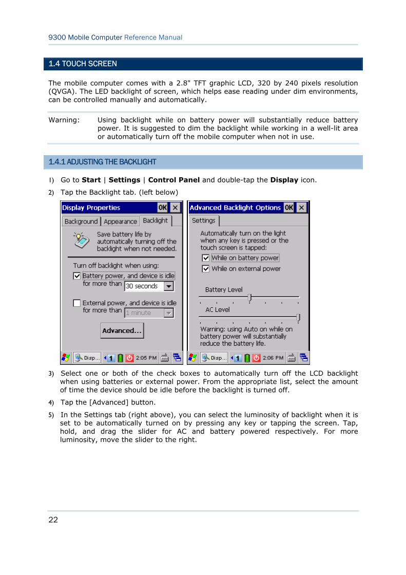
1) Go to Start | Settings | Control Panel and double-tap the Display icon.
2) Tap the Backlight tab. (left below)
3) Select one or both of the check boxes to automatically turn off the LCD backlight when using batteries or external power. From the appropriate list, select the amount of time the device should be idle before the backlight is turned off.
4) Tap the [Advanced] button.
5) In the Settings tab (right above), you can select the luminosity of backlight when it is set to be automatically turned on by pressing any key or tapping the screen. Tap, hold, and drag the slider for AC and battery powered respectively. For more luminosity, move the slider to the right.
23
Chapter 1 Using 9300 Mobile Computer
1.4.2 RE-CALIBRATING THE SCREEN
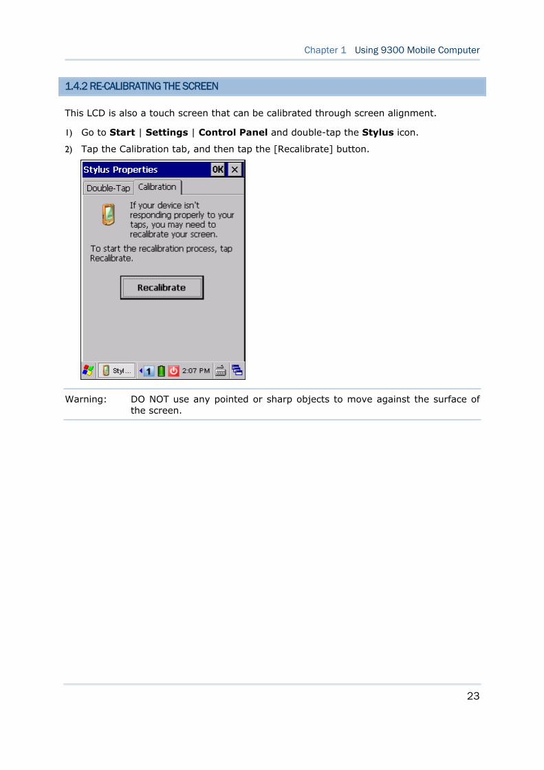
This LCD is also a touch screen that can be calibrated through screen alignment.
1) Go to Start | Settings | Control Panel and double-tap the Stylus icon.
2) Tap the Calibration tab, and then tap the [Recalibrate] button.
Warning: DO NOT use any pointed or sharp objects to move against the surface of the screen.
24
9300 Mobile Computer Reference Manual
1.5 NOTIFICATIONS
1.5.1 STATUS LED
The two dual-color LEDs on top are used to provide information on the charging status or wireless power status. The green LED is also used for "Good Read" while collecting data.
Charging LED (top right)
Tasks Green LED Red LED
Charging 9300 --- Solid
Charging done Solid ---
Good Read / Wireless LED (top left)
Tasks Green LED Blue LED
Good Read Solid for 0.5 second ---
Bluetooth enabled --- Flashing
1.5.2 AUDIO
Buzzer
The buzzer on the front can be programmed for status feedback. Its frequency and duration are software programmable.
Speaker
The mono speaker on the back is used to play sounds for events in Windows and programs, or play audio files such as .WAV files. In addition, it can be programmed for status feedback. In noisy environments, you may consider connecting a headset instead.
Headset
A headset jack is provided, which is a 2.5 mm DIA stereo earphone jack with microphone input. Bluetooth headset is also supported.
1.5.3 VIBRATOR
The mobile computer is integrated with a vibrator, which is software programmable for feedback. This can be helpful when working in noisy environments.

25
Chapter 1 Using 9300 Mobile Computer
1.6 BARCODE READER
Scan engines (1D laser scanner or 2D imager) are alternative for delivering flexibility to meet different requirements. Depending on the scan engine integrated, the mobile computer is capable of scanning barcodes of a number of symbologies that are enabled by default while running ReaderConfig.exe. If you need to scan barcodes that are encoded in a different symbology, enable the symbology first. Refer to Appendixes for details on scan engine settings.
Appendix I - Scan Engine Settings lists the symbologies supported.
Appendix II - Laser (SE955) provides information on the reader settings as well as symbology settings for the Laser scan engine.
Appendix III - 2D Imager provides information on the reader settings as well as symbology settings for the 2D scan engine.
26
9300 Mobile Computer Reference Manual
1.7 CRADLES
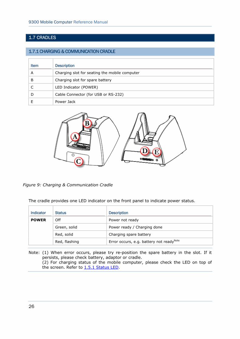
1.7.1 CHARGING & COMMUNICATION CRADLE
Item Description
A Charging slot for seating the mobile computer
B Charging slot for spare battery
C LED Indicator (POWER)
D Cable Connector (for USB or RS-232)
E Power Jack
The cradle provides one LED indicator on the front panel to indicate power status.
Indicator Status Description
Off Power not ready
Green, solid Power ready / Charging done
Red, solid Charging spare battery
POWER
Red, flashing Error occurs, e.g. battery not readyNote
Note: (1) When error occurs, please try re-position the spare battery in the slot. If it persists, please check battery, adaptor or cradle. (2) For charging status of the mobile computer, please check the LED on top of the screen. Refer to 1.5.1 Status LED.
Figure 9: Charging & Communication Cradle
27
Chapter 1 Using 9300 Mobile Computer
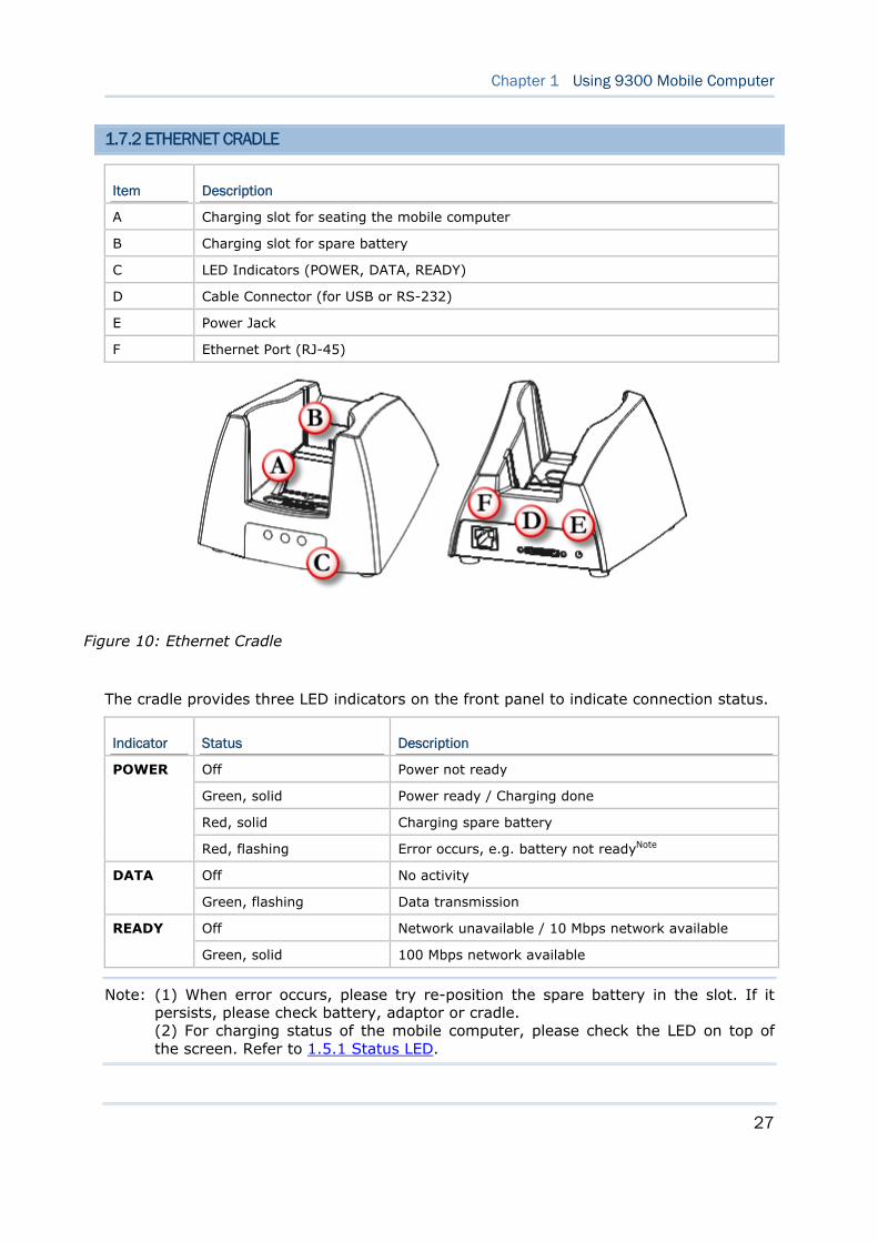
1.7.2 ETHERNET CRADLE
Item Description
A Charging slot for seating the mobile computer
B Charging slot for spare battery
C LED Indicators (POWER, DATA, READY)
D Cable Connector (for USB or RS-232)
E Power Jack
F Ethernet Port (RJ-45)
The cradle provides three LED indicators on the front panel to indicate connection status.
Indicator Status Description
Off Power not ready
Green, solid Power ready / Charging done
Red, solid Charging spare battery
POWER
Red, flashing Error occurs, e.g. battery not readyNote
Off No activity DATA
Green, flashing Data transmission
Off Network unavailable / 10 Mbps network available READY
Green, solid 100 Mbps network available
Note: (1) When error occurs, please try re-position the spare battery in the slot. If it persists, please check battery, adaptor or cradle. (2) For charging status of the mobile computer, please check the LED on top of the screen. Refer to 1.5.1 Status LED.
Figure 10: Ethernet Cradle
28
9300 Mobile Computer Reference Manual
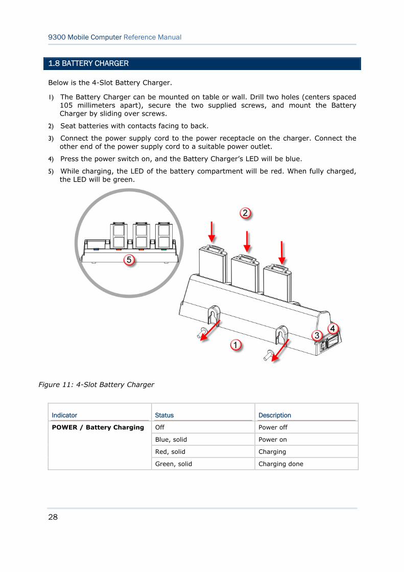
1.8 BATTERY CHARGER
Below is the 4-Slot Battery Charger.
1) The Battery Charger can be mounted on table or wall. Drill two holes (centers spaced 105 millimeters apart), secure the two supplied screws, and mount the Battery Charger by sliding over screws.
2) Seat batteries with contacts facing to back.
3) Connect the power supply cord to the power receptacle on the charger. Connect the other end of the power supply cord to a suitable power outlet.
4) Press the power switch on, and the Battery Charger’s LED will be blue.
5) While charging, the LED of the battery compartment will be red. When fully charged, the LED will be green.
Indicator Status Description
Off Power off
Blue, solid Power on
Red, solid Charging
POWER / Battery Charging
Green, solid Charging done
Figure 11: 4-Slot Battery Charger
29
This chapter mainly describes the basic skills to work with 9300 Mobile Computer. The add-on utilities for applications regarding data collection, processing, and transmission, are introduced in the following chapters.
9300 Mobile Computer is specifically designed for real-time data collection in the Windows CE 6.0 environment. It won't take long for any Windows user to get familiarized with it. Keep these basic skills in mind and explore this Windows CE device at ease.
Double-tap an item to select it.
Tap and hold an item to see a menu that enables tasks, such as cut, copy, rename, delete, etc.
Tap and drag to select multiple items.
Tap on the toolbar to close an active window, a dialog box, or a running application.
If the button is not displayed, press [ESC] on the physical keypad.
Tap on the toolbar to save the current settings and exit the application (or minimize the window in some applications).
If the button is not displayed, press [Enter] on the physical keypad.
IN THIS CHAPTER
2.1 Getting Started ......................................................... 30 2.2 Managing Programs ................................................... 36 2.3 Using ActiveSync ....................................................... 38 2.4 Using Windows Explorer.............................................. 42 2.5 System Reset............................................................ 43 2.6 Auto Run .................................................................. 45
Chapter 2 LEARNING WINDOWS CE BASICS
30
9300 Mobile Computer Reference Manual
2.1 GETTING STARTED
When 9300 Mobile Computer is fully charged, press for more than 1 second to turn on the mobile computer and wait for the Windows CE desktop to come up. If you are using the mobile computer for the first time, there are a couple of things to do after the desktop comes up.
To select your time zone and set the local time: Start | Settings | Control Panel and select Date/Time.
2.1.1 SUSPEND MODE
Like your PDA, Pocket PC and most handheld devices, 9300 Mobile Computer functions when it is turned on. This is because the Windows CE operating system eliminates the booting process and runs continuously.
Turn On (= Resume from Suspend)
Press for more than 1 second to turn on the mobile computer. Alternatively, you may press the SCAN key.
Turn Off (= Suspend)
Press for more than 1 second to turn off the mobile computer. Alternatively, you may select Suspend from the Start Menu.
The system is now ready for use but not in use. This is referred to as Suspend mode or Standby mode. It means the system is in power-saving status and waiting for user interference.
Warning: To save battery power, it is suggested that the mobile computer is set to be automatically turned off when not in use. Refer to 1.1.2 Power Management for more information about saving power.
31
Chapter 2 Learning Windows CE Basics
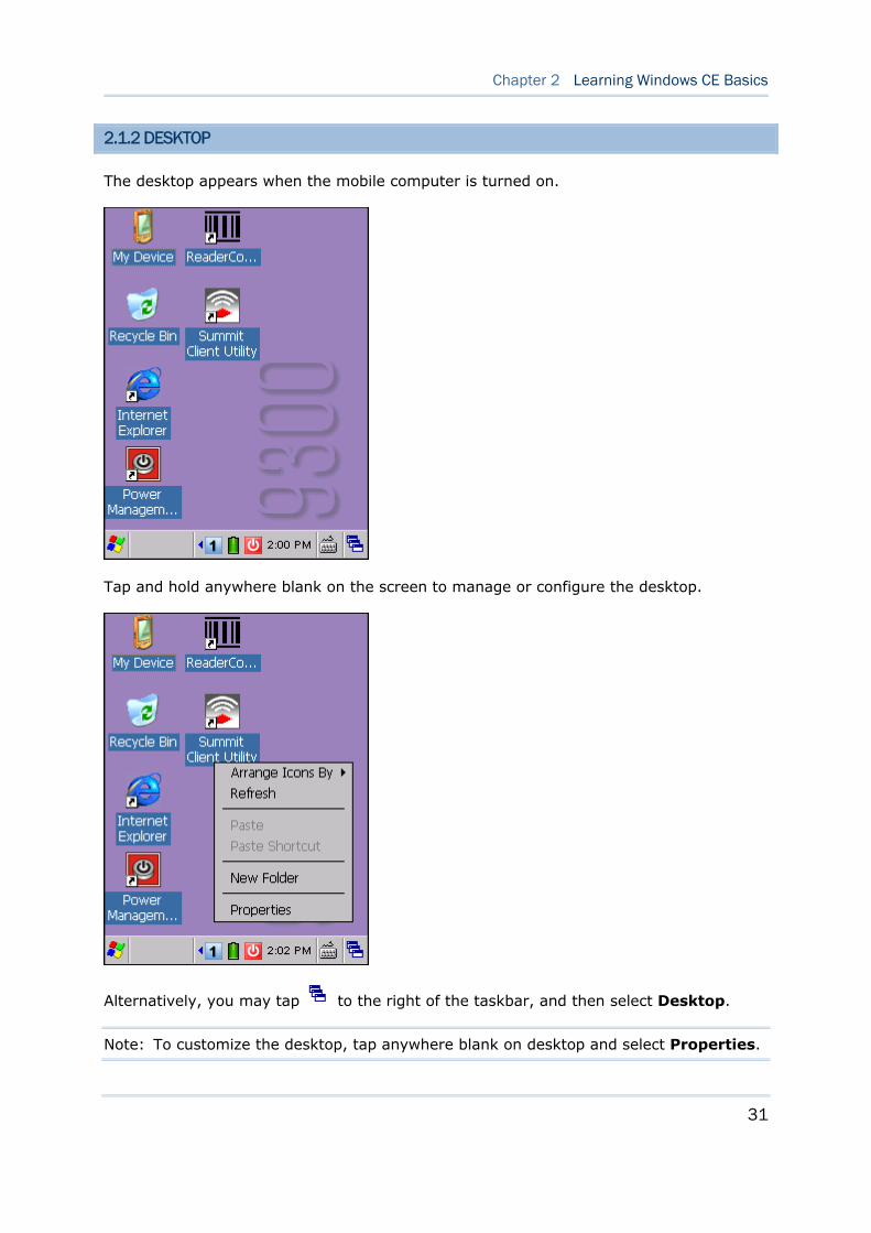
2.1.2 DESKTOP
The desktop appears when the mobile computer is turned on.
Tap and hold anywhere blank on the screen to manage or configure the desktop.
Alternatively, you may tap to the right of the taskbar, and then select Desktop.
Note: To customize the desktop, tap anywhere blank on desktop and select Properties.
32
9300 Mobile Computer Reference Manual
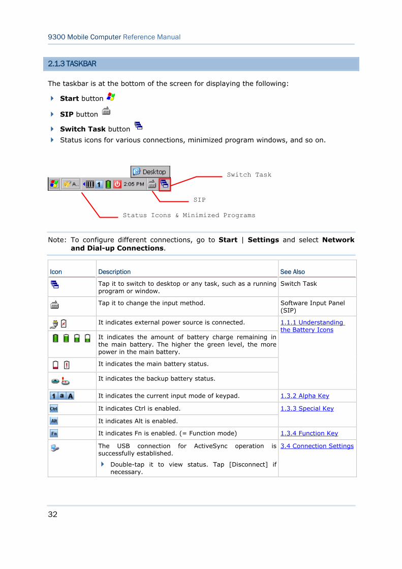
2.1.3 TASKBAR
The taskbar is at the bottom of the screen for displaying the following:
Start button
SIP button
Switch Task button
Status icons for various connections, minimized program windows, and so on.
Note: To configure different connections, go to Start | Settings and select Network and Dial-up Connections.
Icon Description See Also
Tap it to switch to desktop or any task, such as a running program or window.
Switch Task
Tap it to change the input method. Software Input Panel
(SIP)
It indicates external power source is connected.
It indicates the amount of battery charge remaining in the main battery. The higher the green level, the more power in the main battery.
It indicates the main battery status.
It indicates the backup battery status.
1.1.1 Understanding the Battery Icons
It indicates the current input mode of keypad. 1.3.2 Alpha Key
It indicates Ctrl is enabled.
It indicates Alt is enabled.
1.3.3 Special Key
It indicates Fn is enabled. (= Function mode) 1.3.4 Function Key
The USB connection for ActiveSync operation is successfully established.
Double-tap it to view status. Tap [Disconnect] if necessary.
3.4 Connection Settings
SIP
Switch Task
Status Icons & Minimized Programs
33
Chapter 2 Learning Windows CE Basics
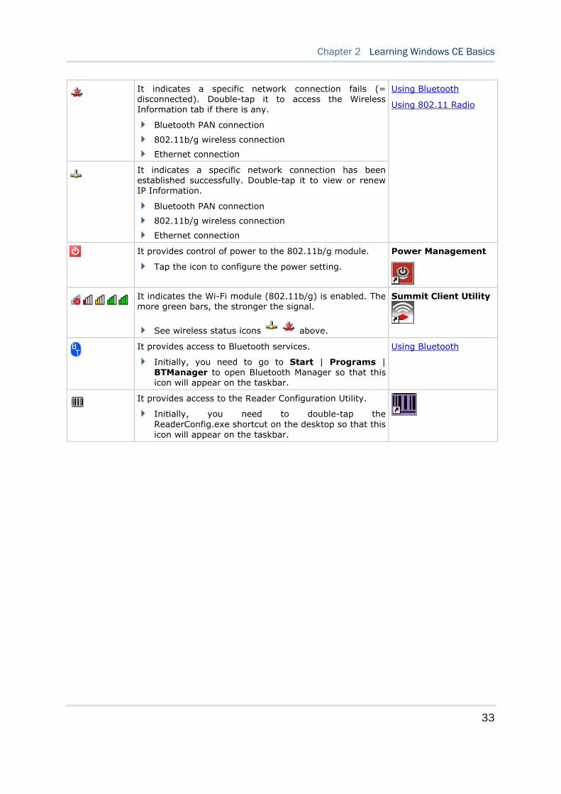
It indicates a specific network connection fails (= disconnected). Double-tap it to access the Wireless Information tab if there is any.
Bluetooth PAN connection
802.11b/g wireless connection
Ethernet connection
It indicates a specific network connection has been established successfully. Double-tap it to view or renew IP Information.
Bluetooth PAN connection
802.11b/g wireless connection
Ethernet connection
Using Bluetooth
Using 802.11 Radio
It provides control of power to the 802.11b/g module.
Tap the icon to configure the power setting.
Power Management
It indicates the Wi-Fi module (802.11b/g) is enabled. The more green bars, the stronger the signal.
See wireless status icons above.
Summit Client Utility
It provides access to Bluetooth services.
Initially, you need to go to Start | Programs | BTManager to open Bluetooth Manager so that this icon will appear on the taskbar.
Using Bluetooth
It provides access to the Reader Configuration Utility.
Initially, you need to double-tap the ReaderConfig.exe shortcut on the desktop so that this icon will appear on the taskbar.
34
9300 Mobile Computer Reference Manual
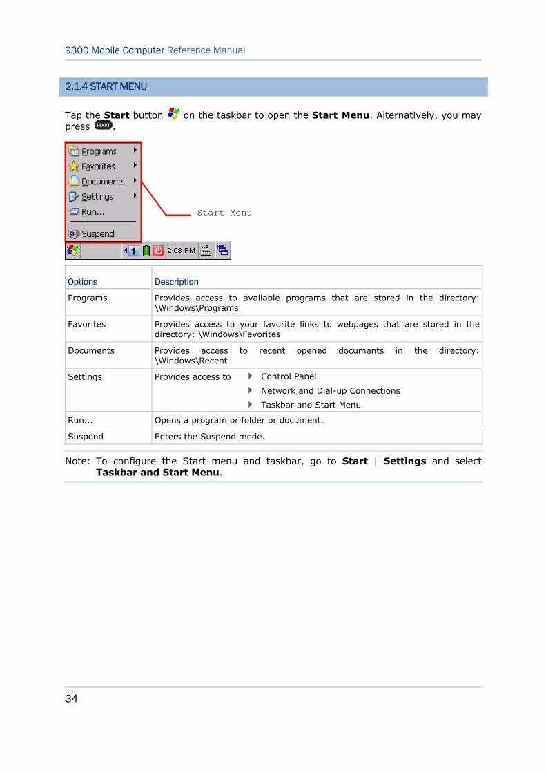
2.1.4 START MENU
Tap the Start button on the taskbar to open the Start Menu. Alternatively, you may press .
Options Description
Programs Provides access to available programs that are stored in the directory: \Windows\Programs
Favorites Provides access to your favorite links to webpages that are stored in the directory: \Windows\Favorites
Documents Provides access to recent opened documents in the directory: \Windows\Recent
Settings Provides access to Control Panel
Network and Dial-up Connections
Taskbar and Start Menu
Run... Opens a program or folder or document.
Suspend Enters the Suspend mode.
Note: To configure the Start menu and taskbar, go to Start | Settings and select Taskbar and Start Menu.
Start Menu
35
Chapter 2 Learning Windows CE Basics
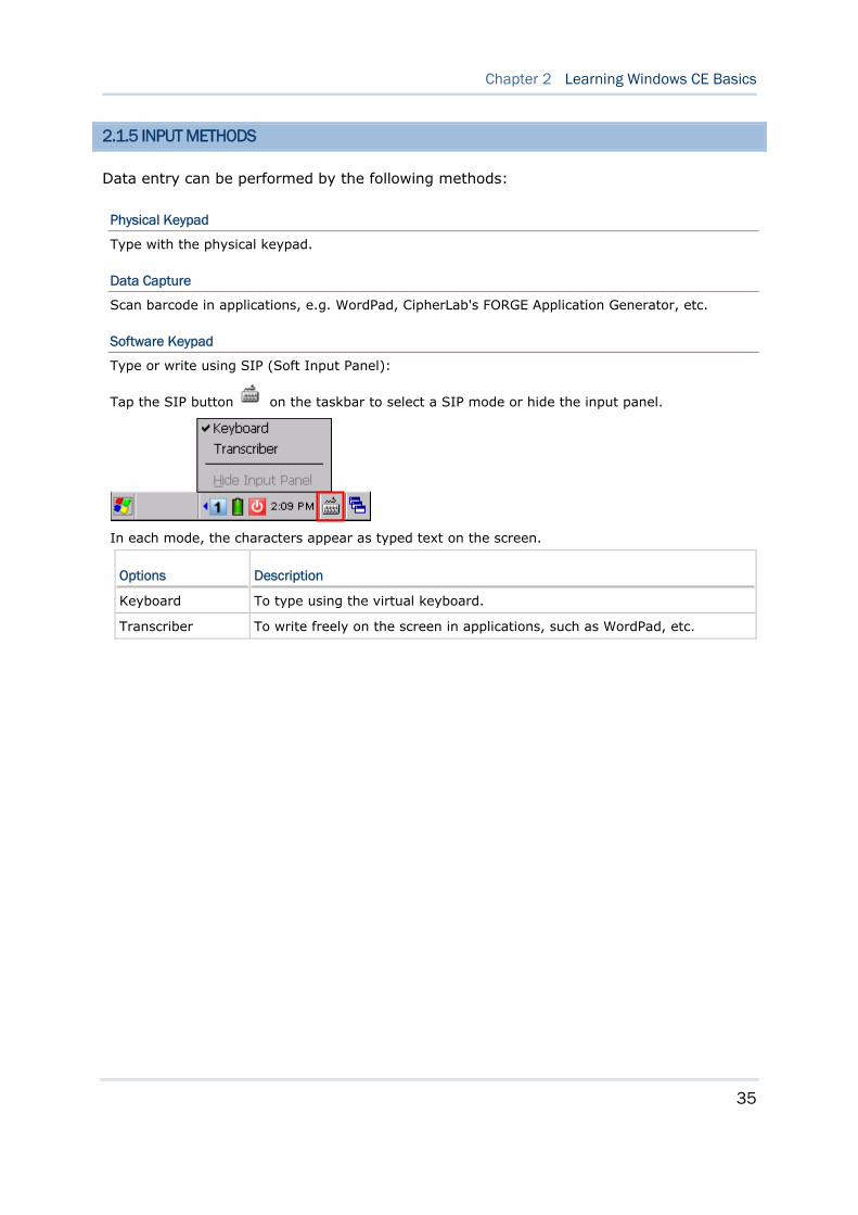
2.1.5 INPUT METHODS
Data entry can be performed by the following methods:
Physical Keypad
Type with the physical keypad.
Data Capture
Scan barcode in applications, e.g. WordPad, CipherLab's FORGE Application Generator, etc.
Software Keypad
Type or write using SIP (Soft Input Panel):
Tap the SIP button on the taskbar to select a SIP mode or hide the input panel.
In each mode, the characters appear as typed text on the screen.
Options Description
Keyboard To type using the virtual keyboard.
Transcriber To write freely on the screen in applications, such as WordPad, etc.
36
9300 Mobile Computer Reference Manual
2.2 MANAGING PROGRAMS
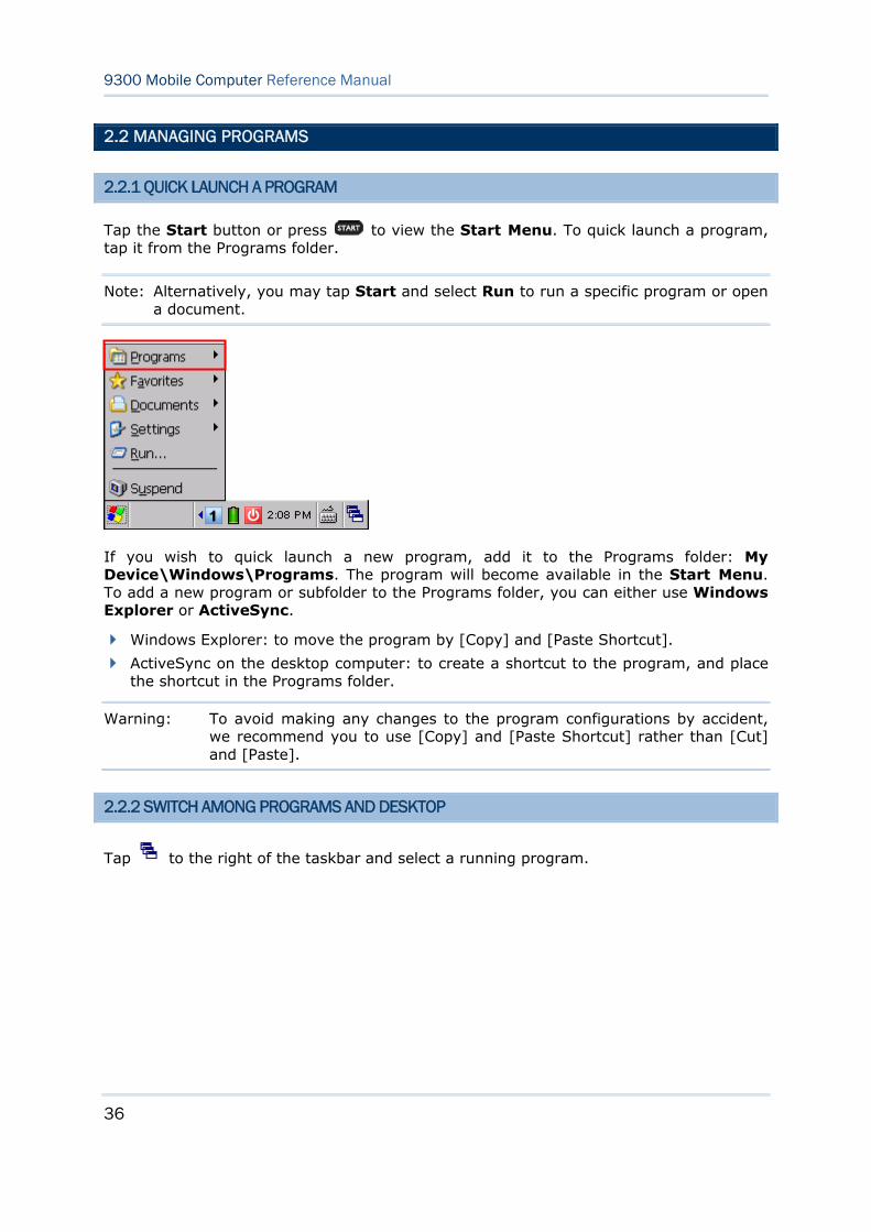
2.2.1 QUICK LAUNCH A PROGRAM
Tap the Start button or press to view the Start Menu. To quick launch a program, tap it from the Programs folder.
Note: Alternatively, you may tap Start and select Run to run a specific program or open a document.
If you wish to quick launch a new program, add it to the Programs folder: My Device\Windows\Programs. The program will become available in the Start Menu. To add a new program or subfolder to the Programs folder, you can either use Windows Explorer or ActiveSync.
Windows Explorer: to move the program by [Copy] and [Paste Shortcut].
ActiveSync on the desktop computer: to create a shortcut to the program, and place the shortcut in the Programs folder.
Warning: To avoid making any changes to the program configurations by accident, we recommend you to use [Copy] and [Paste Shortcut] rather than [Cut] and [Paste].
2.2.2 SWITCH AMONG PROGRAMS AND DESKTOP
Tap to the right of the taskbar and select a running program.
37
Chapter 2 Learning Windows CE Basics
2.2.3 EXIT A PROGRAM
In general, the system manages memory automatically, and there is no need to exit a program in order to open another or to conserve memory. However, random access memory (SDRAM) may be used up when running too many programs. As a result, it will slow down the operation or cause program errors. In that case, you should stop one or more running programs to free memory. In order to use memory in a more efficient way, you are recommended to exit a program when it is not desired any longer.
Warning: Always remember to save data or settings before you exit a program.
Tap to close an active window, a dialog box, or a running application. If the button is not displayed on the toolbar, press [ESC] on the physical keypad.
Tap to save the current settings and exit the application (or minimize the window in some applications). If the button is not displayed on the toolbar, press [Enter] on the physical keypad.
Note: Some programs, such as the Reader Configuration Utility (ReaderConfig.exe), may create an associated icon on the taskbar. You may tap the icon and select [Exit] from the pop-up menu.
38
9300 Mobile Computer Reference Manual
2.3 USING ACTIVESYNC
ActiveSync is used to synchronize information between 9300 Mobile Computer and your desktop computer, to install programs on the mobile computer, and to backup and restore the mobile computer.
The Microsoft ActiveSync program has to be installed on your desktop computer first.
To download the up-to-date version of the program, you may need to go to Microsoft's official web site for Windows Mobile devices as shown below.
http://www.microsoft.com/windowsmobile/activesync/activesync45.mspx
After downloading and installation, run the program. For detailed information on the program, you may click the Help menu, and then select the Microsoft ActiveSync Help.
2.3.1 SYNCHRONIZATION WITH YOUR COMPUTER
1) Follow these instructions for initial ActiveSync operation:
Connect the USB charging & communication cable from the mobile computer or via a cradle to your computer.
Connect the power cable to a nearby power outlet.
Turn on the mobile computer or seat it in the cradle.
2) Your computer will automatically detect the USB device.
3) Select which partnership to set up. If you want to synchronize data between the mobile computer and your personal computer, select Standard Partnership; otherwise, select Guest Partnership.
4) Wait a few seconds for the mobile computer to get connected (and synchronized if a Standard Partnership is selected).
Note: For ActiveSync via Bluetooth, refer to Using Bluetooth.
39
Chapter 2 Learning Windows CE Basics
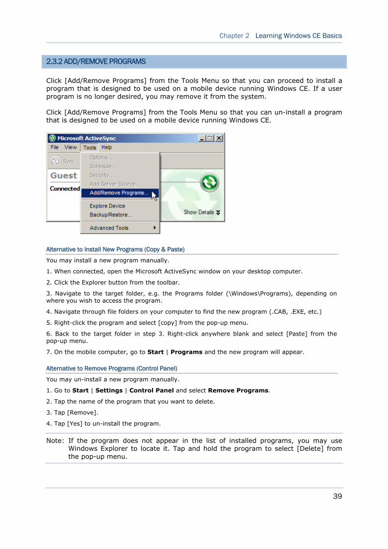
2.3.2 ADD/REMOVE PROGRAMS
Click [Add/Remove Programs] from the Tools Menu so that you can proceed to install a program that is designed to be used on a mobile device running Windows CE. If a user program is no longer desired, you may remove it from the system.
Click [Add/Remove Programs] from the Tools Menu so that you can un-install a program that is designed to be used on a mobile device running Windows CE.
Alternative to Install New Programs (Copy & Paste)
You may install a new program manually.
1. When connected, open the Microsoft ActiveSync window on your desktop computer.
2. Click the Explorer button from the toolbar.
3. Navigate to the target folder, e.g. the Programs folder (\Windows\Programs), depending on where you wish to access the program.
4. Navigate through file folders on your computer to find the new program (.CAB, .EXE, etc.)
5. Right-click the program and select [copy] from the pop-up menu.
6. Back to the target folder in step 3. Right-click anywhere blank and select [Paste] from the pop-up menu.
7. On the mobile computer, go to Start | Programs and the new program will appear.
Alternative to Remove Programs (Control Panel)
You may un-install a new program manually.
1. Go to Start | Settings | Control Panel and select Remove Programs.
2. Tap the name of the program that you want to delete.
3. Tap [Remove].
4. Tap [Yes] to un-install the program.
Note: If the program does not appear in the list of installed programs, you may use Windows Explorer to locate it. Tap and hold the program to select [Delete] from the pop-up menu.
40
9300 Mobile Computer Reference Manual
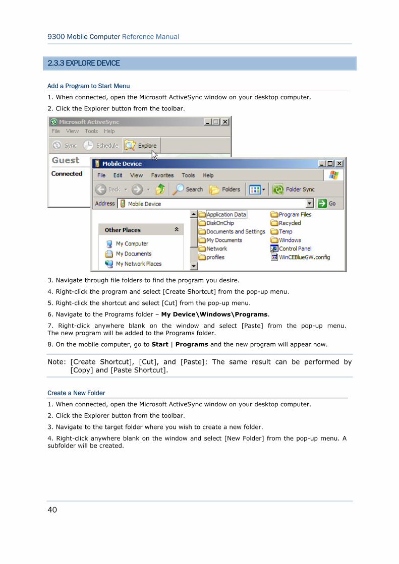
2.3.3 EXPLORE DEVICE
Add a Program to Start Menu
1. When connected, open the Microsoft ActiveSync window on your desktop computer.
2. Click the Explorer button from the toolbar.
3. Navigate through file folders to find the program you desire.
4. Right-click the program and select [Create Shortcut] from the pop-up menu.
5. Right-click the shortcut and select [Cut] from the pop-up menu.
6. Navigate to the Programs folder – My Device\Windows\Programs.
7. Right-click anywhere blank on the window and select [Paste] from the pop-up menu. The new program will be added to the Programs folder.
8. On the mobile computer, go to Start | Programs and the new program will appear now.
Note: [Create Shortcut], [Cut], and [Paste]: The same result can be performed by [Copy] and [Paste Shortcut].
Create a New Folder
1. When connected, open the Microsoft ActiveSync window on your desktop computer.
2. Click the Explorer button from the toolbar.
3. Navigate to the target folder where you wish to create a new folder.
4. Right-click anywhere blank on the window and select [New Folder] from the pop-up menu. A subfolder will be created.
41
Chapter 2 Learning Windows CE Basics
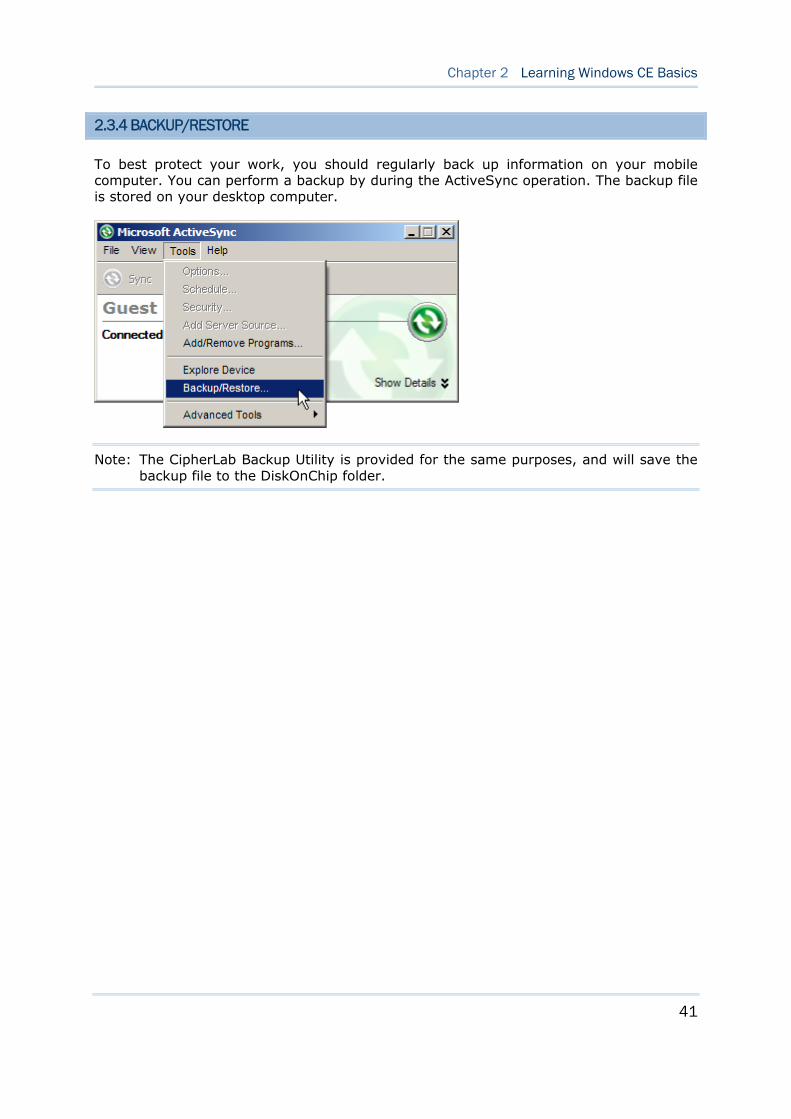
2.3.4 BACKUP/RESTORE
To best protect your work, you should regularly back up information on your mobile computer. You can perform a backup by during the ActiveSync operation. The backup file is stored on your desktop computer.
Note: The CipherLab Backup Utility is provided for the same purposes, and will save the backup file to the DiskOnChip folder.
42
9300 Mobile Computer Reference Manual
2.4 USING WINDOWS EXPLORER
2.4.1 ADD A PROGRAM TO START MENU
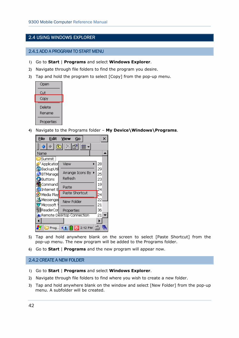
1) Go to Start | Programs and select Windows Explorer.
2) Navigate through file folders to find the program you desire.
3) Tap and hold the program to select [Copy] from the pop-up menu.
4) Navigate to the Programs folder – My Device\Windows\Programs.
5) Tap and hold anywhere blank on the screen to select [Paste Shortcut] from the pop-up menu. The new program will be added to the Programs folder.
6) Go to Start | Programs and the new program will appear now.
2.4.2 CREATE A NEW FOLDER
1) Go to Start | Programs and select Windows Explorer.
2) Navigate through file folders to find where you wish to create a new folder.
3) Tap and hold anywhere blank on the window and select [New Folder] from the pop-up menu. A subfolder will be created.
43
Chapter 2 Learning Windows CE Basics
2.5 SYSTEM RESET
Reset the mobile computer when it stops responding to input.
Software Reset: Press the [RESET] button.
Hardware Reset: Press the [RESET] button and at the same time for about 2 seconds.
Warning: Never perform hardware reset unless software reset cannot solve your problems.
2.5.1 SOFTWARE RESET (WARM REBOOT)
Software reset, also known as a warm boot, will restart the mobile computer and keep all the saved files. To perform software reset, use the stylus to press the [RESET] button.
During operation, the removal of main battery will start software reset too.
Warning: Data loss may occur when files are not properly closed before software reset.
2.5.2 HARDWARE RESET (COLD REBOOT)
Hardware reset, also known as a cold boot, will restart the mobile computer and initializes SDRAM. Data and program files stored in SDRAM will be erased after hardware reset. But you can restore data that is previously synchronized with your computer by performing an ActiveSync operation, or backed up by using CipherLab Backup Utility.
Warning: Only the files stored in the Flash File System are retained during hardware reset.
44
9300 Mobile Computer Reference Manual
2.5.3 DATE/TIME & TIME ZONE AFTER RESET
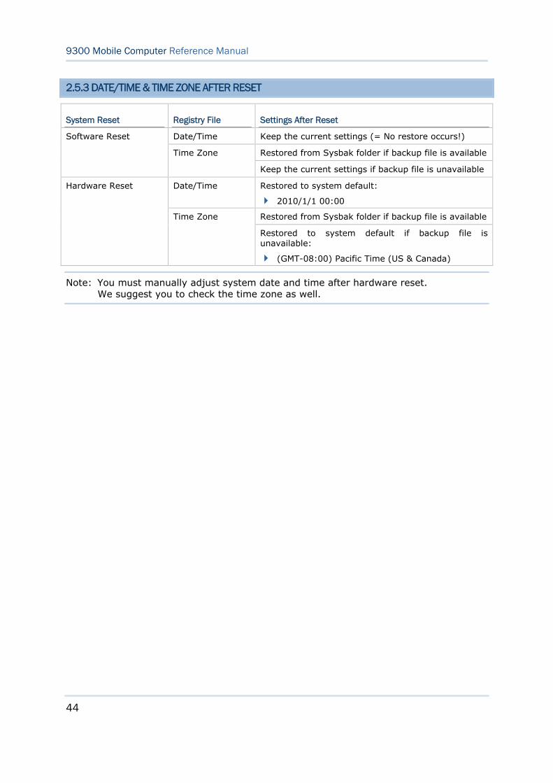
System Reset Registry File Settings After Reset
Date/Time Keep the current settings (= No restore occurs!)
Restored from Sysbak folder if backup file is available
Software Reset
Time Zone
Keep the current settings if backup file is unavailable
Date/Time Restored to system default:
2010/1/1 00:00
Restored from Sysbak folder if backup file is available
Hardware Reset
Time Zone
Restored to system default if backup file is unavailable:
(GMT-08:00) Pacific Time (US & Canada)
Note: You must manually adjust system date and time after hardware reset. We suggest you to check the time zone as well.
45
Chapter 2 Learning Windows CE Basics
2.6 AUTO RUN
Upon hardware or software reset, the OS shall automatically execute AutoRun.exe and/or AutoRun.ini if any of the two files can be found in the “\DiskOnChip” folder.
If AutoRun.exe exists
Upon cold boot, the OS shall automatically execute AutoRun.exe
Upon warm boot, the OS shall automatically execute AutoRun.exe
If AutoRun.ini exists
Upon cold boot, the OS shall automatically check the contents of AutoRun.ini and execute them (if there is any).
Any line prefixed with a semicolon “;” is supposed to be a comment line only; otherwise it is an executable file or command and shall be executed (line by line). For example,
\DiskOnChip\cerdisp.exe
:\DiskOnChip\ReaderConfig.exe
;\DiskOnChip\RF9300_CE.exe
\DiskOnChip\cerdisp.cab
:\DiskOnChip\ReaderConfig.cab
Upon warm boot, the OS shall automatically check the contents of AutoRun.ini and execute any line that is prefixed with a colon “:”.
Any line prefixed with a semicolon “;” is supposed to be a comment line only. For example,
:\DiskOnChip\ReaderConfig.exe
;\DiskOnChip\RF9300_CE.exe
:\DiskOnChip\ReaderConfig.cab
Note: Because the cabinet files are designed to install the application, tidy up, and then “self destruct”, they will be automatically deleted from your mobile computer after installation. However, AutoRun.ini will backup the original files (.cab) while installing cabinet files, and restore them after installation. Consequently, these cabinet files will be automatically re-installed to your mobile computer upon cold boot or warm boot, if specified in AutoRun.ini.

46
9300 Mobile Computer Reference Manual
47
In this chapter, a brief on the system settings is provided for your reference. The Application Manager is specifically designed for the administrator to manage the accessibility of applications and protect the integrity of the system on the mobile computer. It serves as a portal that allows launching routine application programs automatically upon a reboot, preventing users from running potentially distracting applications, as well as to restricting access to changing device settings.
Note: User settings are stored in SDRAM and will be overwritten by the system defaults after hardware reset. However, you can use the CipherLab Backup Utility to backup the current registry for restore purpose.
IN THIS CHAPTER
3.1 Application Manager ................................................... 47 3.2 Device Name & Configuration ...................................... 48 3.3 System Settings ........................................................ 50 3.4 Connection Settings ................................................... 53 3.5 Upgrading OS Image.................................................. 55
3.1 APPLICATION MANAGER
Application Manager has powerful features and is easy to use —
Provides full control over executable files of the Programs folder, desktop and Control (Panel)
Can limit access to essential device settings
Can prevent from potentially distracting applications
Can execute routine application automatically upon a reboot
Provides user name and/or password protection
Allows setting up an administrator account
Supports multiple languages
Supports show/hide taskbar and toolbar
Supports enable/disable taskbar, partially or fully
Distributes user settings at a few clicks
After restarting the mobile computer upon completion of installation, the Application Manager automatically starts up with programs and settings made accessible based on the system. If you have logged in as an administrator, you are allowed to manage program accessibility.
Note: For details on the installation and usage, please refer to the separate user guide.
Chapter 3 CONFIGURING 9300 MOBILE COMPUTER
48
9300 Mobile Computer Reference Manual
3.2 DEVICE NAME & CONFIGURATION
3.2.1 CHANGING DEVICE NAME
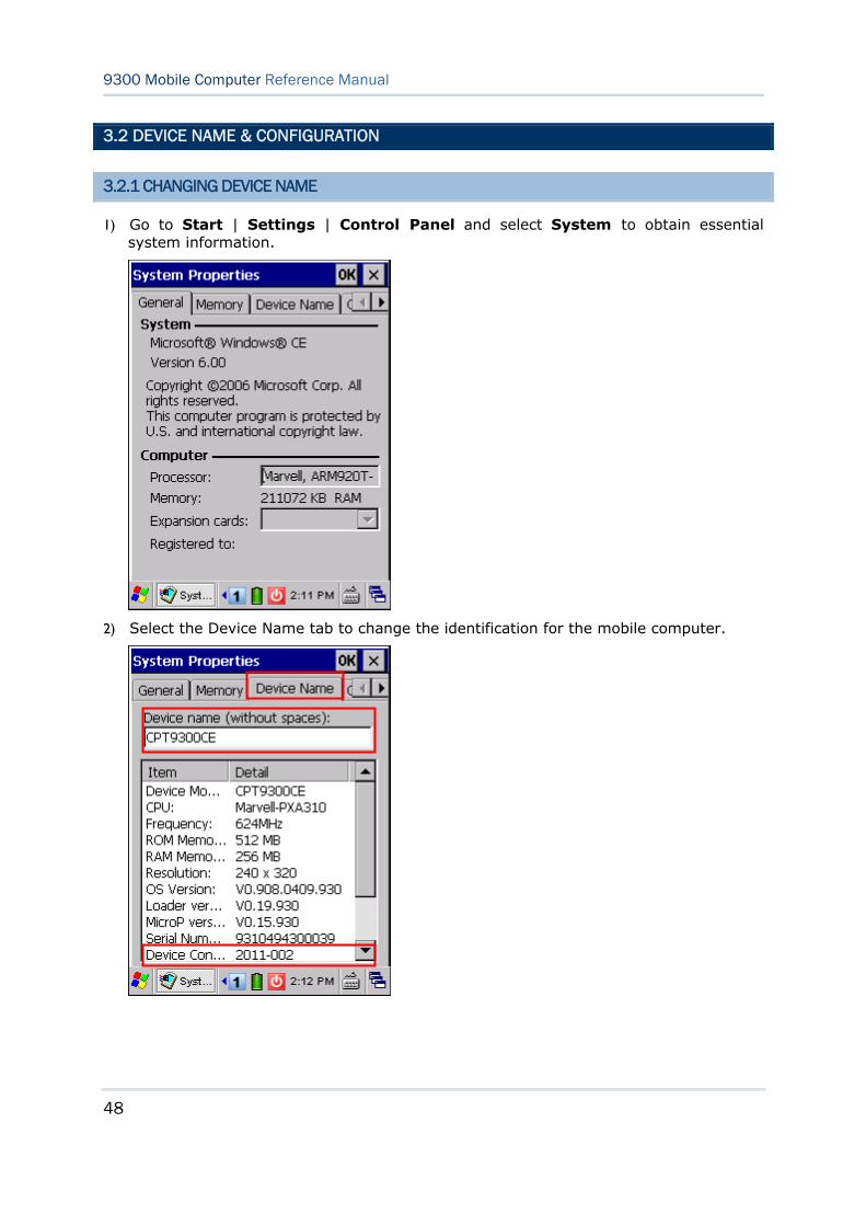
1) Go to Start | Settings | Control Panel and select System to obtain essential system information.
2) Select the Device Name tab to change the identification for the mobile computer.
49
Chapter 3 Configuring 9300 Mobile Computer
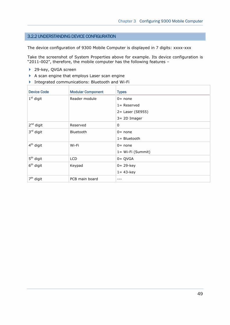
3.2.2 UNDERSTANDING DEVICE CONFIGURATION
The device configuration of 9300 Mobile Computer is displayed in 7 digits: xxxx-xxx
Take the screenshot of System Properties above for example. Its device configuration is “2011-002”, therefore, the mobile computer has the following features –
29-key, QVGA screen
A scan engine that employs Laser scan engine
Integrated communications: Bluetooth and Wi-Fi
Device Code Modular Component Types
1st digit Reader module 0= none
1= Reserved
2= Laser (SE955)
3= 2D Imager
2nd digit Reserved 0
3rd digit Bluetooth 0= none
1= Bluetooth
4th digit Wi-Fi 0= none
1= Wi-Fi (Summit)
5th digit LCD 0= QVGA
6th digit Keypad 0= 29-key
1= 43-key
7th digit PCB main board ---
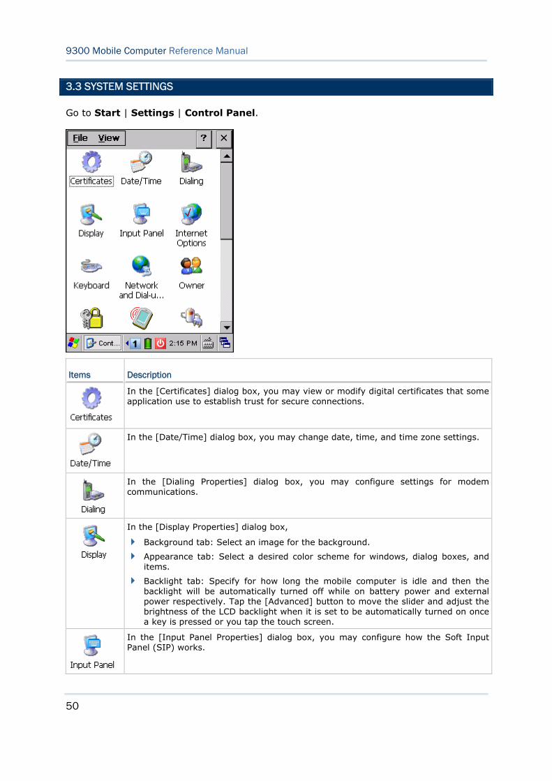
50
9300 Mobile Computer Reference Manual
3.3 SYSTEM SETTINGS
Go to Start | Settings | Control Panel.
Items Description
In the [Certificates] dialog box, you may view or modify digital certificates that some application use to establish trust for secure connections.
In the [Date/Time] dialog box, you may change date, time, and time zone settings.
In the [Dialing Properties] dialog box, you may configure settings for modem communications.
In the [Display Properties] dialog box,
Background tab: Select an image for the background.
Appearance tab: Select a desired color scheme for windows, dialog boxes, and items.
Backlight tab: Specify for how long the mobile computer is idle and then the backlight will be automatically turned off while on battery power and external power respectively. Tap the [Advanced] button to move the slider and adjust the brightness of the LCD backlight when it is set to be automatically turned on once a key is pressed or you tap the touch screen.
In the [Input Panel Properties] dialog box, you may configure how the Soft Input Panel (SIP) works.
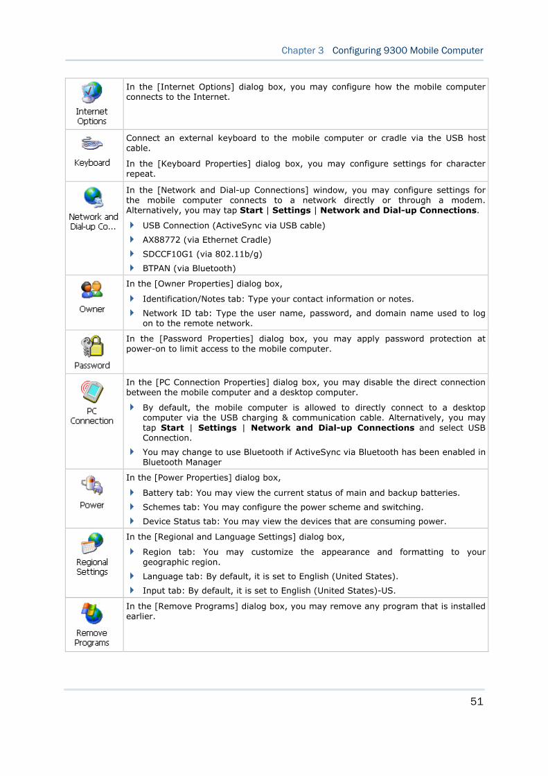
51
Chapter 3 Configuring 9300 Mobile Computer
In the [Internet Options] dialog box, you may configure how the mobile computer connects to the Internet.
Connect an external keyboard to the mobile computer or cradle via the USB host cable.
In the [Keyboard Properties] dialog box, you may configure settings for character repeat.
In the [Network and Dial-up Connections] window, you may configure settings for the mobile computer connects to a network directly or through a modem. Alternatively, you may tap Start | Settings | Network and Dial-up Connections.
USB Connection (ActiveSync via USB cable)
AX88772 (via Ethernet Cradle)
SDCCF10G1 (via 802.11b/g)
BTPAN (via Bluetooth)
In the [Owner Properties] dialog box,
Identification/Notes tab: Type your contact information or notes.
Network ID tab: Type the user name, password, and domain name used to log on to the remote network.
In the [Password Properties] dialog box, you may apply password protection at power-on to limit access to the mobile computer.
In the [PC Connection Properties] dialog box, you may disable the direct connection between the mobile computer and a desktop computer.
By default, the mobile computer is allowed to directly connect to a desktop computer via the USB charging & communication cable. Alternatively, you may tap Start | Settings | Network and Dial-up Connections and select USB Connection.
You may change to use Bluetooth if ActiveSync via Bluetooth has been enabled in Bluetooth Manager
In the [Power Properties] dialog box,
Battery tab: You may view the current status of main and backup batteries.
Schemes tab: You may configure the power scheme and switching.
Device Status tab: You may view the devices that are consuming power.
In the [Regional and Language Settings] dialog box,
Region tab: You may customize the appearance and formatting to your geographic region.
Language tab: By default, it is set to English (United States).
Input tab: By default, it is set to English (United States)-US.
In the [Remove Programs] dialog box, you may remove any program that is installed earlier.
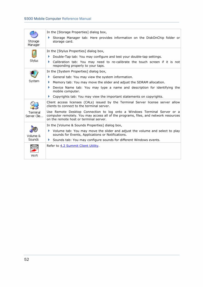
52
9300 Mobile Computer Reference Manual
In the [Storage Properties] dialog box,
Storage Manager tab: Here provides information on the DiskOnChip folder or storage card.
In the [Stylus Properties] dialog box,
Double-Tap tab: You may configure and test your double-tap settings.
Calibration tab: You may need to re-calibrate the touch screen if it is not responding properly to your taps.
In the [System Properties] dialog box,
General tab: You may view the system information.
Memory tab: You may move the slider and adjust the SDRAM allocation.
Device Name tab: You may type a name and description for identifying the mobile computer.
Copyrights tab: You may view the important statements on copyrights.
Client access licenses (CALs) issued by the Terminal Server license server allow clients to connect to the terminal server.
Use Remote Desktop Connection to log onto a Windows Terminal Server or a computer remotely. You may access all of the programs, files, and network resources on the remote host or terminal server.
In the [Volume & Sounds Properties] dialog box,
Volume tab: You may move the slider and adjust the volume and select to play sounds for Events, Applications or Notifications.
Sounds tab: You may configure sounds for different Windows events.
Refer to 4.2 Summit Client Utility.
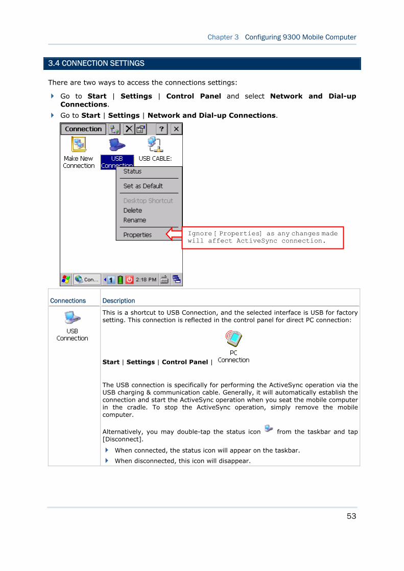
53
Chapter 3 Configuring 9300 Mobile Computer
3.4 CONNECTION SETTINGS
There are two ways to access the connections settings:
Go to Start | Settings | Control Panel and select Network and Dial-up Connections.
Go to Start | Settings | Network and Dial-up Connections.
Connections Description
This is a shortcut to USB Connection, and the selected interface is USB for factory setting. This connection is reflected in the control panel for direct PC connection:
Start | Settings | Control Panel |
The USB connection is specifically for performing the ActiveSync operation via the USB charging & communication cable. Generally, it will automatically establish the connection and start the ActiveSync operation when you seat the mobile computer in the cradle. To stop the ActiveSync operation, simply remove the mobile computer.
Alternatively, you may double-tap the status icon from the taskbar and tap [Disconnect].
When connected, the status icon will appear on the taskbar.
When disconnected, this icon will disappear.
Ignore [Properties] as any changes made will affect ActiveSync connection.
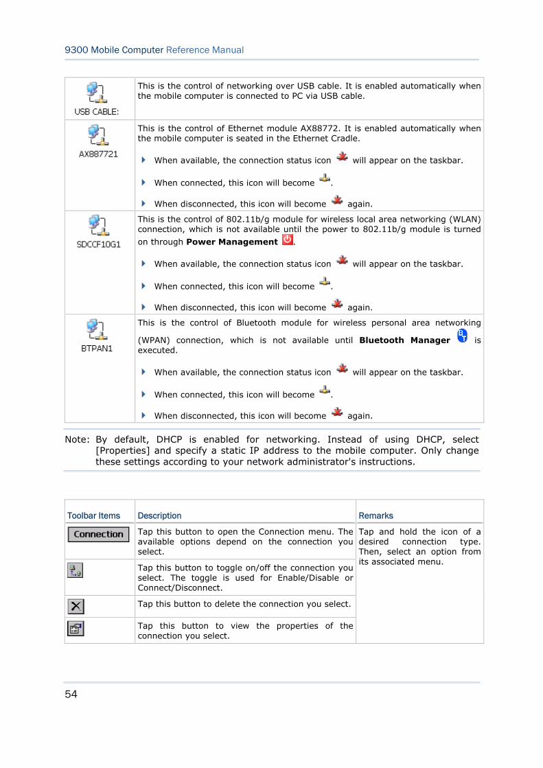
54
9300 Mobile Computer Reference Manual
This is the control of networking over USB cable. It is enabled automatically when the mobile computer is connected to PC via USB cable.
This is the control of Ethernet module AX88772. It is enabled automatically when the mobile computer is seated in the Ethernet Cradle.
When available, the connection status icon will appear on the taskbar.
When connected, this icon will become .
When disconnected, this icon will become again.
This is the control of 802.11b/g module for wireless local area networking (WLAN) connection, which is not available until the power to 802.11b/g module is turned
on through Power Management .
When available, the connection status icon will appear on the taskbar.
When connected, this icon will become .
When disconnected, this icon will become again.
This is the control of Bluetooth module for wireless personal area networking
(WPAN) connection, which is not available until Bluetooth Manager is executed.
When available, the connection status icon will appear on the taskbar.
When connected, this icon will become .
When disconnected, this icon will become again.
Note: By default, DHCP is enabled for networking. Instead of using DHCP, select [Properties] and specify a static IP address to the mobile computer. Only change these settings according to your network administrator's instructions.
Toolbar Items Description Remarks
Tap this button to open the Connection menu. The available options depend on the connection you select.
Tap this button to toggle on/off the connection you select. The toggle is used for Enable/Disable or Connect/Disconnect.
Tap this button to delete the connection you select.
Tap this button to view the properties of the connection you select.
Tap and hold the icon of a desired connection type. Then, select an option from its associated menu.
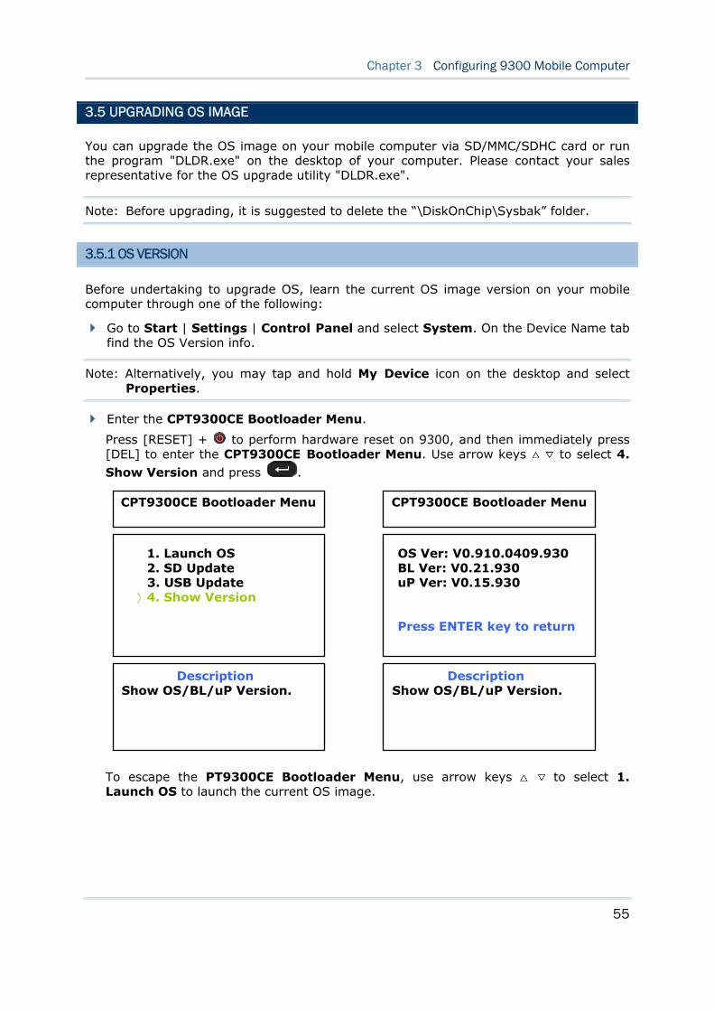
55
Chapter 3 Configuring 9300 Mobile Computer
3.5 UPGRADING OS IMAGE
You can upgrade the OS image on your mobile computer via SD/MMC/SDHC card or run the program "DLDR.exe" on the desktop of your computer. Please contact your sales representative for the OS upgrade utility "DLDR.exe".
Note: Before upgrading, it is suggested to delete the “\DiskOnChip\Sysbak” folder.
3.5.1 OS VERSION
Before undertaking to upgrade OS, learn the current OS image version on your mobile computer through one of the following:
Go to Start | Settings | Control Panel and select System. On the Device Name tab find the OS Version info.
Note: Alternatively, you may tap and hold My Device icon on the desktop and select Properties.
Enter the CPT9300CE Bootloader Menu.
Press [RESET] + to perform hardware reset on 9300, and then immediately press [DEL] to enter the CPT9300CE Bootloader Menu. Use arrow keys to select 4.
Show Version and press .
To escape the PT9300CE Bootloader Menu, use arrow keys to select 1. Launch OS to launch the current OS image.
Description Show OS/BL/uP Version.
1. Launch OS 2. SD Update 3. USB Update
〉4. Show Version
Description Show OS/BL/uP Version.
OS Ver: V0.910.0409.930 BL Ver: V0.21.930 uP Ver: V0.15.930 Press ENTER key to return
CPT9300CE Bootloader Menu CPT9300CE Bootloader Menu
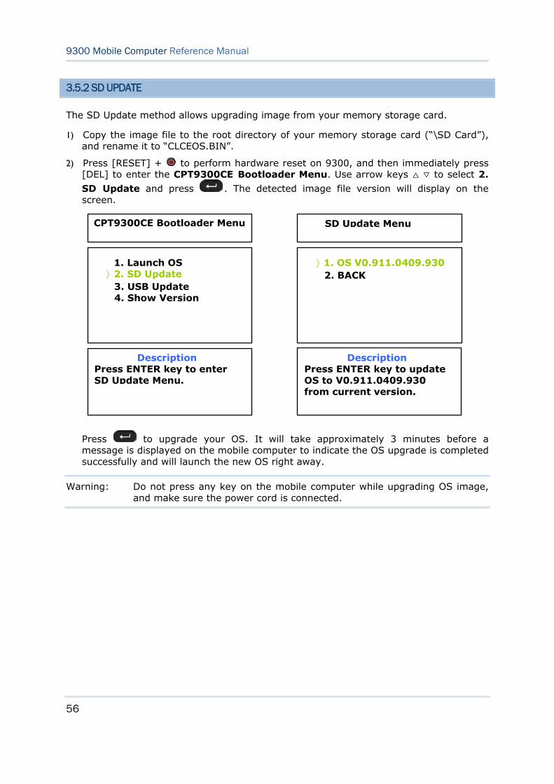
56
9300 Mobile Computer Reference Manual
3.5.2 SD UPDATE
The SD Update method allows upgrading image from your memory storage card.
1) Copy the image file to the root directory of your memory storage card (“\SD Card”), and rename it to “CLCEOS.BIN”.
2) Press [RESET] + to perform hardware reset on 9300, and then immediately press [DEL] to enter the CPT9300CE Bootloader Menu. Use arrow keys to select 2.
SD Update and press . The detected image file version will display on the screen.
Press to upgrade your OS. It will take approximately 3 minutes before a message is displayed on the mobile computer to indicate the OS upgrade is completed successfully and will launch the new OS right away.
Warning: Do not press any key on the mobile computer while upgrading OS image, and make sure the power cord is connected.
Description Press ENTER key to enter SD Update Menu.
1. Launch OS 〉2. SD Update
3. USB Update 4. Show Version
SD Update Menu
Description Press ENTER key to update OS to V0.911.0409.930 from current version.
〉1. OS V0.911.0409.930 2. BACK
CPT9300CE Bootloader Menu
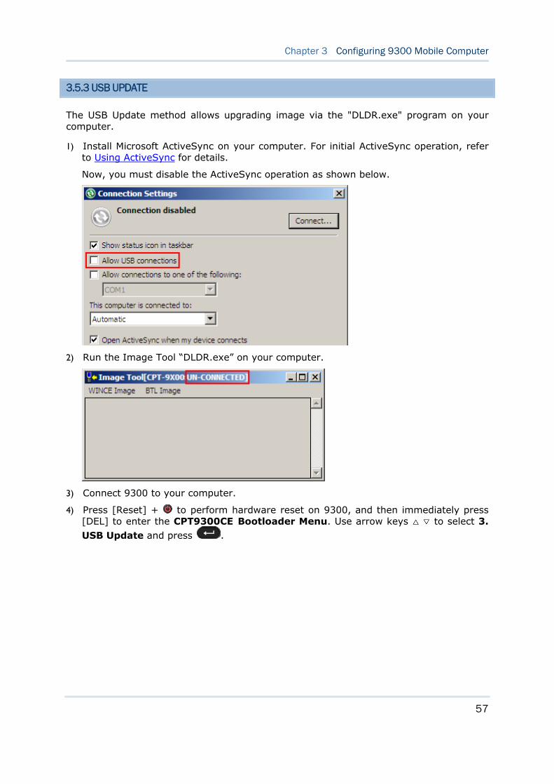
57
Chapter 3 Configuring 9300 Mobile Computer
3.5.3 USB UPDATE
The USB Update method allows upgrading image via the "DLDR.exe" program on your computer.
1) Install Microsoft ActiveSync on your computer. For initial ActiveSync operation, refer to Using ActiveSync for details.
Now, you must disable the ActiveSync operation as shown below.
2) Run the Image Tool “DLDR.exe” on your computer.
3) Connect 9300 to your computer.
4) Press [Reset] + to perform hardware reset on 9300, and then immediately press [DEL] to enter the CPT9300CE Bootloader Menu. Use arrow keys to select 3.
USB Update and press .
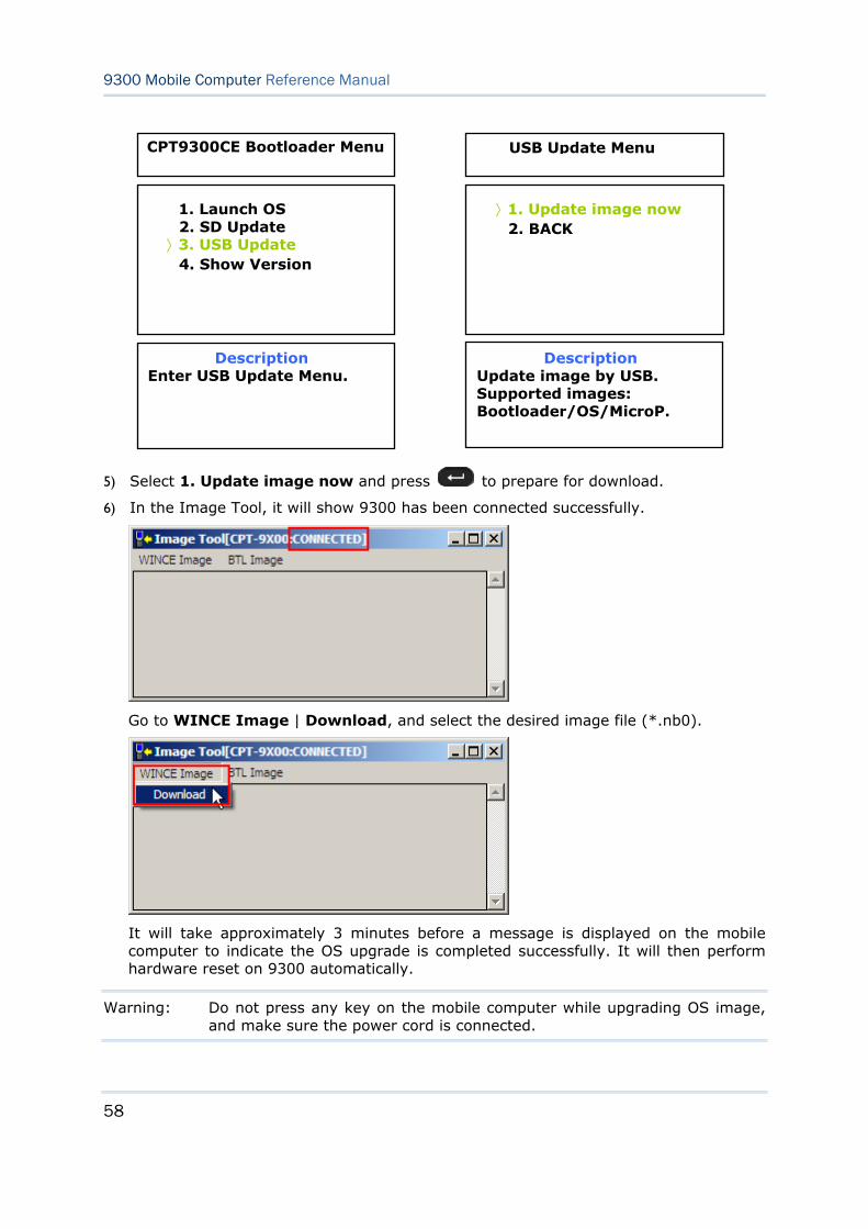
58
9300 Mobile Computer Reference Manual
5) Select 1. Update image now and press to prepare for download.
6) In the Image Tool, it will show 9300 has been connected successfully.
Go to WINCE Image | Download, and select the desired image file (*.nb0).
It will take approximately 3 minutes before a message is displayed on the mobile computer to indicate the OS upgrade is completed successfully. It will then perform hardware reset on 9300 automatically.
Warning: Do not press any key on the mobile computer while upgrading OS image, and make sure the power cord is connected.
Description Enter USB Update Menu.
1. Launch OS 2. SD Update
〉3. USB Update 4. Show Version
USB Update Menu
Description Update image by USB. Supported images: Bootloader/OS/MicroP.
〉1. Update image now 2. BACK
CPT9300CE Bootloader Menu
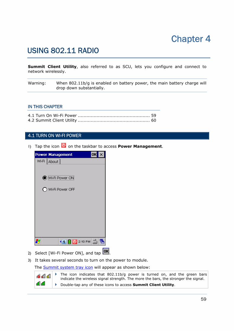
59
Summit Client Utility, also referred to as SCU, lets you configure and connect to network wirelessly.
Warning: When 802.11b/g is enabled on battery power, the main battery charge will drop down substantially.
IN THIS CHAPTER
4.1 Turn On Wi-Fi Power .................................................. 59 4.2 Summit Client Utility .................................................. 60
4.1 TURN ON WI-FI POWER
1) Tap the icon on the taskbar to access Power Management.
2) Select [Wi-Fi Power ON], and tap .
3) It takes several seconds to turn on the power to module.
The Summit system tray icon will appear as shown below:
The icon indicates that 802.11b/g power is turned on, and the green bars indicate the wireless signal strength. The more the bars, the stronger the signal.
Double-tap any of these icons to access Summit Client Utility.
Chapter 4 USING 802.11 RADIO
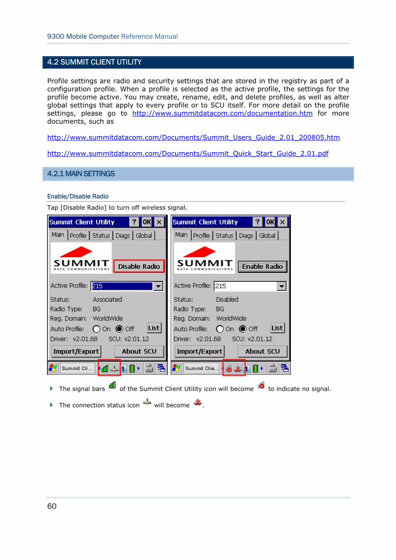
60
9300 Mobile Computer Reference Manual
4.2 SUMMIT CLIENT UTILITY
Profile settings are radio and security settings that are stored in the registry as part of a configuration profile. When a profile is selected as the active profile, the settings for the profile become active. You may create, rename, edit, and delete profiles, as well as alter global settings that apply to every profile or to SCU itself. For more detail on the profile settings, please go to http://www.summitdatacom.com/documentation.htm for more documents, such as
http://www.summitdatacom.com/Documents/Summit_Users_Guide_2.01_200805.htm
http://www.summitdatacom.com/Documents/Summit_Quick_Start_Guide_2.01.pdf
4.2.1 MAIN SETTINGS
Enable/Disable Radio
Tap [Disable Radio] to turn off wireless signal.
The signal bars of the Summit Client Utility icon will become to indicate no signal.
The connection status icon will become .
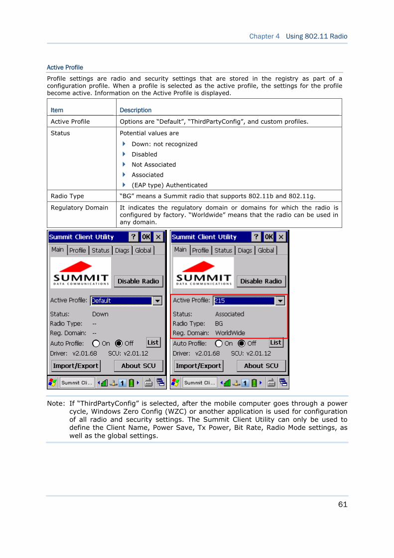
61
Chapter 4 Using 802.11 Radio
Active Profile
Profile settings are radio and security settings that are stored in the registry as part of a configuration profile. When a profile is selected as the active profile, the settings for the profile become active. Information on the Active Profile is displayed.
Item Description
Active Profile Options are “Default”, “ThirdPartyConfig”, and custom profiles.
Status Potential values are
Down: not recognized
Disabled
Not Associated
Associated
(EAP type) Authenticated
Radio Type “BG” means a Summit radio that supports 802.11b and 802.11g.
Regulatory Domain It indicates the regulatory domain or domains for which the radio is configured by factory. “Worldwide” means that the radio can be used in any domain.
Note: If “ThirdPartyConfig” is selected, after the mobile computer goes through a power cycle, Windows Zero Config (WZC) or another application is used for configuration of all radio and security settings. The Summit Client Utility can only be used to define the Client Name, Power Save, Tx Power, Bit Rate, Radio Mode settings, as well as the global settings.
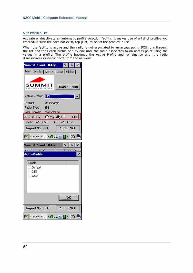
62
9300 Mobile Computer Reference Manual
Auto Profile & List
Activate or deactivate an automatic profile selection facility. It makes use of a list of profiles you created. If such list does not exist, tap [List] to select the profiles in use.
When the facility is active and the radio is not associated to an access point, SCU runs through the list and tries each profile one by one until the radio associates to an access point using the values in a profile. The profile becomes the Active Profile and remains so until the radio disassociates or disconnects from the network.
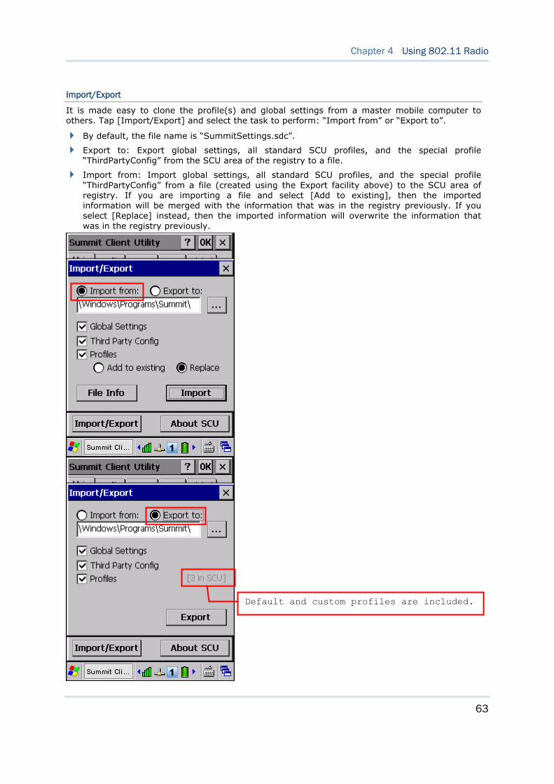
63
Chapter 4 Using 802.11 Radio
Import/Export
It is made easy to clone the profile(s) and global settings from a master mobile computer to others. Tap [Import/Export] and select the task to perform: “Import from” or “Export to”.
By default, the file name is “SummitSettings.sdc”.
Export to: Export global settings, all standard SCU profiles, and the special profile “ThirdPartyConfig” from the SCU area of the registry to a file.
Import from: Import global settings, all standard SCU profiles, and the special profile “ThirdPartyConfig” from a file (created using the Export facility above) to the SCU area of registry. If you are importing a file and select [Add to existing], then the imported information will be merged with the information that was in the registry previously. If you select [Replace] instead, then the imported information will overwrite the information that was in the registry previously.
Default and custom profiles are included.
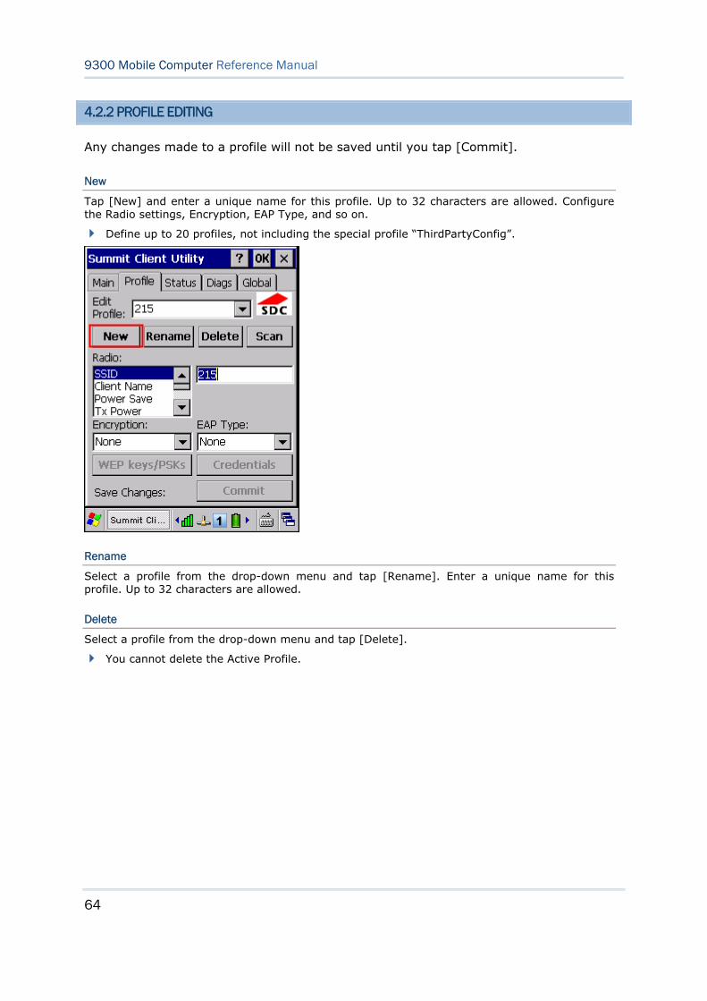
64
9300 Mobile Computer Reference Manual
4.2.2 PROFILE EDITING
Any changes made to a profile will not be saved until you tap [Commit].
New
Tap [New] and enter a unique name for this profile. Up to 32 characters are allowed. Configure the Radio settings, Encryption, EAP Type, and so on.
Define up to 20 profiles, not including the special profile “ThirdPartyConfig”.
Rename
Select a profile from the drop-down menu and tap [Rename]. Enter a unique name for this profile. Up to 32 characters are allowed.
Delete
Select a profile from the drop-down menu and tap [Delete].
You cannot delete the Active Profile.
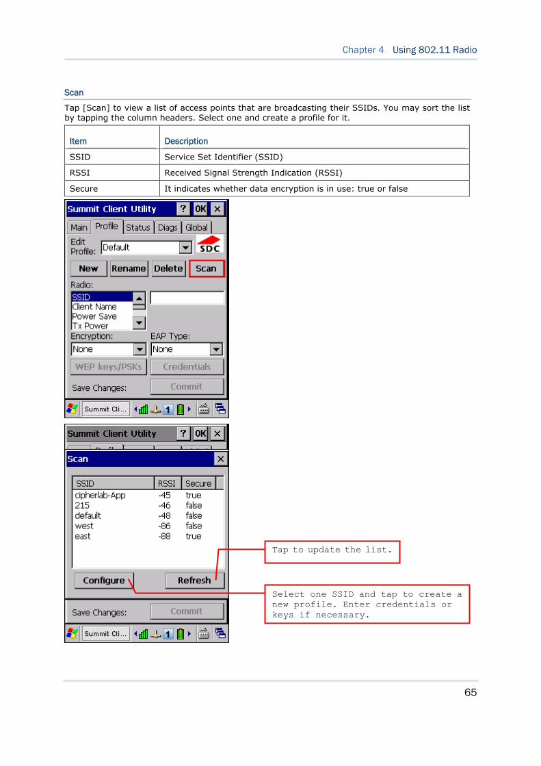
65
Chapter 4 Using 802.11 Radio
Scan
Tap [Scan] to view a list of access points that are broadcasting their SSIDs. You may sort the list by tapping the column headers. Select one and create a profile for it.
Item Description
SSID Service Set Identifier (SSID)
RSSI Received Signal Strength Indication (RSSI)
Secure It indicates whether data encryption is in use: true or false
Tap to update the list.
Select one SSID and tap to create a new profile. Enter credentials or keys if necessary.
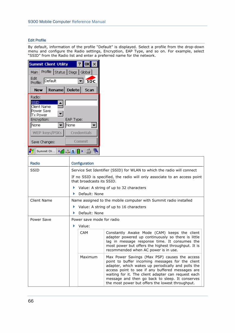
66
9300 Mobile Computer Reference Manual
Edit Profile
By default, information of the profile “Default” is displayed. Select a profile from the drop-down menu and configure the Radio settings, Encryption, EAP Type, and so on. For example, select “SSID” from the Radio list and enter a preferred name for the network.
Radio Configuration
SSID Service Set Identifier (SSID) for WLAN to which the radio will connect
If no SSID is specified, the radio will only associate to an access point that broadcasts its SSID.
Value: A string of up to 32 characters
Default: None
Client Name Name assigned to the mobile computer with Summit radio installed
Value: A string of up to 16 characters
Default: None
Power Save Power save mode for radio
Value:
CAM Constantly Awake Mode (CAM) keeps the client adapter powered up continuously so there is little lag in message response time. It consumes the most power but offers the highest throughput. It is recommended when AC power is in use.
Maximum Max Power Savings (Max PSP) causes the access point to buffer incoming messages for the client adapter, which wakes up periodically and polls the access point to see if any buffered messages are waiting for it. The client adapter can request each message and then go back to sleep. It conserves the most power but offers the lowest throughput.
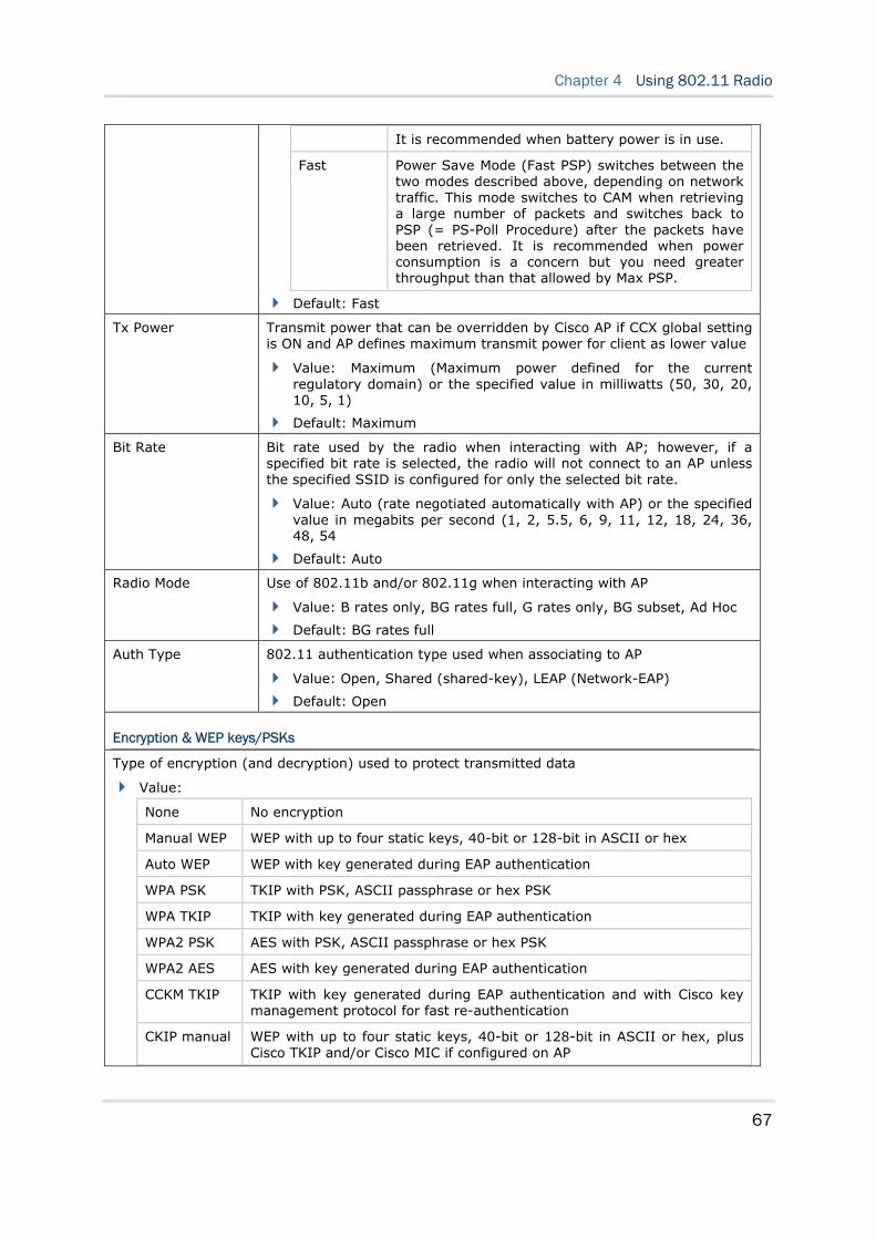
67
Chapter 4 Using 802.11 Radio
It is recommended when battery power is in use.
Fast Power Save Mode (Fast PSP) switches between the two modes described above, depending on network traffic. This mode switches to CAM when retrieving a large number of packets and switches back to PSP (= PS-Poll Procedure) after the packets have been retrieved. It is recommended when power consumption is a concern but you need greater throughput than that allowed by Max PSP.
Default: Fast
Tx Power Transmit power that can be overridden by Cisco AP if CCX global setting is ON and AP defines maximum transmit power for client as lower value
Value: Maximum (Maximum power defined for the current regulatory domain) or the specified value in milliwatts (50, 30, 20, 10, 5, 1)
Default: Maximum
Bit Rate Bit rate used by the radio when interacting with AP; however, if a specified bit rate is selected, the radio will not connect to an AP unless the specified SSID is configured for only the selected bit rate.
Value: Auto (rate negotiated automatically with AP) or the specified value in megabits per second (1, 2, 5.5, 6, 9, 11, 12, 18, 24, 36, 48, 54
Default: Auto
Radio Mode Use of 802.11b and/or 802.11g when interacting with AP
Value: B rates only, BG rates full, G rates only, BG subset, Ad Hoc
Default: BG rates full
Auth Type 802.11 authentication type used when associating to AP
Value: Open, Shared (shared-key), LEAP (Network-EAP)
Default: Open
Encryption & WEP keys/PSKs
Type of encryption (and decryption) used to protect transmitted data
Value:
None No encryption
Manual WEP WEP with up to four static keys, 40-bit or 128-bit in ASCII or hex
Auto WEP WEP with key generated during EAP authentication
WPA PSK TKIP with PSK, ASCII passphrase or hex PSK
WPA TKIP TKIP with key generated during EAP authentication
WPA2 PSK AES with PSK, ASCII passphrase or hex PSK
WPA2 AES AES with key generated during EAP authentication
CCKM TKIP TKIP with key generated during EAP authentication and with Cisco key management protocol for fast re-authentication
CKIP manual WEP with up to four static keys, 40-bit or 128-bit in ASCII or hex, plus Cisco TKIP and/or Cisco MIC if configured on AP
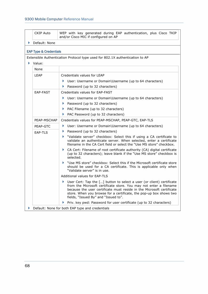
68
9300 Mobile Computer Reference Manual
CKIP Auto WEP with key generated during EAP authentication, plus Cisco TKIP and/or Cisco MIC if configured on AP
Default: None
EAP Type & Credentials
Extensible Authentication Protocol type used for 802.1X authentication to AP
Value:
None
LEAP Credentials values for LEAP
User: Username or Domain\Username (up to 64 characters)
Password (up to 32 characters)
EAP-FAST Credentials values for EAP-FAST
User: Username or Domain\Username (up to 64 characters)
Password (up to 32 characters)
PAC Filename (up to 32 characters)
PAC Password (up to 32 characters)
PEAP-MSCHAP
PEAP-GTC
EAP-TLS
Credentials values for PEAP-MSCHAP, PEAP-GTC, EAP-TLS
User: Username or Domain\Username (up to 64 characters)
Password (up to 32 characters)
“Validate server” checkbox: Select this if using a CA certificate to validate an authenticate server. When selected, enter a certificate filename in the CA Cert field or select the “Use MS store” checkbox.
CA Cert: Filename of root certificate authority (CA) digital certificate (up to 32 characters); leave blank if the “Use MS store” checkbox is selected.
“Use MS store” checkbox: Select this if the Microsoft certificate store should be used for a CA certificate. This is applicable only when “Validate server” is in use.
Additional values for EAP-TLS
User Cert: Tap the […] button to select a user (or client) certificate from the Microsoft certificate store. You may not enter a filename because the user certificate must reside in the Microsoft certificate store. When you browse for a certificate, the pop-up box shows two fields, “Issued By” and “Issued to”.
Priv. key pwd: Password for user certificate (up to 32 characters)
Default: None for both EAP type and credentials
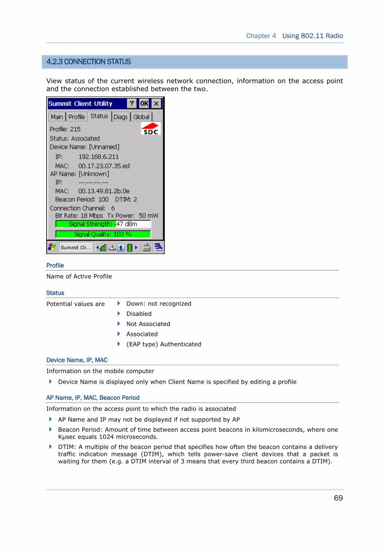
69
Chapter 4 Using 802.11 Radio
4.2.3 CONNECTION STATUS
View status of the current wireless network connection, information on the access point and the connection established between the two.
Profile
Name of Active Profile
Status
Potential values are Down: not recognized
Disabled
Not Associated
Associated
(EAP type) Authenticated
Device Name, IP, MAC
Information on the mobile computer
Device Name is displayed only when Client Name is specified by editing a profile
AP Name, IP, MAC, Beacon Period
Information on the access point to which the radio is associated
AP Name and IP may not be displayed if not supported by AP
Beacon Period: Amount of time between access point beacons in kilomicroseconds, where one Kµsec equals 1024 microseconds.
DTIM: A multiple of the beacon period that specifies how often the beacon contains a delivery traffic indication message (DTIM), which tells power-save client devices that a packet is waiting for them (e.g. a DTIM interval of 3 means that every third beacon contains a DTIM).
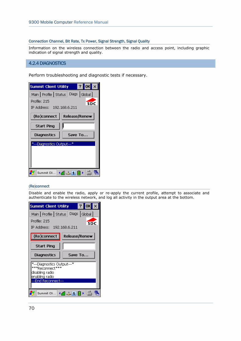
70
9300 Mobile Computer Reference Manual
Connection Channel, Bit Rate, Tx Power, Signal Strength, Signal Quality
Information on the wireless connection between the radio and access point, including graphic indication of signal strength and quality.
4.2.4 DIAGNOSTICS
Perform troubleshooting and diagnostic tests if necessary.
(Re)connect
Disable and enable the radio, apply or re-apply the current profile, attempt to associate and authenticate to the wireless network, and log all activity in the output area at the bottom.
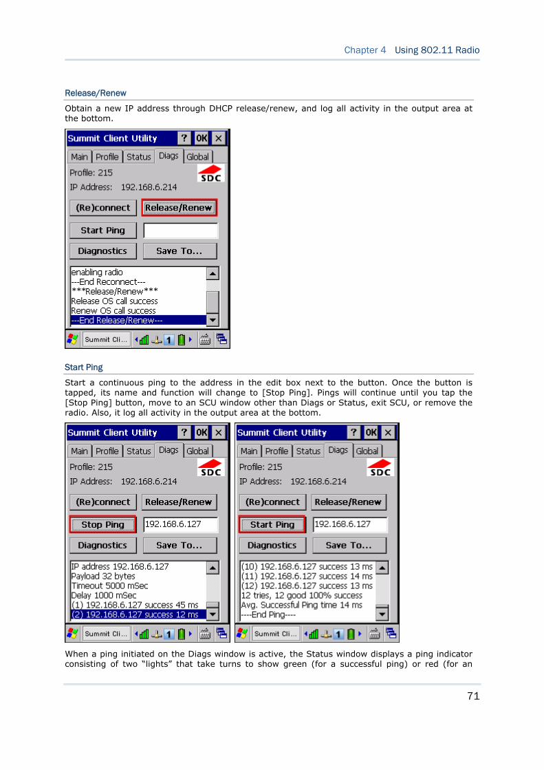
71
Chapter 4 Using 802.11 Radio
Release/Renew
Obtain a new IP address through DHCP release/renew, and log all activity in the output area at the bottom.
Start Ping
Start a continuous ping to the address in the edit box next to the button. Once the button is tapped, its name and function will change to [Stop Ping]. Pings will continue until you tap the [Stop Ping] button, move to an SCU window other than Diags or Status, exit SCU, or remove the radio. Also, it log all activity in the output area at the bottom.
When a ping initiated on the Diags window is active, the Status window displays a ping indicator consisting of two “lights” that take turns to show green (for a successful ping) or red (for an
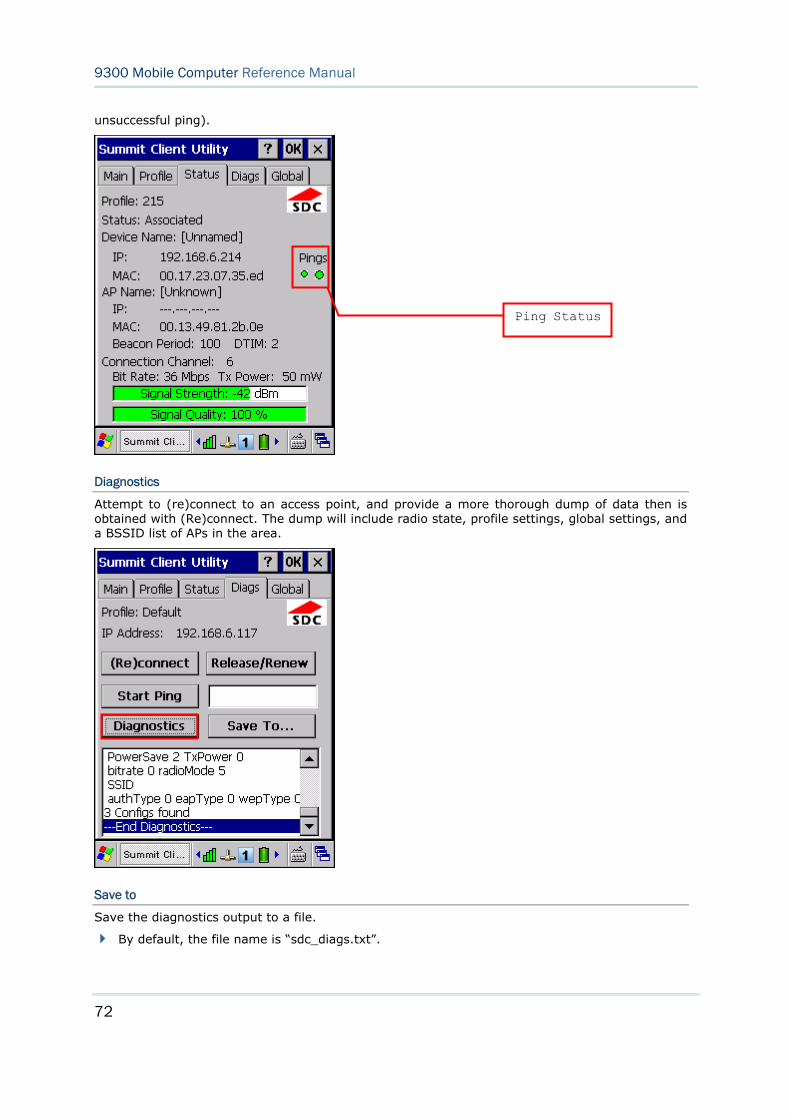
72
9300 Mobile Computer Reference Manual
unsuccessful ping).
Diagnostics
Attempt to (re)connect to an access point, and provide a more thorough dump of data then is obtained with (Re)connect. The dump will include radio state, profile settings, global settings, and a BSSID list of APs in the area.
Save to
Save the diagnostics output to a file.
By default, the file name is “sdc_diags.txt”.
Ping Status
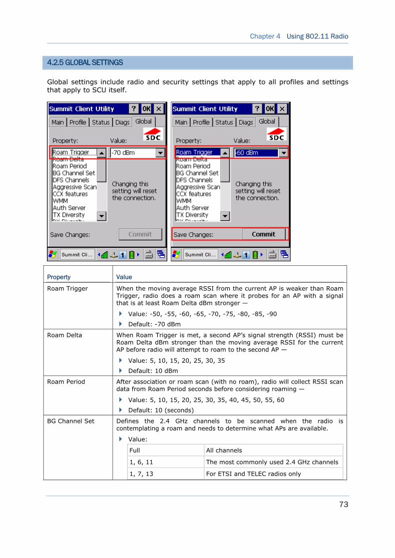
73
Chapter 4 Using 802.11 Radio
4.2.5 GLOBAL SETTINGS
Global settings include radio and security settings that apply to all profiles and settings that apply to SCU itself.
Property Value
Roam Trigger When the moving average RSSI from the current AP is weaker than Roam Trigger, radio does a roam scan where it probes for an AP with a signal that is at least Roam Delta dBm stronger —
Value: -50, -55, -60, -65, -70, -75, -80, -85, -90
Default: -70 dBm
Roam Delta When Roam Trigger is met, a second AP’s signal strength (RSSI) must be Roam Delta dBm stronger than the moving average RSSI for the current AP before radio will attempt to roam to the second AP —
Value: 5, 10, 15, 20, 25, 30, 35
Default: 10 dBm
Roam Period After association or roam scan (with no roam), radio will collect RSSI scan data from Roam Period seconds before considering roaming —
Value: 5, 10, 15, 20, 25, 30, 35, 40, 45, 50, 55, 60
Default: 10 (seconds)
BG Channel Set Defines the 2.4 GHz channels to be scanned when the radio is contemplating a roam and needs to determine what APs are available.
Value:
Full All channels
1, 6, 11 The most commonly used 2.4 GHz channels
1, 7, 13 For ETSI and TELEC radios only
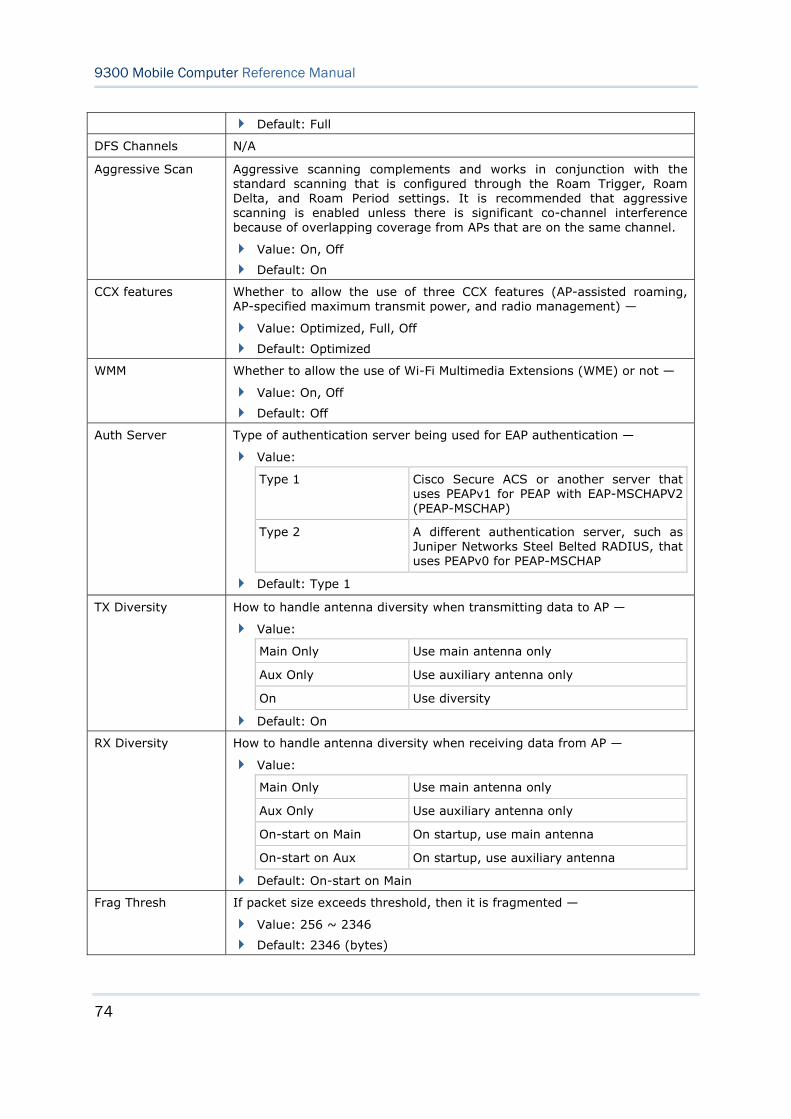
74
9300 Mobile Computer Reference Manual
Default: Full
DFS Channels N/A
Aggressive Scan Aggressive scanning complements and works in conjunction with the standard scanning that is configured through the Roam Trigger, Roam Delta, and Roam Period settings. It is recommended that aggressive scanning is enabled unless there is significant co-channel interference because of overlapping coverage from APs that are on the same channel.
Value: On, Off
Default: On
CCX features Whether to allow the use of three CCX features (AP-assisted roaming, AP-specified maximum transmit power, and radio management) —
Value: Optimized, Full, Off
Default: Optimized
WMM Whether to allow the use of Wi-Fi Multimedia Extensions (WME) or not —
Value: On, Off
Default: Off
Auth Server Type of authentication server being used for EAP authentication —
Value:
Type 1 Cisco Secure ACS or another server that uses PEAPv1 for PEAP with EAP-MSCHAPV2 (PEAP-MSCHAP)
Type 2 A different authentication server, such as Juniper Networks Steel Belted RADIUS, that uses PEAPv0 for PEAP-MSCHAP
Default: Type 1
TX Diversity How to handle antenna diversity when transmitting data to AP —
Value:
Main Only Use main antenna only
Aux Only Use auxiliary antenna only
On Use diversity
Default: On
RX Diversity How to handle antenna diversity when receiving data from AP —
Value:
Main Only Use main antenna only
Aux Only Use auxiliary antenna only
On-start on Main On startup, use main antenna
On-start on Aux On startup, use auxiliary antenna
Default: On-start on Main
Frag Thresh If packet size exceeds threshold, then it is fragmented —
Value: 256 ~ 2346
Default: 2346 (bytes)
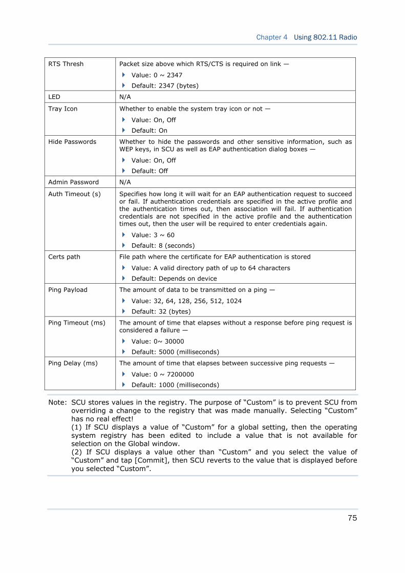
75
Chapter 4 Using 802.11 Radio
RTS Thresh Packet size above which RTS/CTS is required on link —
Value: 0 ~ 2347
Default: 2347 (bytes)
LED N/A
Tray Icon Whether to enable the system tray icon or not —
Value: On, Off
Default: On
Hide Passwords Whether to hide the passwords and other sensitive information, such as WEP keys, in SCU as well as EAP authentication dialog boxes —
Value: On, Off
Default: Off
Admin Password N/A
Auth Timeout (s) Specifies how long it will wait for an EAP authentication request to succeed or fail. If authentication credentials are specified in the active profile and the authentication times out, then association will fail. If authentication credentials are not specified in the active profile and the authentication times out, then the user will be required to enter credentials again.
Value: 3 ~ 60
Default: 8 (seconds)
Certs path File path where the certificate for EAP authentication is stored
Value: A valid directory path of up to 64 characters
Default: Depends on device
Ping Payload The amount of data to be transmitted on a ping —
Value: 32, 64, 128, 256, 512, 1024
Default: 32 (bytes)
Ping Timeout (ms) The amount of time that elapses without a response before ping request is considered a failure —
Value: 0~ 30000
Default: 5000 (milliseconds)
Ping Delay (ms) The amount of time that elapses between successive ping requests —
Value: 0 ~ 7200000
Default: 1000 (milliseconds)
Note: SCU stores values in the registry. The purpose of “Custom” is to prevent SCU from overriding a change to the registry that was made manually. Selecting “Custom” has no real effect! (1) If SCU displays a value of “Custom” for a global setting, then the operating system registry has been edited to include a value that is not available for selection on the Global window. (2) If SCU displays a value other than “Custom” and you select the value of “Custom” and tap [Commit], then SCU reverts to the value that is displayed before you selected “Custom”.
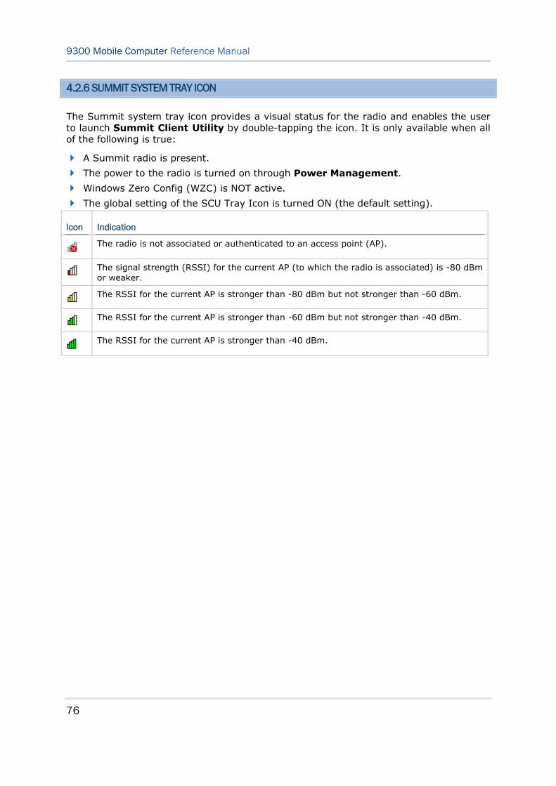
76
9300 Mobile Computer Reference Manual
4.2.6 SUMMIT SYSTEM TRAY ICON
The Summit system tray icon provides a visual status for the radio and enables the user to launch Summit Client Utility by double-tapping the icon. It is only available when all of the following is true:
A Summit radio is present.
The power to the radio is turned on through Power Management.
Windows Zero Config (WZC) is NOT active.
The global setting of the SCU Tray Icon is turned ON (the default setting).
Icon Indication
The radio is not associated or authenticated to an access point (AP).
The signal strength (RSSI) for the current AP (to which the radio is associated) is -80 dBm or weaker.
The RSSI for the current AP is stronger than -80 dBm but not stronger than -60 dBm.
The RSSI for the current AP is stronger than -60 dBm but not stronger than -40 dBm.
The RSSI for the current AP is stronger than -40 dBm.
77
Bluetooth Manager lets you configure Bluetooth settings and use Bluetooth services provided on the remote devices.
Warning: Bluetooth connection is maintained even in suspend mode. In order to prevent a cold boot after the battery is drained out, we suggest that you keep a fresh battery for replacement or connect the mobile computer to an external power.
IN THIS CHAPTER
5.1 Turn on Bluetooth Power............................................. 78 5.2 Search Devices.......................................................... 81 5.3 Pair Devices .............................................................. 82 5.4 File Transfer.............................................................. 87 5.5 Object Push .............................................................. 89 5.6 Serial Port Service ..................................................... 90 5.7 Manage Local Services................................................ 94
Chapter 5 USING BLUETOOTH
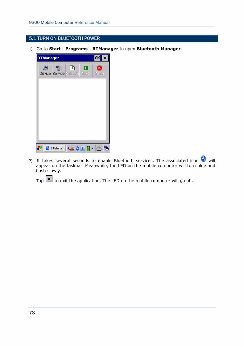
78
9300 Mobile Computer Reference Manual
5.1 TURN ON BLUETOOTH POWER
1) Go to Start | Programs | BTManager to open Bluetooth Manager.
2) It takes several seconds to enable Bluetooth services. The associated icon will appear on the taskbar. Meanwhile, the LED on the mobile computer will turn blue and flash slowly.
Tap to exit the application. The LED on the mobile computer will go off.
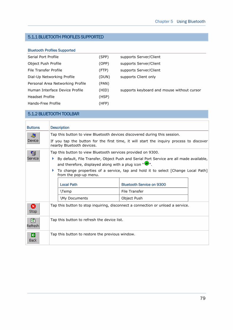
79
Chapter 5 Using Bluetooth
5.1.1 BLUETOOTH PROFILES SUPPORTED
Bluetooth Profiles Supported
Serial Port Profile (SPP) supports Server/Client
Object Push Profile (OPP) supports Server/Client
File Transfer Profile (FTP) supports Server/Client
Dial-Up Networking Profile (DUN) supports Client only
Personal Area Networking Profile (PAN)
Human Interface Device Profile (HID) supports keyboard and mouse without cursor
Headset Profile (HSP)
Hands-Free Profile (HFP)
5.1.2 BLUETOOTH TOOLBAR
Buttons Description
Tap this button to view Bluetooth devices discovered during this session.
If you tap the button for the first time, it will start the inquiry process to discover nearby Bluetooth devices.
Tap this button to view Bluetooth services provided on 9300.
By default, File Transfer, Object Push and Serial Port Service are all made available,
and therefore, displayed along with a plug icon “ ”.
To change properties of a service, tap and hold it to select [Change Local Path] from the pop-up menu.
Local Path Bluetooth Service on 9300
\Temp File Transfer
\My Documents Object Push
Tap this button to stop inquiring, disconnect a connection or unload a service.
Tap this button to refresh the device list.
Tap this button to restore the previous window.
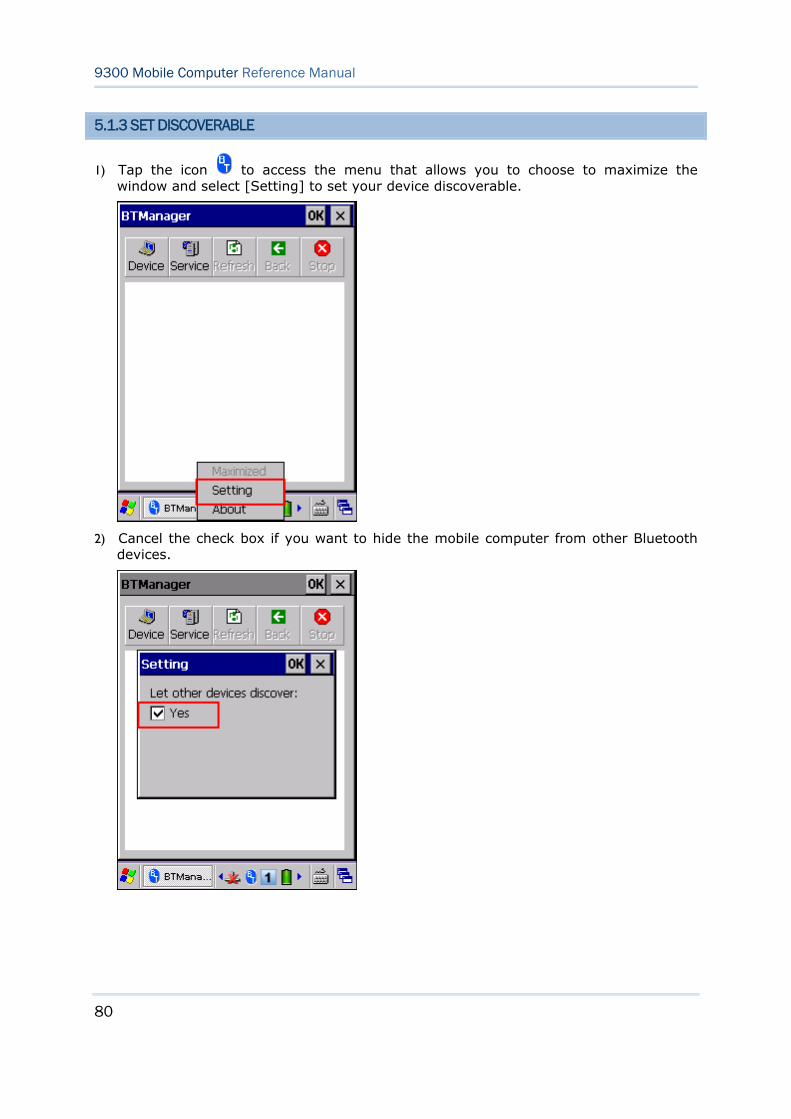
80
9300 Mobile Computer Reference Manual
5.1.3 SET DISCOVERABLE
1) Tap the icon to access the menu that allows you to choose to maximize the window and select [Setting] to set your device discoverable.
2) Cancel the check box if you want to hide the mobile computer from other Bluetooth devices.
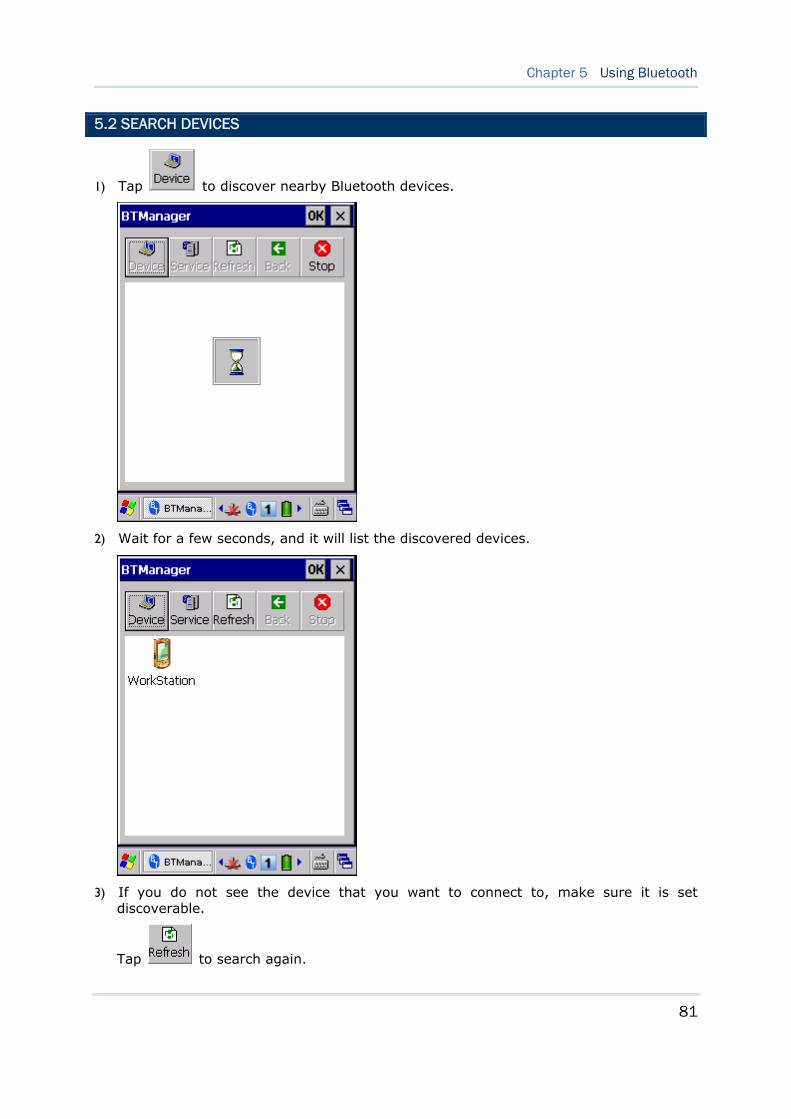
81
Chapter 5 Using Bluetooth
5.2 SEARCH DEVICES
1) Tap to discover nearby Bluetooth devices.
2) Wait for a few seconds, and it will list the discovered devices.
3) If you do not see the device that you want to connect to, make sure it is set discoverable.
Tap to search again.
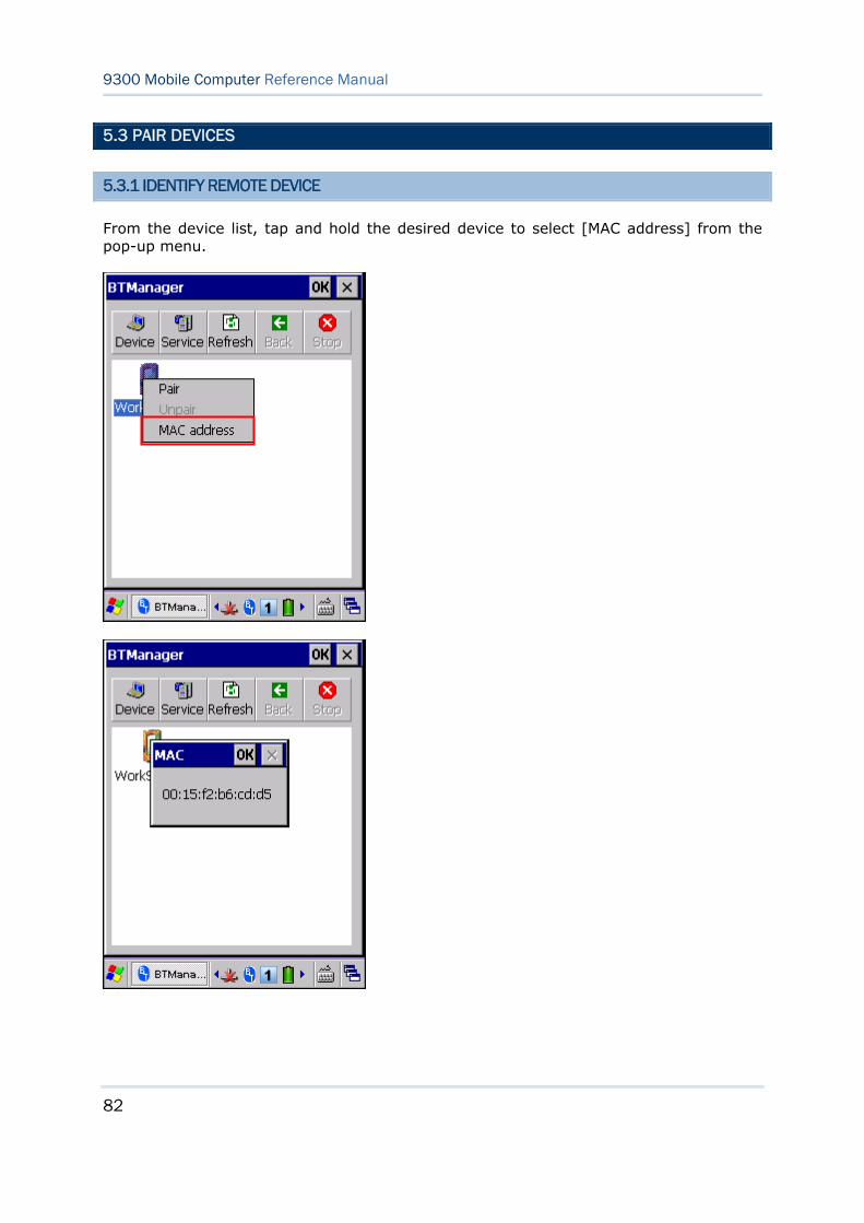
82
9300 Mobile Computer Reference Manual
5.3 PAIR DEVICES
5.3.1 IDENTIFY REMOTE DEVICE
From the device list, tap and hold the desired device to select [MAC address] from the pop-up menu.
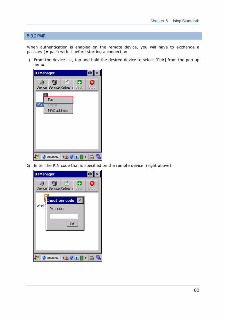
83
Chapter 5 Using Bluetooth
5.3.2 PAIR
When authentication is enabled on the remote device, you will have to exchange a passkey (= pair) with it before starting a connection.
1) From the device list, tap and hold the desired device to select [Pair] from the pop-up menu.
2) Enter the PIN code that is specified on the remote device. (right above)
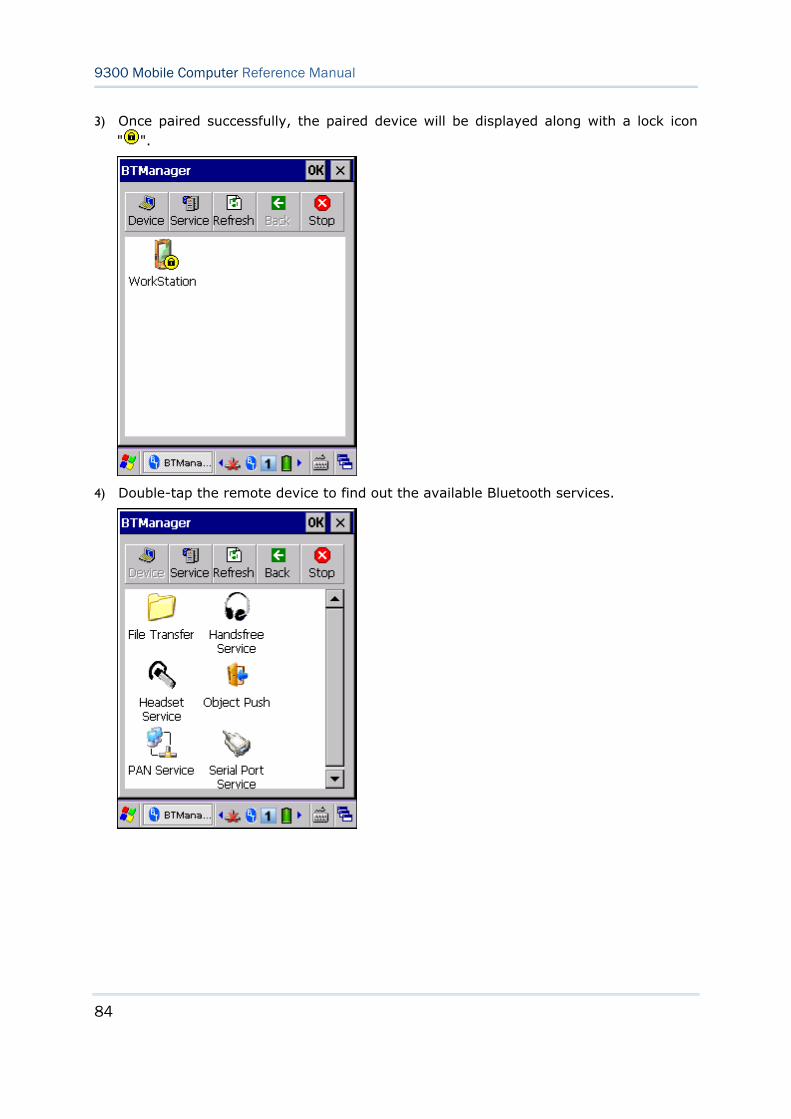
84
9300 Mobile Computer Reference Manual
3) Once paired successfully, the paired device will be displayed along with a lock icon " ".
4) Double-tap the remote device to find out the available Bluetooth services.
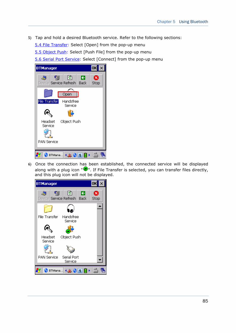
85
Chapter 5 Using Bluetooth
5) Tap and hold a desired Bluetooth service. Refer to the following sections:
5.4 File Transfer: Select [Open] from the pop-up menu
5.5 Object Push: Select [Push File] from the pop-up menu
5.6 Serial Port Service: Select [Connect] from the pop-up menu
6) Once the connection has been established, the connected service will be displayed along with a plug icon " ". If File Transfer is selected, you can transfer files directly, and this plug icon will not be displayed.

86
9300 Mobile Computer Reference Manual
5.3.3 UNPAIR
From the device list, tap and hold the desired device to select [Unpair] from the pop-up menu.
Note: The mobile computer must be unpaired on the remote device as well. For example, remove it from the device list on PC. (Both devices must be unpaired!)
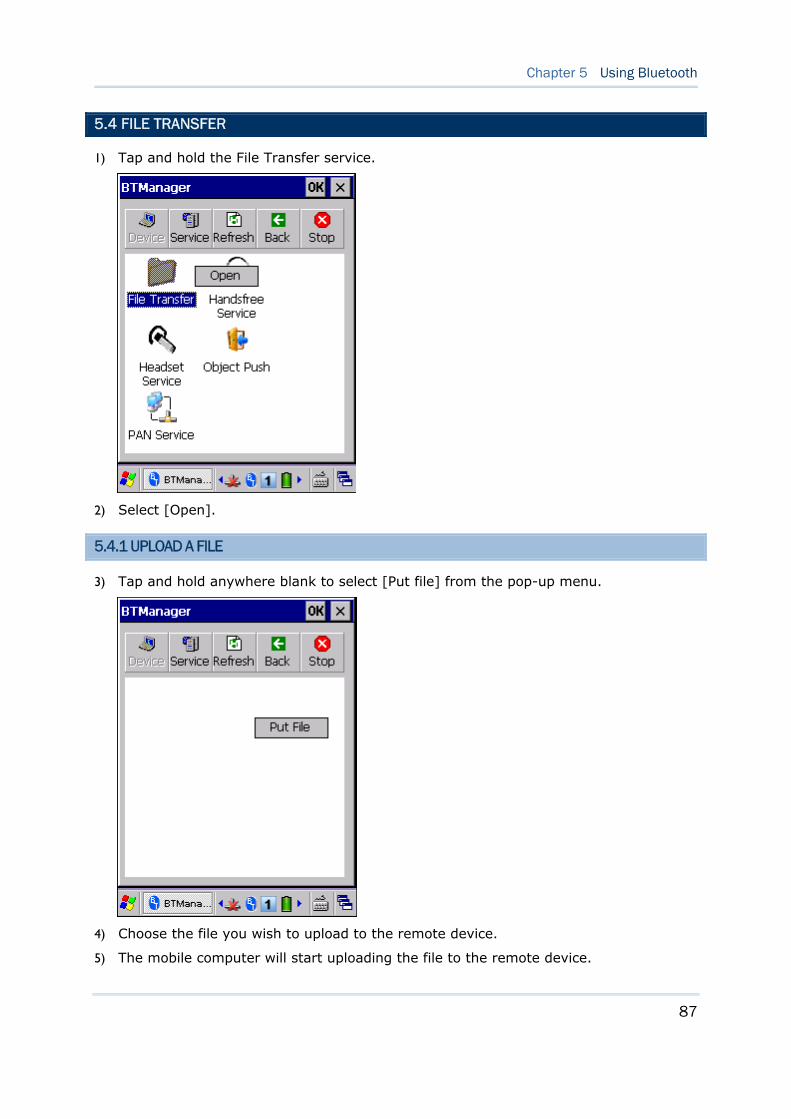
87
Chapter 5 Using Bluetooth
5.4 FILE TRANSFER
1) Tap and hold the File Transfer service.
2) Select [Open].
5.4.1 UPLOAD A FILE
3) Tap and hold anywhere blank to select [Put file] from the pop-up menu.
4) Choose the file you wish to upload to the remote device.
5) The mobile computer will start uploading the file to the remote device.
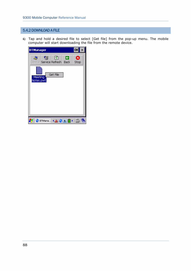
88
9300 Mobile Computer Reference Manual
5.4.2 DOWNLOAD A FILE
6) Tap and hold a desired file to select [Get file] from the pop-up menu. The mobile computer will start downloading the file from the remote device.
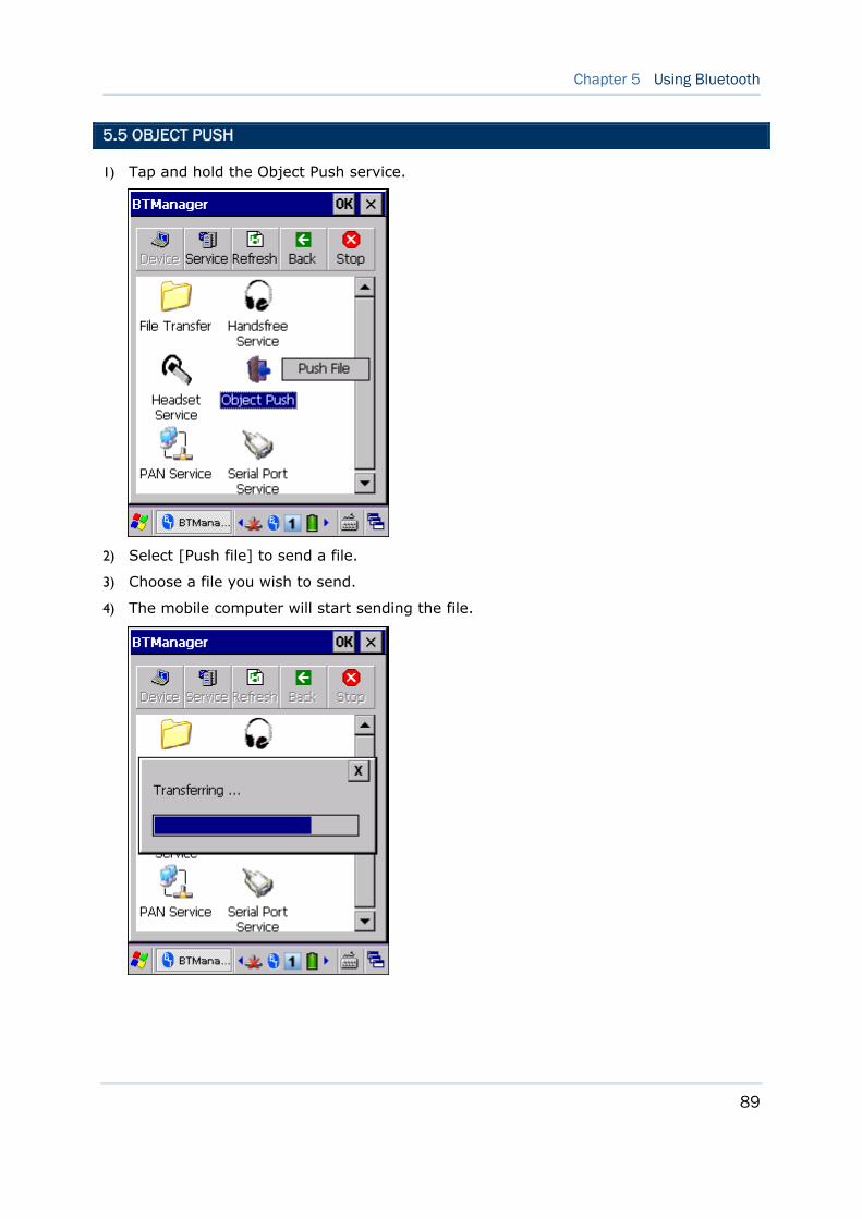
89
Chapter 5 Using Bluetooth
5.5 OBJECT PUSH
1) Tap and hold the Object Push service.
2) Select [Push file] to send a file.
3) Choose a file you wish to send.
4) The mobile computer will start sending the file.
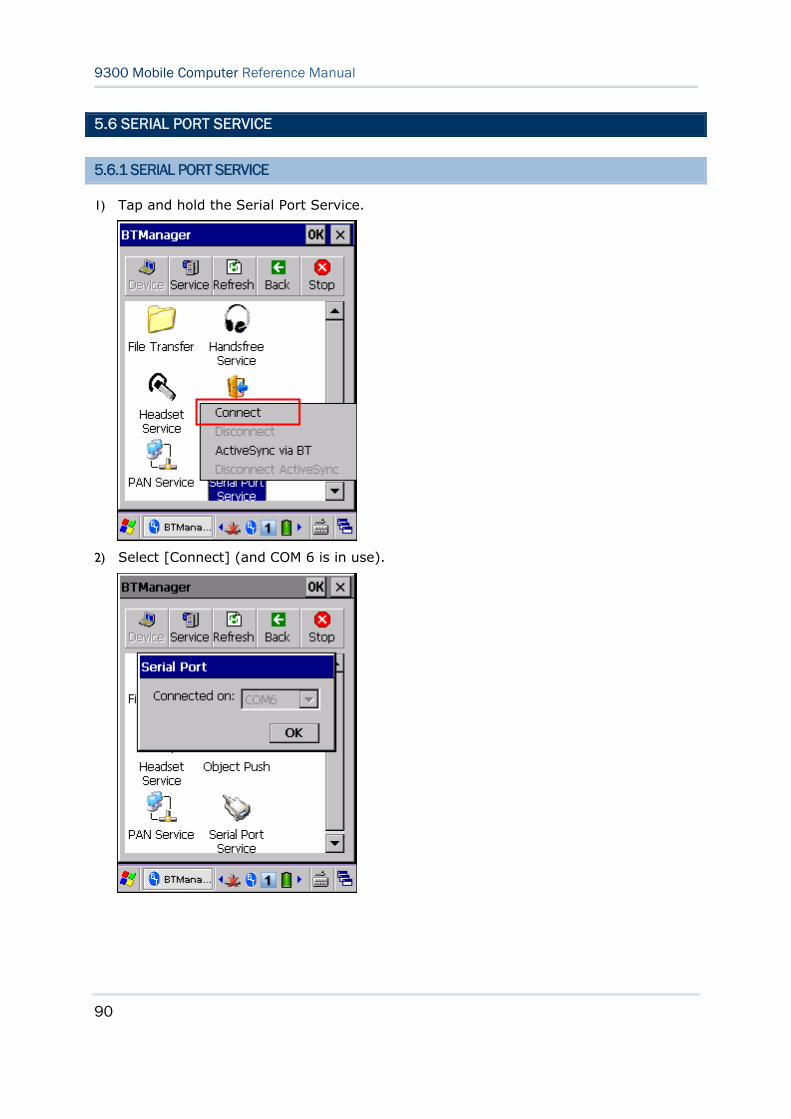
90
9300 Mobile Computer Reference Manual
5.6 SERIAL PORT SERVICE
5.6.1 SERIAL PORT SERVICE
1) Tap and hold the Serial Port Service.
2) Select [Connect] (and COM 6 is in use).
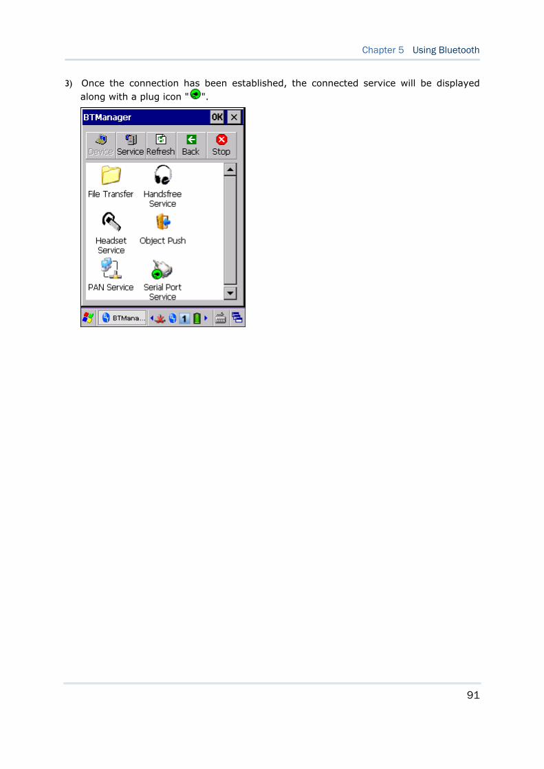
91
Chapter 5 Using Bluetooth
3) Once the connection has been established, the connected service will be displayed along with a plug icon " ".
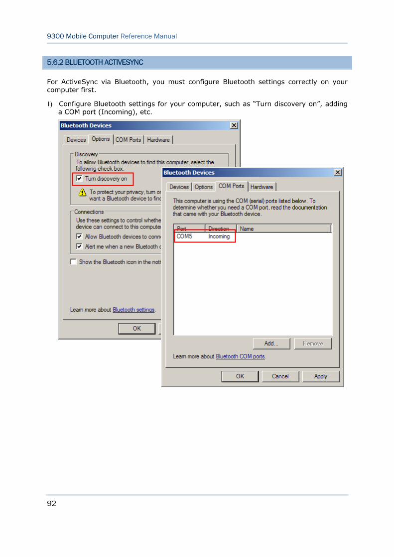
92
9300 Mobile Computer Reference Manual
5.6.2 BLUETOOTH ACTIVESYNC
For ActiveSync via Bluetooth, you must configure Bluetooth settings correctly on your computer first.
1) Configure Bluetooth settings for your computer, such as “Turn discovery on”, adding a COM port (Incoming), etc.
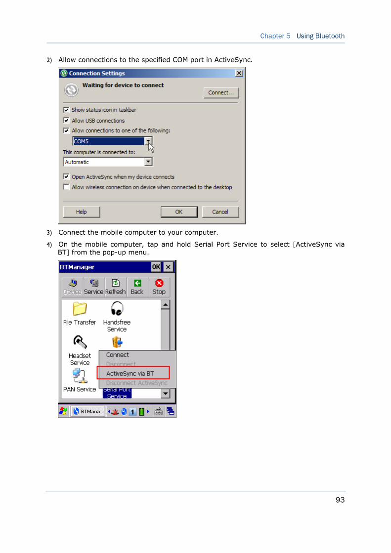
93
Chapter 5 Using Bluetooth
2) Allow connections to the specified COM port in ActiveSync.
3) Connect the mobile computer to your computer.
4) On the mobile computer, tap and hold Serial Port Service to select [ActiveSync via BT] from the pop-up menu.
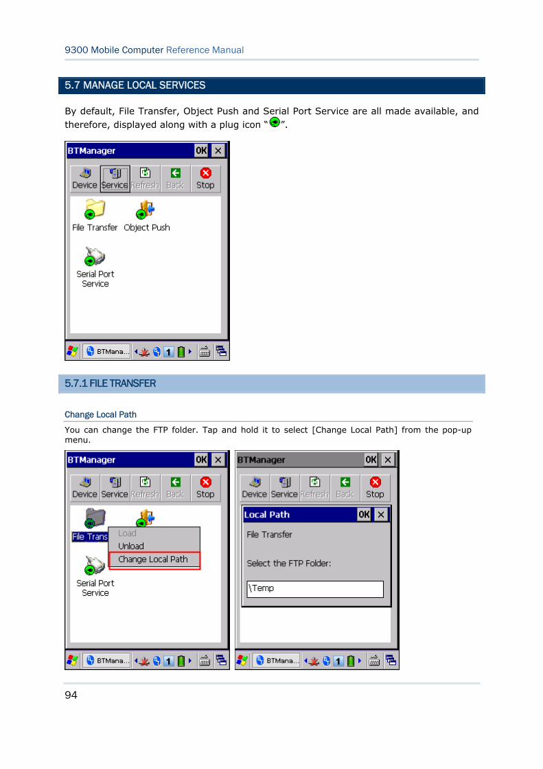
94
9300 Mobile Computer Reference Manual
5.7 MANAGE LOCAL SERVICES
By default, File Transfer, Object Push and Serial Port Service are all made available, and therefore, displayed along with a plug icon “ ”.
5.7.1 FILE TRANSFER
Change Local Path
You can change the FTP folder. Tap and hold it to select [Change Local Path] from the pop-up menu.
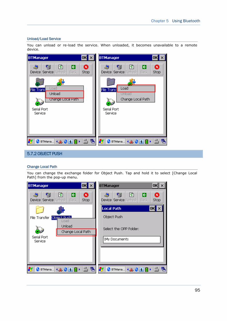
95
Chapter 5 Using Bluetooth
Unload/Load Service
You can unload or re-load the service. When unloaded, it becomes unavailable to a remote device.
5.7.2 OBJECT PUSH
Change Local Path
You can change the exchange folder for Object Push. Tap and hold it to select [Change Local Path] from the pop-up menu.
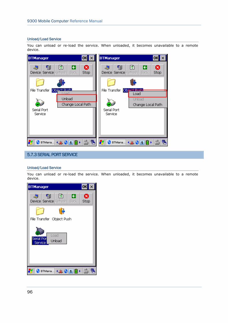
96
9300 Mobile Computer Reference Manual
Unload/Load Service
You can unload or re-load the service. When unloaded, it becomes unavailable to a remote device.
5.7.3 SERIAL PORT SERVICE
Unload/Load Service
You can unload or re-load the service. When unloaded, it becomes unavailable to a remote device.

97
Reader Configuration Utility is the tool that lets you manage the barcode reader on the mobile computer.
IN THIS CHAPTER
6.1 Run ReaderConfig.exe ................................................ 97 6.2 Barcode Reader Settings............................................. 99 6.3 Data Output.............................................................100 6.4 Notifications (for Good Read)......................................102 6.5 Symbology Settings ..................................................103
6.1 RUN READERCONFIG.EXE
1) Go to Start | Programs | ReaderConfig to open the Reader Configuration
Utility. The associated icon will appear on the taskbar.
Chapter 6 USING READER CONFIGURATION UTILITY
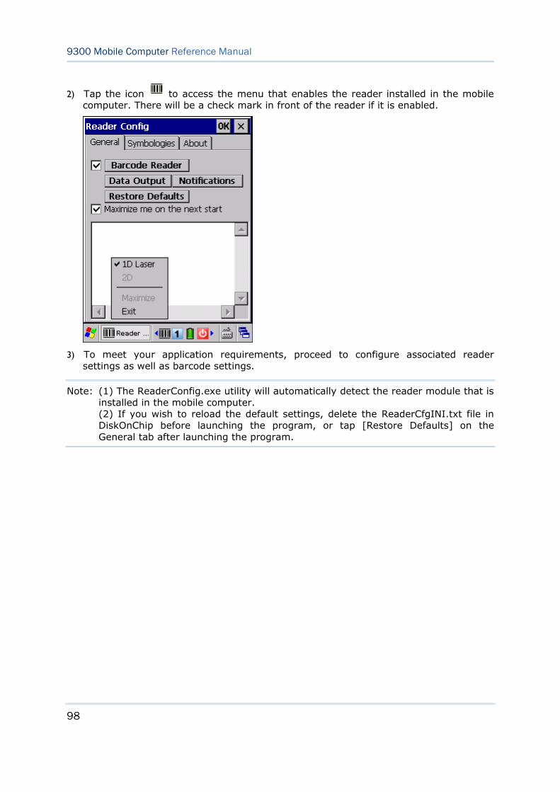
98
9300 Mobile Computer Reference Manual
2) Tap the icon to access the menu that enables the reader installed in the mobile computer. There will be a check mark in front of the reader if it is enabled.
3) To meet your application requirements, proceed to configure associated reader settings as well as barcode settings.
Note: (1) The ReaderConfig.exe utility will automatically detect the reader module that is installed in the mobile computer. (2) If you wish to reload the default settings, delete the ReaderCfgINI.txt file in DiskOnChip before launching the program, or tap [Restore Defaults] on the General tab after launching the program.
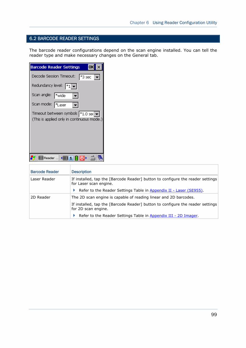
99
Chapter 6 Using Reader Configuration Utility
6.2 BARCODE READER SETTINGS
The barcode reader configurations depend on the scan engine installed. You can tell the reader type and make necessary changes on the General tab.
Barcode Reader Description
Laser Reader If installed, tap the [Barcode Reader] button to configure the reader settings for Laser scan engine.
Refer to the Reader Settings Table in Appendix II - Laser (SE955).
2D Reader The 2D scan engine is capable of reading linear and 2D barcodes.
If installed, tap the [Barcode Reader] button to configure the reader settings for 2D scan engine.
Refer to the Reader Settings Table in Appendix III - 2D Imager.
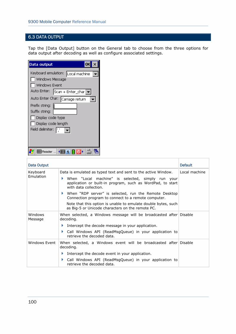
100
9300 Mobile Computer Reference Manual
6.3 DATA OUTPUT
Tap the [Data Output] button on the General tab to choose from the three options for data output after decoding as well as configure associated settings.
Data Output Default
Keyboard Emulation
Data is emulated as typed text and sent to the active Window.
When “Local machine” is selected, simply run your application or built-in program, such as WordPad, to start with data collection.
When “RDP server” is selected, run the Remote Desktop Connection program to connect to a remote computer.
Note that this option is unable to emulate double bytes, such as Big-5 or Unicode characters on the remote PC.
Local machine
Windows Message
When selected, a Windows message will be broadcasted after decoding.
Intercept the decode message in your application.
Call Windows API (ReadMsgQueue) in your application to retrieve the decoded data.
Disable
Windows Event When selected, a Windows event will be broadcasted after decoding.
Intercept the decode event in your application.
Call Windows API (ReadMsgQueue) in your application to retrieve the decoded data.
Disable
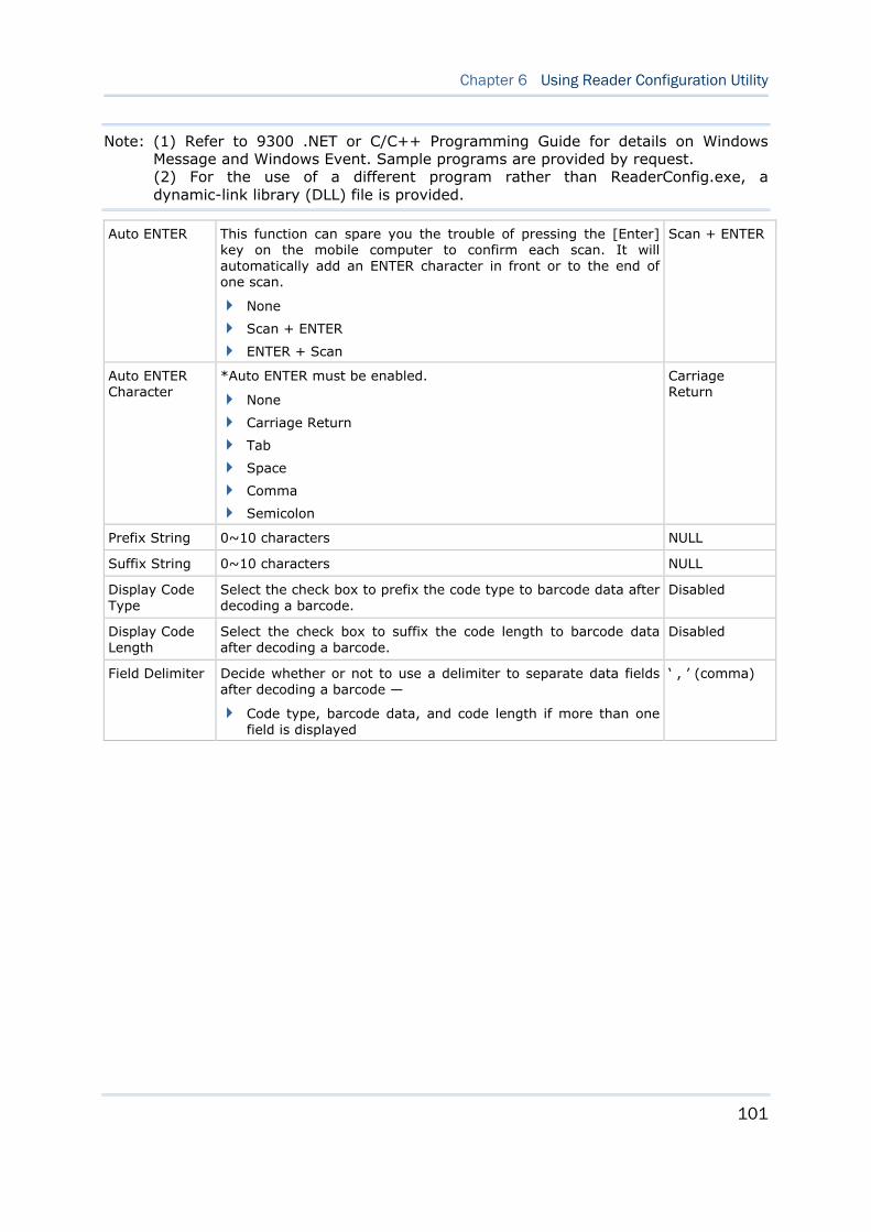
101
Chapter 6 Using Reader Configuration Utility
Note: (1) Refer to 9300 .NET or C/C++ Programming Guide for details on Windows Message and Windows Event. Sample programs are provided by request. (2) For the use of a different program rather than ReaderConfig.exe, a dynamic-link library (DLL) file is provided.
Auto ENTER This function can spare you the trouble of pressing the [Enter] key on the mobile computer to confirm each scan. It will automatically add an ENTER character in front or to the end of one scan.
None
Scan + ENTER
ENTER + Scan
Scan + ENTER
Auto ENTER Character
*Auto ENTER must be enabled.
None
Carriage Return
Tab
Space
Comma
Semicolon
Carriage Return
Prefix String 0~10 characters NULL
Suffix String 0~10 characters NULL
Display Code Type
Select the check box to prefix the code type to barcode data after decoding a barcode.
Disabled
Display Code Length
Select the check box to suffix the code length to barcode data after decoding a barcode.
Disabled
Field Delimiter Decide whether or not to use a delimiter to separate data fields after decoding a barcode —
Code type, barcode data, and code length if more than one field is displayed
‘ , ’ (comma)
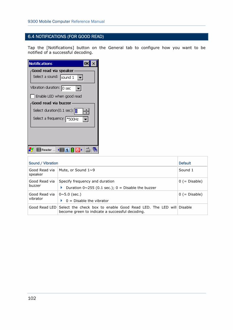
102
9300 Mobile Computer Reference Manual
6.4 NOTIFICATIONS (FOR GOOD READ)
Tap the [Notifications] button on the General tab to configure how you want to be notified of a successful decoding.
Sound / Vibration Default
Good Read via speaker
Mute, or Sound 1~9 Sound 1
Good Read via buzzer
Specify frequency and duration
Duration 0~255 (0.1 sec.); 0 = Disable the buzzer
0 (= Disable)
Good Read via vibrator
0~5.0 (sec.)
0 = Disable the vibrator
0 (= Disable)
Good Read LED Select the check box to enable Good Read LED. The LED will become green to indicate a successful decoding.
Disable
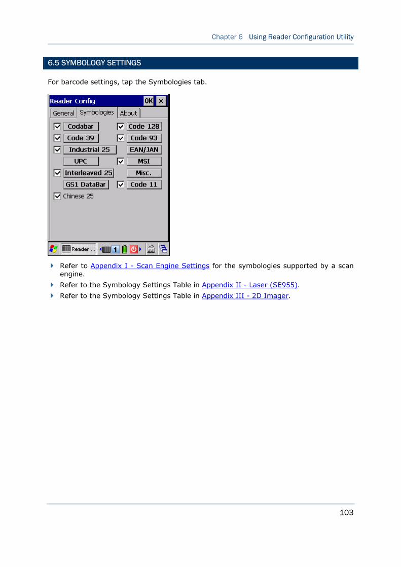
103
Chapter 6 Using Reader Configuration Utility
6.5 SYMBOLOGY SETTINGS
For barcode settings, tap the Symbologies tab.
Refer to Appendix I - Scan Engine Settings for the symbologies supported by a scan engine.
Refer to the Symbology Settings Table in Appendix II - Laser (SE955).
Refer to the Symbology Settings Table in Appendix III - 2D Imager.

104
9300 Mobile Computer Reference Manual
105
9300 Mobile Computer provides several utilities and applications which are made accessible from START | Programs.
Backup Utility lets you manipulate the way to backup programs and data.
Button Assignment Utility lets you assign a specific button as a hot key for launching a program or performing a certain action.
Screen Control Utility lets you change the screen orientation.
IN THIS CHAPTER
7.1 Backup Utility...........................................................105 7.2 Button Assignment Utility...........................................112 7.3 Screen Control .........................................................115
7.1 BACKUP UTILITY
The CipherLab Backup Utility is provided to help you easily make copies of data and restore your mobile computer's specific registry settings, install applications, user data, etc. You may use the backups (.bkp) for these purposes:
Full Restore Operation
Backup all necessary files here (you don't have to select "Registry") so that you can restore your mobile computer to an operational state following a disaster.
Partial Restore Operation
Backup a few specific files here so that you can restore small numbers of files after you have deleted them by accident or found them corrupted.
Easy Cloning
Backup everything (including "Registry") necessary for cloning settings to other 9300 Mobile Computers.
Chapter 7 MORE APPLICATIONS
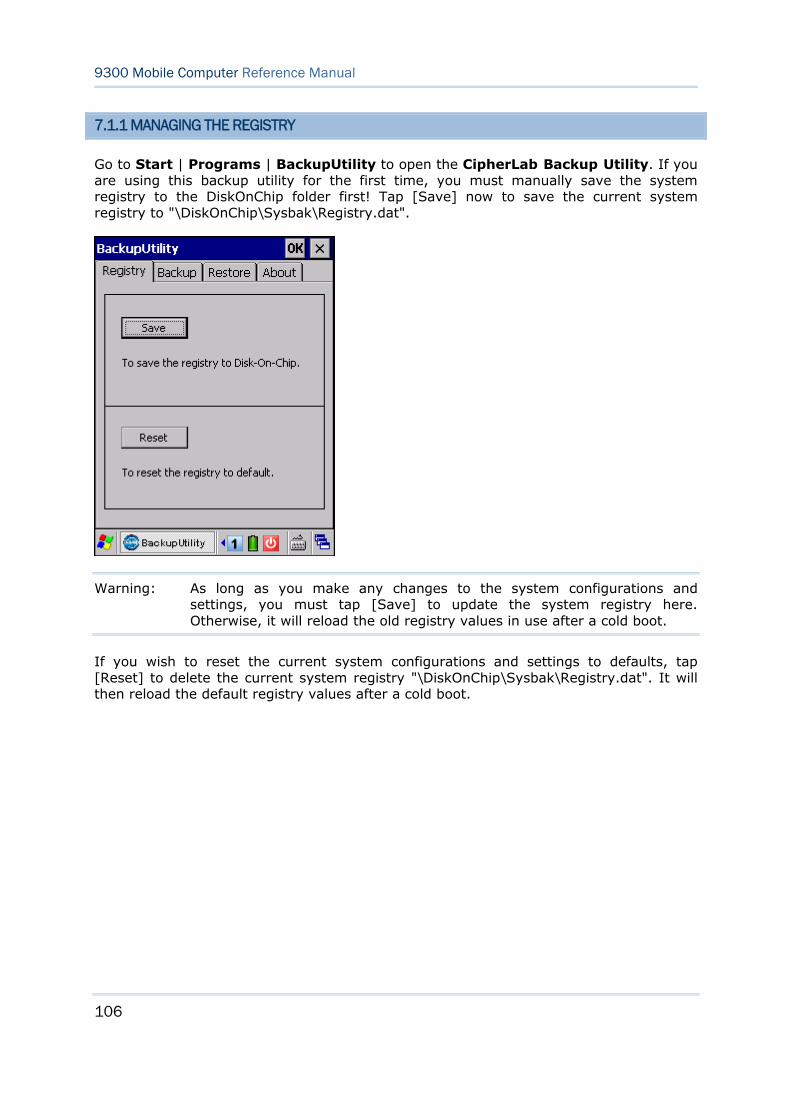
106
9300 Mobile Computer Reference Manual
7.1.1 MANAGING THE REGISTRY
Go to Start | Programs | BackupUtility to open the CipherLab Backup Utility. If you are using this backup utility for the first time, you must manually save the system registry to the DiskOnChip folder first! Tap [Save] now to save the current system registry to "\DiskOnChip\Sysbak\Registry.dat".
Warning: As long as you make any changes to the system configurations and settings, you must tap [Save] to update the system registry here. Otherwise, it will reload the old registry values in use after a cold boot.
If you wish to reset the current system configurations and settings to defaults, tap [Reset] to delete the current system registry "\DiskOnChip\Sysbak\Registry.dat". It will then reload the default registry values after a cold boot.
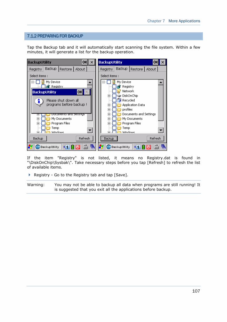
107
Chapter 7 More Applications
7.1.2 PREPARING FOR BACKUP
Tap the Backup tab and it will automatically start scanning the file system. Within a few minutes, it will generate a list for the backup operation.
If the item "Registry" is not listed, it means no Registry.dat is found in "\DiskOnChip\Sysbak\". Take necessary steps before you tap [Refresh] to refresh the list of available items.
Registry - Go to the Registry tab and tap [Save].
Warning: You may not be able to backup all data when programs are still running! It is suggested that you exit all the applications before backup.
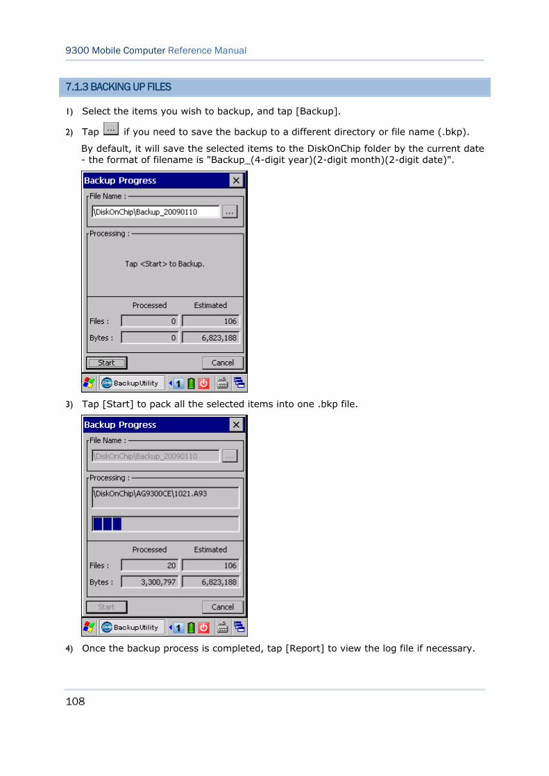
108
9300 Mobile Computer Reference Manual
7.1.3 BACKING UP FILES
1) Select the items you wish to backup, and tap [Backup].
2) Tap if you need to save the backup to a different directory or file name (.bkp).
By default, it will save the selected items to the DiskOnChip folder by the current date - the format of filename is "Backup_(4-digit year)(2-digit month)(2-digit date)".
3) Tap [Start] to pack all the selected items into one .bkp file.
4) Once the backup process is completed, tap [Report] to view the log file if necessary.
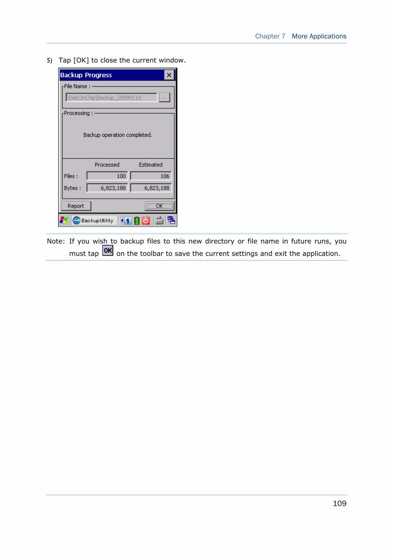
109
Chapter 7 More Applications
5) Tap [OK] to close the current window.
Note: If you wish to backup files to this new directory or file name in future runs, you
must tap on the toolbar to save the current settings and exit the application.
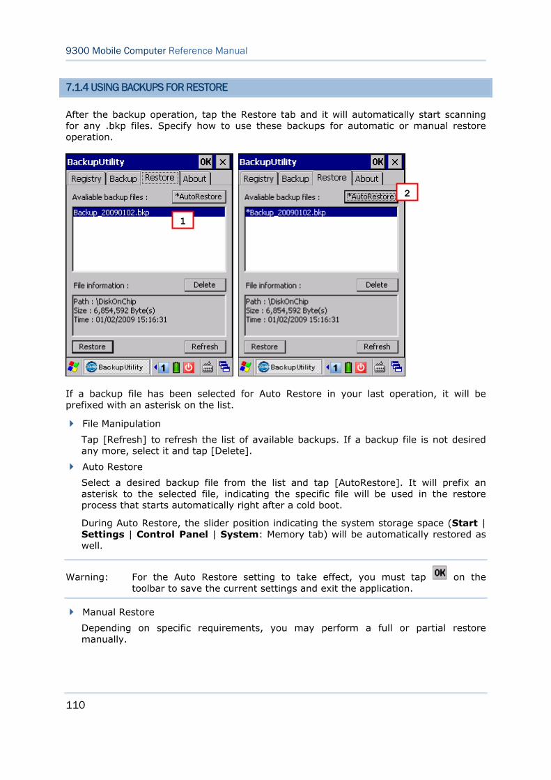
110
9300 Mobile Computer Reference Manual
7.1.4 USING BACKUPS FOR RESTORE
After the backup operation, tap the Restore tab and it will automatically start scanning for any .bkp files. Specify how to use these backups for automatic or manual restore operation.
If a backup file has been selected for Auto Restore in your last operation, it will be prefixed with an asterisk on the list.
File Manipulation
Tap [Refresh] to refresh the list of available backups. If a backup file is not desired any more, select it and tap [Delete].
Auto Restore
Select a desired backup file from the list and tap [AutoRestore]. It will prefix an asterisk to the selected file, indicating the specific file will be used in the restore process that starts automatically right after a cold boot.
During Auto Restore, the slider position indicating the system storage space (Start | Settings | Control Panel | System: Memory tab) will be automatically restored as well.
Warning: For the Auto Restore setting to take effect, you must tap on the toolbar to save the current settings and exit the application.
Manual Restore
Depending on specific requirements, you may perform a full or partial restore manually.
1
2
111
Chapter 7 More Applications
Full Restore Operation
1. Select a desired backup file from the list.
2. Tap [Restore].
3. Tap [Start] to run the restore process.
4. Once the restore process is completed, you will be asked to perform a warm boot. Tap [No] if you wish to warm boot later. You may tap [Report] to view the log file if necessary.
Partial Restore Operation
1. Double-tap a desired backup file from the list.
2. Select the desired items.
3. Tap [Restore].
4. Tap [Start] to run the restore process.
5. Once the restore process is completed, you will be asked to perform a warm boot. Tap [No] if you wish to warm boot later. You may tap [Report] to view the log file if necessary.
Warning: (1) You must perform a warm boot after the restore operation! (2) You may encounter insufficient memory for the restore operation and be asked to check memory space on the system (SDRAM), DiskOnChip or SD/MMC/SDHC card. If you insist on restoring it without deleting files, data loss or incomplete restore may occur.
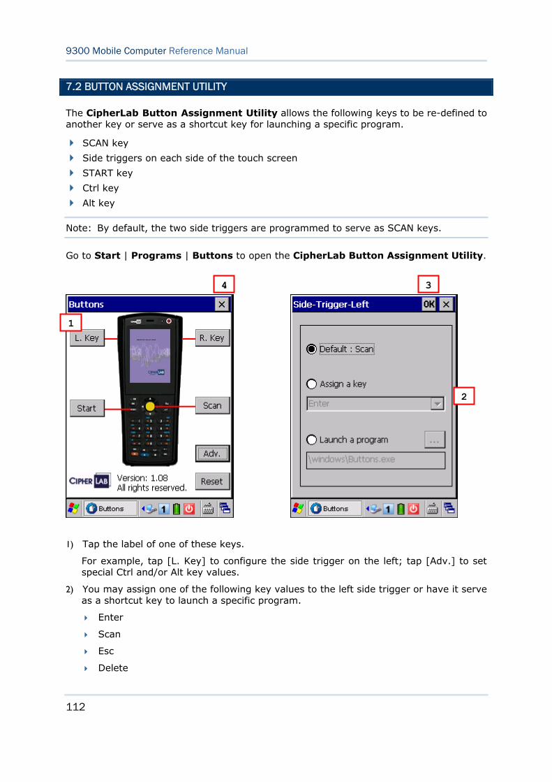
112
9300 Mobile Computer Reference Manual
7.2 BUTTON ASSIGNMENT UTILITY
The CipherLab Button Assignment Utility allows the following keys to be re-defined to another key or serve as a shortcut key for launching a specific program.
SCAN key
Side triggers on each side of the touch screen
START key
Ctrl key
Alt key
Note: By default, the two side triggers are programmed to serve as SCAN keys.
Go to Start | Programs | Buttons to open the CipherLab Button Assignment Utility.
1) Tap the label of one of these keys.
For example, tap [L. Key] to configure the side trigger on the left; tap [Adv.] to set special Ctrl and/or Alt key values.
2) You may assign one of the following key values to the left side trigger or have it serve as a shortcut key to launch a specific program.
Enter
Scan
Esc
Delete
1
2
3 4
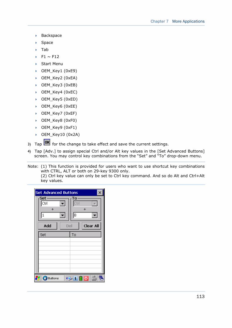
113
Chapter 7 More Applications
Backspace
Space
Tab
F1 ~ F12
Start Menu
OEM_Key1 (0xE9)
OEM_Key2 (0xEA)
OEM_Key3 (0xEB)
OEM_Key4 (0xEC)
OEM_Key5 (0xED)
OEM_Key6 (0xEE)
OEM_Key7 (0xEF)
OEM_Key8 (0xF0)
OEM_Key9 (0xF1)
OEM_Key10 (0x2A)
3) Tap for the change to take effect and save the current settings.
4) Tap [Adv.] to assign special Ctrl and/or Alt key values in the [Set Advanced Buttons] screen. You may control key combinations from the “Set” and “To” drop-down menu.
Note: (1) This function is provided for users who want to use shortcut key combinations with CTRL, ALT or both on 29-key 9300 only. (2) Ctrl key value can only be set to Ctrl key command. And so do Alt and Ctrl+Alt key values.
114
9300 Mobile Computer Reference Manual
5) You can set Ctrl, Alt or Ctrl+Alt keys combined with the following keys:
0 ~ 9
F1 ~ F12
For example, you may assign [Ctrl] key + number key [1] to act as shortcut key CTRL+C and [Ctrl] key + number key [2] to act as CTRL+V. Then, you will able to copy-and-past in applications like WordPad, as shown below.
In Alpha mode, press [Ctrl] key and number key [2] to select all. ( = CTRL+A)
In numeric mode, press [Ctrl] key and number key [1] to copy the selected area. (= CTRL+C)
In numeric mode, press [Ctrl] key and number key [2] to paste it. (= CTRL+V)
6) Tap [Add] to confirm each assignment. Key values you added will be listed in the field below. You can add eight key combinations at most. Tap [Del] or [Clear All] to remove a selected key combination or all settings in the list when needed.
7) Tap on the toolbar to exit the [Set Advanced Buttons] screen.
8) You may tap [Reset] to restore defaults.
9) Tap on the toolbar to exit the application.
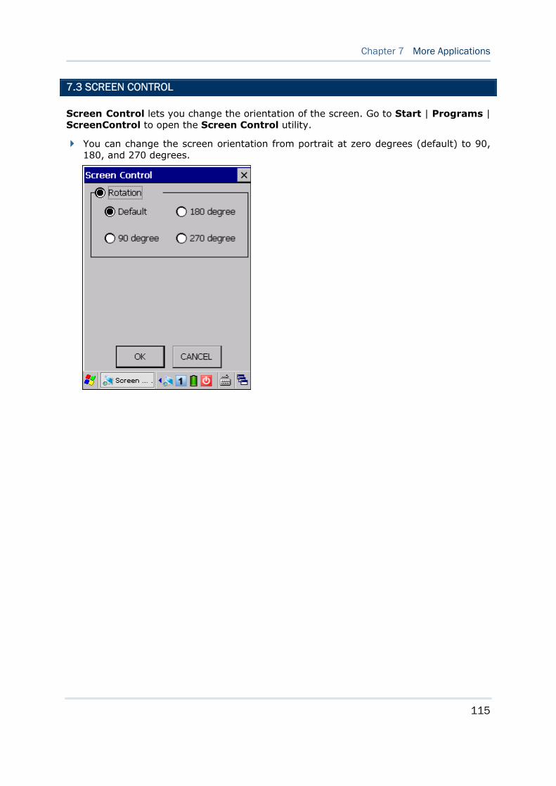
115
Chapter 7 More Applications
7.3 SCREEN CONTROL
Screen Control lets you change the orientation of the screen. Go to Start | Programs | ScreenControl to open the Screen Control utility.
You can change the screen orientation from portrait at zero degrees (default) to 90, 180, and 270 degrees.

116
9300 Mobile Computer Reference Manual
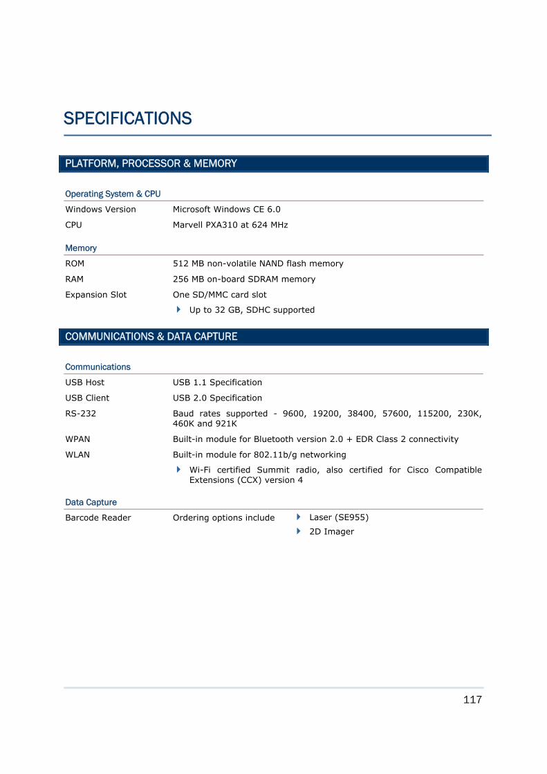
117
PLATFORM, PROCESSOR & MEMORY
Operating System & CPU
Windows Version Microsoft Windows CE 6.0
CPU Marvell PXA310 at 624 MHz
Memory
ROM 512 MB non-volatile NAND flash memory
RAM 256 MB on-board SDRAM memory
Expansion Slot One SD/MMC card slot
Up to 32 GB, SDHC supported
COMMUNICATIONS & DATA CAPTURE
Communications
USB Host USB 1.1 Specification
USB Client USB 2.0 Specification
RS-232 Baud rates supported - 9600, 19200, 38400, 57600, 115200, 230K, 460K and 921K
WPAN Built-in module for Bluetooth version 2.0 + EDR Class 2 connectivity
WLAN Built-in module for 802.11b/g networking
Wi-Fi certified Summit radio, also certified for Cisco Compatible Extensions (CCX) version 4
Data Capture
Barcode Reader Ordering options include
Laser (SE955)
2D Imager
SPECIFICATIONS
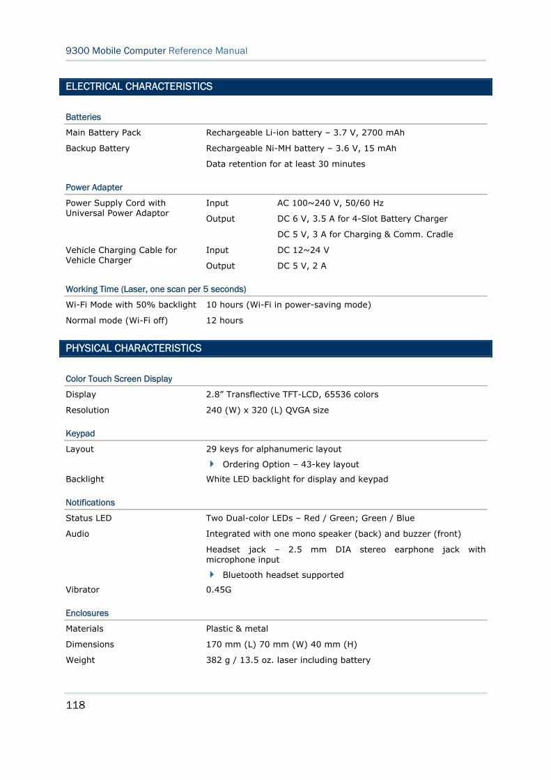
118
9300 Mobile Computer Reference Manual
ELECTRICAL CHARACTERISTICS
Batteries
Main Battery Pack Rechargeable Li-ion battery – 3.7 V, 2700 mAh
Backup Battery Rechargeable Ni-MH battery – 3.6 V, 15 mAh
Data retention for at least 30 minutes
Power Adapter
Input AC 100~240 V, 50/60 Hz Power Supply Cord with Universal Power Adaptor
Output DC 6 V, 3.5 A for 4-Slot Battery Charger
DC 5 V, 3 A for Charging & Comm. Cradle
Input DC 12~24 V Vehicle Charging Cable for Vehicle Charger
Output DC 5 V, 2 A
Working Time (Laser, one scan per 5 seconds)
Wi-Fi Mode with 50% backlight 10 hours (Wi-Fi in power-saving mode)
Normal mode (Wi-Fi off) 12 hours
PHYSICAL CHARACTERISTICS
Color Touch Screen Display
Display 2.8” Transflective TFT-LCD, 65536 colors
Resolution 240 (W) x 320 (L) QVGA size
Keypad
Layout 29 keys for alphanumeric layout
Ordering Option – 43-key layout
Backlight White LED backlight for display and keypad
Notifications
Status LED Two Dual-color LEDs – Red / Green; Green / Blue
Audio Integrated with one mono speaker (back) and buzzer (front)
Headset jack – 2.5 mm DIA stereo earphone jack with microphone input
Bluetooth headset supported
Vibrator 0.45G
Enclosures
Materials Plastic & metal
Dimensions 170 mm (L) 70 mm (W) 40 mm (H)
Weight 382 g / 13.5 oz. laser including battery
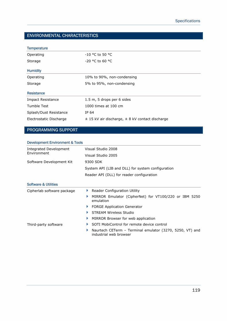
119
Specifications
ENVIRONMENTAL CHARACTERISTICS
Temperature
Operating -10 °C to 50 °C
Storage -20 °C to 60 °C
Humidity
Operating 10% to 90%, non-condensing
Storage 5% to 95%, non-condensing
Resistance
Impact Resistance 1.5 m, 5 drops per 6 sides
Tumble Test 1000 times at 100 cm
Splash/Dust Resistance IP 64
Electrostatic Discharge ± 15 kV air discharge, ± 8 kV contact discharge
PROGRAMMING SUPPORT
Development Environment & Tools
Integrated Development Environment
Visual Studio 2008
Visual Studio 2005
9300 SDK Software Development Kit
System API (LIB and DLL) for system configuration
Reader API (DLL) for reader configuration
Software & Utilities
Cipherlab software package Reader Configuration Utility
MIRROR Emulator (CipherNet) for VT100/220 or IBM 5250 emulation
FORGE Application Generator
STREAM Wireless Studio
MIRROR Browser for web application
Third-party software SOTI MobiControl for remote device control
Naurtech CETerm – Terminal emulator (3270, 5250, VT) and industrial web browser
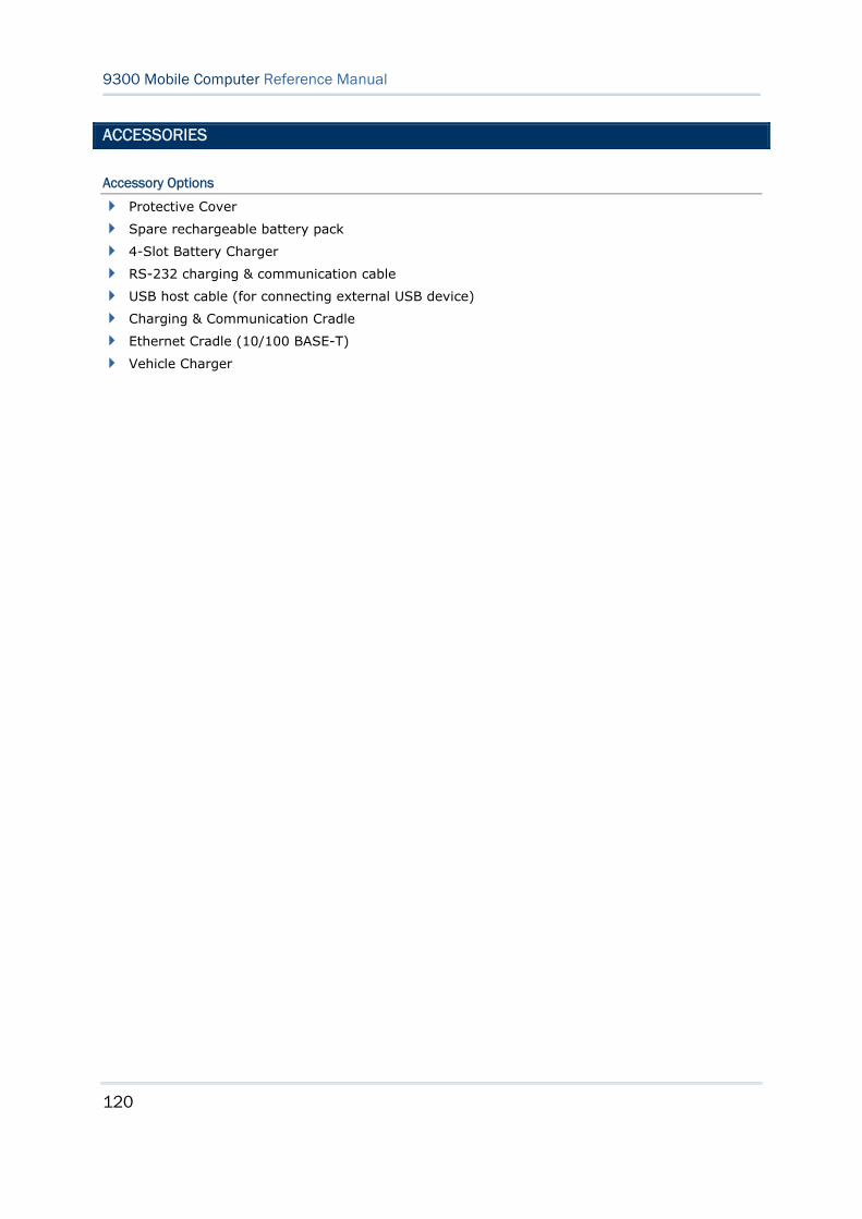
120
9300 Mobile Computer Reference Manual
ACCESSORIES
Accessory Options
Protective Cover
Spare rechargeable battery pack
4-Slot Battery Charger
RS-232 charging & communication cable
USB host cable (for connecting external USB device)
Charging & Communication Cradle
Ethernet Cradle (10/100 BASE-T)
Vehicle Charger
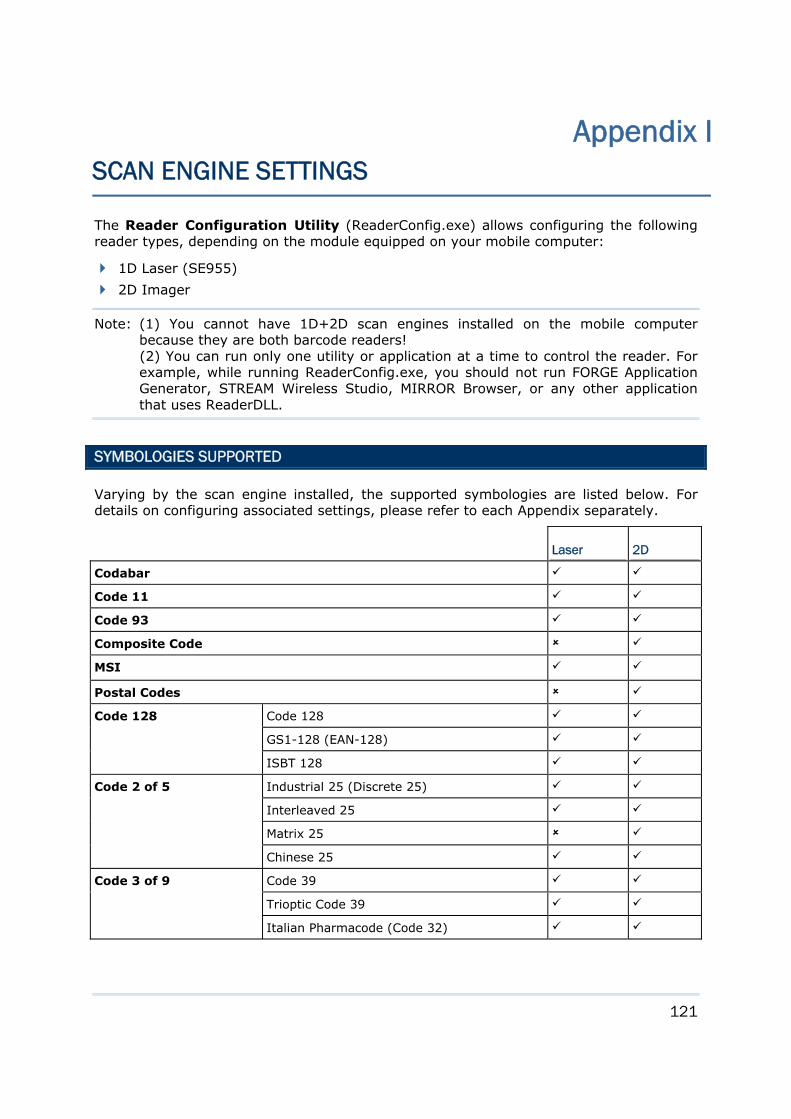
121
The Reader Configuration Utility (ReaderConfig.exe) allows configuring the following reader types, depending on the module equipped on your mobile computer:
1D Laser (SE955)
2D Imager
Note: (1) You cannot have 1D+2D scan engines installed on the mobile computer because they are both barcode readers! (2) You can run only one utility or application at a time to control the reader. For example, while running ReaderConfig.exe, you should not run FORGE Application Generator, STREAM Wireless Studio, MIRROR Browser, or any other application that uses ReaderDLL.
SYMBOLOGIES SUPPORTED
Varying by the scan engine installed, the supported symbologies are listed below. For details on configuring associated settings, please refer to each Appendix separately.
Laser 2D
Codabar
Code 11
Code 93
Composite Code
MSI
Postal Codes
Code 128 Code 128
GS1-128 (EAN-128)
ISBT 128
Code 2 of 5 Industrial 25 (Discrete 25)
Interleaved 25
Matrix 25
Chinese 25
Code 3 of 9 Code 39
Trioptic Code 39
Italian Pharmacode (Code 32)
Appendix I SCAN ENGINE SETTINGS
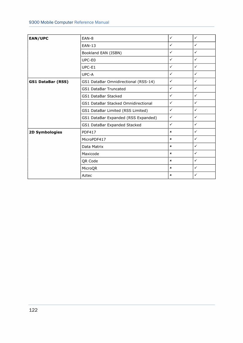
122
9300 Mobile Computer Reference Manual
EAN/UPC EAN-8
EAN-13
Bookland EAN (ISBN)
UPC-E0
UPC-E1
UPC-A
GS1 DataBar (RSS) GS1 DataBar Omnidirectional (RSS-14)
GS1 DataBar Truncated
GS1 DataBar Stacked
GS1 DataBar Stacked Omnidirectional
GS1 DataBar Limited (RSS Limited)
GS1 DataBar Expanded (RSS Expanded)
GS1 DataBar Expanded Stacked
2D Symbologies PDF417
MicroPDF417
Data Matrix
Maxicode
QR Code
MicroQR
Aztec
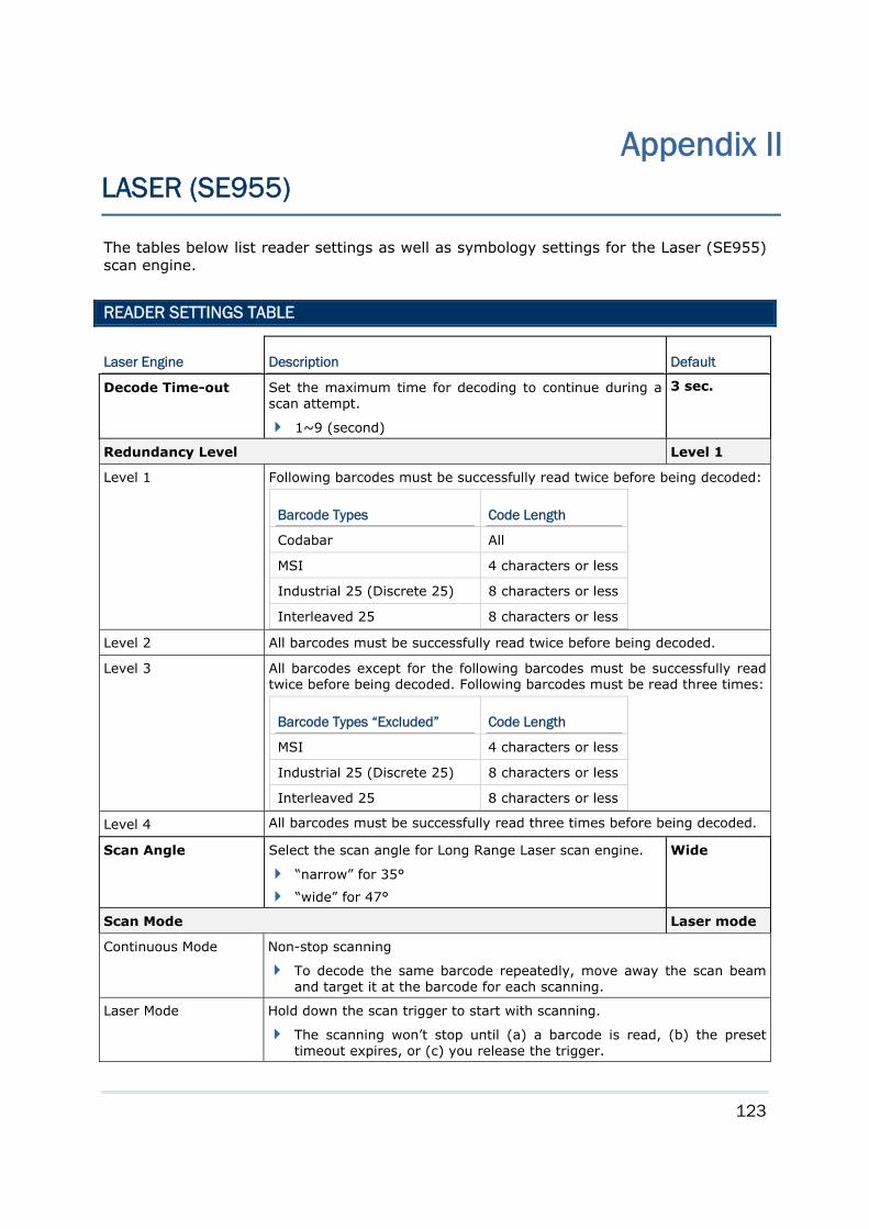
123
The tables below list reader settings as well as symbology settings for the Laser (SE955) scan engine.
READER SETTINGS TABLE
Laser Engine Description Default
Decode Time-out Set the maximum time for decoding to continue during a scan attempt.
1~9 (second)
3 sec.
Redundancy Level Level 1
Level 1 Following barcodes must be successfully read twice before being decoded:
Barcode Types Code Length
Codabar All
MSI 4 characters or less
Industrial 25 (Discrete 25) 8 characters or less
Interleaved 25 8 characters or less Level 2 All barcodes must be successfully read twice before being decoded.
Level 3 All barcodes except for the following barcodes must be successfully read twice before being decoded. Following barcodes must be read three times:
Barcode Types “Excluded” Code Length
MSI 4 characters or less
Industrial 25 (Discrete 25) 8 characters or less
Interleaved 25 8 characters or less Level 4 All barcodes must be successfully read three times before being decoded.
Scan Angle Select the scan angle for Long Range Laser scan engine.
“narrow” for 35°
“wide” for 47°
Wide
Scan Mode Laser mode
Continuous Mode Non-stop scanning
To decode the same barcode repeatedly, move away the scan beam and target it at the barcode for each scanning.
Laser Mode Hold down the scan trigger to start with scanning.
The scanning won’t stop until (a) a barcode is read, (b) the preset timeout expires, or (c) you release the trigger.
Appendix II LASER (SE955)
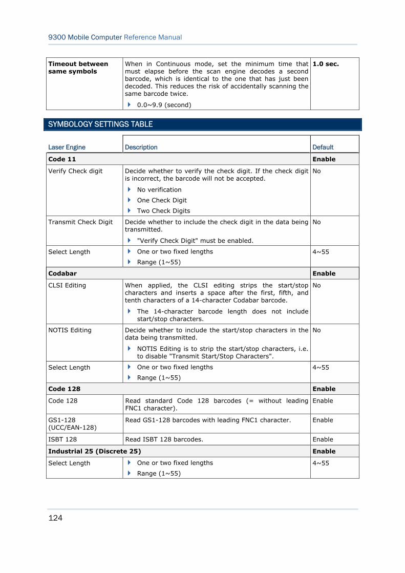
124
9300 Mobile Computer Reference Manual
Timeout between same symbols
When in Continuous mode, set the minimum time that must elapse before the scan engine decodes a second barcode, which is identical to the one that has just been decoded. This reduces the risk of accidentally scanning the same barcode twice.
0.0~9.9 (second)
1.0 sec.
SYMBOLOGY SETTINGS TABLE
Laser Engine Description Default
Code 11 Enable
Verify Check digit Decide whether to verify the check digit. If the check digit is incorrect, the barcode will not be accepted.
No verification
One Check Digit
Two Check Digits
No
Transmit Check Digit Decide whether to include the check digit in the data being transmitted.
"Verify Check Digit" must be enabled.
No
Select Length One or two fixed lengths
Range (1~55)
4~55
Codabar Enable
CLSI Editing When applied, the CLSI editing strips the start/stop characters and inserts a space after the first, fifth, and tenth characters of a 14-character Codabar barcode.
The 14-character barcode length does not include start/stop characters.
No
NOTIS Editing Decide whether to include the start/stop characters in the data being transmitted.
NOTIS Editing is to strip the start/stop characters, i.e. to disable "Transmit Start/Stop Characters".
No
Select Length One or two fixed lengths
Range (1~55)
4~55
Code 128 Enable
Code 128 Read standard Code 128 barcodes (= without leading FNC1 character).
Enable
GS1-128 (UCC/EAN-128)
Read GS1-128 barcodes with leading FNC1 character. Enable
ISBT 128 Read ISBT 128 barcodes. Enable
Industrial 25 (Discrete 25) Enable
Select Length One or two fixed lengths
Range (1~55)
4~55
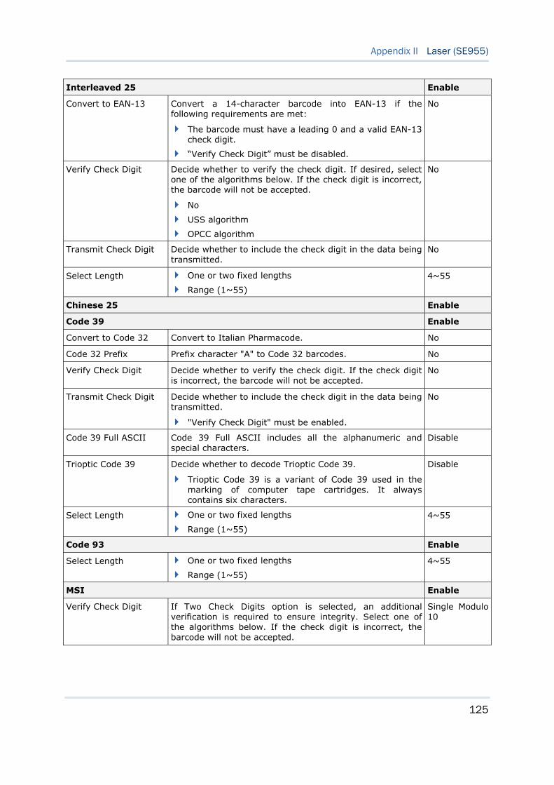
125
Appendix II Laser (SE955)
Interleaved 25 Enable
Convert to EAN-13 Convert a 14-character barcode into EAN-13 if the following requirements are met:
The barcode must have a leading 0 and a valid EAN-13 check digit.
“Verify Check Digit” must be disabled.
No
Verify Check Digit Decide whether to verify the check digit. If desired, select one of the algorithms below. If the check digit is incorrect, the barcode will not be accepted.
No
USS algorithm
OPCC algorithm
No
Transmit Check Digit Decide whether to include the check digit in the data being transmitted.
No
Select Length One or two fixed lengths
Range (1~55)
4~55
Chinese 25 Enable
Code 39 Enable
Convert to Code 32 Convert to Italian Pharmacode. No
Code 32 Prefix Prefix character "A" to Code 32 barcodes. No
Verify Check Digit Decide whether to verify the check digit. If the check digit is incorrect, the barcode will not be accepted.
No
Transmit Check Digit Decide whether to include the check digit in the data being transmitted.
"Verify Check Digit" must be enabled.
No
Code 39 Full ASCII Code 39 Full ASCII includes all the alphanumeric and special characters.
Disable
Trioptic Code 39 Decide whether to decode Trioptic Code 39.
Trioptic Code 39 is a variant of Code 39 used in the marking of computer tape cartridges. It always contains six characters.
Disable
Select Length One or two fixed lengths
Range (1~55)
4~55
Code 93 Enable
Select Length One or two fixed lengths
Range (1~55)
4~55
MSI Enable
Verify Check Digit If Two Check Digits option is selected, an additional verification is required to ensure integrity. Select one of the algorithms below. If the check digit is incorrect, the barcode will not be accepted.
Single Modulo 10
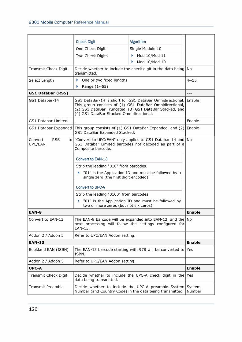
126
9300 Mobile Computer Reference Manual
Check Digit Algorithm
One Check Digit Single Modulo 10
Two Check Digits Mod 10/Mod 11
Mod 10/Mod 10
Transmit Check Digit Decide whether to include the check digit in the data being transmitted.
No
Select Length One or two fixed lengths
Range (1~55)
4~55
GS1 DataBar (RSS) ---
GS1 Databar-14 GS1 DataBar-14 is short for GS1 DataBar Omnidirectional. This group consists of (1) GS1 DataBar Omnidirectional, (2) GS1 DataBar Truncated, (3) GS1 DataBar Stacked, and (4) GS1 DataBar Stacked Omnidirectional.
Enable
GS1 Databar Limited Enable
GS1 Databar Expanded This group consists of (1) GS1 DataBar Expanded, and (2) GS1 DataBar Expanded Stacked.
Enable
Convert RSS to UPC/EAN
"Convert to UPC/EAN" only applies to GS1 Databar-14 and GS1 Databar Limited barcodes not decoded as part of a Composite barcode.
Convert to EAN-13
Strip the leading "010" from barcodes.
"01" is the Application ID and must be followed by a single zero (the first digit encoded)
Convert to UPC-A
Strip the leading "0100" from barcodes.
"01" is the Application ID and must be followed by two or more zeros (but not six zeros)
No
EAN-8 Enable
Convert to EAN-13 The EAN-8 barcode will be expanded into EAN-13, and the next processing will follow the settings configured for EAN-13.
No
Addon 2 / Addon 5 Refer to UPC/EAN Addon setting.
EAN-13 Enable
Bookland EAN (ISBN) The EAN-13 barcode starting with 978 will be converted to ISBN.
Yes
Addon 2 / Addon 5 Refer to UPC/EAN Addon setting.
UPC-A Enable
Transmit Check Digit Decide whether to include the UPC-A check digit in the data being transmitted.
Yes
Transmit Preamble Decide whether to include the UPC-A preamble System Number (and Country Code) in the data being transmitted.
System Number
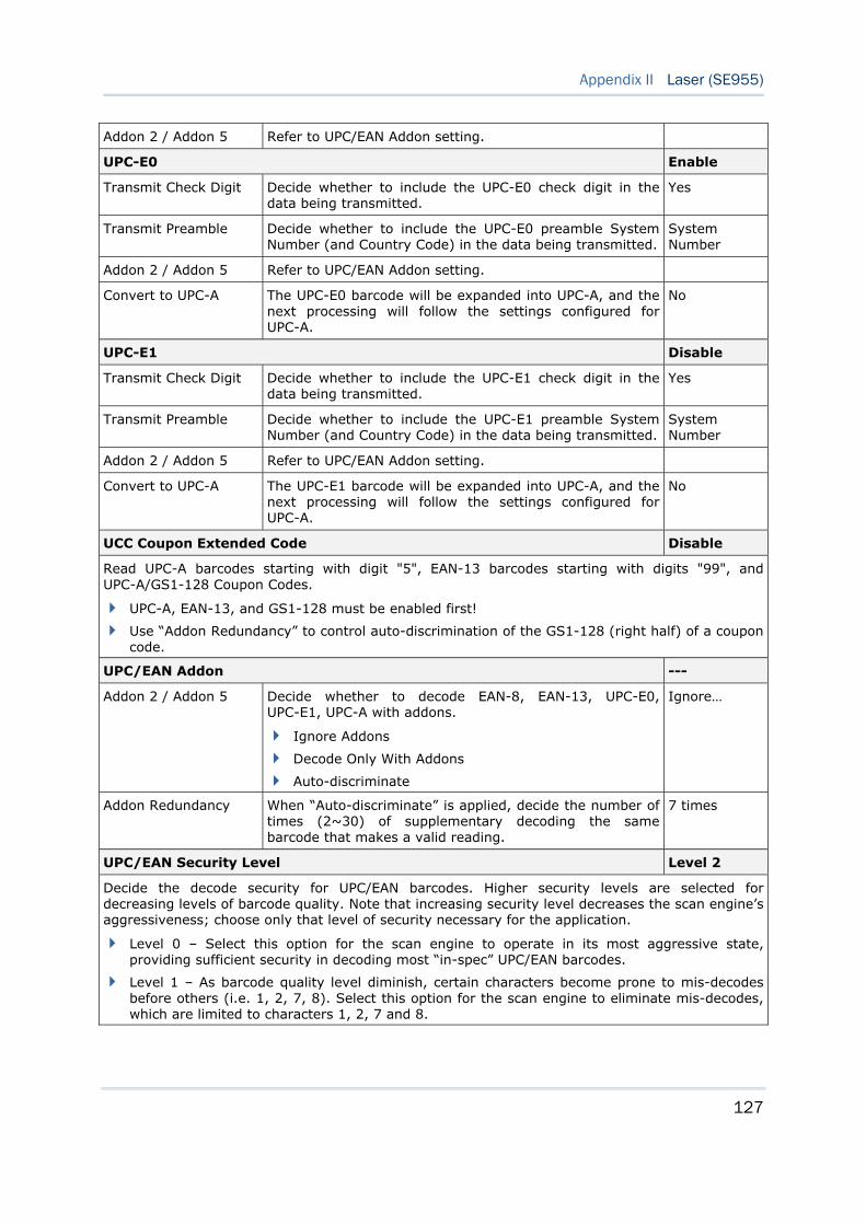
127
Appendix II Laser (SE955)
Addon 2 / Addon 5 Refer to UPC/EAN Addon setting.
UPC-E0 Enable
Transmit Check Digit Decide whether to include the UPC-E0 check digit in the data being transmitted.
Yes
Transmit Preamble Decide whether to include the UPC-E0 preamble System Number (and Country Code) in the data being transmitted.
System Number
Addon 2 / Addon 5 Refer to UPC/EAN Addon setting.
Convert to UPC-A The UPC-E0 barcode will be expanded into UPC-A, and the next processing will follow the settings configured for UPC-A.
No
UPC-E1 Disable
Transmit Check Digit Decide whether to include the UPC-E1 check digit in the data being transmitted.
Yes
Transmit Preamble Decide whether to include the UPC-E1 preamble System Number (and Country Code) in the data being transmitted.
System Number
Addon 2 / Addon 5 Refer to UPC/EAN Addon setting.
Convert to UPC-A The UPC-E1 barcode will be expanded into UPC-A, and the next processing will follow the settings configured for UPC-A.
No
UCC Coupon Extended Code Disable
Read UPC-A barcodes starting with digit "5", EAN-13 barcodes starting with digits "99", and UPC-A/GS1-128 Coupon Codes.
UPC-A, EAN-13, and GS1-128 must be enabled first!
Use “Addon Redundancy” to control auto-discrimination of the GS1-128 (right half) of a coupon code.
UPC/EAN Addon ---
Addon 2 / Addon 5 Decide whether to decode EAN-8, EAN-13, UPC-E0, UPC-E1, UPC-A with addons.
Ignore Addons
Decode Only With Addons
Auto-discriminate
Ignore…
Addon Redundancy When “Auto-discriminate” is applied, decide the number of times (2~30) of supplementary decoding the same barcode that makes a valid reading.
7 times
UPC/EAN Security Level Level 2
Decide the decode security for UPC/EAN barcodes. Higher security levels are selected for decreasing levels of barcode quality. Note that increasing security level decreases the scan engine’s aggressiveness; choose only that level of security necessary for the application.
Level 0 – Select this option for the scan engine to operate in its most aggressive state, providing sufficient security in decoding most “in-spec” UPC/EAN barcodes.
Level 1 – As barcode quality level diminish, certain characters become prone to mis-decodes before others (i.e. 1, 2, 7, 8). Select this option for the scan engine to eliminate mis-decodes, which are limited to characters 1, 2, 7 and 8.
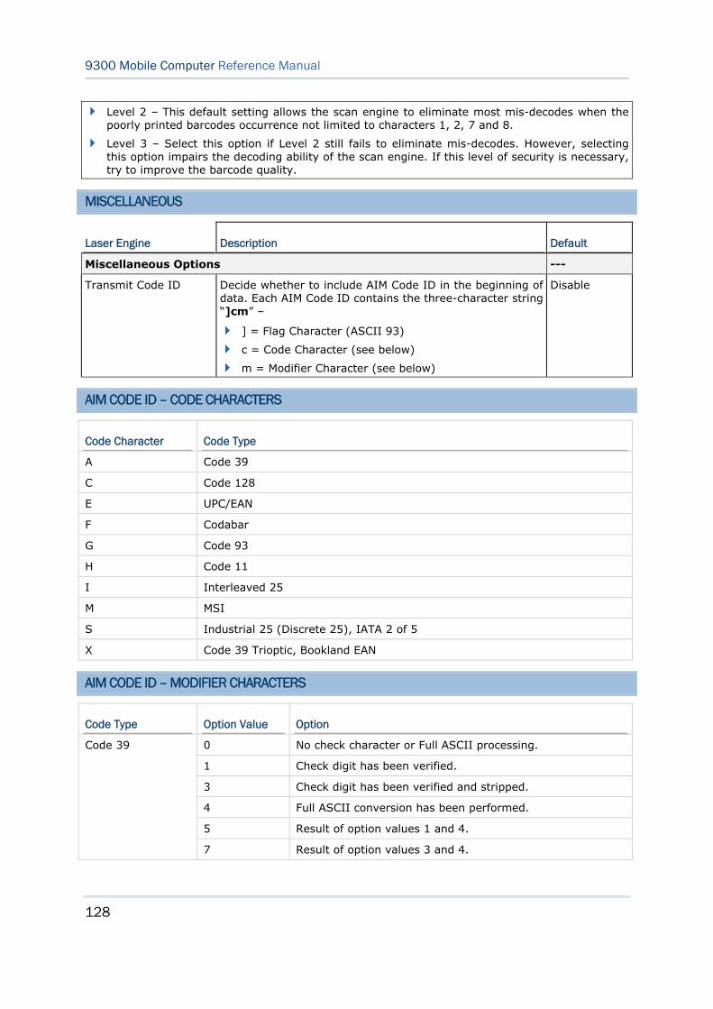
128
9300 Mobile Computer Reference Manual
Level 2 – This default setting allows the scan engine to eliminate most mis-decodes when the poorly printed barcodes occurrence not limited to characters 1, 2, 7 and 8.
Level 3 – Select this option if Level 2 still fails to eliminate mis-decodes. However, selecting this option impairs the decoding ability of the scan engine. If this level of security is necessary, try to improve the barcode quality.
MISCELLANEOUS
Laser Engine Description Default
Miscellaneous Options ---
Transmit Code ID Decide whether to include AIM Code ID in the beginning of data. Each AIM Code ID contains the three-character string “]cm” –
] = Flag Character (ASCII 93)
c = Code Character (see below)
m = Modifier Character (see below)
Disable
AIM CODE ID – CODE CHARACTERS
Code Character Code Type
A Code 39
C Code 128
E UPC/EAN
F Codabar
G Code 93
H Code 11
I Interleaved 25
M MSI
S Industrial 25 (Discrete 25), IATA 2 of 5
X Code 39 Trioptic, Bookland EAN
AIM CODE ID – MODIFIER CHARACTERS
Code Type Option Value Option
0 No check character or Full ASCII processing.
1 Check digit has been verified.
3 Check digit has been verified and stripped.
4 Full ASCII conversion has been performed.
5 Result of option values 1 and 4.
Code 39
7 Result of option values 3 and 4.
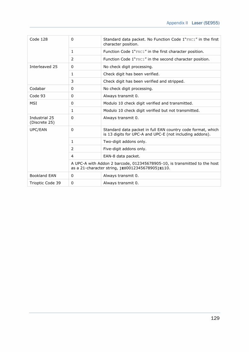
129
Appendix II Laser (SE955)
0 Standard data packet. No Function Code 1“FNC1” in the first character position.
1 Function Code 1“FNC1” in the first character position.
Code 128
2 Function Code 1“FNC1” in the second character position.
0 No check digit processing.
1 Check digit has been verified.
Interleaved 25
3 Check digit has been verified and stripped.
Codabar 0 No check digit processing.
Code 93 0 Always transmit 0.
0 Modulo 10 check digit verified and transmitted. MSI
1 Modulo 10 check digit verified but not transmitted.
Industrial 25 (Discrete 25)
0 Always transmit 0.
0 Standard data packet in full EAN country code format, which is 13 digits for UPC-A and UPC-E (not including addons).
1 Two-digit addons only.
2 Five-digit addons only.
4 EAN-8 data packet.
UPC/EAN
A UPC-A with Addon 2 barcode, 012345678905-10, is transmitted to the host as a 21-character string, ]E00012345678905]E110.
Bookland EAN 0 Always transmit 0.
Trioptic Code 39 0 Always transmit 0.

130
9300 Mobile Computer Reference Manual
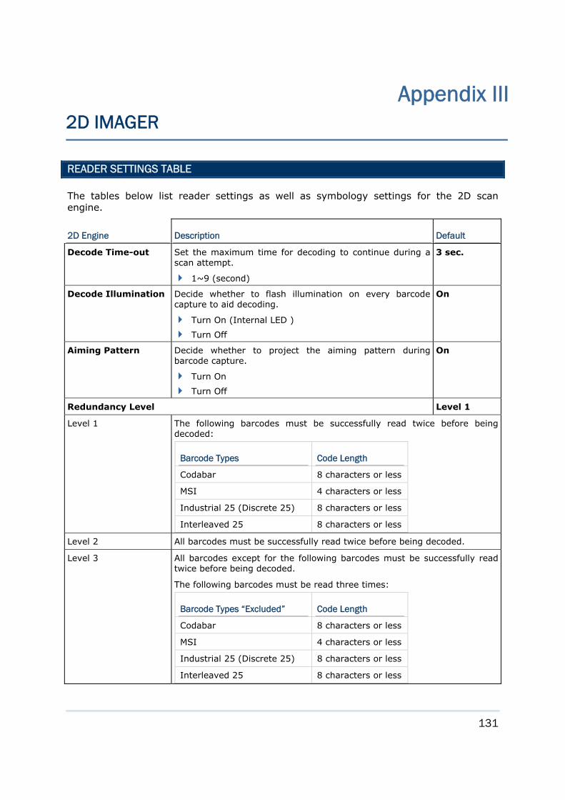
131
READER SETTINGS TABLE
The tables below list reader settings as well as symbology settings for the 2D scan engine.
2D Engine Description Default
Decode Time-out Set the maximum time for decoding to continue during a scan attempt.
1~9 (second)
3 sec.
Decode Illumination Decide whether to flash illumination on every barcode capture to aid decoding.
Turn On (Internal LED )
Turn Off
On
Aiming Pattern Decide whether to project the aiming pattern during barcode capture.
Turn On
Turn Off
On
Redundancy Level Level 1
Level 1 The following barcodes must be successfully read twice before being decoded:
Barcode Types Code Length
Codabar 8 characters or less
MSI 4 characters or less
Industrial 25 (Discrete 25) 8 characters or less
Interleaved 25 8 characters or less Level 2 All barcodes must be successfully read twice before being decoded.
Level 3 All barcodes except for the following barcodes must be successfully read twice before being decoded.
The following barcodes must be read three times:
Barcode Types “Excluded” Code Length
Codabar 8 characters or less
MSI 4 characters or less
Industrial 25 (Discrete 25) 8 characters or less
Interleaved 25 8 characters or less
Appendix III 2D IMAGER
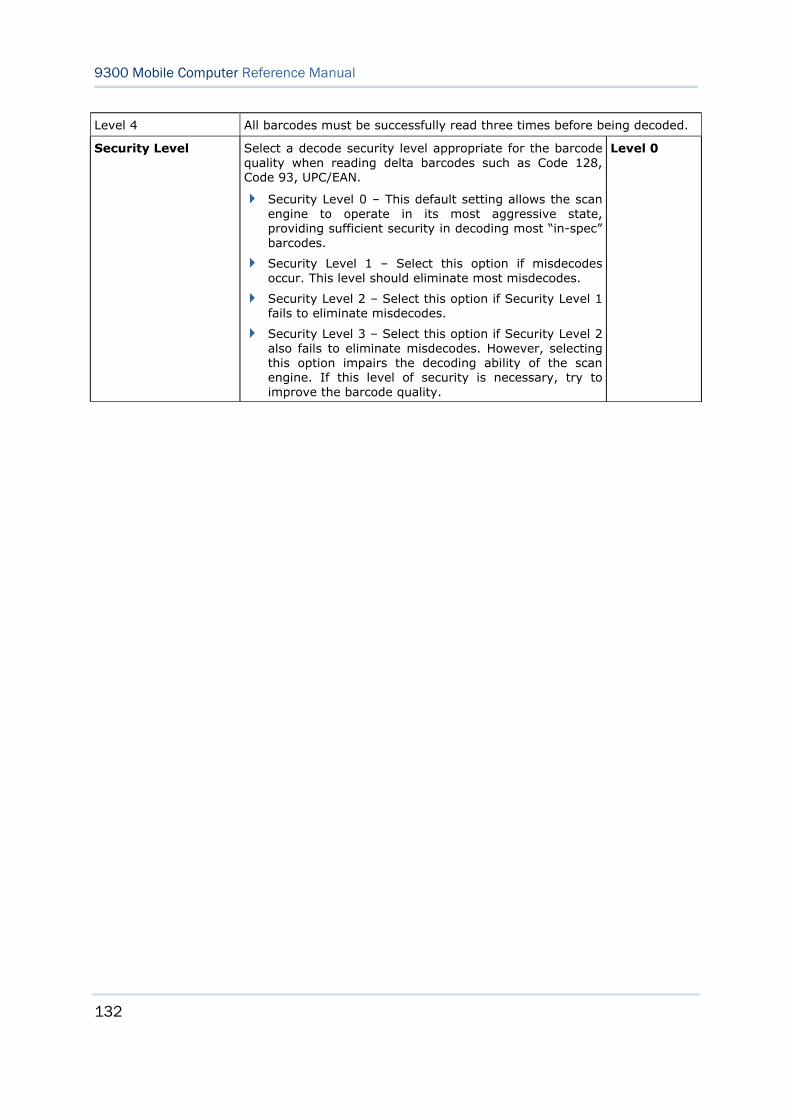
132
9300 Mobile Computer Reference Manual
Level 4 All barcodes must be successfully read three times before being decoded.
Security Level Select a decode security level appropriate for the barcode quality when reading delta barcodes such as Code 128, Code 93, UPC/EAN.
Security Level 0 – This default setting allows the scan engine to operate in its most aggressive state, providing sufficient security in decoding most “in-spec” barcodes.
Security Level 1 – Select this option if misdecodes occur. This level should eliminate most misdecodes.
Security Level 2 – Select this option if Security Level 1 fails to eliminate misdecodes.
Security Level 3 – Select this option if Security Level 2 also fails to eliminate misdecodes. However, selecting this option impairs the decoding ability of the scan engine. If this level of security is necessary, try to improve the barcode quality.
Level 0
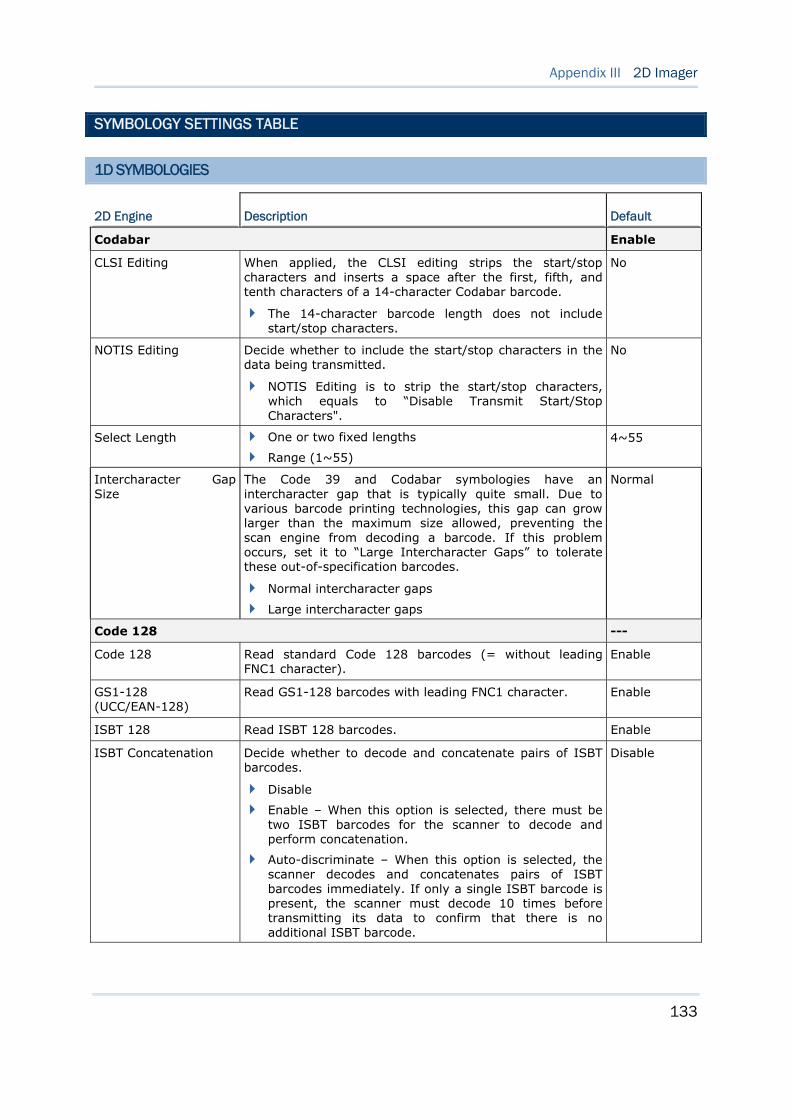
133
Appendix III 2D Imager
SYMBOLOGY SETTINGS TABLE
1D SYMBOLOGIES
2D Engine Description Default
Codabar Enable
CLSI Editing When applied, the CLSI editing strips the start/stop characters and inserts a space after the first, fifth, and tenth characters of a 14-character Codabar barcode.
The 14-character barcode length does not include start/stop characters.
No
NOTIS Editing Decide whether to include the start/stop characters in the data being transmitted.
NOTIS Editing is to strip the start/stop characters, which equals to “Disable Transmit Start/Stop Characters".
No
Select Length One or two fixed lengths
Range (1~55)
4~55
Intercharacter Gap Size
The Code 39 and Codabar symbologies have an intercharacter gap that is typically quite small. Due to various barcode printing technologies, this gap can grow larger than the maximum size allowed, preventing the scan engine from decoding a barcode. If this problem occurs, set it to “Large Intercharacter Gaps” to tolerate these out-of-specification barcodes.
Normal intercharacter gaps
Large intercharacter gaps
Normal
Code 128 ---
Code 128 Read standard Code 128 barcodes (= without leading FNC1 character).
Enable
GS1-128 (UCC/EAN-128)
Read GS1-128 barcodes with leading FNC1 character. Enable
ISBT 128 Read ISBT 128 barcodes. Enable
ISBT Concatenation Decide whether to decode and concatenate pairs of ISBT barcodes.
Disable
Enable – When this option is selected, there must be two ISBT barcodes for the scanner to decode and perform concatenation.
Auto-discriminate – When this option is selected, the scanner decodes and concatenates pairs of ISBT barcodes immediately. If only a single ISBT barcode is present, the scanner must decode 10 times before transmitting its data to confirm that there is no additional ISBT barcode.
Disable
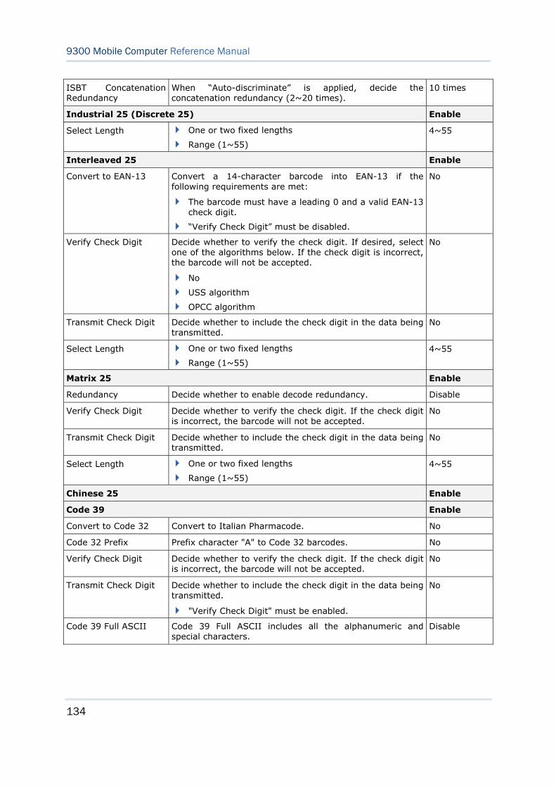
134
9300 Mobile Computer Reference Manual
ISBT Concatenation Redundancy
When “Auto-discriminate” is applied, decide the concatenation redundancy (2~20 times).
10 times
Industrial 25 (Discrete 25) Enable
Select Length One or two fixed lengths
Range (1~55)
4~55
Interleaved 25 Enable
Convert to EAN-13 Convert a 14-character barcode into EAN-13 if the following requirements are met:
The barcode must have a leading 0 and a valid EAN-13 check digit.
“Verify Check Digit” must be disabled.
No
Verify Check Digit Decide whether to verify the check digit. If desired, select one of the algorithms below. If the check digit is incorrect, the barcode will not be accepted.
No
USS algorithm
OPCC algorithm
No
Transmit Check Digit Decide whether to include the check digit in the data being transmitted.
No
Select Length One or two fixed lengths
Range (1~55)
4~55
Matrix 25 Enable
Redundancy Decide whether to enable decode redundancy. Disable
Verify Check Digit Decide whether to verify the check digit. If the check digit is incorrect, the barcode will not be accepted.
No
Transmit Check Digit Decide whether to include the check digit in the data being transmitted.
No
Select Length One or two fixed lengths
Range (1~55)
4~55
Chinese 25 Enable
Code 39 Enable
Convert to Code 32 Convert to Italian Pharmacode. No
Code 32 Prefix Prefix character "A" to Code 32 barcodes. No
Verify Check Digit Decide whether to verify the check digit. If the check digit is incorrect, the barcode will not be accepted.
No
Transmit Check Digit Decide whether to include the check digit in the data being transmitted.
"Verify Check Digit" must be enabled.
No
Code 39 Full ASCII Code 39 Full ASCII includes all the alphanumeric and special characters.
Disable
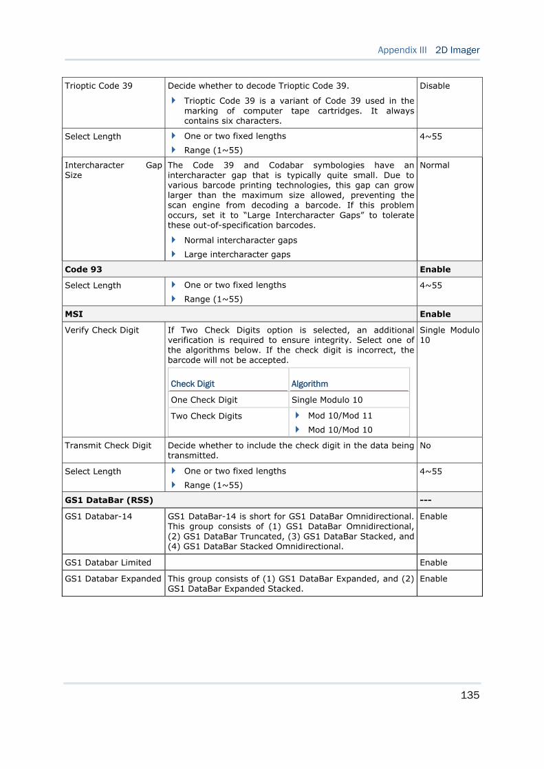
135
Appendix III 2D Imager
Trioptic Code 39 Decide whether to decode Trioptic Code 39.
Trioptic Code 39 is a variant of Code 39 used in the marking of computer tape cartridges. It always contains six characters.
Disable
Select Length One or two fixed lengths
Range (1~55)
4~55
Intercharacter Gap Size
The Code 39 and Codabar symbologies have an intercharacter gap that is typically quite small. Due to various barcode printing technologies, this gap can grow larger than the maximum size allowed, preventing the scan engine from decoding a barcode. If this problem occurs, set it to “Large Intercharacter Gaps” to tolerate these out-of-specification barcodes.
Normal intercharacter gaps
Large intercharacter gaps
Normal
Code 93 Enable
Select Length One or two fixed lengths
Range (1~55)
4~55
MSI Enable
Verify Check Digit If Two Check Digits option is selected, an additional verification is required to ensure integrity. Select one of the algorithms below. If the check digit is incorrect, the barcode will not be accepted.
Check Digit Algorithm
One Check Digit Single Modulo 10
Two Check Digits Mod 10/Mod 11
Mod 10/Mod 10
Single Modulo 10
Transmit Check Digit Decide whether to include the check digit in the data being transmitted.
No
Select Length One or two fixed lengths
Range (1~55)
4~55
GS1 DataBar (RSS) ---
GS1 Databar-14 GS1 DataBar-14 is short for GS1 DataBar Omnidirectional. This group consists of (1) GS1 DataBar Omnidirectional, (2) GS1 DataBar Truncated, (3) GS1 DataBar Stacked, and (4) GS1 DataBar Stacked Omnidirectional.
Enable
GS1 Databar Limited Enable
GS1 Databar Expanded This group consists of (1) GS1 DataBar Expanded, and (2) GS1 DataBar Expanded Stacked.
Enable
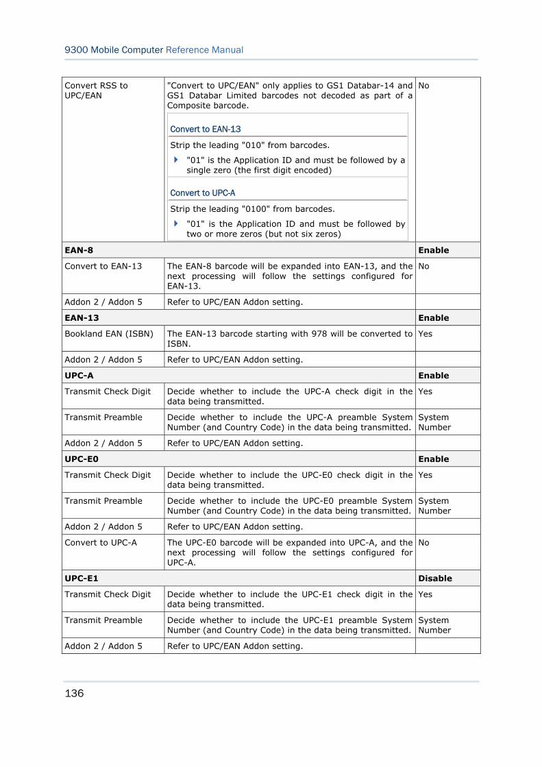
136
9300 Mobile Computer Reference Manual
Convert RSS to UPC/EAN
"Convert to UPC/EAN" only applies to GS1 Databar-14 and GS1 Databar Limited barcodes not decoded as part of a Composite barcode.
Convert to EAN-13
Strip the leading "010" from barcodes.
"01" is the Application ID and must be followed by a single zero (the first digit encoded)
Convert to UPC-A
Strip the leading "0100" from barcodes.
"01" is the Application ID and must be followed by two or more zeros (but not six zeros)
No
EAN-8 Enable
Convert to EAN-13 The EAN-8 barcode will be expanded into EAN-13, and the next processing will follow the settings configured for EAN-13.
No
Addon 2 / Addon 5 Refer to UPC/EAN Addon setting.
EAN-13 Enable
Bookland EAN (ISBN) The EAN-13 barcode starting with 978 will be converted to ISBN.
Yes
Addon 2 / Addon 5 Refer to UPC/EAN Addon setting.
UPC-A Enable
Transmit Check Digit Decide whether to include the UPC-A check digit in the data being transmitted.
Yes
Transmit Preamble Decide whether to include the UPC-A preamble System Number (and Country Code) in the data being transmitted.
System Number
Addon 2 / Addon 5 Refer to UPC/EAN Addon setting.
UPC-E0 Enable
Transmit Check Digit Decide whether to include the UPC-E0 check digit in the data being transmitted.
Yes
Transmit Preamble Decide whether to include the UPC-E0 preamble System Number (and Country Code) in the data being transmitted.
System Number
Addon 2 / Addon 5 Refer to UPC/EAN Addon setting.
Convert to UPC-A The UPC-E0 barcode will be expanded into UPC-A, and the next processing will follow the settings configured for UPC-A.
No
UPC-E1 Disable
Transmit Check Digit Decide whether to include the UPC-E1 check digit in the data being transmitted.
Yes
Transmit Preamble Decide whether to include the UPC-E1 preamble System Number (and Country Code) in the data being transmitted.
System Number
Addon 2 / Addon 5 Refer to UPC/EAN Addon setting.
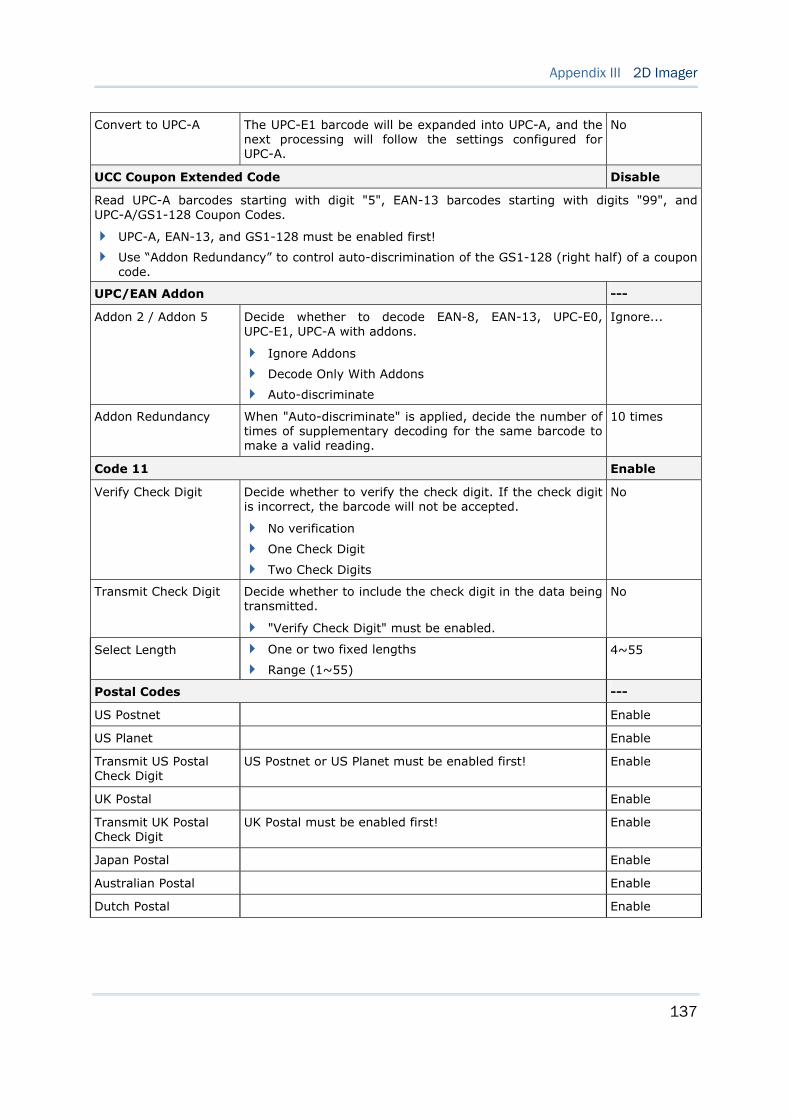
137
Appendix III 2D Imager
Convert to UPC-A The UPC-E1 barcode will be expanded into UPC-A, and the next processing will follow the settings configured for UPC-A.
No
UCC Coupon Extended Code Disable
Read UPC-A barcodes starting with digit "5", EAN-13 barcodes starting with digits "99", and UPC-A/GS1-128 Coupon Codes.
UPC-A, EAN-13, and GS1-128 must be enabled first!
Use “Addon Redundancy” to control auto-discrimination of the GS1-128 (right half) of a coupon code.
UPC/EAN Addon ---
Addon 2 / Addon 5 Decide whether to decode EAN-8, EAN-13, UPC-E0, UPC-E1, UPC-A with addons.
Ignore Addons
Decode Only With Addons
Auto-discriminate
Ignore...
Addon Redundancy When "Auto-discriminate" is applied, decide the number of times of supplementary decoding for the same barcode to make a valid reading.
10 times
Code 11 Enable
Verify Check Digit Decide whether to verify the check digit. If the check digit is incorrect, the barcode will not be accepted.
No verification
One Check Digit
Two Check Digits
No
Transmit Check Digit Decide whether to include the check digit in the data being transmitted.
"Verify Check Digit" must be enabled.
No
Select Length One or two fixed lengths
Range (1~55)
4~55
Postal Codes ---
US Postnet Enable
US Planet Enable
Transmit US Postal Check Digit
US Postnet or US Planet must be enabled first! Enable
UK Postal Enable
Transmit UK Postal Check Digit
UK Postal must be enabled first! Enable
Japan Postal Enable
Australian Postal Enable
Dutch Postal Enable
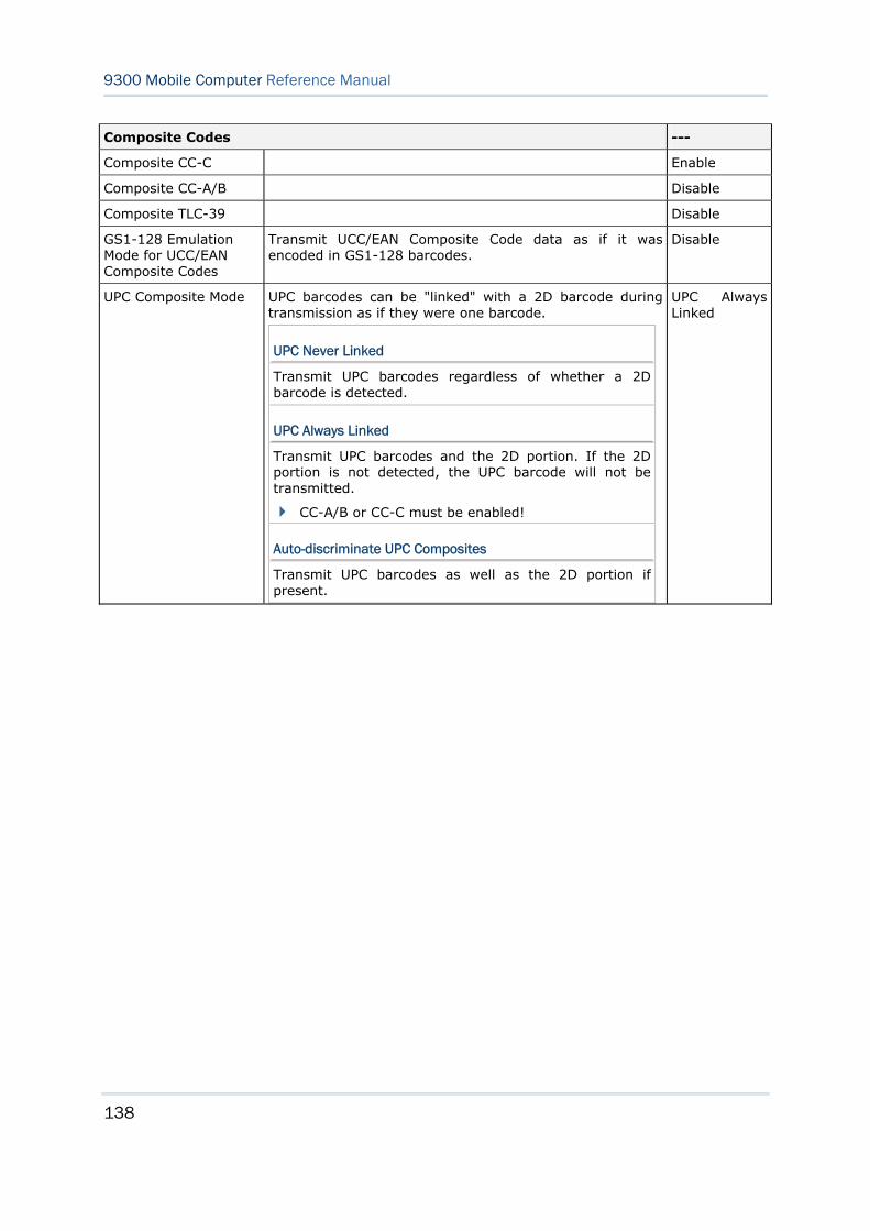
138
9300 Mobile Computer Reference Manual
Composite Codes ---
Composite CC-C Enable
Composite CC-A/B Disable
Composite TLC-39 Disable
GS1-128 Emulation Mode for UCC/EAN Composite Codes
Transmit UCC/EAN Composite Code data as if it was encoded in GS1-128 barcodes.
Disable
UPC Composite Mode UPC barcodes can be "linked" with a 2D barcode during transmission as if they were one barcode.
UPC Never Linked
Transmit UPC barcodes regardless of whether a 2D barcode is detected.
UPC Always Linked
Transmit UPC barcodes and the 2D portion. If the 2D portion is not detected, the UPC barcode will not be transmitted.
CC-A/B or CC-C must be enabled!
Auto-discriminate UPC Composites
Transmit UPC barcodes as well as the 2D portion if present.
UPC Always Linked
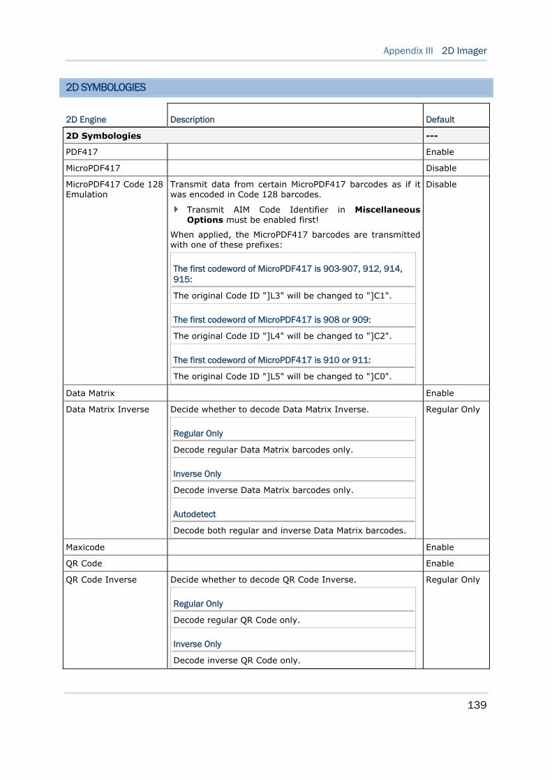
139
Appendix III 2D Imager
2D SYMBOLOGIES
2D Engine Description Default
2D Symbologies ---
PDF417 Enable
MicroPDF417 Disable
MicroPDF417 Code 128 Emulation
Transmit data from certain MicroPDF417 barcodes as if it was encoded in Code 128 barcodes.
Transmit AIM Code Identifier in Miscellaneous Options must be enabled first!
When applied, the MicroPDF417 barcodes are transmitted with one of these prefixes:
The first codeword of MicroPDF417 is 903-907, 912, 914, 915:
The original Code ID "]L3" will be changed to "]C1".
The first codeword of MicroPDF417 is 908 or 909:
The original Code ID "]L4" will be changed to "]C2".
The first codeword of MicroPDF417 is 910 or 911:
The original Code ID "]L5" will be changed to "]C0".
Disable
Data Matrix Enable
Data Matrix Inverse Decide whether to decode Data Matrix Inverse.
Regular Only
Decode regular Data Matrix barcodes only.
Inverse Only
Decode inverse Data Matrix barcodes only.
Autodetect
Decode both regular and inverse Data Matrix barcodes.
Regular Only
Maxicode Enable
QR Code Enable
QR Code Inverse Decide whether to decode QR Code Inverse.
Regular Only
Decode regular QR Code only.
Inverse Only
Decode inverse QR Code only.
Regular Only
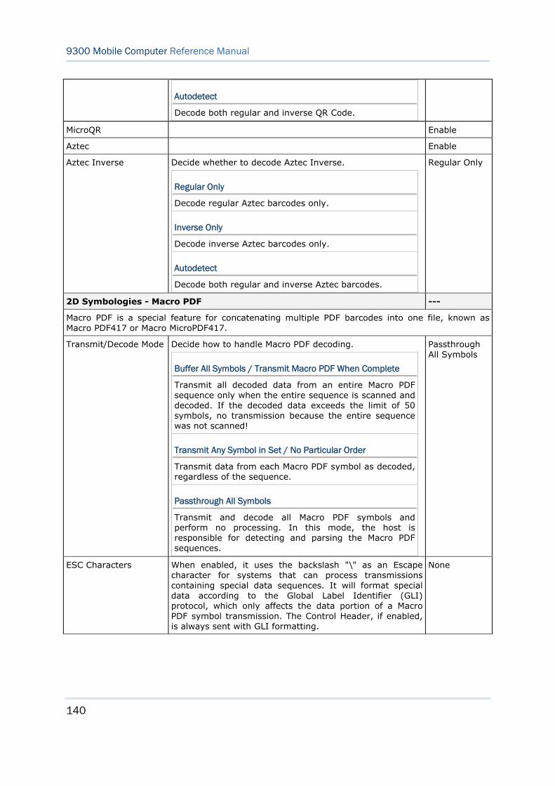
140
9300 Mobile Computer Reference Manual
Autodetect
Decode both regular and inverse QR Code.
MicroQR Enable
Aztec Enable
Aztec Inverse Decide whether to decode Aztec Inverse.
Regular Only
Decode regular Aztec barcodes only.
Inverse Only
Decode inverse Aztec barcodes only.
Autodetect
Decode both regular and inverse Aztec barcodes.
Regular Only
2D Symbologies - Macro PDF ---
Macro PDF is a special feature for concatenating multiple PDF barcodes into one file, known as Macro PDF417 or Macro MicroPDF417.
Transmit/Decode Mode Decide how to handle Macro PDF decoding.
Buffer All Symbols / Transmit Macro PDF When Complete
Transmit all decoded data from an entire Macro PDF sequence only when the entire sequence is scanned and decoded. If the decoded data exceeds the limit of 50 symbols, no transmission because the entire sequence was not scanned!
Transmit Any Symbol in Set / No Particular Order
Transmit data from each Macro PDF symbol as decoded, regardless of the sequence.
Passthrough All Symbols
Transmit and decode all Macro PDF symbols and perform no processing. In this mode, the host is responsible for detecting and parsing the Macro PDF sequences.
Passthrough All Symbols
ESC Characters When enabled, it uses the backslash "\" as an Escape character for systems that can process transmissions containing special data sequences. It will format special data according to the Global Label Identifier (GLI) protocol, which only affects the data portion of a Macro PDF symbol transmission. The Control Header, if enabled, is always sent with GLI formatting.
None
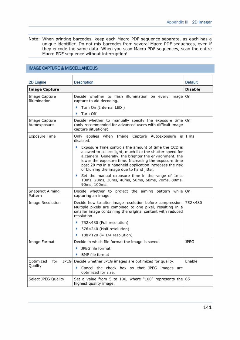
141
Appendix III 2D Imager
Note: When printing barcodes, keep each Macro PDF sequence separate, as each has a unique identifier. Do not mix barcodes from several Macro PDF sequences, even if they encode the same data. When you scan Macro PDF sequences, scan the entire Macro PDF sequence without interruption!
IMAGE CAPTURE & MISCELLANEOUS
2D Engine Description Default
Image Capture Disable
Image Capture Illumination
Decide whether to flash illumination on every image capture to aid decoding.
Turn On (Internal LED )
Turn Off
On
Image Capture Autoexposure
Decide whether to manually specify the exposure time (only recommended for advanced users with difficult image capture situations).
On
Exposure Time Only applies when Image Capture Autoexposure is disabled.
Exposure Time controls the amount of time the CCD is allowed to collect light, much like the shutter speed for a camera. Generally, the brighter the environment, the lower the exposure time. Increasing the exposure time past 20 ms in a handheld application increases the risk of blurring the image due to hand jitter.
Set the manual exposure time in the range of 1ms, 10ms, 20ms, 30ms, 40ms, 50ms, 60ms, 70ms, 80ms, 90ms, 100ms.
1 ms
Snapshot Aiming Pattern
Decide whether to project the aiming pattern while capturing an image.
On
Image Resolution Decide how to alter image resolution before compression. Multiple pixels are combined to one pixel, resulting in a smaller image containing the original content with reduced resolution.
752×480 (Full resolution)
376×240 (Half resolution)
188×120 (= 1/4 resolution)
752×480
Image Format Decide in which file format the image is saved.
JPEG file format
BMP file format
JPEG
Optimized for JPEG Quality
Decide whether JPEG images are optimized for quality.
Cancel the check box so that JPEG images are optimized for size.
Enable
Select JPEG Quality Set a value from 5 to 100, where “100” represents the highest quality image.
65
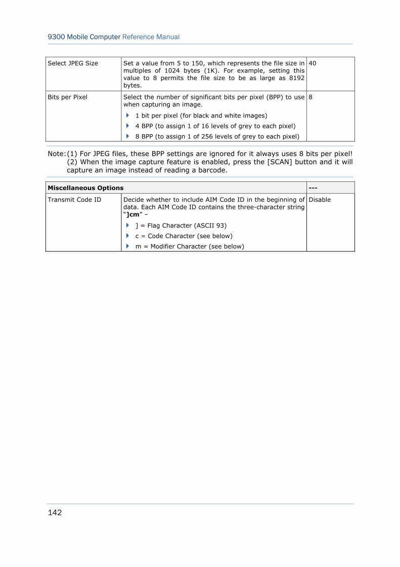
142
9300 Mobile Computer Reference Manual
Select JPEG Size Set a value from 5 to 150, which represents the file size in multiples of 1024 bytes (1K). For example, setting this value to 8 permits the file size to be as large as 8192 bytes.
40
Bits per Pixel Select the number of significant bits per pixel (BPP) to use when capturing an image.
1 bit per pixel (for black and white images)
4 BPP (to assign 1 of 16 levels of grey to each pixel)
8 BPP (to assign 1 of 256 levels of grey to each pixel)
8
Note: (1) For JPEG files, these BPP settings are ignored for it always uses 8 bits per pixel! (2) When the image capture feature is enabled, press the [SCAN] button and it will capture an image instead of reading a barcode.
Miscellaneous Options ---
Transmit Code ID Decide whether to include AIM Code ID in the beginning of data. Each AIM Code ID contains the three-character string “]cm” –
] = Flag Character (ASCII 93)
c = Code Character (see below)
m = Modifier Character (see below)
Disable
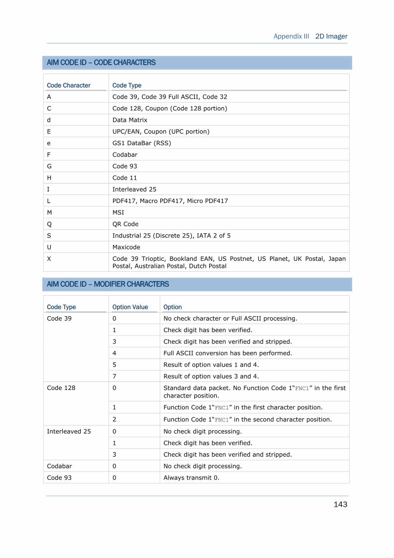
143
Appendix III 2D Imager
AIM CODE ID – CODE CHARACTERS
Code Character Code Type
A Code 39, Code 39 Full ASCII, Code 32
C Code 128, Coupon (Code 128 portion)
d Data Matrix
E UPC/EAN, Coupon (UPC portion)
e GS1 DataBar (RSS)
F Codabar
G Code 93
H Code 11
I Interleaved 25
L PDF417, Macro PDF417, Micro PDF417
M MSI
Q QR Code
S Industrial 25 (Discrete 25), IATA 2 of 5
U Maxicode
X Code 39 Trioptic, Bookland EAN, US Postnet, US Planet, UK Postal, Japan Postal, Australian Postal, Dutch Postal
AIM CODE ID – MODIFIER CHARACTERS
Code Type Option Value Option
0 No check character or Full ASCII processing.
1 Check digit has been verified.
3 Check digit has been verified and stripped.
4 Full ASCII conversion has been performed.
5 Result of option values 1 and 4.
Code 39
7 Result of option values 3 and 4.
0 Standard data packet. No Function Code 1“FNC1” in the first character position.
1 Function Code 1“FNC1” in the first character position.
Code 128
2 Function Code 1“FNC1” in the second character position.
0 No check digit processing.
1 Check digit has been verified.
Interleaved 25
3 Check digit has been verified and stripped.
Codabar 0 No check digit processing.
Code 93 0 Always transmit 0.
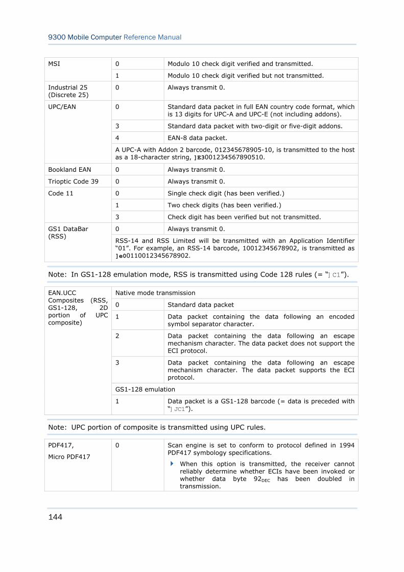
144
9300 Mobile Computer Reference Manual
0 Modulo 10 check digit verified and transmitted. MSI
1 Modulo 10 check digit verified but not transmitted.
Industrial 25 (Discrete 25)
0 Always transmit 0.
0 Standard data packet in full EAN country code format, which is 13 digits for UPC-A and UPC-E (not including addons).
3 Standard data packet with two-digit or five-digit addons.
4 EAN-8 data packet.
UPC/EAN
A UPC-A with Addon 2 barcode, 012345678905-10, is transmitted to the host as a 18-character string, ]E3001234567890510.
Bookland EAN 0 Always transmit 0.
Trioptic Code 39 0 Always transmit 0.
0 Single check digit (has been verified.)
1 Two check digits (has been verified.)
Code 11
3 Check digit has been verified but not transmitted.
0 Always transmit 0. GS1 DataBar (RSS)
RSS-14 and RSS Limited will be transmitted with an Application Identifier “01”. For example, an RSS-14 barcode, 10012345678902, is transmitted as ]e00110012345678902.
Note: In GS1-128 emulation mode, RSS is transmitted using Code 128 rules (= “]C1”).
Native mode transmission
0 Standard data packet
1 Data packet containing the data following an encoded symbol separator character.
2 Data packet containing the data following an escape mechanism character. The data packet does not support the ECI protocol.
3 Data packet containing the data following an escape mechanism character. The data packet supports the ECI protocol.
GS1-128 emulation
EAN.UCC Composites (RSS, GS1-128, 2D portion of UPC composite)
1 Data packet is a GS1-128 barcode (= data is preceded with “]JC1”).
Note: UPC portion of composite is transmitted using UPC rules.
PDF417,
Micro PDF417
0 Scan engine is set to conform to protocol defined in 1994 PDF417 symbology specifications.
When this option is transmitted, the receiver cannot reliably determine whether ECIs have been invoked or whether data byte 92DEC has been doubled in transmission.
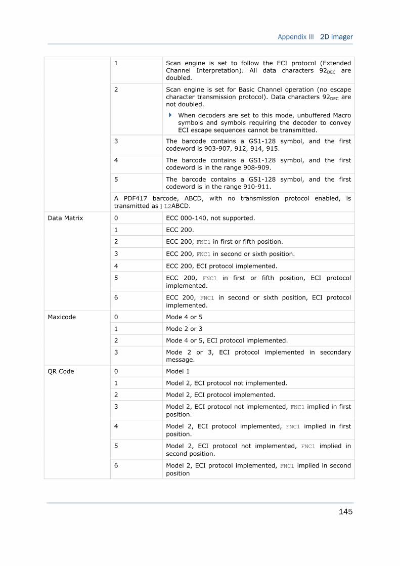
145
Appendix III 2D Imager
1 Scan engine is set to follow the ECI protocol (Extended Channel Interpretation). All data characters 92DEC are doubled.
2 Scan engine is set for Basic Channel operation (no escape character transmission protocol). Data characters 92DEC are not doubled.
When decoders are set to this mode, unbuffered Macro symbols and symbols requiring the decoder to convey ECI escape sequences cannot be transmitted.
3 The barcode contains a GS1-128 symbol, and the first codeword is 903-907, 912, 914, 915.
4 The barcode contains a GS1-128 symbol, and the first codeword is in the range 908-909.
5 The barcode contains a GS1-128 symbol, and the first codeword is in the range 910-911.
A PDF417 barcode, ABCD, with no transmission protocol enabled, is transmitted as ]L2ABCD.
0 ECC 000-140, not supported.
1 ECC 200.
2 ECC 200, FNC1 in first or fifth position.
3 ECC 200, FNC1 in second or sixth position.
4 ECC 200, ECI protocol implemented.
5 ECC 200, FNC1 in first or fifth position, ECI protocol implemented.
Data Matrix
6 ECC 200, FNC1 in second or sixth position, ECI protocol implemented.
0 Mode 4 or 5
1 Mode 2 or 3
2 Mode 4 or 5, ECI protocol implemented.
Maxicode
3 Mode 2 or 3, ECI protocol implemented in secondary message.
0 Model 1
1 Model 2, ECI protocol not implemented.
2 Model 2, ECI protocol implemented.
3 Model 2, ECI protocol not implemented, FNC1 implied in first position.
4 Model 2, ECI protocol implemented, FNC1 implied in first position.
5 Model 2, ECI protocol not implemented, FNC1 implied in second position.
QR Code
6 Model 2, ECI protocol implemented, FNC1 implied in second position

146
9300 Mobile Computer Reference Manual
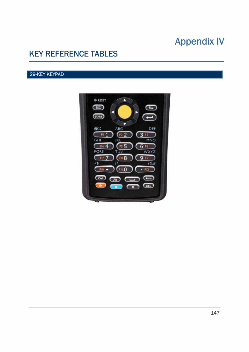
147
29-KEY KEYPAD
Appendix IV KEY REFERENCE TABLES
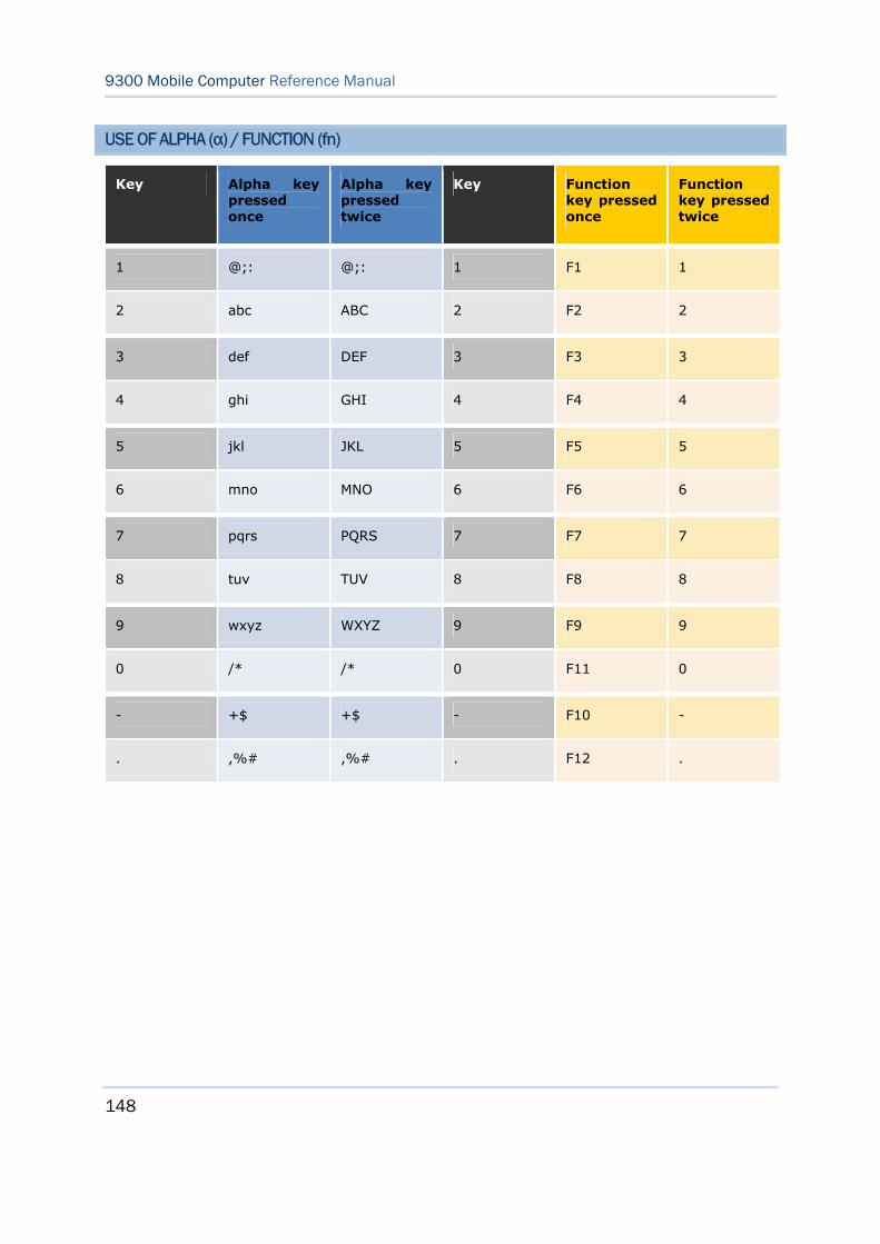
148
9300 Mobile Computer Reference Manual
USE OF ALPHA (α) / FUNCTION (fn)
Key Alpha key pressed once
Alpha key pressed twice
Key Function key pressed once
Function key pressed twice
1 @;: @;: 1 F1 1
2 abc ABC 2 F2 2
3 def DEF 3 F3 3
4 ghi GHI 4 F4 4
5 jkl JKL 5 F5 5
6 mno MNO 6 F6 6
7 pqrs PQRS 7 F7 7
8 tuv TUV 8 F8 8
9 wxyz WXYZ 9 F9 9
0 /* /* 0 F11 0
- +$ +$ - F10 -
. ,%# ,%# . F12 .
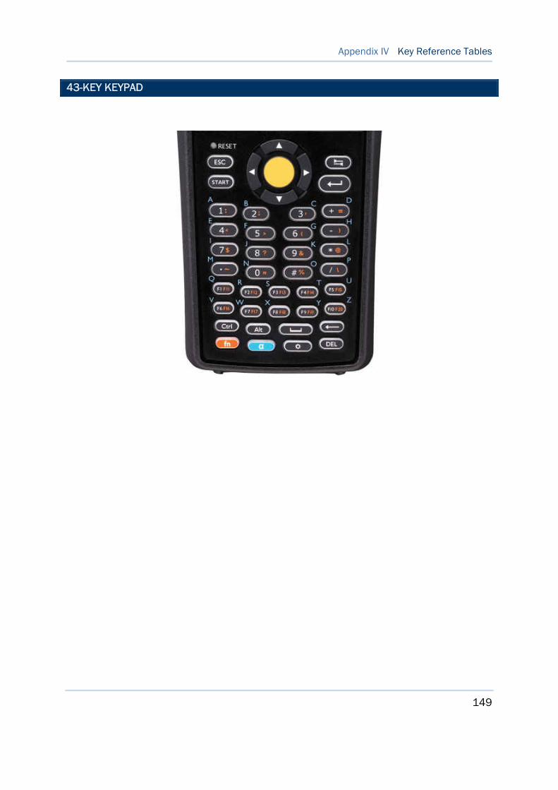
149
Appendix IV Key Reference Tables
43-KEY KEYPAD
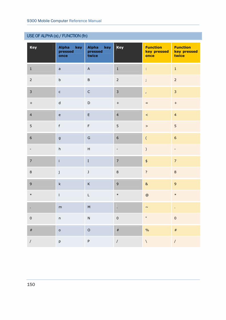
150
9300 Mobile Computer Reference Manual
USE OF ALPHA (α) / FUNCTION (fn)
Key Alpha key pressed once
Alpha key pressed twice
Key Function key pressed once
Function key pressed twice
1 a A 1 : 1
2 b B 2 ; 2
3 c C 3 , 3
+ d D + = +
4 e E 4 < 4
5 f F 5 > 5
6 g G 6 ( 6
- h H - ) -
7 i I 7 $ 7
8 j J 8 ? 8
9 k K 9 & 9
* l L * @ *
. m M . ~ .
0 n N 0 " 0
# o O # % #
/ p P / \ /
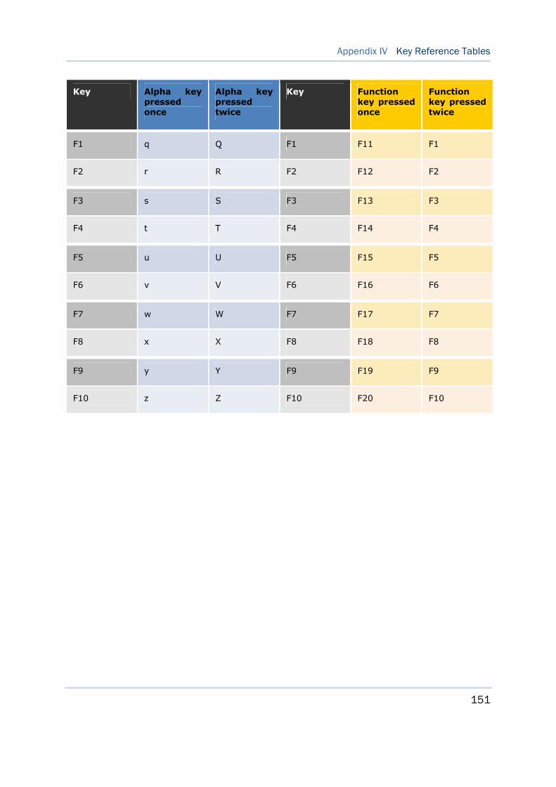
151
Appendix IV Key Reference Tables
Key Alpha key pressed once
Alpha key pressed twice
Key Function key pressed once
Function key pressed twice
F1 q Q F1 F11 F1
F2 r R F2 F12 F2
F3 s S F3 F13 F3
F4 t T F4 F14 F4
F5 u U F5 F15 F5
F6 v V F6 F16 F6
F7 w W F7 F17 F7
F8 x X F8 F18 F8
F9 y Y F9 F19 F9
F10 z Z F10 F20 F10