924 ST2 99653 - Flowmetrics
126
99653 02/07 924-ST2 Flow Computer
Transcript of 924 ST2 99653 - Flowmetrics
99653 02/07
924-ST2Flow Computer

924-ST2 Flow Computer
SAFETY INSTRUCTIONS .............................................................................................................11. INTRODUCTION 1.1 Unit Description ............................................................................................................2 1.2 Specifi cations ...............................................................................................................32. INSTALLATION 2.1 General Mounting Hints ..............................................................................................10 2.2 Mounting Diagrams ....................................................................................................103. APPLICATIONS 3.1 Steam Mass ................................................................................................................13 3.2 Steam Heat .................................................................................................................14 3.3 Steam Net Heat ..........................................................................................................15 3.4 Steam Delta Heat .......................................................................................................16 3.5 Corrected Gas Volume ...............................................................................................17 3.6 Gas Mass ...................................................................................................................18 3.7 Gas Combustion Heat ................................................................................................19 3.8 Corrected Liquid Volume ............................................................................................20 3.9 Liquid Mass ................................................................................................................21 3.10 Liquid Combustion Heat ...........................................................................................22 3.11 Liquid Sensible Heat .................................................................................................23 3.12 Liquid Delta Heat ......................................................................................................24
4. WIRING 4.1 Terminal Designations ................................................................................................25 4.2 Typical Wiring Connections ........................................................................................26 4.2.1 Flow Input ...................................................................................................26 4.2.2 Stacked DP Input ........................................................................................26 4.2.3 Pressure Input ............................................................................................26 4.2.4 Temperature Input ......................................................................................27 4.2.5 Temperature 2 Input ...................................................................................27 4.3 Wiring In Hazardous Areas .........................................................................................28 4.3.1 Flow Input ...................................................................................................28 4.3.2 Pressure Input ............................................................................................28 4.3.3 Temperature Input ......................................................................................28
5. UNIT OPERATION 5.1 Front Panel Operation Concept for Operate Mode .....................................................29 5.2 General Operation ......................................................................................................30 5.3 Password Protection ...................................................................................................30 5.4 Relay Operation ..........................................................................................................30
5.5 Pulse Output ..............................................................................................................305.6 Analog Outputs ...........................................................................................................305.7 Function Keys; Display Grouping ...............................................................................30
5.8 RS-232 Serial Port Operation .....................................................................................31 5.8.1 PC Communications ...................................................................................31 5.8.2 Operation of RS-232 Serial Port with Printers ............................................31
5.9 RS-485 Serial Port Operation .....................................................................................315.10 Pause Computations Prompt ....................................................................................31
6. PROGRAMMING 6.1 Front Panel Operation Concept for Program Mode ....................................................32 6.2 EZ Setup ....................................................................................................................33 6.3 Detailed Menu Descriptions ........................................................................................34 6.4 System Parameters ....................................................................................................36 6.5 Display ........................................................................................................................41 6.6 System Units ..............................................................................................................43 6.7 Fluid Data ...................................................................................................................50 6.8 Flow Input ...................................................................................................................55 6.9 Other Input ..................................................................................................................67 6.10 Pulse Output .............................................................................................................70 6.11 Current Output ..........................................................................................................73 6.12 Relays .......................................................................................................................75 6.13 Communication .........................................................................................................79 6.14 Network Card ............................................................................................................88 6.15 Service & Analysis ....................................................................................................89
CONTENTS
924-ST2 Flow Computer
7. PRINCIPLE OF OPERATION 7.1 General .......................................................................................................................95 7.2 Square Law Flowmeter Considerations ......................................................................95 7.3 Flow Equations ...........................................................................................................95 7.3.1 Flow Input Computation ..............................................................................95 7.3.2 Pressure Computation ................................................................................96 7.3.3 Temperature Computation ..........................................................................96 7.3.4 Density/Viscosity Computation ...................................................................96 7.3.5 Corrected Volume Flow Computation .........................................................97 7.3.6 Mass Flow Computation .............................................................................98 7.3.7 Combustion Heat Flow Computation ..........................................................98 7.3.8 Heat Flow Computation ..............................................................................99 7.3.9 Sensible Heat Flow Computation ...............................................................99 7.3.10 Liquid Delta Heat Computation .................................................................99 7.3.11 Expansion Factor Computation for Square Law Flowmeters ...................99 7.3.12 Uncompensated Flow Computation .......................................................100 7.3.13 ILVA Flow Meter Equations ....................................................................101 7.4 Computation of the D.P. Factor ................................................................................102
8. RS-232 SERIAL PORT 8.1 RS-232 Serial Port Description .................................................................................103 8.2 Instrument Setup by PC Over Serial Port ................................................................103 8.3 Operation of Serial Communication Port with Printers .............................................103 8.4 924-ST2 RS-232 Port Pinout ....................................................................................103
9. RS-485 SERIAL PORT 9.1 RS-485 Serial Port Description .................................................................................104 9.2 General .....................................................................................................................104 9.3 Operation of Serial Communication Port with PC ....................................................104 9.4 924-ST2 RS-485 Port Pinout ....................................................................................104
10. FLOW COMPUTER SETUP SOFTWARE 10.1 System Requirements ............................................................................................105 10.2 Cable and Wiring Requirements .............................................................................105 10.3 Installation for Windows™3.1 or 3.11 .....................................................................105 10.4 Using the Flow Computer Setup Software .............................................................105 10.5 File Tab ...................................................................................................................106 10.6 Setup Tab ...............................................................................................................106 10.7 View Tab .................................................................................................................107 10.8 Misc. Tab ................................................................................................................107
11. GLOSSARY OF TERMS 10 Glossary Of Terms ....................................................................................................108
12. Diagnosis and Troubleshooting 12.1 Response of 924-ST2 on Error or Alarm ................................................................111 12.2 Diagnosis Flowchart and Troubleshooting .............................................................111 12.3 Error Messages ......................................................................................................112
Appendix A Fluid Properties Table ....................................................................................................115
Appendix B - Setup Menus Setup Menus with Operator Code Access ......................................................................116
Setup Menus with Supervisor Code Access ...................................................................117
Warranty .....................................................................................................................................118Decoding Part Number ................................................................................................................118
CONTENTS

1
924-ST2 Flow Computer
!SAFETY INSTRUCTIONS
The following instructions must be observed.
• This instrument was designed and is checked in accordance with regulations in force EN 60950 (“Safety of information technology equipment, including electrical business equipment”).
A hazardous situation may occur if this instrument is not used for its intended purpose or is used incorrectly. Please note operating instructions provided in this manual.
• The instrument must be installed, operated and maintained by personnel who have been properly trained. Personnel must read and understand this manual prior to installation and operation of the instrument.
• The manufacturer assumes no liability for damage caused by incorrect use of the instrument or for modifi cations or changes made to the instrument.
Technical Improvements
• The manufacturer reserves the right to modify technical data without prior notice.
2
924-ST2 Flow Computer
1. Introduction
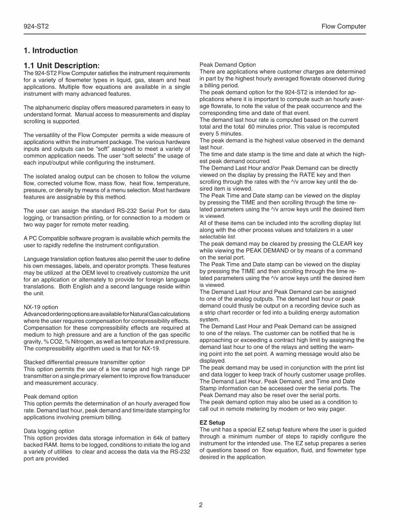
Peak Demand OptionThere are applications where customer charges are determined in part by the highest hourly averaged fl owrate observed during a billing period.The peak demand option for the 924-ST2 is intended for ap-plications where it is important to compute such an hourly aver-age fl owrate, to note the value of the peak occurrence and the corresponding time and date of that event.The demand last hour rate is computed based on the current total and the total 60 minutes prior. This value is recomputed every 5 minutes.The peak demand is the highest value observed in the demand last hour.The time and date stamp is the time and date at which the high-est peak demand occurred.The Demand Last Hour and/or Peak Demand can be directly viewed on the display by pressing the RATE key and then scrolling through the rates with the ^/v arrow key until the de-sired item is viewed.The Peak Time and Date stamp can be viewed on the display by pressing the TIME and then scrolling through the time re-lated parameters using the ^/v arrow keys until the desired item is viewed.All of these items can be included into the scrolling display list along with the other process values and totalizers in a user selectable list.The peak demand may be cleared by pressing the CLEAR key while viewing the PEAK DEMAND or by means of a command on the serial port.The Peak Time and Date stamp can be viewed on the display by pressing the TIME and then scrolling through the time re-lated parameters using the ^/v arrow keys until the desired item is viewed.The Demand Last Hour and Peak Demand can be assigned to one of the analog outputs. The demand last hour or peak demand could thusly be output on a recording device such as a strip chart recorder or fed into a building energy automation system.The Demand Last Hour and Peak Demand can be assigned to one of the relays. The customer can be notifi ed that he is approaching or exceeding a contract high limit by assigning the demand last hour to one of the relays and setting the warn-ing point into the set point. A warning message would also be displayed.The peak demand may be used in conjunction with the print list and data logger to keep track of hourly customer usage profi les.The Demand Last Hour, Peak Demand, and Time and Date Stamp information can be accessed over the serial ports. The Peak Demand may also be reset over the serial ports.The peak demand option may also be used as a condition to call out in remote metering by modem or two way pager.
EZ SetupThe unit has a special EZ setup feature where the user is guided through a minimum number of steps to rapidly confi gure the instrument for the intended use. The EZ setup prepares a series of questions based on fl ow equation, fl uid, and fl owmeter type desired in the application.
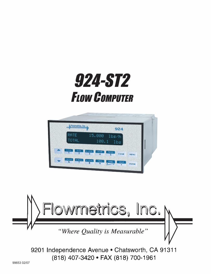
1.1 Unit Description:The 924-ST2 Flow Computer satisfi es the instrument requirements for a variety of fl owmeter types in liquid, gas, steam and heat applications. Multiple fl ow equations are available in a single instrument with many advanced features.
The alphanumeric display offers measured parameters in easy to understand format. Manual access to measurements and display scrolling is supported.
The versatility of the Flow Computer permits a wide measure of applications within the instrument package. The various hardware inputs and outputs can be “soft” assigned to meet a variety of common application needs. The user “soft selects” the usage of each input/output while confi guring the instrument.
The isolated analog output can be chosen to follow the volume fl ow, corrected volume fl ow, mass fl ow, heat fl ow, temperature, pressure, or density by means of a menu selection. Most hardware features are assignable by this method.
The user can assign the standard RS-232 Serial Port for data logging, or transaction printing, or for connection to a modem or two way pager for remote meter reading.
A PC Compatible software program is available which permits the user to rapidly redefi ne the instrument confi guration.
Language translation option features also permit the user to defi ne his own messages, labels, and operator prompts. These features may be utilized at the OEM level to creatively customize the unit for an application or alternately to provide for foreign language translations. Both English and a second language reside within the unit.
NX-19 optionAdvanced ordering options are available for Natural Gas calculations where the user requires compensation for compressibility effects. Compensation for these compressibility effects are required at medium to high pressure and are a function of the gas specifi c gravity, % CO2, % Nitrogen, as well as temperature and pressure. The compressibility algorithm used is that for NX-19.
Stacked differential pressure transmitter optionThis option permits the use of a low range and high range DP transmitter on a single primary element to improve fl ow transducer and measurement accuracy.
Peak demand optionThis option permits the determination of an hourly averaged fl ow rate. Demand last hour, peak demand and time/date stamping for applications involving premium billing.
Data logging optionThis option provides data storage information in 64k of battery backed RAM. Items to be logged, conditions to initiate the log and a variety of utilities to clear and access the data via the RS-232 port are provided.
3
924-ST2 Flow Computer
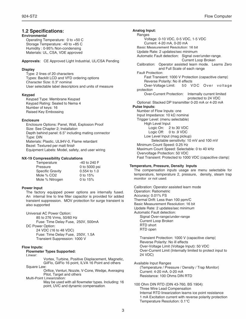
1.2 Specifi cations:Environmental
Operating Temperature: 0 to +50 CStorage Temperature: -40 to +85 CHumidity : 0-95% Non-condensingMaterials: UL, CSA, VDE approved
Approvals: CE Approved Light Industrial, UL/CSA Pending
DisplayType: 2 lines of 20 charactersTypes: Backlit LCD and VFD ordering optionsCharacter Size: 0.3" nominalUser selectable label descriptors and units of measure
KeypadKeypad Type: Membrane KeypadKeypad Rating: Sealed to Nema 4Number of keys: 16 Raised Key Embossing
EnclosureEnclosure Options: Panel, Wall, Explosion ProofSize: See Chapter 2; InstallationDepth behind panel: 6.5" including mating connectorType: DINMaterials: Plastic, UL94V-0, Flame retardantBezel: Textured per matt fi nishEquipment Labels: Model, safety, and user wiring
NX-19 Compressibility Calculations Temperature -40 to 240 F Pressure 0 to 5000 psi Specifi c Gravity 0.554 to 1.0 Mole % CO2 0 to 15% Mole % Nitrogen 0 to 15%
Power InputThe factory equipped power options are internally fused. An internal line to line fi lter capacitor is provided for added transient suppression. MOV protection for surge transient is also supported
Universal AC Power Option: 85 to 276 Vrms, 50/60 Hz Fuse: Time Delay Fuse, 250V, 500mADC Power Option: 24 VDC (16 to 48 VDC) Fuse: Time Delay Fuse, 250V, 1.5A Transient Suppression: 1000 V
Flow Inputs:Flowmeter Types Supported:Linear: Vortex, Turbine, Positive Displacement, Magnetic,
GilFlo, GilFlo 16 point, ILVA 16 Point and othersSquare Law: Orifi ce, Venturi, Nozzle, V-Cone, Wedge, Averaging
Pitot, Target and othersMulti-Point Linearization: May be used with all fl owmeter types. Including: 16
point, UVC and dynamic compensation.
Analog Input:Ranges Voltage: 0-10 VDC, 0-5 VDC, 1-5 VDC Current: 4-20 mA, 0-20 mABasic Measurement Resolution: 16 bitUpdate Rate: 2 updates/sec minimumAutomatic Fault detection: Signal over/under-range, Current Loop BrokenCalibration: Operator assisted learn mode. Learns Zero
and Full Scale of each rangeFault Protection: Fast Transient: 1000 V Protection (capacitive clamp) Reverse Polarity: No ill effects Over-Voltage Limit: 5 0 V D C O v e r v o l t a g e protection Over-Current Protection: Internally current limited protected to 24 VDCOptional: Stacked DP transmitter 0-20 mA or 4-20 mA
Pulse Inputs:Number of Flow Inputs: one Input Impedance: 10 kΩ nominalTrigger Level: (menu selectable) High Level Input Logic On: 2 to 30 VDC Logic Off: 0 to .9 VDC Low Level Input (mag pickup) Selectable sensitivity: 10 mV and 100 mV Minimum Count Speed: 0.25 HzMaximum Count Speed: Selectable: 0 to 40 kHzOvervoltage Protection: 50 VDCFast Transient: Protected to 1000 VDC (capacitive clamp)
Temperature, Pressure, Density InputsThe compensation inputs usage are menu selectable for temperature, temperature 2, pressure, density, steam trap monitor or not used.
Calibration: Operator assisted learn modeOperation: Ratiometric Accuracy: 0.01% FSThermal Drift: Less than 100 ppm/CBasic Measurement Resolution: 16 bitUpdate Rate: 2 updates/sec minimumAutomatic Fault detection: Signal Over-range/under-range Current Loop Broken RTD short RTD open
Transient Protection: 1000 V (capacitive clamp) Reverse Polarity: No ill effects Over-Voltage Limit (Voltage Input): 50 VDC Over-Current Limit (Internally limited to protect input to 24 VDC)
Available Input Ranges (Temperature / Pressure / Density / Trap Monitor) Current: 4-20 mA, 0-20 mA Resistance: 100 Ohms DIN RTD
100 Ohm DIN RTD (DIN 43-760, BS 1904): Three Wire Lead Compensation Internal RTD linearization learns ice point resistance 1 mA Excitation current with reverse polarity protection Temperature Resolution: 0.1°C
4
924-ST2 Flow Computer
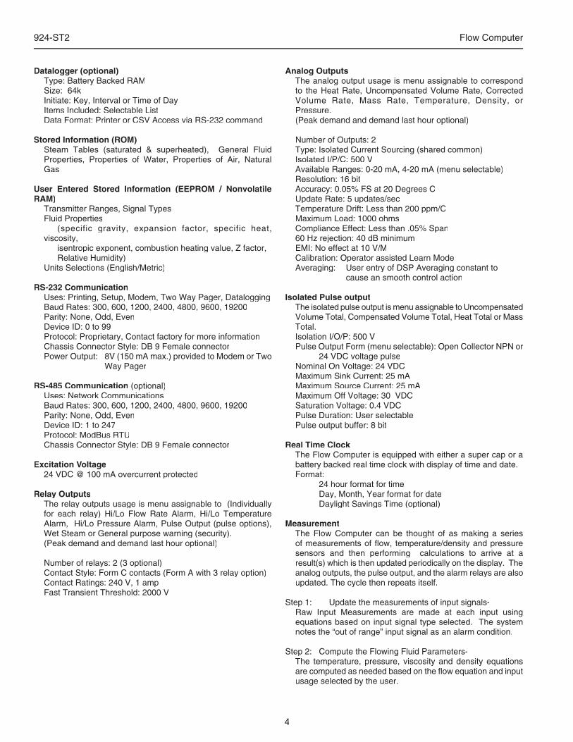
Datalogger (optional)Type: Battery Backed RAMSize: 64kInitiate: Key, Interval or Time of DayItems Included: Selectable ListData Format: Printer or CSV Access via RS-232 command
Stored Information (ROM)Steam Tables (saturated & superheated), General Fluid Properties, Properties of Water, Properties of Air, Natural Gas
User Entered Stored Information (EEPROM / Nonvolatile RAM)
Transmitter Ranges, Signal TypesFluid Properties (specific gravity, expansion factor, specific heat, viscosity, isentropic exponent, combustion heating value, Z factor, Relative Humidity) Units Selections (English/Metric)
RS-232 CommunicationUses: Printing, Setup, Modem, Two Way Pager, DataloggingBaud Rates: 300, 600, 1200, 2400, 4800, 9600, 19200Parity: None, Odd, EvenDevice ID: 0 to 99Protocol: Proprietary, Contact factory for more informationChassis Connector Style: DB 9 Female connectorPower Output: 8V (150 mA max.) provided to Modem or Two
Way Pager
RS-485 Communication (optional)Uses: Network CommunicationsBaud Rates: 300, 600, 1200, 2400, 4800, 9600, 19200Parity: None, Odd, EvenDevice ID: 1 to 247Protocol: ModBus RTUChassis Connector Style: DB 9 Female connector
Excitation Voltage24 VDC @ 100 mA overcurrent protected
Relay OutputsThe relay outputs usage is menu assignable to (Individually for each relay) Hi/Lo Flow Rate Alarm, Hi/Lo Temperature Alarm, Hi/Lo Pressure Alarm, Pulse Output (pulse options), Wet Steam or General purpose warning (security).(Peak demand and demand last hour optional)
Number of relays: 2 (3 optional)Contact Style: Form C contacts (Form A with 3 relay option)Contact Ratings: 240 V, 1 ampFast Transient Threshold: 2000 V
Analog OutputsThe analog output usage is menu assignable to correspond to the Heat Rate, Uncompensated Volume Rate, Corrected Volume Rate, Mass Rate, Temperature, Density, or Pressure.(Peak demand and demand last hour optional)
Number of Outputs: 2Type: Isolated Current Sourcing (shared common)Isolated I/P/C: 500 VAvailable Ranges: 0-20 mA, 4-20 mA (menu selectable)Resolution: 16 bitAccuracy: 0.05% FS at 20 Degrees CUpdate Rate: 5 updates/secTemperature Drift: Less than 200 ppm/CMaximum Load: 1000 ohmsCompliance Effect: Less than .05% Span60 Hz rejection: 40 dB minimumEMI: No effect at 10 V/MCalibration: Operator assisted Learn ModeAveraging: User entry of DSP Averaging constant to cause an smooth control action
Isolated Pulse outputThe isolated pulse output is menu assignable to Uncompensated Volume Total, Compensated Volume Total, Heat Total or Mass Total.Isolation I/O/P: 500 VPulse Output Form (menu selectable): Open Collector NPN or
24 VDC voltage pulseNominal On Voltage: 24 VDCMaximum Sink Current: 25 mAMaximum Source Current: 25 mAMaximum Off Voltage: 30 VDCSaturation Voltage: 0.4 VDCPulse Duration: User selectablePulse output buffer: 8 bit
Real Time ClockThe Flow Computer is equipped with either a super cap or a battery backed real time clock with display of time and date.Format: 24 hour format for time Day, Month, Year format for date Daylight Savings Time (optional)
MeasurementThe Flow Computer can be thought of as making a series of measurements of fl ow, temperature/density and pressure sensors and then performing calculations to arrive at a result(s) which is then updated periodically on the display. The analog outputs, the pulse output, and the alarm relays are also updated. The cycle then repeats itself.
Step 1: Update the measurements of input signals-Raw Input Measurements are made at each input using equations based on input signal type selected. The system notes the “out of range” input signal as an alarm condition.
Step 2: Compute the Flowing Fluid Parameters-The temperature, pressure, viscosity and density equations are computed as needed based on the fl ow equation and input usage selected by the user.
5
924-ST2 Flow Computer
Step 3 : Compute the Volumetric Flow-Volumetric fl ow is the term given to the fl ow in volume units. The value is computed based on the fl owmeter input type selected and augmented by any performance enhancing linearization that has been specifi ed by the user.
Step 4: Compute the Corrected Volume Flow at Reference Conditions-In the case of a corrected liquid or gas volume fl ow calculation, the corrected volume fl ow is computed as required by the selected compensation equation.
Step 5 : Compute the Mass Flow-All required information is now available to compute the mass fl ow rate as volume fl ow times density. A heat fl ow computation is also made if required.
Step 6: Check Flow Alarms-The fl ow alarm functions have been assigned to one of the above fl ow rates during the setup of the instrument. A comparison is now made by comparing the current fl ow rates against the specifi ed hi and low limits.
Step 7: Compute the Analog Output-This designated fl ow rate value is now used to compute the analog output.
Step 8: Compute the Flow Totals by Summation-A fl ow total increment is computed for each fl ow rate. This increment is computed by multiplying the respective fl ow rate by a time base scaler and then summing. The totalizer format also includes provisions for total rollover.
Step 9: Pulse Output Service-The pulse output is next updated by scaling the total increment which has just been determined by the pulse output scaler and summing it to any residual pulse output amount.
Step 10: Update Display and Printer Output-The instrument fi nally runs a task to update the various table entries associated with the front panel display and serial outputs.
Instrument Setup The setup is password protected by means of a numeric lock out code established by the user. The help line and units of measure prompts assure easy entry of parameters.
An EZ Setup function is supported to rapidly confi gure the instrument for fi rst time use. A software program is also available which runs on a PC using a RS-232 Serial for connection to the Flow Computer. Illustrative examples may be down loaded in this manner.
The standard setup menu has numerous subgrouping of parameters needed for fl ow calculations. There is a well conceived hierarchy to the setup parameter list. Selections made at the beginning of the setup automatically affect offerings further down in the lists, minimizing the number of questions asked of the user.
In the setup menu, the fl ow computer activates the correct setup variables based on the instrument confi guration, the fl ow equation, and the hardware selections made for the compensation transmitter type, the fl ow transmitter type, and meter enhancements (linearization) options selected. All required setup parameters are enabled. All setup parameters not required are suppressed.
Also note that in the menu are parameter selections which have preassigned industry standard values. The unit will assume these values unless they are modifi ed by the user.
Most of the process input variables have available a “default” or emergency value which must be entered. These are the values that the unit assumes when a malfunction is determined to have occurred on the corresponding input.
It is possible to enter in a nominal constant value for temperature or density, or pressure inputs by placing the desired nominal value into the default values and selecting "manual". This is also a convenience when performing bench top tests without simulators.
The system also provides a minimum implementation of an “audit trail” which tracks signifi cant setup changes to the unit. This feature is increasingly being found of benefi t to users or simply required by Weights and Measurement Offi cials in systems used in commerce, trade, or “custody transfer” applications.
Simulation and Self Checking:This mode provides a number of specialized utilities required for factory calibration, instrument checkout on start-up, and periodic calibration documentation.
A service password is required to gain access to this specialized mode of operation. Normally quality, calibration, and maintenance personnel will fi nd this mode of operation very useful.
Many of these tests may be used during start-up of a new system. Output signals may be exercised to verify the electrical interconnects before the entire system is put on line.
The following action items may be performed in the Diagnostic Mode:
Print Calibration/Maintenance ReportView Signal Input (Voltage, Current, Resistance, Frequency)Examine Audit TrailPerform a Self TestPerform a Service TestView Error HistoryPerform Pulse Output Checkout / SimulationPerform Relay Output Checkout / SimulationPerform Analog Output Checkout / SimulationCalibrate Analog Inputs using the Learn FeatureCalibrate Analog Output using the Learn FeatureSchedule Next Maintenance Date
Note that a calibration of the analog input/output will advance the audit trail counters since it effects the accuracy of the system.
6
924-ST2 Flow Computer
Operation of Steam Trap MonitorIn applications on Saturated Steam, the otherwise unused Compensation Input may be connected to a steam trap monitor that offers the following compatible output signal levels:4mA = trap cold12 mA = trap warm and open (blowing) 20 mA = trap warm and closed
In normal operation a steam trap is warm and periodically opens and closes in response to the accumulation of condensate. A cold trap is indication that it is not purging the condensate, a trap that is constantly blowing is an indication that it is stuck open. To avoid a false alarm, the 924-ST2 permits the user to program a delay, or time period, which should be considered normal for the trap to be either cold, or open. An alarm will only be activated if the trap is detected as continuously being in the abnormal states for a time period greater than this TRAP ERROR DELAY time.
The user selects to use the Compensation Input for Trap Monitoring by selecting “4-20mA TRAP STATUS as the INPUT SIGNAL for OTHER INPUT1.
The user can program the ERROR DELAY time in HH:MM format into both the TRAP ERROR DELAY (cold trap error) menu and the TRAP BLOWING DELAY (trap stuck open) menu.
The 924-ST2 will warn the operator of a TRAP ERROR when an abnormal condition is detected. The error can be acknowledged by pressing the ENTER key. However, the problem may reassert itself if there is a continued problem with the steam trap.
In addition, the event is noted in the ERROR LOG.
It is also possible for the user to program a trap malfunction as one of the conditions worthy of a CALL OUT of a problem by selecting this error in the ERROR MASK.
The Data-Logging option of the 924-ST2 can also be used to log the performance of the trap by storing the % of time the trap has been cold, and/or blowing open during the datalog interval.
Datalogging OptionThe Datalogging Option for the 924-ST2 permits the user to automatically store sets of data items as a record on a periodic basis. A datalog record may be stored as the result of either a PRINT key depression, or an INTERVAL, or a TIME OF DAY request for a datalog.
The user defi nes the list of items to be included in each datalog by selecting these in the PRINT LIST menu located within the COMMUNICATIONS SUBMENU.
The user selects what will trigger a datalog record being stored in the PRINT INITIATE menu. The choices are PRINT KEY, INTERVAL, and TIME OF DAY.
The user can select the datalog store interval in a HH:MM format in the PRINT INTERVAL menu.
The user can also select the store time of day in a 24 hr HH:MM format in the PRINT TIME menu.
The user can also defi ne whether he just wants the data stored into the datalogger, or if he wants the data both stored in the datalogger and sent out over the RS232 port in the DATALOG ONLY menu.
The user can defi ne the format he wishes the data to be output in using the DATALOG FORMAT menu. Choices are PRINTER and DATABASE. PRINTER format will output the data records in a form suitable to dump to a printer. DATABASE format will output the values in a CSV, or Comma Separated Variable with Carriage return delimiting of each record.
A number of serial commands are also included to access and manipulate information stored with in the datalogger. Among these RS232 command capabilities are the following actions:
Clear Data LoggerSend all Data in DataloggerSend Only New Data since Datalogger was last ReadSend Data for the date included in the requestSend the column heading text for the CSV data fi eldsSend the column units of measure text for the CSV data
fi eldsStore one new record into datalogger nowRead Number of New Records in the dataloggerRead number of records currently in the dataloggerRead the maximum number of records capacity of the
dataloggerMove Pointer Back N recordsDump Record at PointerDump records newer than pointerDump data from N records back
The datalogger option is used in conjunction with the RS-232 port in remote metering applications.
The technical details associated with the serial commands are listed in Universal Serial Protocol Manual available upon request.RS-232 Serial Port
The Flow Computer has a general purpose RS-232 Port which may be used for any one of the following purposes:
Transaction Printing Data Logging Remote Metering by Modem Remote Metering by Two Way Pager Computer Communication Link Confi guration by Computer Print System Setup Print Calibration/Malfunction History
Instrument Setup by PC’s over Serial PortA Diskette program is provided with the Flow Computer that enables the user to rapidly confi gure the Flow Computer using an Personnel Computer. Included on the diskette are common instrument applications which may be used as a starting point for your application. This permits the user to have an excellent starting point and helps speed the user through the instrument setup.
7
924-ST2 Flow Computer
Operation of Serial Communication Port with Printers The Flow Computer’s RS-232 channel supports a number of operating modes. One of these modes is intended to support operation with a printer in metering applications requiring transaction printing, data logging and/or printing of calibration and maintenance reports.
For transaction printing, the user defi nes the items to be included in the printed document. The user can also select what initiates the transaction print generated as part of the setup of the instrument. The transaction document may be initiated via a front panel key depression.
In data logging, the user defi nes the items to be included in each data log as a print list. The user can also select when or how often he wishes a data log to be made. This is done during the setup of the instrument as either a time of day or as a time interval between logging.
The system setup and maintenance report list all the instrument setup parameters and usage for the current instrument configuration. In addition, the Audit trail information is presented as well as a status report listing any observed malfunctions which have not been corrected.
The user initiates the printing of this report at a designated point in the menu by pressing the print key on the front panel.
Operating Serial Communication Port with ModemsThe 924-ST2 offers a number of capabilities that facilitate its use with modems. The 924-ST2’s RS232 port can be connected to a modem in order to implement a remote metering system that uses either the phone companies standard phone lines or cellular telephone system. In addition to remote meter readings, the serial commands may also be used to examine and/or make setup changes to the unit, and to check for proper operation or investigate problems. Several hundred commands are supported. A compatible industrial modem accessory and interconnecting cabling is offered in the MPP2400N specifi cally designed for use with the 924-ST2.
The 924-ST2 and Modem can be used together to create systems with one or more of the following capabilities:1. Poll the 924-ST2 unit for information from a remote
PC.2. Call Out from the 924-ST2 unit to a remote PC on a
scheduled reading time and/or crisis basis3. Some combination of the above two descriptions where
the unit is polled by one PC and calls into to a different PC if a problem is detected.
In fact, up to fi ve ST-2 units can share the same modem. Each 924-ST2 must have a unique DEVICE ID. This multidropping of fl ow computers on a single modem is popular when there are several fl ow computers mounted near each other.
In most applications using modem communications, the 924-ST2’s RS232 USAGE is fi rst set equal to MODEM. Each 924-ST2 on a shared modem cable is given a unique serial device address or DEVICE ID. The BAUD RATE is commonly set to 2400, the PARITY set to NONE, and the HANSHAKING set to NONE to complete the basic setup.
The remote PC’s communication settings are chosen to match these.
The level of complexity of the Supetrol-2 to Modem connection can range from simple to more complex.
In a simple system a remote PC will call into the telephone number of the modem. The modem will answer the call, and establish a connection between the 924-ST2 and the remote PC. An exchange of information can now occur. The 924-ST2 will act as a slave and respond to commands and requests for information from the remote MASTER PC. The MASTER PC will end the exchange by handing up.
However, it is more common that the 924-ST2 will be used to control the modem. In these applications the following communication menu settings would be used: RS232 USAGE = MODEM DEVICE ID, BAUD RATE, PARITY, and
HANDSHAKING are set MODEM CONTROL = YES DEVICE MASTER = YES (When multidropping
several 924-ST2's, only one unit will be the DEVICE MASTER)
MODEM AUTO ANSWER = YES (This instructs the unit to answer incoming calls)
HANG UP IF INACTIVE = YES (This instructs the unit to hang up the line if no activities occur within several minutes).
A more complex form of a remote metering system can be implemented where the 924-ST2 will initiate a call to contact the remote PC at a scheduled time and/or in the event of a problem that has been detected. In these applications the 924-ST2 has additional setup capabilities including: The 924-ST2 must have a unique identifi er assigned
to it (using the TAG NUMBER) Call Out Telephone number must be entered in the
CALL OUT NUMBER The scheduled call out time for the daily reading must
be entered in CALL OUT TIME A decision must be made whether the unit will be used
to call on error(s) in CALL ON ERROR The particular error conditions to call out on must be
defi ned in the ERROR MASK The NUMBER OF REDIALS to be attempted if line is
busy must be entered in that cell HANG UP IF INACTIVE= YES will disconnect the call
if remote computer does not respond.
Consult the Universal Serial Commands User Manual for details on the individual commands supported by the 924-ST2. Contact the Flow Applications Group for a discussion on the remote metering system capabilities you are considering.
NOTE: Some modems can be confi gured in advance to answer incoming calls, terminate phone connections if communications is lost. In such applications there may be no need for the 924-ST2 to be functioning to “control” the modem. Setting the RS233 USAGE = COMPUTER will likely work.
8
924-ST2 Flow Computer
Operating Serial Communication Port with Two Way Paging
The 924-ST2 offers a number of capabilities that facilitate its use with two way paging systems. The 924-ST2’s RS232 port can be connected to a compatible two way pager transceiver in order to implement a wireless, two way paging, remote metering system. A compatible, industrial Two Way Pager Transceiver accessory is offered in the TWPNW specifi cally designed for use with the 924-ST2. A monthly service contract with a two way paging provider, for example Skytel, is required. The remote user or system sends or receives information from the 924-ST2 using either a Two Way Pager, such as Motorola’s Pagerwriter 2000 pager, or by email via the INTERNET.
In addition to obtaining remote meter readings, the serial commands may also be used to examine and/or make setup changes to the unit, and/or to check for proper operation or investigate problems. Several hundred commands are supported.
The 924-ST2 and TWPNW can be used together to create systems with one or more of the following capabilities:1. Poll the 924-ST2 unit for information from a remote PC
over the Internet via email.2. Call Out from the 924-ST2 unit to a remote PC on a
scheduled reading time and/or crisis basis by email and the internet
3. Some combination of the above two descriptions where the unit is polled by one PC and calls into to a different PC or pager if a problem is detected.
In fact, up to fi ve ST-2 units can share the same Two Way Pager. Each 924-ST2 must have a unique DEVICE ID. This multidropping of fl ow computers on a single Two Way Pager is popular when there are several fl ow computers mounted near each other.
The 924-ST2’s RS232 USAGE is fi rst set equal to PAGER. Each 924-ST2 on a shared PAGER is given a unique serial device address or DEVICE ID. The BAUD RATE is commonly set to 9600, the PARITY set to NONE, and the HANSHAKING set to NONE to complete the basic setup.
In a simple system, the 924-ST2 will send an email to an address programmed into the unit. The recipient will receive a daily email report containing the information desired in the form of a readable report.
To setup the information to be sent in this example: Setup your desired PRINT LIST Setup what will initiate the storage of information in
the PRINT INITIATE menu Setup any related parameters: PRINT INTERVAL or
PRINT TIME Set DATALOG ONLY = YES if data records will be sent at a later time = NO if data records will
be sent immediately as well as being stored Set DATALOG FORMAT = PRINTER
To setup the communication channel, the following communication menu settings would be used: RS232 USAGE = PAGER Set the DEVICE ID, BAUD RATE= 9600, PARITY= NONE, HANDSHAKING=NONE DEVICE MASTER = YES (When multidropping
several 924-ST2, only one unit will be the DEVICE MASTER)
CALL OUT NUMBER = <email name of receiver> or <PIN of receiving PAGER>
CALL OUT TIME = time of a scheduled call out in HH:MM format (if used set a different call out time to each unit, several hours apart)
NUMBER OF REDIALS = 3 (if there is poor coverage unit will try to up to 3 times)
PAGER PIN NUMBER = <enter the Pager Pin Number given you by Skytel >
DESTINATION TYPE= E-MAIL (or PAGER PIN if pager or mailbox)
MAX BLOCK SIZE = 3 (This is number of blocks (1- 4) of 128 bytes to be sent in each message. A smaller number of blocks increases the chance of successful communication transfers.
If you also wish the unit to CALL OUT in the event of a problem, the following menu settings would be used: CALL ON ERROR = YES ERROR MASK confi gured to suit the applications needs
Initial Installation and Startup
When a 924-ST2 / TWP pair are fi rst put on line, several service actions are required. These include:1. Allow time for the 924-ST2 to charge the batteries in
the TWPNW (see note below)2. Set up an account with Skytel and choose a suitable
service plan for this application3. Initializing the Pager using the 924-ST2 INITIALIZE
PAGER utility4. Registering the pager with Skytel using the 924-ST2
REGISTER PAGER utility5. Observe a sample exchange of information between
the 924-ST2 and the remote user using the CLP PROGRESS
9
924-ST2 Flow Computer
NOTE: It is important to wait 24 hours for the Two Way Pager Transceiver to charge its batteries prior to initial use. Otherwise irradic problems may occur during registration.
Special Utilities for steps 3, 4, and 5 are built into the 924-ST2. These may be summarized as follows:
INITIALIZE PAGER = YES causes the 924-ST2 to send commands to initialize the pager. The responses to the command can be either SUCCESS if all is well or FAILED if a problem is detected.
REGISTER PAGER = YES causes the 924-ST2 to attempt to establish a connection with a local Skytel tower. A series of informative messages will appear as the 924-ST2 attempts to register your PAGER PIN NUMBER with Skytel. Note that your service plan must be setup with Skytel before attempting to register the pager.
The responses to the command can be either SUCCESS if all is well or FAILED if a problem is detected.
CLP PROGRESS is a diagnostic menu location that provides information on the information exchanges for test purposes (see CLP Progress Menu in chapter 6). Contact the applications group if problems are encountered in initial setup or use of two way paging applications.
A more complex form of a remote metering system can be implemented where the 924-ST2 will initiate a call to a “mailbox” at Skytel. The Remote PC can access his mailbox and read and process the various messages over the internet as part of a customer billing system. Skytel offers a software developers kit for customers wishing to create custom solutions.
In each message, the 924-ST2 provides a header containing
information that can be used to determine such items as:1. What is the TAG NO of the device that sent the
information?2. What is its SENSOR SN3. What is its DEVICE ID? 4. What type of message follows?a. Exception Report (Message Type-1)b. Send one Data Set (Message Type 2)c. Send all new Datalog Data Sets (Message type 3)5. What is the time and data of the fi rst data record?6. What information is contained in the data fi elds of CSV
that follow?7. Message Delimiter (CRLF)8. For commands returning data, the data now follows in
a CSV format
Consult the Universal Serial Commands User Manual for details on the individual commands supported by the 924-ST2.
Contact the Flow Applications Group for a discussion on the remote metering system capabilities you are considering.
RS-485 Serial Port (optional)The RS-485 serial port can be used for accessing fl ow rate, total, pressure, temperature, density and alarm status information. The port can also be used for changing presets and acknowledging alarms.
10
924-ST2 Flow Computer
2. Installation
2.1 General Mounting Hints:
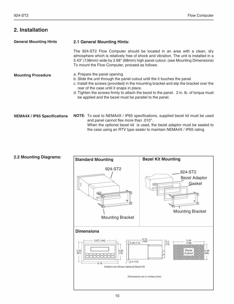
The 924-ST2 Flow Computer should be located in an area with a clean, dry atmosphere which is relatively free of shock and vibration. The unit is installed in a 5.43" (138mm) wide by 2.68" (68mm) high panel cutout. (see Mounting Dimensions) To mount the Flow Computer, proceed as follows:
a. Prepare the panel opening.b. Slide the unit through the panel cutout until the it touches the panel.c. Install the screws (provided) in the mounting bracket and slip the bracket over the
rear of the case until it snaps in place.d. Tighten the screws fi rmly to attach the bezel to the panel. 3 in. lb. of torque must
be applied and the bezel must be parallel to the panel.
NOTE: To seal to NEMA4X / IP65 specifi cations, supplied bezel kit must be used and panel cannot fl ex more than .010".
When the optional bezel kit is used, the bezel adaptor must be sealed to the case using an RTV type sealer to maintain NEMA4X / IP65 rating.
General Mounting Hints
Mounting Procedure
NEMA4X / IP65 Specifi cations
924-ST2924-ST2Bezel AdaptorBezel Adaptor
GasketGasketGasketBezel Adaptor
Mounting BracketMounting Bracket
Standard Mounting Bezel Kit Mounting
Dimensions
Dotted Line Shows Optional Bezel Kit
PanelCutout
5.43(138)
2.68(68)
Dimensions are in inches (mm)
5.67 (144)
2.83(72)
3.43(87)
6.18
6.15(156) 0.5
(13)0.28 (7.2)
0.4 (10)
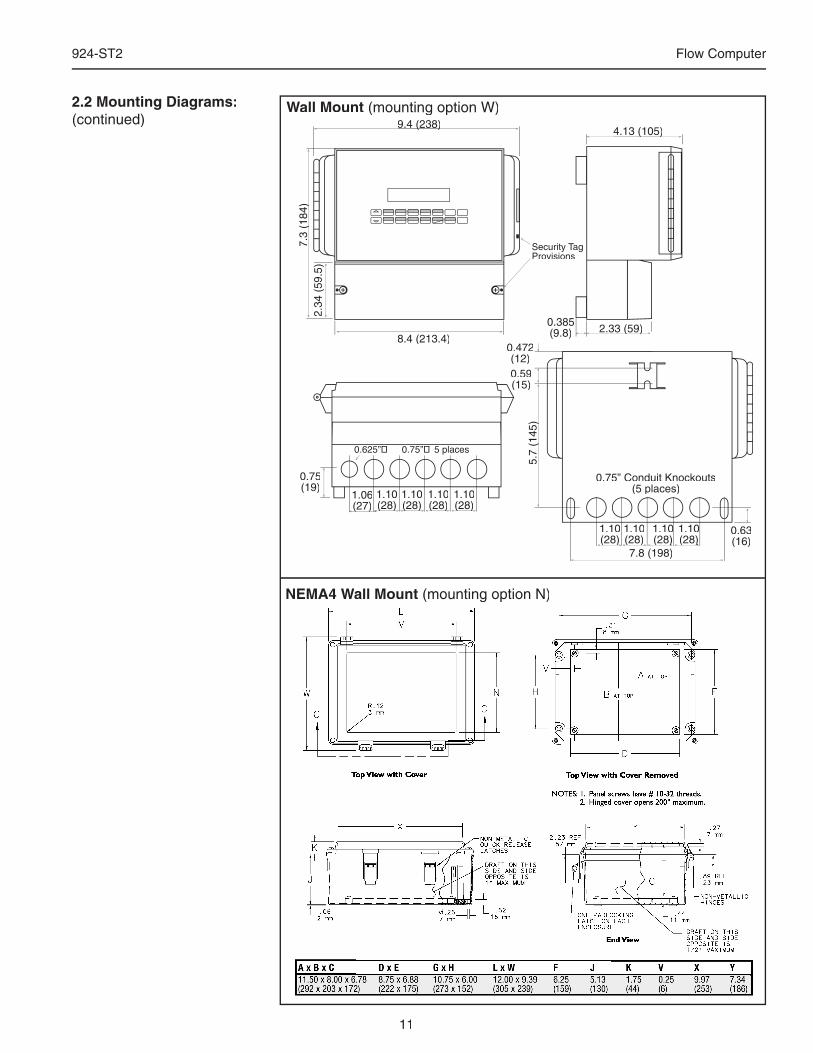
2.2 Mounting Diagrams:
11
924-ST2 Flow Computer
1.10(28)(28)
1.101.10(28)(28)(28)
7.8 (198)
5.7
(145
)5.
7 (1
45)
0.59(15)
0.75” Conduit Knockouts(5 places)1.06
(27)(27)
9.4 (238)9.4 (238)
7.3
(184
)7.
3 (1
84)
2.34
(59
.5)
8.4 (213.4)
4.13 (105)4.13 (105)
2.33 (59)2.33 (59)0.385(9.8)
Security TagProvisions
1.10(28)(28)(28)
1.10(28)(28)(28)
1.10(28)(28)
1.10(28)(28)(28)
1.10(28)(28)
1.10(28)(28)
0.472(12)
0.75(19)
0.63(16)
Wall Mount (mounting option W)2.2 Mounting Diagrams:(continued)
NEMA4 Wall Mount (mounting option N)
12
924-ST2 Flow Computer
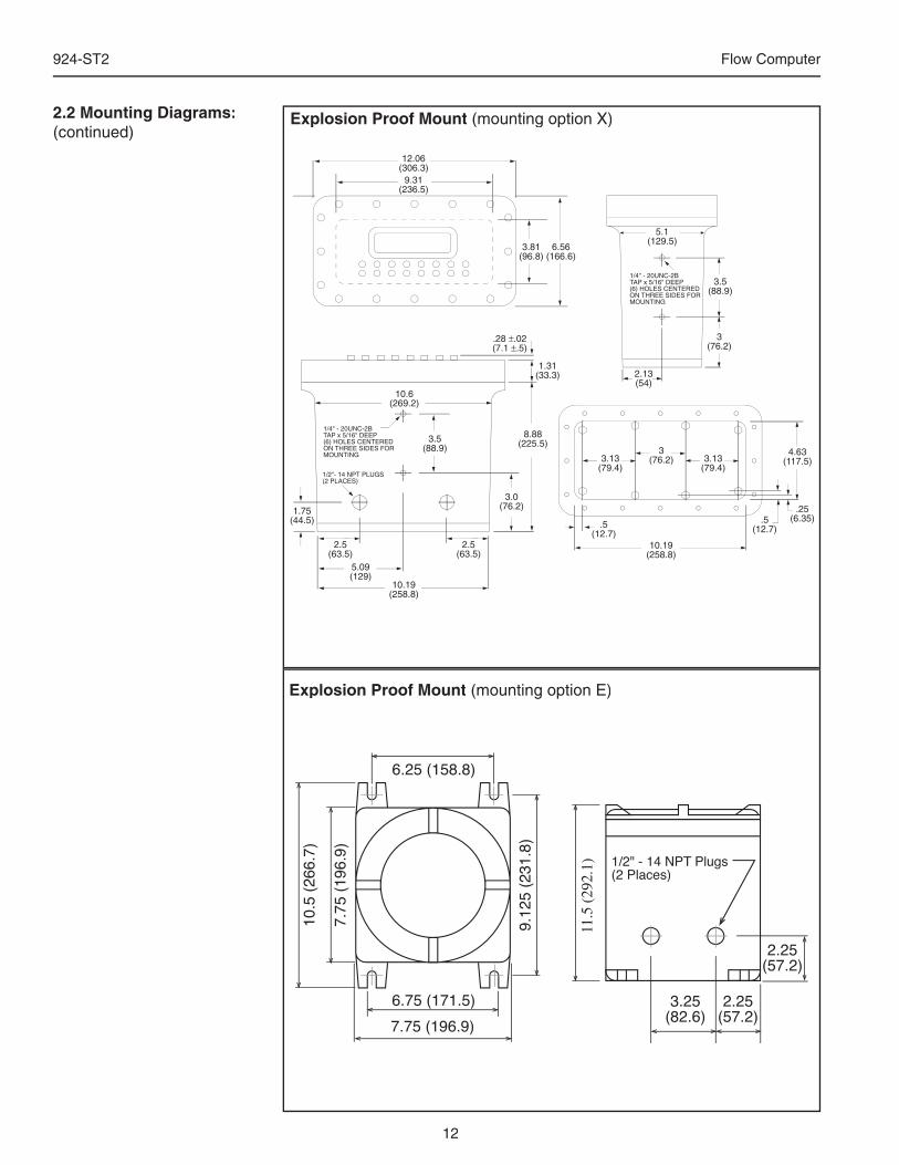
Explosion Proof Mount (mounting option X)2.2 Mounting Diagrams:(continued)
Explosion Proof Mount (mounting option E)
9.31(236.5)
12.06(306.3)
3.81(96.8)
6.56(166.6)
.28 ±.02(7.1 ±.5)
1.31(33.3)
8.88(225.5)3.5
(88.9)
10.19(258.8)
2.5(63.5)
2.5(63.5)
5.09(129)
3.0(76.2)
1/4" - 20UNC-2BTAP x 5/16" DEEP(6) HOLES CENTEREDON THREE SIDES FORMOUNTING
1/2"- 14 NPT PLUGS(2 PLACES)
10.6(269.2)
1/4" - 20UNC-2BTAP x 5/16" DEEP(6) HOLES CENTEREDON THREE SIDES FORMOUNTING
3.5(88.9)
3(76.2)
2.13(54)
1.75(44.5)
5.1(129.5)
.25(6.35).5
(12.7)
4.63(117.5)
10.19(258.8)
3.13(79.4)
3.13(79.4)
3(76.2)
.5(12.7)
13
924-ST2 Flow Computer
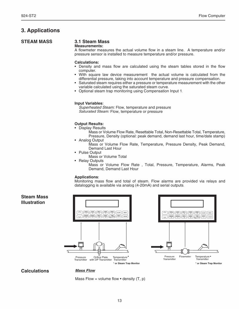
3.1 Steam MassMeasurements:A fl owmeter measures the actual volume fl ow in a steam line. A temperature and/or pressure sensor is installed to measure temperature and/or pressure.
Calculations:• Density and mass fl ow are calculated using the steam tables stored in the fl ow
computer. • With square law device measurement the actual volume is calculated from the
differential pressure, taking into account temperature and pressure compensation.• Saturated steam requires either a pressure or temperature measurement with the other
variable calculated using the saturated steam curve.• Optional steam trap monitoring using Compensation Input 1.
Input Variables:Superheated Steam: Flow, temperature and pressureSaturated Steam: Flow, temperature or pressure
Output Results:• Display Results Mass or Volume Flow Rate, Resettable Total, Non-Resettable Total, Temperature,
Pressure, Density (optional: peak demand, demand last hour, time/date stamp)• Analog Output Mass or Volume Flow Rate, Temperature, Pressure Density, Peak Demand,
Demand Last Hour• Pulse Output Mass or Volume Total• Relay Outputs Mass or Volume Flow Rate , Total, Pressure, Temperature, Alarms, Peak
Demand, Demand Last Hour
Applications:Monitoring mass fl ow and total of steam. Flow alarms are provided via relays and datalogging is available via analog (4-20mA) and serial outputs.
STEAM MASS
Steam MassIllustration
3. Applications
Flowmeter Temperaturer Temperaturer TTransmitter
PRINT5
0 –
TIME
CLEAR
•
MENU
ENTERHELP
TEMP4
PRE 13
RATE2
TOTAL1
GRAND6
SCROLL7
PRE 28
DENS9
PressureTransmitter
Mass Flow
Mass Flow = volume fl ow • density (T, p)
Calculations
*
* or Steam Trap Monitor
*
* or Steam Trap Monitor
14
924-ST2 Flow Computer
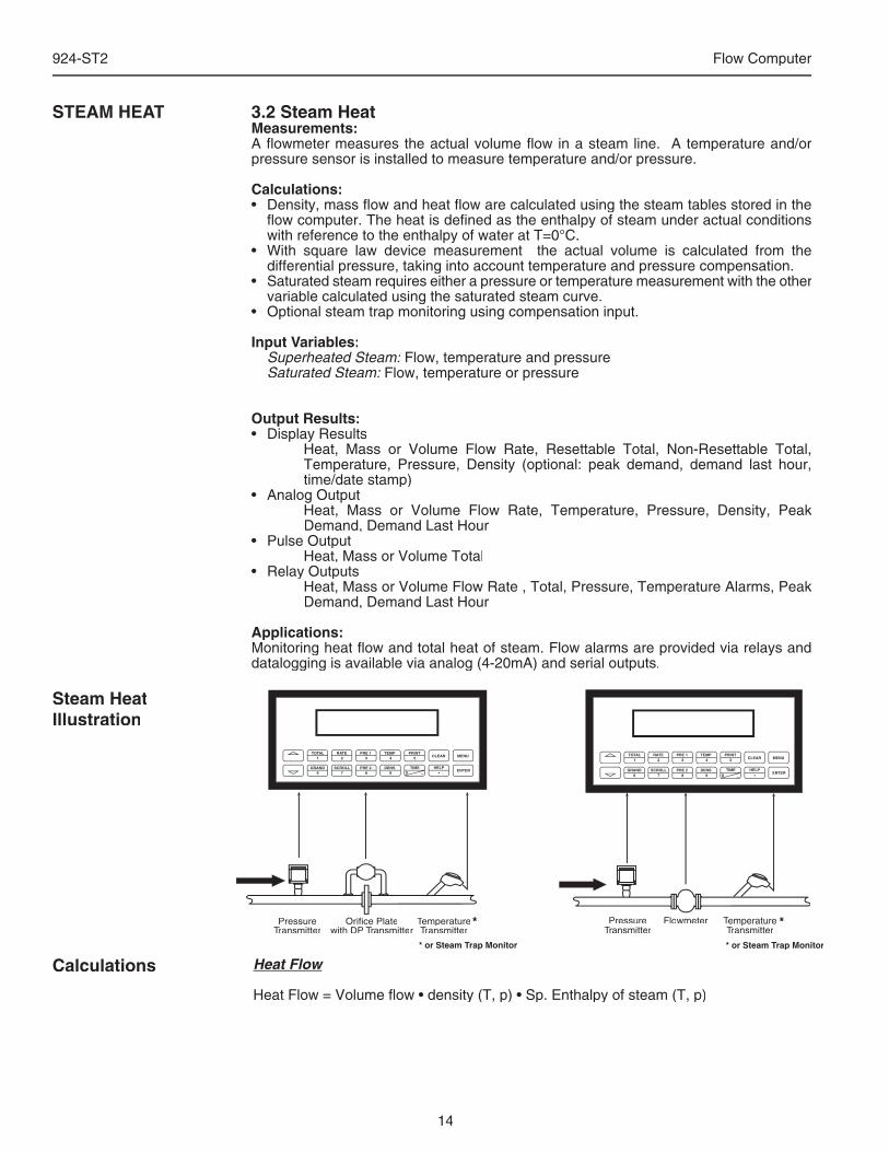
3.2 Steam HeatMeasurements:A fl owmeter measures the actual volume fl ow in a steam line. A temperature and/or pressure sensor is installed to measure temperature and/or pressure.
Calculations:• Density, mass fl ow and heat fl ow are calculated using the steam tables stored in the
fl ow computer. The heat is defi ned as the enthalpy of steam under actual conditions with reference to the enthalpy of water at T=0°C.
• With square law device measurement the actual volume is calculated from the differential pressure, taking into account temperature and pressure compensation.
• Saturated steam requires either a pressure or temperature measurement with the other variable calculated using the saturated steam curve.
• Optional steam trap monitoring using compensation input.
Input Variables:Superheated Steam: Flow, temperature and pressureSaturated Steam: Flow, temperature or pressure
Output Results:• Display Results Heat, Mass or Volume Flow Rate, Resettable Total, Non-Resettable Total,
Temperature, Pressure, Density (optional: peak demand, demand last hour, time/date stamp)
• Analog Output Heat, Mass or Volume Flow Rate, Temperature, Pressure, Density, Peak
Demand, Demand Last Hour• Pulse Output Heat, Mass or Volume Total• Relay Outputs Heat, Mass or Volume Flow Rate , Total, Pressure, Temperature Alarms, Peak
Demand, Demand Last Hour
Applications:Monitoring heat fl ow and total heat of steam. Flow alarms are provided via relays and datalogging is available via analog (4-20mA) and serial outputs.
STEAM HEAT
Heat Flow
Heat Flow = Volume fl ow • density (T, p) • Sp. Enthalpy of steam (T, p)
Calculations
Steam HeatIllustration
TemperatureTemperatureTTransmitter
PRINT5
0 –
TIME
CLEAR
•
MENU
ENTERHELP
TEMP4
PRE 13
RATE2
TOTAL1
GRAND6
SCROLL7
PRE 28
DENS9
PressureTransmitter
Orifice Platewith DP Transmitter
Flowmeter Temperaturer Temperaturer TTransmitter
PRINT5
0 –
TIME
CLEAR
•
MENU
ENTERHELP
TEMP4
PRE 13
RATE2
TOTAL1
GRAND6
SCROLL7
PRE 28
DENS9
PressureTransmitter
*
* or Steam Trap Monitor
*
* or Steam Trap Monitor
15
924-ST2 Flow Computer
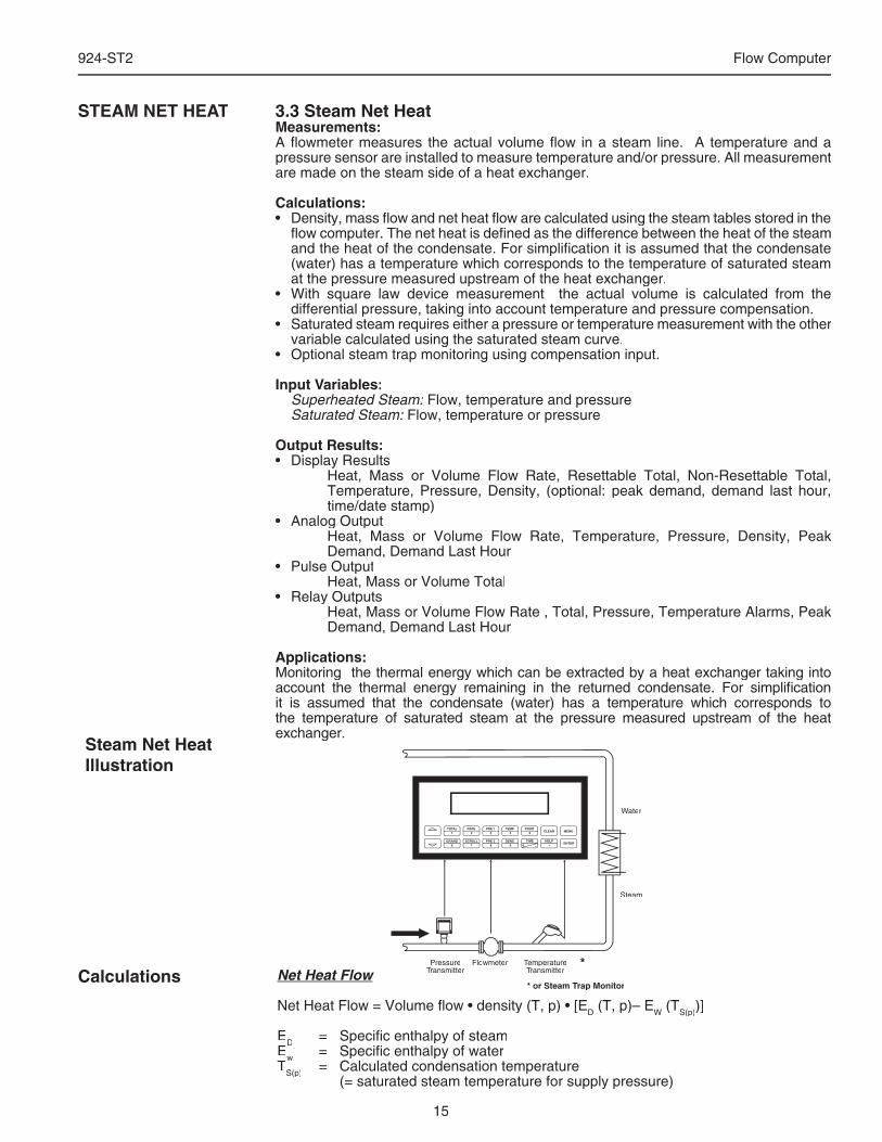
3.3 Steam Net HeatMeasurements:A fl owmeter measures the actual volume fl ow in a steam line. A temperature and a pressure sensor are installed to measure temperature and/or pressure. All measurement are made on the steam side of a heat exchanger.
Calculations:• Density, mass fl ow and net heat fl ow are calculated using the steam tables stored in the
fl ow computer. The net heat is defi ned as the difference between the heat of the steam and the heat of the condensate. For simplifi cation it is assumed that the condensate (water) has a temperature which corresponds to the temperature of saturated steam at the pressure measured upstream of the heat exchanger.
• With square law device measurement the actual volume is calculated from the differential pressure, taking into account temperature and pressure compensation.
• Saturated steam requires either a pressure or temperature measurement with the other variable calculated using the saturated steam curve.
• Optional steam trap monitoring using compensation input.
Input Variables:Superheated Steam: Flow, temperature and pressureSaturated Steam: Flow, temperature or pressure
Output Results:• Display Results Heat, Mass or Volume Flow Rate, Resettable Total, Non-Resettable Total,
Temperature, Pressure, Density, (optional: peak demand, demand last hour, time/date stamp)
• Analog Output Heat, Mass or Volume Flow Rate, Temperature, Pressure, Density, Peak
Demand, Demand Last Hour• Pulse Output Heat, Mass or Volume Total• Relay Outputs Heat, Mass or Volume Flow Rate , Total, Pressure, Temperature Alarms, Peak
Demand, Demand Last Hour
Applications:Monitoring the thermal energy which can be extracted by a heat exchanger taking into account the thermal energy remaining in the returned condensate. For simplifi cation it is assumed that the condensate (water) has a temperature which corresponds to the temperature of saturated steam at the pressure measured upstream of the heat exchanger.
STEAM NET HEAT
Net Heat Flow
Net Heat Flow = Volume fl ow • density (T, p) • [ED (T, p)– EW (TS(p))]
ED = Specifi c enthalpy of steamEw = Specifi c enthalpy of waterTS(p) = Calculated condensation temperature (= saturated steam temperature for supply pressure)
S(p) (= saturated steam temperature for supply pressure)
S(p)
Calculations
Steam Net HeatIllustration
Flowmeter Temperaturer Temperaturer TTransmitter
PRINT5
0 –
TIME
CLEAR
•
MENU
ENTERHELP
TEMP4
PRE 13
RATE2
TOTAL1
GRAND6
SCROLL7
PRE 28
DENS9
PressureTransmitter
Water
Steam
*
* or Steam Trap Monitor
16
924-ST2 Flow Computer
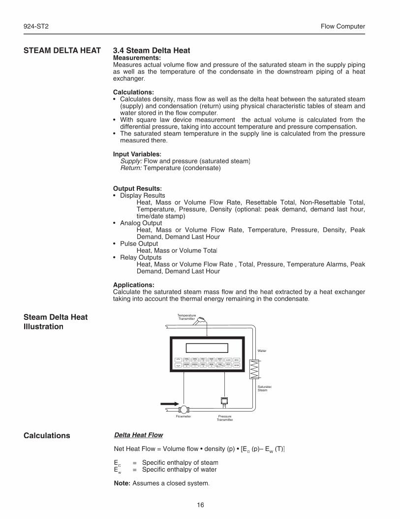
3.4 Steam Delta HeatMeasurements:Measures actual volume fl ow and pressure of the saturated steam in the supply piping as well as the temperature of the condensate in the downstream piping of a heat exchanger.
Calculations:• Calculates density, mass fl ow as well as the delta heat between the saturated steam
(supply) and condensation (return) using physical characteristic tables of steam and water stored in the fl ow computer.
• With square law device measurement the actual volume is calculated from the differential pressure, taking into account temperature and pressure compensation.
• The saturated steam temperature in the supply line is calculated from the pressure measured there.
Input Variables:Supply: Flow and pressure (saturated steam)Return: Temperature (condensate)
Output Results:• Display Results Heat, Mass or Volume Flow Rate, Resettable Total, Non-Resettable Total,
Temperature, Pressure, Density (optional: peak demand, demand last hour, time/date stamp)
• Analog Output Heat, Mass or Volume Flow Rate, Temperature, Pressure, Density, Peak
Demand, Demand Last Hour• Pulse Output Heat, Mass or Volume Total• Relay Outputs Heat, Mass or Volume Flow Rate , Total, Pressure, Temperature Alarms, Peak
Demand, Demand Last Hour
Applications:Calculate the saturated steam mass fl ow and the heat extracted by a heat exchanger taking into account the thermal energy remaining in the condensate.
STEAM DELTA HEAT
Delta Heat Flow
Net Heat Flow = Volume fl ow • density (p) • [ED (p)– EW (T)]
ED = Specifi c enthalpy of steamEw = Specifi c enthalpy of water
Note: Assumes a closed system.
Calculations
Steam Delta HeatIllustration
Flowmeter
TemperatureTemperatureTTransmitter
PRINT5
0 –
TIME
CLEAR
•
MENU
ENTERHELP
TEMP4
PRE 13
RATE2
TOTAL1
GRAND6
SCROLL7
PRE 28
DENS9
PressureTransmitter
Water
SaturatedSteam
17
924-ST2 Flow Computer
3.5 Corrected Gas Volume
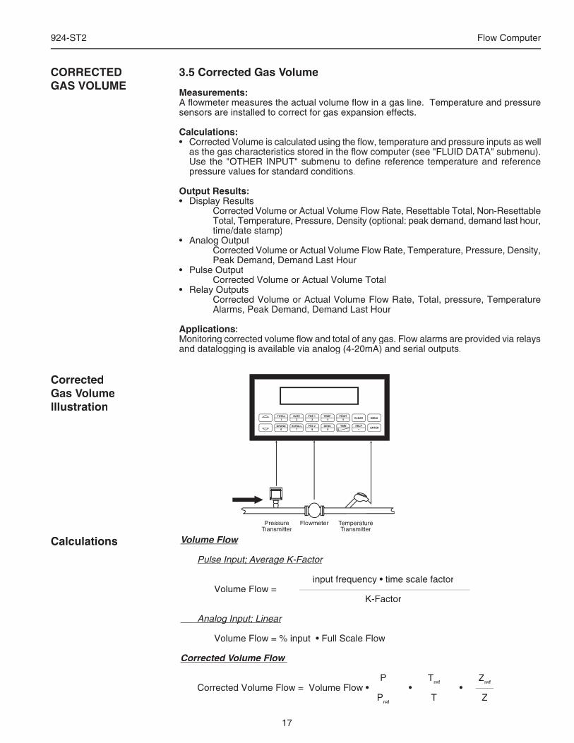
Measurements:A fl owmeter measures the actual volume fl ow in a gas line. Temperature and pressure sensors are installed to correct for gas expansion effects.
Calculations:• Corrected Volume is calculated using the fl ow, temperature and pressure inputs as well
as the gas characteristics stored in the fl ow computer (see "FLUID DATA" submenu). Use the "OTHER INPUT" submenu to defi ne reference temperature and reference pressure values for standard conditions.
Output Results:• Display Results Corrected Volume or Actual Volume Flow Rate, Resettable Total, Non-Resettable
Total, Temperature, Pressure, Density (optional: peak demand, demand last hour, time/date stamp)
• Analog Output Corrected Volume or Actual Volume Flow Rate, Temperature, Pressure, Density,
Peak Demand, Demand Last Hour• Pulse Output Corrected Volume or Actual Volume Total• Relay Outputs Corrected Volume or Actual Volume Flow Rate, Total, pressure, Temperature
Alarms, Peak Demand, Demand Last Hour
Applications:Monitoring corrected volume fl ow and total of any gas. Flow alarms are provided via relays and datalogging is available via analog (4-20mA) and serial outputs.
CORRECTEDGAS VOLUME
Volume Flow
Pulse Input; Average K-FactorPulse Input; Average K-Factor
input frequency • time scale factor Volume Flow = K-Factor
Analog Input; Linear Analog Input; Linear
Volume Flow = % input • Full Scale Flow
Corrected Volume Flow
P Tref Zref Corrected Volume Flow = Volume Flow • • •
ref Corrected Volume Flow = Volume Flow • • •
ref
Pref T Z
Calculations
CorrectedGas VolumeIllustration
Corrected Volume Flow = Volume Flow • • • Corrected Volume Flow = Volume Flow • • •
Flowmeter Temperaturer Temperaturer TTransmitter
PRINT5
0 –
TIME
CLEAR
•
MENU
ENTERHELP
TEMP4
PRE 13
RATE2
TOTAL1
GRAND6
SCROLL7
PRE 28
DENS9
PressureTransmitter
18
924-ST2 Flow Computer
TemperatureTemperatureTTransmitter
PRINT5
0 –
TIME
CLEAR
•
MENU
ENTERHELP
TEMP4
PRE 13
RATE2
TOTAL1
GRAND6
SCROLL7
PRE 28
DENS9
PressureTransmitter
Orifice Platewith DP Transmitter
Flowmeter Temperaturer Temperaturer TTransmitter
PRINT5
0 –
TIME
CLEAR
•
MENU
ENTERHELP
TEMP4
PRE 13
RATE2
TOTAL1
GRAND6
SCROLL7
PRE 28
DENS9
PressureTransmitter
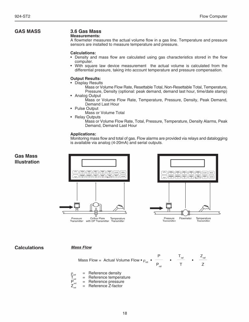
3.6 Gas MassMeasurements:A fl owmeter measures the actual volume fl ow in a gas line. Temperature and pressure sensors are installed to measure temperature and pressure.
Calculations:• Density and mass fl ow are calculated using gas characteristics stored in the fl ow
computer. • With square law device measurement the actual volume is calculated from the
differential pressure, taking into account temperature and pressure compensation.
Output Results:• Display Results Mass or Volume Flow Rate, Resettable Total, Non-Resettable Total, Temperature,
Pressure, Density (optional: peak demand, demand last hour, time/date stamp)• Analog Output Mass or Volume Flow Rate, Temperature, Pressure, Density, Peak Demand,
Demand Last Hour• Pulse Output Mass or Volume Total• Relay Outputs Mass or Volume Flow Rate, Total, Pressure, Temperature, Density Alarms, Peak
Demand, Demand Last Hour
Applications:Monitoring mass fl ow and total of gas. Flow alarms are provided via relays and datalogging is available via analog (4-20mA) and serial outputs.
GAS MASS
Mass Flow
P Tref Zref Mass Flow = Actual Volume Flow • ρref • • • P
ref P
ref
ref T Z
ρref = Reference densityT
refT
ref
ref = Reference temperaturePref = Reference pressureZref = Reference Z-factor
ref = Reference Z-factor
ref
Calculations
Gas MassIllustration
• • • • • •
19
924-ST2 Flow Computer
Flowmeter Temperaturer Temperaturer TTransmitter
PRINT5
0 –
TIME
CLEAR
•
MENU
ENTERHELP
TEMP4
PRE 13
RATE2
TOTAL1
GRAND6
SCROLL7
PRE 28
DENS9
PressureTransmitter
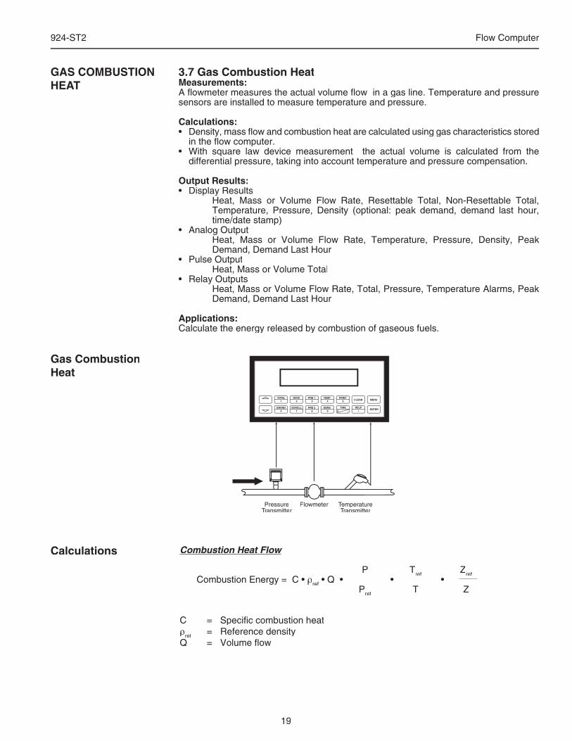
3.7 Gas Combustion HeatMeasurements:A fl owmeter measures the actual volume fl ow in a gas line. Temperature and pressure sensors are installed to measure temperature and pressure.
Calculations:• Density, mass fl ow and combustion heat are calculated using gas characteristics stored
in the fl ow computer. • With square law device measurement the actual volume is calculated from the
differential pressure, taking into account temperature and pressure compensation.
Output Results:• Display Results Heat, Mass or Volume Flow Rate, Resettable Total, Non-Resettable Total,
Temperature, Pressure, Density (optional: peak demand, demand last hour, time/date stamp)
• Analog Output Heat, Mass or Volume Flow Rate, Temperature, Pressure, Density, Peak
Demand, Demand Last Hour• Pulse Output Heat, Mass or Volume Total• Relay Outputs Heat, Mass or Volume Flow Rate, Total, Pressure, Temperature Alarms, Peak
Demand, Demand Last Hour
Applications:Calculate the energy released by combustion of gaseous fuels.
GAS COMBUSTIONHEAT
Combustion Heat Flow
P Tref Zref Combustion Energy = C • ρref • Q • • •
ref • Q • • •
ref
Pref
Pref
ref T Z
C = Specifi c combustion heatρref = Reference densityQ = Volume fl ow
Calculations
Gas CombustionHeat
• Q • • • • Q • • •
20
924-ST2 Flow Computer
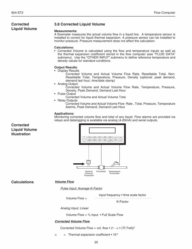
3.8 Corrected Liquid Volume
Measurements:A fl owmeter measures the actual volume fl ow in a liquid line. A temperature sensor is installed to correct for liquid thermal expansion. A pressure sensor can be installed to monitor pressure. Pressure measurement does not affect the calculation.
Calculations:• Corrected Volume is calculated using the fl ow and temperature inputs as well as
the thermal expansion coeffi cient stored in the fl ow computer (see "FLUID DATA" submenu). Use the "OTHER INPUT" submenu to defi ne reference temperature and density values for standard conditions.
Output Results:• Display Results Corrected Volume and Actual Volume Flow Rate, Resettable Total, Non-
Resettable Total, Temperature, Pressure, Density (optional: peak demand, demand last hour, time/date stamp)
• Analog Output Corrected Volume and Actual Volume Flow Rate, Temperature, Pressure,
Density, Peak Demand, Demand Last Hour• Pulse Output Corrected Volume and Actual Volume Total• Relay Outputs Corrected Volume and Actual Volume Flow Rate , Total, Pressure, Temperature
Alarms, Peak Demand, Demand Last Hour
Applications:Monitoring corrected volume fl ow and total of any liquid. Flow alarms are provided via relays and datalogging is available via analog (4-20mA) and serial outputs.
CorrectedLiquid Volume
Volume Flow
Pulse Input; Average K-FactorPulse Input; Average K-Factor
input frequency • time scale factor Volume Flow = K-Factor
Analog Input; Linear Analog Input; Linear
Volume Flow = % input • Full Scale Flow
Corrected Volume Flow
Corrected Volume Flow = vol. fl ow • (1 - α • (Tf-Tref))2
α = Thermal expansion coeffi cient • 10-6
Calculations
CorrectedLiquid VolumeIllustration
Flowmeter Temperaturer Temperaturer TTransmitter
PRINT5
0 –
TIME
CLEAR
•
MENU
ENTERHELP
TEMP4
PRE 13
RATE2
TOTAL1
GRAND6
SCROLL7
PRE 28
DENS9
OptionalPressure
Transmitter
924-ST2FLOW COMPUTER


924-ST2 Flow Computer
SAFETY INSTRUCTIONS .............................................................................................................11. INTRODUCTION 1.1 Unit Description ............................................................................................................2 1.2 Specifi cations ...............................................................................................................32. INSTALLATION 2.1 General Mounting Hints ..............................................................................................10 2.2 Mounting Diagrams ....................................................................................................103. APPLICATIONS 3.1 Steam Mass ................................................................................................................13 3.2 Steam Heat .................................................................................................................14 3.3 Steam Net Heat ..........................................................................................................15 3.4 Steam Delta Heat .......................................................................................................16 3.5 Corrected Gas Volume ...............................................................................................17 3.6 Gas Mass ...................................................................................................................18 3.7 Gas Combustion Heat ................................................................................................19 3.8 Corrected Liquid Volume ............................................................................................20 3.9 Liquid Mass ................................................................................................................21 3.10 Liquid Combustion Heat ...........................................................................................22 3.11 Liquid Sensible Heat .................................................................................................23 3.12 Liquid Delta Heat ......................................................................................................24
4. WIRING 4.1 Terminal Designations ................................................................................................25 4.2 Typical Wiring Connections ........................................................................................26 4.2.1 Flow Input ...................................................................................................26 4.2.2 Stacked DP Input ........................................................................................26 4.2.3 Pressure Input ............................................................................................26 4.2.4 Temperature Input ......................................................................................27 4.2.5 Temperature 2 Input ...................................................................................27 4.3 Wiring In Hazardous Areas .........................................................................................28 4.3.1 Flow Input ...................................................................................................28 4.3.2 Pressure Input ............................................................................................28 4.3.3 Temperature Input ......................................................................................28
5. UNIT OPERATION 5.1 Front Panel Operation Concept for Operate Mode .....................................................29 5.2 General Operation ......................................................................................................30 5.3 Password Protection ...................................................................................................30 5.4 Relay Operation ..........................................................................................................30
5.5 Pulse Output ..............................................................................................................305.6 Analog Outputs ...........................................................................................................305.7 Function Keys; Display Grouping ...............................................................................30
5.8 RS-232 Serial Port Operation .....................................................................................31 5.8.1 PC Communications ...................................................................................31 5.8.2 Operation of RS-232 Serial Port with Printers ............................................31
5.9 RS-485 Serial Port Operation .....................................................................................315.10 Pause Computations Prompt ....................................................................................31
6. PROGRAMMING 6.1 Front Panel Operation Concept for Program Mode ....................................................32 6.2 EZ Setup ....................................................................................................................33 6.3 Detailed Menu Descriptions ........................................................................................34 6.4 System Parameters ....................................................................................................36 6.5 Display ........................................................................................................................41 6.6 System Units ..............................................................................................................43 6.7 Fluid Data ...................................................................................................................50 6.8 Flow Input ...................................................................................................................55 6.9 Other Input ..................................................................................................................67 6.10 Pulse Output .............................................................................................................70 6.11 Current Output ..........................................................................................................73 6.12 Relays .......................................................................................................................75 6.13 Communication .........................................................................................................79 6.14 Network Card ............................................................................................................88 6.15 Service & Analysis ....................................................................................................89
CONTENTS

924-ST2 Flow Computer
7. PRINCIPLE OF OPERATION 7.1 General .......................................................................................................................95 7.2 Square Law Flowmeter Considerations ......................................................................95 7.3 Flow Equations ...........................................................................................................95 7.3.1 Flow Input Computation ..............................................................................95 7.3.2 Pressure Computation ................................................................................96 7.3.3 Temperature Computation ..........................................................................96 7.3.4 Density/Viscosity Computation ...................................................................96 7.3.5 Corrected Volume Flow Computation .........................................................97 7.3.6 Mass Flow Computation .............................................................................98 7.3.7 Combustion Heat Flow Computation ..........................................................98 7.3.8 Heat Flow Computation ..............................................................................99 7.3.9 Sensible Heat Flow Computation ...............................................................99 7.3.10 Liquid Delta Heat Computation .................................................................99 7.3.11 Expansion Factor Computation for Square Law Flowmeters ...................99 7.3.12 Uncompensated Flow Computation .......................................................100 7.3.13 ILVA Flow Meter Equations ....................................................................101 7.4 Computation of the D.P. Factor ................................................................................102
8. RS-232 SERIAL PORT 8.1 RS-232 Serial Port Description .................................................................................103 8.2 Instrument Setup by PC Over Serial Port ................................................................103 8.3 Operation of Serial Communication Port with Printers .............................................103 8.4 924-ST2 RS-232 Port Pinout ....................................................................................103
9. RS-485 SERIAL PORT 9.1 RS-485 Serial Port Description .................................................................................104 9.2 General .....................................................................................................................104 9.3 Operation of Serial Communication Port with PC ....................................................104 9.4 924-ST2 RS-485 Port Pinout ....................................................................................104
10. FLOW COMPUTER SETUP SOFTWARE 10.1 System Requirements ............................................................................................105 10.2 Cable and Wiring Requirements .............................................................................105 10.3 Installation for Windows™3.1 or 3.11 .....................................................................105 10.4 Using the Flow Computer Setup Software .............................................................105 10.5 File Tab ...................................................................................................................106 10.6 Setup Tab ...............................................................................................................106 10.7 View Tab .................................................................................................................107 10.8 Misc. Tab ................................................................................................................107
11. GLOSSARY OF TERMS 10 Glossary Of Terms ....................................................................................................108
12. Diagnosis and Troubleshooting 12.1 Response of 924-ST2 on Error or Alarm ................................................................111 12.2 Diagnosis Flowchart and Troubleshooting .............................................................111 12.3 Error Messages ......................................................................................................112
Appendix A Fluid Properties Table ....................................................................................................115
Appendix B - Setup Menus Setup Menus with Operator Code Access ......................................................................116
Setup Menus with Supervisor Code Access ...................................................................117
Warranty .....................................................................................................................................118Decoding Part Number ................................................................................................................118
CONTENTS
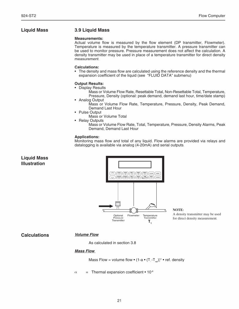
21
924-ST2 Flow Computer
3.9 Liquid Mass
Measurements:Actual volume fl ow is measured by the fl ow element (DP transmitter, Flowmeter). Temperature is measured by the temperature transmitter. A pressure transmitter can be used to monitor pressure. Pressure measurement does not affect the calculation. A density transmitter may be used in place of a temperature transmitter for direct density measurement.
Calculations:• The density and mass fl ow are calculated using the reference density and the thermal
expansion coeffi cient of the liquid (see "FLUID DATA" submenu)
Output Results:• Display Results Mass or Volume Flow Rate, Resettable Total, Non-Resettable Total, Temperature,
Pressure, Density (optional: peak demand, demand last hour, time/date stamp)• Analog Output Mass or Volume Flow Rate, Temperature, Pressure, Density, Peak Demand,
Demand Last Hour• Pulse Output Mass or Volume Total• Relay Outputs Mass or Volume Flow Rate, Total, Temperature, Pressure, Density Alarms, Peak
Demand, Demand Last Hour
Applications:Monitoring mass fl ow and total of any liquid. Flow alarms are provided via relays and datalogging is available via analog (4-20mA) and serial outputs.
Liquid Mass
Liquid MassIllustration
Volume Flow
As calculated in section 3.8
Mass Flow
Mass Flow = volume fl ow • (1-a • (T1-Tref))2 • ref. density
α = Thermal expansion coeffi cient • 10-6
Calculations
NOTE:A density transmitter may be used for direct density measurement.
Flowmeter Temperaturer Temperaturer TTransmitter
PRINT5
0 –
TIME
CLEAR
•
MENU
ENTERHELP
TEMP4
PRE 13
RATE2
TOTAL1
GRAND6
SCROLL7
PRE 28
DENS9
OptionalPressure
Transmitter T1
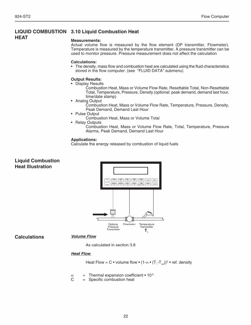
22
924-ST2 Flow Computer
3.10 Liquid Combustion Heat
Measurements:Actual volume fl ow is measured by the fl ow element (DP transmitter, Flowmeter). Temperature is measured by the temperature transmitter. A pressure transmitter can be used to monitor pressure. Pressure measurement does not affect the calculation.
Calculations:• The density, mass fl ow and combustion heat are calculated using the fl uid characteristics
stored in the fl ow computer. (see "FLUID DATA" submenu)
Output Results:• Display Results Combustion Heat, Mass or Volume Flow Rate, Resettable Total, Non-Resettable
Total, Temperature, Pressure, Density (optional: peak demand, demand last hour, time/date stamp)
• Analog Output Combustion Heat, Mass or Volume Flow Rate, Temperature, Pressure, Density,
Peak Demand, Demand Last Hour• Pulse Output Combustion Heat, Mass or Volume Total• Relay Outputs Combustion Heat, Mass or Volume Flow Rate, Total, Temperature, Pressure
Alarms, Peak Demand, Demand Last Hour
Applications:Calculate the energy released by combustion of liquid fuels
LIQUID COMBUSTION HEAT
Liquid Combustion Heat Illustration
Volume Flow
As calculated in section 3.8
Heat Flow
Heat Flow = C • volume fl ow • (1-α • (T1-Tref))2 • ref. density
α = Thermal expansion coeffi cient • 10-6
C = Specifi c combustion heat
Calculations
Flowmeter Temperaturer Temperaturer TTransmitter
PRINT5
0 –
TIME
CLEAR
•
MENU
ENTERHELP
TEMP4
PRE 13
RATE2
TOTAL1
GRAND6
SCROLL7
PRE 28
DENS9
OptionalPressure
Transmitter T1
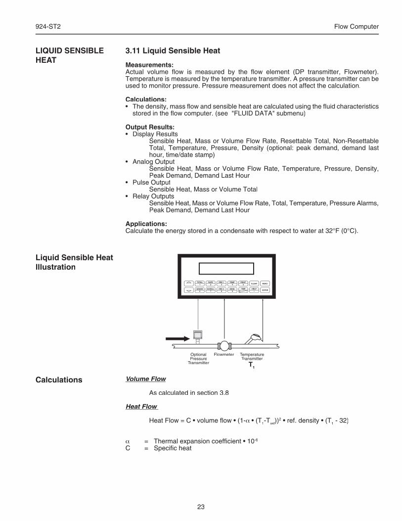
23
924-ST2 Flow Computer
3.11 Liquid Sensible Heat
Measurements:Actual volume fl ow is measured by the fl ow element (DP transmitter, Flowmeter). Temperature is measured by the temperature transmitter. A pressure transmitter can be used to monitor pressure. Pressure measurement does not affect the calculation.
Calculations:• The density, mass fl ow and sensible heat are calculated using the fl uid characteristics
stored in the fl ow computer. (see "FLUID DATA" submenu)
Output Results:• Display Results Sensible Heat, Mass or Volume Flow Rate, Resettable Total, Non-Resettable
Total, Temperature, Pressure, Density (optional: peak demand, demand last hour, time/date stamp)
• Analog Output Sensible Heat, Mass or Volume Flow Rate, Temperature, Pressure, Density,
Peak Demand, Demand Last Hour• Pulse Output Sensible Heat, Mass or Volume Total• Relay Outputs Sensible Heat, Mass or Volume Flow Rate, Total, Temperature, Pressure Alarms,
Peak Demand, Demand Last Hour
Applications:Calculate the energy stored in a condensate with respect to water at 32°F (0°C).
LIQUID SENSIBLE HEAT
Liquid Sensible Heat Illustration
Volume Flow
As calculated in section 3.8
Heat Flow
Heat Flow = C • volume fl ow • (1-α • (T1-Tref))2 • ref. density • (T1 - 32)
α = Thermal expansion coeffi cient • 10-6
C = Specifi c heat
Calculations
Flowmeter Temperaturer Temperaturer TTransmitter
PRINT5
0 –
TIME
CLEAR
•
MENU
ENTERHELP
TEMP4
PRE 13
RATE2
TOTAL1
GRAND6
SCROLL7
PRE 28
DENS9
OptionalPressure
Transmitter T1
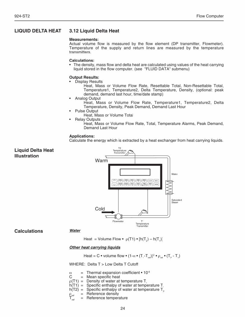
24
924-ST2 Flow Computer
3.12 Liquid Delta Heat
Measurements:Actual volume fl ow is measured by the fl ow element (DP transmitter, Flowmeter). Temperature of the supply and return lines are measured by the temperature transmitters.
Calculations:• The density, mass fl ow and delta heat are calculated using values of the heat carrying
liquid stored in the fl ow computer. (see "FLUID DATA" submenu)
Output Results:• Display Results Heat, Mass or Volume Flow Rate, Resettable Total, Non-Resettable Total,
Temperature1, Temperature2, Delta Temperature, Density, (optional: peak demand, demand last hour, time/date stamp)
• Analog Output Heat, Mass or Volume Flow Rate, Temperature1, Temperature2, Delta
Temperature, Density, Peak Demand, Demand Last Hour• Pulse Output Heat, Mass or Volume Total• Relay Outputs Heat, Mass or Volume Flow Rate, Total, Temperature Alarms, Peak Demand,
Demand Last Hour
Applications:Calculate the energy which is extracted by a heat exchanger from heat carrying liquids.
LIQUID DELTA HEAT
Liquid Delta Heat Illustration
Water
Heat = Volume Flow • ρ(T1) • [h(T2) – h(T1)]
Other heat carrying liquidsOther heat carrying liquids
Heat = C • volume fl ow • (1-α • (T1-Tref))2 • ρref • (T2 - T1)
WHERE: Delta T > Low Delta T Cutoff
α = Thermal expansion coeffi cient • 10-6
C = Mean specifi c heatρ(T1) = Density of water at temperature T1h(T1) = Specifi c enthalpy of water at temperature T
1h(T1) = Specifi c enthalpy of water at temperature T
1
1h(T2) = Specifi c enthalpy of water at temperature T2ρref = Reference densityT
refT
ref
ref = Reference temperature
Calculations
Flowmeter
T2TemperatureTemperatureTTransmitter
PRINT5
0 –
TIME
CLEAR
•
MENU
ENTERHELP
TEMP4
PRE 13
RATE2
TOTAL1
GRAND6
SCROLL7
PRE 28
DENS9
T1TemperatureTemperatureTTransmitter
Water
SaturatedSteam
WarmWarm
ColdCold
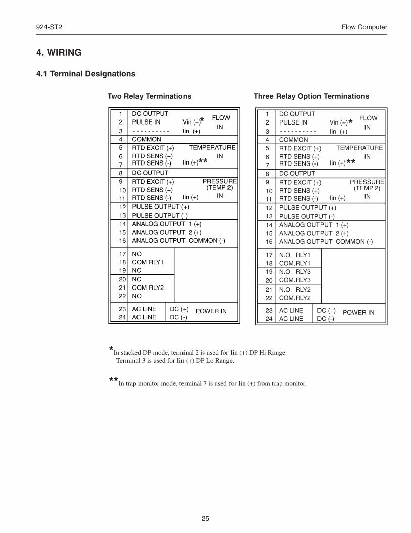
25
924-ST2 Flow Computer
4. WIRING
4.1 Terminal Designations
*In stacked DP mode, terminal 2 is used for Iin (+) DP Hi Range. Terminal 3 is used for Iin (+) DP Lo Range.
** In trap monitor mode, terminal 7 is used for Iin (+) from trap monitor.
Two Relay Terminations Three Relay Option Terminations
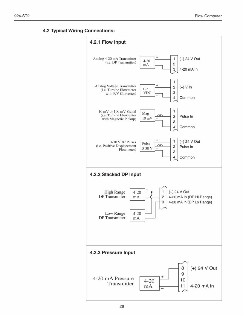
26
924-ST2 Flow Computer
4.2 Typical Wiring Connections:
4.2.1 Flow Input
4.2.2 Stacked DP Input
+
–
+
–
Mag10 mV –
Pulse3-30 V –
+
Analog 4-20 mA TAnalog 4-20 mA TAnalog 4-20 mA ransmitter Transmitter T(i.e. DP T(i.e. DP T(i.e. DP ransmitter) Transmitter) T
Analog Voltage Voltage V TransmitterTransmitterT(i.e. Turbine FlowmeterTurbine FlowmeterT
with F/V Converter)
10 mV or 100 mV Signal(i.e. Turbine FlowmeterTurbine FlowmeterTwith Magnetic Pickup)
3-30 VDC Pulses(i.e. Positive Displacement
Flowmeter)
0-5VDC
4-20mA
1234
1234
123
(+) 24 V Out
4-20 mA In
(+) V In
Common
Pulse In
Common
(+) 24 V OutPulse In
Common
1234
+
–
High RangeDP Transmitter
4-20mA
+
–
Low RangeDP Transmitter
4-20mA
(+) 24 V Out4-20 mA In (DP Hi Range)4-20 mA In (DP Lo Range)
123
4.2.3 Pressure Input
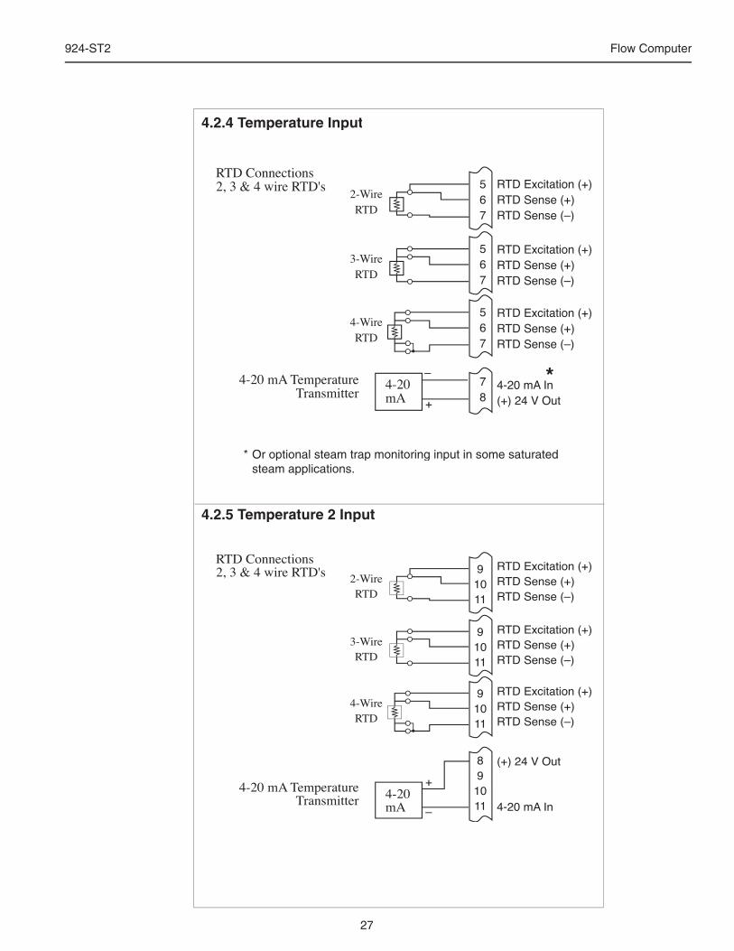
27
924-ST2 Flow Computer
4.2.4 Temperature Input
4.2.5 Temperature 2 Input
*
* Or optional steam trap monitoring input in some saturated steam applications.
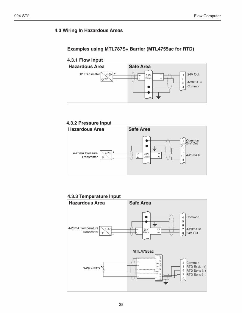
28
924-ST2 Flow Computer
Hazardous Area Safe Area
4-20mA Temperature Transmitter
4.3.3 Temperature Input
Common
4-20mA In24V Out
CommonRTD Excit (+)RTD Sens (+)RTD Sens (–)
3-Wire RTD
MTL4755ac
Hazardous Area Safe Area4.3.2 Pressure Input
4.3 Wiring In Hazardous Areas
Hazardous Area Safe Area
DP Transmitter 24V Out
4-20mA InCommon
4.3.1 Flow Input
Examples using MTL787S+ Barrier (MTL4755ac for RTD)
4-20mA Pressure Transmitter
Common24V Out
4-20mA In
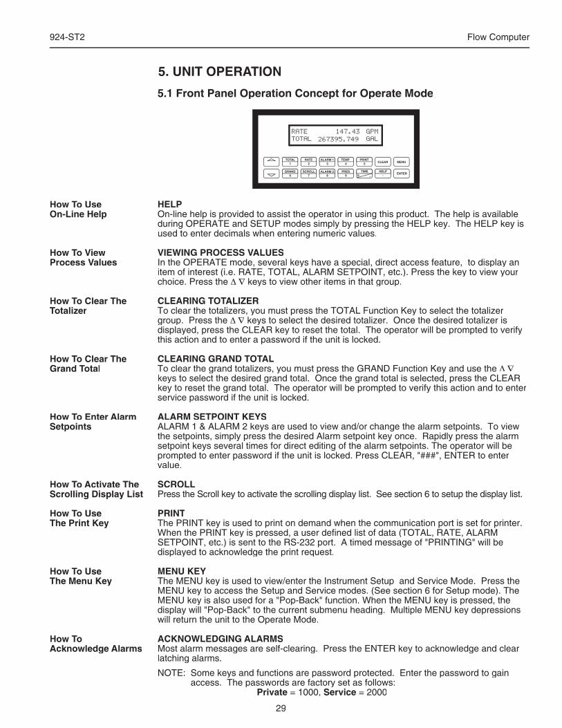
29
924-ST2 Flow Computer
5. UNIT OPERATION
5.1 Front Panel Operation Concept for Operate Mode
HELPOn-line help is provided to assist the operator in using this product. The help is available during OPERATE and SETUP modes simply by pressing the HELP key. The HELP key is used to enter decimals when entering numeric values.
VIEWING PROCESS VALUESIn the OPERATE mode, several keys have a special, direct access feature, to display an item of interest (i.e. RATE, TOTAL, ALARM SETPOINT, etc.). Press the key to view your choice. Press the Δ ∇ keys to view other items in that group.
CLEARING TOTALIZERTo clear the totalizers, you must press the TOTAL Function Key to select the totalizer group. Press the Δ ∇ keys to select the desired totalizer. Once the desired totalizer is displayed, press the CLEAR key to reset the total. The operator will be prompted to verify this action and to enter a password if the unit is locked.
CLEARING GRAND TOTALTo clear the grand totalizers, you must press the GRAND Function Key and use the Δ ∇keys to select the desired grand total. Once the grand total is selected, press the CLEAR key to reset the grand total. The operator will be prompted to verify this action and to enter service password if the unit is locked.
ALARM SETPOINT KEYSALARM 1 & ALARM 2 keys are used to view and/or change the alarm setpoints. To view the setpoints, simply press the desired Alarm setpoint key once. Rapidly press the alarm setpoint keys several times for direct editing of the alarm setpoints. The operator will be prompted to enter password if the unit is locked. Press CLEAR, "###", ENTER to enter value.
SCROLLPress the Scroll key to activate the scrolling display list. See section 6 to setup the display list.
PRINTThe PRINT key is used to print on demand when the communication port is set for printer. When the PRINT key is pressed, a user defi ned list of data (TOTAL, RATE, ALARM SETPOINT, etc.) is sent to the RS-232 port. A timed message of "PRINTING" will be displayed to acknowledge the print request.
MENU KEYThe MENU key is used to view/enter the Instrument Setup and Service Mode. Press the MENU key to access the Setup and Service modes. (See section 6 for Setup mode). The MENU key is also used for a "Pop-Back" function. When the MENU key is pressed, the display will "Pop-Back" to the current submenu heading. Multiple MENU key depressions will return the unit to the Operate Mode.
ACKNOWLEDGING ALARMSMost alarm messages are self-clearing. Press the ENTER key to acknowledge and clear latching alarms.
NOTE: Some keys and functions are password protected. Enter the password to gain access. The passwords are factory set as follows:
Private = 1000, Service = 2000
How To Use On-Line Help
How To ViewProcess Values
How To Clear The Totalizer
How To Clear The Grand Total
How To Enter Alarm Setpoints
How To Activate TheScrolling Display List
How To Use The Print Key
How To Use The Menu Key
How To Acknowledge Alarms
30
924-ST2 Flow Computer
5.2 General Operation
This instrument is used primarily to monitor fl owrate and accumulated total. The inputs can be software confi gured for a variety of fl owmeter, temperature and pressure sensors. The standard output types include: Pulse, Relay, Analog and RS-232 The unit can display the fl owrate, total and process variables. RS-485 is an available option for a second communication channel.
5.3 Password Protection
After an Private and/or Service Code is entered in the "System Parameters" Submenu Group. (see section 6.3, Private Code and Service Code sub-menus), the unit will be locked. The unit will prompt the user for the password when trying to perform the following functions:
Clear TotalsClear Grand Totals (service code required)Edit a Setup Menu ItemEdit Alarm Setpoints (ALARM 1 & ALARM 2 Keys)
The Service Code should be reserved for service technicians. The Service Code will allow access to restricted areas of the Service and Test menus. Changes in these areas may result in lost calibration information.
5.4 Relay Operation
Two relay alarm outputs are standard. The relays may also be used for pulse outputs. The relays can be assigned to trip according to various rate, total, temperature or pressure readings. The relays can be programmed for low/high alarms, latch or unlatch, or as relay pulse outputs.ALARM SETPOINT 1 (RLY1) and ALARM SETPOINT 2 (RLY2) are easily accessible by pressing the ALARM 1 or ALARM 2 key on the front panel.
5.5 Pulse Output
The isolated pulse output is menu assignable to any of the available totals. The pulse output duration and scaling can be set by the user. The pulse output is ideal for connecting to remote totalizers or other devices such as a PLC. See section 1.2 for electrical specifi cations.
5.6 Analog Outputs
The analog outputs are menu assignable to correspond to any of the process parameters. The outputs are menu selectable for 0-20 mA or 4-20 mA. The analog outputs are ideal for "trend" tracking using strip chart recorders or other devices.
5.7 Function Keys; Display Grouping
TOTAL Press the keys to view HEAT TOTAL, MASS TOTAL, CORRECTED
VOLUME TOTAL, VOLUME TOTAL
GRAND TOTAL Press the keys to view GRAND HEAT, GRAND MASS, GRAND
CORRECTED VOLUME, GRAND VOLUME
RATE Press the keys to view HEAT, MASS , CORRECTED VOLUME,
VOLUME, PEAK DEMAND, DEMAND LAST HOUR
TEMPERATURE Press the keys to view TEMPERATURE 1, TEMPERATURE 2, DELTA
TEMPERATURE, DENSITY
PRESSURE Press the keys to view PRESSURE, DIFFERENTIAL PRESSURE, , Y1,
SPECIFIC ENTHALPY
TIME Press the keys to view TIME/DATE, PEAK TIME/DATE, ACCUMULATIVE Press the keys to view TIME/DATE, PEAK TIME/DATE, ACCUMULATIVE Press the keys to view
POWER LOSS TIME, TIME OF LAST POWER OUTAGE, TIME POWER WAS
LAST RESTORED
GeneralOperation
Password Protection
Relay Operation
Pulse Output
Analog Outputs
Function KeysDisplay Grouping
31
924-ST2 Flow Computer
5.8 RS-232 Serial Port OperationThe RS-232 serial port can be used for programming (using the Setup Disk) or for communicating to printers and computers in the Operating Mode (Run Mode). Enhanced uses include remote metering by modem or two way pager.
5.8.1 PC Communications:The Setup Disk also allows the user to query the unit for operating status such as Flow Rate, Flow Total, Temperature, Pressure, Alarm Setpoints, etc.In this mode of operation the RS232 port is assumed connected to a computer. The 924-ST2 will act as a slave and answer requests from the PC. See the Universal Protocol Users Manual for a complete listing of the commands set supported. A DDE/OPC Server is also available for use in exchanging information with DDE Clients such as Spread Sheets, Database Programs, and HMI software.
5.8.2 Operation of RS-232 Serial Port with Printers:Transaction PrintingTransaction PrintingFor transaction printing, the user defi nes the items to be included in the printed document (see section 6.13 COMMUNICATION, Print List). The transaction document can be initiated by pressing the PRINT key.
Data LoggingData LoggingThe user can select when (time of day) or how often (print interval) the data log is to be made (see section 6.13 COMMUNICATION, Print Initiate). Information will be stored to the datalogger and optionally output to the RS-232 port.
System Setup and Maintenance ReportSystem Setup and Maintenance ReportThe system setup and maintenance report lists all of the instrument setup parameters and usage for the current instrument confi guration. The audit trail information and a status report is also printed. This report is initiated in the Service and Analysis Group (see section 6.15 SERVICE & ANALYSIS, Print System Setup).
5.8.3 Operation of RS-232 Serial Port with Modems and PagersModemIn this mode of operation the RS232 port is assumed to be connected to a MPP2400N or similar telephone modem. The 924-ST2 is responsible for communicating to a remote computer through the modem to perform such actions as:Answer incoming calls, process requests for information or action items or data log contents or change setup parameters, call out daily readings to designed phone number, call out to designated phone number in the case of a designated exception or malfunction in the unit, terminating telephone calls if a connection is lost.
Two Way PagingTwo Way PagingIn this mode of operation the RS232 port is assumed to be connected to a TWP Two Way Pager Transceiver. The 924-ST2 is responsible for communicating to the pager to perform such actions as: Look for and process requests for information or change setup parameters, call out daily readings to designed pager/email address, call out to designated pager/email address in the case of a designated exception or malfunction in the unit.
5.9 RS-485 Serial Port OperationThe RS-485 serial port is intended to permit operation of the fl ow computer in a RS-485 network. Access is limited to reading process variables, totalizers, error logs and to executing action routines such as clearing totalizers, alarms, and changing setpoints.
5.10 Pause Computations PromptThe user will be prompted with a "Pause Computations" message when making signifi cant setup changes to the instrument. Pausing computations is necessary to make any signifi cant changes. With computations paused, all outputs assume a safe state equal to that of an unpowered unit. Computations resume when exiting the setup menu.
RS-232 Serial PortOperation
PC Communications
RS-232 Serial Port Operation of RS-232 Serial Port with Printers
Operation of RS-232 Serial Port with Modems and Pagers
RS-485 Serial Port Operation
Pause ComputationsPrompt
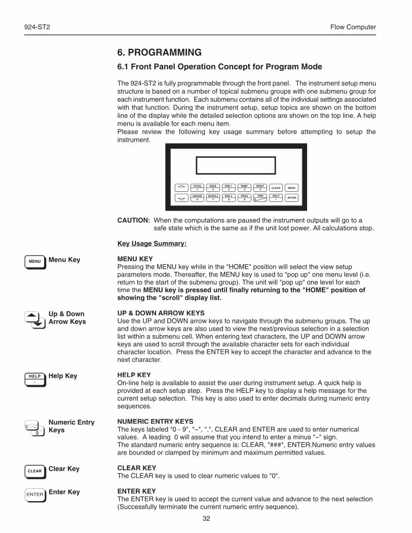
32
924-ST2 Flow Computer
6. PROGRAMMING6.1 Front Panel Operation Concept for Program Mode
The 924-ST2 is fully programmable through the front panel. The instrument setup menu structure is based on a number of topical submenu groups with one submenu group for each instrument function. Each submenu contains all of the individual settings associated with that function. During the instrument setup, setup topics are shown on the bottom line of the display while the detailed selection options are shown on the top line. A help menu is available for each menu item.Please review the following key usage summary before attempting to setup the instrument.
CAUTION: When the computations are paused the instrument outputs will go to a safe state which is the same as if the unit lost power. All calculations stop.
Key Usage Summary:Key Usage Summary:
MENU KEYPressing the MENU key while in the "HOME" position will select the view setup parameters mode. Thereafter, the MENU key is used to "pop up" one menu level (i.e. return to the start of the submenu group). The unit will "pop up" one level for each time the MENU key is pressed until fi nally returning to the "HOME" position of showing the "scroll" display list.
UP & DOWN ARROW KEYSUse the UP and DOWN arrow keys to navigate through the submenu groups. The up and down arrow keys are also used to view the next/previous selection in a selection list within a submenu cell. When entering text characters, the UP and DOWN arrow keys are used to scroll through the available character sets for each individual character location. Press the ENTER key to accept the character and advance to the next character.
HELP KEYOn-line help is available to assist the user during instrument setup. A quick help is provided at each setup step. Press the HELP key to display a help message for the current setup selection. This key is also used to enter decimals during numeric entry sequences.
NUMERIC ENTRY KEYSThe keys labeled "0 - 9", "–", ".", CLEAR and ENTER are used to enter numerical values. A leading 0 will assume that you intend to enter a minus "–" sign.The standard numeric entry sequence is: CLEAR, "###", ENTER.Numeric entry values are bounded or clamped by minimum and maximum permitted values.
CLEAR KEYThe CLEAR key is used to clear numeric values to "0".
ENTER KEYThe ENTER key is used to accept the current value and advance to the next selection (Successfully terminate the current numeric entry sequence).
PRINT5
0 –
TIME
CLEAR
•
MENU
ENTERHELP
TEMP4
PRE 13
RATE2
TOTAL1
GRAND6
SCROLL7
PRE 28
PRES9
Menu Key
Up & DownArrow Keys
Help Key
Numeric EntryKeys
Clear Key
Enter Key
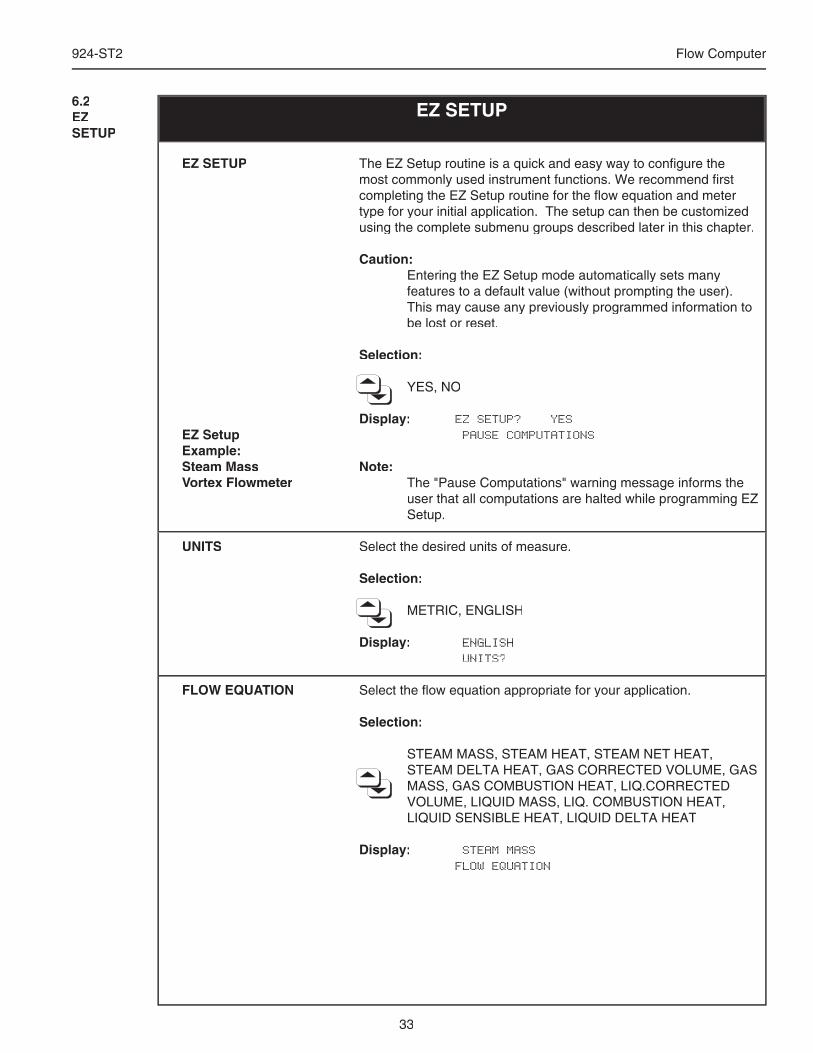
33
924-ST2 Flow Computer
EZ SETUP
EZ SETUP
EZ Setup Example:Steam MassVortex Flowmeter
UNITS
FLOW EQUATION
The EZ Setup routine is a quick and easy way to confi gure the most commonly used instrument functions. We recommend fi rst completing the EZ Setup routine for the fl ow equation and meter type for your initial application. The setup can then be customized using the complete submenu groups described later in this chapter.
Caution: Entering the EZ Setup mode automatically sets many
features to a default value (without prompting the user). This may cause any previously programmed information to be lost or reset.
Selection:
YES, NO
Display: EZ SETUP? YES PAUSE COMPUTATIONS
Note: The "Pause Computations" warning message informs the
user that all computations are halted while programming EZ Setup.
Select the desired units of measure.
Selection:
METRIC, ENGLISH
Display: ENGLISH UNITS?
Select the fl ow equation appropriate for your application.
Selection:
STEAM MASS, STEAM HEAT, STEAM NET HEAT, STEAM DELTA HEAT, GAS CORRECTED VOLUME, GAS MASS, GAS COMBUSTION HEAT, LIQ.CORRECTED VOLUME, LIQUID MASS, LIQ. COMBUSTION HEAT, LIQUID SENSIBLE HEAT, LIQUID DELTA HEAT
Display: STEAM MASS FLOW EQUATION
6.2EZSETUP
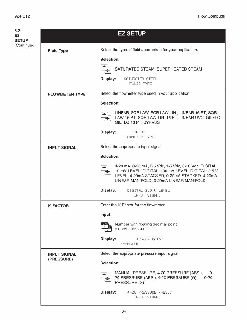
34
924-ST2 Flow Computer
Select the type of fl uid appropriate for your application.
Selection: SATURATED STEAM, SUPERHEATED STEAM
Display: SATURATED STEAM FLUID TYPE
Select the fl owmeter type used in your application.
Selection:
LINEAR, SQR LAW, SQR LAW-LIN., LINEAR 16 PT, SQR LAW 16 PT, SQR LAW-LIN. 16 PT, LINEAR UVC, GILFLO, GILFLO 16 PT, BYPASS
Display: LINEAR FLOWMETER TYPE
Select the appropriate input signal.
Selection:
4-20 mA, 0-20 mA, 0-5 Vdc, 1-5 Vdc, 0-10 Vdc, DIGITAL: 10 mV LEVEL, DIGITAL: 100 mV LEVEL, DIGITAL: 2.5 V LEVEL, 4-20mA STACKED, 0-20mA STACKED, 4-20mA LINEAR MANIFOLD, 0-20mA LINEAR MANIFOLD
Display: DIGITAL 2.5 V LEVEL INPUT SIGNAL
Enter the K-Factor for the fl owmeter.
Input:
Number with fl oating decimal point: 0.0001...999999
Display: 123.67 P/ft3 K-FACTOR
Select the appropriate pressure input signal.
Selection:
MANUAL PRESSURE, 4-20 PRESSURE (ABS.), 0-20 PRESSURE (ABS.), 4-20 PRESSURE (G), 0-20 PRESSURE (G)
Display: 4-20 PRESSURE (ABS.) INPUT SIGNAL
EZ SETUP
Fluid Type
FLOWMETER TYPE
INPUT SIGNAL
K-FACTOR
INPUT SIGNAL(PRESSURE)
6.2EZSETUP(Continued)
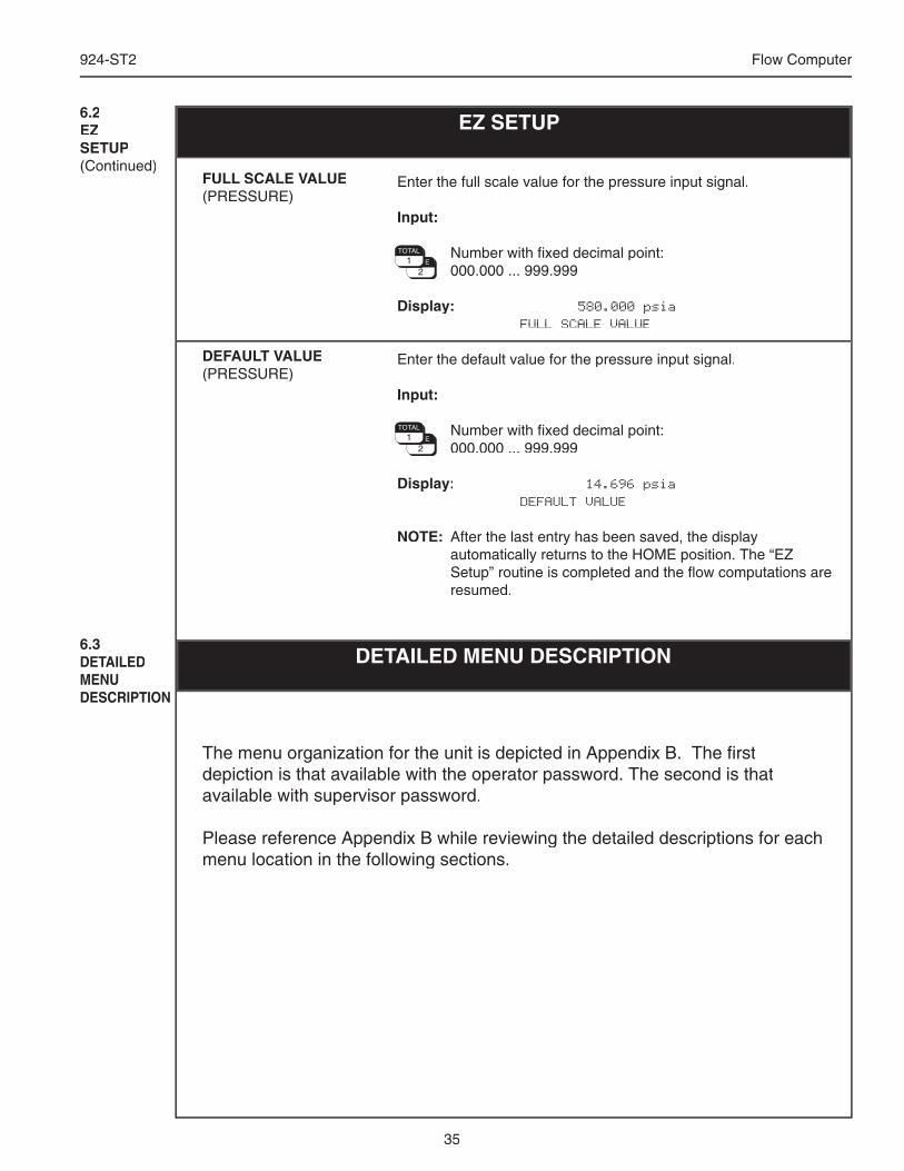
35
924-ST2 Flow Computer
Enter the full scale value for the pressure input signal.
Input:
Number with fi xed decimal point: 000.000 ... 999.999
Display: 580.000 psia FULL SCALE VALUE
Enter the default value for the pressure input signal.
Input:
Number with fi xed decimal point: 000.000 ... 999.999
Display: 14.696 psia DEFAULT VALUE
NOTE: After the last entry has been saved, the display automatically returns to the HOME position. The “EZ Setup” routine is completed and the fl ow computations are resumed.
EZ SETUP
FULL SCALE VALUE(PRESSURE)
DEFAULT VALUE(PRESSURE)
6.2EZSETUP(Continued)
6.3DETAILEDMENU DESCRIPTION
DETAILED MENU DESCRIPTION
The menu organization for the unit is depicted in Appendix B. The fi rst depiction is that available with the operator password. The second is that available with supervisor password.
Please reference Appendix B while reviewing the detailed descriptions for each menu location in the following sections.
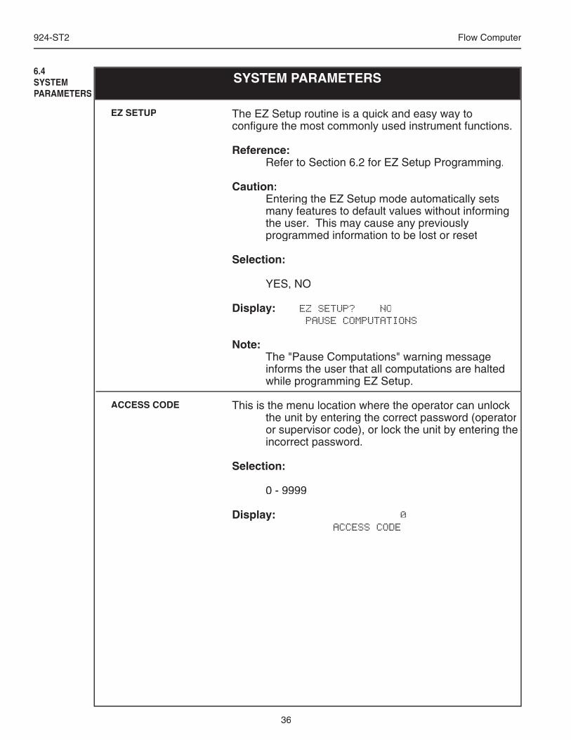
36
924-ST2 Flow Computer
6.4SYSTEMPARAMETERS
SYSTEM PARAMETERS
The EZ Setup routine is a quick and easy way to confi gure the most commonly used instrument functions.
Reference: Refer to Section 6.2 for EZ Setup Programming.
Caution: Entering the EZ Setup mode automatically sets
many features to default values without informing the user. This may cause any previously programmed information to be lost or reset
Selection:
YES, NO
Display: EZ SETUP? NO PAUSE COMPUTATIONS
Note: The "Pause Computations" warning message
informs the user that all computations are halted while programming EZ Setup.
This is the menu location where the operator can unlock the unit by entering the correct password (operator or supervisor code), or lock the unit by entering the incorrect password.
Selection:
0 - 9999
Display: 0 ACCESS CODE
EZ SETUP
ACCESS CODE
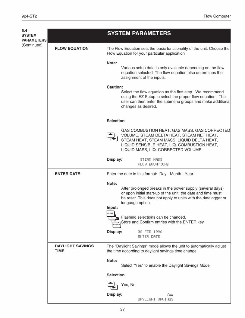
37
924-ST2 Flow Computer
The Flow Equation sets the basic functionality of the unit. Choose the Flow Equation for your particular application.
Note: Various setup data is only available depending on the fl ow
equation selected. The fl ow equation also determines the assignment of the inputs.
Caution: Select the fl ow equation as the fi rst step. We recommend
using the EZ Setup to select the proper fl ow equation. The user can then enter the submenu groups and make additional changes as desired.
Selection:
GAS COMBUSTION HEAT, GAS MASS, GAS CORRECTED VOLUME, STEAM DELTA HEAT, STEAM NET HEAT, STEAM HEAT, STEAM MASS, LIQUID DELTA HEAT, LIQUID SENSIBLE HEAT, LIQ. COMBUSTION HEAT, LIQUID MASS, LIQ. CORRECTED VOLUME.
Display: STEAM MASS FLOW EQUATIONS
Enter the date in this format: Day - Month - Year.
Note: After prolonged breaks in the power supply (several days)
or upon initial start-up of the unit, the date and time must be reset. This does not apply to units with the datalogger or language option.
Input:
Flashing selections can be changed. Store and Confi rm entries with the ENTER key
Display: 08 FEB 1996 ENTER DATE
The "Daylight Savings" mode allows the unit to automatically adjust the time according to daylight savings time change
Note: Select "Yes" to enable the Daylight Savings Mode
Selection:
Yes, No
Display: Yes DAYLIGHT SAVINGS
SYSTEM PARAMETERS6.4SYSTEMPARAMETERS(Continued)
FLOW EQUATION
ENTER DATE
DAYLIGHT SAVINGS TIME
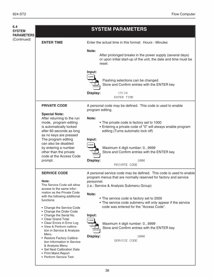
38
924-ST2 Flow Computer
SYSTEM PARAMETERS6.4SYSTEMPARAMETERS(Continued)
ENTER TIME
PRIVATE CODE
Special Note:After returning to the run mode, program editing is automatically locked after 60 seconds as long as no keys are pressed The program editing can also be disabled by entering a number other than the private code at the Access Code prompt.
SERVICE CODE
Note:The Service Code will allow access to the same infor-mation as the Private Code with the following additional functions:
• Change the Service Code• Change the Order Code• Change the Serial No.• Clear Grand Total• Clear Errors in Error Log• View & Perform calibra-
tion in Service & Analysis Menu
• Restore Factory Calibra-tion Information in Service & Analysis Menu
• Set Next Calibration Date• Print Maint.Report• Perform Service Test
Enter the actual time in this format: Hours - Minutes
Note: After prolonged breaks in the power supply (several days)
or upon initial start-up of the unit, the date and time must be reset.
Input:
Flashing selections can be changed. Store and Confi rm entries with the ENTER key
Display: 13:24 ENTER TIME
A personal code may be defi ned. This code is used to enable program editing.
Note: • The private code is factory set to 1000 • Entering a private code of "0" will always enable program
editing (Turns automatic lock off)
Input:
Maximum 4 digit number: 0...9999 Store and Confi rm entries with the ENTER key
Display: 1000 PRIVATE CODE
A personal service code may be defi ned. This code is used to enable program menus that are normally reserved for factory and service personnel. (i.e.: Service & Analysis Submenu Group)
Note: • The service code is factory set to 2000 • The service code submenu will only appear if the service
code was entered for the "Access Code".
Input:
Maximum 4 digit number: 0...9999 Store and Confi rm entries with the ENTER key
Display: 2000 SERVICE CODE
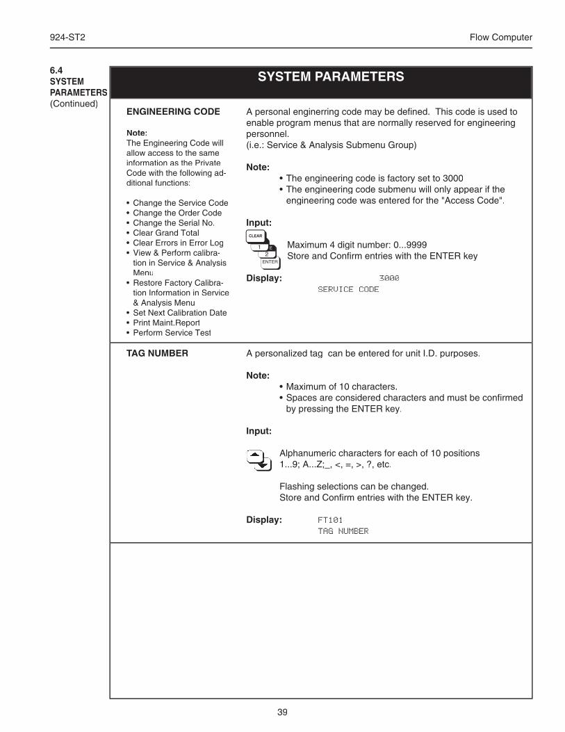
39
924-ST2 Flow Computer
SYSTEM PARAMETERS6.4SYSTEMPARAMETERS(Continued)
A personalized tag can be entered for unit I.D. purposes.
Note: • Maximum of 10 characters. • Spaces are considered characters and must be confi rmed
by pressing the ENTER key.
Input:
Alphanumeric characters for each of 10 positions Alphanumeric characters for each of 10 positions Alphanumeric characters for each of 10 positions Alphanumeric characters for each of 10 positions Alphanumeric characters for each of 10 positions Alphanumeric characters for each of 10 positions Alphanumeric characters for each of 10 positions Alphanumeric characters for each of 10 positions Alphanumeric characters for each of 10 positions 1...9; A...Z;_, <, =, >, ?, etc. 1...9; A...Z;_, <, =, >, ?, etc. 1...9; A...Z;_, <, =, >, ?, etc. 1...9; A...Z;_, <, =, >, ?, etc. 1...9; A...Z;_, <, =, >, ?, etc. 1...9; A...Z;_, <, =, >, ?, etc. 1...9; A...Z;_, <, =, >, ?, etc. 1...9; A...Z;_, <, =, >, ?, etc. 1...9; A...Z;_, <, =, >, ?, etc. 1...9; A...Z;_, <, =, >, ?, etc. 1...9; A...Z;_, <, =, >, ?, etc.
Flashing selections can be changed. Store and Confi rm entries with the ENTER key.
Display: FT101 TAG NUMBER
TAG NUMBER
ENGINEERING CODE
Note:The Engineering Code will allow access to the same information as the Private Code with the following ad-ditional functions:
• Change the Service Code• Change the Order Code• Change the Serial No.• Clear Grand Total• Clear Errors in Error Log• View & Perform calibra-
tion in Service & Analysis Menu
• Restore Factory Calibra-tion Information in Service & Analysis Menu
• Set Next Calibration Date• Print Maint.Report• Perform Service Test
A personal enginerring code may be defi ned. This code is used to enable program menus that are normally reserved for engineering personnel. (i.e.: Service & Analysis Submenu Group)
Note: • The engineering code is factory set to 3000 • The engineering code submenu will only appear if the
engineering code was entered for the "Access Code".
Input:
Maximum 4 digit number: 0...9999 Store and Confi rm entries with the ENTER key
Display: 3000 SERVICE CODE
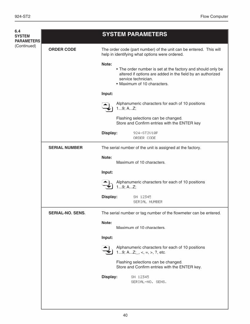
40
924-ST2 Flow Computer
The order code (part number) of the unit can be entered. This will help in identifying what options were ordered.
Note: • The order number is set at the factory and should only be
altered if options are added in the fi eld by an authorized service technician.
• Maximum of 10 characters.
Input:
Alphanumeric characters for each of 10 positions Alphanumeric characters for each of 10 positions Alphanumeric characters for each of 10 positions Alphanumeric characters for each of 10 positions Alphanumeric characters for each of 10 positions Alphanumeric characters for each of 10 positions Alphanumeric characters for each of 10 positions 1...9; A...Z; 1...9; A...Z; 1...9; A...Z; 1...9; A...Z; 1...9; A...Z; 1...9; A...Z; 1...9; A...Z; 1...9; A...Z; 1...9; A...Z; 1...9; A...Z; 1...9; A...Z;
Flashing selections can be changed. Store and Confi rm entries with the ENTER key
Display: 924-ST2V10P ORDER CODE
The serial number of the unit is assigned at the factory.
Note: Maximum of 10 characters.
Input:
Alphanumeric characters for each of 10 positions Alphanumeric characters for each of 10 positions Alphanumeric characters for each of 10 positions Alphanumeric characters for each of 10 positions Alphanumeric characters for each of 10 positions Alphanumeric characters for each of 10 positions Alphanumeric characters for each of 10 positions Alphanumeric characters for each of 10 positions Alphanumeric characters for each of 10 positions Alphanumeric characters for each of 10 positions Alphanumeric characters for each of 10 positions 1...9; A...Z; 1...9; A...Z; 1...9; A...Z; 1...9; A...Z; 1...9; A...Z; 1...9; A...Z; 1...9; A...Z; 1...9; A...Z; 1...9; A...Z;
Display: SN 12345 SERIAL NUMBER
ORDER CODE
SERIAL NUMBER
SYSTEM PARAMETERS6.4SYSTEMPARAMETERS(Continued)
SERIAL-NO. SENS. The serial number or tag number of the fl owmeter can be entered.
Note: Maximum of 10 characters.
Input:
Alphanumeric characters for each of 10 positions Alphanumeric characters for each of 10 positions Alphanumeric characters for each of 10 positions Alphanumeric characters for each of 10 positions Alphanumeric characters for each of 10 positions Alphanumeric characters for each of 10 positions Alphanumeric characters for each of 10 positions Alphanumeric characters for each of 10 positions Alphanumeric characters for each of 10 positions Alphanumeric characters for each of 10 positions Alphanumeric characters for each of 10 positions 1...9; A...Z;_, <, =, >, ?, etc. 1...9; A...Z;_, <, =, >, ?, etc. 1...9; A...Z;_, <, =, >, ?, etc. 1...9; A...Z;_, <, =, >, ?, etc. 1...9; A...Z;_, <, =, >, ?, etc. 1...9; A...Z;_, <, =, >, ?, etc. 1...9; A...Z;_, <, =, >, ?, etc. 1...9; A...Z;_, <, =, >, ?, etc. 1...9; A...Z;_, <, =, >, ?, etc. 1...9; A...Z;_, <, =, >, ?, etc.
Flashing selections can be changed. Store and Confi rm entries with the ENTER key.
Display: SN 12345 SERIAL-NO. SENS.
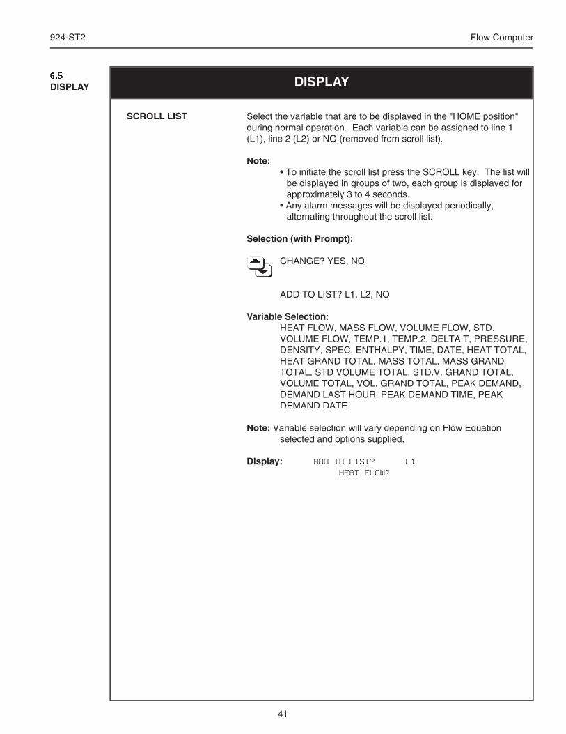
41
924-ST2 Flow Computer
DISPLAY6.5DISPLAY
Select the variable that are to be displayed in the "HOME position" during normal operation. Each variable can be assigned to line 1 (L1), line 2 (L2) or NO (removed from scroll list).
Note: • To initiate the scroll list press the SCROLL key. The list will
be displayed in groups of two, each group is displayed for approximately 3 to 4 seconds.
• Any alarm messages will be displayed periodically, alternating throughout the scroll list.
Selection (with Prompt):
CHANGE? YES, NO CHANGE? YES, NO CHANGE? YES, NO CHANGE? YES, NO CHANGE? YES, NO CHANGE? YES, NO CHANGE? YES, NO CHANGE? YES, NO CHANGE? YES, NO CHANGE? YES, NO
ADD TO LIST? L1, L2, NO
Variable Selection: HEAT FLOW, MASS FLOW, VOLUME FLOW, STD.
VOLUME FLOW, TEMP.1, TEMP.2, DELTA T, PRESSURE, DENSITY, SPEC. ENTHALPY, TIME, DATE, HEAT TOTAL, HEAT GRAND TOTAL, MASS TOTAL, MASS GRAND TOTAL, STD VOLUME TOTAL, STD.V. GRAND TOTAL, VOLUME TOTAL, VOL. GRAND TOTAL, PEAK DEMAND, DEMAND LAST HOUR, PEAK DEMAND TIME, PEAK DEMAND DATE
Note: Variable selection will vary depending on Flow Equation selected and options supplied.
Display: ADD TO LIST? L1 HEAT FLOW?
SCROLL LIST
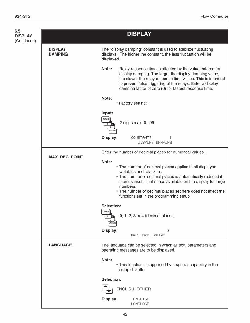
42
924-ST2 Flow Computer
The "display damping" constant is used to stabilize fl uctuating displays. The higher the constant, the less fl uctuation will be displayed.
Note: Relay response time is affected by the value entered for display damping. The larger the display damping value, the slower the relay response time will be. This is intended to prevent false triggering of the relays. Enter a display damping factor of zero (0) for fastest response time.
Note: • Factory setting: 1
Input:
2 digits max; 0...99
Display: CONSTANT? 1 DISPLAY DAMPING
Enter the number of decimal places for numerical values.
Note: • The number of decimal places applies to all displayed
variables and totalizers. • The number of decimal places is automatically reduced if
there is insuffi cient space available on the display for large numbers.
• The number of decimal places set here does not affect the functions set in the programming setup.
Selection:
0, 1, 2, 3 or 4 (decimal places)
Display: 3 MAX. DEC. POINT
The language can be selected in which all text, parameters and operating messages are to be displayed.
Note: • This function is supported by a special capability in the
setup diskette.
Selection:
ENGLISH, OTHER
Display: ENGLISH LANGUAGE
6.5DISPLAY(Continued)
DISPLAY
DISPLAY DAMPING
MAX. DEC. POINT
LANGUAGE
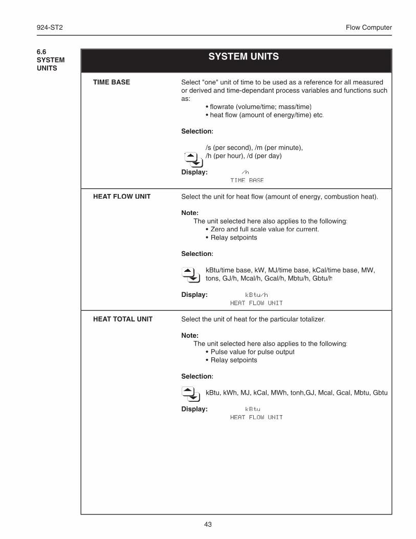
43
924-ST2 Flow Computer
SYSTEM UNITS
Select "one" unit of time to be used as a reference for all measured or derived and time-dependant process variables and functions such as: • fl owrate (volume/time; mass/time) • heat fl ow (amount of energy/time) etc.
Selection:
/s (per second), /m (per minute), /h (per hour), /d (per day) /h (per hour), /d (per day) /h (per hour), /d (per day) /h (per hour), /d (per day) /h (per hour), /d (per day) /h (per hour), /d (per day) /h (per hour), /d (per day) /h (per hour), /d (per day) /h (per hour), /d (per day) /h (per hour), /d (per day) /h (per hour), /d (per day)
Display: /h TIME BASE
Select the unit for heat fl ow (amount of energy, combustion heat).
Note: The unit selected here also applies to the following: • Zero and full scale value for current. • Relay setpoints
Selection:
kBtu/time base, kW, MJ/time base, kCal/time base, MW, kBtu/time base, kW, MJ/time base, kCal/time base, MW, kBtu/time base, kW, MJ/time base, kCal/time base, MW, kBtu/time base, kW, MJ/time base, kCal/time base, MW, kBtu/time base, kW, MJ/time base, kCal/time base, MW, kBtu/time base, kW, MJ/time base, kCal/time base, MW, kBtu/time base, kW, MJ/time base, kCal/time base, MW, kBtu/time base, kW, MJ/time base, kCal/time base, MW, kBtu/time base, kW, MJ/time base, kCal/time base, MW, tons, GJ/h, Mcal/h, Gcal/h, Mbtu/h, Gbtu/h
Display: kBtu/h HEAT FLOW UNIT
Select the unit of heat for the particular totalizer.
Note: The unit selected here also applies to the following: • Pulse value for pulse output • Relay setpoints
Selection:
kBtu, kWh, MJ, kCal, MWh, tonh,GJ, Mcal, Gcal, Mbtu, Gbtu
Display: kBtu HEAT FLOW UNIT
TIME BASE
HEAT FLOW UNIT
HEAT TOTAL UNIT
6.6SYSTEM UNITS
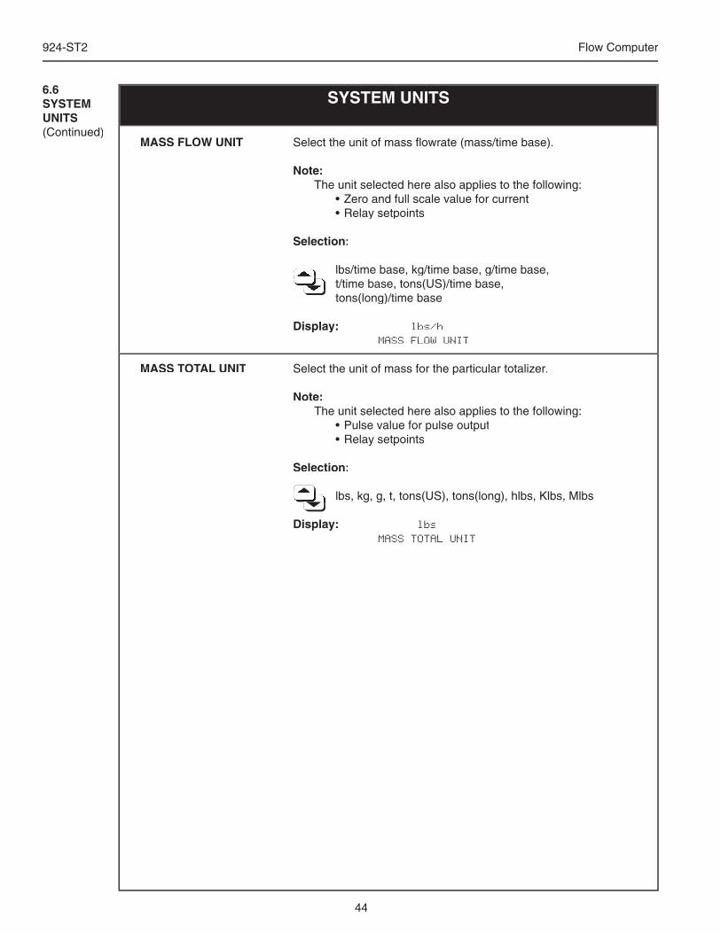
44
924-ST2 Flow Computer
Select the unit of mass fl owrate (mass/time base).
Note: The unit selected here also applies to the following: • Zero and full scale value for current • Relay setpoints
Selection:
lbs/time base, kg/time base, g/time base, lbs/time base, kg/time base, g/time base, lbs/time base, kg/time base, g/time base, lbs/time base, kg/time base, g/time base, lbs/time base, kg/time base, g/time base, lbs/time base, kg/time base, g/time base, lbs/time base, kg/time base, g/time base, t/time base, tons(US)/time base, t/time base, tons(US)/time base, t/time base, tons(US)/time base, t/time base, tons(US)/time base, t/time base, tons(US)/time base, t/time base, tons(US)/time base, t/time base, tons(US)/time base, t/time base, tons(US)/time base, t/time base, tons(US)/time base, t/time base, tons(US)/time base, t/time base, tons(US)/time base, tons(long)/time base tons(long)/time base tons(long)/time base tons(long)/time base tons(long)/time base
Display: lbs/h MASS FLOW UNIT
Select the unit of mass for the particular totalizer.
Note: The unit selected here also applies to the following: • Pulse value for pulse output • Relay setpoints
Selection:
lbs, kg, g, t, tons(US), tons(long), hlbs, Klbs, Mlbs lbs, kg, g, t, tons(US), tons(long), hlbs, Klbs, Mlbs lbs, kg, g, t, tons(US), tons(long), hlbs, Klbs, Mlbs lbs, kg, g, t, tons(US), tons(long), hlbs, Klbs, Mlbs lbs, kg, g, t, tons(US), tons(long), hlbs, Klbs, Mlbs lbs, kg, g, t, tons(US), tons(long), hlbs, Klbs, Mlbs lbs, kg, g, t, tons(US), tons(long), hlbs, Klbs, Mlbs lbs, kg, g, t, tons(US), tons(long), hlbs, Klbs, Mlbs lbs, kg, g, t, tons(US), tons(long), hlbs, Klbs, Mlbs lbs, kg, g, t, tons(US), tons(long), hlbs, Klbs, Mlbs lbs, kg, g, t, tons(US), tons(long), hlbs, Klbs, Mlbs lbs, kg, g, t, tons(US), tons(long), hlbs, Klbs, Mlbs lbs, kg, g, t, tons(US), tons(long), hlbs, Klbs, Mlbs
Display: lbs MASS TOTAL UNIT
SYSTEM UNITS6.6SYSTEM UNITS(Continued)
MASS FLOW UNIT
MASS TOTAL UNIT
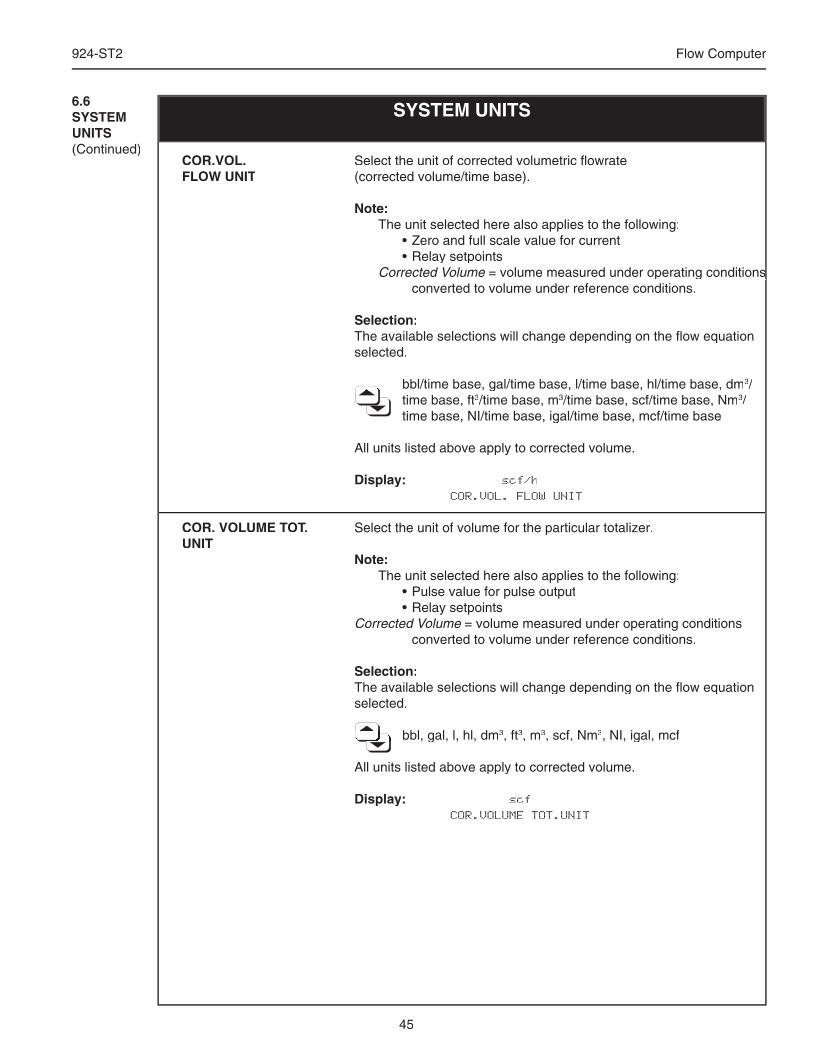
45
924-ST2 Flow Computer
SYSTEM UNITS
Select the unit of corrected volumetric fl owrate (corrected volume/time base).
Note: The unit selected here also applies to the following: • Zero and full scale value for current • Relay setpoints Corrected Volume = volume measured under operating conditions = volume measured under operating conditions
converted to volume under reference conditions.
Selection:The available selections will change depending on the fl ow equation selected.
bbl/time base, gal/time base, l/time base, hl/time base, dm bbl/time base, gal/time base, l/time base, hl/time base, dm bbl/time base, gal/time base, l/time base, hl/time base, dm bbl/time base, gal/time base, l/time base, hl/time base, dm bbl/time base, gal/time base, l/time base, hl/time base, dm bbl/time base, gal/time base, l/time base, hl/time base, dm bbl/time base, gal/time base, l/time base, hl/time base, dm3/time base, ft3/time base, m3/time base, scf/time base, Nm3/time base, NI/time base, igal/time base, mcf/time base
All units listed above apply to corrected volume.
Display: scf/h COR.VOL. FLOW UNIT
Select the unit of volume for the particular totalizer.
Note: The unit selected here also applies to the following: • Pulse value for pulse output • Relay setpointsCorrected Volume = volume measured under operating conditions
converted to volume under reference conditions.
Selection:The available selections will change depending on the fl ow equation selected.
bbl, gal, l, hl, dm bbl, gal, l, hl, dm bbl, gal, l, hl, dm bbl, gal, l, hl, dm bbl, gal, l, hl, dm bbl, gal, l, hl, dm bbl, gal, l, hl, dm bbl, gal, l, hl, dm bbl, gal, l, hl, dm bbl, gal, l, hl, dm bbl, gal, l, hl, dm bbl, gal, l, hl, dm bbl, gal, l, hl, dm3, ft3, m3, scf, Nm3, NI, igal, mcf
All units listed above apply to corrected volume.
Display: scf COR.VOLUME TOT.UNIT
COR.VOL. FLOW UNIT
COR. VOLUME TOT.UNIT
6.6SYSTEM UNITS(Continued)
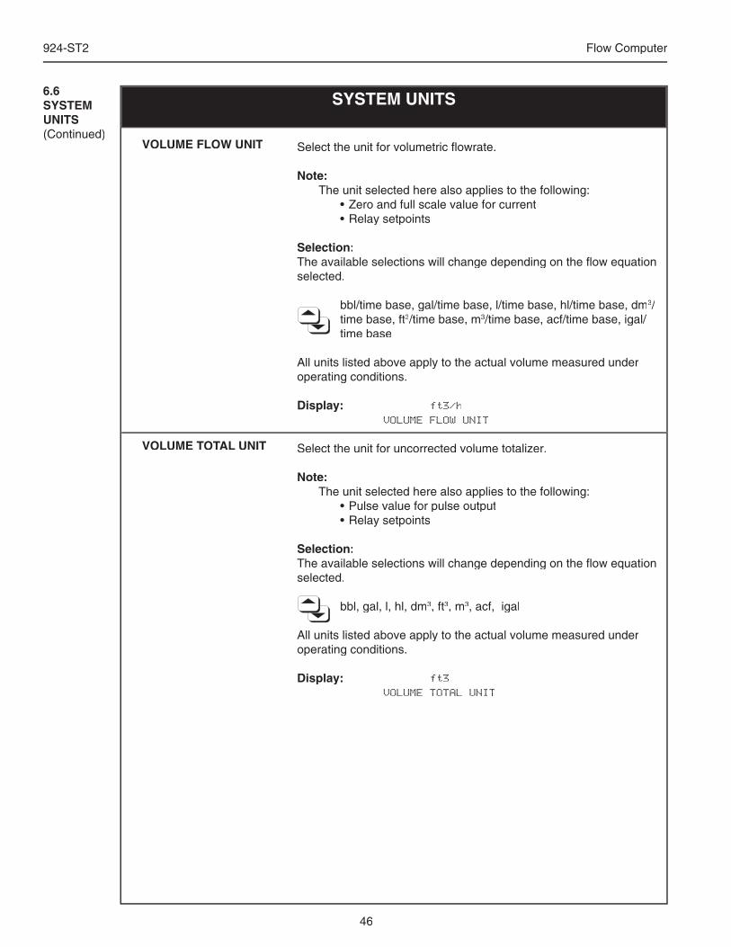
46
924-ST2 Flow Computer
Select the unit for volumetric fl owrate.
Note: The unit selected here also applies to the following: • Zero and full scale value for current • Relay setpoints
Selection:The available selections will change depending on the fl ow equation selected.
bbl/time base, gal/time base, l/time base, hl/time base, dm3/time base, ft3/time base, m3/time base, acf/time base, igal/time base
All units listed above apply to the actual volume measured under operating conditions.
Display: ft3/h VOLUME FLOW UNIT
Select the unit for uncorrected volume totalizer.
Note: The unit selected here also applies to the following: • Pulse value for pulse output • Relay setpoints
Selection:The available selections will change depending on the fl ow equation selected.
bbl, gal, l, hl, dm3, ft3, m3, acf, igal
All units listed above apply to the actual volume measured under operating conditions.
Display: ft3 VOLUME TOTAL UNIT
VOLUME FLOW UNIT
VOLUME TOTAL UNIT
SYSTEM UNITS6.6SYSTEM UNITS(Continued)
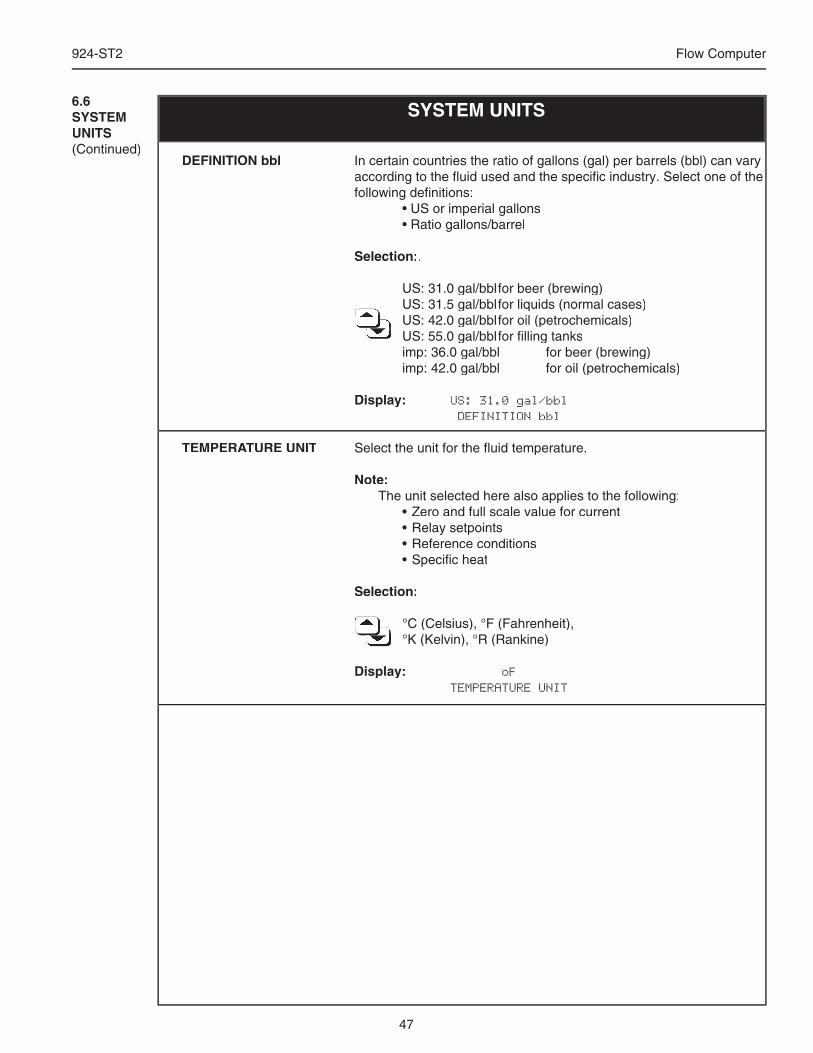
47
924-ST2 Flow Computer
SYSTEM UNITS6.6SYSTEM UNITS(Continued)
In certain countries the ratio of gallons (gal) per barrels (bbl) can vary according to the fl uid used and the specifi c industry. Select one of the following defi nitions: • US or imperial gallons • Ratio gallons/barrel
Selection:.
US: 31.0 gal/bbl for beer (brewing) US: 31.5 gal/bbl for liquids (normal cases) US: 31.5 gal/bbl for liquids (normal cases) US: 31.5 gal/bbl for liquids (normal cases) US: 31.5 gal/bbl for liquids (normal cases) US: 31.5 gal/bbl for liquids (normal cases) US: 42.0 gal/bbl for oil (petrochemicals) US: 42.0 gal/bbl for oil (petrochemicals) US: 42.0 gal/bbl for oil (petrochemicals) US: 42.0 gal/bbl for oil (petrochemicals) US: 42.0 gal/bbl for oil (petrochemicals) US: 42.0 gal/bbl for oil (petrochemicals) US: 42.0 gal/bbl for oil (petrochemicals) US: 42.0 gal/bbl for oil (petrochemicals) US: 42.0 gal/bbl for oil (petrochemicals) US: 42.0 gal/bbl for oil (petrochemicals) US: 42.0 gal/bbl for oil (petrochemicals) US: 55.0 gal/bbl for fi lling tanks US: 55.0 gal/bbl for fi lling tanks US: 55.0 gal/bbl for fi lling tanks US: 55.0 gal/bbl for fi lling tanks US: 55.0 gal/bbl for fi lling tanks US: 55.0 gal/bbl for fi lling tanks US: 55.0 gal/bbl for fi lling tanks imp: 36.0 gal/bbl for beer (brewing) imp: 42.0 gal/bbl for oil (petrochemicals)
Display: US: 31.0 gal/bbl DEFINITION bbl
Select the unit for the fl uid temperature.
Note: The unit selected here also applies to the following: • Zero and full scale value for current • Relay setpoints • Reference conditions • Specifi c heat
Selection:
°C (Celsius), °F (Fahrenheit), °C (Celsius), °F (Fahrenheit), °C (Celsius), °F (Fahrenheit), °C (Celsius), °F (Fahrenheit), °C (Celsius), °F (Fahrenheit), °C (Celsius), °F (Fahrenheit), °C (Celsius), °F (Fahrenheit), °C (Celsius), °F (Fahrenheit), °C (Celsius), °F (Fahrenheit), °C (Celsius), °F (Fahrenheit), °C (Celsius), °F (Fahrenheit), °K (Kelvin), °R (Rankine) °K (Kelvin), °R (Rankine) °K (Kelvin), °R (Rankine) °K (Kelvin), °R (Rankine) °K (Kelvin), °R (Rankine) °K (Kelvin), °R (Rankine) °K (Kelvin), °R (Rankine) °K (Kelvin), °R (Rankine) °K (Kelvin), °R (Rankine)
Display: oF TEMPERATURE UNIT
DEFINITION bbl
TEMPERATURE UNIT
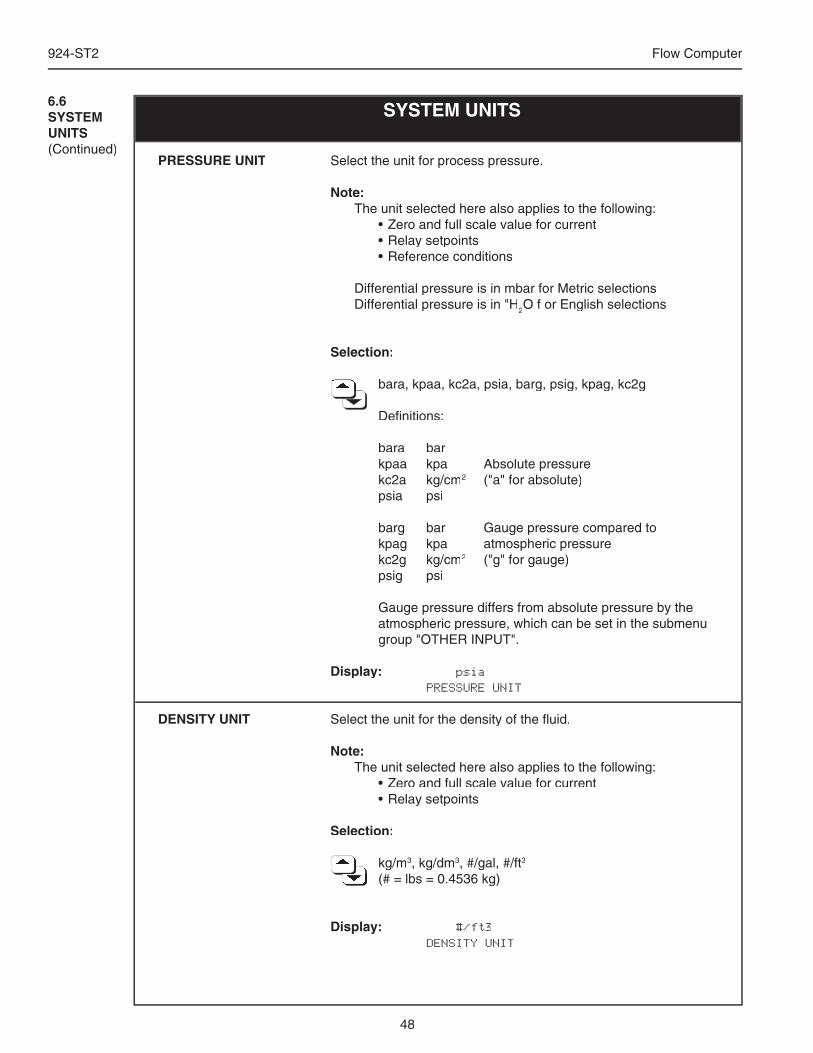
48
924-ST2 Flow Computer
SYSTEM UNITS6.6SYSTEM UNITS(Continued)
Select the unit for process pressure.
Note: The unit selected here also applies to the following: • Zero and full scale value for current • Relay setpoints • Reference conditions
Differential pressure is in mbar for Metric selections Differential pressure is in "H2O f or English selections
Selection:
bara, kpaa, kc2a, psia, barg, psig, kpag, kc2g bara, kpaa, kc2a, psia, barg, psig, kpag, kc2g bara, kpaa, kc2a, psia, barg, psig, kpag, kc2g bara, kpaa, kc2a, psia, barg, psig, kpag, kc2g bara, kpaa, kc2a, psia, barg, psig, kpag, kc2g bara, kpaa, kc2a, psia, barg, psig, kpag, kc2g bara, kpaa, kc2a, psia, barg, psig, kpag, kc2g bara, kpaa, kc2a, psia, barg, psig, kpag, kc2g bara, kpaa, kc2a, psia, barg, psig, kpag, kc2g
Defi nitions:
bara bar kpaa kpa Absolute pressure kc2a kg/cm2 ("a" for absolute) psia psi
barg bar Gauge pressure compared to kpag kpa atmospheric pressure kc2g kg/cm2 ("g" for gauge) psig psi
Gauge pressure differs from absolute pressure by the atmospheric pressure, which can be set in the submenu group "OTHER INPUT".
Display: psia PRESSURE UNIT
Select the unit for the density of the fl uid.
Note: The unit selected here also applies to the following: • Zero and full scale value for current • Relay setpoints
Selection:
kg/m kg/m kg/m kg/m kg/m kg/m kg/m kg/m kg/m kg/m kg/m3, kg/dm3, #/gal, #/ft3
(# = lbs = 0.4536 kg) (# = lbs = 0.4536 kg) (# = lbs = 0.4536 kg) (# = lbs = 0.4536 kg) (# = lbs = 0.4536 kg) (# = lbs = 0.4536 kg) (# = lbs = 0.4536 kg) (# = lbs = 0.4536 kg) (# = lbs = 0.4536 kg)
Display: #/ft3 DENSITY UNIT
PRESSURE UNIT
DENSITY UNIT
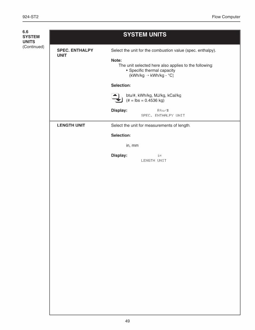
49
924-ST2 Flow Computer
SYSTEM UNITS6.6SYSTEM UNITS(Continued)
Select the unit for the combustion value (spec. enthalpy).
Note: The unit selected here also applies to the following: • Specifi c thermal capacity (kWh/kg → kWh/kg - °C)
Selection:
btu/#, kWh/kg, MJ/kg, kCal/kg btu/#, kWh/kg, MJ/kg, kCal/kg btu/#, kWh/kg, MJ/kg, kCal/kg btu/#, kWh/kg, MJ/kg, kCal/kg btu/#, kWh/kg, MJ/kg, kCal/kg btu/#, kWh/kg, MJ/kg, kCal/kg btu/#, kWh/kg, MJ/kg, kCal/kg btu/#, kWh/kg, MJ/kg, kCal/kg btu/#, kWh/kg, MJ/kg, kCal/kg btu/#, kWh/kg, MJ/kg, kCal/kg btu/#, kWh/kg, MJ/kg, kCal/kg (# = lbs = 0.4536 kg) (# = lbs = 0.4536 kg) (# = lbs = 0.4536 kg) (# = lbs = 0.4536 kg) (# = lbs = 0.4536 kg) (# = lbs = 0.4536 kg) (# = lbs = 0.4536 kg) (# = lbs = 0.4536 kg) (# = lbs = 0.4536 kg)
Display: Btu/# SPEC. ENTHALPY UNIT
Select the unit for measurements of length.
Selection:
in, mm
Display: in LENGTH UNIT
SPEC. ENTHALPY UNIT
LENGTH UNIT
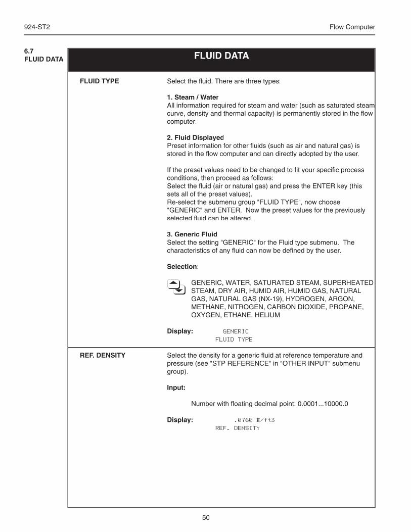
50
924-ST2 Flow Computer
FLUID DATA6.7FLUID DATA
Select the fl uid. There are three types:
1. Steam / WaterAll information required for steam and water (such as saturated steam All information required for steam and water (such as saturated steam curve, density and thermal capacity) is permanently stored in the fl ow computer.
2. Fluid DisplayedPreset information for other fl uids (such as air and natural gas) is stored in the fl ow computer and can directly adopted by the user.
If the preset values need to be changed to fi t your specifi c process conditions, then proceed as follows:Select the fl uid (air or natural gas) and press the ENTER key (this sets all of the preset values).Re-select the submenu group "FLUID TYPE", now choose "GENERIC" and ENTER. Now the preset values for the previously selected fl uid can be altered.
3. Generic FluidSelect the setting "GENERIC" for the Fluid type submenu. The characteristics of any fl uid can now be defi ned by the user.
Selection:
GENERIC, WATER, SATURATED STEAM, SUPERHEATED STEAM, DRY AIR, HUMID AIR, HUMID GAS, NATURAL GAS, NATURAL GAS (NX-19), HYDROGEN, ARGON, METHANE, NITROGEN, CARBON DIOXIDE, PROPANE, OXYGEN, ETHANE, HELIUM
Display: GENERIC FLUID TYPE
Select the density for a generic fl uid at reference temperature and pressure (see "STP REFERENCE" in "OTHER INPUT" submenu group).
Input:
Number with fl oating decimal point: 0.0001...10000.0
Display: .0760 #/ft3 REF. DENSITY
FLUID TYPE
REF. DENSITY
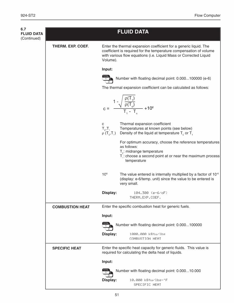
51
924-ST2 Flow Computer
Enter the thermal expansion coeffi cient for a generic liquid. The coeffi cient is required for the temperature compensation of volume with various fl ow equations (i.e. Liquid Mass or Corrected Liquid Volume).
Input:
Number with fl oating decimal point: 0.000...100000 (e-6)
The thermal expansion coeffi cient can be calculated as follows:
(T1)
(To)
T1
- To
1 -
c =
c Thermal expansion coeffi cientT0,T1 Temperatures at known points (see below)ρ (T0,T1) Density of the liquid at temperature T0 or T1
For optimum accuracy, choose the reference temperatures as follows:
T0: midrange temperature T1: choose a second point at or near the maximum process temperature
106 The value entered is internally multiplied by a factor of 10-6
(display: e-6/temp. unit) since the value to be entered is very small.
Display: 104.300 (e-6/oF) THERM.EXP.COEF.
Enter the specifi c combustion heat for generic fuels.
Input:
Number with fl oating decimal point: 0.000...100000
Display: 1000.000 kBtu/lbs COMBUSTION HEAT
Enter the specifi c heat capacity for generic fl uids. This value is required for calculating the delta heat of liquids.
Input:
Number with fl oating decimal point: 0.000...10.000
Display: 10.000 kBtu/lbs-°F SPECIFIC HEAT
FLUID DATA6.7FLUID DATA(Continued)
THERM. EXP. COEF.
COMBUSTION HEAT
SPECIFIC HEAT
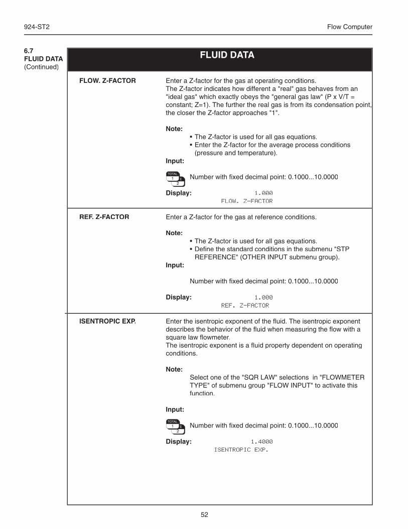
52
924-ST2 Flow Computer
Enter a Z-factor for the gas at operating conditions. The Z-factor indicates how different a "real" gas behaves from an "ideal gas" which exactly obeys the "general gas law" (P x V/T = constant; Z=1). The further the real gas is from its condensation point, the closer the Z-factor approaches "1".
Note: • The Z-factor is used for all gas equations. • Enter the Z-factor for the average process conditions
(pressure and temperature).Input:
Number with fi xed decimal point: 0.1000...10.0000
Display: 1.000 FLOW. Z-FACTOR
Enter a Z-factor for the gas at reference conditions.
Note: • The Z-factor is used for all gas equations. • Defi ne the standard conditions in the submenu "STP
REFERENCE" (OTHER INPUT submenu group).Input:
Number with fi xed decimal point: 0.1000...10.0000
Display: 1.000 REF. Z-FACTOR
Enter the isentropic exponent of the fl uid. The isentropic exponent describes the behavior of the fl uid when measuring the fl ow with a square law fl owmeter.The isentropic exponent is a fl uid property dependent on operating conditions.
Note: Select one of the "SQR LAW" selections in "FLOWMETER
TYPE" of submenu group "FLOW INPUT" to activate this function.
Input:
Number with fi xed decimal point: 0.1000...10.0000
Display: 1.4000 ISENTROPIC EXP.
FLUID DATA6.7FLUID DATA(Continued)
FLOW. Z-FACTOR
REF. Z-FACTOR
ISENTROPIC EXP.
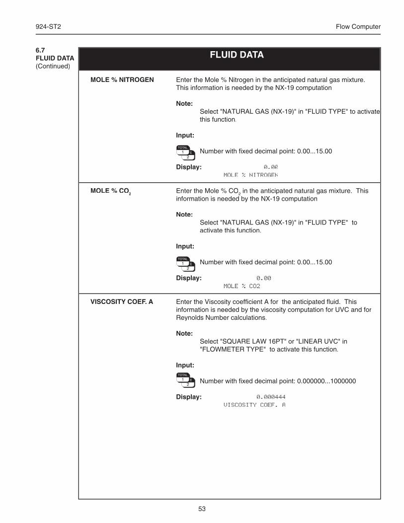
53
924-ST2 Flow Computer
Enter the Mole % Nitrogen in the anticipated natural gas mixture. This information is needed by the NX-19 computation
Note: Select "NATURAL GAS (NX-19)" in "FLUID TYPE" to activate
this function.
Input:
Number with fi xed decimal point: 0.00...15.00
Display: 0.00 MOLE % NITROGEN
Enter the Mole % CO2 in the anticipated natural gas mixture. This information is needed by the NX-19 computation
Note: Select "NATURAL GAS (NX-19)" in "FLUID TYPE" to
activate this function.
Input:
Number with fi xed decimal point: 0.00...15.00
Display: 0.00 MOLE % CO2
Enter the Viscosity coeffi cient A for the anticipated fl uid. This information is needed by the viscosity computation for UVC and for Reynolds Number calculations.
Note: Select "SQUARE LAW 16PT" or "LINEAR UVC" in
"FLOWMETER TYPE" to activate this function.
Input:
Number with fi xed decimal point: 0.000000...1000000
Display: 0.000444 VISCOSITY COEF. A
FLUID DATA6.7FLUID DATA(Continued)
MOLE % NITROGEN
MOLE % CO2
VISCOSITY COEF. A
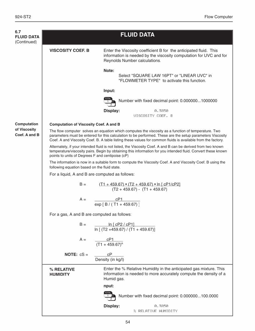
54
924-ST2 Flow Computer
Enter the Viscosity coeffi cient B for the anticipated fl uid. This information is needed by the viscosity computation for UVC and for Reynolds Number calculations.
Note: Select "SQUARE LAW 16PT" or "LINEAR UVC" in
"FLOWMETER TYPE" to activate this function.
Input:
Number with fi xed decimal point: 0.000000...1000000
Display: 0.3850 VISCOSITY COEF. B
FLUID DATA6.7FLUID DATA(Continued)
VISCOSITY COEF. B
Computation of Viscosity Coef. A and B
The fl ow computer solves an equation which computes the viscosity as a function of temperature. Two parameters must be entered for this calculation to be performed. These are the setup parameters Viscosity Coef. A and Viscosity Coef. B. A table listing these values for common fl uids is available from the factory.
Alternately, if your intended fl uid is not listed, the Viscosity Coef. A and B can be derived from two known temperature/viscosity pairs. Begin by obtaining this information for you intended fl uid. Convert these known points to units of Degrees F and centipoise (cP)
The information is now in a suitable form to compute the Viscosity Coef. A and Viscosity Coef. B using the following equation based on the fl uid state.
For a liquid, A and B are computed as follows:
B = (T1 + 459.67) • (T2 + 459.67) • ln [ cP1/cP2]T1 + 459.67) • (T2 + 459.67) • ln [ cP1/cP2] (T2 + 459.67) - (T1 + 459.67)
A = cP1 . exp [ B / ( T1 + 459.67) ]
For a gas, A and B are computed as follows:
B = ln [ cP2 / cP1] ln [ cP2 / cP1] . ln [ (T2 +459.67) / (T1 + 459.67)]
A = cP1 . (T1 + 459.67)B
NOTE: cS = cP . Density (in kg/l)
Computation of Viscosity Coef. A and B
Enter the % Relative Humidity in the anticipated gas mixture. This information is needed to more accurately compute the density of a Humid gas.
nput:
Number with fi xed decimal point: 0.000000...100.0000
Display: 0.3850 % RELATIVE HUMIDITY
% RELATIVE HUMIDITY

55
924-ST2 Flow Computer
6.8FLOW INPUT FLOW INPUT
Select the fl owmeter type. The fl ow equation (see SYSTEM PARAMETERS) and the fl owmeter selected here determine the basic operation of the fl ow computer.
.
Selection:
LINEAR Volumetric fl owmeter with linear pulse or analog output.
SQR LAW Differential pressure transmitter without square root extraction, with analog output.
SQR LAW-LIN. Differential pressure transmitter with square root extraction and analog output.
LINEAR 16 PT* Volumetric fl owmeter with nonlinear pulse or analog output; with 16 point linearization table.
SQR LAW 16 PT* Differential pressure transmitter without square root extraction, with
analog output and 16 point linearization table.
SQR LAW-LIN. 16 PT* Differential pressure transmitter with square root extraction, analog
output and 16 point linearization table.
LINEAR UVC Volumetric Turbine fl owmeter with UVC calibration curve documentation and pulse output.
LINEAR MANIFOLD Linear manifold consists of 2 linear fl owmeters used in conjunction with an external bypass/diverter value. It may be used with turbine, PD, Mag, Vortex fl owmeters equipped with analog outputs to extend the allowable turndown range.
GILFLO Gilfl o fl owmeters are special purpose differential pressure type fl owmeters with an analog output where the differential pressure is linear with fl ow.
GILFLO 16PT Gilfl o 16 PT fl owmeters are special purpose differential pressure type fl owmeters with an analog output where the differential pressure is approximately linear with fl ow, but can be further enhanced by a 16 point linearization table.
BYPASS BYPASS is a selection for use with Bypass(Shuntfl ow) fl owmeters equipped with a pulse output.
ILVA 16PT ILVA 16 PT fl owmeters are special purpose differential pressure type fl owmeters with an analog output where the differential pressure is approximately linear with fl ow, but can be further enhanced by a 16 point linearization table.
* A linearization table must be entered by user. (see "LINEARIZATION" submenu).
Display: LINEAR FLOWMETER TYPE
FLOWMETER TYPE
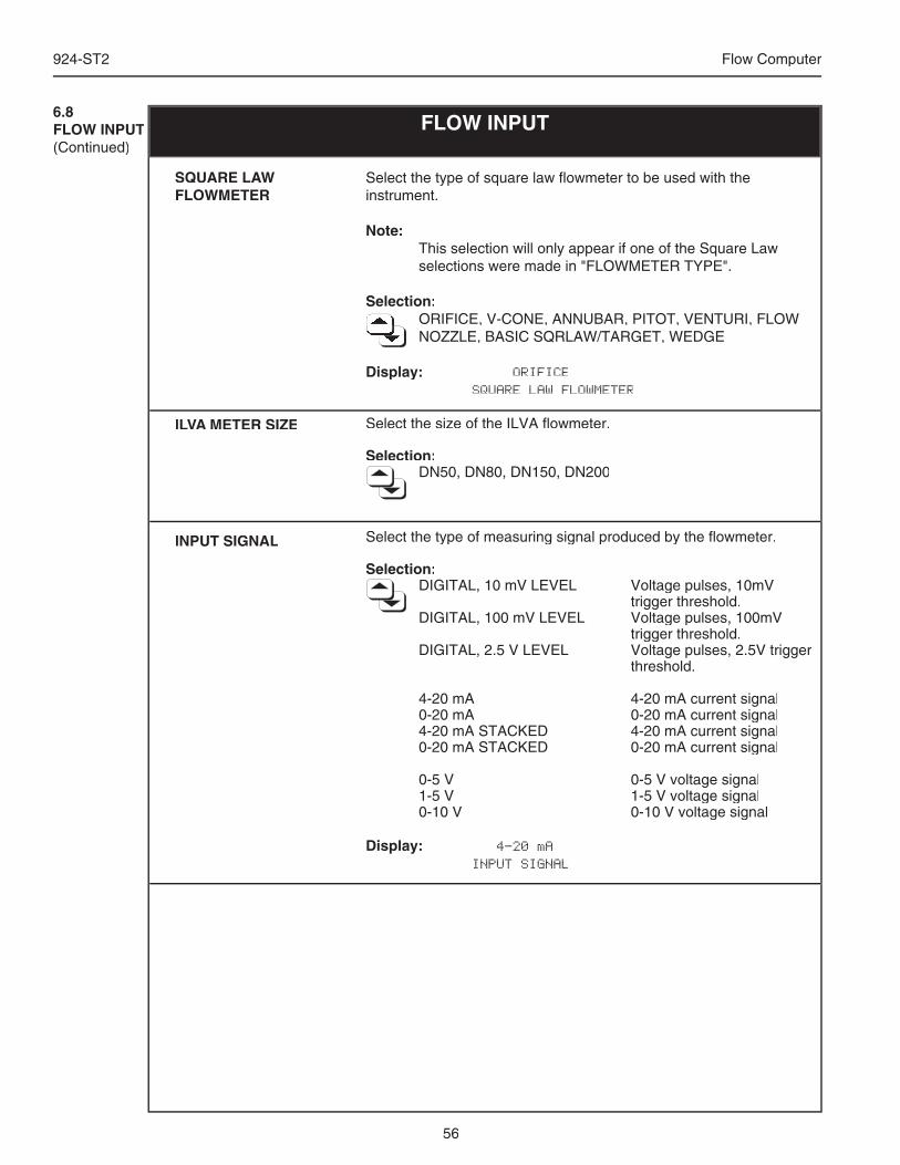
56
924-ST2 Flow Computer
6.8FLOW INPUT(Continued)
FLOW INPUT
Select the type of square law fl owmeter to be used with the instrument.
Note: This selection will only appear if one of the Square Law
selections were made in "FLOWMETER TYPE".
Selection: ORIFICE, V-CONE, ANNUBAR, PITOT, VENTURI, FLOW ORIFICE, V-CONE, ANNUBAR, PITOT, VENTURI, FLOW ORIFICE, V-CONE, ANNUBAR, PITOT, VENTURI, FLOW ORIFICE, V-CONE, ANNUBAR, PITOT, VENTURI, FLOW ORIFICE, V-CONE, ANNUBAR, PITOT, VENTURI, FLOW ORIFICE, V-CONE, ANNUBAR, PITOT, VENTURI, FLOW ORIFICE, V-CONE, ANNUBAR, PITOT, VENTURI, FLOW NOZZLE, BASIC SQRLAW/TARGET, WEDGE NOZZLE, BASIC SQRLAW/TARGET, WEDGE NOZZLE, BASIC SQRLAW/TARGET, WEDGE NOZZLE, BASIC SQRLAW/TARGET, WEDGE NOZZLE, BASIC SQRLAW/TARGET, WEDGE NOZZLE, BASIC SQRLAW/TARGET, WEDGE NOZZLE, BASIC SQRLAW/TARGET, WEDGE NOZZLE, BASIC SQRLAW/TARGET, WEDGE NOZZLE, BASIC SQRLAW/TARGET, WEDGE NOZZLE, BASIC SQRLAW/TARGET, WEDGE NOZZLE, BASIC SQRLAW/TARGET, WEDGE
Display: ORIFICE SQUARE LAW FLOWMETER
Select the size of the ILVA fl owmeter.
Selection: DN50, DN80, DN150, DN200
Select the type of measuring signal produced by the fl owmeter.
Selection: DIGITAL, 10 mV LEVEL Voltage pulses, 10mV
trigger threshold. DIGITAL, 100 mV LEVEL Voltage pulses, 100mV
trigger threshold. DIGITAL, 2.5 V LEVEL Voltage pulses, 2.5V trigger
threshold.
4-20 mA 4-20 mA current signal 0-20 mA 0-20 mA current signal 4-20 mA STACKED 4-20 mA current signal 0-20 mA STACKED 0-20 mA current signal
0-5 V 0-5 V voltage signal 1-5 V 1-5 V voltage signal 0-10 V 0-10 V voltage signal
Display: 4-20 mA INPUT SIGNAL
SQUARE LAWFLOWMETER
ILVA METER SIZE
INPUT SIGNAL
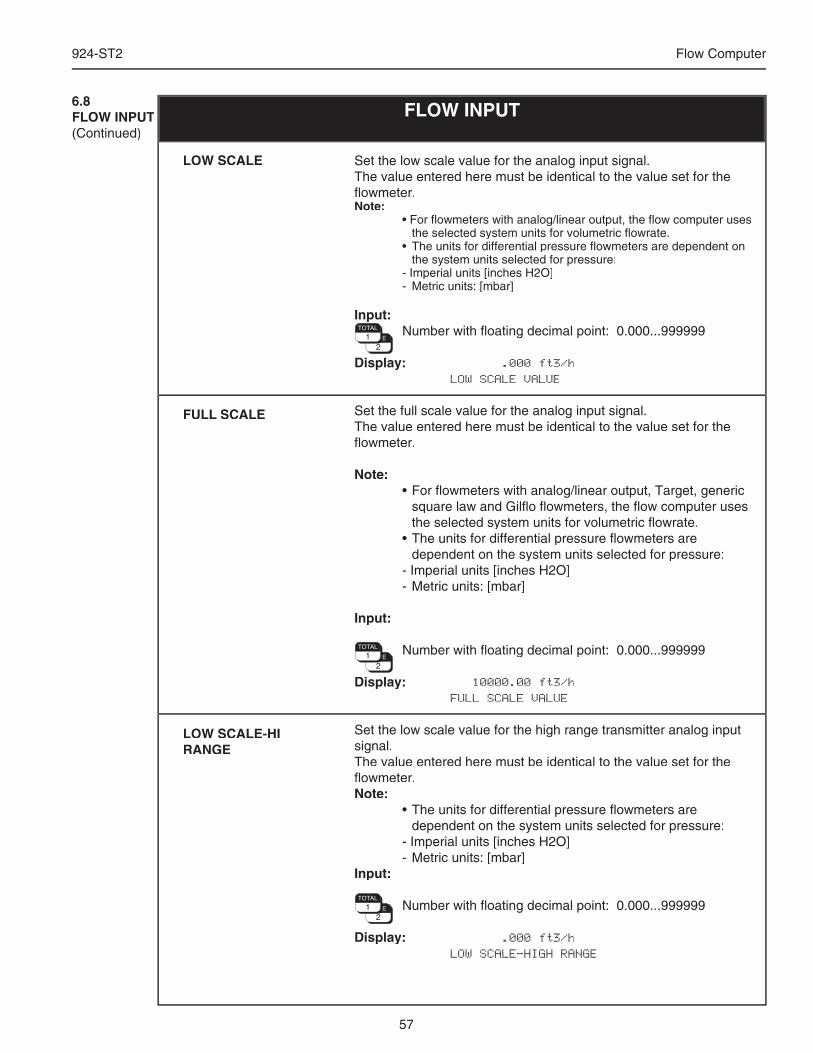
57
924-ST2 Flow Computer
FLOW INPUT
Set the low scale value for the analog input signal.The value entered here must be identical to the value set for the fl owmeter.Note: • For fl owmeters with analog/linear output, the fl ow computer uses
the selected system units for volumetric fl owrate. • The units for differential pressure fl owmeters are dependent on
the system units selected for pressure: - Imperial units [inches H2O] - Metric units: [mbar]
Input: Number with fl oating decimal point: 0.000...999999
Display: .000 ft3/h LOW SCALE VALUE
Set the full scale value for the analog input signal.The value entered here must be identical to the value set for the fl owmeter.
Note: • For fl owmeters with analog/linear output, Target, generic
square law and Gilfl o fl owmeters, the fl ow computer uses the selected system units for volumetric fl owrate.
• The units for differential pressure fl owmeters are dependent on the system units selected for pressure:
- Imperial units [inches H2O] - Metric units: [mbar]
Input:
Number with fl oating decimal point: 0.000...999999
Display: 10000.00 ft3/h FULL SCALE VALUE
Set the low scale value for the high range transmitter analog input signal.The value entered here must be identical to the value set for the fl owmeter.Note: • The units for differential pressure fl owmeters are
dependent on the system units selected for pressure: - Imperial units [inches H2O] - Metric units: [mbar]Input:
Number with fl oating decimal point: 0.000...999999
Display: .000 ft3/h LOW SCALE-HIGH RANGE
LOW SCALE
FULL SCALE
LOW SCALE-HI RANGE
6.8FLOW INPUT(Continued)
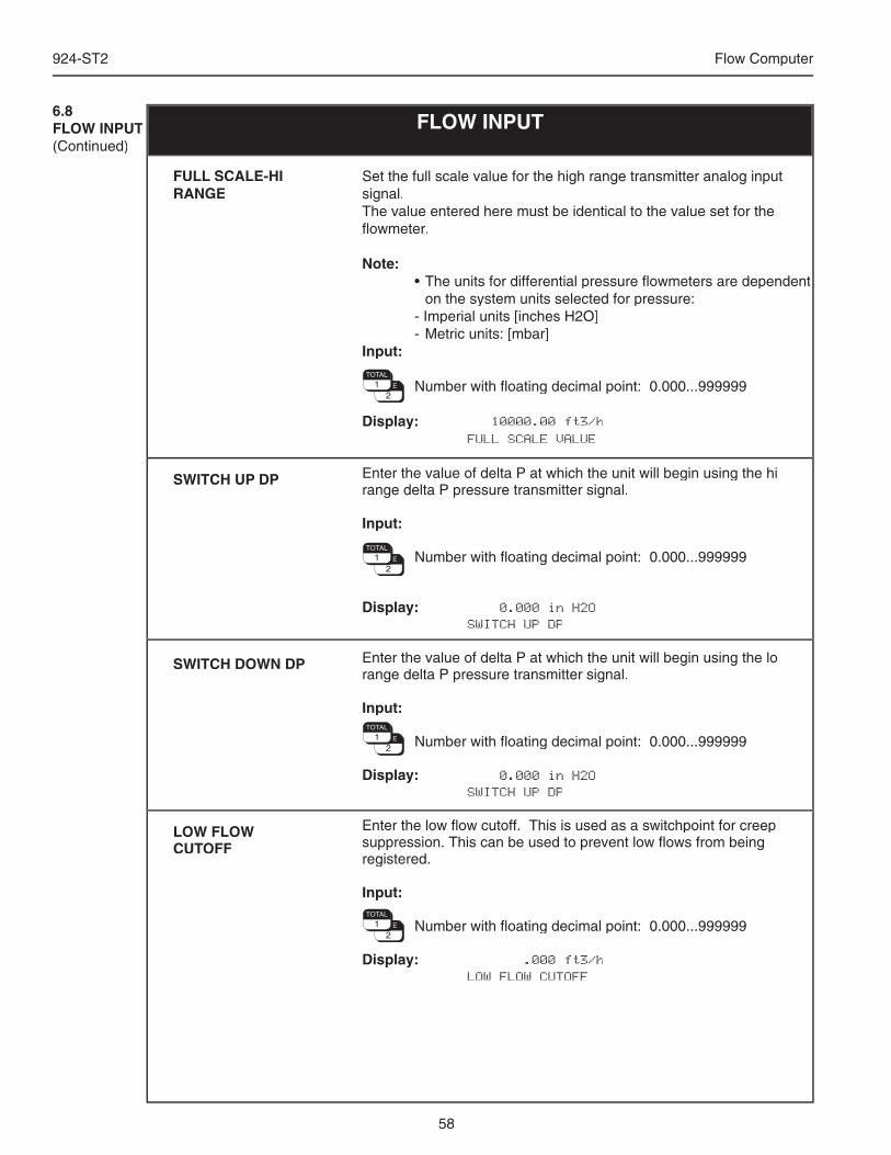
58
924-ST2 Flow Computer
Set the full scale value for the high range transmitter analog input signal.The value entered here must be identical to the value set for the fl owmeter.
Note: • The units for differential pressure fl owmeters are dependent
on the system units selected for pressure: - Imperial units [inches H2O] - Metric units: [mbar]Input:
Number with fl oating decimal point: 0.000...999999
Display: 10000.00 ft3/h FULL SCALE VALUE
Enter the value of delta P at which the unit will begin using the hi range delta P pressure transmitter signal.
Input:
Number with fl oating decimal point: 0.000...999999
Display: 0.000 in H2O SWITCH UP DP
Enter the value of delta P at which the unit will begin using the lo range delta P pressure transmitter signal.
Input:
Number with fl oating decimal point: 0.000...999999
Display: 0.000 in H2O SWITCH UP DP
Enter the low fl ow cutoff. This is used as a switchpoint for creep suppression. This can be used to prevent low fl ows from being registered.
Input:
Number with fl oating decimal point: 0.000...999999
Display: .000 ft3/h LOW FLOW CUTOFF
6.8FLOW INPUT(Continued)
FLOW INPUT
FULL SCALE-HI RANGE
SWITCH UP DP
SWITCH DOWN DP
LOW FLOW CUTOFF
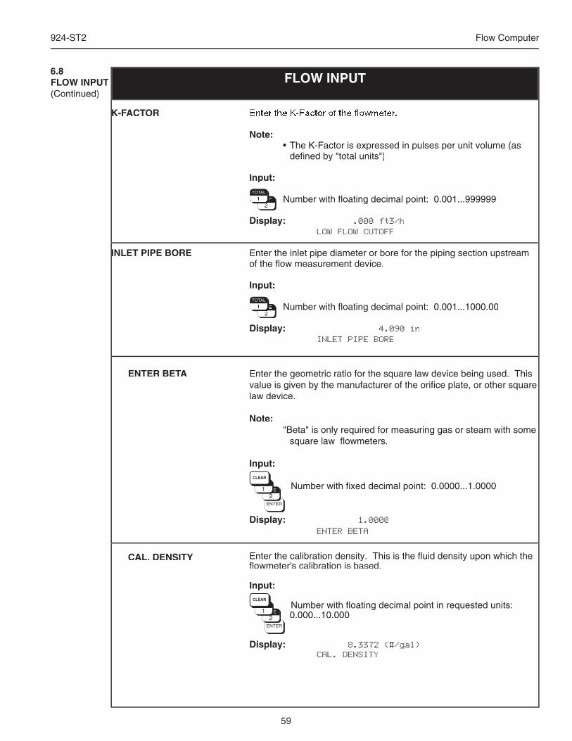
59
924-ST2 Flow Computer
FLOW INPUT6.8FLOW INPUT(Continued)
Enter the geometric ratio for the square law device being used. This value is given by the manufacturer of the orifi ce plate, or other square law device.
Note: "Beta" is only required for measuring gas or steam with some
square law fl owmeters.
Input:
Number with fi xed decimal point: 0.0000...1.0000
Display: 1.0000 ENTER BETA
ENTER BETA
CAL. DENSITY Enter the calibration density. This is the fl uid density upon which the fl owmeter's calibration is based.
Input:
Number with fl oating decimal point in requested units: 0.000...10.000
Display: 8.3372 (#/gal) CAL. DENSITY
Enter the K-Factor of the fl owmeter.
Note: • The K-Factor is expressed in pulses per unit volume (as
defi ned by "total units")
Input:
Number with fl oating decimal point: 0.001...999999 Number with fl oating decimal point: 0.001...999999 Number with fl oating decimal point: 0.001...999999 Number with fl oating decimal point: 0.001...999999 Number with fl oating decimal point: 0.001...999999 Number with fl oating decimal point: 0.001...999999 Number with fl oating decimal point: 0.001...999999 Number with fl oating decimal point: 0.001...999999 Number with fl oating decimal point: 0.001...999999 Number with fl oating decimal point: 0.001...999999 Number with fl oating decimal point: 0.001...999999 Number with fl oating decimal point: 0.001...999999 Number with fl oating decimal point: 0.001...999999 Number with fl oating decimal point: 0.001...999999 Number with fl oating decimal point: 0.001...999999
Display: .000 ft3/h LOW FLOW CUTOFF
Enter the inlet pipe diameter or bore for the piping section upstream of the fl ow measurement device.
Input:
Number with fl oating decimal point: 0.001...1000.00 Number with fl oating decimal point: 0.001...1000.00 Number with fl oating decimal point: 0.001...1000.00 Number with fl oating decimal point: 0.001...1000.00 Number with fl oating decimal point: 0.001...1000.00 Number with fl oating decimal point: 0.001...1000.00 Number with fl oating decimal point: 0.001...1000.00 Number with fl oating decimal point: 0.001...1000.00 Number with fl oating decimal point: 0.001...1000.00 Number with fl oating decimal point: 0.001...1000.00 Number with fl oating decimal point: 0.001...1000.00 Number with fl oating decimal point: 0.001...1000.00 Number with fl oating decimal point: 0.001...1000.00 Number with fl oating decimal point: 0.001...1000.00 Number with fl oating decimal point: 0.001...1000.00 Number with fl oating decimal point: 0.001...1000.00
Display: 4.090 in INLET PIPE BORE
K-FACTOR
INLET PIPE BORE
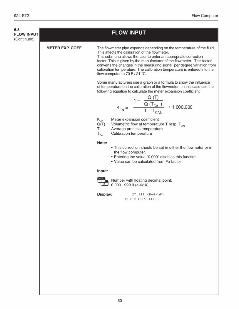
60
924-ST2 Flow Computer
FLOW INPUT6.8FLOW INPUT(Continued)
The fl owmeter pipe expands depending on the temperature of the fl uid. This affects the calibration of the fl owmeter.This submenu allows the user to enter an appropriate correction factor. This is given by the manufacturer of the fl owmeter. This factor converts the changes in the measuring signal per degree variation from calibration temperature. The calibration temperature is entered into the fl ow computer to 70 F / 21 °C.
Some manufacturers use a graph or a formula to show the infl uence of temperature on the calibration of the fl owmeter. In this case use the following equation to calculate the meter expansion coeffi cient:
KME Meter expansion coeffi cientQ(T) Volumetric fl ow at temperature T resp. TCAL
T Average process temperatureTCAL Calibration temperature
Note: • This correction should be set in either the fl owmeter or in
the fl ow computer. • Entering the value "0.000" disables this function • Value can be calculated from Fa factor
Input:
Number with fl oating decimal point: 0.000...999.9 (e-6/°X)
Display: 27.111 (E-6/oF) METER EXP. COEF.
METER EXP. COEF.
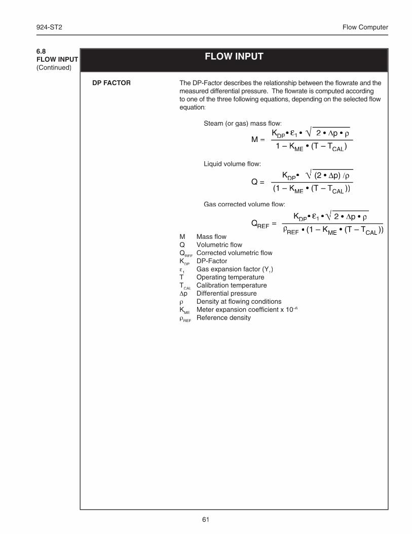
61
924-ST2 Flow Computer
The DP-Factor describes the relationship between the fl owrate and the measured differential pressure. The fl owrate is computed according to one of the three following equations, depending on the selected fl ow equation:
Steam (or gas) mass fl ow:
Liquid volume fl ow:
Gas corrected volume fl ow:
M Mass fl owQ Volumetric fl owQREF Corrected volumetric fl owKDP DP-Factorε1 Gas expansion factor (Y1)T Operating temperatureTCAL Calibration temperature Δp Differential pressureρ Density at fl owing conditionsKME Meter expansion coeffi cient x 10–6
ρREF Reference density
DP FACTOR
6.8FLOW INPUT(Continued)
FLOW INPUT
2 • ∆p • ρ1 – KME • (T – TCAL)
√KDP ε1• •ε• •ε1• •1M =
(2 • ∆p) /ρ(1 – KME • (T – TCAL ))
√ (2 • √ (2 • KDP•Q =
2 • ∆p • ρ(1 – KME • (T – TCAL ))
√ 2 • √ 2 • QREF =
KDP ε1• •ε• •ε1• •1
ρREF •
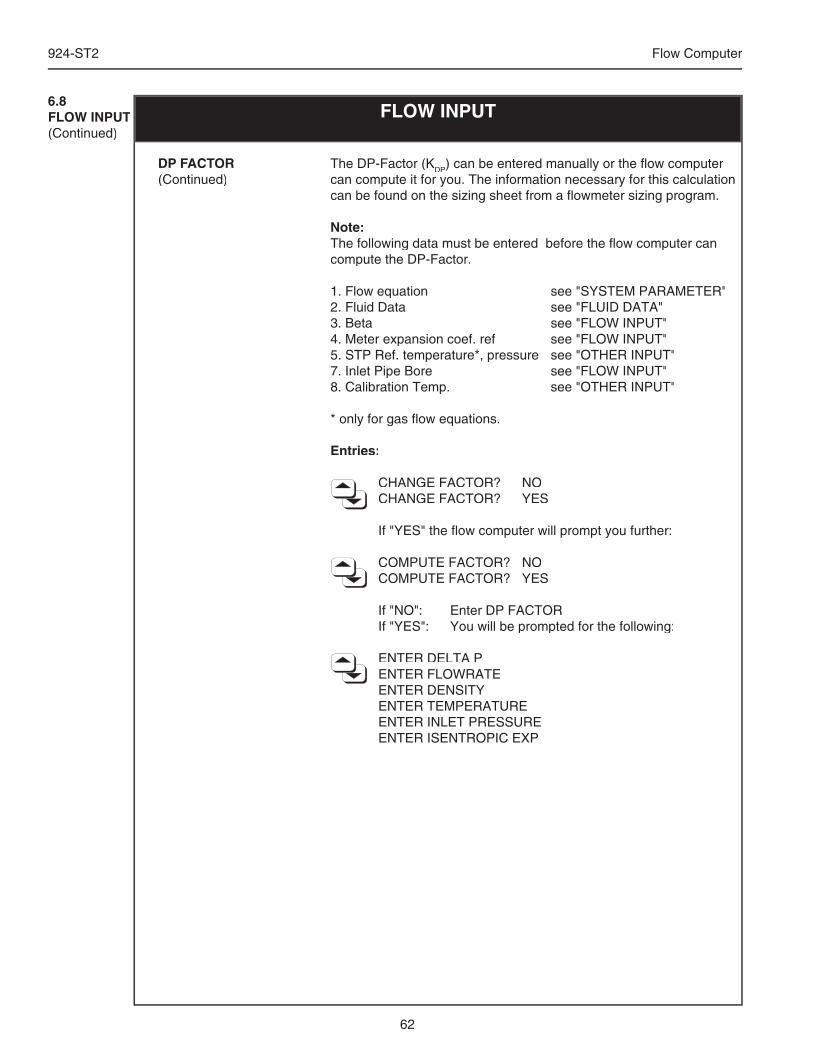
62
924-ST2 Flow Computer
The DP-Factor (KDP) can be entered manually or the fl ow computer can compute it for you. The information necessary for this calculation can be found on the sizing sheet from a fl owmeter sizing program.
Note:The following data must be entered before the fl ow computer can compute the DP-Factor.
1. Flow equation see "SYSTEM PARAMETER"2. Fluid Data see "FLUID DATA"3. Beta see "FLOW INPUT"4. Meter expansion coef. ref see "FLOW INPUT"5. STP Ref. temperature*, pressure see "OTHER INPUT"7. Inlet Pipe Bore see "FLOW INPUT"8. Calibration Temp. see "OTHER INPUT"
* only for gas fl ow equations.
Entries:
CHANGE FACTOR? NO CHANGE FACTOR? YES
If "YES" the fl ow computer will prompt you further:
COMPUTE FACTOR? NO COMPUTE FACTOR? YES
If "NO": Enter DP FACTOR If "YES": You will be prompted for the following:
ENTER DELTA P ENTER FLOWRATE ENTER DENSITY ENTER TEMPERATURE ENTER INLET PRESSURE ENTER ISENTROPIC EXP
DP FACTOR(Continued)
6.8FLOW INPUT(Continued)
FLOW INPUT
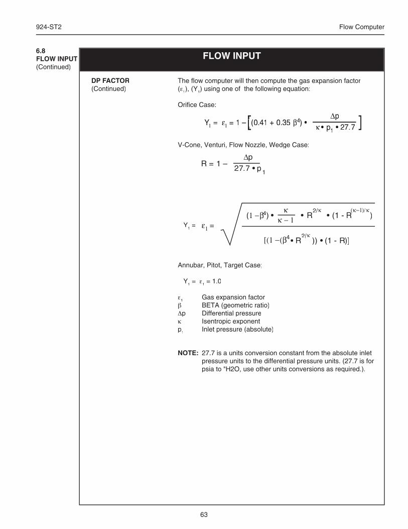
63
924-ST2 Flow Computer
FLOW INPUT6.8FLOW INPUT(Continued)
The fl ow computer will then compute the gas expansion factor (ε1), (Y1) using one of the following equation:
Orifi ce Case:
V-Cone, Venturi, Flow Nozzle, Wedge Case:
Y1 =
Annubar, Pitot, Target Case;
Y1 = ε1 = 1.0
ε1 Gas expansion factorβ BETA (geometric ratio)Δp Differential pressureκ Isentropic exponentp1 Inlet pressure (absolute)
DP FACTOR(Continued)
∆p27.7 • p1
R = 1 –
κ − 11 −β4β4β ) •(κ
• R2/κ• (1 - R
(κ−1R
(κ−1R
)/κ)
[(1 −(β •4 R )) • (1 - R)]2/R )2/R )
κε1 =
NOTE: 27.7 is a units conversion constant from the absolute inlet pressure units to the differential pressure units. (27.7 is for psia to "H2O, use other units conversions as required.).
∆p• p1
ε1 = 1 – ([ ]∆[ ]∆p[ ]pκ[ ]κ • p[ ]• p1
[ ]1 •[ ]• 27.[ ]27.7[ ]7[ ]– ([ ]– (0.41[ ]0.41 + 0[ ]+ 0.3[ ].35[ ]5 β[ ]β4[ ]4) •[ ]) •Y =1Y 1Y
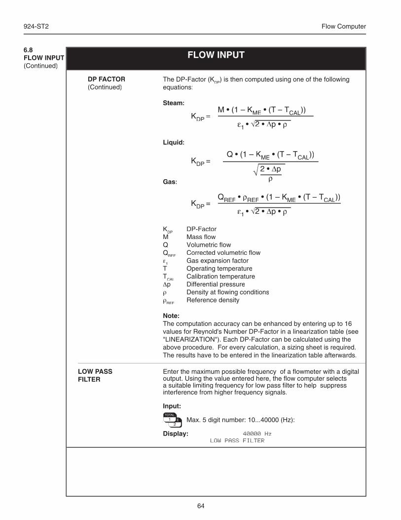
64
924-ST2 Flow Computer
Enter the maximum possible frequency of a fl owmeter with a digital output. Using the value entered here, the fl ow computer selects a suitable limiting frequency for low pass fi lter to help suppress interference from higher frequency signals.
Input:
Max. 5 digit number: 10...40000 (Hz):
Display: 40000 Hz LOW PASS FILTER
LOW PASS FILTER
DP FACTOR(Continued)
The DP-Factor (KDP) is then computed using one of the following equations:
Steam:
Liquid:
Gas:
KDP DP-FactorM Mass fl owQ Volumetric fl owQREF Corrected volumetric fl owε1 Gas expansion factorT Operating temperatureTCAL Calibration temperature Δp Differential pressureρ Density at fl owing conditionsρREF Reference density
Note:The computation accuracy can be enhanced by entering up to 16 values for Reynold's Number DP-Factor in a linearization table (see "LINEARIZATION"). Each DP-Factor can be calculated using the above procedure. For every calculation, a sizing sheet is required. The results have to be entered in the linearization table afterwards.
QREF • ρREF • (1 – KME • (T – • (T – • (T TCAL))
ε1 • √2 • ∆p • ρKDP =
Q • (1 – KME • (T – • (T – • (T TCAL))
2 • ∆pρ
KDP =
M • (1 – KME • (T – • (T – • (T TCAL))
ε1 • √2 • ∆p • ρKDP =
6.8FLOW INPUT(Continued)
FLOW INPUT
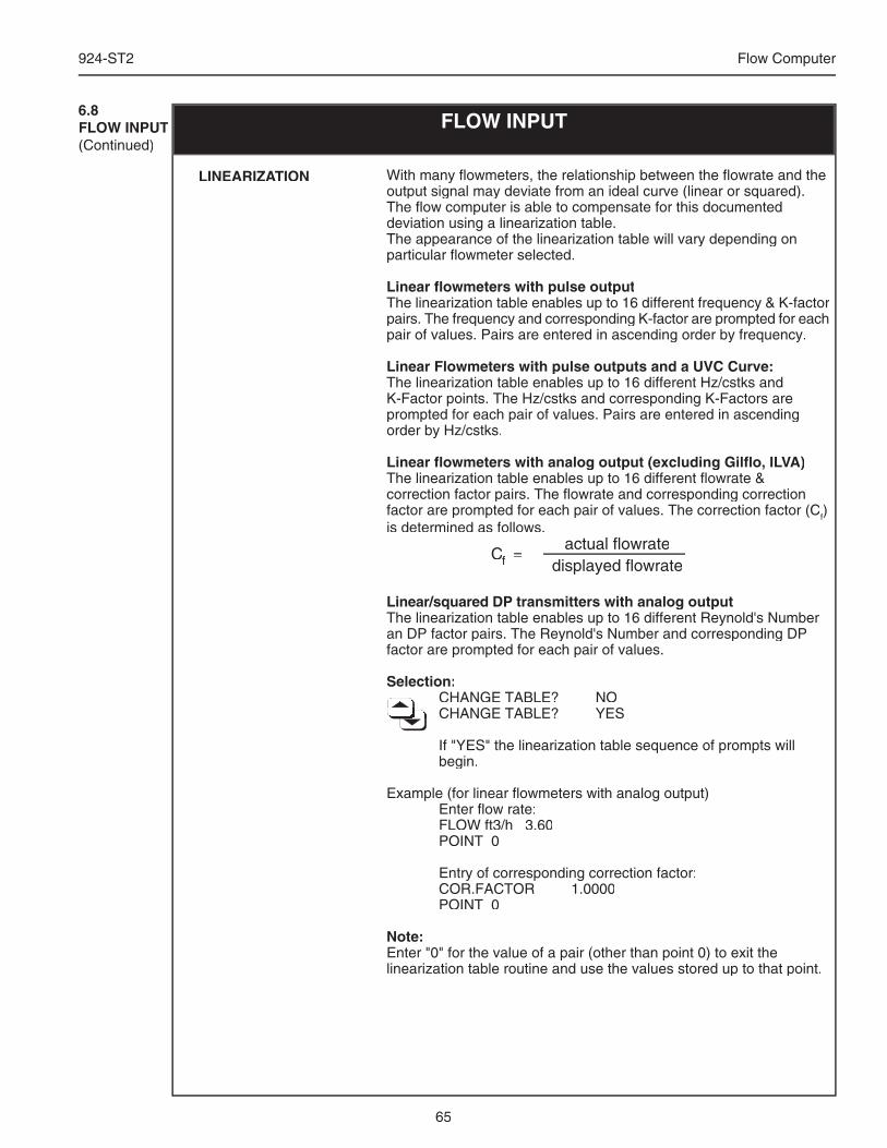
65
924-ST2 Flow Computer
6.8FLOW INPUT(Continued)
FLOW INPUT
With many fl owmeters, the relationship between the fl owrate and the output signal may deviate from an ideal curve (linear or squared). The fl ow computer is able to compensate for this documented deviation using a linearization table.The appearance of the linearization table will vary depending on particular fl owmeter selected.
Linear fl owmeters with pulse outputThe linearization table enables up to 16 different frequency & K-factor pairs. The frequency and corresponding K-factor are prompted for each pair of values. Pairs are entered in ascending order by frequency.
Linear Flowmeters with pulse outputs and a UVC Curve:The linearization table enables up to 16 different Hz/cstks and K-Factor points. The Hz/cstks and corresponding K-Factors are prompted for each pair of values. Pairs are entered in ascending order by Hz/cstks.
Linear fl owmeters with analog output (excluding Gilfl o, ILVA)The linearization table enables up to 16 different fl owrate & correction factor pairs. The fl owrate and corresponding correction factor are prompted for each pair of values. The correction factor (Cf) is determined as follows.
Cf Cf C =
actual flowratedisplayed flowrate
Linear/squared DP transmitters with analog outputThe linearization table enables up to 16 different Reynold's Number an DP factor pairs. The Reynold's Number and corresponding DP factor are prompted for each pair of values.
Selection: CHANGE TABLE? NO CHANGE TABLE? NO CHANGE TABLE? NO CHANGE TABLE? NO CHANGE TABLE? NO CHANGE TABLE? NO CHANGE TABLE? NO CHANGE TABLE? YES CHANGE TABLE? YES CHANGE TABLE? YES CHANGE TABLE? YES CHANGE TABLE? YES CHANGE TABLE? YES CHANGE TABLE? YES CHANGE TABLE? YES CHANGE TABLE? YES
If "YES" the linearization table sequence of prompts will begin.
Example (for linear fl owmeters with analog output) Enter fl ow rate: FLOW ft3/h 3.60 POINT 0
Entry of corresponding correction factor: COR.FACTOR 1.0000 POINT 0
Note:Enter "0" for the value of a pair (other than point 0) to exit the linearization table routine and use the values stored up to that point.
LINEARIZATION
66
924-ST2 Flow Computer
Enter the Flowmeter Location
Selection:
Hot, Cold:
Display: COLD FLOWMETER LOCATION
Enter the Bypass Calibration Factor.
Input:
Max. 6 digit number: 0.000001...999999
Display: 1.000000 BYPASS CAL. FACTOR
Enter the Bypass EAm Factor.
Input:
Max. 6 digit number: 0.000001...999999
Display: 1.000000 BYPASS EAM FACTOR
Enter the Bypass DC Factor.
Input:
Max. 6 digit number: 0.1...10.0
Display: 1.000000 BYPASS DC FACTOR
Enter the Bypass Ym Factor.
Input:
Max. 6 digit number: 0.001...1.0
Display: 1.000000 BYPASS YM FACTOR
6.8FLOW INPUT(Continued)
FLOW INPUT
VIEW INPUT SIGNAL This feature is used to see the present value of the fl ow input signal. The type of electrical signal is determined by the fl owmeter input signal type selection.
Display: 150 Hz VIEW INPUT SIGNAL
BYPASS CAL. FACTOR
BYPASS EAmFACTOR
BYPASS DCFACTOR
BYPASS YmFACTOR
FLOWMETER LOCATION
VIEW HIGH RANGE SIGNAL
This feature is used to see the present value of the high range fl ow input signal. The type of electrical signal is determined by the fl owmeter input signal type selection.
Display: 4 mA VIEW HIGH RANGE SIGNAL
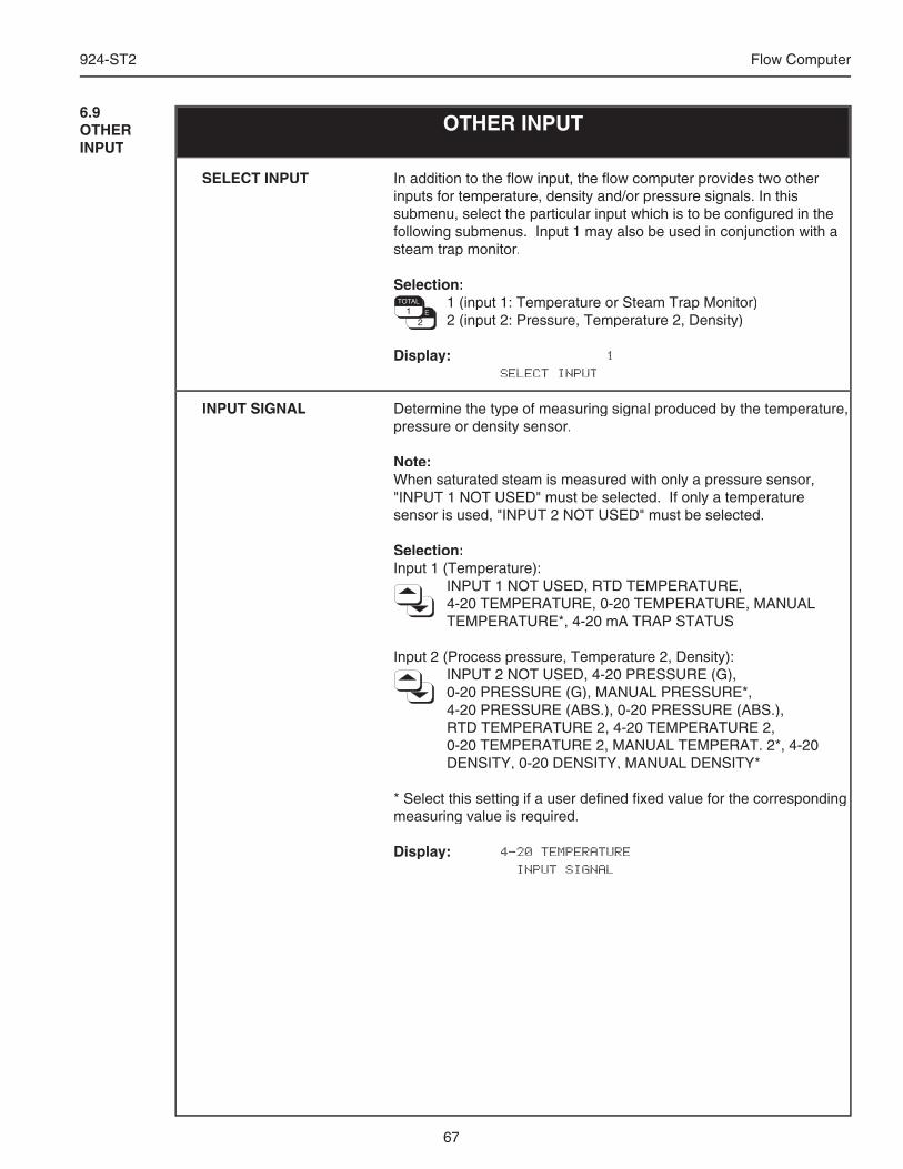
67
924-ST2 Flow Computer
In addition to the fl ow input, the fl ow computer provides two other inputs for temperature, density and/or pressure signals. In this submenu, select the particular input which is to be confi gured in the following submenus. Input 1 may also be used in conjunction with a steam trap monitor.
Selection: 1 (input 1: Temperature or Steam Trap Monitor) 2 (input 2: Pressure, Temperature 2, Density)
Display: 1 SELECT INPUT
Determine the type of measuring signal produced by the temperature, pressure or density sensor.
Note:When saturated steam is measured with only a pressure sensor, "INPUT 1 NOT USED" must be selected. If only a temperature sensor is used, "INPUT 2 NOT USED" must be selected.
Selection:Input 1 (Temperature): INPUT 1 NOT USED, RTD TEMPERATURE, 4-20 TEMPERATURE, 0-20 TEMPERATURE, MANUAL
TEMPERATURE*, 4-20 mA TRAP STATUS
Input 2 (Process pressure, Temperature 2, Density): INPUT 2 NOT USED, 4-20 PRESSURE (G), 0-20 PRESSURE (G), MANUAL PRESSURE*, 4-20 PRESSURE (ABS.), 0-20 PRESSURE (ABS.), RTD TEMPERATURE 2, 4-20 TEMPERATURE 2, 0-20 TEMPERATURE 2, MANUAL TEMPERAT. 2*, 4-20
DENSITY, 0-20 DENSITY, MANUAL DENSITY*
* Select this setting if a user defi ned fi xed value for the corresponding measuring value is required.
Display: 4-20 TEMPERATURE INPUT SIGNAL
6.9OTHER INPUT
OTHER INPUT
SELECT INPUT
INPUT SIGNAL
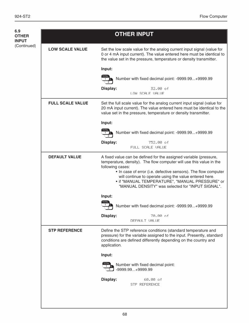
68
924-ST2 Flow Computer
6.9OTHER INPUT(Continued)
OTHER INPUT
Set the low scale value for the analog current input signal (value for 0 or 4 mA input current). The value entered here must be identical to the value set in the pressure, temperature or density transmitter.
Input:
Number with fi xed decimal point: -9999.99...+9999.99
Display: 32.00 of LOW SCALE VALUE
Set the full scale value for the analog current input signal (value for 20 mA input current). The value entered here must be identical to the value set in the pressure, temperature or density transmitter.
Input:
Number with fi xed decimal point: -9999.99...+9999.99
Display: 752.00 of FULL SCALE VALUE
A fi xed value can be defi ned for the assigned variable (pressure, temperature, density). The fl ow computer will use this value in the following cases: • In case of error (i.e. defective sensors). The fl ow computer
will continue to operate using the value entered here. • if "MANUAL TEMPERATURE", "MANUAL PRESSURE" or
"MANUAL DENSITY" was selected for "INPUT SIGNAL".
Input:
Number with fi xed decimal point: -9999.99...+9999.99
Display: 70.00 of DEFAULT VALUE
Defi ne the STP reference conditions (standard temperature and pressure) for the variable assigned to the input. Presently, standard conditions are defi ned differently depending on the country and application.
Input:
Number with fi xed decimal point: -9999.99...+9999.99
Display: 60.00 of STP REFERENCE
LOW SCALE VALUE
FULL SCALE VALUE
DEFAULT VALUE
STP REFERENCE
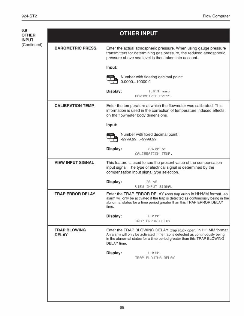
69
924-ST2 Flow Computer
OTHER INPUT6.9OTHER INPUT(Continued)
Enter the actual atmospheric pressure. When using gauge pressure transmitters for determining gas pressure, the reduced atmospheric pressure above sea level is then taken into account.
Input:
Number with fl oating decimal point: 0.0000...10000.0
Display: 1.013 bara BAROMETRIC PRESS.
Enter the temperature at which the fl owmeter was calibrated. This information is used in the correction of temperature induced effects on the fl owmeter body dimensions.
Input:
Number with fi xed decimal point: -9999.99...+9999.99
Display: 68.00 of CALIBRATION TEMP.
BAROMETRIC PRESS.
CALIBRATION TEMP.
This feature is used to see the present value of the compensation input signal. The type of electrical signal is determined by the compensation input signal type selection.
Display: 20 mA VIEW INPUT SIGNAL
VIEW INPUT SIGNAL
Enter the TRAP ERROR DELAY (cold trap error) in HH:MM format. An alarm will only be activated if the trap is detected as continuously being in the abnormal states for a time period greater than this TRAP ERROR DELAY time.
Display: HH:MM TRAP ERROR DELAY
TRAP ERROR DELAY
Enter the TRAP BLOWING DELAY (trap stuck open) in HH:MM format. An alarm will only be activated if the trap is detected as continuously being in the abnormal states for a time period greater than this TRAP BLOWING DELAY time.
Display: HH:MM TRAP BLOWING DELAY
TRAP BLOWING DELAY
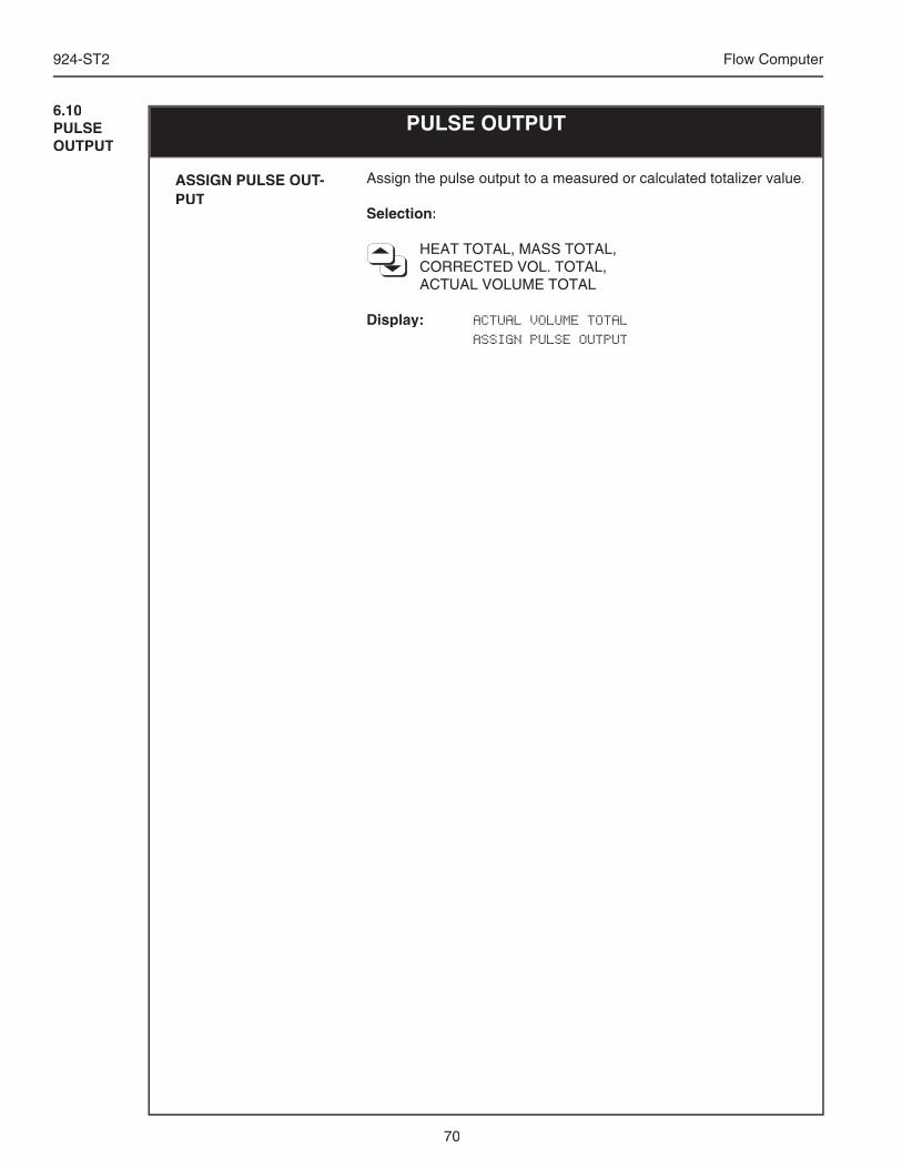
70
924-ST2 Flow Computer
6.10PULSE OUTPUT
PULSE OUTPUT
Assign the pulse output to a measured or calculated totalizer value.
Selection:
HEAT TOTAL, MASS TOTAL, CORRECTED VOL. TOTAL, ACTUAL VOLUME TOTAL
Display: ACTUAL VOLUME TOTAL
ASSIGN PULSE OUTPUT
ASSIGN PULSE OUT-PUT
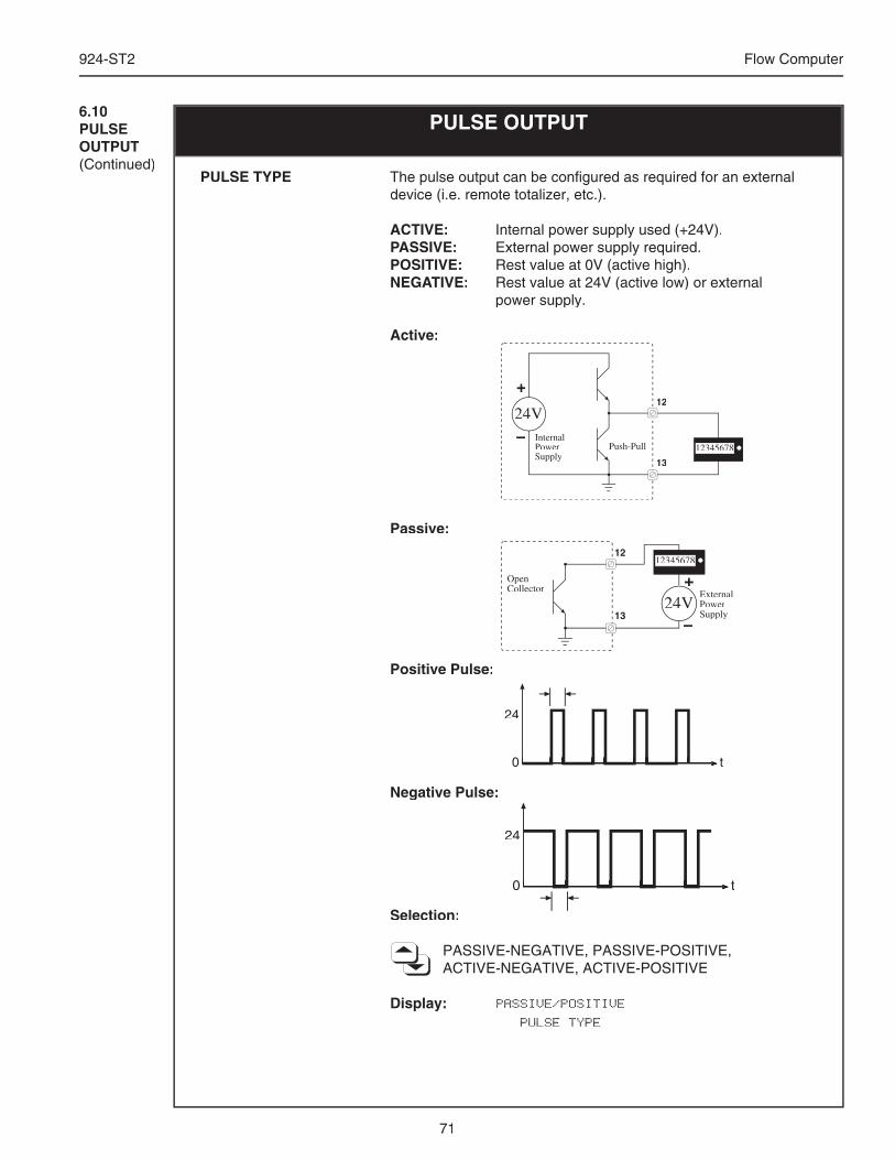
71
924-ST2 Flow Computer
6.10PULSE OUTPUT(Continued)
PULSE OUTPUT
The pulse output can be confi gured as required for an external device (i.e. remote totalizer, etc.).
ACTIVE: Internal power supply used (+24V).PASSIVE: External power supply required.POSITIVE: Rest value at 0V (active high).NEGATIVE: Rest value at 24V (active low) or external power supply.
Active:
Passive:
Positive Pulse:
Negative Pulse:
Selection:
PASSIVE-NEGATIVE, PASSIVE-POSITIVE, ACTIVE-NEGATIVE, ACTIVE-POSITIVE
Display: PASSIVE/POSITIVE
PULSE TYPE
24V
12345678
13
12
Push-PullInternalPowerSupply
+
–
12345678
13
12
OpenCollector
24VExternalPowerSupply
+
–
24
0 t0 t0 t0 t
24
0 t0 t0 t0 t
PULSE TYPE
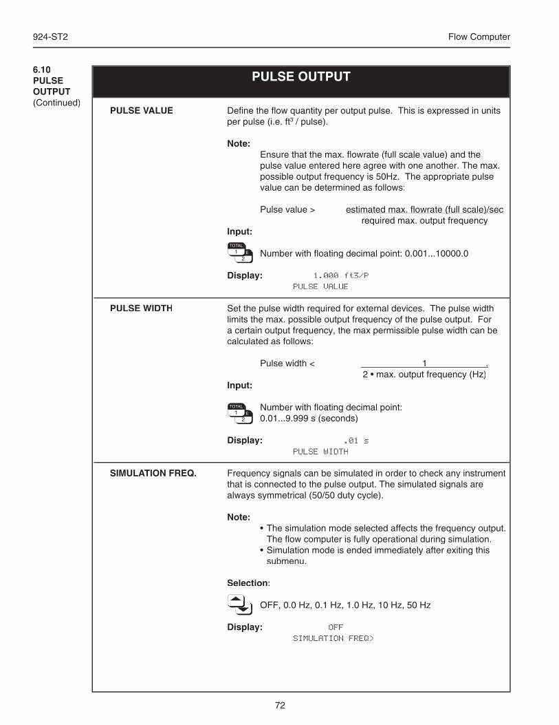
72
924-ST2 Flow Computer
6.10PULSE OUTPUT(Continued)
PULSE OUTPUT
Defi ne the fl ow quantity per output pulse. This is expressed in units per pulse (i.e. ft3 / pulse).
Note: Ensure that the max. fl owrate (full scale value) and the
pulse value entered here agree with one another. The max. possible output frequency is 50Hz. The appropriate pulse value can be determined as follows:
Pulse value > estimated max. fl owrate (full scale)/secestimated max. fl owrate (full scale)/sec required max. output frequencyInput:
Number with fl oating decimal point: 0.001...10000.0
Display: 1.000 ft3/P PULSE VALUE
Set the pulse width required for external devices. The pulse width limits the max. possible output frequency of the pulse output. For a certain output frequency, the max permissible pulse width can be calculated as follows:
Pulse width < 1 . 2 • max. output frequency (Hz)Input:
Number with fl oating decimal point: 0.01...9.999 s (seconds)
Display: .01 s PULSE WIDTH
Frequency signals can be simulated in order to check any instrument that is connected to the pulse output. The simulated signals are always symmetrical (50/50 duty cycle).
Note: • The simulation mode selected affects the frequency output.
The fl ow computer is fully operational during simulation. • Simulation mode is ended immediately after exiting this
submenu.
Selection:
OFF, 0.0 Hz, 0.1 Hz, 1.0 Hz, 10 Hz, 50 Hz OFF, 0.0 Hz, 0.1 Hz, 1.0 Hz, 10 Hz, 50 Hz OFF, 0.0 Hz, 0.1 Hz, 1.0 Hz, 10 Hz, 50 Hz OFF, 0.0 Hz, 0.1 Hz, 1.0 Hz, 10 Hz, 50 Hz OFF, 0.0 Hz, 0.1 Hz, 1.0 Hz, 10 Hz, 50 Hz OFF, 0.0 Hz, 0.1 Hz, 1.0 Hz, 10 Hz, 50 Hz OFF, 0.0 Hz, 0.1 Hz, 1.0 Hz, 10 Hz, 50 Hz OFF, 0.0 Hz, 0.1 Hz, 1.0 Hz, 10 Hz, 50 Hz OFF, 0.0 Hz, 0.1 Hz, 1.0 Hz, 10 Hz, 50 Hz OFF, 0.0 Hz, 0.1 Hz, 1.0 Hz, 10 Hz, 50 Hz OFF, 0.0 Hz, 0.1 Hz, 1.0 Hz, 10 Hz, 50 Hz
Display: OFF SIMULATION FREQ>
PULSE VALUE
PULSE WIDTH
SIMULATION FREQ.
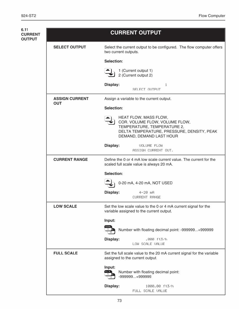
73
924-ST2 Flow Computer
6.11CURRENT OUTPUT
CURRENT OUTPUT
Select the current output to be confi gured. The fl ow computer offers two current outputs.
Selection:
1 (Current output 1) 1 (Current output 1) 1 (Current output 1) 1 (Current output 1) 1 (Current output 1) 1 (Current output 1) 1 (Current output 1) 1 (Current output 1) 1 (Current output 1) 1 (Current output 1) 1 (Current output 1) 2 (Current output 2) 2 (Current output 2) 2 (Current output 2) 2 (Current output 2) 2 (Current output 2) 2 (Current output 2) 2 (Current output 2) 2 (Current output 2)
Display: 1 SELECT OUTPUT
Assign a variable to the current output.
Selection:
HEAT FLOW, MASS FLOW, COR. VOLUME FLOW, VOLUME FLOW, TEMPERATURE, TEMPERATURE 2, DELTA TEMPERATURE, PRESSURE, DENSITY, PEAK
DEMAND, DEMAND LAST HOUR
Display: VOLUME FLOW ASSIGN CURRENT OUT.
Defi ne the 0 or 4 mA low scale current value. The current for the scaled full scale value is always 20 mA.
Selection:
0-20 mA, 4-20 mA, NOT USED
Display: 4-20 mA CURRENT RANGE
Set the low scale value to the 0 or 4 mA current signal for the variable assigned to the current output.
Input:
Number with fl oating decimal point: -999999...+999999
Display: .000 ft3/h LOW SCALE VALUE
Set the full scale value to the 20 mA current signal for the variable assigned to the current output.
Input: Number with fl oating decimal point: Number with fl oating decimal point: Number with fl oating decimal point: Number with fl oating decimal point: Number with fl oating decimal point: Number with fl oating decimal point: Number with fl oating decimal point: Number with fl oating decimal point: Number with fl oating decimal point: Number with fl oating decimal point: Number with fl oating decimal point: Number with fl oating decimal point: Number with fl oating decimal point: Number with fl oating decimal point: Number with fl oating decimal point: Number with fl oating decimal point: Number with fl oating decimal point: Number with fl oating decimal point: -999999...+999999 -999999...+999999 -999999...+999999 -999999...+999999 -999999...+999999 -999999...+999999 -999999...+999999 -999999...+999999 -999999...+999999 -999999...+999999 -999999...+999999 -999999...+999999
Display: 1000.00 ft3/h FULL SCALE VALUE
SELECT OUTPUT
ASSIGN CURRENT OUT
CURRENT RANGE
LOW SCALE
FULL SCALE
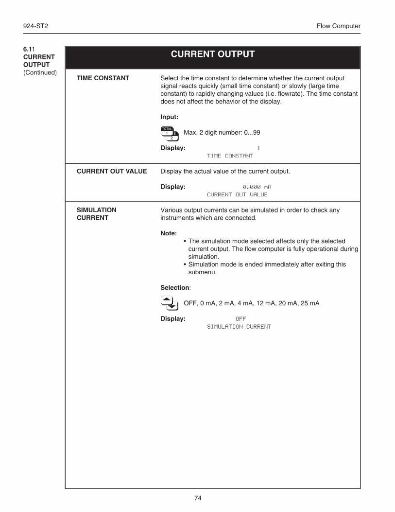
74
924-ST2 Flow Computer
6.11CURRENT OUTPUT(Continued)
CURRENT OUTPUT
Select the time constant to determine whether the current output signal reacts quickly (small time constant) or slowly (large time constant) to rapidly changing values (i.e. fl owrate). The time constant does not affect the behavior of the display.
Input:
Max. 2 digit number: 0...99
Display: 1 TIME CONSTANT
Display the actual value of the current output.
Display: 0.000 mA CURRENT OUT VALUE
Various output currents can be simulated in order to check any instruments which are connected.
Note: • The simulation mode selected affects only the selected
current output. The fl ow computer is fully operational during simulation.
• Simulation mode is ended immediately after exiting this submenu.
Selection:
OFF, 0 mA, 2 mA, 4 mA, 12 mA, 20 mA, 25 mA OFF, 0 mA, 2 mA, 4 mA, 12 mA, 20 mA, 25 mA OFF, 0 mA, 2 mA, 4 mA, 12 mA, 20 mA, 25 mA OFF, 0 mA, 2 mA, 4 mA, 12 mA, 20 mA, 25 mA OFF, 0 mA, 2 mA, 4 mA, 12 mA, 20 mA, 25 mA OFF, 0 mA, 2 mA, 4 mA, 12 mA, 20 mA, 25 mA OFF, 0 mA, 2 mA, 4 mA, 12 mA, 20 mA, 25 mA OFF, 0 mA, 2 mA, 4 mA, 12 mA, 20 mA, 25 mA OFF, 0 mA, 2 mA, 4 mA, 12 mA, 20 mA, 25 mA OFF, 0 mA, 2 mA, 4 mA, 12 mA, 20 mA, 25 mA OFF, 0 mA, 2 mA, 4 mA, 12 mA, 20 mA, 25 mA
Display: OFF SIMULATION CURRENT
TIME CONSTANT
CURRENT OUT VALUE
SIMULATION CURRENT
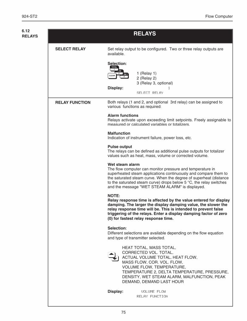
75
924-ST2 Flow Computer
RELAYS6.12RELAYS
Set relay output to be confi gured. Two or three relay outputs are available.
Selection:
1 (Relay 1) 2 (Relay 2) 3 (Relay 3, optional)Display: 1 SELECT RELAY
Both relays (1 and 2, and optional 3rd relay) can be assigned to various functions as required:
Alarm functionsRelays activate upon exceeding limit setpoints. Freely assignable to measured or calculated variables or totalizers.
MalfunctionIndication of instrument failure, power loss, etc.
Pulse outputThe relays can be defi ned as additional pulse outputs for totalizer values such as heat, mass, volume or corrected volume.
Wet steam alarmThe fl ow computer can monitor pressure and temperature in superheated steam applications continuously and compare them to the saturated steam curve. When the degree of superheat (distance to the saturated steam curve) drops below 5 °C, the relay switches and the message "WET STEAM ALARM" is displayed.
NOTE:Relay response time is affected by the value entered for display damping. The larger the display damping value, the slower the relay response time will be. This is intended to prevent false triggering of the relays. Enter a display damping factor of zero (0) for fastest relay response time.
Selection:Different selections are available depending on the fl ow equation and type of transmitter selected.
HEAT TOTAL, MASS TOTAL, CORRECTED VOL. TOTAL, CORRECTED VOL. TOTAL, CORRECTED VOL. TOTAL, CORRECTED VOL. TOTAL, CORRECTED VOL. TOTAL, CORRECTED VOL. TOTAL, CORRECTED VOL. TOTAL, ACTUAL VOLUME TOTAL, HEAT FLOW, ACTUAL VOLUME TOTAL, HEAT FLOW, ACTUAL VOLUME TOTAL, HEAT FLOW, ACTUAL VOLUME TOTAL, HEAT FLOW, ACTUAL VOLUME TOTAL, HEAT FLOW, ACTUAL VOLUME TOTAL, HEAT FLOW, ACTUAL VOLUME TOTAL, HEAT FLOW, ACTUAL VOLUME TOTAL, HEAT FLOW, ACTUAL VOLUME TOTAL, HEAT FLOW, ACTUAL VOLUME TOTAL, HEAT FLOW, ACTUAL VOLUME TOTAL, HEAT FLOW, MASS FLOW, COR. VOL. FLOW, MASS FLOW, COR. VOL. FLOW, MASS FLOW, COR. VOL. FLOW, MASS FLOW, COR. VOL. FLOW, MASS FLOW, COR. VOL. FLOW, VOLUME FLOW, TEMPERATURE, TEMPERATURE 2, DELTA TEMPERATURE, PRESSURE,
DENSITY, WET STEAM ALARM, MALFUNCTION, PEAK DEMAND, DEMAND LAST HOUR
Display: VOLUME FLOW RELAY FUNCTION
SELECT RELAY
RELAY FUNCTION
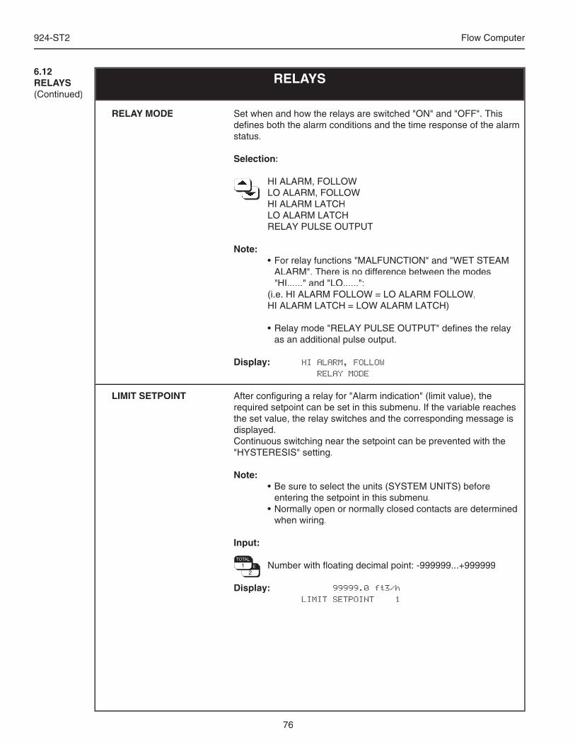
76
924-ST2 Flow Computer
Set when and how the relays are switched "ON" and "OFF". This defi nes both the alarm conditions and the time response of the alarm status.
Selection:
HI ALARM, FOLLOW HI ALARM, FOLLOW HI ALARM, FOLLOW HI ALARM, FOLLOW HI ALARM, FOLLOW HI ALARM, FOLLOW HI ALARM, FOLLOW LO ALARM, FOLLOW LO ALARM, FOLLOW LO ALARM, FOLLOW LO ALARM, FOLLOW LO ALARM, FOLLOW LO ALARM, FOLLOW LO ALARM, FOLLOW LO ALARM, FOLLOW LO ALARM, FOLLOW LO ALARM, FOLLOW LO ALARM, FOLLOW HI ALARM LATCH LO ALARM LATCH RELAY PULSE OUTPUT
Note: • For relay functions "MALFUNCTION" and "WET STEAM
ALARM". There is no difference between the modes "HI......" and "LO......":
(i.e. HI ALARM FOLLOW = LO ALARM FOLLOW, HI ALARM LATCH = LOW ALARM LATCH)
• Relay mode "RELAY PULSE OUTPUT" defi nes the relay as an additional pulse output.
Display: HI ALARM, FOLLOW RELAY MODE
After confi guring a relay for "Alarm indication" (limit value), the required setpoint can be set in this submenu. If the variable reaches the set value, the relay switches and the corresponding message is displayed.Continuous switching near the setpoint can be prevented with the "HYSTERESIS" setting.
Note: • Be sure to select the units (SYSTEM UNITS) before
entering the setpoint in this submenu. • Normally open or normally closed contacts are determined
when wiring.
Input:
Number with fl oating decimal point: -999999...+999999
Display: 99999.0 ft3/h LIMIT SETPOINT 1
RELAY MODE
LIMIT SETPOINT
6.12RELAYS(Continued)
RELAYS
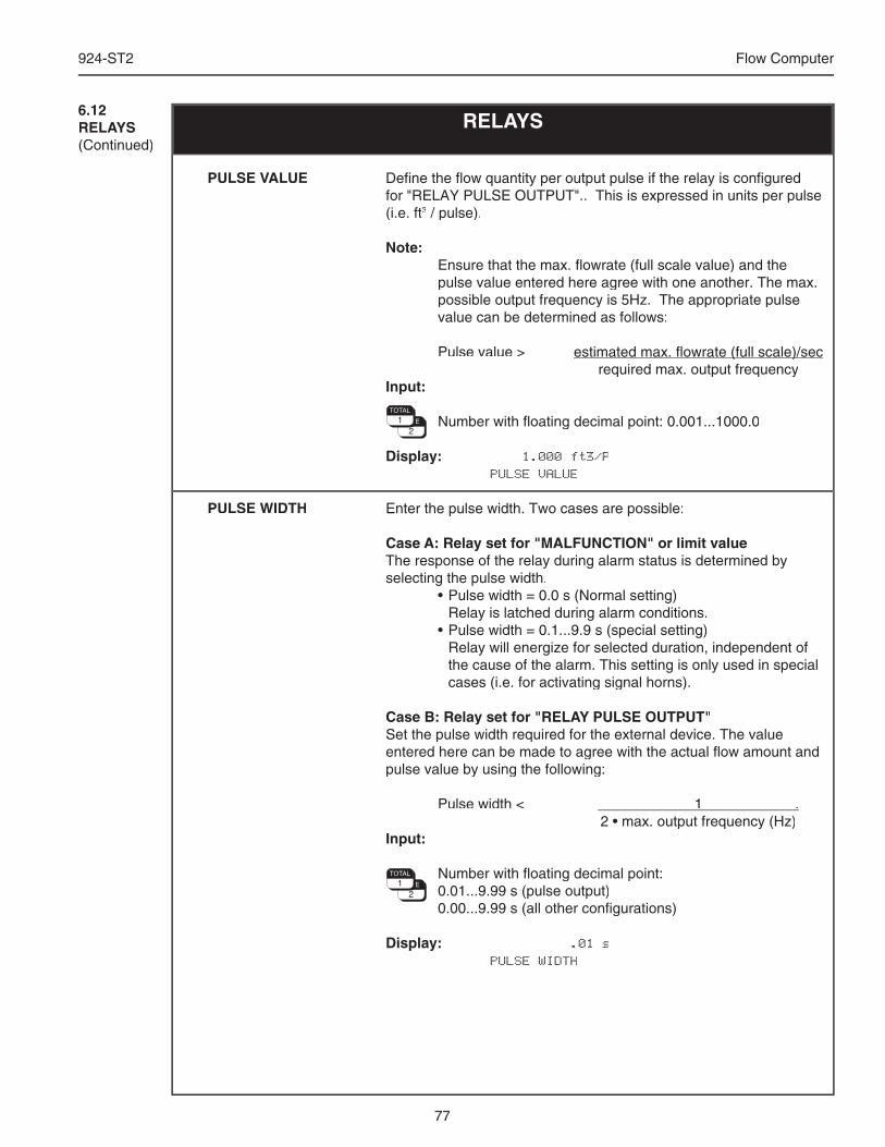
77
924-ST2 Flow Computer
Defi ne the fl ow quantity per output pulse if the relay is confi gured for "RELAY PULSE OUTPUT".. This is expressed in units per pulse (i.e. ft3 / pulse).
Note: Ensure that the max. fl owrate (full scale value) and the
pulse value entered here agree with one another. The max. possible output frequency is 5Hz. The appropriate pulse value can be determined as follows:
Pulse value > estimated max. fl owrate (full scale)/secestimated max. fl owrate (full scale)/sec required max. output frequencyInput:
Number with fl oating decimal point: 0.001...1000.0
Display: 1.000 ft3/P PULSE VALUE
Enter the pulse width. Two cases are possible:
Case A: Relay set for "MALFUNCTION" or limit valueThe response of the relay during alarm status is determined by selecting the pulse width. • Pulse width = 0.0 s (Normal setting) Relay is latched during alarm conditions. • Pulse width = 0.1...9.9 s (special setting) Relay will energize for selected duration, independent of
the cause of the alarm. This setting is only used in special cases (i.e. for activating signal horns).
Case B: Relay set for "RELAY PULSE OUTPUT"Set the pulse width required for the external device. The value entered here can be made to agree with the actual fl ow amount and pulse value by using the following:
Pulse width < 1 . 2 • max. output frequency (Hz)Input:
Number with fl oating decimal point: 0.01...9.99 s (pulse output) 0.00...9.99 s (all other confi gurations)
Display: .01 s PULSE WIDTH
PULSE VALUE
PULSE WIDTH
6.12RELAYS(Continued)
RELAYS
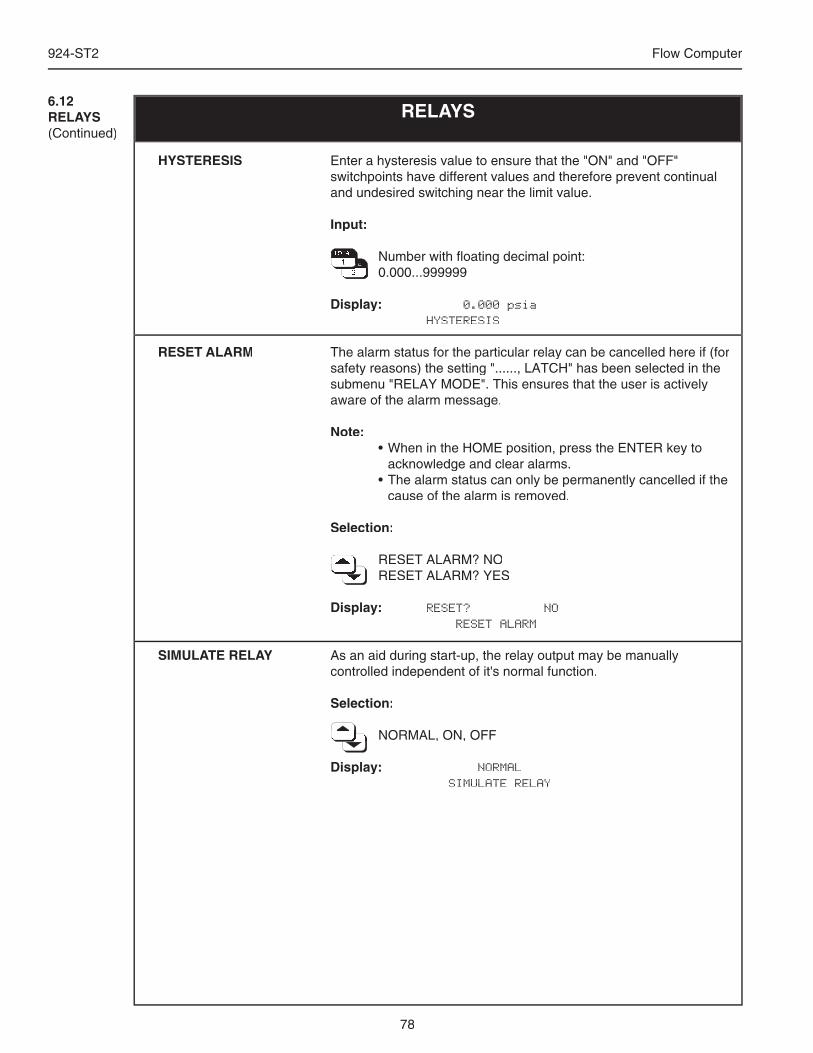
78
924-ST2 Flow Computer
6.12RELAYS(Continued)
RELAYS
Enter a hysteresis value to ensure that the "ON" and "OFF" switchpoints have different values and therefore prevent continual and undesired switching near the limit value.
Input:
Number with fl oating decimal point: Number with fl oating decimal point: Number with fl oating decimal point: Number with fl oating decimal point: Number with fl oating decimal point: Number with fl oating decimal point: Number with fl oating decimal point: Number with fl oating decimal point: Number with fl oating decimal point: Number with fl oating decimal point: Number with fl oating decimal point: Number with fl oating decimal point: Number with fl oating decimal point: Number with fl oating decimal point: Number with fl oating decimal point: Number with fl oating decimal point: Number with fl oating decimal point: Number with fl oating decimal point: 0.000...999999 0.000...999999 0.000...999999 0.000...999999 0.000...999999 0.000...999999 0.000...999999 0.000...999999 0.000...999999 0.000...999999
Display: 0.000 psia HYSTERESIS
The alarm status for the particular relay can be cancelled here if (for safety reasons) the setting "......, LATCH" has been selected in the submenu "RELAY MODE". This ensures that the user is actively aware of the alarm message.
Note: • When in the HOME position, press the ENTER key to
acknowledge and clear alarms. • The alarm status can only be permanently cancelled if the
cause of the alarm is removed.
Selection:
RESET ALARM? NO RESET ALARM? NO RESET ALARM? NO RESET ALARM? NO RESET ALARM? NO RESET ALARM? NO RESET ALARM? NO RESET ALARM? YES RESET ALARM? YES RESET ALARM? YES RESET ALARM? YES RESET ALARM? YES RESET ALARM? YES RESET ALARM? YES RESET ALARM? YES RESET ALARM? YES RESET ALARM? YES RESET ALARM? YES
Display: RESET? NO RESET ALARM
As an aid during start-up, the relay output may be manually controlled independent of it's normal function.
Selection:
NORMAL, ON, OFF NORMAL, ON, OFF NORMAL, ON, OFF NORMAL, ON, OFF NORMAL, ON, OFF NORMAL, ON, OFF NORMAL, ON, OFF NORMAL, ON, OFF NORMAL, ON, OFF NORMAL, ON, OFF NORMAL, ON, OFF
Display: NORMAL SIMULATE RELAY
HYSTERESIS
RESET ALARM
SIMULATE RELAY
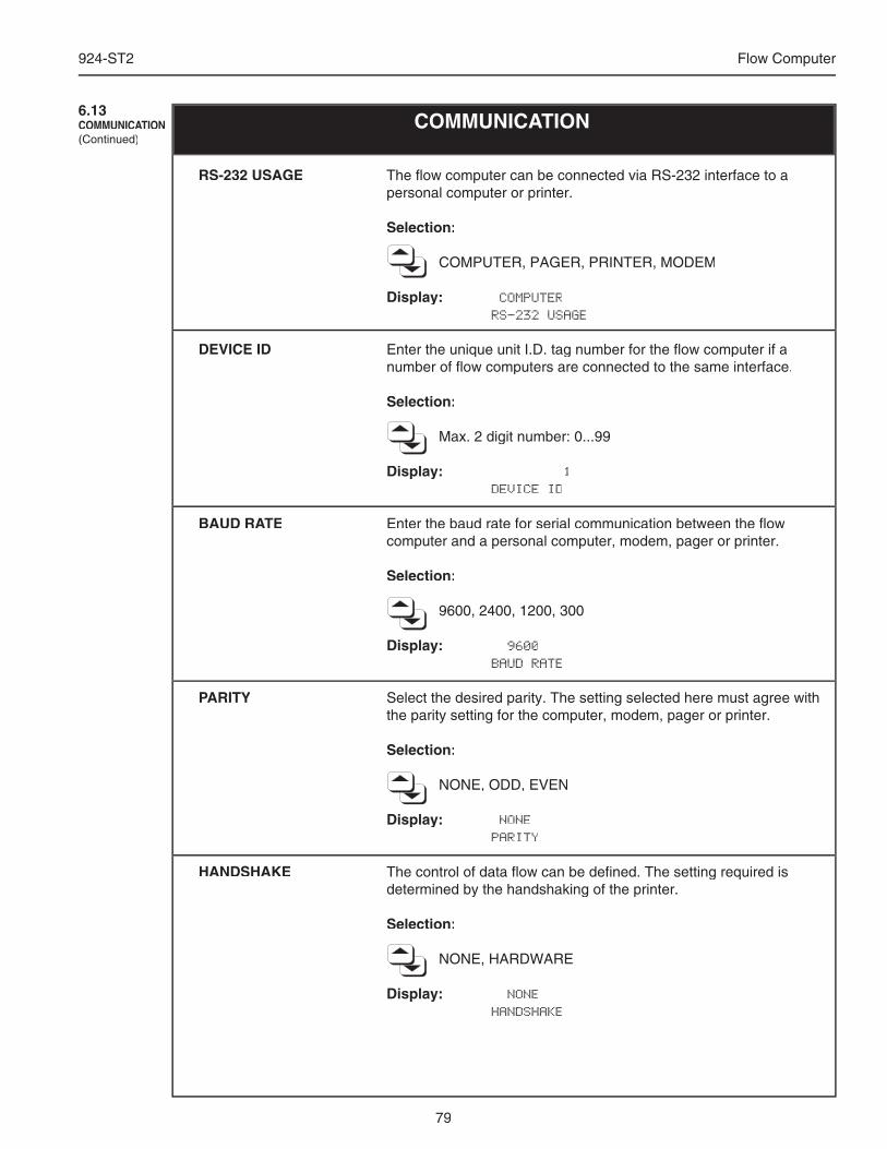
79
924-ST2 Flow Computer
The fl ow computer can be connected via RS-232 interface to a personal computer or printer.
Selection:
COMPUTER, PAGER, PRINTER, MODEM
Display: COMPUTER RS-232 USAGE
Enter the unique unit I.D. tag number for the fl ow computer if a number of fl ow computers are connected to the same interface.
Selection:
Max. 2 digit number: 0...99
Display: 1 DEVICE ID
Enter the baud rate for serial communication between the fl ow computer and a personal computer, modem, pager or printer.
Selection:
9600, 2400, 1200, 300
Display: 9600 BAUD RATE
Select the desired parity. The setting selected here must agree with the parity setting for the computer, modem, pager or printer.
Selection:
NONE, ODD, EVEN
Display: NONE PARITY
The control of data fl ow can be defi ned. The setting required is determined by the handshaking of the printer.
Selection:
NONE, HARDWARE
Display: NONE HANDSHAKE
RS-232 USAGE
DEVICE ID
BAUD RATE
PARITY
HANDSHAKE
COMMUNICATION6.13COMMUNICATION(Continued)
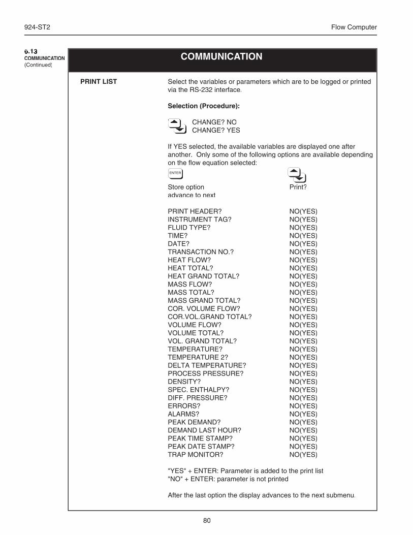
80
924-ST2 Flow Computer
Select the variables or parameters which are to be logged or printed via the RS-232 interface.
Selection (Procedure):
CHANGE? NO CHANGE? NO CHANGE? NO CHANGE? NO CHANGE? NO CHANGE? NO CHANGE? NO CHANGE? NO CHANGE? NO CHANGE? YES CHANGE? YES CHANGE? YES CHANGE? YES CHANGE? YES CHANGE? YES CHANGE? YES CHANGE? YES CHANGE? YES
If YES selected, the available variables are displayed one after another. Only some of the following options are available depending on the fl ow equation selected:
Store option Print?advance to next
PRINT HEADER? NO(YES)INSTRUMENT TAG? NO(YES)FLUID TYPE? NO(YES)TIME? NO(YES)DATE? NO(YES)TRANSACTION NO.? NO(YES)HEAT FLOW? NO(YES)HEAT TOTAL? NO(YES)HEAT GRAND TOTAL? NO(YES)MASS FLOW? NO(YES)MASS TOTAL? NO(YES)MASS GRAND TOTAL? NO(YES)COR. VOLUME FLOW? NO(YES)COR.VOL.GRAND TOTAL? NO(YES)VOLUME FLOW? NO(YES)VOLUME TOTAL? NO(YES)VOL. GRAND TOTAL? NO(YES)TEMPERATURE? NO(YES)TEMPERATURE 2? NO(YES)DELTA TEMPERATURE? NO(YES)PROCESS PRESSURE? NO(YES)DENSITY? NO(YES)SPEC. ENTHALPY? NO(YES)DIFF. PRESSURE? NO(YES)ERRORS? NO(YES)ALARMS? NO(YES)PEAK DEMAND? NO(YES)DEMAND LAST HOUR? NO(YES)PEAK TIME STAMP? NO(YES)PEAK DATE STAMP? NO(YES)TRAP MONITOR? NO(YES)
"YES" + ENTER: Parameter is added to the print list"NO" + ENTER: parameter is not printed
After the last option the display advances to the next submenu.
PRINT LIST
COMMUNICATION6.13COMMUNICATION(Continued)
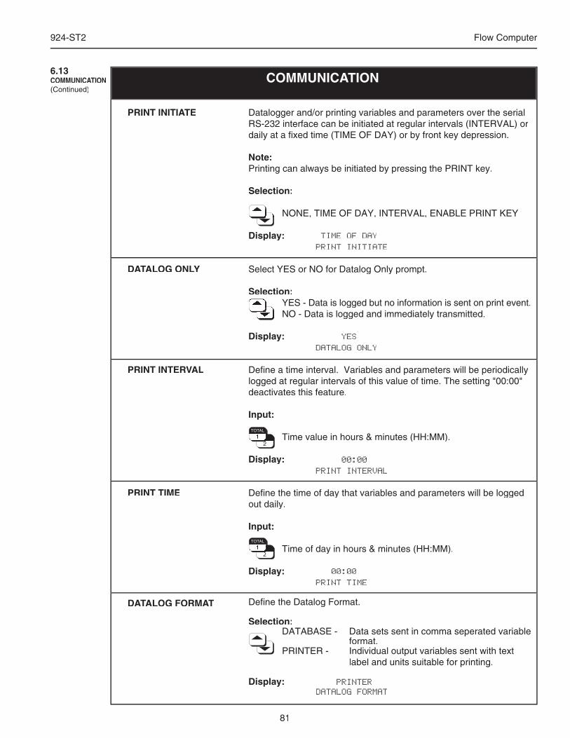
81
924-ST2 Flow Computer
PRINT INITIATE
DATALOG ONLY
PRINT INTERVAL
PRINT TIME
DATALOG FORMAT
COMMUNICATION6.13COMMUNICATION(Continued)
Datalogger and/or printing variables and parameters over the serial RS-232 interface can be initiated at regular intervals (INTERVAL) or daily at a fi xed time (TIME OF DAY) or by front key depression.
Note:Printing can always be initiated by pressing the PRINT key.
Selection:
NONE, TIME OF DAY, INTERVAL, ENABLE PRINT KEY NONE, TIME OF DAY, INTERVAL, ENABLE PRINT KEY NONE, TIME OF DAY, INTERVAL, ENABLE PRINT KEY NONE, TIME OF DAY, INTERVAL, ENABLE PRINT KEY NONE, TIME OF DAY, INTERVAL, ENABLE PRINT KEY NONE, TIME OF DAY, INTERVAL, ENABLE PRINT KEY NONE, TIME OF DAY, INTERVAL, ENABLE PRINT KEY NONE, TIME OF DAY, INTERVAL, ENABLE PRINT KEY NONE, TIME OF DAY, INTERVAL, ENABLE PRINT KEY NONE, TIME OF DAY, INTERVAL, ENABLE PRINT KEY NONE, TIME OF DAY, INTERVAL, ENABLE PRINT KEY
Display: TIME OF DAY PRINT INITIATE
Select YES or NO for Datalog Only prompt.
Selection: YES - Data is logged but no information is sent on print event. YES - Data is logged but no information is sent on print event. YES - Data is logged but no information is sent on print event. YES - Data is logged but no information is sent on print event. YES - Data is logged but no information is sent on print event. YES - Data is logged but no information is sent on print event. YES - Data is logged but no information is sent on print event. YES - Data is logged but no information is sent on print event. YES - Data is logged but no information is sent on print event. NO - Data is logged and immediately transmitted. NO - Data is logged and immediately transmitted. NO - Data is logged and immediately transmitted. NO - Data is logged and immediately transmitted. NO - Data is logged and immediately transmitted. NO - Data is logged and immediately transmitted. NO - Data is logged and immediately transmitted. NO - Data is logged and immediately transmitted. NO - Data is logged and immediately transmitted. NO - Data is logged and immediately transmitted. NO - Data is logged and immediately transmitted.
Display: YES DATALOG ONLY
Defi ne a time interval. Variables and parameters will be periodically logged at regular intervals of this value of time. The setting "00:00" deactivates this feature.
Input:
Time value in hours & minutes (HH:MM). Time value in hours & minutes (HH:MM). Time value in hours & minutes (HH:MM). Time value in hours & minutes (HH:MM). Time value in hours & minutes (HH:MM). Time value in hours & minutes (HH:MM). Time value in hours & minutes (HH:MM). Time value in hours & minutes (HH:MM). Time value in hours & minutes (HH:MM). Time value in hours & minutes (HH:MM). Time value in hours & minutes (HH:MM). Time value in hours & minutes (HH:MM). Time value in hours & minutes (HH:MM). Time value in hours & minutes (HH:MM). Time value in hours & minutes (HH:MM). Time value in hours & minutes (HH:MM).
Display: 00:00 PRINT INTERVAL
Defi ne the time of day that variables and parameters will be logged out daily.
Input:
Time of day in hours & minutes (HH:MM). Time of day in hours & minutes (HH:MM). Time of day in hours & minutes (HH:MM). Time of day in hours & minutes (HH:MM). Time of day in hours & minutes (HH:MM). Time of day in hours & minutes (HH:MM). Time of day in hours & minutes (HH:MM). Time of day in hours & minutes (HH:MM). Time of day in hours & minutes (HH:MM). Time of day in hours & minutes (HH:MM). Time of day in hours & minutes (HH:MM). Time of day in hours & minutes (HH:MM). Time of day in hours & minutes (HH:MM). Time of day in hours & minutes (HH:MM).
Display: 00:00 PRINT TIME
Defi ne the Datalog Format.
Selection:DATABASE - Data sets sent in comma seperated variable
format.PRINTER - Individual output variables sent with text
label and units suitable for printing.
Display: PRINTER DATALOG FORMAT
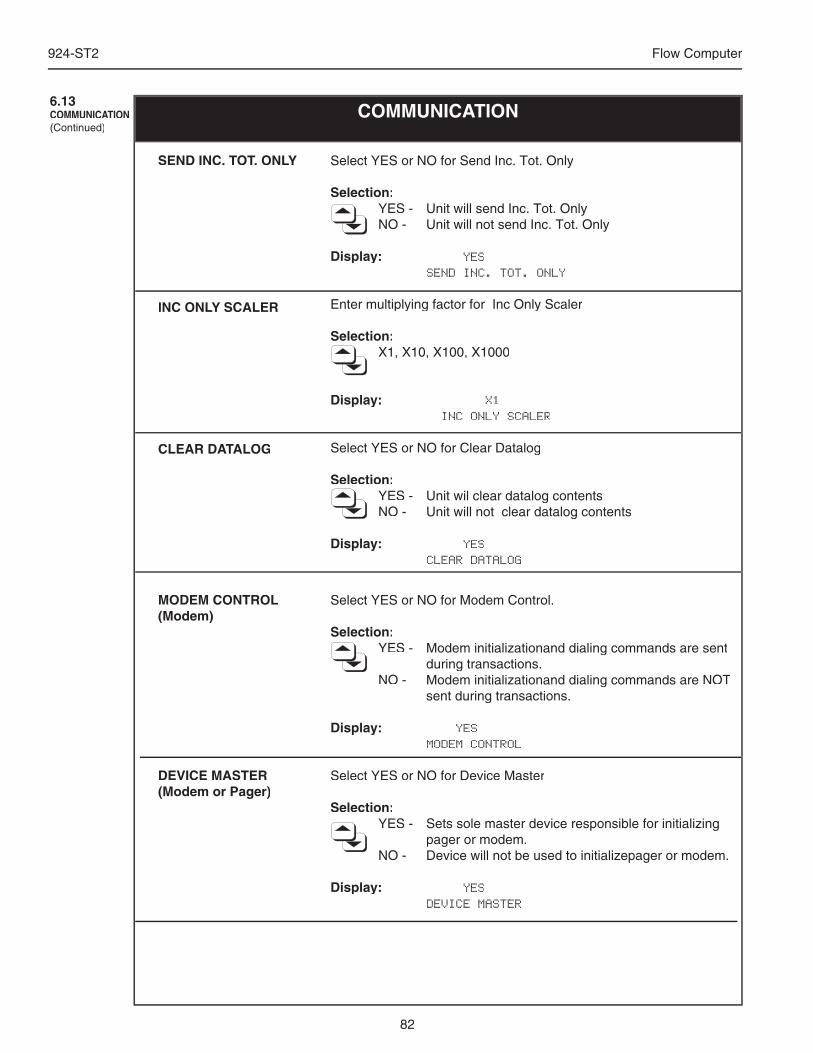
82
924-ST2 Flow Computer
COMMUNICATION6.13COMMUNICATION(Continued)
Select YES or NO for Modem Control.
Selection:YES - Modem initializationand dialing commands are sent
during transactions.NO - Modem initializationand dialing commands are NOT
sent during transactions.
Display: YES MODEM CONTROL
Select YES or NO for Device Master
Selection:YES - Sets sole master device responsible for initializing
pager or modem.NO - Device will not be used to initializepager or modem.
Display: YES DEVICE MASTER
MODEM CONTROL(Modem)
DEVICE MASTER(Modem or Pager)
Select YES or NO for Send Inc. Tot. Only
Selection:YES - Unit will send Inc. Tot. OnlyNO - Unit will not send Inc. Tot. Only
Display: YES SEND INC. TOT. ONLY
Enter multiplying factor for Inc Only Scaler
Selection: X1, X10, X100, X1000
Display: X1 INC ONLY SCALER
Select YES or NO for Clear Datalog
Selection:YES - Unit wil clear datalog contentsNO - Unit will not clear datalog contents
Display: YES CLEAR DATALOG
SEND INC. TOT. ONLY
INC ONLY SCALER
CLEAR DATALOG
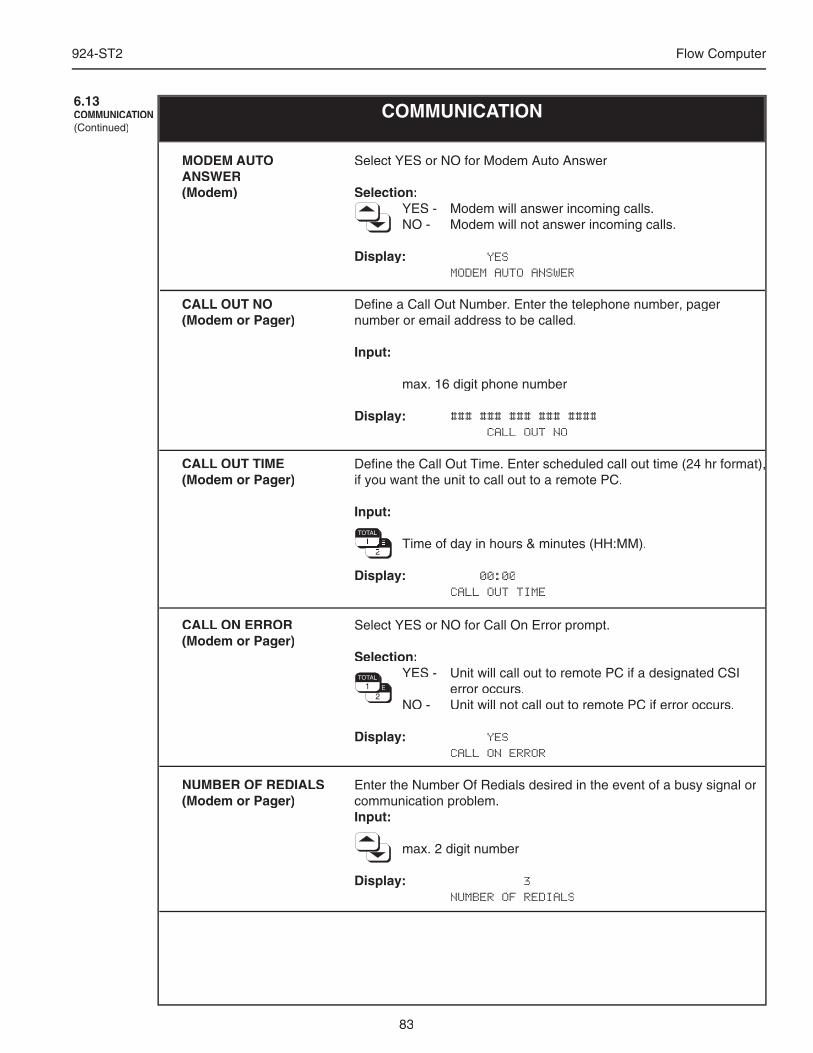
83
924-ST2 Flow Computer
COMMUNICATION6.13COMMUNICATION(Continued)
Enter the Number Of Redials desired in the event of a busy signal or communication problem.Input:
max. 2 digit number
Display: 3 NUMBER OF REDIALS
NUMBER OF REDIALS(Modem or Pager)
Select YES or NO for Call On Error prompt.
Selection:YES - Unit will call out to remote PC if a designated CSI
error occurs.NO - Unit will not call out to remote PC if error occurs.
Display: YES CALL ON ERROR
CALL ON ERROR(Modem or Pager)
Select YES or NO for Modem Auto Answer
Selection:YES - Modem will answer incoming calls.NO - Modem will not answer incoming calls.
Display: YES MODEM AUTO ANSWER
Defi ne a Call Out Number. Enter the telephone number, pager number or email address to be called.
Input:
max. 16 digit phone number
Display: ### ### ### ### #### CALL OUT NO
Defi ne the Call Out Time. Enter scheduled call out time (24 hr format), Defi ne the Call Out Time. Enter scheduled call out time (24 hr format), if you want the unit to call out to a remote PC.
Input:
Time of day in hours & minutes (HH:MM). Time of day in hours & minutes (HH:MM). Time of day in hours & minutes (HH:MM). Time of day in hours & minutes (HH:MM). Time of day in hours & minutes (HH:MM). Time of day in hours & minutes (HH:MM). Time of day in hours & minutes (HH:MM). Time of day in hours & minutes (HH:MM). Time of day in hours & minutes (HH:MM). Time of day in hours & minutes (HH:MM). Time of day in hours & minutes (HH:MM). Time of day in hours & minutes (HH:MM). Time of day in hours & minutes (HH:MM). Time of day in hours & minutes (HH:MM).
Display: 00:00 CALL OUT TIME
MODEM AUTO ANSWER(Modem)
CALL OUT NO(Modem or Pager)
CALL OUT TIME(Modem or Pager)
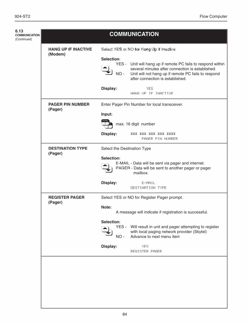
84
924-ST2 Flow Computer
COMMUNICATION6.13COMMUNICATION(Continued)
Enter Pager Pin Number for local transceiver.
Input:
max. 16 digit number
Display: ### ### ### ### #### PAGER PIN NUMBER
Select the Destination Type
Selection:E-MAIL - Data will be sent via pager and internet.PAGER - Data will be sent to another pager or pager
mailbox.
Display: E-MAIL DESTINATION TYPE
Select YES or NO for Register Pager prompt.
Note: A message will indicate if registration is successful.
Selection:YES - Will result in unit and pager attempting to register
with local paging network provider (Skytel)NO - Advance to next menu item
Display: YES REGISTER PAGER
PAGER PIN NUMBER(Pager)
DESTINATION TYPE(Pager)
REGISTER PAGER(Pager)
Select YES or NO for Hang Up If Inactive
Selection:YES - Unit will hang up if remote PC fails to respond within
several minutes after connection is established.NO - Unit will not hang up if remote PC fails to respond
after connection is established.
Display: YES HANG UP IF INACTIVE
HANG UP IF INACTIVE(Modem)
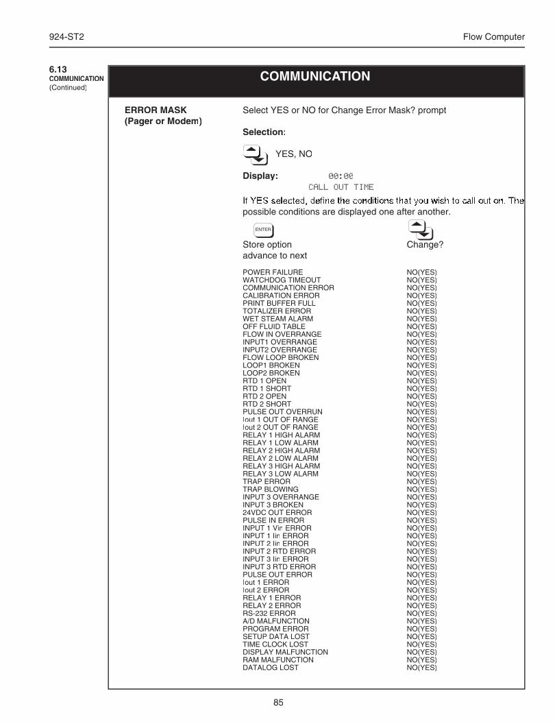
85
924-ST2 Flow Computer
If YES selected, defi ne the conditions that you wish to call out on. The If YES selected, defi ne the conditions that you wish to call out on. The possible conditions are displayed one after another.
Store option Change?advance to next
POWER FAILURE NO(YES)WATCHDOG TIMEOUT NO(YES)COMMUNICATION ERROR NO(YES)CALIBRATION ERROR NO(YES)PRINT BUFFER FULL NO(YES)TOTALIZER ERROR NO(YES)WET STEAM ALARM NO(YES)OFF FLUID TABLE NO(YES)FLOW IN OVERRANGE NO(YES)INPUT1 OVERRANGE NO(YES)INPUT2 OVERRANGE NO(YES)FLOW LOOP BROKEN NO(YES)LOOP1 BROKEN NO(YES)LOOP2 BROKEN NO(YES)RTD 1 OPEN NO(YES)RTD 1 SHORT NO(YES)RTD 2 OPEN NO(YES)RTD 2 SHORT NO(YES)PULSE OUT OVERRUN NO(YES)Iout 1 OUT OF RANGE NO(YES)Iout 2 OUT OF RANGE NO(YES)RELAY 1 HIGH ALARM NO(YES)RELAY 1 LOW ALARM NO(YES)RELAY 2 HIGH ALARM NO(YES)RELAY 2 LOW ALARM NO(YES)RELAY 3 HIGH ALARM NO(YES)RELAY 3 LOW ALARM NO(YES)TRAP ERROR NO(YES)TRAP BLOWING NO(YES)INPUT 3 OVERRANGE NO(YES)INPUT 3 BROKEN NO(YES)24VDC OUT ERROR NO(YES)PULSE IN ERROR NO(YES)INPUT 1 Vin ERROR NO(YES)INPUT 1 Iin ERROR NO(YES)INPUT 2 Iin ERROR NO(YES)INPUT 2 RTD ERROR NO(YES)INPUT 3 Iin ERROR NO(YES)INPUT 3 RTD ERROR NO(YES)PULSE OUT ERROR NO(YES)Iout 1 ERROR NO(YES)Iout 2 ERROR NO(YES)RELAY 1 ERROR NO(YES)RELAY 2 ERROR NO(YES)RS-232 ERROR NO(YES)A/D MALFUNCTION NO(YES)PROGRAM ERROR NO(YES)SETUP DATA LOST NO(YES)TIME CLOCK LOST NO(YES)DISPLAY MALFUNCTION NO(YES)RAM MALFUNCTION NO(YES)DATALOG LOST NO(YES)
Select YES or NO for Change Error Mask? prompt
Selection:
YES, NO YES, NO YES, NO YES, NO YES, NO YES, NO YES, NO YES, NO YES, NO YES, NO YES, NO YES, NO YES, NO
Display: 00:00 CALL OUT TIME
ERROR MASK(Pager or Modem)
COMMUNICATION6.13COMMUNICATION(Continued)
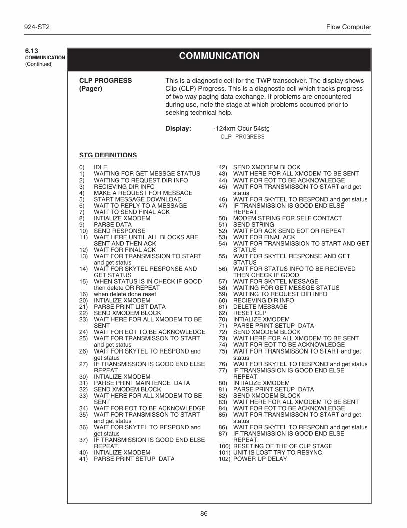
86
924-ST2 Flow Computer
COMMUNICATION6.13COMMUNICATION(Continued)
This is a diagnostic cell for the TWP transceiver. The display shows Clip (CLP) Progress. This is a diagnostic cell which tracks progress of two way paging data exchange. If problems are encountered during use, note the stage at which problems occurred prior to seeking technical help.
Display: -124xm Ocur 54stg CLP PROGRESS
CLP PROGRESS(Pager)
0) IDLE1) WAITING FOR GET MESSGE STATUS2) WAITING TO REQUEST DIR INFO3) RECIEVING DIR INFO4) MAKE A REQUEST FOR MESSAGE5) START MESSAGE DOWNLOAD6) WAIT TO REPLY TO A MESSAGE7) WAIT TO SEND FINAL ACK8) INTIALIZE XMODEM9) PARSE DATA10) SEND RESPONSE11) WAIT HERE UNTIL ALL BLOCKS ARE
SENT AND THEN ACK12) WAIT FOR FINAL ACK13) WAIT FOR TRANSMISSION TO START
and get status14) WAIT FOR SKYTEL RESPONSE AND
GET STATUS15) WHEN STATUS IS IN CHECK IF GOOD
then delete OR REPEAT16) when delete done reset20) INTIALIZE XMODEM21) PARSE PRINT LIST DATA22) SEND XMODEM BLOCK23) WAIT HERE FOR ALL XMODEM TO BE
SENT24) WAIT FOR EOT TO BE ACKNOWLEDGE25) WAIT FOR TRANSMISSON TO START
and get status26) WAIT FOR SKYTEL TO RESPOND and
get status27) IF TRANSMISSION IS GOOD END ELSE
REPEAT.30) INTIALIZE XMODEM31) PARSE PRINT MAINTENCE DATA32) SEND XMODEM BLOCK33) WAIT HERE FOR ALL XMODEM TO BE
SENT34) WAIT FOR EOT TO BE ACKNOWLEDGE35) WAIT FOR TRANSMISSON TO START
and get status36) WAIT FOR SKYTEL TO RESPOND and
get status37) IF TRANSMISSION IS GOOD END ELSE
REPEAT.40) INTIALIZE XMODEM41) PARSE PRINT SETUP DATA
42) SEND XMODEM BLOCK43) WAIT HERE FOR ALL XMODEM TO BE SENT44) WAIT FOR EOT TO BE ACKNOWLEDGE45) WAIT FOR TRANSMISSON TO START and get
status46) WAIT FOR SKYTEL TO RESPOND and get status47) IF TRANSMISSION IS GOOD END ELSE
REPEAT.50) MODEM STRING FOR SELF CONTACT51) SEND STRING52) WAIT FOR ACK SEND EOT OR REPEAT53) WAIT FOR FINAL ACK54) WAIT FOR TRANSMISSION TO START AND GET
STATUS55) WAIT FOR SKYTEL RESPONSE AND GET
STATUS56) WAIT FOR STATUS INFO TO BE RECIEVED
THEN CHECK IF GOOD57) WAIT FOR SKYTEL MESSAGE58) WAITING FOR GET MESSGE STATUS59) WAITING TO REQUEST DIR INFO60) RECIEVING DIR INFO61) DELETE MESSAGE62) RESET CLP70) INTIALIZE XMODEM71) PARSE PRINT SETUP DATA72) SEND XMODEM BLOCK73) WAIT HERE FOR ALL XMODEM TO BE SENT74) WAIT FOR EOT TO BE ACKNOWLEDGE75) WAIT FOR TRANSMISSON TO START and get
status76) WAIT FOR SKYTEL TO RESPOND and get status77) IF TRANSMISSION IS GOOD END ELSE
REPEAT.80) INTIALIZE XMODEM81) PARSE PRINT SETUP DATA82) SEND XMODEM BLOCK83) WAIT HERE FOR ALL XMODEM TO BE SENT84) WAIT FOR EOT TO BE ACKNOWLEDGE85) WAIT FOR TRANSMISSON TO START and get
status86) WAIT FOR SKYTEL TO RESPOND and get status87) IF TRANSMISSION IS GOOD END ELSE
REPEAT.100) RESETING OF THE OF CLP STAGE101) UNIT IS LOST TRY TO RESYNC.102) POWER UP DELAY
STG DEFINITIONS
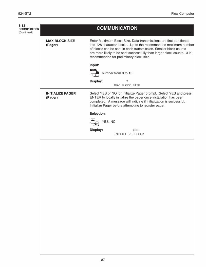
87
924-ST2 Flow Computer
Enter Maximum Block Size. Data transmissions are fi rst partitioned into 128 character blocks. Up to the recommended maximum number into 128 character blocks. Up to the recommended maximum number of blocks can be sent in each transmission. Smaller block counts are more likely to be sent successfully than larger block counts. 3 is recommended for preliminary block size.
Input:
number from 0 to 15 number from 0 to 15 number from 0 to 15 number from 0 to 15 number from 0 to 15 number from 0 to 15 number from 0 to 15 number from 0 to 15 number from 0 to 15 number from 0 to 15 number from 0 to 15 number from 0 to 15 number from 0 to 15 number from 0 to 15
Display: 3 MAX BLOCK SIZE
Select YES or NO for Initialize Pager prompt. Select YES and press ENTER to locally initialize the pager once installation has been completed. A message will indicate if initialization is successful. Initialize Pager before attempting to register pager.
Selection:
YES, NO YES, NO YES, NO YES, NO YES, NO YES, NO YES, NO YES, NO YES, NO YES, NO YES, NO
Display: YES INITIALIZE PAGER
MAX BLOCK SIZE(Pager)
INITIALIZE PAGER(Pager)
COMMUNICATION6.13COMMUNICATION(Continued)
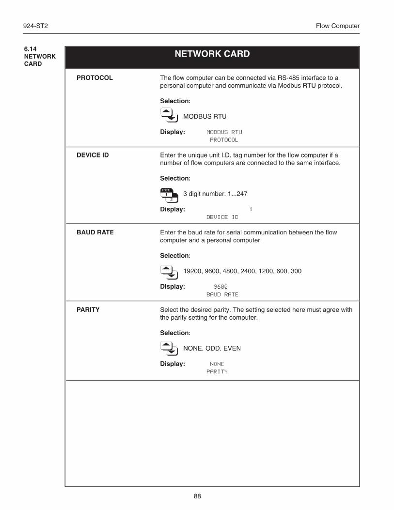
88
924-ST2 Flow Computer
The fl ow computer can be connected via RS-485 interface to a personal computer and communicate via Modbus RTU protocol.
Selection:
MODBUS RTU MODBUS RTU MODBUS RTU MODBUS RTU MODBUS RTU MODBUS RTU MODBUS RTU MODBUS RTU MODBUS RTU MODBUS RTU MODBUS RTU
Display: MODBUS RTU PROTOCOL
Enter the unique unit I.D. tag number for the fl ow computer if a number of fl ow computers are connected to the same interface.
Selection:
3 digit number: 1...247 3 digit number: 1...247 3 digit number: 1...247 3 digit number: 1...247 3 digit number: 1...247 3 digit number: 1...247 3 digit number: 1...247 3 digit number: 1...247 3 digit number: 1...247 3 digit number: 1...247 3 digit number: 1...247 3 digit number: 1...247 3 digit number: 1...247 3 digit number: 1...247 3 digit number: 1...247 3 digit number: 1...247 3 digit number: 1...247 3 digit number: 1...247
Display: 1 DEVICE ID
Enter the baud rate for serial communication between the fl ow computer and a personal computer.
Selection:
19200, 9600, 4800, 2400, 1200, 600, 300
Display: 9600 BAUD RATE
Select the desired parity. The setting selected here must agree with the parity setting for the computer.
Selection:
NONE, ODD, EVEN
Display: NONE PARITY
PROTOCOL
DEVICE ID
BAUD RATE
PARITY
NETWORK CARD6.14NETWORKCARD
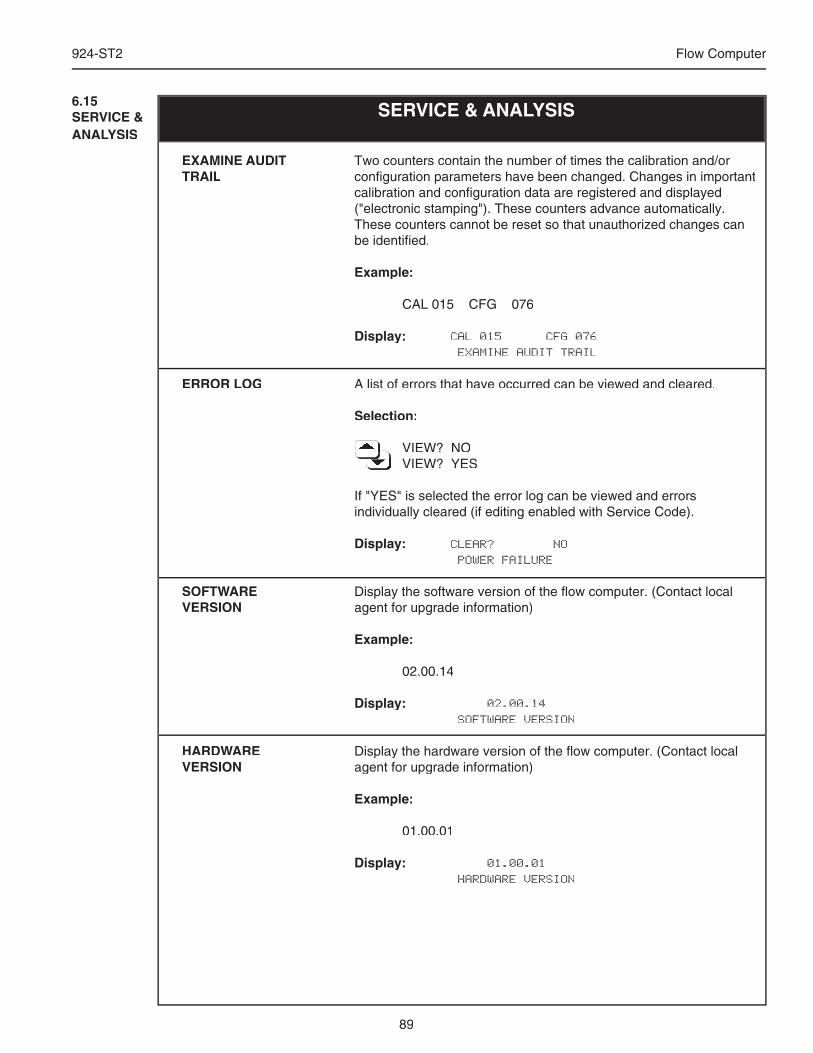
89
924-ST2 Flow Computer
Two counters contain the number of times the calibration and/or confi guration parameters have been changed. Changes in important calibration and confi guration data are registered and displayed ("electronic stamping"). These counters advance automatically.These counters cannot be reset so that unauthorized changes can be identifi ed.
Example:
CAL 015 CFG 076
Display: CAL 015 CFG 076 EXAMINE AUDIT TRAIL
A list of errors that have occurred can be viewed and cleared.
Selection:
VIEW? NO VIEW? NO VIEW? NO VIEW? NO VIEW? NO VIEW? NO VIEW? NO VIEW? NO VIEW? NO VIEW? YES VIEW? YES VIEW? YES VIEW? YES VIEW? YES VIEW? YES VIEW? YES VIEW? YES VIEW? YES
If "YES" is selected the error log can be viewed and errors individually cleared (if editing enabled with Service Code).
Display: CLEAR? NO POWER FAILURE
Display the software version of the fl ow computer. (Contact local agent for upgrade information)
Example:
02.00.14
Display: 02.00.14 SOFTWARE VERSION
Display the hardware version of the fl ow computer. (Contact local agent for upgrade information)
Example:
01.00.01
Display: 01.00.01 HARDWARE VERSION
EXAMINE AUDIT TRAIL
ERROR LOG
SOFTWARE VERSION
HARDWARE VERSION
SERVICE & ANALYSIS6.15SERVICE & ANALYSIS
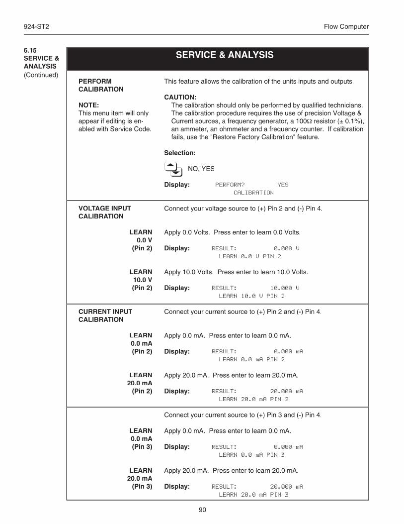
90
924-ST2 Flow Computer
SERVICE & ANALYSIS6.15SERVICE & ANALYSIS(Continued)
This feature allows the calibration of the units inputs and outputs.
CAUTION:The calibration should only be performed by qualifi ed technicians. The calibration procedure requires the use of precision Voltage & Current sources, a frequency generator, a 100Ω resistor (± 0.1%), an ammeter, an ohmmeter and a frequency counter. If calibration fails, use the "Restore Factory Calibration" feature.
Selection:
NO, YES
Display: PERFORM? YES CALIBRATION
Connect your voltage source to (+) Pin 2 and (-) Pin 4.
Apply 0.0 Volts. Press enter to learn 0.0 Volts.
Display: RESULT: 0.000 V LEARN 0.0 V PIN 2
Apply 10.0 Volts. Press enter to learn 10.0 Volts.
Display: RESULT: 10.000 V LEARN 10.0 V PIN 2
Connect your current source to (+) Pin 2 and (-) Pin 4.
Apply 0.0 mA. Press enter to learn 0.0 mA.
Display: RESULT: 0.000 mA LEARN 0.0 mA PIN 2
Apply 20.0 mA. Press enter to learn 20.0 mA.
Display: RESULT: 20.000 mA LEARN 20.0 mA PIN 2
Connect your current source to (+) Pin 3 and (-) Pin 4.
Apply 0.0 mA. Press enter to learn 0.0 mA.
Display: RESULT: 0.000 mA LEARN 0.0 mA PIN 3
Apply 20.0 mA. Press enter to learn 20.0 mA.
Display: RESULT: 20.000 mA LEARN 20.0 mA PIN 3
PERFORM CALIBRATION
NOTE: This menu item will only appear if editing is en-abled with Service Code.
VOLTAGE INPUTCALIBRATION
LEARN 0.0 V
(Pin 2)
LEARN 10.0 V(Pin 2)
CURRENT INPUT CALIBRATION
LEARN 0.0 mA (Pin 2)
LEARN 20.0 mA
(Pin 2)
LEARN 0.0 mA (Pin 3)
LEARN 20.0 mA
(Pin 3)
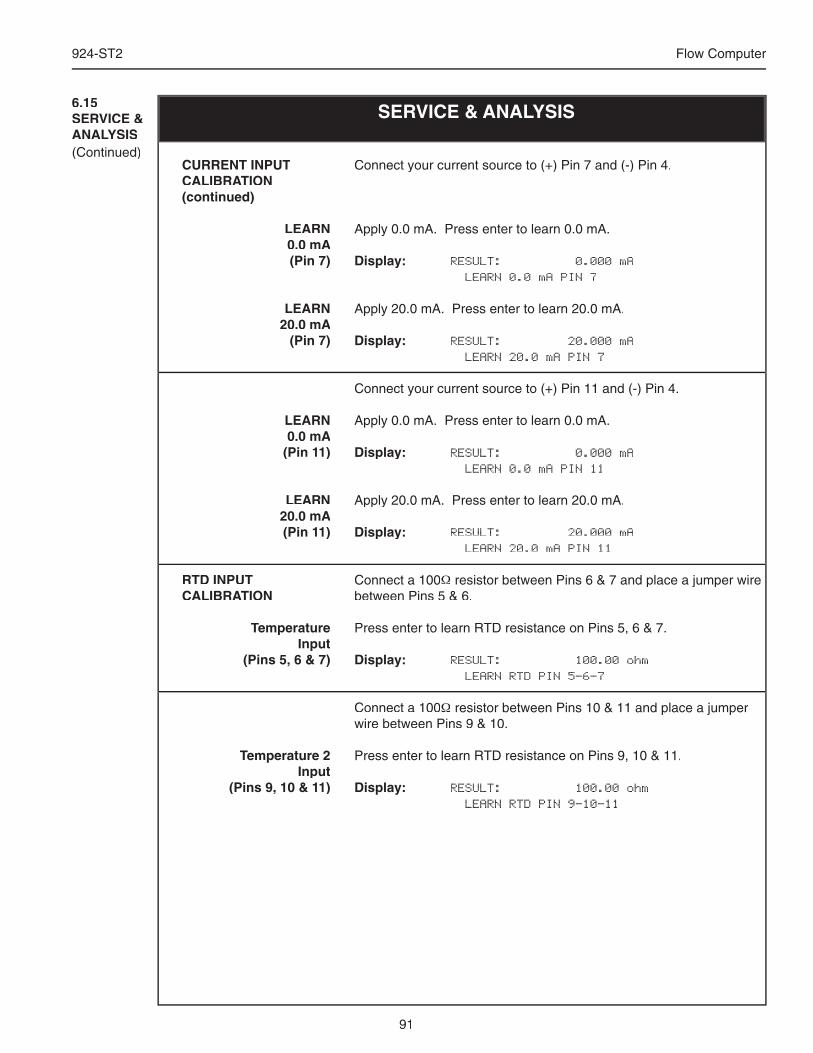
91
924-ST2 Flow Computer
SERVICE & ANALYSIS6.15SERVICE & ANALYSIS(Continued)
Connect your current source to (+) Pin 7 and (-) Pin 4.
Apply 0.0 mA. Press enter to learn 0.0 mA.
Display: RESULT: 0.000 mA LEARN 0.0 mA PIN 7
Apply 20.0 mA. Press enter to learn 20.0 mA.
Display: RESULT: 20.000 mA LEARN 20.0 mA PIN 7
Connect your current source to (+) Pin 11 and (-) Pin 4.
Apply 0.0 mA. Press enter to learn 0.0 mA.
Display: RESULT: 0.000 mA LEARN 0.0 mA PIN 11
Apply 20.0 mA. Press enter to learn 20.0 mA.
Display: RESULT: 20.000 mA LEARN 20.0 mA PIN 11
Connect a 100Ω resistor between Pins 6 & 7 and place a jumper wire between Pins 5 & 6.
Press enter to learn RTD resistance on Pins 5, 6 & 7.
Display: RESULT: 100.00 ohm LEARN RTD PIN 5-6-7
Connect a 100Ω resistor between Pins 10 & 11 and place a jumper wire between Pins 9 & 10.
Press enter to learn RTD resistance on Pins 9, 10 & 11.
Display: RESULT: 100.00 ohm LEARN RTD PIN 9-10-11
CURRENT INPUT CALIBRATION (continued)
LEARN 0.0 mA (Pin 7)
LEARN 20.0 mA
(Pin 7)
LEARN 0.0 mA
(Pin 11)
LEARN 20.0 mA (Pin 11)
RTD INPUT CALIBRATION
TemperatureInput
(Pins 5, 6 & 7)
Temperature 2Input
(Pins 9, 10 & 11)
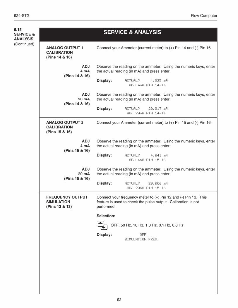
92
924-ST2 Flow Computer
SERVICE & ANALYSIS6.15SERVICE & ANALYSIS(Continued)
Connect your Ammeter (current meter) to (+) Pin 14 and (-) Pin 16.
Observe the reading on the ammeter. Using the numeric keys, enter the actual reading (in mA) and press enter.
Display: ACTUAL? 4.025 mA ADJ 4mA PIN 14-16
Observe the reading on the ammeter. Using the numeric keys, enter the actual reading (in mA) and press enter.
Display: ACTUAL? 20.017 mA ADJ 20mA PIN 14-16
Connect your Ammeter (current meter) to (+) Pin 15 and (-) Pin 16.
Observe the reading on the ammeter. Using the numeric keys, enter the actual reading (in mA) and press enter.
Display: ACTUAL? 4.041 mA ADJ 4mA PIN 15-16
Observe the reading on the ammeter. Using the numeric keys, enter the actual reading (in mA) and press enter.
Display: ACTUAL? 20.006 mA ADJ 20mA PIN 15-16
Connect your frequency meter to (+) Pin 12 and (-) Pin 13. This feature is used to check the pulse output. Calibration is not performed.
Selection:
OFF, 50 Hz, 10 Hz, 1.0 Hz, 0.1 Hz, 0.0 Hz
Display: OFF SIMULATION FREQ.
ANALOG OUTPUT 1CALIBRATION (Pins 14 & 16)
ADJ 4 mA
(Pins 14 & 16)
ADJ 20 mA
(Pins 14 & 16)
ANALOG OUTPUT 2CALIBRATION (Pins 15 & 16)
ADJ 4 mA
(Pins 15 & 16)
ADJ 20 mA
(Pins 15 & 16)
FREQUENCY OUTPUT SIMULATION(Pins 12 & 13)
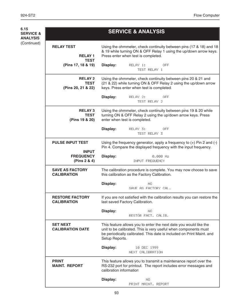
93
924-ST2 Flow Computer
SERVICE & ANALYSIS6.15SERVICE & ANALYSIS(Continued)
Using the ohmmeter, check continuity between pins (17 & 18) and 18 & 19 while turning ON & OFF Relay 1 using the up/down arrow keys. Press enter when test is completed.
Display: RELAY 1: OFF TEST RELAY 1
Using the ohmmeter, check continuity between pins 20 & 21 and (21 & 22) while turning ON & OFF Relay 2 using the up/down arrow keys. Press enter when test is completed.
Display: RELAY 2: OFF TEST RELAY 2
Using the ohmmeter, check continuity between pins 19 & 20 while turning ON & OFF Relay 2 using the up/down arrow keys. Press enter when test is completed.
Display: RELAY 3: OFF TEST RELAY 3
Using the frequency generator, apply a frequency to (+) Pin 2 and (-) Pin 4. Compare the displayed frequency with the input frequency.
Display: 0.000 Hz INPUT FREQUENCY
The calibration procedure is complete. You may now choose to save this calibration as the Factory Calibration.
Display: NO SAVE AS FACTORY CAL.
If you are not satisfi ed with the calibration results you can restore the last saved Factory Calibration.
Display: NO RESTOR FACT. CALIB.
This feature allows you to enter the next date you would like the unit to be calibrated. This is very useful when components must be periodically calibrated. This date is included on Print Maint. and Setup Reports.
Display: 10 DEC 1999 NEXT CALIBRATION
This feature allows you to transmit a maintenance report over the RS-232 port for printout. The report includes error messages and calibration information
Display: NO PRINT MAINT. REPORT
RELAY TEST
RELAY 1TEST
(Pins 17, 18 & 19)
RELAY 2TEST
(Pins 20, 21 & 22)
RELAY 3TEST
(Pins 19 & 20)
PULSE INPUT TEST
INPUTFREQUENCY
(Pins 2 & 4)
SAVE AS FACTORY CALIBRATION
RESTORE FACTORY CALIBRATION
SET NEXT CALIBRATION DATE
PRINT MAINT. REPORT
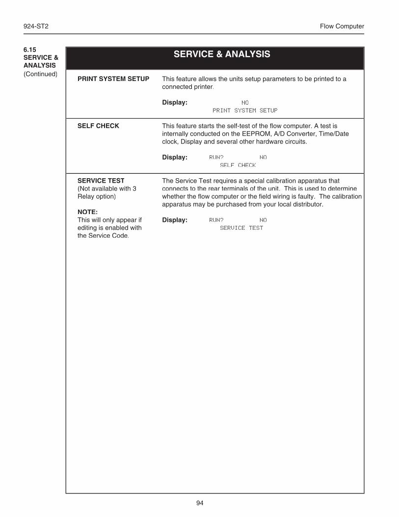
94
924-ST2 Flow Computer
This feature allows the units setup parameters to be printed to a connected printer.
Display: NO PRINT SYSTEM SETUP
This feature starts the self-test of the fl ow computer. A test is internally conducted on the EEPROM, A/D Converter, Time/Date clock, Display and several other hardware circuits.
Display: RUN? NO SELF CHECK
The Service Test requires a special calibration apparatus that connects to the rear terminals of the unit. This is used to determine whether the fl ow computer or the fi eld wiring is faulty. The calibration apparatus may be purchased from your local distributor.
Display: RUN? NO SERVICE TEST
PRINT SYSTEM SETUP
SELF CHECK
SERVICE TEST(Not available with 3 Relay option)
NOTE:This will only appear if editing is enabled with the Service Code.
SERVICE & ANALYSIS6.15SERVICE & ANALYSIS(Continued)
95
924-ST2 Flow Computer
7. Principle Of Operation
7.1 General:
The 924-ST2 Flow Computer uses several internal calculations to compute the compen-sated fl ow based on specifi c data input. Several computations are performed to arrive at the uncompensated fl ow, temperature, pressure, density and viscosity. This information is then used to compute the Corrected Volume Flow, Mass Flow or Heat Flow.
7.2 Square Law Flowmeter Considerations:
Head class fl owmeters are supplied by the manufacturers with a 4-20 mA output span which is already in fl ow units. The 924-ST2 permits the user to enter this fl owmeter information directly. However, closely associated with this information is the density that was assumed during fl owmeter calibration. This information must also be input if the user is to obtain maximum accuracy.
It is assumed that the user has the printout from a standardized sizing program for the particular device he will be using. Such standardized printouts list all the necessary information which the user will then be prompted for.
Several specialized fl ow equations are listed that are not intended for the standard unit but to be offered to appropriate OEMs or as special order items. These are desig-nated by a “†”.
Note concerning Fluid InformationThe user will be prompted for Fluid Information during the setup of the instrument. SeeAppendix A for the properties of several common fl uids.
7.3 Flow Equations:
Flow Input Computation:
Linear Input Flow = [% input span • (fl ow FS - fl ow low scale)]+ fl ow low scale
Square Law without External SQRT ExtractorSquare Law without External SQRT Extractor delta P = [(% input span) • ( fl ow FS - fl ow low scale)] + fl ow low scale
Square Law with External SQRT ExtractorSquare Law with External SQRT Extractor delta P = [(% input span)2 • ( fl ow FS - fl ow low scale)] + fl ow low scale
NOTE: For stacked differential pressure option, the appropriate input sensor signal is used in calculations at all times to maximize accuracy.
General Operation
Square Law Flow-meterConsiderations
Flow Equations
7.3.1 Flow InputComputation
96
924-ST2 Flow Computer
Pressure Input:
General Case Pf = [% input span • (Pres full scale - Pres low scale ] + Pres low scale
Gauge CaseGauge Case Pf = Pf + Barometric
Manual Case or In Event of Fault Pf = Pressure Default Value
Temperature Computation:
General Case Tf = [% input span • (Temp full scale - Temp low scale ] + Temp low scale
RTD Case Tf = f ( measured input resistance)
Manual Case or In Event of FaultFaultF Tf = Temperature Default Value
Delta Temp CaseDelta Temp Case Delta Temp = T2 - T1 Flowmeter location = cold Delta Temp = T1 - T2 Flowmeter location = hot
Density Computation:
Water Case density_water = density (Tf)
Liquid CaseLiquid Case density = reference density • ( 1 - Therm.Exp.Coef. •( Tf - Tref))
2
Steam Case density = 1/ specifi c volume(Tf, Pf)
Gas Case Pf (Tref + 273.15) Zref
density = reference density • • • Pref (Tf + 273.15) Zf
NOTE: For Natural Gas:
is determined by NX-19 when this selection is supplied and selected.
NOTE: Therm.Exp.Coef is (x 10-6)
density = reference density • • • density = reference density • • •
7.3.2 Pressure Computation
7.3.3Temperature Computation
7.3.4Density/ViscosityComputation
Zref
Zf
97
924-ST2 Flow Computer
7.3.4Density/ViscosityComputation(continued)
7.3.5 Corrected Volume FlowComputation
Viscosity (cP) Computation:
Liquid CaseLiquid Case Liquid Case Liquid Case NOTE: B viscosity (in cP) cP viscosity = A • exp cP viscosity = A • exp
Viscosity cS = B viscosity (in cP)
Viscosity cS = B viscosity (in cP)
fl owing density ( Tf + 459.67) density of water @ 4°C
Gas Case
cP viscosity = A • ( Tf + 459.67)B
Steam Case
cP viscosity = f(Tf, Pf)
Corrected Volume Flow Computation:
Liquid Case Liquid Case std. volume fl ow = volume fl ow • ( 1 - Therm.Exp.Coef. •( Tf - Tref))2
Gas Case std. volume fl ow = volume fl ow • Pf . • (T(Tref + 273.15) + 273.15) • Zref . Pref ( Tf + 273.15) Zf
NOTE: For Natural Gas:
Zref . Zf
is determined by NX-19 when this selection is supplied and selected.
Natural Gas NX-19 Equation: The NX-19 (1963) natural gas state equations are widely used in custody transfer applications. Over most normal measurement ranges, 500 to 5000 psia (3.5 to 10.4 MPa) and -10 to 100°F (-23 to 38°C), the NX-19 equation will compute the gas compressibility factor to within 0.2% of the values computed by the newer AGA-8 state equa-tion. The ranges over which the NX-19 equation applies are: Pressure PGPGP To 5000 psig (10.34 MPa gauge)G To 5000 psig (10.34 MPa gauge)G
Temperature TfTfT -40 to 240°F (-40 to 116°C)f -40 to 240°F (-40 to 116°C)f
Specifi c Gravity G 0.554 to 1.0G 0.554 to 1.0G CO2 and N2 0 to 15%
Our Flow Computer uses the Specifi c Gravity method to fi rst obtain the adjusted temperature and pressure before entering the state equation. This method calculates the adjusted pres-sure and temperature from the mole fractions of carbon dioxide and nitrogen as
Padj = 156.47 PG . psig 160.8 – 7.22 Gg + 100XC02XC02X – 39.2XN2XN2X
Where XC02 and XC02 and X XN2XN2X are the mole fractions of carbon dioxide and nitrogen, respectively. The adjusted temperature is defi ned by
Tadj = 226.29 (T226.29 (TF + 460) + 460) °F 99.15 + 211.9 Gg – 100XC02XC02X – 168.1XN2XN2X
B viscosity (in cP)
( fl owing density( fl owing density ( Tf + 459.67) density of water @ 4°C( ( Tf + 459.67) density of water @ 4°C)
98
924-ST2 Flow Computer
After calculating the adjusted pressure and temperature, the mixture’s pressure and tempera-ture correlations parameters are calculated bycorrelations parameters are calculated bycorrelations parameters P = P = P P adj + 14.7 T = T = T T adj . 1000 500The compressibility factor is then calculated by fi rst determining
m = 0.0330378 m = 0.0330378 m T -2 – 0.0221323T -3 + 0.0161353T -5
n = (0.265827T -2 + 0.0457697T -4 – 0.133185T -1)m -1
B = 3 – mn2mn2mn 9mp2mp2mp b = 9n – n – n 2mn3 – E .
54mp2mp2mp 2mp2mp2mpD = [D = [D b + (b + (b b 2 + B 3 B 3 B )0.5]1/3
Where E is a function of the pressure E is a function of the pressure E p and temperature T correlation parameters. The equations for T correlation parameters. The equations for TE are given in the following table for the designated regions. The following compressibility E are given in the following table for the designated regions. The following compressibility E ZfZfZ is deter-mined by
ZfZfZ = 1 . B / D – D + n / 3p
NX-19 Natural Gas Regions and E Equations
Ranges P T E 0 to 2 1.09 to 1.40 E1
0 to 1.3 0.84 to 1.09 E2E2E 1.3 to 2.0 0.88 to 1.09 E3E3E 1.3 to 2.0 0.84 to 0.88 E4E4E 2.0 to 5.0 0.84 to 0.88 E5E5E 2.0 to 5.0 0.88 to 1.09 E6E6E 2.0 to 5.0 1.09 to 1.32 E7E7E 2.0 to 5.0 1.32 to 1.40 E8E8E
Ta = T – 1.09 Tb Tb T = 1.09 – TE1 = 1 – 0.00075p2.3p2.3p exp (-20Ta) – 0.0011Ta
0.5p2p2p (2.17 + 1.4Ta0.5 – p)2
E2 E2 E = 1 – 0.00075p2.3p2.3p [2 – exp (-20TbTbT )] – 1.317TbTbT 4p(1.69 – p2p2p )E3 E3 E = 1 – 0.00075p2.3p2.3p [2 – exp (-20TbTbT )] + 0.455(200TbTbT 6 – 0.03249TbTbT
+ 2.0167TbTbT 2 – 18.028TbTbT 3 + 42.844TbTbT 4)(p – 1.3)[1.69(2)1.25 – p2 p2 p ]E4 E4 E = 1 – 0.00075p2.3p2.3p [2 – exp (-20TbTbT )] + 0.455(200TbTbT 6 – 0.03249TbTbT
+ 2.0167TbTbT 2 – 18.028TbTbT 3 + 42.844TbTbT 4)(p – 1.3)[1.69(2)p – 1.3)[1.69(2)p 1.25 + 80(0.88 – t)2 – p2 p2 p ]E5 E5 E = E4E4E –X E6 X E6 X E = E3E3E –X E7 X E7 X E = E1 –X E8 X E8 X E = E7E7E –X1X1XX = A (T – 2) + T – 2) + T A1(p – 2)2 + A2(p – 2)p – 2)p 3 + A3(p – 2)p – 2)p 4
X1X1X = (p – 1.32)2(p –2)[3 – 1.483(p –2)[3 – 1.483(p p – 2) – 0.1(p –2)p –2)p 2 + 0.0833(p –2)3]A = 1.7172 – 2.33123T – 1.56796T2T2T + 3.47644T3T3T – 1.28603T4T4TA1 = 0.016299 – 0.028094T – 0.48782T2 T2 T – 0.78221T3T3T + 0.27839T4T4TA2 = –0.35978 + 0.51419T + 0.165453T + 0.165453T T2T2T – 0.52216T3 + 0.19687T4
A3 = 0.075255 – 0.10573T – 0.058598T – 0.058598T T2T2T + 0.14416T3T3T – 0.054533T4T4T
When NX-19 is used for custody transfer applications, the base compressibility factor is calculated by:
Zb Zb Z = b = b (1 + 0.00132 )-2
T (
T (
3.25
7.3.5 Corrected Volume FlowComputation(continued)
Mass Flow Computations:
mass fl ow = volume fl ow • density
Combustion Heat Flow Computations:
combustion heat fl ow = mass fl ow • combustion heating value
7.3.6Mass FlowComputation
7.3.7Comb. Heat FlowComputation
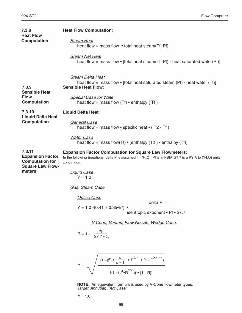
99
924-ST2 Flow Computer
∆p27.7 • p f
R = 1 –
κ − 11 −β4β4β ) •(κ
• R2/κ• (1 - R
(κ−1R
(κ−1R
)/κ)
[(1 −(β •4 R )) • (1 - R)]2/R )2/R )
κY =
= 1.0Y
Sensible Heat Flow:
Special Case for WaterSpecial Case for Water heat fl ow = mass fl ow (Tf) • enthalpy ( Tf )
Liquid Delta Heat:
General Case heat fl ow = mass fl ow • specifi c heat • ( T2 - Tf )
Water Case heat fl ow = mass fl ow(Tf) • [enthalpy (T2 ) - enthalpy (Tf)]
Expansion Factor Computation for Square Law Flowmeters:In the following Equations, delta P is assumed in ("H2O), Pf is in PSIA, 27.7 is a PSIA to ("H2O) units conversion.
Liquid CaseLiquid Case Y = 1.0
Gas, Steam CaseGas, Steam Case
Orifi ce Case delta P Y = 1.0 -(0.41 + 0.35•B4) • isentropic exponent • Pf • 27.7
V-Cone, Venturi, Flow Nozzle, Wedge Case:V-Cone, Venturi, Flow Nozzle, Wedge Case:
NOTE: An equivalent formula is used by V-Cone fl owmeter types. An equivalent formula is used by V-Cone fl owmeter types.Target, Annubar, Pitot Case:Target, Annubar, Pitot Case:
An equivalent formula is used by V-Cone fl owmeter types.Target, Annubar, Pitot Case:
An equivalent formula is used by V-Cone fl owmeter types.
7.3.9Sensible Heat FlowComputation
7.3.10Liquid Delta HeatComputation
7.3.11Expansion Factor Computation for Square Law Flow-meters
Heat Flow Computation:
Steam Heat heat fl ow = mass fl ow • total heat steam(Tf, Pf)
Steam Net Heat heat fl ow = mass fl ow • [total heat steam(Tf, Pf) - heat saturated water(Pf)]
Steam Delta Heat heat fl ow = mass fl ow • [total heat saturated steam (Pf) - heat water (Tf)]
7.3.8Heat FlowComputation
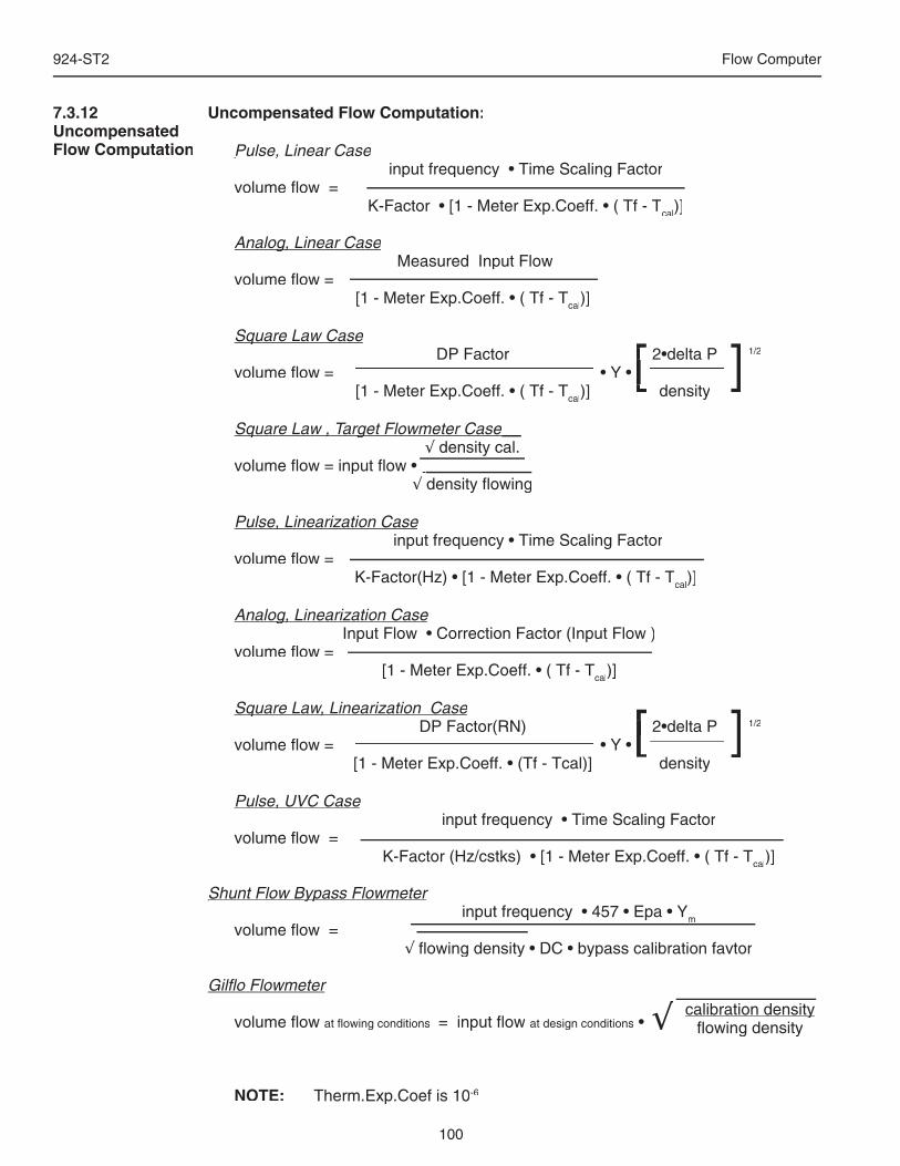
100
924-ST2 Flow Computer
Uncompensated Flow Computation:
Pulse, Linear CasePulse, Linear Case input frequency • Time Scaling Factor volume fl ow = K-Factor • [1 - Meter Exp.Coeff. • ( Tf - Tcal)]
Analog, Linear CaseAnalog, Linear Case Analog, Linear Case Analog, Linear Case Measured Input Flow volume fl ow = [1 - Meter Exp.Coeff. • ( Tf - Tcal)]
Square Law CaseSquare Law Case DP Factor 2•delta P 1/2
volume fl ow = • Y • [1 - Meter Exp.Coeff. • ( Tf - Tcal)] density
Square Law , Target Flowmeter CaseSquare Law , Target Flowmeter Case√ density cal. √ density cal. √
volume fl ow = input fl ow • √ density fl owing√ density fl owing√
Pulse, Linearization CasePulse, Linearization Case input frequency • Time Scaling Factor volume fl ow = K-Factor(Hz) • [1 - Meter Exp.Coeff. • ( Tf - Tcal)]
Analog, Linearization CaseAnalog, Linearization Case Input Flow • Correction Factor (Input Flow ) volume fl ow = [1 - Meter Exp.Coeff. • ( Tf - Tcal)]
Square Law, Linearization CaseSquare Law, Linearization Case DP Factor(RN) 2•delta P 1/2
volume fl ow = • Y • [1 - Meter Exp.Coeff. • (Tf - Tcal)] density
Pulse, UVC CasePulse, UVC Case input frequency • Time Scaling Factor volume fl ow = K-Factor (Hz/cstks) • [1 - Meter Exp.Coeff. • ( Tf - Tcal)]
Shunt Flow Bypass FlowmeterShunt Flow Bypass Flowmeter input frequency • 457 • Epa • Ym volume fl ow = √ fl owing density • DC • bypass calibration favtor √ fl owing density • DC • bypass calibration favtor √
Gilfl o Flowmeter volume fl ow at fl owing conditions = input fl ow at design conditions •
NOTE: Therm.Exp.Coef is 10-6
[ ] DP Factor 2•delta P [ ] DP Factor 2•delta P
)] density[ ]
)] density volume fl ow = • Y • [ ]
[ ] DP Factor(RN) 2•delta P [ ] DP Factor(RN) 2•delta P
[1 - Meter Exp.Coeff. • (Tf - Tcal)] density[ ]
[1 - Meter Exp.Coeff. • (Tf - Tcal)] density volume fl ow = • Y • [ ]
7.3.12Uncompensated Flow Computation
volume fl ow = input fl ow •
Square Law , Target Flowmeter CaseSquare Law , Target Flowmeter Case
volume fl ow = input fl ow •
calibration densitycalibration densityfl owing density√
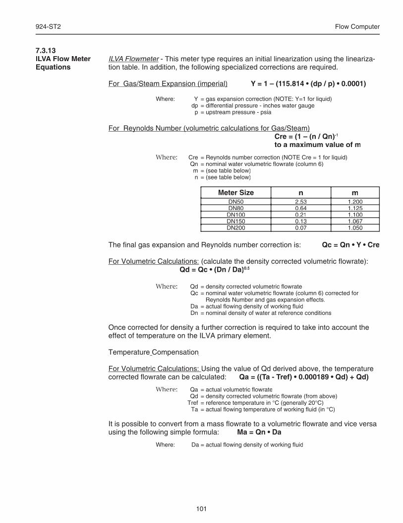
101
924-ST2 Flow Computer
ILVA FlowmeterILVA FlowmeterILVA - This meter type requires an initial linearization using the lineariza- Flowmeter - This meter type requires an initial linearization using the lineariza- Flowmetertion table. In addition, the following specialized corrections are required.
For Gas/Steam Expansion (imperial)For Gas/Steam Expansion (imperial) Y = 1 – (115.814 • (dp / p) • 0.0001) Where: Y = gas expansion correction (NOTE: Y=1 for liquid) dp = differential pressure - inches water gauge p = upstream pressure - psia
For Reynolds Number (volumetric calculations for Gas/Steam)For Reynolds Number (volumetric calculations for Gas/Steam) Cre = (1 – (n / Qn)-1 to a maximum value of m Where: Cre = Reynolds number correction (NOTE Cre = 1 for liquid) Qn = nominal water volumetric fl owrate (column 6) m = (see table below) n = (see table below)
Meter Size n mDN50 2.53 1.200DN80 0.64 1.125
DN100 0.21 1.100DN150 0.13 1.067DN200 0.07 1.050
The fi nal gas expansion and Reynolds number correction is: Qc = Qn • Y • Cre
For Volumetric Calculations: (calculate the density corrected volumetric fl owrate): Qd = Qc • (Dn / Da)0.5
Where: Qd = density corrected volumetric fl owrate Qc = nominal water volumetric fl owrate (column 6) corrected for Reynolds Number and gas expansion effects. Da = actual fl owing density of working fl uid Dn = nominal density of water at reference conditions
Once corrected for density a further correction is required to take into account the effect of temperature on the ILVA primary element.
Temperature Temperature CompensationCompensation
For Volumetric Calculations: Using the value of Qd derived above, the temperature corrected fl owrate can be calculated: Qa = ((Ta - Tref) • 0.000189 • Qd) + Qd) Where: Qa = actual volumetric fl owrate Qd = density corrected volumetric fl owrate (from above) Tref = reference temperature in °C (generally 20°C) Ta = actual fl owing temperature of working fl uid (in °C)
It is possible to convert from a mass fl owrate to a volumetric fl owrate and vice versa using the following simple formula: Ma = Qn • Da Where: Da = actual fl owing density of working fl uid
7.3.13ILVA Flow Meter Equations
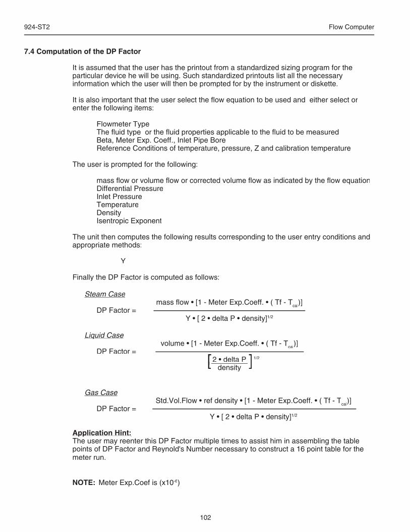
102
924-ST2 Flow Computer
7.4 Computation of the DP Factor
It is assumed that the user has the printout from a standardized sizing program for the particular device he will be using. Such standardized printouts list all the necessary information which the user will then be prompted for by the instrument or diskette.
It is also important that the user select the fl ow equation to be used and either select or enter the following items:
Flowmeter Type The fl uid type or the fl uid properties applicable to the fl uid to be measured Beta, Meter Exp. Coeff., Inlet Pipe Bore Reference Conditions of temperature, pressure, Z and calibration temperature
The user is prompted for the following:
mass fl ow or volume fl ow or corrected volume fl ow as indicated by the fl ow equation Differential Pressure Inlet Pressure Temperature Density Isentropic Exponent
The unit then computes the following results corresponding to the user entry conditions and appropriate methods:
Y
Finally the DP Factor is computed as follows:
Steam Case mass fl ow • [1 - Meter Exp.Coeff. • ( Tf - Tcal)] DP Factor = Y • [ 2 • delta P • density]1/2
Liquid CaseLiquid Case volume • [1 - Meter Exp.Coeff. • ( Tf - Tcal)] DP Factor = 2 • delta P 1/2
density
Gas Case Std.Vol.Flow • ref density • [1 - Meter Exp.Coeff. • ( Tf - Tcal)] DP Factor = Y • [ 2 • delta P • density]1/2
Application Hint:Application Hint:The user may reenter this DP Factor multiple times to assist him in assembling the table points of DP Factor and Reynold's Number necessary to construct a 16 point table for the meter run.
NOTE: Meter Exp.Coef is (x10-6)
[ ] 2 • delta P [ ] 2 • delta P density[ ] density[ ]
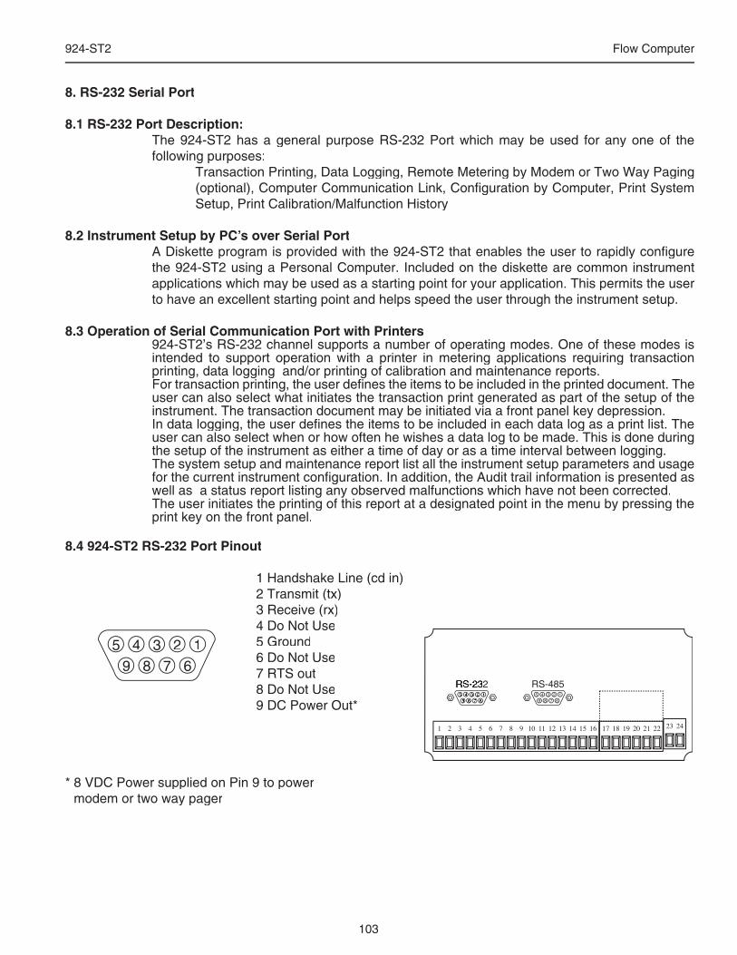
103
924-ST2 Flow Computer
8. RS-232 Serial Port
8.1 RS-232 Port Description:The 924-ST2 has a general purpose RS-232 Port which may be used for any one of the following purposes:
Transaction Printing, Data Logging, Remote Metering by Modem or Two Way Paging (optional), Computer Communication Link, Confi guration by Computer, Print System Setup, Print Calibration/Malfunction History
8.2 Instrument Setup by PC’s over Serial PortA Diskette program is provided with the 924-ST2 that enables the user to rapidly confi gure the 924-ST2 using a Personal Computer. Included on the diskette are common instrument applications which may be used as a starting point for your application. This permits the user to have an excellent starting point and helps speed the user through the instrument setup.
8.3 Operation of Serial Communication Port with Printers 924-ST2’s RS-232 channel supports a number of operating modes. One of these modes is intended to support operation with a printer in metering applications requiring transaction printing, data logging and/or printing of calibration and maintenance reports. For transaction printing, the user defi nes the items to be included in the printed document. The user can also select what initiates the transaction print generated as part of the setup of the instrument. The transaction document may be initiated via a front panel key depression.In data logging, the user defi nes the items to be included in each data log as a print list. The user can also select when or how often he wishes a data log to be made. This is done during the setup of the instrument as either a time of day or as a time interval between logging.The system setup and maintenance report list all the instrument setup parameters and usage for the current instrument confi guration. In addition, the Audit trail information is presented as well as a status report listing any observed malfunctions which have not been corrected.The user initiates the printing of this report at a designated point in the menu by pressing the print key on the front panel.
8.4 924-ST2 RS-232 Port Pinout
1 Handshake Line (cd in)2 Transmit (tx)3 Receive (rx)4 Do Not Use5 Ground6 Do Not Use7 RTS out8 Do Not Use9 DC Power Out*
* 8 VDC Power supplied on Pin 9 to power modem or two way pager
123456789
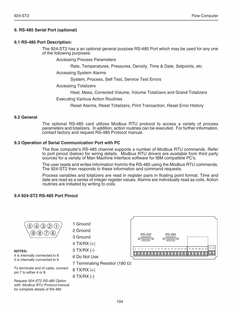
104
924-ST2 Flow Computer
9. RS-485 Serial Port (optional)
9.1 RS-485 Port Description:
The 924-ST2 has a an optional general purpose RS-485 Port which may be used for any one of the following purposes:
Accessing Process Parameters
Rate, Temperatures, Pressures, Density, Time & Date, Setpoints, etc.
Accessing System Alarms
System, Process, Self Test, Service Test Errors
Accessing Totalizers
Heat, Mass, Corrected Volume, Volume Totalizers and Grand Totalizers
Executing Various Action Routines
Reset Alarms, Reset Totalizers, Print Transaction, Reset Error History
9.2 General
The optional RS-485 card utilizes Modbus RTU protocol to access a variety of process parameters and totalizers. In addition, action routines can be executed. For further information, contact factory and request RS-485 Protocol manual.
9.3 Operation of Serial Communication Port with PC
The fl ow computer's RS-485 channel supports a number of Modbus RTU commands. Refer to port pinout (below) for wiring details. Modbus RTU drivers are available from third party sources for a variety of Man Machine Interface software for IBM compatible PC's.
The user reads and writes information from/to the RS-485 using the Modbus RTU commands. The 924-ST2 then responds to these information and command requests.
Process variables and totalizers are read in register pairs in fl oating point format. Time and date are read as a series of integer register values. Alarms are individually read as coils. Action routines are initiated by writing to coils.
9.4 924-ST2 RS-485 Port Pinout
123456789
1 Ground
2 Ground
3 Ground
4 TX/RX (+)
5 TX/RX (-)
6 Do Not Use
7 Terminating Resistor (180 Ω)
8 TX/RX (+)
9 TX/RX (-)
NOTES:4 is internally connected to 85 is internally connected to 9
To terminate end of cable, connect pin 7 to either 4 or 8.
Request 924-ST2 RS-485 Option with Modbus RTU Protocol manual with Modbus RTU Protocol manual with Modbus RTU Protocolfor complete details of RS-485
105
924-ST2 Flow Computer
10. Flow Computer Setup SoftwareThe 924-ST2 setup program provides for confi guring, monitoring and controlling a 924-ST2 unit.Sample applications are stored in disk fi les. The setup program calls these Templates. You can store the setup from the program’s memory to either the 924-ST2 (Downloading the fi le) Downloading the fi le) Downloadingor to a disk fi le (Saving the fi le) for later usage. Similarly you can load the setup in program Saving the fi le) for later usage. Similarly you can load the setup in program Savingmemory from either a disk fi le (Opening a fi le) or from the 924-ST2 unit (Uploading a fi le).loading a fi le).loadingThe program can monitor outputs from the unit while it is running. The program can reset alarms and totalizers.The peak demand may be reset when the option is supplied.For assistance there are mini-helps at the bottom of each screen in the program. There is also context sensitive help available for each screen accessible by pressing the F1 key.
10.1 System Requirements:IBM PC or compatible with 386 or higher class microprocessor4 MB RAM3 MB free disk spaceVGA or higher color monitor at 640 x 480Microsoft® Windows™ 3.1 or 3.11 or Windows 95/98™ or higher® Windows™ 3.1 or 3.11 or Windows 95/98™ or higher®
Communication Port - RS-232RS-232 Cable (customer supplied)
10.2 Cable and Wiring Requirements:The serial communication port on your PC is either a 25 pin or 9 pin connector. No cabling is supplied with the setup software. A cable must be purchased separately or made by the user. It is recommended to purchase a serial cable which matches the available communication port on you PC and a 9 pin male connection for the 924-ST2 serial port.
10.3 Installation for Windows™ 3.1 or 3.11The Setup Software includes an installation program which copies the software to your hard drive.Insert Setup Disk 1 in a fl oppy drive.In the Program Manager, click File, and then select Run.
NOTE: For Windows 95™ Click the Start button, select Run and proceed as follows:
Type the fl oppy drive letter followed by a colon (:) and a backslash (\), and the word setup. For Example: a:\setupFollow the instructions on your screen.
10.4 Using the Flow Computer Setup SoftwareThe setup software window consists of several menu “Tabs”. Each tab is organized into groups containing various confi guration and/or monitoring functions. To view the tab windows, simply click on the tab. The previous tab window will be hidden as the new tab window is brought to the foreground.
Caution: It is required that the 924-ST2 unit which is being confi gured be kept in the operating mode while using the setup diskette. If not, uncertainty exists as to what information will be retained when the session is concluded.
10.5 File Tab
106
924-ST2 Flow Computer
The File Tab has three sections. Any of the options on this tab can also be accessed from the File submenu.The Template Section provides for opening and saving templates. The Save and Save and Save Save As Save As Save Asbuttons provide the standard Windows functionality for dealing with fi les. The Open button is used to open existing templates.
The Open option allows for creating custom templates using the existing template in memory as the starting point. Assign a new name for this template. The template will be saved under this new name.
A typical scenario using the setup program would be the following: • Open up a predefi ned template from the supplied list • Choose ‘Save As’ to save this to a new fi le name • Proceed to customize the template by making any changes that are needed • Save the template to disk (if you want to reuse this template) • Download the template to an attached unit.The Communications with 924-ST2 Section allows the user to upload the setup from the unit or download the program’s current template to the unit.The Print (report) Section allows the user to:
1. Confi gure the current Windows printer through the Select Printer option.2. Print a Maintenance Report through the PC's printer using the Print
Maintenance option.3. Print the current setup through the PC's printer using Print Setup option.
10.6 Setup TabThe Setup tab is where the majority of the 924-ST2 instrument setup modifi cations are done. The Setup tab is divided into fi ve sections. System Section: Parameters, Display, Units Input Section: Flow, Fluid, Compensation Inputs Output Section: Pulse, Currents Relay Section: Relays
Other Settings Section: Administration, Communication, PrintingNOTE: Many setup items are enabled or disabled depending on previous setup
selections, It is important to work your way through the above list in the order shown. Be sure to verify your selections when you are through programming to insure that no settings were changed automatically.
107
924-ST2 Flow Computer
10.7 View TabThe View Tab screen allows for viewing selected group items on the PC in a similar format to that shown on the unit display. Data from the following groups can be viewed in the List of Values section: Process Parameters (i.e. rate, temperature) Totalizers (i.e. total, grand total) Input Signals Analog Output Error Status 924-ST2 Software Version InformationThe setup software assumes the current setup has been uploaded from the fl ow computer into the PC. It is important that the setup program and the 924-ST2 unit are using the same setup information at all times or the data will be inconsistent. It is best to upload or download the setup before using this feature to synchronize the setups.
Error LogData from the error logger is viewed in a separate Error Log section on the screen.To start the viewer, fi rst check the boxes of items to view and then click the start button. The data will appear in the appropriate sections and will be continuously updated. The refresh rate is dependent on the number of items that are being viewed and the baud rate of the connection. Data in the List of Values section can be collapsed by clicking on the ‘minus’ sign in front of the group title. The data can be expanded by clicking on the ‘plus’ sign in front of the group title. If a group is collapsed and data in the group changes on refresh, the group will automatically expand. Data in the Error Log section does not expand or collapse. Changing the view items requires stopping the current viewing, checking the new selections and then restarting the viewer. If communication errors occur while reading data from the 924-ST2 device, the word ‘Error’ will appear in place of the actual value. If the connection to the 924-ST2 is lost, the viewer will time out with a message saying the device is not responding.The viewer will attempt to communicate with the 924-ST2 device matching the device ID set in the communications screen. If you are having trouble establishing communication, compare settings for the PC and the fl ow computer. Also verify the connections between the PC and fl ow computer.
10.8 Misc. TabThis tab has three sections: Tools, Actions and Options.The tools section contains various system administration activities such as creating/modifying the initial sign-on screen or create print headers.
The Actions section is used to send commands to the 924-ST2 unit. Reset Totalizers, Reset Alarms, Simulations, Self Check, Reset Peak Demand (if equipped)
The Options section has the following selections:Language Translations, Network Card Confi gurationAdditional capabilities may be provided in the future.
108
924-ST2 Flow Computer
11. Glossary of Terms
Access Code A numeric password which is entered by a user attempting to gain entry to change setup parameters.
AGA-3 A empirical fl ow equation applicable to orifi ce and several other square law fl owmeters.
AGA-5 A gas fl ow equation for computing the combustion heat fl ow from measured volume fl ow, temperature and pressure as well as
stored gas properties.
AGA-7 A gas fl ow equation for pulse producing, volumetric fl owmeters which computes the equivalent fl ow at reference conditions
from the measurements made at fl owing line conditions.
Assign Usage A menu selection during the setup of the instrument which selects the intended usage for the input/output.
Barometric Pressure An entry of the average, local atmospheric pressure at the altitude or elevation of the installation. (typically 14.696 psia)
Beta A important geometric ratio for a square law fl owmeters.
Calibration An order sequence of adjustments which must be performed in order for the equipment to operate properly.
Calibration Temperature The temperature at which a fl ow sensor was calibrated on a test fl uid.
Combustion Heat The energy released by a fl uid fuel during combustion .
Default A value to be assumed for manual inputs or in the event of a failure in a input sensor.
Display Damping An averaging fi lter constant used to smooth out display bounce.
DP Factor A scaling constant for a square law fl owmeter.
Error Log A historical record which captures errors which have occurred.
Flow Equation A recognized relationship between the process parameters for fl ow, temperature, pressure and density used in fl ow
measurements.
Galvanic Isolation Input and or output functions which do not share a conductive ground or common connection between them.
Gas Cor. Vol Eq. An equation where the corrected volume fl ow of gas at STP is computer from measured volume fl ow, temperature and
pressure as well as stored gas properties.
Gas Comb. Heat Eq. An equation where the combustion heat fl ow of gas is computer from measured volume fl ow, temperature and pressure as
well as stored gas properties.
Gas Mass Eq. An equation where the mass fl ow of gas is computer from measured volume fl ow, temperature and pressure as well as stored
gas properties.
Flowing Z-Factor The mean Z-Factor under fl owing conditions of temperature and pressure for a specifi c gas.
109
924-ST2 Flow Computer
Full Scale The value of the process variable at the full scale or maximum input signal.
Inlet Pipe Bore The internal pipe diameter upstream of the fl ow measurement element.
Isentropic Exponent A property of a gas or vapor utilized in orifi ce meter calculations.
K-Factor The calibration constant for a pulse producing fl owmeter expressed in pulses per unit volume
Linear A fl ow measurement device where the output signal is proportional to fl ow.
Linear 16 Pt. A mathematical approximation to a nonlinear device where by a correction factor or K-Factor table as a function of input signal
is utilized to eliminate fl owmeter nonlinearity.
Low Flow Cutoff The value of input signal below which fl ow rate may be assumed to be 0 and at which totalization will cease.
Low Scale The value of the process variable at the zero input signal.
Manual An entry value to be used as a fi xed condition in a equation
Meter Exp. Coef. A coeffi cient in an equation which may be used to correct for changes in fl owmeter housing dimensioned changes with
temperature.
Mole % The % composition of an individual gas in a gas mixture.
NX-19 A series of equations used to compute the compressibility of natural gas as a function of specifi c gravity, temperature,
pressure and gas composition.
Protocol An agreed upon method of information exchange.
Print Initiate A user specifi ed condition which must be satisfi ed for a transaction document to be printed.
Pulse Type A menu selectable equivalent pulse output stage. Pulse Value An output scaling factor defi ning the equivalent amount of fl ow total represented by 1 output pulse.
Ref. Z-Factor The Z-Factor for a gas at reference conditions of temperature and pressure.
Ref. Density The density of a fl uid at reference conditions of temperature and pressure.
Relay Function The assigned usage for a relay output.
Relay Mode The user’s desired operating mode for the relay. Examples: follow, latch, timed pulse, above setpoint, below setpoint
Safe State The state of an instrument's outputs which will occur during a power down state. The state the instrument assumes when the
computations are paused.
11. Glossary of Terms (Continued)
110
924-ST2 Flow Computer
Scroll List The user’s desired display list which can be presented on the two list display on Line 1 and/or L2 when the SCROLL key is
depressed.
Self Check A diagnostic sequence of steps a unit performs to verify it’s operational readiness to perform it’s intended function.
Service Test A diagnostic sequence requiring specialized test apparatus to function to verify system readiness.
Setpoint An alarm trip point.
Simulation A special operating mode for an output feature which enables a service personnel to manually exercise the output during
installation or trouble shooting operations.
Square Law Flowmeters Types of measurement devices which measure differential pressure across a known geometry to make a fl ow measurement.
SQR LAW (Square Law w/o SQRT) A square law fl ow measurement device equipped with a pressure transmitter with out a integral square root extractor.
SQR LAW-LIN (Square Law w/ SQRT) A square law fl ow measurement device equipped with a pressure transmitter with integral square root extraction.
SQR Law 16PT (Square Law 16pt) A mathematical approximation to a square law device where the discharge coeffi cient is represented as a table of DP Factor
vs Reynold's Number.
Steam Delta Heat A computation of the net heat of saturated steam equal to the total heat of steam minus the heat of water at the measured
actual temperature.
Steam Heat A computation of the total heat of steam.
Steam Net Heat A computation of the net heat of steam equal to the total heat of steam minus the heat of water at the same saturated
temperature.
STP Reference The user’s desired pressure and/or temperature to be considered as the reference condition in the computation of fl uid
properties or corrected volume conditions.
TAG An alphanumeric designation for a particular instrument.
Time Constant An averaging fi lter constant used to reduce bounce on the analog output. The high the number the slower the response, the
greater fi ltering.
UVC Universal Viscosity Curve is a representation of the calibration factor for a turbine fl owmeter. It is expressed as a table of K-
Factor as a function of Hz/CSTKS.
Viscosity Coef A parameter in an equation which is used to estimate the viscosity as a function of temperature.
11. Glossary of Terms (Continued)
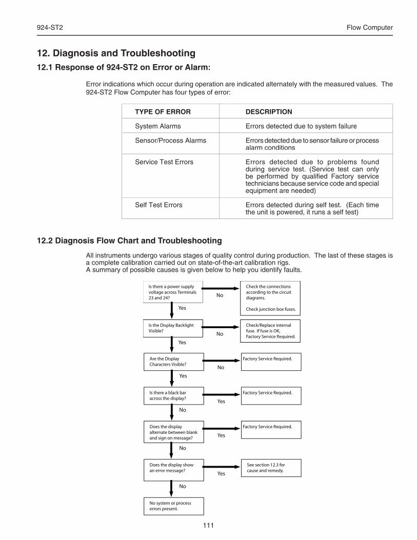
111
924-ST2 Flow Computer
12.2 Diagnosis Flow Chart and Troubleshooting
All instruments undergo various stages of quality control during production. The last of these stages is a complete calibration carried out on state-of-the-art calibration rigs.A summary of possible causes is given below to help you identify faults.
12. Diagnosis and Troubleshooting12.1 Response of 924-ST2 on Error or Alarm:
Error indications which occur during operation are indicated alternately with the measured values. The 924-ST2 Flow Computer has four types of error:
TYPE OF ERROR DESCRIPTIONTYPE OF ERROR DESCRIPTION
System Alarms Errors detected due to system failureSystem Alarms Errors detected due to system failure
Sensor/Process Alarms Errors detected due to sensor failure or process Sensor/Process Alarms Errors detected due to sensor failure or process alarm conditions
Service Test Errors Errors detected due to problems found Service Test Errors Errors detected due to problems found during service test. (Service test can only be performed by qualifi ed Factory service technicians because service code and special equipment are needed)
Self Test Errors Errors detected during self test. (Each time Self Test Errors Errors detected during self test. (Each time the unit is powered, it runs a self test)
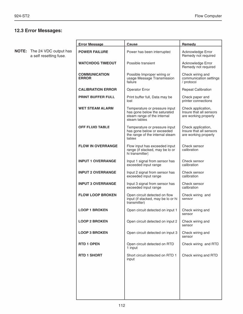
112
924-ST2 Flow Computer
12.3 Error Messages:
Cause
Power has been interrupted
Possible transient
Possible Improper wiring or usage Message Transmission failure
Operator Error
Print buffer full, Data may be lost
Temperature or pressure input has gone below the saturated steam range of the internal steam tables
Temperature or pressure input has gone below or exceeded the range of the internal steam tables
Flow input has exceeded input range (if stacked, may be lo or hi transmitter)
Input 1 signal from sensor has exceeded input range
Input 2 signal from sensor has exceeded input range
Input 3 signal from sensor has exceeded input range
Open circuit detected on fl ow input (if stacked, may be lo or hi transmitter)
Open circuit detected on input 1
Open circuit detected on input 2
Open circuit detected on input 3
Open circuit detected on RTD 1 input
Short circuit detected on RTD 1 input
Remedy
Acknowledge ErrorRemedy not required
Acknowledge ErrorRemedy not required
Check wiring and communication settings / protocol
Repeat Calibration
Check paper and printer connections
Check application, Insure that all sensors are working properly
Check application, Insure that all sensors are working properly
Check sensor calibration
Check sensor calibration
Check sensor calibration
Check sensor calibration
Check wiring and sensor
Check wiring and sensor
Check wiring and sensor
Check wiring and sensor
Check wiring and RTD
Check wiring and RTD
Error Message
POWER FAILURE
WATCHDOG TIMEOUT
COMMUNICATION ERROR
CALIBRATION ERROR
PRINT BUFFER FULL
WET STEAM ALARM
OFF FLUID TABLE
FLOW IN OVERRANGE
INPUT 1 OVERRANGE
INPUT 2 OVERRANGE
INPUT 3 OVERRANGE
FLOW LOOP BROKEN
LOOP 1 BROKEN
LOOP 2 BROKEN
LOOP 3 BROKEN
RTD 1 OPEN
RTD 1 SHORT
RemedyError Message
NOTE: The 24 VDC output has a self resetting fuse.
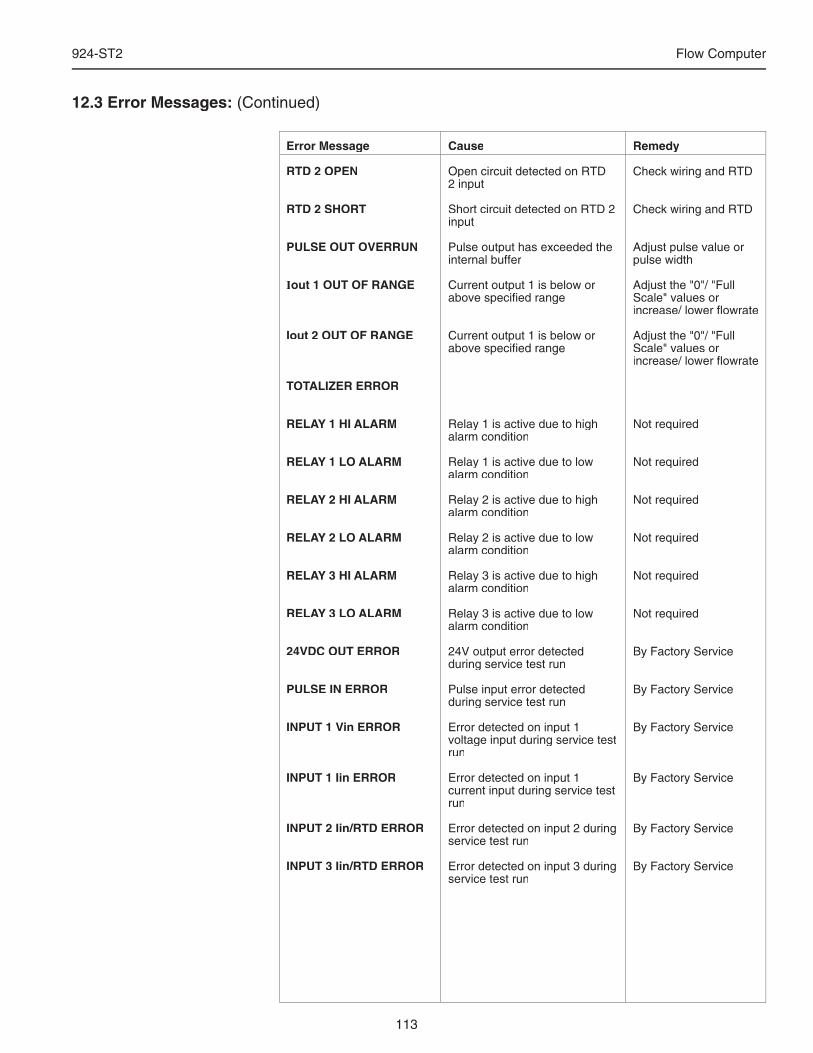
113
924-ST2 Flow Computer
Cause
Open circuit detected on RTD 2 input
Short circuit detected on RTD 2 input
Pulse output has exceeded the internal buffer
Current output 1 is below or above specifi ed range
Current output 1 is below or above specifi ed range
Relay 1 is active due to high alarm condition
Relay 1 is active due to low alarm condition
Relay 2 is active due to high alarm condition
Relay 2 is active due to low alarm condition
Relay 3 is active due to high alarm condition
Relay 3 is active due to low alarm condition
24V output error detected during service test run
Pulse input error detected during service test run
Error detected on input 1 voltage input during service test run
Error detected on input 1 current input during service test run
Error detected on input 2 during service test run
Error detected on input 3 during service test run
Remedy
Check wiring and RTD
Check wiring and RTD
Adjust pulse value or pulse width
Adjust the "0"/ "Full Scale" values or increase/ lower fl owrate
Adjust the "0"/ "Full Scale" values or increase/ lower fl owrate
Not required
Not required
Not required
Not required
Not required
Not required
By Factory Service
By Factory Service
By Factory Service
By Factory Service
By Factory Service
By Factory Service
Error Message
RTD 2 OPEN
RTD 2 SHORT
PULSE OUT OVERRUN
Iout 1 OUT OF RANGE
Iout 2 OUT OF RANGE
TOTALIZER ERROR
RELAY 1 HI ALARM
RELAY 1 LO ALARM
RELAY 2 HI ALARM
RELAY 2 LO ALARM
RELAY 3 HI ALARM
RELAY 3 LO ALARM
24VDC OUT ERROR
PULSE IN ERROR
INPUT 1 Vin ERROR
INPUT 1 Iin ERROR
INPUT 2 Iin/RTD ERROR
INPUT 3 Iin/RTD ERROR
12.3 Error Messages: (Continued)
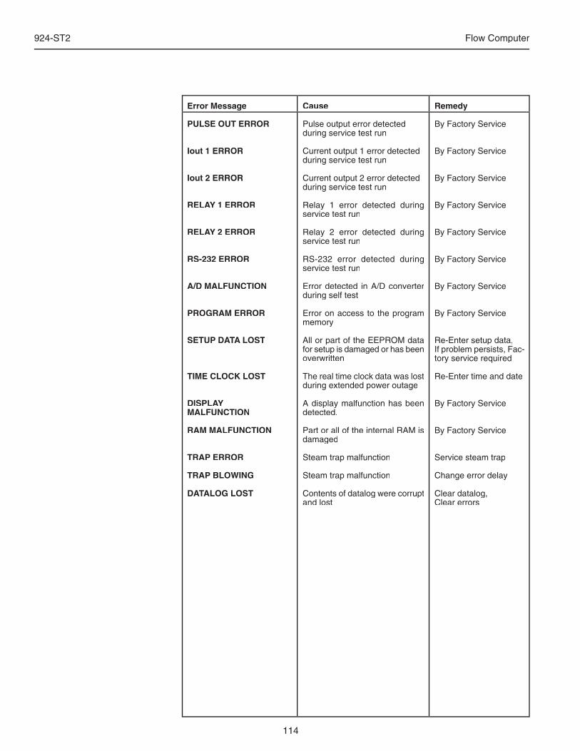
114
924-ST2 Flow Computer
Cause
Pulse output error detected during service test run
Current output 1 error detected during service test run
Current output 2 error detected during service test run
Relay 1 error detected during service test run
Relay 2 error detected during service test run
RS-232 error detected during service test run
Error detected in A/D converter during self test
Error on access to the program memory
All or part of the EEPROM data for setup is damaged or has been overwritten
The real time clock data was lost during extended power outage
A display malfunction has been detected.
Part or all of the internal RAM is damaged
Steam trap malfunction
Steam trap malfunction
Contents of datalog were corrupt and lost
Remedy
By Factory Service
By Factory Service
By Factory Service
By Factory Service
By Factory Service
By Factory Service
By Factory Service
By Factory Service
Re-Enter setup data,If problem persists, Fac-tory service required
Re-Enter time and date
By Factory Service
By Factory Service
Service steam trap
Change error delay
Clear datalog, Clear errors
Error Message
PULSE OUT ERROR
Iout 1 ERROR
Iout 2 ERROR
RELAY 1 ERROR
RELAY 2 ERROR
RS-232 ERROR
A/D MALFUNCTION
PROGRAM ERROR
SETUP DATA LOST
TIME CLOCK LOST
DISPLAY MALFUNCTION
RAM MALFUNCTION
TRAP ERROR
TRAP BLOWING
DATALOG LOST
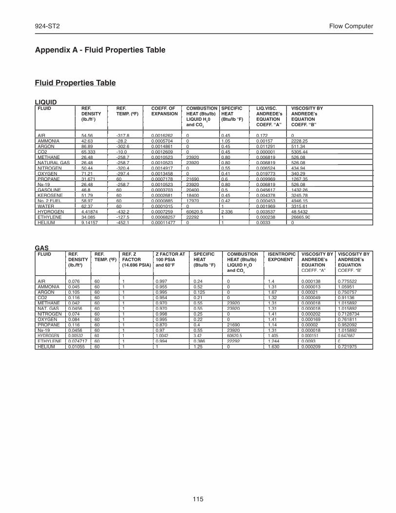
115
924-ST2 Flow Computer
Appendix A - Fluid Properties Table
Fluid Properties TableFluid Properties Table
LIQUID FLUID REF. REF. COEFF. OF COMBUSTION SPECIFIC LIQ.VISC. VISCOSITY BY DENSITY TEMP. (ºF) EXPANSION HEAT (Btu/lb) HEAT ANDREDE’s ANDREDE’s (lb./ft3) LIQUID H20 (Btu/lb °F) EQUATION EQUATION and CO2 COEFF. “A” COEFF. “B”
AIR 54.56 -317.8 0.0016262 0 0.45 0.172 0 AMMONIA 42.63 -28.2 0.0005704 0 1.05 0.00157 2228.25 ARGON 86.89 -302.6 0.0014861 0 0.45 0.011291 511.34 CO2 65.333 -10.0 0.0012609 0 0.45 0.000001 5305.44 METHANE 26.48 -258.7 0.0010523 23920 0.80 0.006819 526.08 NATURAL GAS 26.48 -258.7 0.0010523 23920 0.80 0.006819 526.08 NITROGEN 50.44 -320.4 0.0014917 0 0.55 0.006524 434.94 OXYGEN 71.21 -297.4 0.0013458 0 0.41 0.019773 340.29 PROPANE 31.671 60 0.0007178 21690 0.6 0.009969 1267.35 Nx-19 26.48 -258.7 0.0010523 23920 0.80 0.006819 526.08 GASOLINE 46.8 60 0.0003703 20400 0.5 0.045617 1432.26 KEROSENE 51.79 60 0.0002681 18400 0.45 0.004378 3245.78 No. 2 FUEL 58.97 60 0.0000885 17970 0.42 0.000453 4946.15 WATER 62.37 60 0.0001015 0 1 0.001969 3315.61 HYDROGEN 4.41874 -432.2 0.0007259 60620.5 2.336 0.003537 48.5432 ETHYLENE 34.085 -127.5 0.00068257 22292 1 0.000238 26665.90HELIUM 9.14157 -452.1 0.00011477 0 1 0.0033 0
GAS FLUID REF. REF. REF. Z Z FACTOR AT SPECIFIC COMBUSTION ISENTROPIC VISCOSITY BY VISCOSITY BY DENSITY TEMP. (ºF) FACTOR 100 PSIA HEAT HEAT (Btu/lb) EXPONENT ANDREDE’s ANDREDE’s DENSITY TEMP. (ºF) FACTOR 100 PSIA HEAT HEAT (Btu/lb) EXPONENT ANDREDE’s ANDREDE’s DENSITY TEMP. (ºF) FACTOR 100 PSIA (lb./ft3) (14.696 PSIA) and 60°F (Btu/lb °F) LIQUID H2O EQUATION EQUATION and CO2 COEFF. “A” COEFF. “B”
AIR 0.076 60 1 0.997 0.24 0 1.4 0.000138 0.775522 AMMONIA 0.045 60 1 0.955 0.52 0 1.31 0.000013 1.05951 ARGON 0.105 60 1 0.995 0.125 0 1.67 0.00021 0.750757 CO2 0.116 60 1 0.954 0.21 0 1.32 0.000049 0.91136 METHANE 0.042 60 1 0.970 0.55 23920 1.31 0.000018 1.015892 NAT. GAS 0.0456 60 1 0.970 0.55 23920 1.31 0.000018 1.015892 NITROGEN 0.074 60 1 0.998 0.25 0 1.41 0.000202 0.7128734 OXYGEN 0.084 60 1 0.995 0.22 0 1.41 0.000169 0.761811 PROPANE 0.116 60 1 0.870 0.4 21690 1.14 0.00002 0.952092 Nx-19 0.0456 60 1 0.97 0.55 23920 1.31 0.000018 1.015892 HYDROGEN 0.00532 60 1 1.0042 3.42 60620.5 1.405 0.000151 0.647667 ETHYLENE 0.074717 60 1 0.994 0.386 22292 1.244 0.0093 0HELIUM 0.01055 60 1 1 1.25 0 1.630 0.000209 0.721975
CO2 65.333 -10.0 0.0012609 0 0.45 0.000001 5305.44 METHANE 26.48 -258.7 0.0010523 23920 0.80 0.006819 526.08 NATURAL GAS 26.48 -258.7 0.0010523 23920 0.80 0.006819 526.08
PROPANE 31.671 60 0.0007178 21690 0.6 0.009969 1267.35 PROPANE 31.671 60 0.0007178 21690 0.6 0.009969 1267.35 PROPANE 31.671 60 0.0007178 21690 0.6 0.009969 1267.35 PROPANE 31.671 60 0.0007178 21690 0.6 0.009969 1267.35 PROPANE 31.671 60 0.0007178 21690 0.6 0.009969 1267.35 PROPANE 31.671 60 0.0007178 21690 0.6 0.009969 1267.35 PROPANE 31.671 60 0.0007178 21690 0.6 0.009969 1267.35 PROPANE 31.671 60 0.0007178 21690 0.6 0.009969 1267.35 Nx-19 26.48 -258.7 0.0010523 23920 0.80 0.006819 526.08 Nx-19 26.48 -258.7 0.0010523 23920 0.80 0.006819 526.08 Nx-19 26.48 -258.7 0.0010523 23920 0.80 0.006819 526.08 Nx-19 26.48 -258.7 0.0010523 23920 0.80 0.006819 526.08 Nx-19 26.48 -258.7 0.0010523 23920 0.80 0.006819 526.08 Nx-19 26.48 -258.7 0.0010523 23920 0.80 0.006819 526.08 Nx-19 26.48 -258.7 0.0010523 23920 0.80 0.006819 526.08 Nx-19 26.48 -258.7 0.0010523 23920 0.80 0.006819 526.08 GASOLINE 46.8 60 0.0003703 20400 0.5 0.045617 1432.26 GASOLINE 46.8 60 0.0003703 20400 0.5 0.045617 1432.26 GASOLINE 46.8 60 0.0003703 20400 0.5 0.045617 1432.26 GASOLINE 46.8 60 0.0003703 20400 0.5 0.045617 1432.26 GASOLINE 46.8 60 0.0003703 20400 0.5 0.045617 1432.26 GASOLINE 46.8 60 0.0003703 20400 0.5 0.045617 1432.26 GASOLINE 46.8 60 0.0003703 20400 0.5 0.045617 1432.26 GASOLINE 46.8 60 0.0003703 20400 0.5 0.045617 1432.26
FLUID REF. REF. COEFF. OF COMBUSTION SPECIFIC LIQ.VISC. VISCOSITY BY DENSITY TEMP. (ºF) EXPANSION HEAT (lb./ft and CO
AIR 54.56 -317.8 0.0016262 0 0.45 0.172 0 AMMONIA 42.63 -28.2 0.0005704 0 1.05 0.00157 2228.25 ARGON 86.89 -302.6 0.0014861 0 0.45 0.011291 511.34 CO2 65.333 -10.0 0.0012609 0 0.45 0.000001 5305.44 METHANE 26.48 -258.7 0.0010523 23920 0.80 0.006819 526.08 NATURAL GAS 26.48 -258.7 0.0010523 23920 0.80 0.006819 526.08 NITROGEN 50.44 -320.4 0.0014917 0 0.55 0.006524 434.94 OXYGEN 71.21 -297.4 0.0013458 0 0.41 0.019773 340.29
CO2 65.333 -10.0 0.0012609 0 0.45 0.000001 5305.44 METHANE 26.48 -258.7 0.0010523 23920 0.80 0.006819 526.08 NATURAL GAS 26.48 -258.7 0.0010523 23920 0.80 0.006819 526.08
PROPANE 31.671 60 0.0007178 21690 0.6 0.009969 1267.35 Nx-19 26.48 -258.7 0.0010523 23920 0.80 0.006819 526.08 GASOLINE 46.8 60 0.0003703 20400 0.5 0.045617 1432.26 KEROSENE 51.79 60 0.0002681 18400 0.45 0.004378 3245.78
PROPANE 31.671 60 0.0007178 21690 0.6 0.009969 1267.35 Nx-19 26.48 -258.7 0.0010523 23920 0.80 0.006819 526.08 GASOLINE 46.8 60 0.0003703 20400 0.5 0.045617 1432.26
No. 2 FUEL 58.97 60 0.0000885 17970 0.42 0.000453 4946.15 WATER 62.37 60 0.0001015 0 1 0.001969 3315.61 HYDROGEN 4.41874 -432.2 0.0007259 60620.5 2.336 0.003537 48.5432 ETHYLENE 34.085 -127.5 0.00068257 22292 1 0.000238 26665.90HELIUM 9.14157 -452.1 0.00011477 0 1 0.0033 0
FLUID REF. REF. COEFF. OF COMBUSTION SPECIFIC LIQ.VISC. VISCOSITY BY DENSITY TEMP. (ºF) EXPANSION HEAT
) LIQUID H and CO
AIR 54.56 -317.8 0.0016262 0 0.45 0.172 0 AMMONIA 42.63 -28.2 0.0005704 0 1.05 0.00157 2228.25 ARGON 86.89 -302.6 0.0014861 0 0.45 0.011291 511.34 CO2 65.333 -10.0 0.0012609 0 0.45 0.000001 5305.44 METHANE 26.48 -258.7 0.0010523 23920 0.80 0.006819 526.08 NATURAL GAS 26.48 -258.7 0.0010523 23920 0.80 0.006819 526.08 NITROGEN 50.44 -320.4 0.0014917 0 0.55 0.006524 434.94 OXYGEN 71.21 -297.4 0.0013458 0 0.41 0.019773 340.29
CO2 65.333 -10.0 0.0012609 0 0.45 0.000001 5305.44 METHANE 26.48 -258.7 0.0010523 23920 0.80 0.006819 526.08 NATURAL GAS 26.48 -258.7 0.0010523 23920 0.80 0.006819 526.08
PROPANE 31.671 60 0.0007178 21690 0.6 0.009969 1267.35 Nx-19 26.48 -258.7 0.0010523 23920 0.80 0.006819 526.08 GASOLINE 46.8 60 0.0003703 20400 0.5 0.045617 1432.26 KEROSENE 51.79 60 0.0002681 18400 0.45 0.004378 3245.78 No. 2 FUEL 58.97 60 0.0000885 17970 0.42 0.000453 4946.15 WATER 62.37 60 0.0001015 0 1 0.001969 3315.61 HYDROGEN 4.41874 -432.2 0.0007259 60620.5 2.336 0.003537 48.5432 ETHYLENE 34.085 -127.5 0.00068257 22292 1 0.000238 26665.90HELIUM 9.14157 -452.1 0.00011477 0 1 0.0033 0
PROPANE 31.671 60 0.0007178 21690 0.6 0.009969 1267.35 Nx-19 26.48 -258.7 0.0010523 23920 0.80 0.006819 526.08 GASOLINE 46.8 60 0.0003703 20400 0.5 0.045617 1432.26
FLUID REF. REF. COEFF. OF COMBUSTION SPECIFIC LIQ.VISC. VISCOSITY BY(Btu/lb) HEAT ANDREDE’s ANDREDE’s
0 (Btu/lb °F) EQUATION EQUATION COEFF. “A” COEFF. “B”
AIR 54.56 -317.8 0.0016262 0 0.45 0.172 0 AMMONIA 42.63 -28.2 0.0005704 0 1.05 0.00157 2228.25 ARGON 86.89 -302.6 0.0014861 0 0.45 0.011291 511.34 CO2 65.333 -10.0 0.0012609 0 0.45 0.000001 5305.44 METHANE 26.48 -258.7 0.0010523 23920 0.80 0.006819 526.08 NATURAL GAS 26.48 -258.7 0.0010523 23920 0.80 0.006819 526.08 NITROGEN 50.44 -320.4 0.0014917 0 0.55 0.006524 434.94 OXYGEN 71.21 -297.4 0.0013458 0 0.41 0.019773 340.29
CO2 65.333 -10.0 0.0012609 0 0.45 0.000001 5305.44 METHANE 26.48 -258.7 0.0010523 23920 0.80 0.006819 526.08 NATURAL GAS 26.48 -258.7 0.0010523 23920 0.80 0.006819 526.08
PROPANE 31.671 60 0.0007178 21690 0.6 0.009969 1267.35 Nx-19 26.48 -258.7 0.0010523 23920 0.80 0.006819 526.08 GASOLINE 46.8 60 0.0003703 20400 0.5 0.045617 1432.26 KEROSENE 51.79 60 0.0002681 18400 0.45 0.004378 3245.78 No. 2 FUEL 58.97 60 0.0000885 17970 0.42 0.000453 4946.15 WATER 62.37 60 0.0001015 0 1 0.001969 3315.61 HYDROGEN 4.41874 -432.2 0.0007259 60620.5 2.336 0.003537 48.5432 ETHYLENE 34.085 -127.5 0.00068257 22292 1 0.000238 26665.90HELIUM 9.14157 -452.1 0.00011477 0 1 0.0033 0
PROPANE 31.671 60 0.0007178 21690 0.6 0.009969 1267.35 Nx-19 26.48 -258.7 0.0010523 23920 0.80 0.006819 526.08 GASOLINE 46.8 60 0.0003703 20400 0.5 0.045617 1432.26
FLUID REF. REF. DENSITY TEMP. (ºF) FACTOR 100 PSIA (lb./ft and CO
AIR 0.076 60 1 0.997 0.24 0 1.4 0.000138 0.775522 AMMONIA 0.045 60 1 0.955 0.52 0 1.31 0.000013 1.05951 ARGON 0.105 60 1 0.995 0.125 0 1.67 0.00021 0.750757 CO2 0.116 60 1 0.954 0.21 0 1.32 0.000049 0.91136 METHANE 0.042 60 1 0.970 0.55 23920 1.31 0.000018 1.015892 NAT. GAS 0.0456 60 1 0.970 0.55 23920 1.31 0.000018 1.015892 NITROGEN 0.074 60 1 0.998 0.25 0 1.41 0.000202 0.7128734 OXYGEN 0.084 60 1 0.995 0.22 0 1.41 0.000169 0.761811 PROPANE 0.116 60 1 0.870 0.4 21690 1.14 0.00002 0.952092 Nx-19 0.0456 60 1 0.97 0.55 23920 1.31 0.000018 1.015892 HYDROGEN 0.00532 60 1 1.0042 3.42 60620.5 1.405 0.000151 0.647667 ETHYLENE 0.074717 60 1 0.994 0.386 22292 1.244 0.0093 0HELIUM 0.01055 60 1 1 1.25 0 1.630 0.000209 0.721975
FLUID REF. REF. DENSITY TEMP. (ºF) FACTOR 100 PSIA
) (14.696 PSIA) and 60°F (Btu/lb °F) LIQUID H and CO
AIR 0.076 60 1 0.997 0.24 0 1.4 0.000138 0.775522 AMMONIA 0.045 60 1 0.955 0.52 0 1.31 0.000013 1.05951 ARGON 0.105 60 1 0.995 0.125 0 1.67 0.00021 0.750757 CO2 0.116 60 1 0.954 0.21 0 1.32 0.000049 0.91136 METHANE 0.042 60 1 0.970 0.55 23920 1.31 0.000018 1.015892 NAT. GAS 0.0456 60 1 0.970 0.55 23920 1.31 0.000018 1.015892 NITROGEN 0.074 60 1 0.998 0.25 0 1.41 0.000202 0.7128734 OXYGEN 0.084 60 1 0.995 0.22 0 1.41 0.000169 0.761811 PROPANE 0.116 60 1 0.870 0.4 21690 1.14 0.00002 0.952092 Nx-19 0.0456 60 1 0.97 0.55 23920 1.31 0.000018 1.015892 HYDROGEN 0.00532 60 1 1.0042 3.42 60620.5 1.405 0.000151 0.647667 ETHYLENE 0.074717 60 1 0.994 0.386 22292 1.244 0.0093 0HELIUM 0.01055 60 1 1 1.25 0 1.630 0.000209 0.721975
DENSITY TEMP. (ºF) FACTOR 100 PSIA) (14.696 PSIA) and 60°F (Btu/lb °F) LIQUID H
and CO
AIR 0.076 60 1 0.997 0.24 0 1.4 0.000138 0.775522 AMMONIA 0.045 60 1 0.955 0.52 0 1.31 0.000013 1.05951 ARGON 0.105 60 1 0.995 0.125 0 1.67 0.00021 0.750757 CO2 0.116 60 1 0.954 0.21 0 1.32 0.000049 0.91136 METHANE 0.042 60 1 0.970 0.55 23920 1.31 0.000018 1.015892 NAT. GAS 0.0456 60 1 0.970 0.55 23920 1.31 0.000018 1.015892 NITROGEN 0.074 60 1 0.998 0.25 0 1.41 0.000202 0.7128734 OXYGEN 0.084 60 1 0.995 0.22 0 1.41 0.000169 0.761811 PROPANE 0.116 60 1 0.870 0.4 21690 1.14 0.00002 0.952092 Nx-19 0.0456 60 1 0.97 0.55 23920 1.31 0.000018 1.015892 HYDROGEN 0.00532 60 1 1.0042 3.42 60620.5 1.405 0.000151 0.647667 ETHYLENE 0.074717 60 1 0.994 0.386 22292 1.244 0.0093 0HELIUM 0.01055 60 1 1 1.25 0 1.630 0.000209 0.721975
Z FACTOR AT SPECIFIC DENSITY TEMP. (ºF) FACTOR 100 PSIA
) (14.696 PSIA) and 60°F (Btu/lb °F) LIQUID H and CO
AIR 0.076 60 1 0.997 0.24 0 1.4 0.000138 0.775522 AMMONIA 0.045 60 1 0.955 0.52 0 1.31 0.000013 1.05951 ARGON 0.105 60 1 0.995 0.125 0 1.67 0.00021 0.750757 CO2 0.116 60 1 0.954 0.21 0 1.32 0.000049 0.91136 METHANE 0.042 60 1 0.970 0.55 23920 1.31 0.000018 1.015892 NAT. GAS 0.0456 60 1 0.970 0.55 23920 1.31 0.000018 1.015892 NITROGEN 0.074 60 1 0.998 0.25 0 1.41 0.000202 0.7128734 OXYGEN 0.084 60 1 0.995 0.22 0 1.41 0.000169 0.761811 PROPANE 0.116 60 1 0.870 0.4 21690 1.14 0.00002 0.952092 Nx-19 0.0456 60 1 0.97 0.55 23920 1.31 0.000018 1.015892 HYDROGEN 0.00532 60 1 1.0042 3.42 60620.5 1.405 0.000151 0.647667 ETHYLENE 0.074717 60 1 0.994 0.386 22292 1.244 0.0093 0HELIUM 0.01055 60 1 1 1.25 0 1.630 0.000209 0.721975
Z FACTOR AT SPECIFIC HEAT HEAT (Btu/lb) EXPONENT ANDREDE’s ANDREDE’s
) (14.696 PSIA) and 60°F (Btu/lb °F) LIQUID H and CO
AIR 0.076 60 1 0.997 0.24 0 1.4 0.000138 0.775522 AMMONIA 0.045 60 1 0.955 0.52 0 1.31 0.000013 1.05951 ARGON 0.105 60 1 0.995 0.125 0 1.67 0.00021 0.750757 CO2 0.116 60 1 0.954 0.21 0 1.32 0.000049 0.91136 METHANE 0.042 60 1 0.970 0.55 23920 1.31 0.000018 1.015892 NAT. GAS 0.0456 60 1 0.970 0.55 23920 1.31 0.000018 1.015892 NITROGEN 0.074 60 1 0.998 0.25 0 1.41 0.000202 0.7128734 OXYGEN 0.084 60 1 0.995 0.22 0 1.41 0.000169 0.761811 PROPANE 0.116 60 1 0.870 0.4 21690 1.14 0.00002 0.952092 Nx-19 0.0456 60 1 0.97 0.55 23920 1.31 0.000018 1.015892 HYDROGEN 0.00532 60 1 1.0042 3.42 60620.5 1.405 0.000151 0.647667 ETHYLENE 0.074717 60 1 0.994 0.386 22292 1.244 0.0093 0HELIUM 0.01055 60 1 1 1.25 0 1.630 0.000209 0.721975
HEAT HEAT (Btu/lb) EXPONENT ANDREDE’s ANDREDE’s ) (14.696 PSIA) and 60°F (Btu/lb °F) LIQUID H
and CO
AIR 0.076 60 1 0.997 0.24 0 1.4 0.000138 0.775522 AMMONIA 0.045 60 1 0.955 0.52 0 1.31 0.000013 1.05951 ARGON 0.105 60 1 0.995 0.125 0 1.67 0.00021 0.750757 CO2 0.116 60 1 0.954 0.21 0 1.32 0.000049 0.91136 METHANE 0.042 60 1 0.970 0.55 23920 1.31 0.000018 1.015892 NAT. GAS 0.0456 60 1 0.970 0.55 23920 1.31 0.000018 1.015892 NITROGEN 0.074 60 1 0.998 0.25 0 1.41 0.000202 0.7128734 OXYGEN 0.084 60 1 0.995 0.22 0 1.41 0.000169 0.761811 PROPANE 0.116 60 1 0.870 0.4 21690 1.14 0.00002 0.952092 Nx-19 0.0456 60 1 0.97 0.55 23920 1.31 0.000018 1.015892 HYDROGEN 0.00532 60 1 1.0042 3.42 60620.5 1.405 0.000151 0.647667 ETHYLENE 0.074717 60 1 0.994 0.386 22292 1.244 0.0093 0HELIUM 0.01055 60 1 1 1.25 0 1.630 0.000209 0.721975
ISENTROPIC VISCOSITY BY VISCOSITY BY HEAT HEAT (Btu/lb) EXPONENT ANDREDE’s ANDREDE’s
O EQUATION EQUATION
AIR 0.076 60 1 0.997 0.24 0 1.4 0.000138 0.775522 AMMONIA 0.045 60 1 0.955 0.52 0 1.31 0.000013 1.05951 ARGON 0.105 60 1 0.995 0.125 0 1.67 0.00021 0.750757 CO2 0.116 60 1 0.954 0.21 0 1.32 0.000049 0.91136 METHANE 0.042 60 1 0.970 0.55 23920 1.31 0.000018 1.015892 NAT. GAS 0.0456 60 1 0.970 0.55 23920 1.31 0.000018 1.015892 NITROGEN 0.074 60 1 0.998 0.25 0 1.41 0.000202 0.7128734 OXYGEN 0.084 60 1 0.995 0.22 0 1.41 0.000169 0.761811 PROPANE 0.116 60 1 0.870 0.4 21690 1.14 0.00002 0.952092 Nx-19 0.0456 60 1 0.97 0.55 23920 1.31 0.000018 1.015892 HYDROGEN 0.00532 60 1 1.0042 3.42 60620.5 1.405 0.000151 0.647667 ETHYLENE 0.074717 60 1 0.994 0.386 22292 1.244 0.0093 0HELIUM 0.01055 60 1 1 1.25 0 1.630 0.000209 0.721975
WATER 62.37 60 0.0001015 0 1 0.001969 3315.61 WATER 62.37 60 0.0001015 0 1 0.001969 3315.61 WATER 62.37 60 0.0001015 0 1 0.001969 3315.61 WATER 62.37 60 0.0001015 0 1 0.001969 3315.61 WATER 62.37 60 0.0001015 0 1 0.001969 3315.61 WATER 62.37 60 0.0001015 0 1 0.001969 3315.61 WATER 62.37 60 0.0001015 0 1 0.001969 3315.61 WATER 62.37 60 0.0001015 0 1 0.001969 3315.61
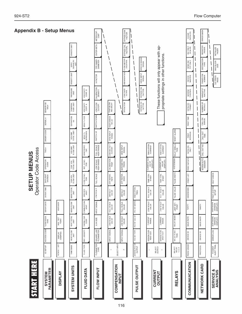
116
924-ST2 Flow Computer
Appendix B - Setup Menus
TIM
E B
AS
EH
EA
T F
LOW
U
NIT
HE
AT
TO
TA
L U
NIT
MA
SS
FLO
W
UN
ITM
AS
S T
OT
AL
UN
ITC
OR
.VO
L.
FLO
W U
NIT
CO
R. V
OL.
T
OT
AL
UN
ITV
OLU
ME
F
LOW
UN
ITV
OLU
ME
T
OT
AL
UN
ITD
EF
INIT
ION
bb
lT
EM
PE
RA
-T
UR
E U
NIT
PR
ES
SU
RE
U
NIT
DE
NS
ITY
UN
ITS
PE
C.
EN
TH
ALP
Y
UN
IT
LEN
GT
H U
NIT
FLU
ID T
YP
ER
EF
. DE
NS
ITY
TH
ER
M. E
XP
. C
OE
F.
CO
MB
US
TIO
N
HE
AT
SP
EC
IFIC
H
EA
TF
LOW
Z-F
AC
-T
OR
RE
F. Z
-FA
C-
TO
RIS
EN
TR
OP
IC
EX
P.
MO
LE %
N
ITR
OG
EN
MO
LE %
CO
2V
ISC
OS
ITY
C
OE
F. A
VIS
CO
SIT
Y
CO
EF
. B
EZ
SE
TU
PA
CC
ES
S C
OD
EF
LOW
EQ
UA
-T
ION
EN
TE
R D
AT
EE
NT
ER
TIM
ET
AG
#O
RD
ER
CO
DE
SE
RIA
L #
SE
NS
OR
SE
-R
IAL#
SC
RO
LL L
IST
DIS
PLA
Y
DA
MP
ING
MA
X. D
EC
. P
OIN
TLA
NG
UA
GE
FLO
WM
ET
ER
T
YP
EIN
PU
T S
IGN
AL
FU
LL S
CA
LELO
W S
CA
LEH
IGH
RA
NG
EF
ULL
SC
ALE
HIG
H R
AN
GE
LOW
FLO
W
CU
TO
FF
CA
LIB
RA
TIO
N
DE
NS
ITY
K-F
AC
TO
RP
IPE
INN
ER
D
IAM
ET
ER
EN
TE
R B
ET
AM
ET
ER
EX
P.
CO
EF
DP
-FA
CT
OR
LOW
PA
SS
F
ILT
ER
LIN
EA
RIZ
AT
ION
FLO
W M
ET
ER
LO
CA
TIO
N
1
SE
LEC
T IN
PU
T
2
LOW
SC
ALE
V
ALU
EF
ULL
SC
ALE
V
ALU
ED
EF
AU
LT
VA
LUE
ST
P R
EF
ER
-E
NC
EC
ALI
BR
AT
ION
T
EM
PLO
W D
ELT
A T
C
UT
OF
FV
IEW
INP
UT
S
IGN
AL
INP
UT
SIG
NA
LLO
W S
CA
LE
VA
LUE
FU
LL S
CA
LEV
ALU
ED
EF
AU
LT
VA
LUE
ST
P R
EF
ER
-E
NC
EB
AR
OM
ET
RIC
PR
ES
SV
IEW
INP
UT
S
IGN
AL
INP
UT
SIG
NA
L
AS
SIG
N P
ULS
E
AS
SIG
N P
ULS
E
OU
TP
UT
PU
LSE
TY
PE
PU
LSE
VA
LUE
PU
LSE
WID
TH
SIM
ULA
TIO
N
FR
EQ
.
1
SE
LEC
T
OU
TP
UT
2
LOW
SC
ALE
V
ALU
ET
IME
CO
N-
ST
AN
T
CU
RR
EN
T O
UT
V
ALU
E(D
ISP
LAY
)
SIM
ULA
TIO
N
CU
RR
EN
TA
SS
IGN
CU
R-
RE
NT
OU
T.
CU
RR
EN
T
RA
NG
E
LOW
SC
ALE
V
ALU
EF
ULL
SC
ALE
V
ALU
ET
IME
CO
N-
ST
AN
T
CU
RR
EN
T O
UT
V
ALU
E(D
ISP
LAY
)
SIM
ULA
TIO
N
CU
RR
EN
TA
SS
IGN
CU
R-
RE
NT
OU
T.
CU
RR
EN
T
RA
NG
E
SE
LEC
T
RE
LAY
1, 2
, 3
LIM
IT S
ET
-P
OIN
TP
ULS
E V
ALU
EH
YS
TE
RE
SIS
RE
LAY
FU
NC
-T
ION
RE
LAY
MO
DE
FU
LL S
CA
LE
VA
LUE
EX
AM
INE
A
UD
IT T
RA
ILE
RR
OR
LO
GS
OF
TW
AR
E
VE
RS
ION
(DIS
PLA
Y)
HA
RD
WA
RE
V
ER
SIO
N(D
ISP
LAY
)
PR
INT
SY
ST
EM
S
ET
UP
SE
LF C
HE
CK
SY
ST
EM
PA
RA
ME
TE
R
SE
RV
ICE
&
AN
ALY
SIS
CO
MM
UN
UIC
AT
ION
RE
LA
YS
CU
RR
EN
TO
UT
PU
T
PU
LS
E O
UT
PU
T
CO
MP
EN
SA
TIO
NIN
PU
T
FL
OW
INP
UT
FL
UID
DA
TA
SY
ST
EM
UN
ITS
DIS
PL
AY
SQ
UA
RE
LA
W
FLO
WM
ET
ER
BY
PA
SS
CA
L.
FA
CT
OR
LB
YP
AS
S E
AM
F
AC
TO
R
LOW
SC
ALE
RE
SE
T A
LAR
MP
ULS
E W
IDT
HR
ELA
Y S
IMU
LA-
TIO
N
SE
TU
P M
EN
US
Ope
rato
r C
ode
Acc
ess
The
se fu
nctio
ns w
ill o
nly
appe
ar w
ith a
p-pr
opria
te s
ettin
gs in
oth
er fu
nctio
ns.
PR
OT
OC
OL
DE
VIC
E ID
BA
UD
RA
TE
PA
RIT
YN
ET
WO
RK
CA
RD
SW
ITC
H U
PS
WIT
CH
DO
WN
VIE
W IN
PU
T
SIG
NA
LV
IEW
HI R
AN
GE
V
IEW
HI R
AN
GE
S
IGN
AL
BY
PA
SS
DC
F
AC
TO
RB
YP
AS
S Y
M
FA
CT
OR
OP
ER
AT
OR
CO
DE
DA
YLI
GH
T
SA
VIN
GS
TR
AP
ER
RO
R
DE
LAY
TR
AP
BLO
W-
ING
DE
LAY
RS
232
US
AG
ED
EV
ICE
IDB
AU
D R
AT
EP
AR
ITY
HA
ND
SH
AK
EP
RIN
T L
IST
PR
INT
INIT
IAT
EP
RIN
T
INT
ER
VA
LP
RIN
T T
IME
DA
TA
LOG
ON
LYD
AT
ALO
GF
OR
MA
TM
OD
EM
C
ON
TR
OL
DE
VIC
E
MA
ST
ER
SE
ND
INC
T
OT
ON
LYIN
C O
NLY
S
CA
LER
CLE
AR
D
AT
ALO
G
CA
LL O
N
ER
RO
RN
UM
BE
R O
F
RE
DIA
LSH
AN
GU
P IF
IN
AC
TIV
EP
AG
ER
PIN
N
UM
BE
RD
ES
TIN
AT
ION
T
YP
ER
EG
IST
ER
P
AG
ER
ER
RO
R M
AS
K
CLP
PR
OG
-R
ES
SM
AX
BLO
CK
S
IZE
INIT
IALI
ZE
P
AG
ER
MO
DE
M A
UT
O
AN
SW
ER
CA
LL O
UT
NO
CA
LL O
UT
T
IME
STAR
T HE
RE
ILV
A S
IZE
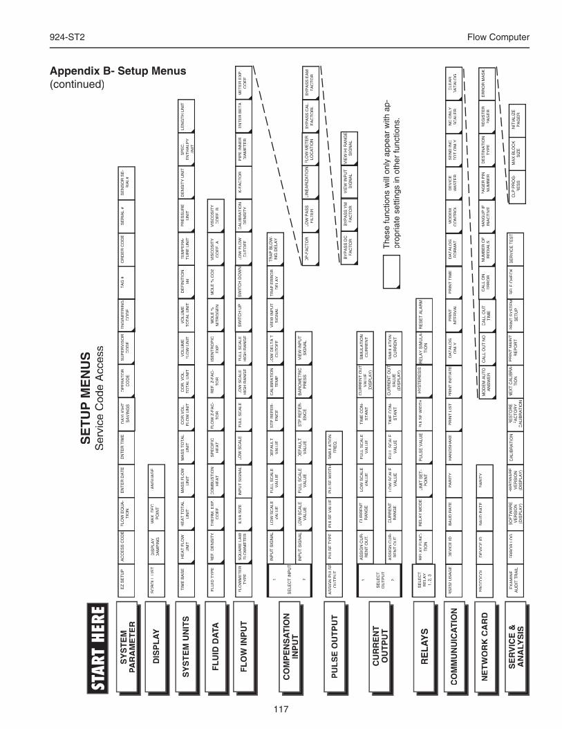
117
924-ST2 Flow Computer
Appendix B- Setup Menus (continued)
FLO
WM
ET
ER
T
YP
EIN
PU
T S
IGN
AL
FU
LL S
CA
LELO
W S
CA
LEH
IGH
RA
NG
EF
ULL
SC
ALE
HIG
H R
AN
GE
LOW
FLO
W
CU
TO
FF
CA
LIB
RA
TIO
N
DE
NS
ITY
K-F
AC
TO
RP
IPE
INN
ER
D
IAM
ET
ER
EN
TE
R B
ET
AM
ET
ER
EX
P.
CO
EF
FL
OW
INP
UT
SQ
UA
RE
LA
W
FLO
WM
ET
ER
LOW
SC
ALE
SW
ITC
H U
PS
WIT
CH
DO
WN
TIM
E B
AS
EH
EA
T F
LOW
U
NIT
HE
AT
TO
TA
L U
NIT
MA
SS
FLO
W
UN
ITM
AS
S T
OT
AL
UN
ITC
OR
.VO
L.
FLO
W U
NIT
CO
R. V
OL.
T
OT
AL
UN
ITV
OLU
ME
F
LOW
UN
ITV
OLU
ME
T
OT
AL
UN
ITD
EF
INIT
ION
bb
lT
EM
PE
RA
-T
UR
E U
NIT
PR
ES
SU
RE
U
NIT
DE
NS
ITY
UN
ITS
PE
C.
EN
TH
ALP
Y
UN
IT
LEN
GT
H U
NIT
FLU
ID T
YP
ER
EF
. DE
NS
ITY
TH
ER
M. E
XP
. C
OE
F.
CO
MB
US
TIO
N
HE
AT
SP
EC
IFIC
H
EA
TF
LOW
Z-F
AC
-T
OR
RE
F. Z
-FA
C-
TO
RIS
EN
TR
OP
IC
EX
P.
MO
LE %
N
ITR
OG
EN
MO
LE %
CO
2V
ISC
OS
ITY
C
OE
F. A
VIS
CO
SIT
Y
CO
EF
. B
EZ
SE
TU
PA
CC
ES
S C
OD
EF
LOW
EQ
UA
-T
ION
EN
TE
R D
AT
EE
NT
ER
TIM
EO
PE
RA
TO
RC
OD
ET
AG
#O
RD
ER
CO
DE
SE
RIA
L #
SE
NS
OR
SE
-R
IAL#
SC
RO
LL L
IST
DIS
PLA
Y
DA
MP
ING
MA
X. D
EC
. P
OIN
TLA
NG
UA
GE
1
SE
LEC
T IN
PU
T
2
LOW
SC
ALE
V
ALU
EF
ULL
SC
ALE
V
ALU
ED
EF
AU
LT
VA
LUE
ST
P R
EF
ER
-E
NC
EC
ALI
BR
AT
ION
T
EM
PLO
W D
ELT
A T
C
UT
OF
FV
IEW
INP
UT
S
IGN
AL
INP
UT
SIG
NA
LLO
W S
CA
LE
VA
LUE
FU
LL S
CA
LEV
ALU
ED
EF
AU
LT
VA
LUE
ST
P R
EF
ER
-E
NC
EB
AR
OM
ET
RIC
PR
ES
SV
IEW
INP
UT
S
IGN
AL
INP
UT
SIG
NA
L
AS
SIG
N P
ULS
E
AS
SIG
N P
ULS
E
OU
TP
UT
PU
LSE
TY
PE
PU
LSE
VA
LUE
PU
LSE
WID
TH
SIM
ULA
TIO
N
FR
EQ
.
1
SE
LEC
T
OU
TP
UT
2
LOW
SC
ALE
V
ALU
ET
IME
CO
N-
ST
AN
T
CU
RR
EN
T O
UT
V
ALU
E(D
ISP
LAY
)
SIM
ULA
TIO
N
CU
RR
EN
TA
SS
IGN
CU
R-
RE
NT
OU
T.
CU
RR
EN
T
RA
NG
E
LOW
SC
ALE
V
ALU
EF
ULL
SC
ALE
V
ALU
ET
IME
CO
N-
ST
AN
T
CU
RR
EN
T O
UT
V
ALU
E(D
ISP
LAY
)
SIM
ULA
TIO
N
CU
RR
EN
TA
SS
IGN
CU
R-
RE
NT
OU
T.
CU
RR
EN
T
RA
NG
E
RS
232
US
AG
ED
EV
ICE
IDB
AU
D R
AT
EP
AR
ITY
HA
ND
SH
AK
EP
RIN
T L
IST
FU
LL S
CA
LE
VA
LUE
EX
AM
INE
A
UD
IT T
RA
ILE
RR
OR
LO
GS
OF
TW
AR
E
VE
RS
ION
(DIS
PLA
Y)
HA
RD
WA
RE
V
ER
SIO
N(D
ISP
LAY
)
PR
INT
SY
ST
EM
S
ET
UP
SE
LF C
HE
CK
SY
ST
EM
PA
RA
ME
TE
R
SE
RV
ICE
&
AN
ALY
SIS
CO
MM
UN
UIC
AT
ION
CU
RR
EN
TO
UT
PU
T
PU
LS
E O
UT
PU
T
CO
MP
EN
SA
TIO
NIN
PU
T
FL
UID
DA
TA
SY
ST
EM
UN
ITS
DIS
PL
AY
SU
PE
RV
ISO
RC
OD
E
CA
LIB
RA
TIO
NR
ES
TO
RE
F
AC
TO
RY
C
ALI
BR
AT
ION
NE
XT
CA
LIB
RA
-N
EX
T C
ALI
BR
A-
TIO
NP
RIN
T M
AIN
T.
RE
PO
RT
SE
RV
ICE
TE
ST
SE
TU
P M
EN
US
Ser
vice
Cod
e A
cces
s
The
se fu
nctio
ns w
ill o
nly
appe
ar w
ith a
p-pr
opria
te s
ettin
gs in
oth
er fu
nctio
ns.
SE
LEC
T
RE
LAY
1, 2
, 3
LIM
IT S
ET
-P
OIN
TP
ULS
E V
ALU
EH
YS
TE
RE
SIS
RE
LAY
FU
NC
-T
ION
RE
LAY
MO
DE
RE
LA
YS
RE
SE
T A
LAR
MP
ULS
E W
IDT
HR
ELA
Y S
IMU
LA-
TIO
N
PR
OT
OC
OL
DE
VIC
E ID
BA
UD
RA
TE
PA
RIT
YN
ET
WO
RK
CA
RD
DP
-FA
CT
OR
LOW
PA
SS
F
ILT
ER
LIN
EA
RIZ
AT
ION
FLO
W M
ET
ER
LO
CA
TIO
NB
YP
AS
S C
AL.
F
AC
TO
RL
BY
PA
SS
EA
M
FA
CT
OR
VIE
W IN
PU
T
SIG
NA
LV
IEW
HI R
AN
GE
V
IEW
HI R
AN
GE
S
IGN
AL
BY
PA
SS
DC
F
AC
TO
RB
YP
AS
S Y
M
FA
CT
OR
PR
INT
INIT
IAT
EP
RIN
T
INT
ER
VA
LP
RIN
T T
IME
DA
TA
LOG
ON
LYD
AT
ALO
GF
OR
MA
TM
OD
EM
C
ON
TR
OL
DE
VIC
E
MA
ST
ER
DA
YLI
GH
T
SA
VIN
GS
EN
GIN
EE
RIN
GC
OD
E
TR
AP
ER
RO
R
DE
LAY
TR
AP
BLO
W-
ING
DE
LAY
SE
ND
INC
T
OT
ON
LYIN
C O
NLY
S
CA
LER
CLE
AR
D
AT
ALO
G
CA
LL O
N
ER
RO
RN
UM
BE
R O
F
RE
DIA
LSH
AN
GU
P IF
IN
AC
TIV
EP
AG
ER
PIN
N
UM
BE
RD
ES
TIN
AT
ION
T
YP
ER
EG
IST
ER
P
AG
ER
ER
RO
R M
AS
K
CLP
PR
OG
-R
ES
SM
AX
BLO
CK
S
IZE
INIT
IALI
ZE
P
AG
ER
MO
DE
M A
UT
O
AN
SW
ER
CA
LL O
UT
NO
CA
LL O
UT
T
IME
STAR
T HE
RE
ILV
A S
IZE
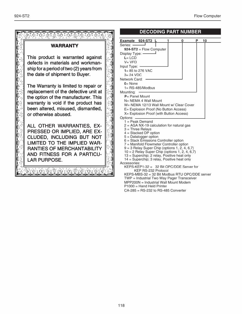
118
924-ST2 Flow Computer
DECODING PART NUMBER
Example 924-ST2 L 1 0 P 10Series:
924-ST2 = Flow ComputerDisplay Type:
L= LCD V= VFDInput Type:
1= 85 to 276 VAC 3= 24 VDCNetwork Card:
0= None 1= RS-485/ModbusMounting:
P= Panel Mount N= NEMA 4 Wall Mount W= NEMA 12/13 Wall Mount w/ Clear Cover E= Explosion Proof (No Button Access) X= Explosion Proof (with Button Access)Options: 1 = Peak Demand 2 = AGA NX-19 calculation for natural gas 3 = Three Relays 4 = Stacked DP option 5 = Datalogger option 6 = Stack Emissions Controller option 7 = Manifold Flowmeter Controller option 9 = 3 Relay Super Chip (options 1, 2, 4, 6,7) 10 = 2 Relay Super Chip (options 1, 2, 4, 6,7) 13 = Superchip; 2 relay, Positive heat only 14 = Superchip; 3 relay, Positive heat onlyAccessories: KEPS-KEP1-32 = 32 Bit OPC/DDE Server for KEP RS-232 Protocol KEPS-MBS-32 = 32 Bit Modbus RTU OPC/DDE server TWP = Industrial Two Way Pager Transceiver MPP200N = Industrial Wall Mount Modem P1000 = Hand Held Printer CA-285 = RS-232 to RS-485 Converter
WARRANTY
This product is warranted against defects in materials and workman-ship for a period of two (2) years from the date of shipment to Buyer.
The Warranty is limited to repair or replacement of the defective unit at the option of the manufacturer. This warranty is void if the product has been altered, misused, dismantled, or otherwise abused.
ALL OTHER WARRANTIES, EX-PRESSED OR IMPLIED, ARE EX-CLUDED, INCLUDING BUT NOT LIMITED TO THE IMPLIED WAR-RANTIES OF MERCHANTABILITY AND FITNESS FOR A PARTICU-LAR PURPOSE.