9!19219 - ntrs.nasa.gov
26
9!"19219 Mini-Dome Fresnel Lens Photovoltaic Concentrator Development Mark J. O'Neill ENTECH, I7_c. DFW Airport, TX Michael F. Piszczor, Jr. NASA Lewis Research Center Cleveland, OH Introduction Since 1986, our organizations have been actively developing a new high-perfor- mance, light-weight space photovoltaic concentrator array [refs. 1-6]. This develop- ment work is being done under Small Business Innovation Research (SBIR) contracts funded by NASA and SDIO. The new array is the first space photovoltaic concen- trator system to use a refractive optical concentrator in the form of a unique, dome- shaped, point-focus, Fresnel lens [refs. 7-9]. The new array is also the first space photovoltaic concentrator system to utilize prismatic cell covers to eliminate gridline obscuration losses [refs. 10-11]. By combining these new array features with state- of-the-art cell technology, we anticipate substantial improvements over present space power systems in both array power density (watts/square meter) and specific power (watts/kilogram). The three most critical elements of the new array are the lens, the prismatic cell cover, and the photovoltaic cell. During 1987 and 1988, prototypes of the latter two elements were successfully developed and tested [refs. 5-6]. The prismatic cover has provided cell performance enhancement levels in close agreement with predictions. Likewise, the prism-covered cell performance has matched predictions. In fact, gal- lium arsenide cells made by Varian have achieved over 24% efficiency (at 100 AM0 suns irradiance and 25C) after prismatic cover application, the highest single-junction space cell efficiency yet measured by NASA Lewis, as we described at the last SPRAT Conference. Since the last SPRAT Conference, the master tooling required to make the third critical element of the new array, the mini-dome Fresnel lens, was completed. This state-of-the-art diamond-turned tooling was made to ENTECIt specifications by 3M Company. During 1989, prototypes of the mini-dome lens optical concentrator have been successfully made from this tooling and tested. Outdoor test results, fully discussed in later paragraphs, confirm that the mini-dome lens will provide excel- lent optical efficiency levels. In fact, the first prototype flexible silicone rubber lens achieved 86_ net optical efficiency. Also since the last SPRAT Conference, we have also been adapting the prismatic cell cover technology to Boeing's new mechanically stacked multi-junction (MSMJ) 443
Transcript of 9!19219 - ntrs.nasa.gov
9!"19219Mini-Dome Fresnel Lens Photovoltaic Concentrator Development
Mark J. O'Neill
ENTECH, I7_c.DFW Airport, TX
Michael F. Piszczor, Jr.NASA Lewis Research Center
Cleveland, OH
Introduction
Since 1986, our organizations have been actively developing a new high-perfor-
mance, light-weight space photovoltaic concentrator array [refs. 1-6]. This develop-
ment work is being done under Small Business Innovation Research (SBIR) contracts
funded by NASA and SDIO. The new array is the first space photovoltaic concen-
trator system to use a refractive optical concentrator in the form of a unique, dome-
shaped, point-focus, Fresnel lens [refs. 7-9]. The new array is also the first space
photovoltaic concentrator system to utilize prismatic cell covers to eliminate gridline
obscuration losses [refs. 10-11]. By combining these new array features with state-
of-the-art cell technology, we anticipate substantial improvements over present space
power systems in both array power density (watts/square meter) and specific power
(watts/kilogram).
The three most critical elements of the new array are the lens, the prismatic cell
cover, and the photovoltaic cell. During 1987 and 1988, prototypes of the latter two
elements were successfully developed and tested [refs. 5-6]. The prismatic cover has
provided cell performance enhancement levels in close agreement with predictions.
Likewise, the prism-covered cell performance has matched predictions. In fact, gal-
lium arsenide cells made by Varian have achieved over 24% efficiency (at 100 AM0
suns irradiance and 25C) after prismatic cover application, the highest single-junction
space cell efficiency yet measured by NASA Lewis, as we described at the last SPRAT
Conference.
Since the last SPRAT Conference, the master tooling required to make the third
critical element of the new array, the mini-dome Fresnel lens, was completed. This
state-of-the-art diamond-turned tooling was made to ENTECIt specifications by 3M
Company. During 1989, prototypes of the mini-dome lens optical concentrator have
been successfully made from this tooling and tested. Outdoor test results, fully
discussed in later paragraphs, confirm that the mini-dome lens will provide excel-
lent optical efficiency levels. In fact, the first prototype flexible silicone rubber lens
achieved 86_ net optical efficiency.
Also since the last SPRAT Conference, we have also been adapting the prismatic
cell cover technology to Boeing's new mechanically stacked multi-junction (MSMJ)
443

cell, which is fully compatible with the mini-dome lens concentrator approach. Boe-
ing's new cell (fully described in another paper at this SPRAT Conference [ref. 12])
includes a transparent gallium arsenide (GaAs) top cell and a gallium antimonide
(GaSb) bottom cell, with both cells using prismatic covers to eliminate gridline ob-
scuration losses. These stacked cells have recently achieved over 30% AM0 efficiency
(at 25C and 100 suns irradiance) in simulator testing. This new MSMJ cell technology
has excellent long-term implications for the mini-dome lens concentrator array.
The following paragraphs provide an update on the mini-dome lens concentrator
array development program.
System Description
Since the mini-dome Fresnel lens concentrator array has been described in pre-
vious papers [refs. 1-6], only a brief description of the new concentrator system will
be presented here. Figure 1 shows an individual dome lens photovoltaic concentrator
module. The square-aperture dome lens focusses sunlight onto a state-of-the-art con-
centrator cell (i.e., a single-junction gallium arsenide cell or a tandem MSMJ cell). An
optically clear silicone rubber prismatic cell cover is bonded to the upper surface of
each cell to eliminate gridline obscuration losses. A high-thermal-conductivity dielec-
tric layer is used to bond the cell assembly to the aluminum backplane radiator. Top
and bottom electrical contacts are used to join cells into desired series/parallel cir-
cuits. The 200 micron thick radiator and the 150 micron thick aluminum honeycomb
structure are bonded together to form a rigid assembly, which is coated with a white
thermal control coating (with high infrared emittance and low solar absorptance).
Each individual dome lens module provides an operational power output of about
0.4 watt. Multiple modules are integrated into a larger panel, capable of providing
tens or hundreds of watts, as shown in Figure 2. The individual dome lenses are
placed within the square slots forming the honeycomb, with the top of each lens
located below the top of the honeycomb after assembly. Thus, panels can be stacked
on top of one another, without touching the lenses, thereby allowing compact stowage
of multiple panels. I'o form multi-kilowatt arrays, the panels have been designed
for use with existing automatically deploying space structures, such as the Astro
Aerospace extendible support structure (ESS) [ref. 13], as shown in Figure 3. Such
structures have been designed for deploying and supporting other space photovoltaic
concentrator panels, such as the TRW mini-Cassegrainian concentrator (MCC) [ref.
14]. Due to its higher power density, the dome lens concentrator (DLC) will require
a smaller array size than the MCC concentrator, as shown in the lower portion of
Figure 3.
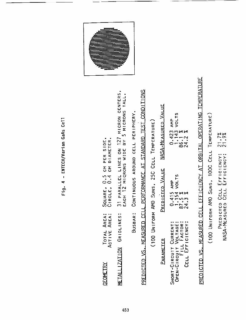
Figure 4 shows the ENTECH/Varian GaAs concentrator cell geometry and per-
formance after prismatic cover application. NASA Lewis measured the cell efficiency
to be over 24% at 25C and 100 AM0 suns, and about 22% at 100C and 100 AM0 suns.
444
Similar performance can be expected for a transparent version of the GaAs cell, form-
ing the top cell in a tandem MSMJ assembly, as Boeing will report at this SPRAT
Conference [ref. 12]. When a prismatically covered GaSb cell is placed beneath such
a transparent GaAs cell, a boost efficiency of about 9% is currently attainable, based
on recent simulator measurements for a GaSb cell under a GaAs filter [ref. 12].
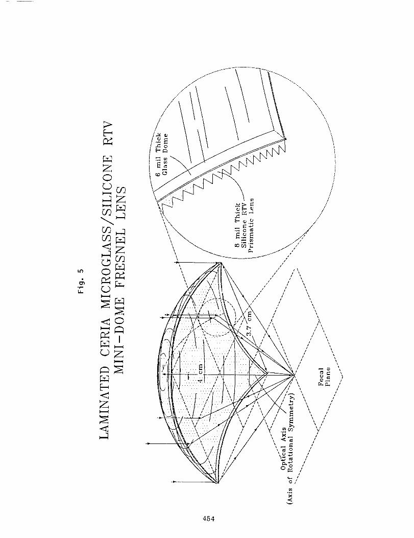
Figure 5 shows the baseline mini-dome Fresnel lens configuration. The shape of
the lens corresponds to a unique geometry which provides minimal reflection loss for
each prism, and thus maximal transnfittance for the lens [ref. 7]. Also, this design
provides a smaller solar image, smaller optical aberrations, and greatly improved
manufacturing tolerances, compared to other concentrator designs [ref. 8]. The lens
has a 4.0 cm focal length and a 3.7 cm square aperture (13.7 sq.cm, in area). The lens
is designed to focus incident sunlight onto a 0.4 cm diameter cell (0.126 sq.cm, active
area), the same size cell as that used in the TRW MCC reflective space concentrator
[ref. 14].
The lens irradiance profile can be tailored by selecting the appropriate angle for
each of the individual prisms comprising the lens, such that the individual prism
images overlap to provide the desired irradiance distribution across the focal plane.
For the present lens, the prism angles have been optimized to form an image over a
small 0.26 cm diameter circular portion of the cell, to allow the module to tolerate a 1
degree tracking error without appreciable loss in performance [ref. 6]. Figure 6 shows
this lens design approach, including the photon flux distribution over the cell with
and without a sun-tracking error. To provide this smaller image size, the predicted
peak irradiance at the center of the cell is about 400 suns, which is quite tolerable
for the cell under consideration [ref. 6]. The predicted optical efficiency of the lens
is above 90%, comparable to ENTECH's terrestrial photovoltaic concentrator lenses.
The optical efficiency could be further improved by applying anti-reflection coatings
to the lens surfaces.
The lens materials have been selected to provide good optical performance, as
well as durability in the orbital environment. The ceria-doped microglass superstrate
is the same material which has been used for cover slides on one-sun photovoltaic
cells in space. The clear silicone RTV substrate is the same material which has
been used as an adhesive to bond cover slides to one-sun photovoltaic cells in space.
Diamond-turned master tooling, which is used to mold the silicone rubber Fresnel
lens, was delivered to ENTECH by 3M Company in late 1988. Prototype silicone
rubber lenses have since been successfully made and tested, as highlighted in a later
paragraph. Glass superstrate thermal forming experiments have been underway for
several months at both ENTECtt and outside vendor facilities. While the glass form-
ing appears to be straightforward, the best methods of manufacturing such microglass
domes have not yet been selected.
The following paragraphs discuss recent test results on the key components of the
mini-dome space photovoltaic concentrator system.
445
Key Component Test Results
In 1988,NASA Lewis tested severalof the latest gallium arsenidecells (madeby Varian of Palo Alto, California) under simulatedspacesunlight, beforeand afterprismatic coverapplication by ENTECH. Test results (at 100 AM0 suns irradianceand 25C) for one of these cells are shown in Figure 4. The cells utilize a parallelgridline geometry,with grids about 12 microns wide on 127micron centers. Afterprismatic covering,the cell efficiencyincreasedabout 11%,due principally to a 12%short-circuit current increase.This performanceenhancementmatchesexpectationsfor the prismatic cover in this application. The 24% cell efficiency of Figure 4 is
the highest single-junction space cell efficiency measured by NASA Lewis to date.
This same prism-covered cell achieved about 22% efficiency at 100 AM0 suns and
100C, the expected operational conditions on orbit for the mini-dome lens array.
Thus, prototype cells and prism covers have demonstrated performance levels in close
agreement with early predictions [refs. 1-2].
In 1989, Boeing has achieved over 30% AM0 efficiency in simulator tests of their
GaAs/GaSb MSMJ cell system, which includes prismatic covers on both the top and
bottom cells. This unprecedented efficiency was achieved at 100 AM0 suns irradiance
and 25C cell temperature, as fully described in another paper at this conference [ref.
12]. This MSMJ cell is ideally suited for use in the mini-dome lens panel, where
it will provide a significant array performance improvement, as discussed in a later
paragraph.
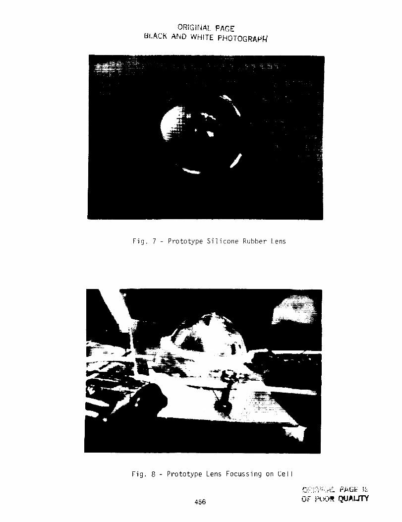
During 1989, we have obtained tile first test data on the mini-dome Fresnel lens.
Prototype silicone rubber lenses, without the microglass superstrates, have been sue-
cessfully molded. A typical lens is shown in Figure 7, with centimeter graph paper
in tile background. Figure 8 shows a prototype lens focussing actual sunlight onto
a test gallium arsenide cell. This cell is a 1985-vintage Cassegrainian concentrator
cell made by Applied Solar Energy Corporation (ASEC) and furnished to ENTECH
by NASA Lewis. The cell has a radial gridline pattern, not compatible with the
prismatic cover, and a short-circuit current response typical of ASEC cells of that
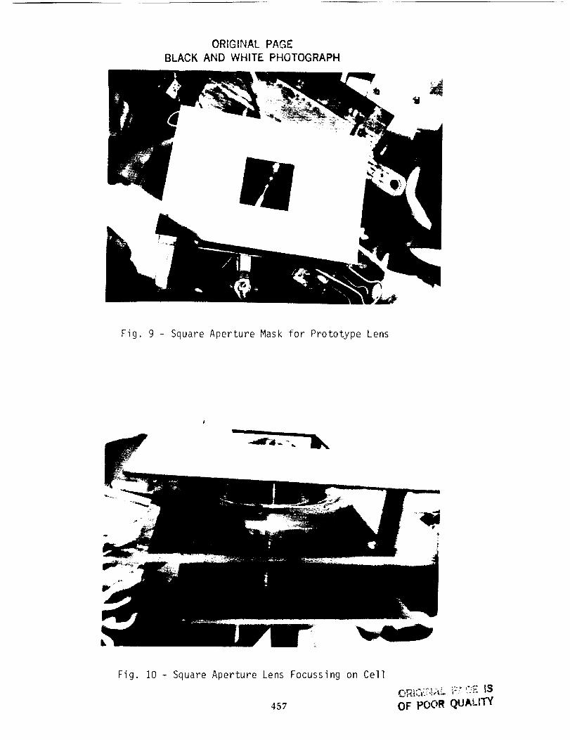
vintage [ref. 15]. The test results reported below were all obtained with the same
heat sink-mounted ASEC cell, by measuring its short-circuit current response under
three different irradiance conditions: (i) one direct normal sun irradiance; (ii) the
full circular aperture dome lens irradiance (Figure 8); and (iii) the masked dome lens
irradiance (Figures 9 and 10), which simulated the square aperture of the mini-dome
lens discussed in previous paragraphs. The full dome lens has an aperture diameter
of about 5.5 cm. Since the lens was made of flexible silicone rubber without the mi-
croglass superstrate needed for rigidity, its thickness was increased to about double
the 200 micron (8 rail) design value of Figure 5, to make the dome self-supporting.
For testing, the dome lens was adhesively bonded to an acrylic sheet, with a hole
in the sheet to allow the focussed sunlight to travel h'om the lens to the cell. The
hole was cut with an available saw with a 5.4 cm diameter, slightly smaller than the
446
full dome lens aperture. Sincethe hole wassmaller than the lens aperture, somerayblockageoccurredduring the full domelenstesting. For the more important testing,with a 3.7 cm squareaperture surroundedby an opaquemaskplaced in front of thedome lens, ray blockageby the undersizedhole wasnegligible.
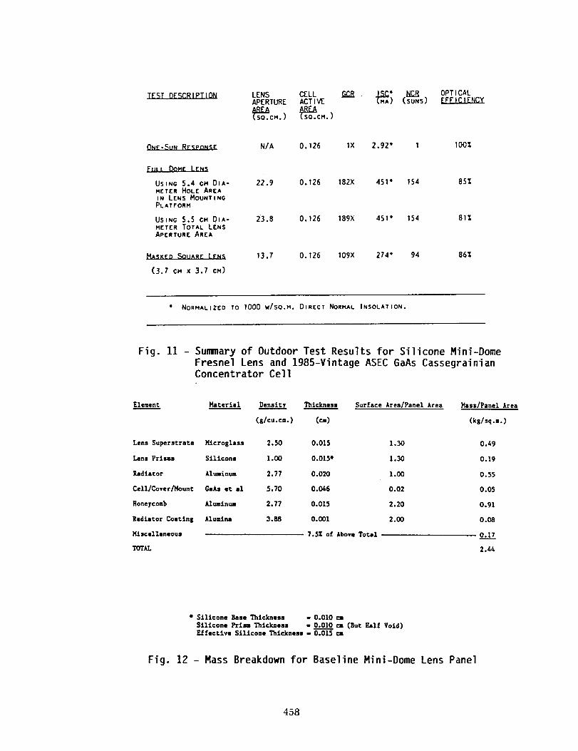
Figure 11 summarizesthe outdoor test results for the prototype silicone mini-
dome Fresnel lens. The data columns of Figure 11 include lens aperture area (two
bracketing values for the full dome lens test); cell active area; geometric concentration
ratio (GCR), which is the ratio of lens aperture area to cell active area; the cell short-
circuit current (ISC); net concentration ratio (NCR), which is the ratio of the ISC
produced with the lens in place to the ISC produced at one-sun with only direct
normal insolation reaching the cell; and optical efficiency, which is the ratio of NCR
to GCR. Note that the full dome lens had a measured optical efficiency between 81c_,
and 85%, depending on whether the gross lens aperture area or the mounting plate
hole area is used as the true aperture for the test. More importantly, note that the
masked square aperture lens had a measured optical efficiency of 86%.
The measured 86% optical efficiency for the first prototype square-aperture lens is
less than the predicted value (>90%) for production lenses, tIowever, the prototype
lens was much thicker than production lenses; the prototype lens was self-supporting,
rather than rigidized by a microglass superstrate; the lens and cell were hand-aligned
with two bolts (Figure 8), rather than precisely aligned with fixtures; and the proto-
type was hand-pointed at the sun. We believe that each of these factors contributed
to a slight lowering of performance for the prototype lens. Despite these prototype
shortcomings, the focal spot produced by the lens on the small cell appeared to match
predictions and the measured optical efficiency was a respectable value.
Current Array Development Status
Now that the three key array components have been successfully tested, project
activities are now directed toward the fabrication and testing of several multi-module
panels during the next few months. These prototype panels will use our baseline de-
sign, which includes the key elements summarized in Figure 12. The total mass of the
baseline panel equates to about 2.4 kg/sq.m, with most of the panel mass being at-
tributable to the microglass lens superstrate and the aluminum honeycomb/radiator
assembly. In addition to this near-term baseline panel, we are also developing a
longer-term, ultra-light panel for SDIO applications. The microglass superstrate in
the baseline panel is primarily a mona tomic oxygen shield for low earth orbit (LEO)
applications. In higher orbits, which are of great interest to SDIO, tile glass should
become unnecessary, since oxygen is no longer present. In addition, the aluminunl
radiator thickness can be reduced from 200 microns t.o 50 microns, with only a 30C
increase in cell operating temperature, based on conservative thermal analyses. Like-
wise, the aluminum honeycomb thickness can be reduced from 150 microns to 50
447

microns,while still providing adequatestiffness,basedon preliminary structural anal-yses. With only thesethreechangesin design,the panelmassshouldbe reducedfrom2.4 kg/sq.m, to about 1.0kg/sq.m. Pending the successfulfabrication and testing ofseveralprototype baselinepanels,wewill initiate prototype fabrication of the ultra-light SDIO panels.
Updated Array Performance Estimates
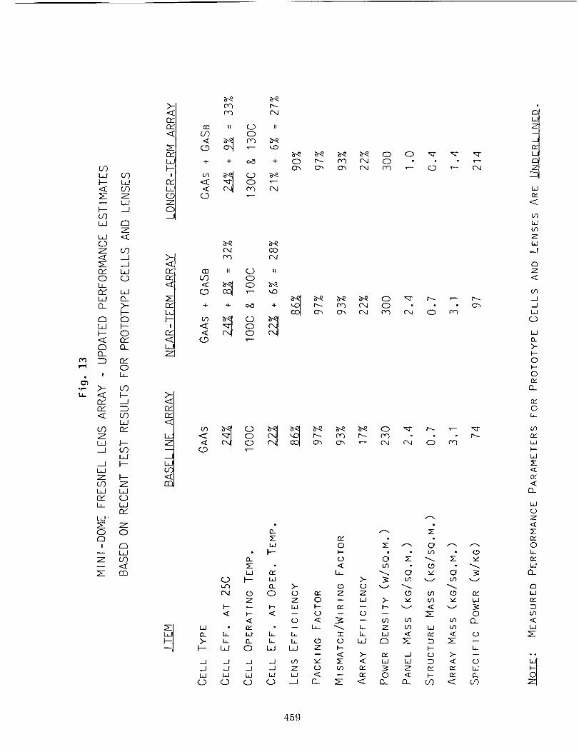
Figure 13 summarizes our latest performance estimates for the mini-dome Fresnel
lens array, based on the recent test results for prototype cells and lenses discussed
above. Using measured efficiency values for GaAs cells and mini-dome lenses, the
near-term baseline array should provide an on-orbit efficiency of 17%, corresponding
to a power density of 230 w/sq.m. As previously discussed, the baseline panel mass is
about 2.4 kg/sq.m. The previously described automatically deploying ESS structure
has a mass of 0.7 kg/sq.m., when designed to support the relatively heavy TRW MCC
concentrator panels [ref. la]. Adding this value to the panel mass provides an array
mass of 3.1 kg/sq.m., which equates to a specific power of 74 w/kg for the baseline
array.
The second column of Figure 13 corresponds to the substitution of the Boeing
MSMJ cell for the single-junction GaAs cell in the baseline panel. This single change
raises the array efficiency to 22%, the corresponding power density to 300 w/sq.m.,
and the specific power to nearly 100 w/kg. These values are based on a GaSb cell
boost efficiency of 8% (at 25C), which was achieved by Boeing earlier this year [ref.
12]. The calculated GaSb boost efficiency at operating temperature is based on an
estimated fractional power/temperature coefficient 2.3 times as high as for the GaAs
cell, to reflect the correspondingly lower open-circuit voltage of the GaSb cell (i.e.,
0.49 volts versus 1.14 volts at 25C and 100 suns).
The third column of Figure 13 includes the ultra-light panel mass reductions
discussed in a previous paragraph. In addition, the ESS structure mass estimate
has been reduced to conservatively include the effect of reduced loads due to the
drastically reduced panel mass. Also, a slight improvement in GaSb cell performance
is included, since a 9% room-temperature boost efficiency has already been measured
for GaAs-filtered cells [ref. 12]. Finally, the lens efficiency is expected to improve to
90% with the application of antireflection coatings to the lens surfaces. These small
lens and cell performance gains offset the higher cell operating temperature, to retain
the 300 w/sq.m, power density of the previous column. With the drastically reduced
mass, tile specific power increases to more than 200 w/kg.
In summary, recent prototype cell and lens test results indicate that near-term
array performance goals of 300 w/sq.m, and 100 w/kg are feasible, and that a longer-
term goal of 200 w/kg is reasonable.
448
References
[ 1.] M. J. O'Neill et al, Phase I Final Report, NASA Contract No. NAS3-24871,
ENTECH, Inc., DFW Airport, TX, (1986).
[ 2.] M. J. O'Neill and M. F. Piszczor, Proc. 8th NASA SPRAT Conference, 119
(1986).
[ 3.] M. J. O'Neill and M. F. Piszczor, Proc. 19th IEEE-PVSC, 479 (1987).
[ 4.] M. F. Piszczor and M. J. O'Neill, NASA Technical Memorandum 100101
(also presented at 22nd IECEC), (1987).
[ 5.] M. F. Piszczor and M. J. O'Neill, Proc. 9th NASA SPRAT Conference, 308
(1988).
[ 6.] M. J. O'Neill and M. F. Piszczor, Proc. 20th IEEE-PVSC(1988).
[ 7.] M. J. O'Neill, "Solar Concentrator and Energy Collection System," U.S.
Patent No. 4,069,812, 1978.
[ 8.] M. J. O'Neill, ISES/Atlanta, 531 1979.
[ 9.] M. a. O'Neill et al, ISES/Phoenix, 510 (1980).
[ 10.] M. J. O'Neill, U.S. DOE Report No. DOE/ER/80126-1 (1985).
[ 11.] M. J. O'Neill, "Photovoltaic Cell Cover for Use with a Primary Optical
Concentrator in a Solar Energy Collector," U.S. Patent No. 4,711,972 (1987).
[ 12.] J. E. Avery et al, this conference.
[ 13.] M. Mobrem, Final Report, NASA Contract No. NAS8-36043, Astro Aero-
space Corp., Carpinteria, CA (1985).
[ 14.] R. E. Patterson, Final Report, NASA Contract No. NAS8-35635, TRW,
Inc., Redondo Beach, CA (1985).
[ 15.] K. Chang, 13th Sandia Photovoltaic Concentrator Project Integration Meet-
ing (SANDS5-0791), 157 (1985).
449

Fig. I - Mini-Dome Lens Concentrator Module
OME
.SIDES
.BOl-rOMCONTACT
:DIELECTRIC
_kDIATOR
450

_JC
0..
04_fOS-
C_JU
0_J
COJ.-J
0
I0p
s--
;
i
it,.
45i

'LL
L
f,,,.
C
e"
O
C
E
I
I
&
z0I.--
z0
0I,-,-o'3
,+.4
Z
rr"
0
452
e"
,f-
I
o_
453
&
;>
Z0
_,DU-_
0_rm
09 _;.:q
o_
c.p
<0
;:_ I_>.._
.<
<
O_
454
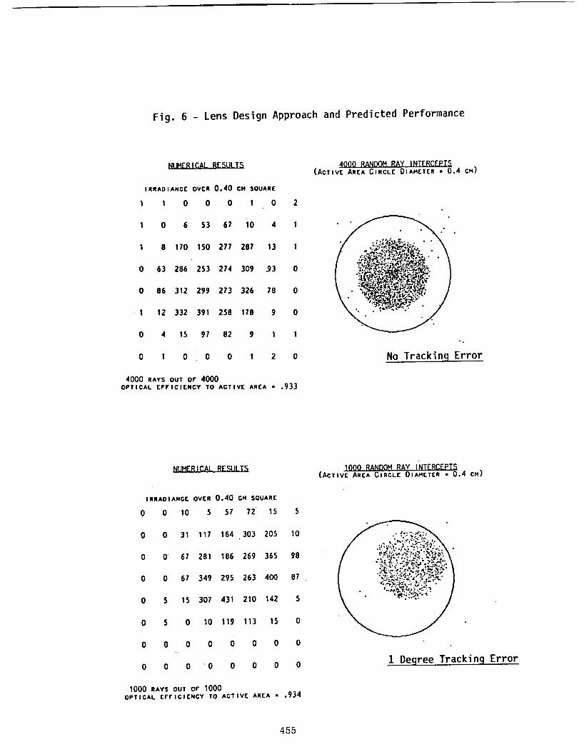
Fig. 6 - Lens Design Approach and Predicted Performance
NUMERICAL RESULTS
IRRADIANCE OVER 0,40 CM SQUARE
I I 0 0 0 I 0
I 0 6 53 G7 i0 4
1 8 110 150 277 287 13
0 G3 286 253 274 309 .93
0 86 312 299 273 326 78
1 12 332 391 256 178 9
0 4 15 97 82 9 1
0 1 0 0 0 1 2
4000 RAYS OUT OF 4000OPTICAL EFFICIENCY TO ACTIVE AREA - ,933
0
0
I
0
4000 RANDOM RAY INTERCEPTS(Active AREA CIRCLE DIAMETER • 0.4 CM)
1No Trackinq Error
NUMERICAL RESULTS
IRRAOIANC[ OVER 0.40 CM SOUAR[
0 0 10 5 57 72 15 5
0 31 117 164 303 205 10
0 67 281 186 269 365 98
0 G7 349 295 263 400 B7
0
0
0
0 $ 15 307 431 210 142 $
0 5 0 10 I19 113 15 0
0 0 0 0 0 0 0 0
0 0 0 "0 0 0 0 0
1000 RAYS OUT Or 1000OPTICAL EFFICIENCY TO ACTIVE AREA • .934
1000 RANDOM RAY INTERCEPT_(ACTIVE AREA CIRCLE DIAHETER • 0.4 CM)
1 Degree Tracking Error
455
ORIG l)",iA[. PAGE
BLACK AND WHITE PHOTOGRAP'_
Fig. 7 - Prototype Silicone Rubber Lens
Fig. 8 - Prototype Lens Focussing on Cel
456
................. @AGE _L,
OF _T_m _At.rrY
ORIGINAL PAGE
BLACK AND WHITE PHOTOGRAPH
Fig. 9 - Square Aperture Mask for Prototype Lens
Fig. 10 - Square Aperture Lens Focussing on Cell
457 OF POOR QUALITY
.TEST DI_SCR I PTION LFNS CELL GCR "_MA_ NCR OPTICALAPERTURE ACTIVE (SUNS) [fFICIENCY
S_O.CM.) S_O.CM.)
ONE-SUN RESPONSE N/A 0.126 1X 2.92" 1 100%
_ULL DOME LENS
USING 5.4 CM DIA-METER HOLE AREA
IN LENS MOUNTING
PLATFORM
22.9 0.126 182X 451" 154 85%
USING 5.5 CM OIA- 23,8METER TOTAL LENSAPERTURE AREA
0,126 189X 451" 154 81%
MASKED SOUARE LENS 13,7 0.126 I09X 214" 94 86%
(3.7 CM x 3.7 CM)
• NORMALIZED TO 1000 W/SO,M. DIRECT NORMAL INSOLATION.
Fig. 11 - Summary of Outdoor Test Results for Silicone Mini-Dome
Fresnel Lens and 1985-Vintage ASEC GaAs CassegrainianConcentrator Cell
Element
Lens Superatrate
Lens Prim
Radiator
Ce11/Cover/_fount
Roneycomb
Radiator Coating
HJ.scallaneous
TOTAL
Haterial _ Thickness Surface Area/Panel Area Hass/Panel Area
($/cu.cm.) (cm) (kg/sq.m.)
Hlcroglass 2.50 0.015 1.30 0.49
Silicone 1.00 0.015" 1.30 0.19
Al,,-in,,= 2.77 0.020 1.00 O. 55
GamAset al 5.70 0.046 0.02 0.05
Aluminum 2.77 O. 01.5 2.20 O. 91
Alumina 3.88 0.001 2.00 0.08
7.5Z of Above Total 0.1._._7
2.44
• Silicone Base Thickness - 0.010 ca
Silicone Prism Thickness - 0.01.____0ca (But Ball Void)_F[ect:Lve Silicone Th$ckness - 0.015 ca
Fig. 12 - Mass Breakdown for Baseline Mini-Dome Lens Panel
458
COI,I
<_
COW
W£)Z
Zrr_0
b_Odb30_
r-_
b3
r'h
[I_
!
&.- _--,, <_
Ct2Ct2
:7Ld-._1
-_1
COLdQdI,
L J"
0C21
I
7
Z
COLdU')ZL,.J__;
dZ}
Z<_
CO__I
__II,l
I,I13_>-I'--
0F-"0
C)_
0
CO
I--".._.I
COblC_
I--COI,I
I--
H-ibl
r.bl,irY
Z
0
C_
CO
crn
<>C_rY
Z.
l
rYLJ(._9
Z0.._I
<>CdrY<:_
rYSH-I
<:_
Z
rYrY
<:Z
LJZ
i,l
m
r_ t_
@ ar (D iiCO 0<_ _ on H
+ + o<_ +
u_ _ (D H
< r_ r'q
Oq CO
+ + c_ +
< CD
b--- r',"b C',q 0 S 0",0"_ O_ _ I-','h Oq ¢y.h
',_ 0 r-.-- r,q r--. r','h"_ 0 o",. _ ,..--
(..9 ,--
wo_
>-
w
t_
cL
z
Ld
U')t.d
7hi
---/
7
t__J_JLd
>F'-©H-©
rr©
¢YW
<
<O_
WC.)7--
©h
Wn
121W
<IM
D°
459

Workshop Summaries


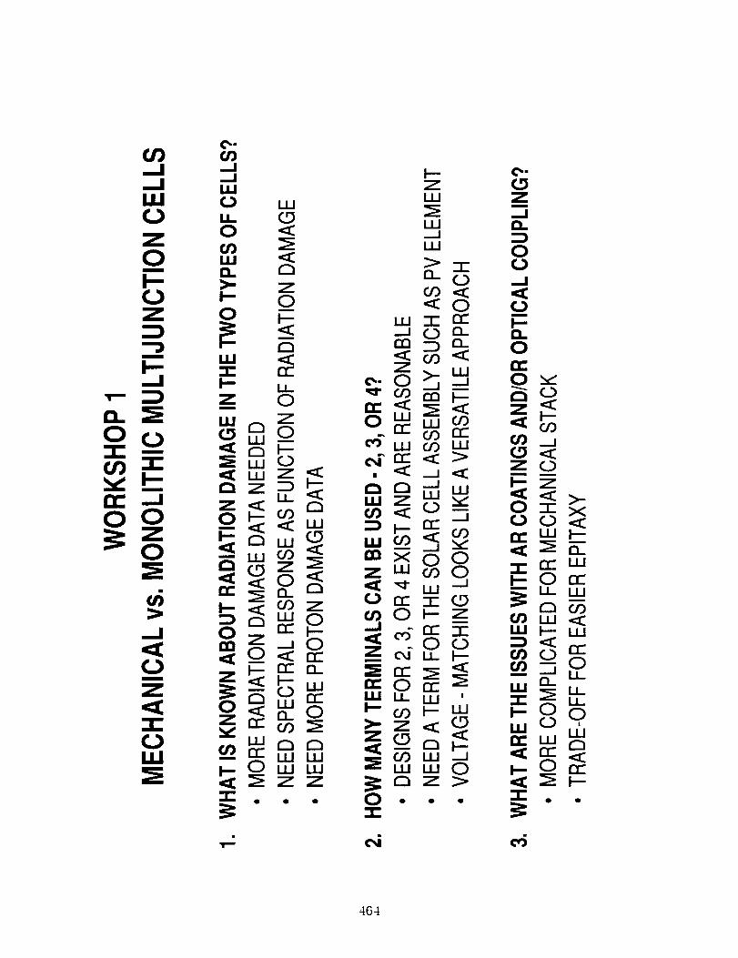
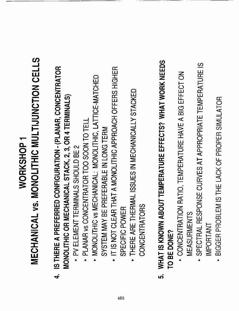
Mechanical vs. Monolithic Multijunction Cells
John Fan
Kopin Corporation
Taunton, MA
463PRF.:CEDh'q/3 _'--_E BLAi_K NOT FILMED
.,_ e,i e4
464
465

466

467

ZLU
LU._JLU
0..m
/
_J
illr_
LUNn
u.J
I-.
Ornq_
A
LUD.
mm
IN.m
rv-LU
C_
rr-
"1-C_
OZ
|
._J_.JLU
o_
ill
O
r_rv-
oi-.Zm
l.-m
LL
D
I--.mmm
r_m
D.xI.U
LUmmmm
LLm
LUa.
Oz
Imr_
CL
.J
zrr-LU
zm
468