
9100 BOSS RT - Meyer Manufacturing | Dorchester,...
80
9100 BOSS RT Truck Mounted Models 9124RT • 9126RT • 9128RT • 9130RT Trailer Models 9130T-RT • 9136T-RT • 9140T-RT PB-9100-RT Owner / Operator’s Manual & Parts Book 4 / 2017
Transcript of 9100 BOSS RT - Meyer Manufacturing | Dorchester,...
6990633 (1-13) Printed in U.S.A. © Bobcat Company 2013
9100 BOSS RTTruck Mounted Models 9124RT • 9126RT • 9128RT • 9130RT
Trailer Models 9130T-RT • 9136T-RT • 9140T-RT
PB-9100-RT
Owner / Operator’s Manual&
Parts Book
4 / 2017
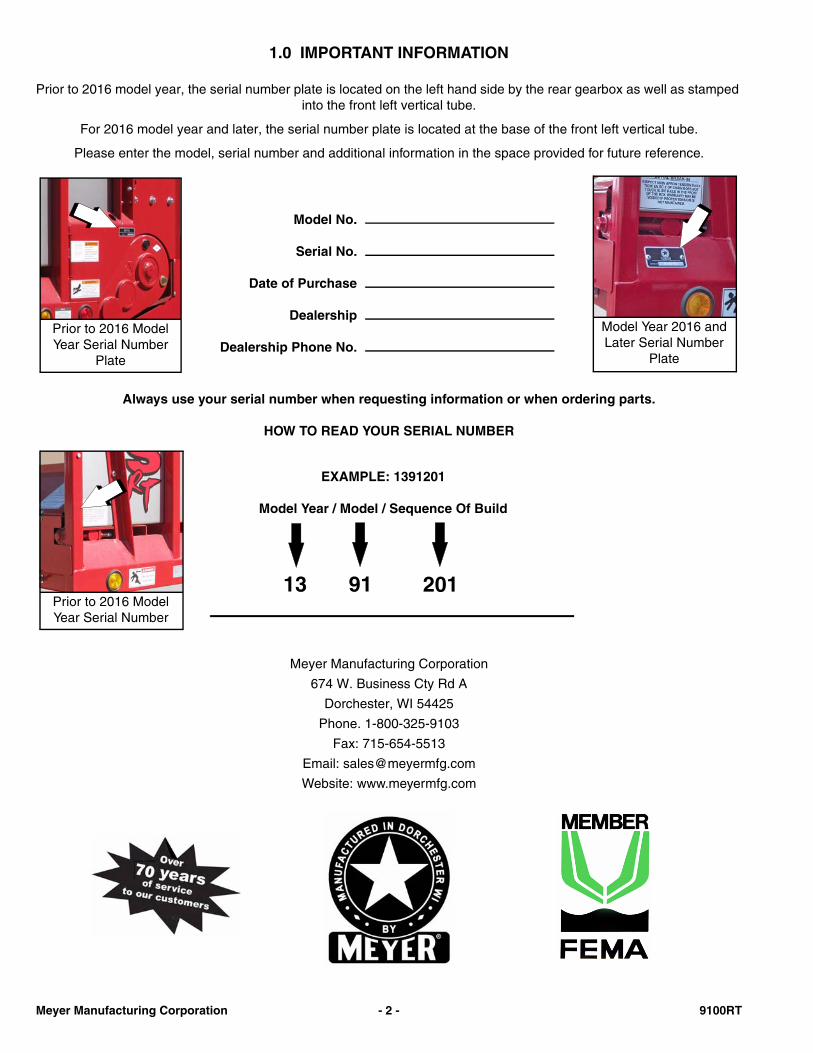
1.0 IMPORTANT INFORMATION
Prior to 2016 model year, the serial number plate is located on the left hand side by the rear gearbox as well as stamped into the front left vertical tube.
For 2016 model year and later, the serial number plate is located at the base of the front left vertical tube.
Please enter the model, serial number and additional information in the space provided for future reference.
Always use your serial number when requesting information or when ordering parts.
HOW TO READ YOUR SERIAL NUMBER
Meyer Manufacturing Corporation
674 W. Business Cty Rd A
Dorchester, WI 54425
Phone. 1-800-325-9103
Fax: 715-654-5513
Email: [email protected]
Website: www.meyermfg.com
Model No.
Serial No.
Date of Purchase
Dealership
Dealership Phone No.
Model Year 2016 and Later Serial Number
Plate
Prior to 2016 Model Year Serial Number
Plate
EXAMPLE: 1391201
Model Year / Model / Sequence Of Build
13 91 201Prior to 2016 Model Year Serial Number
Meyer Manufacturing Corporation - 2 - 9100RT
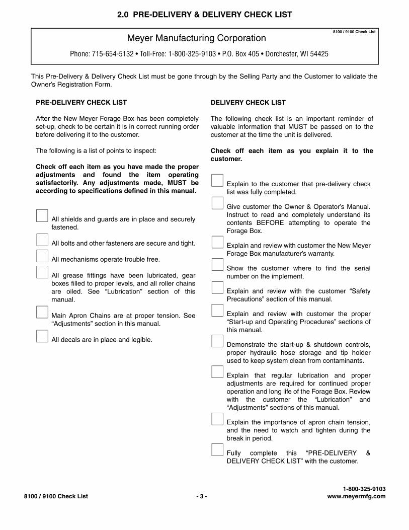
2.0 PRE-DELIVERY & DELIVERY CHECK LIST
This Pre-Delivery & Delivery Check List must be gone through by the Selling Party and the Customer to validate theOwner’s Registration Form.
Meyer Manufacturing Corporation
Phone: 715-654-5132 • Toll-Free: 1-800-325-9103 • P.O. Box 405 • Dorchester, WI 54425
8100 / 9100 Check List
All shields and guards are in place and securelyfastened.
All bolts and other fasteners are secure and tight.
All mechanisms operate trouble free.
All grease fittings have been lubricated, gearboxes filled to proper levels, and all roller chainsare oiled. See “Lubrication” section of thismanual.
Main Apron Chains are at proper tension. See“Adjustments” section in this manual.
All decals are in place and legible.
PRE-DELIVERY CHECK LIST
After the New Meyer Forage Box has been completelyset-up, check to be certain it is in correct running orderbefore delivering it to the customer.
The following is a list of points to inspect:
Check off each item as you have made the properadjustments and found the item operatingsatisfactorily. Any adjustments made, MUST beaccording to specifications defined in this manual.
DELIVERY CHECK LIST
The following check list is an important reminder ofvaluable information that MUST be passed on to thecustomer at the time the unit is delivered.
Check off each item as you explain it to thecustomer.
Explain to the customer that pre-delivery checklist was fully completed.
Give customer the Owner & Operator’s Manual.Instruct to read and completely understand itscontents BEFORE attempting to operate theForage Box.
Explain and review with customer the New MeyerForage Box manufacturer’s warranty.
Show the customer where to find the serialnumber on the implement.
Explain and review with the customer “SafetyPrecautions” section of this manual.
Explain and review with customer the proper“Start-up and Operating Procedures” sections ofthis manual.
Demonstrate the start-up & shutdown controls,proper hydraulic hose storage and tip holderused to keep system clean from contaminants.
Explain that regular lubrication and properadjustments are required for continued properoperation and long life of the Forage Box. Reviewwith the customer the “Lubrication” and“Adjustments” sections of this manual.
Explain the importance of apron chain tension,and the need to watch and tighten during thebreak in period.
Fully complete this “PRE-DELIVERY &DELIVERY CHECK LIST” with the customer.
1-800-325-91038100 / 9100 Check List - 3 - www.meyermfg.com
Meyer Manufacturing Corporation674 W. Business Cty Rd A
Dorchester, WI 54425Phone: 1-800-325-9103
Fax: 715-654-5513Email: [email protected]: www.meyermfg.com
FARM EQUIPMENT BUYERS TRUST THE NAME MEYER!
Meyer Manufacturing Corporation - 4 - 9100RT
3.0 INTRODUCTION
Congratulations on your purchase of a new Meyer farm equipment product. Undoubtedly you have givenmuch consideration to your purchase and we’re proud that you have selected Meyer. Pride in craftsmanship,engineering and customer service have made Meyer products the finest in the farm equipment industry today.
There is no substitute for quality. That is why thousands of people like you have purchased Meyer farmequipment. They felt it was the best equipment to serve their farming needs, now and in years to come. Weask that you follow our policy of “safety first”, and we strongly suggest that you read through the “Owner /Operator’s Manual & Parts Book” before operating your Meyer farm equipment. Meyer ManufacturingCorporation wants to thank you for not compromising quality. We are determined to offer excellence incustomer service as well as provide you with the very best value for your dollar.
Sincerely,
All Employees ofMEYER MANUFACTURING CORPORATION
The Model 9100-RT is available as a semi - trailer, truck mounted unit or mounted to an ag cart or wagon running gearpulled and powered by a farm tractor.
When the PTO is referred to, it means power takeoff from the truck.
The Model 9100-RT may be referred to as rear unload box, forage box, or rear unload forage box in this manual.
Manufacturer’s Statement: Meyer Manufacturing Corporation reserves the right to make improvements in design, orchanges in specifications at any time, without incurring any obligation to owners of units previously sold. This supersedesall previous published instructions.
IMPORTANT: You are urged to study this manual and follow the instructions carefully. Your efforts will berepaid in better operation and service as well as a savings in time and repair expense. Failure to read thismanual and understand the machine could lead to serious injury. If you do not understand instructions inthis manual, contact either your dealer or Meyer Manufacturing Corp. at Dorchester, WI 54425.
WARRANTY: At the front of this manual is an “Owner's Registration Form”. Be sure your dealer hascompleted this form and promptly forwarded a copy to Meyer Manufacturing to validate the manufacturer’swarranty. The product model and serial number are recorded on this form and on the inside of the frontcover for proper identification of your Meyer Forage Box by your dealer and the manufacturer whenordering repair parts. The serial number is stamped in the front upright of the left-hand side.
REPAIR PARTS: At the back of this manual is the repair parts section. All replacement parts are to beobtained from or ordered through your Meyer dealership. When ordering repair parts, refer to the partssection and give complete information including quantity, correct part number, detailed description andeven model and serial numbers of the forage box which needs repair parts.
1-800-325-91039100RT - 5 - www.meyermfg.com
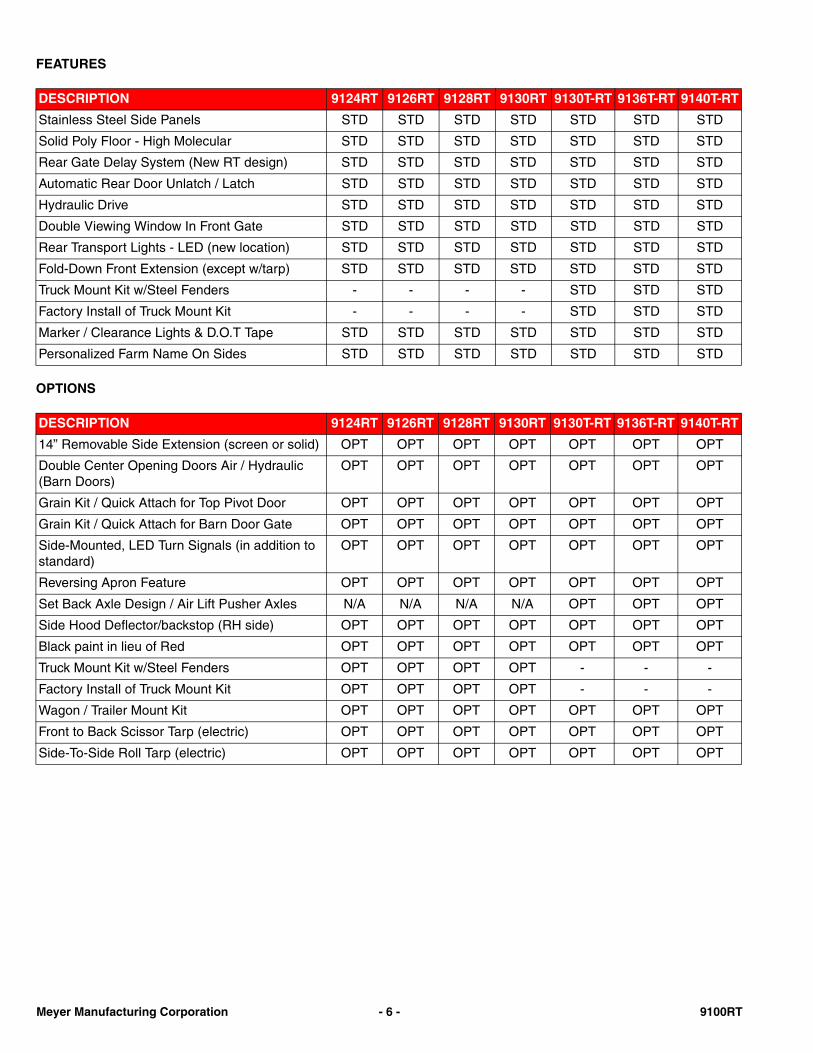
FEATURES
OPTIONS
DESCRIPTION 9124RT 9126RT 9128RT 9130RT 9130T-RT 9136T-RT 9140T-RT
Stainless Steel Side Panels STD STD STD STD STD STD STD
Solid Poly Floor - High Molecular STD STD STD STD STD STD STD
Rear Gate Delay System (New RT design) STD STD STD STD STD STD STD
Automatic Rear Door Unlatch / Latch STD STD STD STD STD STD STD
Hydraulic Drive STD STD STD STD STD STD STD
Double Viewing Window In Front Gate STD STD STD STD STD STD STD
Rear Transport Lights - LED (new location) STD STD STD STD STD STD STD
Fold-Down Front Extension (except w/tarp) STD STD STD STD STD STD STD
Truck Mount Kit w/Steel Fenders - - - - STD STD STD
Factory Install of Truck Mount Kit - - - - STD STD STD
Marker / Clearance Lights & D.O.T Tape STD STD STD STD STD STD STD
Personalized Farm Name On Sides STD STD STD STD STD STD STD
DESCRIPTION 9124RT 9126RT 9128RT 9130RT 9130T-RT 9136T-RT 9140T-RT
14” Removable Side Extension (screen or solid) OPT OPT OPT OPT OPT OPT OPT
Double Center Opening Doors Air / Hydraulic (Barn Doors)
OPT OPT OPT OPT OPT OPT OPT
Grain Kit / Quick Attach for Top Pivot Door OPT OPT OPT OPT OPT OPT OPT
Grain Kit / Quick Attach for Barn Door Gate OPT OPT OPT OPT OPT OPT OPT
Side-Mounted, LED Turn Signals (in addition to standard)
OPT OPT OPT OPT OPT OPT OPT
Reversing Apron Feature OPT OPT OPT OPT OPT OPT OPT
Set Back Axle Design / Air Lift Pusher Axles N/A N/A N/A N/A OPT OPT OPT
Side Hood Deflector/backstop (RH side) OPT OPT OPT OPT OPT OPT OPT
Black paint in lieu of Red OPT OPT OPT OPT OPT OPT OPT
Truck Mount Kit w/Steel Fenders OPT OPT OPT OPT - - -
Factory Install of Truck Mount Kit OPT OPT OPT OPT - - -
Wagon / Trailer Mount Kit OPT OPT OPT OPT OPT OPT OPT
Front to Back Scissor Tarp (electric) OPT OPT OPT OPT OPT OPT OPT
Side-To-Side Roll Tarp (electric) OPT OPT OPT OPT OPT OPT OPT
Meyer Manufacturing Corporation - 6 - 9100RT
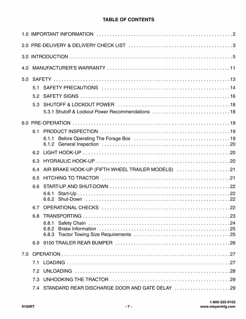
TABLE OF CONTENTS
1.0 IMPORTANT INFORMATION . . . . . . . . . . . . . . . . . . . . . . . . . . . . . . . . . . . . . . . . . . . . . . . . . . . 2
2.0 PRE-DELIVERY & DELIVERY CHECK LIST . . . . . . . . . . . . . . . . . . . . . . . . . . . . . . . . . . . . . . . 3
3.0 INTRODUCTION . . . . . . . . . . . . . . . . . . . . . . . . . . . . . . . . . . . . . . . . . . . . . . . . . . . . . . . . . . . . .5
4.0 MANUFACTURER’S WARRANTY . . . . . . . . . . . . . . . . . . . . . . . . . . . . . . . . . . . . . . . . . . . . . .11
5.0 SAFETY . . . . . . . . . . . . . . . . . . . . . . . . . . . . . . . . . . . . . . . . . . . . . . . . . . . . . . . . . . . . . . . . . . 13
5.1 SAFETY PRECAUTIONS . . . . . . . . . . . . . . . . . . . . . . . . . . . . . . . . . . . . . . . . . . . . . . . . 14
5.2 SAFETY SIGNS . . . . . . . . . . . . . . . . . . . . . . . . . . . . . . . . . . . . . . . . . . . . . . . . . . . . . . . . 16
5.3 SHUTOFF & LOCKOUT POWER . . . . . . . . . . . . . . . . . . . . . . . . . . . . . . . . . . . . . . . . . .18
5.3.1 Shutoff & Lockout Power Recommendations . . . . . . . . . . . . . . . . . . . . . . . . . . . . . 18
6.0 PRE-OPERATION . . . . . . . . . . . . . . . . . . . . . . . . . . . . . . . . . . . . . . . . . . . . . . . . . . . . . . . . . . . 19
6.1 PRODUCT INSPECTION . . . . . . . . . . . . . . . . . . . . . . . . . . . . . . . . . . . . . . . . . . . . . . . . . 19
6.1.1 Before Operating The Forage Box . . . . . . . . . . . . . . . . . . . . . . . . . . . . . . . . . . . . 196.1.2 General Inspection . . . . . . . . . . . . . . . . . . . . . . . . . . . . . . . . . . . . . . . . . . . . . . . . 20
6.2 LIGHT HOOK-UP . . . . . . . . . . . . . . . . . . . . . . . . . . . . . . . . . . . . . . . . . . . . . . . . . . . . . . . 20
6.3 HYDRAULIC HOOK-UP . . . . . . . . . . . . . . . . . . . . . . . . . . . . . . . . . . . . . . . . . . . . . . . . . . 20
6.4 AIR BRAKE HOOK-UP (FIFTH WHEEL TRAILER MODELS) . . . . . . . . . . . . . . . . . . . . 21
6.5 HITCHING TO TRACTOR . . . . . . . . . . . . . . . . . . . . . . . . . . . . . . . . . . . . . . . . . . . . . . . . 21
6.6 START-UP AND SHUT-DOWN . . . . . . . . . . . . . . . . . . . . . . . . . . . . . . . . . . . . . . . . . . . . . 22
6.6.1 Start-Up . . . . . . . . . . . . . . . . . . . . . . . . . . . . . . . . . . . . . . . . . . . . . . . . . . . . . . . . . 226.6.2 Shut-Down . . . . . . . . . . . . . . . . . . . . . . . . . . . . . . . . . . . . . . . . . . . . . . . . . . . . . . 22
6.7 OPERATIONAL CHECKS . . . . . . . . . . . . . . . . . . . . . . . . . . . . . . . . . . . . . . . . . . . . . . . . 22
6.8 TRANSPORTING . . . . . . . . . . . . . . . . . . . . . . . . . . . . . . . . . . . . . . . . . . . . . . . . . . . . . . . 23
6.8.1 Safety Chain . . . . . . . . . . . . . . . . . . . . . . . . . . . . . . . . . . . . . . . . . . . . . . . . . . . . . 246.8.2 Brake Information . . . . . . . . . . . . . . . . . . . . . . . . . . . . . . . . . . . . . . . . . . . . . . . . .256.8.3 Tractor Towing Size Requirements . . . . . . . . . . . . . . . . . . . . . . . . . . . . . . . . . . . . 25
6.9 9100 TRAILER REAR BUMPER . . . . . . . . . . . . . . . . . . . . . . . . . . . . . . . . . . . . . . . . . . . 26
7.0 OPERATION . . . . . . . . . . . . . . . . . . . . . . . . . . . . . . . . . . . . . . . . . . . . . . . . . . . . . . . . . . . . . . . 27
7.1 LOADING . . . . . . . . . . . . . . . . . . . . . . . . . . . . . . . . . . . . . . . . . . . . . . . . . . . . . . . . . . . . . 27
7.2 UNLOADING . . . . . . . . . . . . . . . . . . . . . . . . . . . . . . . . . . . . . . . . . . . . . . . . . . . . . . . . . . 28
7.3 UNHOOKING THE TRACTOR . . . . . . . . . . . . . . . . . . . . . . . . . . . . . . . . . . . . . . . . . . . . . 29
7.4 STANDARD REAR DISCHARGE DOOR AND GATE DELAY . . . . . . . . . . . . . . . . . . . . . 29
1-800-325-91039100RT - 7 - www.meyermfg.com
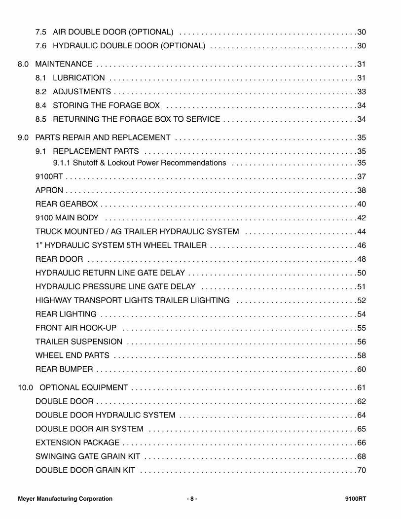
7.5 AIR DOUBLE DOOR (OPTIONAL) . . . . . . . . . . . . . . . . . . . . . . . . . . . . . . . . . . . . . . . . .30
7.6 HYDRAULIC DOUBLE DOOR (OPTIONAL) . . . . . . . . . . . . . . . . . . . . . . . . . . . . . . . . . .30
8.0 MAINTENANCE . . . . . . . . . . . . . . . . . . . . . . . . . . . . . . . . . . . . . . . . . . . . . . . . . . . . . . . . . . . .31
8.1 LUBRICATION . . . . . . . . . . . . . . . . . . . . . . . . . . . . . . . . . . . . . . . . . . . . . . . . . . . . . . . . .31
8.2 ADJUSTMENTS . . . . . . . . . . . . . . . . . . . . . . . . . . . . . . . . . . . . . . . . . . . . . . . . . . . . . . . .33
8.4 STORING THE FORAGE BOX . . . . . . . . . . . . . . . . . . . . . . . . . . . . . . . . . . . . . . . . . . . .34
8.5 RETURNING THE FORAGE BOX TO SERVICE . . . . . . . . . . . . . . . . . . . . . . . . . . . . . . .34
9.0 PARTS REPAIR AND REPLACEMENT . . . . . . . . . . . . . . . . . . . . . . . . . . . . . . . . . . . . . . . . . .35
9.1 REPLACEMENT PARTS . . . . . . . . . . . . . . . . . . . . . . . . . . . . . . . . . . . . . . . . . . . . . . . . .35
9.1.1 Shutoff & Lockout Power Recommendations . . . . . . . . . . . . . . . . . . . . . . . . . . . . .35
9100RT . . . . . . . . . . . . . . . . . . . . . . . . . . . . . . . . . . . . . . . . . . . . . . . . . . . . . . . . . . . . . . . . . . .37
APRON . . . . . . . . . . . . . . . . . . . . . . . . . . . . . . . . . . . . . . . . . . . . . . . . . . . . . . . . . . . . . . . . . . .38
REAR GEARBOX . . . . . . . . . . . . . . . . . . . . . . . . . . . . . . . . . . . . . . . . . . . . . . . . . . . . . . . . . . .40
9100 MAIN BODY . . . . . . . . . . . . . . . . . . . . . . . . . . . . . . . . . . . . . . . . . . . . . . . . . . . . . . . . . .42
TRUCK MOUNTED / AG TRAILER HYDRAULIC SYSTEM . . . . . . . . . . . . . . . . . . . . . . . . . .44
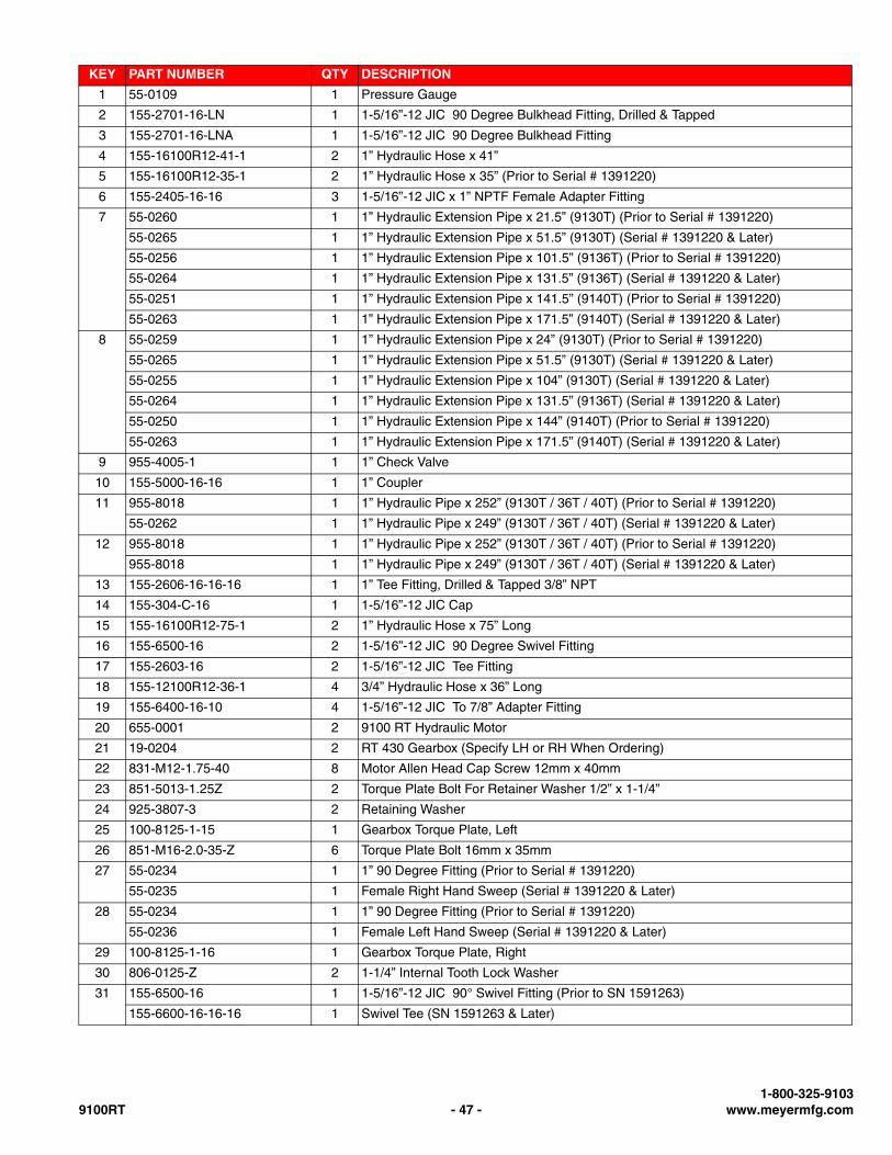
1” HYDRAULIC SYSTEM 5TH WHEEL TRAILER . . . . . . . . . . . . . . . . . . . . . . . . . . . . . . . . . .46
REAR DOOR . . . . . . . . . . . . . . . . . . . . . . . . . . . . . . . . . . . . . . . . . . . . . . . . . . . . . . . . . . . . . .48
HYDRAULIC RETURN LINE GATE DELAY . . . . . . . . . . . . . . . . . . . . . . . . . . . . . . . . . . . . . . .50
HYDRAULIC PRESSURE LINE GATE DELAY . . . . . . . . . . . . . . . . . . . . . . . . . . . . . . . . . . . .51
HIGHWAY TRANSPORT LIGHTS TRAILER LIIGHTING . . . . . . . . . . . . . . . . . . . . . . . . . . . .52
REAR LIGHTING . . . . . . . . . . . . . . . . . . . . . . . . . . . . . . . . . . . . . . . . . . . . . . . . . . . . . . . . . . .54
FRONT AIR HOOK-UP . . . . . . . . . . . . . . . . . . . . . . . . . . . . . . . . . . . . . . . . . . . . . . . . . . . . . .55
TRAILER SUSPENSION . . . . . . . . . . . . . . . . . . . . . . . . . . . . . . . . . . . . . . . . . . . . . . . . . . . . .56
WHEEL END PARTS . . . . . . . . . . . . . . . . . . . . . . . . . . . . . . . . . . . . . . . . . . . . . . . . . . . . . . . .58
REAR BUMPER . . . . . . . . . . . . . . . . . . . . . . . . . . . . . . . . . . . . . . . . . . . . . . . . . . . . . . . . . . . .60
10.0 OPTIONAL EQUIPMENT . . . . . . . . . . . . . . . . . . . . . . . . . . . . . . . . . . . . . . . . . . . . . . . . . . . .61
DOUBLE DOOR . . . . . . . . . . . . . . . . . . . . . . . . . . . . . . . . . . . . . . . . . . . . . . . . . . . . . . . . . . . .62
DOUBLE DOOR HYDRAULIC SYSTEM . . . . . . . . . . . . . . . . . . . . . . . . . . . . . . . . . . . . . . . . .64
DOUBLE DOOR AIR SYSTEM . . . . . . . . . . . . . . . . . . . . . . . . . . . . . . . . . . . . . . . . . . . . . . . .65
EXTENSION PACKAGE . . . . . . . . . . . . . . . . . . . . . . . . . . . . . . . . . . . . . . . . . . . . . . . . . . . . . .66
SWINGING GATE GRAIN KIT . . . . . . . . . . . . . . . . . . . . . . . . . . . . . . . . . . . . . . . . . . . . . . . . .68
DOUBLE DOOR GRAIN KIT . . . . . . . . . . . . . . . . . . . . . . . . . . . . . . . . . . . . . . . . . . . . . . . . . .70
Meyer Manufacturing Corporation - 8 - 9100RT
DUAL DRIVE 3/4” FLOW CONTROL SYSTEM TRUCK MOUNT AND AG CART UNDERCARRIAGE . . . . . . . . . . . . . . . . . . . . . . . . . . . . . . . . . . . . . . . . . . . . . . . . . . . . . . . . . 72
DUAL DRIVE 1” FLOW CONTROL SYSTEM 5TH WHEEL AG TRAILER . . . . . . . . . . . . . . . 73
TRUCK MOUNT FENDER AND MUD FLAP . . . . . . . . . . . . . . . . . . . . . . . . . . . . . . . . . . . . . . 74
11.0 SPECIFICATIONS . . . . . . . . . . . . . . . . . . . . . . . . . . . . . . . . . . . . . . . . . . . . . . . . . . . . . . . . . . 75
11.1 9100 TRAILER TIRE WHEEL TORQUE . . . . . . . . . . . . . . . . . . . . . . . . . . . . . . . . . . . . 76
11.1.1 Wheel Torque Chart . . . . . . . . . . . . . . . . . . . . . . . . . . . . . . . . . . . . . . . . . . . . . . 7611.1.2 Tire Inflation Chart . . . . . . . . . . . . . . . . . . . . . . . . . . . . . . . . . . . . . . . . . . . . . . . 76
MAINTENANCE RECORD . . . . . . . . . . . . . . . . . . . . . . . . . . . . . . . . . . . . . . . . . . . . . . . . . . . . . . . . 79
1-800-325-91039100RT - 9 - www.meyermfg.com

Meyer Manufacturing Corporation - 10 - 9100RT
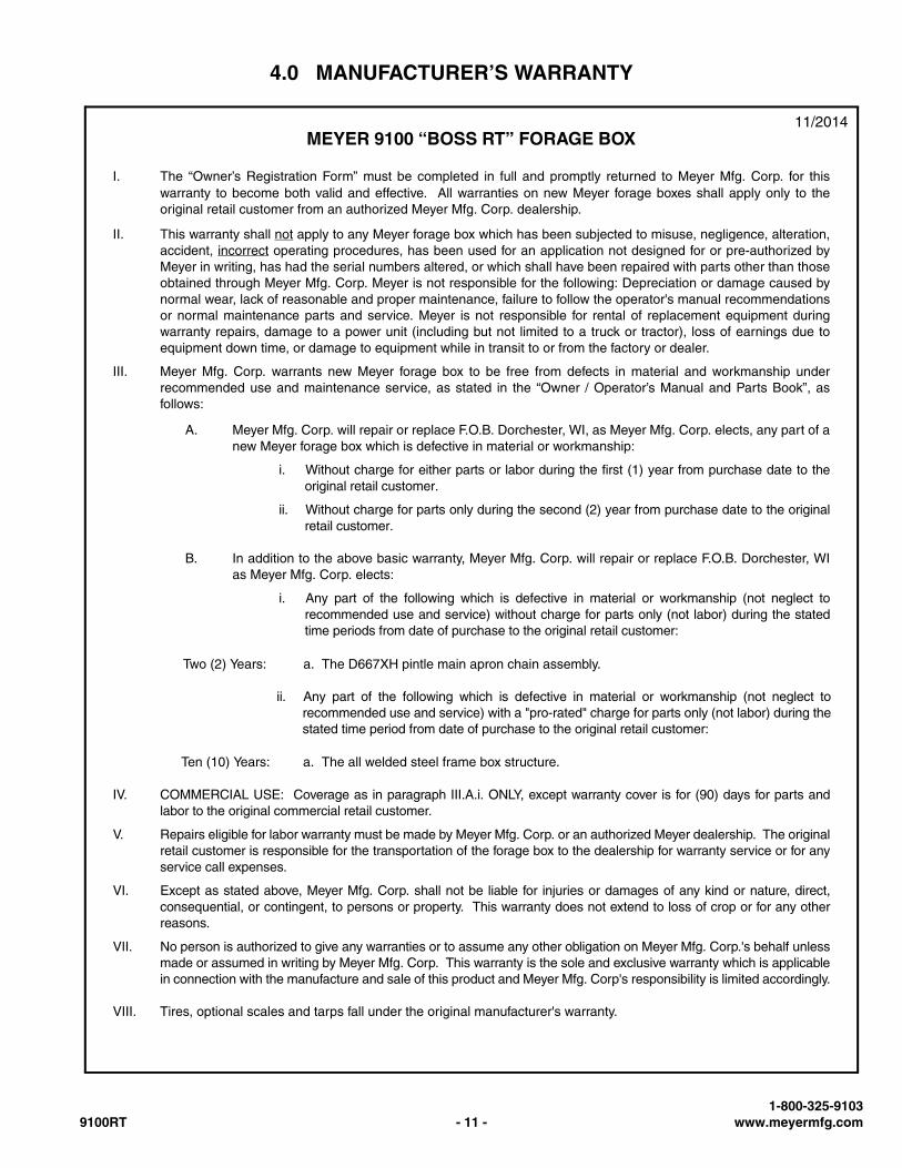
4.0 MANUFACTURER’S WARRANTY
MEYER 9100 “BOSS RT” FORAGE BOX11/2014
I. The “Owner’s Registration Form” must be completed in full and promptly returned to Meyer Mfg. Corp. for thiswarranty to become both valid and effective. All warranties on new Meyer forage boxes shall apply only to theoriginal retail customer from an authorized Meyer Mfg. Corp. dealership.
II. This warranty shall not apply to any Meyer forage box which has been subjected to misuse, negligence, alteration,accident, incorrect operating procedures, has been used for an application not designed for or pre-authorized byMeyer in writing, has had the serial numbers altered, or which shall have been repaired with parts other than thoseobtained through Meyer Mfg. Corp. Meyer is not responsible for the following: Depreciation or damage caused bynormal wear, lack of reasonable and proper maintenance, failure to follow the operator's manual recommendationsor normal maintenance parts and service. Meyer is not responsible for rental of replacement equipment duringwarranty repairs, damage to a power unit (including but not limited to a truck or tractor), loss of earnings due toequipment down time, or damage to equipment while in transit to or from the factory or dealer.
III. Meyer Mfg. Corp. warrants new Meyer forage box to be free from defects in material and workmanship underrecommended use and maintenance service, as stated in the “Owner / Operator’s Manual and Parts Book”, asfollows:
A. Meyer Mfg. Corp. will repair or replace F.O.B. Dorchester, WI, as Meyer Mfg. Corp. elects, any part of anew Meyer forage box which is defective in material or workmanship:
i. Without charge for either parts or labor during the first (1) year from purchase date to theoriginal retail customer.
ii. Without charge for parts only during the second (2) year from purchase date to the originalretail customer.
B. In addition to the above basic warranty, Meyer Mfg. Corp. will repair or replace F.O.B. Dorchester, WIas Meyer Mfg. Corp. elects:
i. Any part of the following which is defective in material or workmanship (not neglect torecommended use and service) without charge for parts only (not labor) during the statedtime periods from date of purchase to the original retail customer:
IV. COMMERCIAL USE: Coverage as in paragraph III.A.i. ONLY, except warranty cover is for (90) days for parts andlabor to the original commercial retail customer.
V. Repairs eligible for labor warranty must be made by Meyer Mfg. Corp. or an authorized Meyer dealership. The originalretail customer is responsible for the transportation of the forage box to the dealership for warranty service or for anyservice call expenses.
VI. Except as stated above, Meyer Mfg. Corp. shall not be liable for injuries or damages of any kind or nature, direct,consequential, or contingent, to persons or property. This warranty does not extend to loss of crop or for any otherreasons.
VII. No person is authorized to give any warranties or to assume any other obligation on Meyer Mfg. Corp.'s behalf unlessmade or assumed in writing by Meyer Mfg. Corp. This warranty is the sole and exclusive warranty which is applicablein connection with the manufacture and sale of this product and Meyer Mfg. Corp's responsibility is limited accordingly.
VIII. Tires, optional scales and tarps fall under the original manufacturer's warranty.
Two (2) Years: a. The D667XH pintle main apron chain assembly.
ii. Any part of the following which is defective in material or workmanship (not neglect torecommended use and service) with a "pro-rated" charge for parts only (not labor) during thestated time period from date of purchase to the original retail customer:
Ten (10) Years: a. The all welded steel frame box structure.
1-800-325-91039100RT - 11 - www.meyermfg.com

Meyer Manufacturing Corporation - 12 - 9100RT
5.0 SAFETY
The Meyer Forage Box is manufactured with operator safety in mind. Located on the forage box are various safety signsto aid in operation and warn of hazardous areas. Pay close attention to all safety signs on the forage box.
Carefully follow the operating and maintenance instructions in this manual and all applicable safety laws. Failure to followall safety procedures may result in serious injury or death.
Before attempting to operate this forage box, read and study the following safety information. In addition, makesure that every individual who operates or works with the forage box, whether family member or employee, isfamiliar with these safety precautions.
Meyer Mfg. Corp. provides guards for exposed moving parts for the operator’s protection; however, some areascannot be guarded or shielded in order to assure proper operation. The operator’s manual and safety signs onthe forage box itself warn you of hazards and must be read and observed closely!
Danger, Warning, Caution, and instructional decals and plates are placed on the equipment to protect anyone working onor around this machine, as well as the components of the machine. All personnel operating or maintaining this equipmentmust familiarize themselves with all Danger, Warning, Caution, and instructional decals and plates.
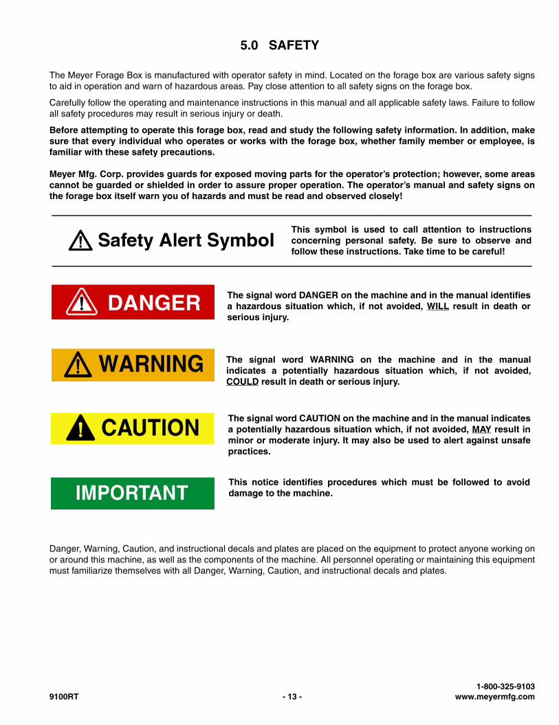
This symbol is used to call attention to instructionsconcerning personal safety. Be sure to observe andfollow these instructions. Take time to be careful!
The signal word DANGER on the machine and in the manual identifiesa hazardous situation which, if not avoided, WILL result in death orserious injury.
The signal word WARNING on the machine and in the manualindicates a potentially hazardous situation which, if not avoided,COULD result in death or serious injury.
The signal word CAUTION on the machine and in the manual indicatesa potentially hazardous situation which, if not avoided, MAY result inminor or moderate injury. It may also be used to alert against unsafepractices.
This notice identifies procedures which must be followed to avoiddamage to the machine.
1-800-325-91039100RT - 13 - www.meyermfg.com
5.1 SAFETY PRECAUTIONS
• DO NOT allow anyone to operate, service, inspect or otherwise handle this forage box until all operators have readand understood all of the instructional materials in this Operator’s And Parts Manual and have been properly trainedin its intended usage.
• For an operator to be qualified, he or she must not use drugs or alcohol which impair alertness or coordination whileworking. An operator who is taking prescription drugs must get medical advice to determine if he or she can safelyoperate a machine and the equipment.
• Make sure all personnel can READ and UNDERSTAND all safety signs.
• DO NOT allow minors (children) or inexperienced persons to operate this forage box.
• DO NOT operate until all shields and guards are in place and securely fastened.
• DO NOT step up on any part of the forage box at any time.
• DO NOT adjust, clean or lubricate while the forage box is in motion.
• Inspect when first delivered and regularly thereafter; that all connections and bolts are tight and secure beforeoperating.
• Know how to stop operation of the forage box before starting it!
• Make certain everyone is clear of the forage box before applying power.
• Keep hands, feet and clothing away from moving parts. Loose or floppy clothing should not be worn by the operator.
• Observe all applicable traffic laws when transporting on public roadways (where legal to do so). Check local laws forall highway lighting and marking requirements.
• Shut off and lock out power before adjusting, servicing, maintaining or clearing an obstruction from this machine. (See5.3 SHUTOFF & LOCKOUT POWER on page 18.)
• Always enter curves or drive up or down hills at a low speed and at a gradual steering angle.
• Never allow riders on either tractor / truck or equipment.
• Keep tractor / truck in a lower gear at all times when traveling down steep grades.
• Maintain proper brake settings at all times (if equipped).
• Stay away from overhead power lines. Electrocution can occur without direct contact.
• Use only properly rated undercarriage and tires.
All individuals who will operate this Forage Box must readand completely understand this Operator’s And PartsManual. Operator must have instructions before operatingthe machine. Untrained operators can cause injury or death.
Meyer Manufacturing Corporation - 14 - 9100RT
Safety Precautions For Tractor Towed Units:
• Do not exceed 20 mph (32 kph). Reduce speed on rough roads and surfaces.
• Always install a SMV emblem on pull-type equipment when transporting on roadways and keep clean and bright.
• Always yield to oncoming traffic in all situations and move to the side of the road so any following traffic may pass.
Safety Precautions For Truck Mounted & Fifth Wheel Trailer Units:
• Comply with state and local laws governing highway safety and movement of machinery on roadways.
Safety Precautions For Hydraulic System:
• Check hydraulic tubes, hoses and fittings for damage and leakage. Never use hands to check for leaks. Hydraulictubes and hoses must be properly routed and have adequate support and secure clamps. Tighten or replace any partsthat show leakage.
• Always clean fluid spills. Do not use gasoline or diesel fuel for cleaning parts. Use commercial nonflammable solvents.
1-800-325-91039100RT - 15 - www.meyermfg.com
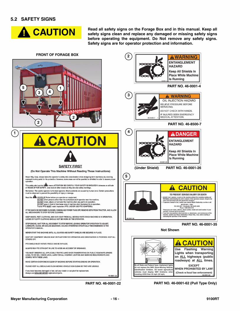
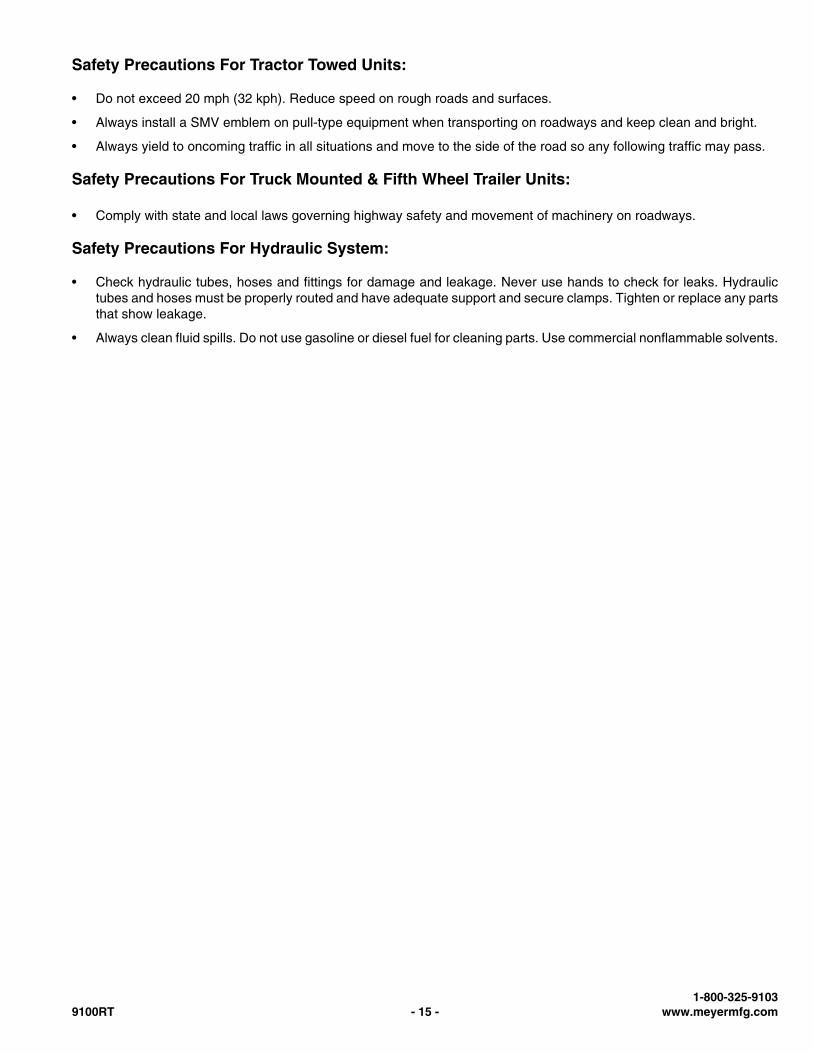
5.2 SAFETY SIGNS
Read all safety signs on the Forage Box and in this manual. Keep allsafety signs clean and replace any damaged or missing safety signsbefore operating the equipment. Do Not remove any safety signs.Safety signs are for operator protection and information.
1
22
35
4
1
PART NO. 46-0001-35
PART NO. 46-8500-7
PART NO. 46-0001-4
2
3
4
PART NO. 46-0001-22
FRONT OF FORAGE BOX
PART NO. 46-0001-62 (Pull Type Only)
Not Shown
5
PART NO. 46-0001-26(Under Shield)
Meyer Manufacturing Corporation - 16 - 9100RT
4 4 4
33
5
1
1
PART NO. 46-0011-D
PART NO. 46-9100-3
REAR OF FORAGE BOX
SIDE OF FORAGE BOX
PART NO. 46-9100-4
PART NO. 46-0001-20
4
3 5
1-800-325-91039100RT - 17 - www.meyermfg.com
5.3 SHUTOFF & LOCKOUT POWER
Any individual that will be adjusting, servicing, maintaining, or clearing an obstruction from this machine needsto ensure that this machine stays safely “OFF” until the adjustment, service, or maintenance has beencompleted, or when the obstruction has been cleared, and that all guards, shields, and covers have beenrestored to their original position. The safety of all individuals working on or around this machine, includingfamily members, are affected. The following procedure will be referred to throughout this manual, so be familiarwith the following steps.
5.3.1 Shutoff & Lockout Power Recommendations
1. Think, Plan and Check
a. Think through the entire procedure and identify all the steps that are required.
b. Plan what personnel will be involved, what needs to be shut down, what guards / shields need to be removed, andhow the equipment will be restarted.
c. Check the machine over to verify all power sources and stored energy have been identified including engines,hydraulic and pneumatic systems, springs and accumulators, and suspended loads.
2. Communicate - Let everyone involved, including those working on or around this machine, that work is being donewhich involves keeping this machine safely “OFF”.
3. Power Sources
a. LOCKOUT - Shut off engines and take the key, or physically lock the start/on switch or control. Disconnect anypower sources which are meant to be disconnected (i.e. electrical, hydraulic, and PTO of pull-type units).
b. TAGOUT - Place a tag on the machine noting the reason for the power source being tagged out and what work isbeing done. This is particularly important if the power source is not within your sight and/or will need to be isolatedfor a longer period of time.
4. Stored Energy - Neutralize all stored energy from its power source. Ensure that this machine is level, set the parkingbrake, and chock the wheels. Disconnect electricity, block moveable parts, release or block spring energy, releasepressure from hydraulic and pneumatic lines, and lower suspended parts to a resting position.
5. Test - Do a complete test and personally double check all of the above steps to verify that all of the power sources areactually disconnected and locked out.
6. Restore Power - When the work has been completed, follow the same basic procedures, ensuring that all individualsworking on or around this machine are safely clear of the machine before locks and tags are removed and power isrestored.
It is important that everyone who works on this equipment is properlytrained to help ensure that they are familiar with this procedure andthat they follow the steps outlined above. This manual will remind youwhen to Shutoff & Lockout Power.
Meyer Manufacturing Corporation - 18 - 9100RT
6.0 PRE-OPERATION
6.1 PRODUCT INSPECTION
6.1.1 Before Operating The Forage Box
Before operating the forage box for the first time and each time thereafter, check the following items:
1. Inspect the forage box for proper adjustments. (See 8.2 ADJUSTMENTS on page 33.)
2. Lubricate the equipment. (See 8.1 LUBRICATION on page 31.)
3. Make sure that all guards and shields are in place, secured and functioning as designed.
4. Check all main roller bearings for wear. Replace as needed.
5. Remove any twine, wire or other material that has become entangled around the apron drive system.
6. Check condition of all hydraulic components for leaks. Repair or replace as required.
7. Check the hydraulic oil level. (See 8.1 LUBRICATION on page 31.)
DO NOT allow anyone to operate, service, inspect or otherwisehandle this forage box until all operators have read and understandall of the instructional materials in this Operator’s And Parts Manualand have been properly trained in its intended usage.
Verify that the forage box is securely fastened to the tractor / truck.
Verify that all electrical / hydraulic connections and bolts / hardwareare tight and securely fastened before operating the forage box.
Always keep all shields and guards in place and securely fastened.
Keep hands, feet and clothing away.
Wear safety glasses to prevent eye injury when any of the followingconditions exist:
• When fluids are under pressure.• Flying debris or loose material is present.• Tools are being used.
Failure to heed may result in serious personal injury or death.
Hydraulic fluid escaping under pressure can have sufficient force tocause injury. Keep all hoses and connections in good serviceablecondition. Failure to heed may result in serious personal injury ordeath.
1-800-325-91039100RT - 19 - www.meyermfg.com
6.1.2 General Inspection
Check to see that no obstructions are present in the forage box prior to start up. Be sure that there are not tools laying onor in the forage box. A window is provided in the front of the forage box to allow observation inside. Unloading is bestobserved from the operator’s seat.
See your Trailer / Chassis manual for further product safety and maintenance details.
6.2 LIGHT HOOK-UP
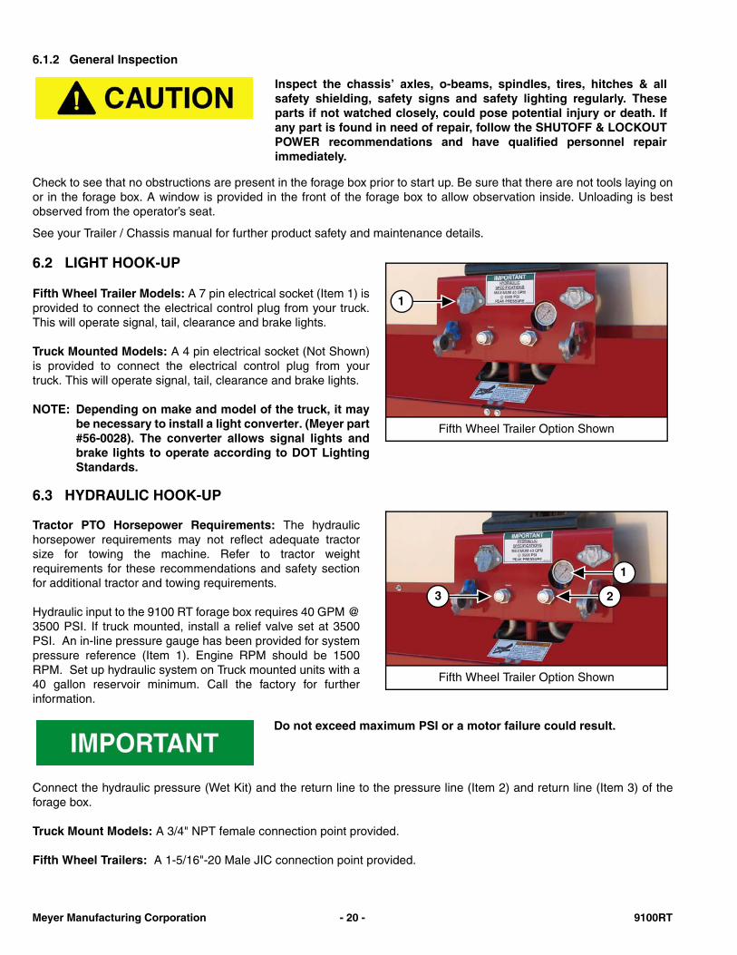
Fifth Wheel Trailer Models: A 7 pin electrical socket (Item 1) isprovided to connect the electrical control plug from your truck.This will operate signal, tail, clearance and brake lights.
Truck Mounted Models: A 4 pin electrical socket (Not Shown)is provided to connect the electrical control plug from yourtruck. This will operate signal, tail, clearance and brake lights.
NOTE: Depending on make and model of the truck, it maybe necessary to install a light converter. (Meyer part#56-0028). The converter allows signal lights andbrake lights to operate according to DOT LightingStandards.
6.3 HYDRAULIC HOOK-UP
Tractor PTO Horsepower Requirements: The hydraulichorsepower requirements may not reflect adequate tractorsize for towing the machine. Refer to tractor weightrequirements for these recommendations and safety sectionfor additional tractor and towing requirements.
Hydraulic input to the 9100 RT forage box requires 40 GPM @3500 PSI. If truck mounted, install a relief valve set at 3500PSI. An in-line pressure gauge has been provided for systempressure reference (Item 1). Engine RPM should be 1500RPM. Set up hydraulic system on Truck mounted units with a40 gallon reservoir minimum. Call the factory for furtherinformation.
Connect the hydraulic pressure (Wet Kit) and the return line to the pressure line (Item 2) and return line (Item 3) of theforage box.
Truck Mount Models: A 3/4" NPT female connection point provided.
Fifth Wheel Trailers: A 1-5/16"-20 Male JIC connection point provided.
Inspect the chassis’ axles, o-beams, spindles, tires, hitches & allsafety shielding, safety signs and safety lighting regularly. Theseparts if not watched closely, could pose potential injury or death. Ifany part is found in need of repair, follow the SHUTOFF & LOCKOUTPOWER recommendations and have qualified personnel repairimmediately.
Fifth Wheel Trailer Option Shown
1
Fifth Wheel Trailer Option Shown
1
3 2
Do not exceed maximum PSI or a motor failure could result.
Meyer Manufacturing Corporation - 20 - 9100RT
6.4 AIR BRAKE HOOK-UP (FIFTH WHEEL TRAILER MODELS)
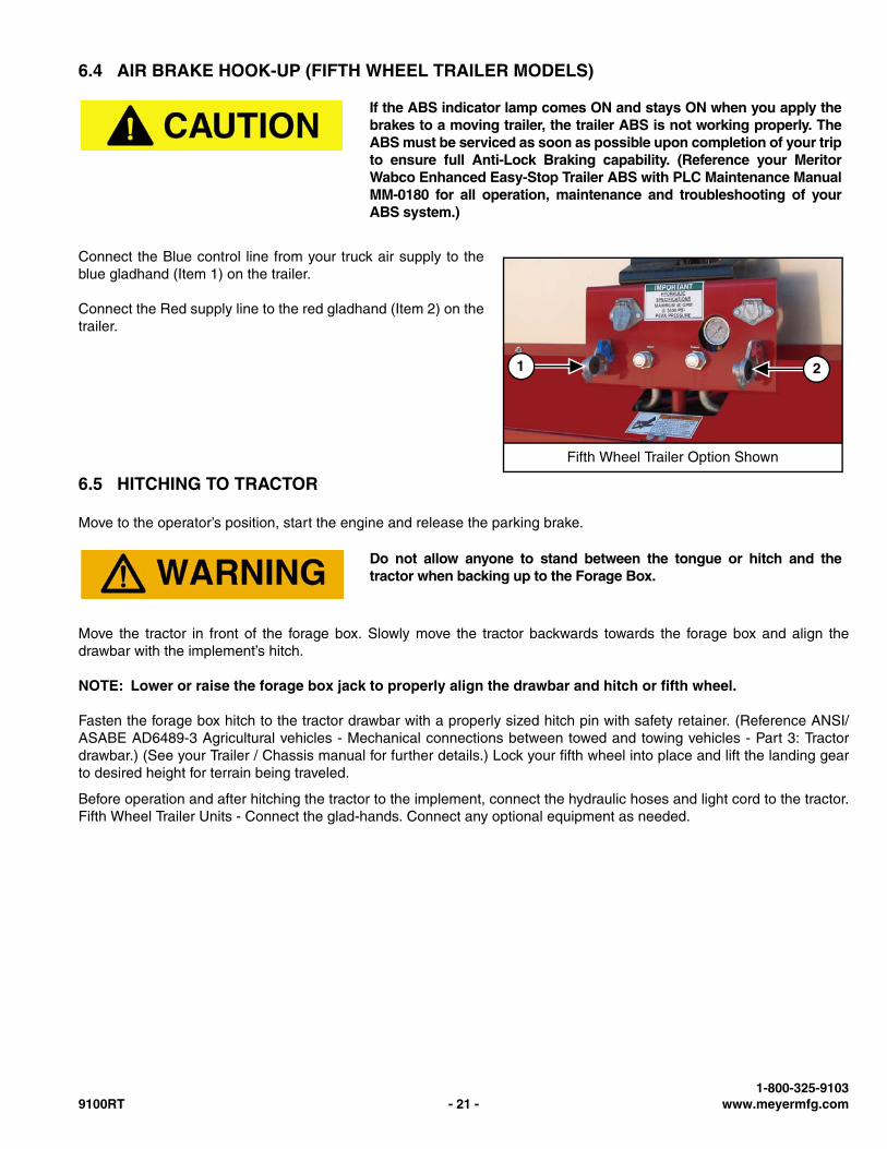
Connect the Blue control line from your truck air supply to theblue gladhand (Item 1) on the trailer.
Connect the Red supply line to the red gladhand (Item 2) on thetrailer.
6.5 HITCHING TO TRACTOR
Move to the operator’s position, start the engine and release the parking brake.
Move the tractor in front of the forage box. Slowly move the tractor backwards towards the forage box and align thedrawbar with the implement’s hitch.
NOTE: Lower or raise the forage box jack to properly align the drawbar and hitch or fifth wheel.
Fasten the forage box hitch to the tractor drawbar with a properly sized hitch pin with safety retainer. (Reference ANSI/ASABE AD6489-3 Agricultural vehicles - Mechanical connections between towed and towing vehicles - Part 3: Tractordrawbar.) (See your Trailer / Chassis manual for further details.) Lock your fifth wheel into place and lift the landing gearto desired height for terrain being traveled.
Before operation and after hitching the tractor to the implement, connect the hydraulic hoses and light cord to the tractor.Fifth Wheel Trailer Units - Connect the glad-hands. Connect any optional equipment as needed.
If the ABS indicator lamp comes ON and stays ON when you apply thebrakes to a moving trailer, the trailer ABS is not working properly. TheABS must be serviced as soon as possible upon completion of your tripto ensure full Anti-Lock Braking capability. (Reference your MeritorWabco Enhanced Easy-Stop Trailer ABS with PLC Maintenance ManualMM-0180 for all operation, maintenance and troubleshooting of yourABS system.)
Fifth Wheel Trailer Option Shown
1 2
Do not allow anyone to stand between the tongue or hitch and thetractor when backing up to the Forage Box.
1-800-325-91039100RT - 21 - www.meyermfg.com
6.6 START-UP AND SHUT-DOWN
6.6.1 Start-Up
Enter the tractor or truck and start the engine.
Slowly engage the PTO / hydraulics and operate at idle speed.
Have a second person visually inspect that the forage box is operating properly.
Disengage the PTO / hydraulics and stop the engine.
6.6.2 Shut-Down
Disengage the PTO / hydraulics.
Park the tractor / truck on a flat, level surface.
Engage the parking brake, stop the engine and exit the tractor or truck.
6.7 OPERATIONAL CHECKS
Before filling the forage box, slowly engage the hydraulics and operate at idle speed to ensure that the forage box isoperating properly.
Adjust and lubricate equipment as needed. (See 8.2 ADJUSTMENTS on page 33.) & (See 8.1 LUBRICATION onpage 31.)
DO NOT allow anyone to operate, service, inspect or otherwise handlethis forage box until all operators have read and understand all of theinstructional materials in this Operator’s And Parts Manual and havebeen properly trained in its intended usage.
Before operating the forage box, look in all directions and make sureno bystanders, especially small children are in the work area.
Disengage the hydraulic power, engage the machine’s parking brake,stop the engine and make sure all moving components arecompletely stopped before connecting, disconnecting, adjusting orcleaning this equipment.
Always keep all shields and guards in place and securely fastened.
Keep hands, feet and clothing away.
Before operating the forage box, look in all directions and make sureno bystanders, especially small children are in the work area.
Meyer Manufacturing Corporation - 22 - 9100RT
6.8 TRANSPORTING
AVOID SERIOUS INJURY OR DEATH
• Read and understand owner’s manual before using. Reviewsafety precautions annually.
• Before operating the forage box, look in all directions and makesure no bystanders, especially small children are in the workarea.
• No riders allowed when transporting.• Do not drink and drive.• Before moving, be sure required lights and reflectors are
installed and working.• Before maintenance or repair, stop vehicle, set parking brake,
and remove ignition key.• Place safety stands under frame and chock wheels before
working on tires or chassis.• Maintain wheel bolts at torque as recommended in the manual.• If equipped with brakes, maintain proper adjustment.
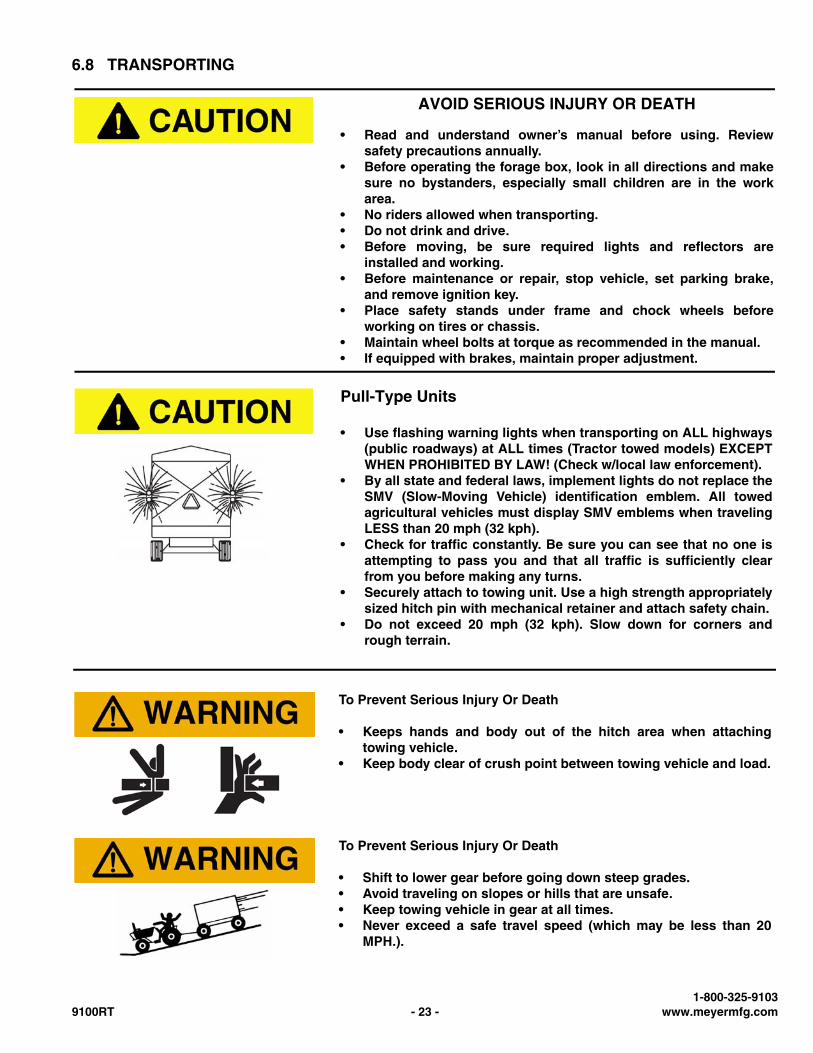
Pull-Type Units
• Use flashing warning lights when transporting on ALL highways(public roadways) at ALL times (Tractor towed models) EXCEPTWHEN PROHIBITED BY LAW! (Check w/local law enforcement).
• By all state and federal laws, implement lights do not replace theSMV (Slow-Moving Vehicle) identification emblem. All towedagricultural vehicles must display SMV emblems when travelingLESS than 20 mph (32 kph).
• Check for traffic constantly. Be sure you can see that no one isattempting to pass you and that all traffic is sufficiently clearfrom you before making any turns.
• Securely attach to towing unit. Use a high strength appropriatelysized hitch pin with mechanical retainer and attach safety chain.
• Do not exceed 20 mph (32 kph). Slow down for corners andrough terrain.
To Prevent Serious Injury Or Death
• Keeps hands and body out of the hitch area when attachingtowing vehicle.
• Keep body clear of crush point between towing vehicle and load.
To Prevent Serious Injury Or Death
• Shift to lower gear before going down steep grades.• Avoid traveling on slopes or hills that are unsafe.• Keep towing vehicle in gear at all times.• Never exceed a safe travel speed (which may be less than 20
MPH.).
1-800-325-91039100RT - 23 - www.meyermfg.com
NOTE: An Optional Highway Lighting Package is available to assist in meeting these requirements. See yourMeyer Dealer for Details.
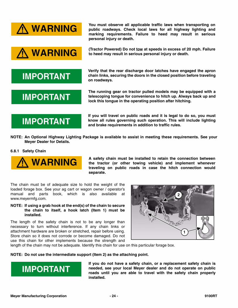
6.8.1 Safety Chain
The chain must be of adequate size to hold the weight of theloaded forage box. See your ag cart or wagon owner / operator’smanual and parts book, which is also available atwww.meyermfg.com.
NOTE: If using a grab hook at the end(s) of the chain to securethe chain to itself, a hook latch (Item 1) must beinstalled.
The length of the safety chain is not to be any longer thannecessary to turn without interference. If any chain links orattachment hardware are broken or stretched, repair before using.Store chain so it does not corrode or become damaged. Do notuse this chain for other implements because the strength andlength of the chain may not be adequate. Identify this chain for use on this particular forage box.
NOTE: Do not use the intermediate support (Item 2) as the attaching point.
You must observe all applicable traffic laws when transporting onpublic roadways. Check local laws for all highway lighting andmarking requirements. Failure to heed may result in seriouspersonal injury or death.
(Tractor Powered) Do not tow at speeds in excess of 20 mph. Failureto heed may result in serious personal injury or death.
Verify that the rear discharge door latches have engaged the apronchain links, securing the doors in the closed position before travelingon roadways.
The running gear on tractor pulled models may be equipped with atelescoping tongue for convenience to hitch up. Always back up andlock this tongue in the operating position after hitching.
If you will travel on public roads and it is legal to do so, you mustknow all rules governing such operation. This will include lightingand brake requirements in addition to traffic rules.
A safety chain must be installed to retain the connection betweenthe tractor (or other towing vehicle) and implement whenevertraveling on public roads in case the hitch connection wouldseparate.
1
2
If you do not have a safety chain, or a replacement safety chain isneeded, see your local Meyer dealer and do not operate on publicroads until you are able to travel with the safety chain properlyinstalled.
Meyer Manufacturing Corporation - 24 - 9100RT
6.8.2 Brake Information
See your trailer / chassis manual for brake and braking Information.
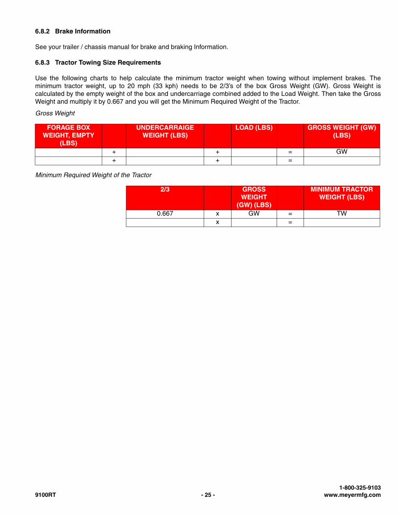
6.8.3 Tractor Towing Size Requirements
Use the following charts to help calculate the minimum tractor weight when towing without implement brakes. Theminimum tractor weight, up to 20 mph (33 kph) needs to be 2/3’s of the box Gross Weight (GW). Gross Weight iscalculated by the empty weight of the box and undercarriage combined added to the Load Weight. Then take the GrossWeight and multiply it by 0.667 and you will get the Minimum Required Weight of the Tractor.
Gross Weight
Minimum Required Weight of the Tractor
FORAGE BOX WEIGHT, EMPTY
(LBS)
UNDERCARRAIGEWEIGHT (LBS)
LOAD (LBS) GROSS WEIGHT (GW) (LBS)
+ + = GW+ + =
2/3 GROSS WEIGHT
(GW) (LBS)
MINIMUM TRACTOR WEIGHT (LBS)
0.667 x GW = TWx =
1-800-325-91039100RT - 25 - www.meyermfg.com
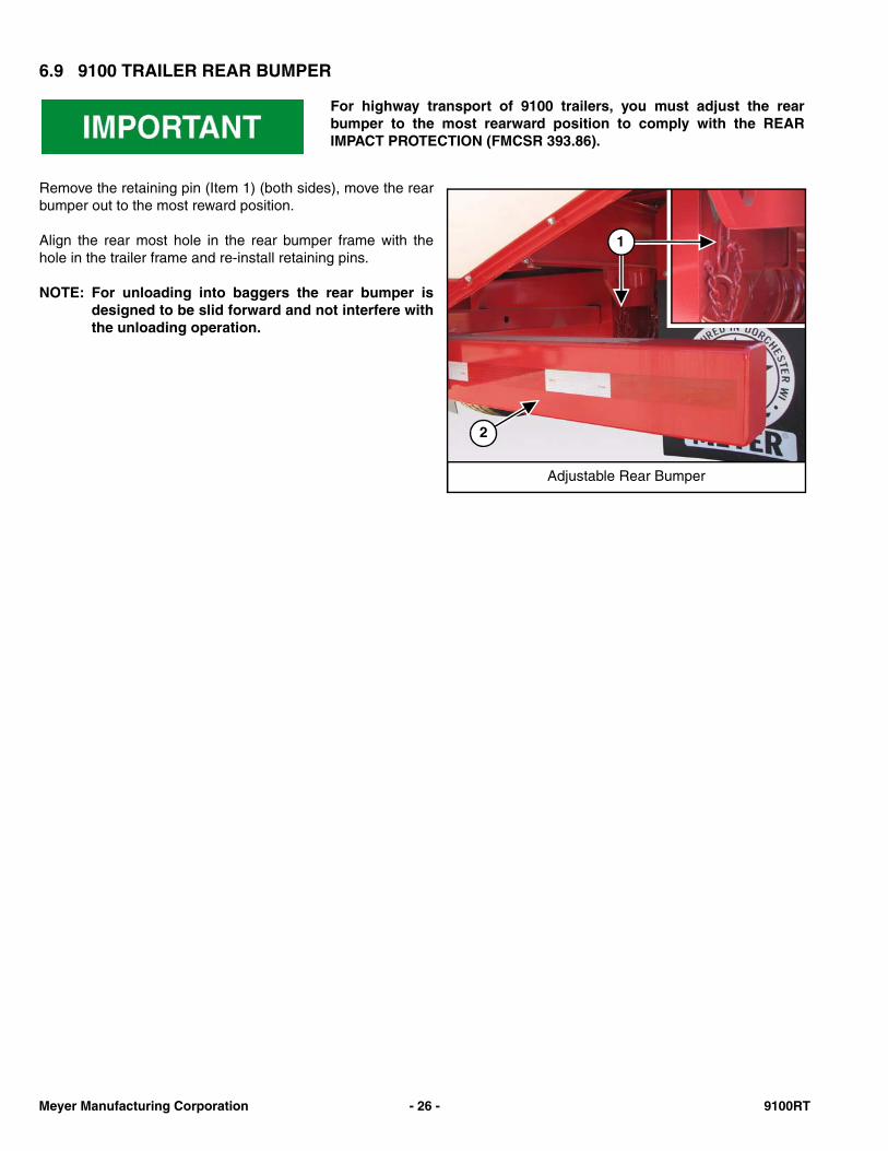
6.9 9100 TRAILER REAR BUMPER
Remove the retaining pin (Item 1) (both sides), move the rearbumper out to the most reward position.
Align the rear most hole in the rear bumper frame with thehole in the trailer frame and re-install retaining pins.
NOTE: For unloading into baggers the rear bumper isdesigned to be slid forward and not interfere withthe unloading operation.
For highway transport of 9100 trailers, you must adjust the rearbumper to the most rearward position to comply with the REARIMPACT PROTECTION (FMCSR 393.86).
Adjustable Rear Bumper
2
1
Meyer Manufacturing Corporation - 26 - 9100RT
7.0 OPERATION
7.1 LOADING
NOTE: Heaping material over the sides of the box will add a significant amount of weight to the load.
NOTE: Overloading can have detrimental effects on the integrity of the implement and it’s safe use. Somematerials such as soybeans may not be able to be filled to struck level. Overloading will void warranty andincrease risk to the operator's safety. Always be aware of your gross weight.
NOTE: Maximum Gross Weight is the lesser value between the Implement, chassis, or tires
NOTE: The front of the forage box is equipped with a plexiglass window(s) to monitor forage level from theoperator’s position.
Drive alongside the loading vehicle. Fill the forage box evenly to properly distribute the load while loading. Whendumping into the box with an end-loader, center the bucket just forward of the axle to properly distribute the load whileloading.
MAXIMUM FORAGE BOX GROSS WEIGHT MATERIAL ESTIMATED WEIGHTPER CUBIC FOOT
MODEL LBS MATERIAL LBS / CU.FT.9124RT 54,000 Soybeans 47 lbs.9126RT 54,000 Cotton Seed (Dry) 20 lbs.9128RT 54,000 Corn (Shelled) 45 lbs.9130RT 54,000 Corn Silage 30 lbs.
9130T - RT 60,000 Haylage 20 lbs.9136T - RT 60,000 Sawdust 17 lbs.9140T - RT 60,000 Source: SAE D384.2
DO NOT allow anyone to operate, service, inspect or otherwisehandle this forage box until all operators have read and understandall of the instructional materials in this Operator’s And Parts Manualand have been properly trained in its intended usage.
Before operating the forage box, look in all directions and make sureno bystanders, especially small children are in the work area.
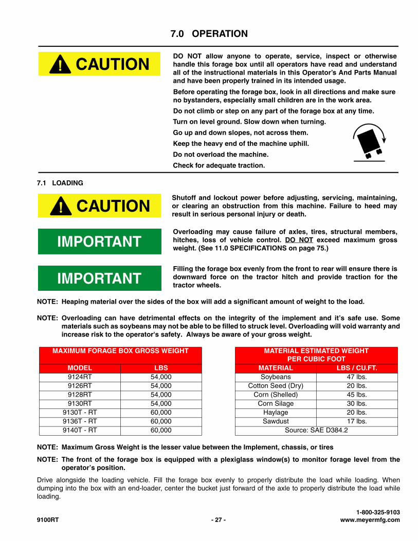
Do not climb or step on any part of the forage box at any time.
Turn on level ground. Slow down when turning.
Go up and down slopes, not across them.
Keep the heavy end of the machine uphill.
Do not overload the machine.
Check for adequate traction.
Shutoff and lockout power before adjusting, servicing, maintaining,or clearing an obstruction from this machine. Failure to heed mayresult in serious personal injury or death.
Overloading may cause failure of axles, tires, structural members,hitches, loss of vehicle control. DO NOT exceed maximum grossweight. (See 11.0 SPECIFICATIONS on page 75.)
Filling the forage box evenly from the front to rear will ensure there isdownward force on the tractor hitch and provide traction for thetractor wheels.
1-800-325-91039100RT - 27 - www.meyermfg.com
7.2 UNLOADING
NOTE: Unloading is best observed from the operator’s seat.
NOTE: The front of the forage box is equipped with plexiglass windows to monitor forage level from theoperator’s seat.
Enter the tractor / truck, start the engine, release the parking brake.
Move the tractor / truck and forage box to the unloading area.
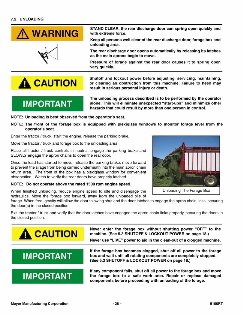
Place all tractor / truck controls in neutral, engage the parking brake andSLOWLY engage the apron chains to open the rear door.
Once the load has started to move, release the parking brake, move forwardto prevent the silage from being carried underneath into the main apron chainreturn area. The front of the box has a plexiglass window for convenientobservation. Watch to verify the rear doors have properly latched.
NOTE: Do not operate above the rated 1500 rpm engine speed.
When finished unloading, reduce engine speed to idle and disengage thehydraulics. Move the forage box forward, away from the unloaded pile offorage. When free, gravity will allow the door to swing shut and the door latches to engage the apron chain links, securingthe door(s) in the closed position.
Exit the tractor / truck and verify that the door latches have engaged the apron chain links properly, securing the doors inthe closed position.
STAND CLEAR, the rear discharge door can spring open quickly andwith extreme force.
Keep all persons well clear of the rear discharge door, forage box andunloading area.
The rear discharge door opens automatically by releasing its latchesas the main aprons begin to move.
Pressure of forage against the rear door causes it to spring openvery quickly.
Shutoff and lockout power before adjusting, servicing, maintaining,or clearing an obstruction from this machine. Failure to heed mayresult in serious personal injury or death.
The unloading process described is to be performed by the operatoralone. This will eliminate unexpected “start-ups” and minimize otherhazards that could result by more than one person in control.
Unloading The Forage Box
Never enter the forage box without shutting power “OFF” to themachine. (See 5.3 SHUTOFF & LOCKOUT POWER on page 18.)
Never use “LIVE” power to aid in the clean-out of a clogged machine.
If the forage box becomes clogged, shut off all power to the foragebox and wait until all rotating components are completely stopped. (See 5.3 SHUTOFF & LOCKOUT POWER on page 18.)
If any component fails, shut off all power to the forage box and movethe forage box to a safe work area. Repair or replace damagedcomponents before proceeding with unloading of the forage.
Meyer Manufacturing Corporation - 28 - 9100RT
Unloading Into A Bunker
Keep moving forward to prevent forage from being carried underneath into the main apron chain return area.
7.3 UNHOOKING THE TRACTOR
1. Park the implement on level ground. Put the tractor controls in neutral, set the parking brake, and turn the engine offbefore dismounting.
2. Place wheel chocks in front and in back of the implement wheels on opposite sides to prevent the implement fromrolling after the tractor is unhooked.
3. Remove the hydraulic hose ends from the tractor hydraulic ports and secure the hose ends on the front of the box tokeep them clean.
4. Remove the light cords and any optional equipment connections. Fifth Wheel Trailer Models - Disconnect the glad-hands.
5. Pull Type Models - Remove the jack from the storage mount and install it on the hitch tongue. Crank the jack downuntil the hitch lifts off the tractor draw bar.
6. Pull Type Models - Remove the hitch pin.
7. Pull Type Models - Unhook safety chain from tractor drawbar and intermediate support.
8. Pull Type Models - Slowly drive the tractor away from the implement.
9. Fifth Wheel Trailer Models - Lower the landing gear, unlock the fifth wheel, and pull out from under the trailer.
7.4 STANDARD REAR DISCHARGE DOOR AND GATE DELAY
How The Door Opens
Your gate delay is plumbed into your hydraulic line. When you turnon your hydraulic PTO, it pressurizes your rear gate cylinder. Thedoor releases from the apron chain and the forage pushes the gateopen. When the forage is nearing the end of cleaning out, you willsee the gate held open by the hydraulic cylinder.
How The Door Closes
When finished unloading, reduce engine speed to idle anddisengage hydraulic power.
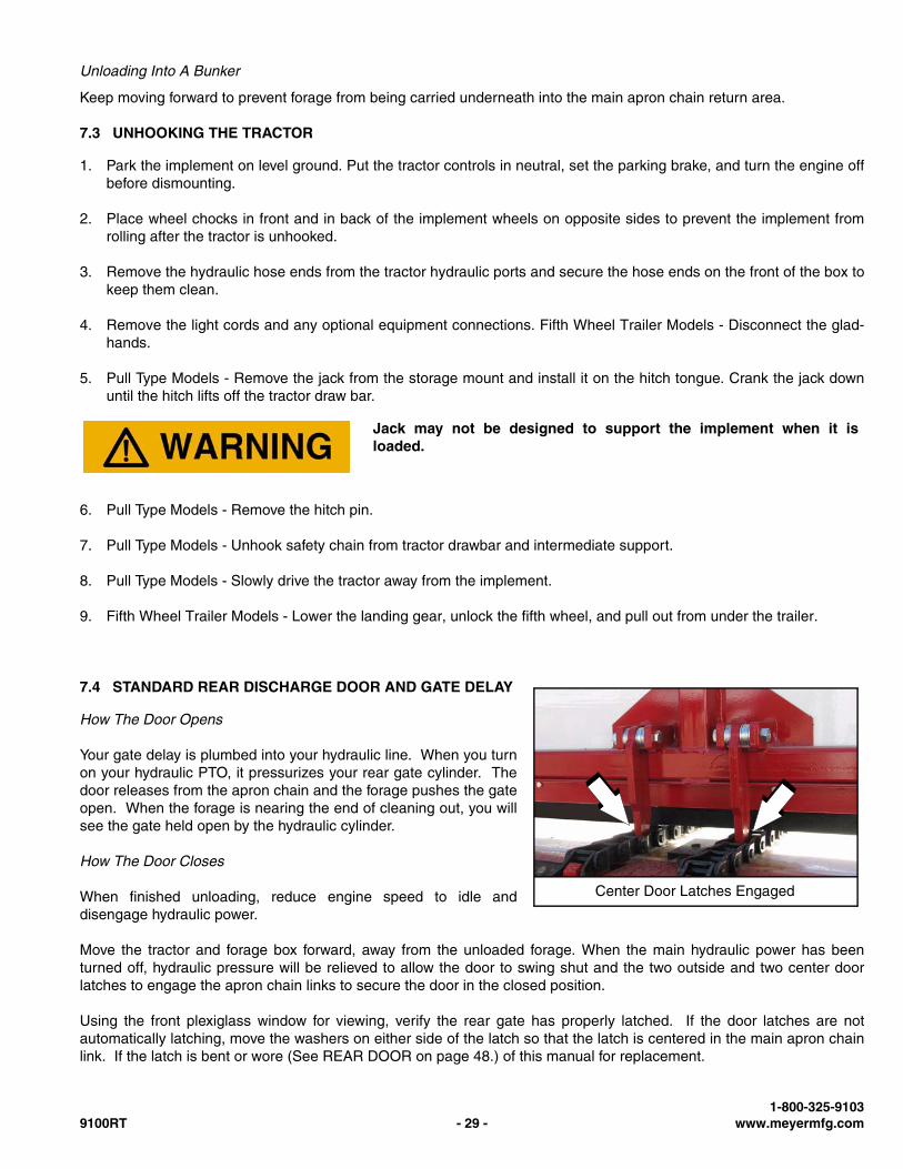
Move the tractor and forage box forward, away from the unloaded forage. When the main hydraulic power has beenturned off, hydraulic pressure will be relieved to allow the door to swing shut and the two outside and two center doorlatches to engage the apron chain links to secure the door in the closed position.
Using the front plexiglass window for viewing, verify the rear gate has properly latched. If the door latches are notautomatically latching, move the washers on either side of the latch so that the latch is centered in the main apron chainlink. If the latch is bent or wore (See REAR DOOR on page 48.) of this manual for replacement.
Jack may not be designed to support the implement when it isloaded.
Center Door Latches Engaged
1-800-325-91039100RT - 29 - www.meyermfg.com
7.5 AIR DOUBLE DOOR (OPTIONAL)
Opening The Doors
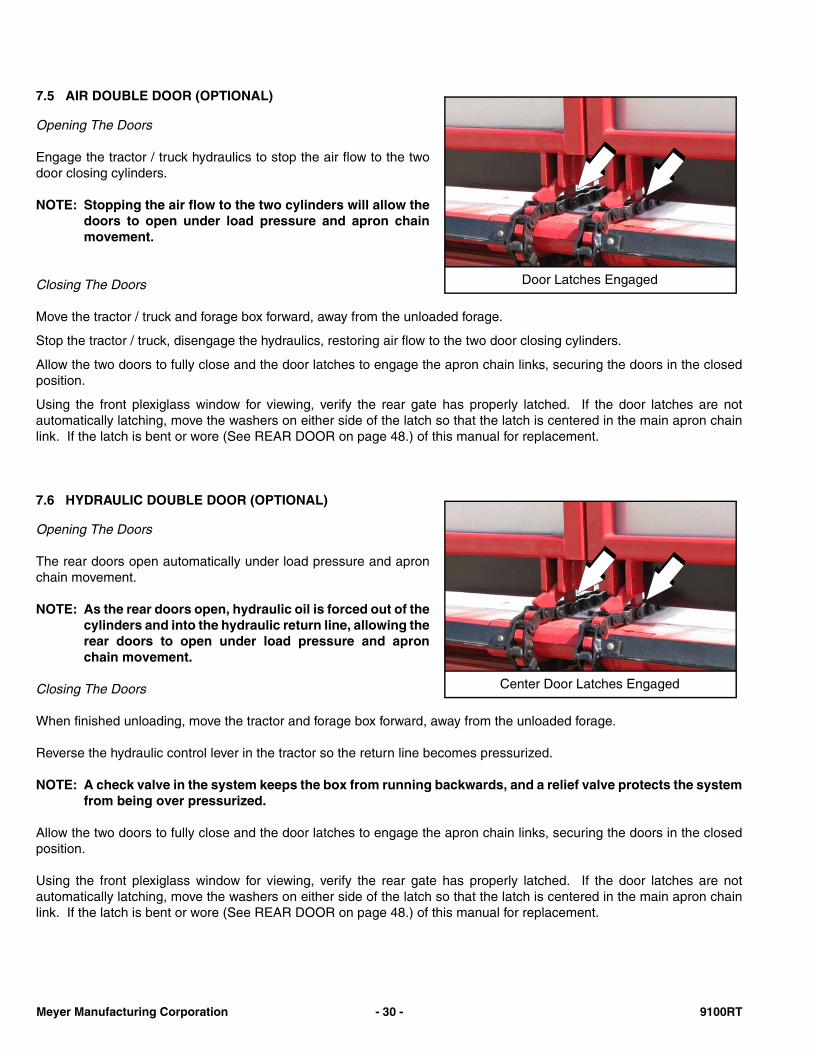
Engage the tractor / truck hydraulics to stop the air flow to the twodoor closing cylinders.
NOTE: Stopping the air flow to the two cylinders will allow thedoors to open under load pressure and apron chainmovement.
Closing The Doors
Move the tractor / truck and forage box forward, away from the unloaded forage.
Stop the tractor / truck, disengage the hydraulics, restoring air flow to the two door closing cylinders.
Allow the two doors to fully close and the door latches to engage the apron chain links, securing the doors in the closedposition.
Using the front plexiglass window for viewing, verify the rear gate has properly latched. If the door latches are notautomatically latching, move the washers on either side of the latch so that the latch is centered in the main apron chainlink. If the latch is bent or wore (See REAR DOOR on page 48.) of this manual for replacement.
7.6 HYDRAULIC DOUBLE DOOR (OPTIONAL)
Opening The Doors
The rear doors open automatically under load pressure and apronchain movement.
NOTE: As the rear doors open, hydraulic oil is forced out of thecylinders and into the hydraulic return line, allowing therear doors to open under load pressure and apronchain movement.
Closing The Doors
When finished unloading, move the tractor and forage box forward, away from the unloaded forage.
Reverse the hydraulic control lever in the tractor so the return line becomes pressurized.
NOTE: A check valve in the system keeps the box from running backwards, and a relief valve protects the systemfrom being over pressurized.
Allow the two doors to fully close and the door latches to engage the apron chain links, securing the doors in the closedposition.
Using the front plexiglass window for viewing, verify the rear gate has properly latched. If the door latches are notautomatically latching, move the washers on either side of the latch so that the latch is centered in the main apron chainlink. If the latch is bent or wore (See REAR DOOR on page 48.) of this manual for replacement.
Door Latches Engaged
Center Door Latches Engaged
Meyer Manufacturing Corporation - 30 - 9100RT
8.0 MAINTENANCE
8.1 LUBRICATION
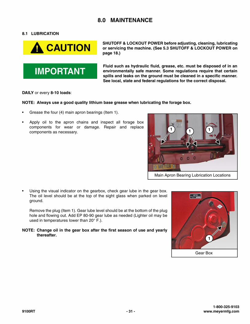
DAILY or every 8-10 loads:
NOTE: Always use a good quality lithium base grease when lubricating the forage box.
• Grease the four (4) main apron bearings (Item 1).
• Apply oil to the apron chains and inspect all forage boxcomponents for wear or damage. Repair and replacecomponents as necessary.
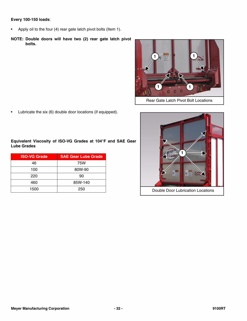
• Using the visual indicator on the gearbox, check gear lube in the gear box.The oil level should be at the top of the sight glass when parked on levelground.
Remove the plug (Item 1). Gear lube level should be at the bottom of the plughole and flowing out. Add EP 80-90 gear lube as needed (Lighter oil may beused in temperatures lower than 20° F.).
NOTE: Change oil in the gear box after the first season of use and yearlythereafter.
SHUTOFF & LOCKOUT POWER before adjusting, cleaning, lubricatingor servicing the machine. (See 5.3 SHUTOFF & LOCKOUT POWER onpage 18.)
Fluid such as hydraulic fluid, grease, etc. must be disposed of in anenvironmentally safe manner. Some regulations require that certainspills and leaks on the ground must be cleaned in a specific manner.See local, state and federal regulations for the correct disposal.
Main Apron Bearing Lubrication Locations
11 1
Gear Box
1
1-800-325-91039100RT - 31 - www.meyermfg.com
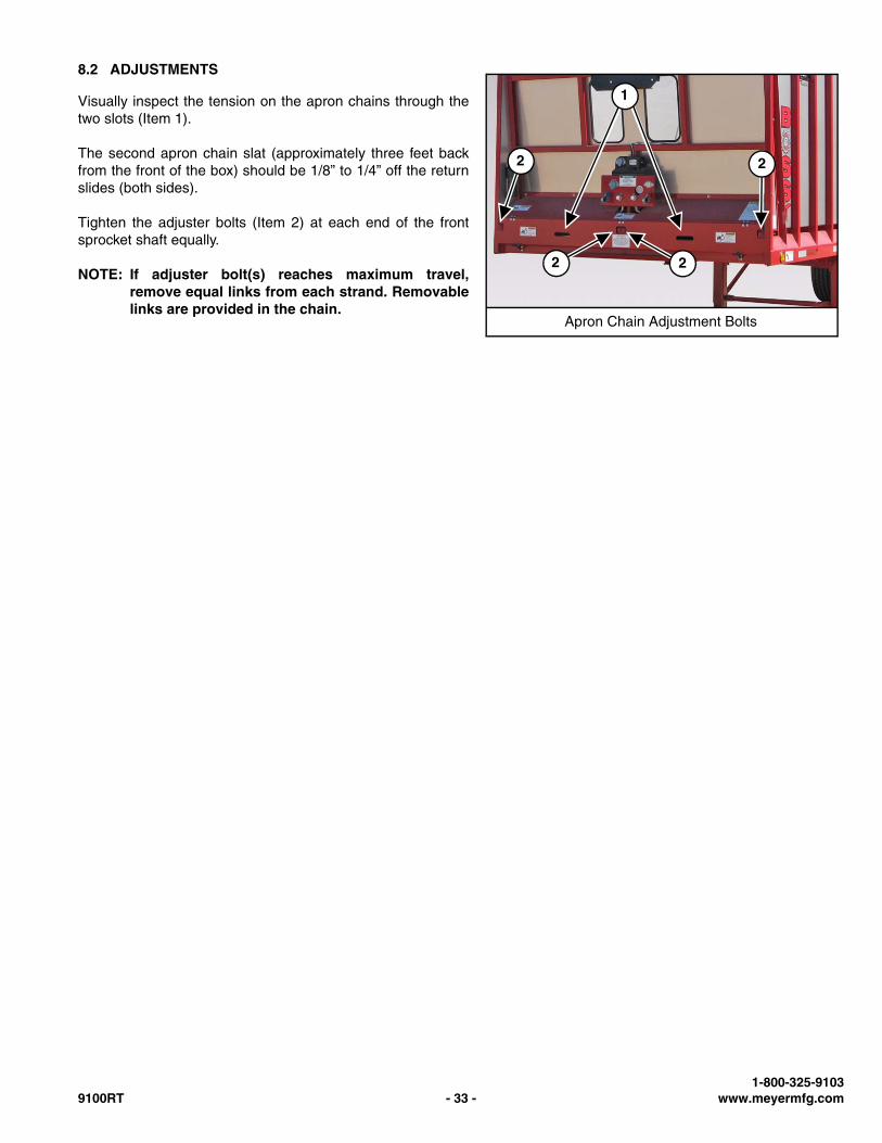
Every 100-150 loads:
• Apply oil to the four (4) rear gate latch pivot bolts (Item 1).
NOTE: Double doors will have two (2) rear gate latch pivotbolts.
• Lubricate the six (6) double door locations (if equipped).
Equivalent Viscosity of ISO-VG Grades at 104°F and SAE GearLube Grades
ISO-VG Grade SAE Gear Lube Grade
46 75W
100 80W-90
220 90
460 85W-140
1500 250
Rear Gate Latch Pivot Bolt Locations
1 1
1 1
Double Door Lubrication Locations
1
Meyer Manufacturing Corporation - 32 - 9100RT
8.2 ADJUSTMENTS
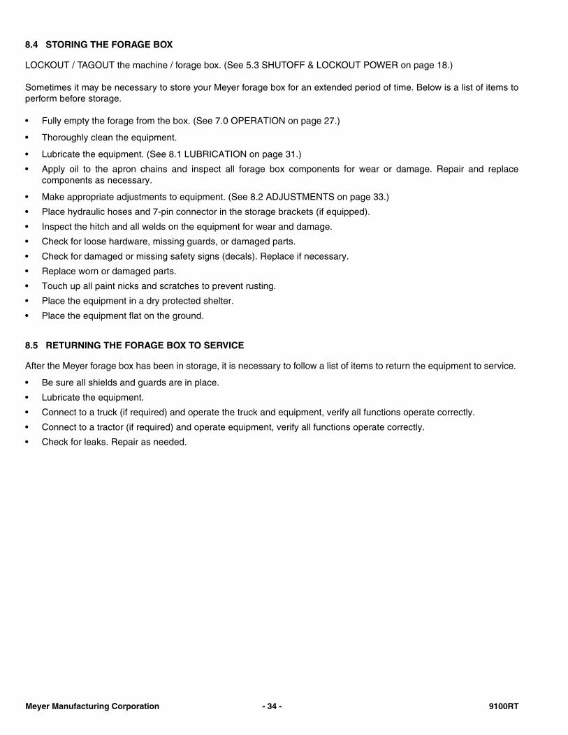
Visually inspect the tension on the apron chains through thetwo slots (Item 1).
The second apron chain slat (approximately three feet backfrom the front of the box) should be 1/8” to 1/4” off the returnslides (both sides).
Tighten the adjuster bolts (Item 2) at each end of the frontsprocket shaft equally.
NOTE: If adjuster bolt(s) reaches maximum travel,remove equal links from each strand. Removablelinks are provided in the chain.
Apron Chain Adjustment Bolts
1
22
2 2
1-800-325-91039100RT - 33 - www.meyermfg.com
8.4 STORING THE FORAGE BOX
LOCKOUT / TAGOUT the machine / forage box. (See 5.3 SHUTOFF & LOCKOUT POWER on page 18.)
Sometimes it may be necessary to store your Meyer forage box for an extended period of time. Below is a list of items toperform before storage.
• Fully empty the forage from the box. (See 7.0 OPERATION on page 27.)
• Thoroughly clean the equipment.
• Lubricate the equipment. (See 8.1 LUBRICATION on page 31.)
• Apply oil to the apron chains and inspect all forage box components for wear or damage. Repair and replacecomponents as necessary.
• Make appropriate adjustments to equipment. (See 8.2 ADJUSTMENTS on page 33.)
• Place hydraulic hoses and 7-pin connector in the storage brackets (if equipped).
• Inspect the hitch and all welds on the equipment for wear and damage.
• Check for loose hardware, missing guards, or damaged parts.
• Check for damaged or missing safety signs (decals). Replace if necessary.
• Replace worn or damaged parts.
• Touch up all paint nicks and scratches to prevent rusting.
• Place the equipment in a dry protected shelter.
• Place the equipment flat on the ground.
8.5 RETURNING THE FORAGE BOX TO SERVICE
After the Meyer forage box has been in storage, it is necessary to follow a list of items to return the equipment to service.
• Be sure all shields and guards are in place.
• Lubricate the equipment.
• Connect to a truck (if required) and operate the truck and equipment, verify all functions operate correctly.
• Connect to a tractor (if required) and operate equipment, verify all functions operate correctly.
• Check for leaks. Repair as needed.
Meyer Manufacturing Corporation - 34 - 9100RT
9.0 PARTS REPAIR AND REPLACEMENT
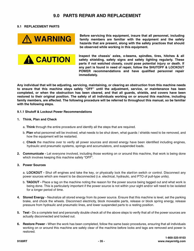
9.1 REPLACEMENT PARTS
Any individual that will be adjusting, servicing, maintaining, or clearing an obstruction from this machine needsto ensure that this machine stays safely “OFF” until the adjustment, service, or maintenance has beencompleted, or when the obstruction has been cleared, and that all guards, shields, and covers have beenrestored to their original position. The safety of all individuals working on or around this machine, includingfamily members, are affected. The following procedure will be referred to throughout this manual, so be familiarwith the following steps.
9.1.1 Shutoff & Lockout Power Recommendations
1. Think, Plan and Check
a. Think through the entire procedure and identify all the steps that are required.
b. Plan what personnel will be involved, what needs to be shut down, what guards / shields need to be removed, andhow the equipment will be restarted.
c. Check the machine over to verify all power sources and stored energy have been identified including engines,hydraulic and pneumatic systems, springs and accumulators, and suspended loads.
2. Communicate - Let everyone involved, including those working on or around this machine, that work is being donewhich involves keeping this machine safely “OFF”.
3. Power Sources
a. LOCKOUT - Shut off engines and take the key, or physically lock the start/on switch or control. Disconnect anypower sources which are meant to be disconnected (i.e. electrical, hydraulic, and PTO of pull-type units).
b. TAGOUT - Place a tag on the machine noting the reason for the power source being tagged out and what work isbeing done. This is particularly important if the power source is not within your sight and/or will need to be isolatedfor a longer period of time.
4. Stored Energy - Neutralize all stored energy from its power source. Ensure that this machine is level, set the parkingbrake, and chock the wheels. Disconnect electricity, block moveable parts, release or block spring energy, releasepressure from hydraulic and pneumatic lines, and lower suspended parts to a resting position.
5. Test - Do a complete test and personally double check all of the above steps to verify that all of the power sources areactually disconnected and locked out.
6. Restore Power - When the work has been completed, follow the same basic procedures, ensuring that all individualsworking on or around this machine are safely clear of the machine before locks and tags are removed and power isrestored.
Before servicing this equipment, insure that all personnel, includingfamily members are familiar with the equipment and the safetyhazards that are present, along with the safety practices that shouldbe observed while working in this equipment.
Inspect the chassis’ axles, o-beams, spindles, tires, hitches & allsafety shielding, safety signs and safety lighting regularly. Theseparts if not watched closely, could pose potential injury or death. Ifany part is found in need of repair, follow the SHUTOFF & LOCKOUTPOWER recommendations and have qualified personnel repairimmediately.
1-800-325-91039100RT - 35 - www.meyermfg.com
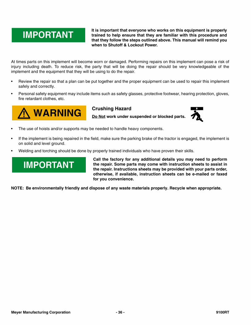
At times parts on this implement will become worn or damaged. Performing repairs on this implement can pose a risk ofinjury including death. To reduce risk, the party that will be doing the repair should be very knowledgeable of theimplement and the equipment that they will be using to do the repair.
• Review the repair so that a plan can be put together and the proper equipment can be used to repair this implementsafely and correctly.
• Personal safety equipment may include items such as safety glasses, protective footwear, hearing protection, gloves,fire retardant clothes, etc.
• The use of hoists and/or supports may be needed to handle heavy components.
• If the implement is being repaired in the field, make sure the parking brake of the tractor is engaged, the implement ison solid and level ground.
• Welding and torching should be done by properly trained individuals who have proven their skills.
NOTE: Be environmentally friendly and dispose of any waste materials properly. Recycle when appropriate.
It is important that everyone who works on this equipment is properlytrained to help ensure that they are familiar with this procedure andthat they follow the steps outlined above. This manual will remind youwhen to Shutoff & Lockout Power.
Crushing Hazard
Do Not work under suspended or blocked parts.
Call the factory for any additional details you may need to performthe repair. Some parts may come with instruction sheets to assist inthe repair. Instructions sheets may be provided with your parts order,otherwise, if available, instruction sheets can be e-mailed or faxedfor you convenience.
Meyer Manufacturing Corporation - 36 - 9100RT
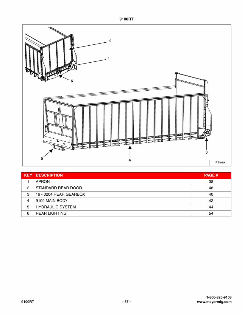
9100RT
KEY DESCRIPTION PAGE #
1 APRON 38
2 STANDARD REAR DOOR 48
3 19 - 0204 REAR GEARBOX 40
4 9100 MAIN BODY 42
5 HYDRAULIC SYSTEM 44
6 REAR LIGHTING 54
RT-019
1
2
3
45
6
1-800-325-91039100RT - 37 - www.meyermfg.com
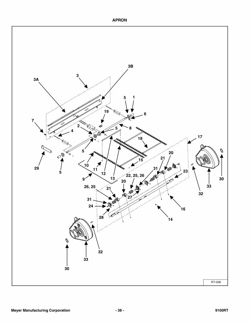
APRON
RT-038
1
33A
3B
7
4
196
8
529
2
1011
12139
15
18
24
31
17
26, 25
22, 25, 2620
28
27
31
14
16
23
30
30
32
32
5
5
5
3321
33
2120
Meyer Manufacturing Corporation - 38 - 9100RT
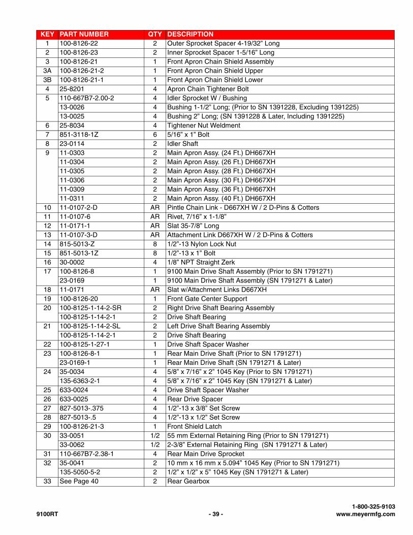
KEY PART NUMBER QTY DESCRIPTION1 100-8126-22 2 Outer Sprocket Spacer 4-19/32” Long2 100-8126-23 2 Inner Sprocket Spacer 1-5/16” Long3 100-8126-21 1 Front Apron Chain Shield Assembly
3A 100-8126-21-2 1 Front Apron Chain Shield Upper3B 100-8126-21-1 1 Front Apron Chain Shield Lower4 25-8201 4 Apron Chain Tightener Bolt5 110-667B7-2.00-2 4 Idler Sprocket W / Bushing
13-0026 4 Bushing 1-1/2” Long; (Prior to SN 1391228, Excluding 1391225)13-0025 4 Bushing 2” Long; (SN 1391228 & Later, Including 1391225)
6 25-8034 4 Tightener Nut Weldment7 851-3118-1Z 6 5/16” x 1” Bolt8 23-0114 2 Idler Shaft9 11-0303 2 Main Apron Assy. (24 Ft.) DH667XH
11-0304 2 Main Apron Assy. (26 Ft.) DH667XH11-0305 2 Main Apron Assy. (28 Ft.) DH667XH11-0306 2 Main Apron Assy. (30 Ft.) DH667XH11-0309 2 Main Apron Assy. (36 Ft.) DH667XH11-0311 2 Main Apron Assy. (40 Ft.) DH667XH
10 11-0107-2-D AR Pintle Chain Link - D667XH W / 2 D-Pins & Cotters11 11-0107-6 AR Rivet, 7/16” x 1-1/8”12 11-0171-1 AR Slat 35-7/8” Long13 11-0107-3-D AR Attachment Link D667XH W / 2 D-Pins & Cotters14 815-5013-Z 8 1/2”-13 Nylon Lock Nut15 851-5013-1Z 8 1/2”-13 x 1” Bolt16 30-0002 4 1/8” NPT Straight Zerk17 100-8126-8 1 9100 Main Drive Shaft Assembly (Prior to SN 1791271)
23-0169 1 9100 Main Drive Shaft Assembly (SN 1791271 & Later)18 11-0171 AR Slat w/Attachment Links D667XH19 100-8126-20 1 Front Gate Center Support20 100-8125-1-14-2-SR 2 Right Drive Shaft Bearing Assembly
100-8125-1-14-2-1 2 Drive Shaft Bearing21 100-8125-1-14-2-SL 2 Left Drive Shaft Bearing Assembly
100-8125-1-14-2-1 2 Drive Shaft Bearing22 100-8125-1-27-1 1 Drive Shaft Spacer Washer23 100-8126-8-1 1 Rear Main Drive Shaft (Prior to SN 1791271)
23-0169-1 1 Rear Main Drive Shaft (SN 1791271 & Later)24 35-0034 4 5/8” x 7/16” x 2” 1045 Key (Prior to SN 1791271)
135-6363-2-1 4 5/8” x 7/16” x 2” 1045 Key (SN 1791271 & Later)25 633-0024 4 Drive Shaft Spacer Washer26 633-0025 4 Rear Drive Spacer27 827-5013-.375 4 1/2”-13 x 3/8” Set Screw28 827-5013-.5 4 1/2”-13 x 1/2” Set Screw29 100-8126-21-3 1 Front Shield Latch30 33-0051 1/2 55 mm External Retaining Ring (Prior to SN 1791271)
33-0062 1/2 2-3/8” External Retaining Ring (SN 1791271 & Later)31 110-667B7-2.38-1 4 Rear Main Drive Sprocket32 35-0041 2 10 mm x 16 mm x 5.094” 1045 Key (Prior to SN 1791271)
135-5050-5-2 2 1/2” x 1/2” x 5” 1045 Key (SN 1791271 & Later)33 See Page 40 2 Rear Gearbox
1-800-325-91039100RT - 39 - www.meyermfg.com
REAR GEARBOX
RT-001
65
2 4
13
3
56
13
1411
8
97
17 16 15
18
191
1011
14
221222
111420
10
21
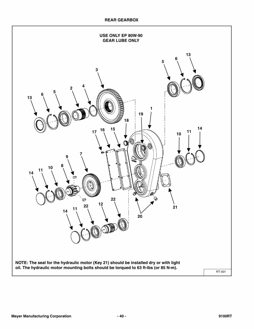
USE ONLY EP 80W-90 GEAR LUBE ONLY
NOTE: The seal for the hydraulic motor (Key 21) should be installed dry or with lightoil. The hydraulic motor mounting bolts should be torqued to 63 ft-lbs (or 85 N-m).
Meyer Manufacturing Corporation - 40 - 9100RT
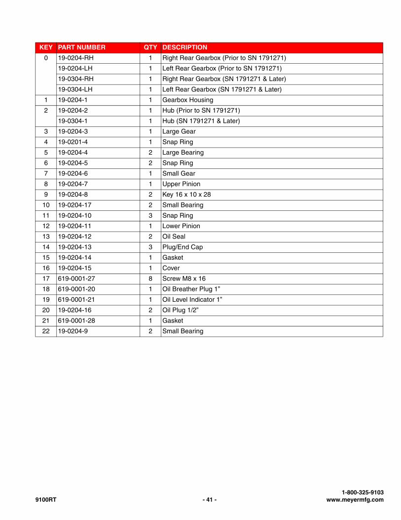
KEY PART NUMBER QTY DESCRIPTION
0 19-0204-RH 1 Right Rear Gearbox (Prior to SN 1791271)
19-0204-LH 1 Left Rear Gearbox (Prior to SN 1791271)
19-0304-RH 1 Right Rear Gearbox (SN 1791271 & Later)
19-0304-LH 1 Left Rear Gearbox (SN 1791271 & Later)
1 19-0204-1 1 Gearbox Housing
2 19-0204-2 1 Hub (Prior to SN 1791271)
19-0304-1 1 Hub (SN 1791271 & Later)
3 19-0204-3 1 Large Gear
4 19-0201-4 1 Snap Ring
5 19-0204-4 2 Large Bearing
6 19-0204-5 2 Snap Ring
7 19-0204-6 1 Small Gear
8 19-0204-7 1 Upper Pinion
9 19-0204-8 2 Key 16 x 10 x 28
10 19-0204-17 2 Small Bearing
11 19-0204-10 3 Snap Ring
12 19-0204-11 1 Lower Pinion
13 19-0204-12 2 Oil Seal
14 19-0204-13 3 Plug/End Cap
15 19-0204-14 1 Gasket
16 19-0204-15 1 Cover
17 619-0001-27 8 Screw M8 x 16
18 619-0001-20 1 Oil Breather Plug 1”
19 619-0001-21 1 Oil Level Indicator 1”
20 19-0204-16 2 Oil Plug 1/2”
21 619-0001-28 1 Gasket
22 19-0204-9 2 Small Bearing
1-800-325-91039100RT - 41 - www.meyermfg.com
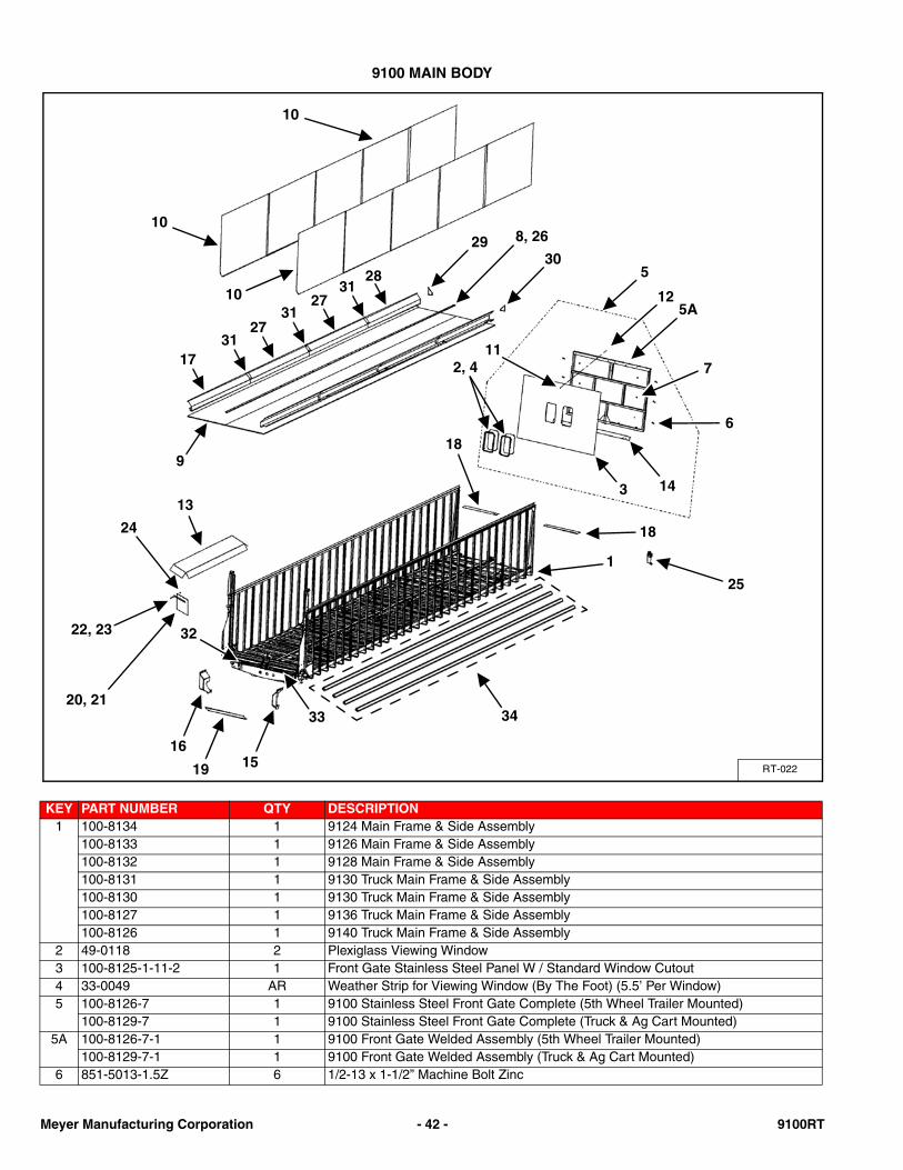
9100 MAIN BODY
KEY PART NUMBER QTY DESCRIPTION1 100-8134 1 9124 Main Frame & Side Assembly
100-8133 1 9126 Main Frame & Side Assembly100-8132 1 9128 Main Frame & Side Assembly100-8131 1 9130 Truck Main Frame & Side Assembly100-8130 1 9130 Truck Main Frame & Side Assembly100-8127 1 9136 Truck Main Frame & Side Assembly100-8126 1 9140 Truck Main Frame & Side Assembly
2 49-0118 2 Plexiglass Viewing Window3 100-8125-1-11-2 1 Front Gate Stainless Steel Panel W / Standard Window Cutout4 33-0049 AR Weather Strip for Viewing Window (By The Foot) (5.5’ Per Window)5 100-8126-7 1 9100 Stainless Steel Front Gate Complete (5th Wheel Trailer Mounted)
100-8129-7 1 9100 Stainless Steel Front Gate Complete (Truck & Ag Cart Mounted)5A 100-8126-7-1 1 9100 Front Gate Welded Assembly (5th Wheel Trailer Mounted)
100-8129-7-1 1 9100 Front Gate Welded Assembly (Truck & Ag Cart Mounted)6 851-5013-1.5Z 6 1/2-13 x 1-1/2” Machine Bolt Zinc
RT-022
1
10
10
10
29 8, 26
3028
3127
31
3127
17
9
13
18
2, 4
3 14
11
5
125A
6
7
18
25
22, 23
24
20, 21
19 1516
33
32
34
Meyer Manufacturing Corporation - 42 - 9100RT
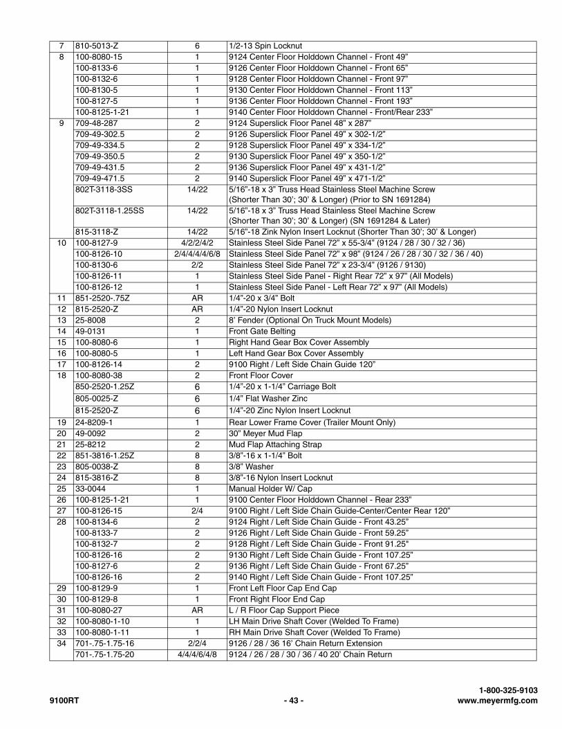
7 810-5013-Z 6 1/2-13 Spin Locknut8 100-8080-15 1 9124 Center Floor Holddown Channel - Front 49”
100-8133-6 1 9126 Center Floor Holddown Channel - Front 65”100-8132-6 1 9128 Center Floor Holddown Channel - Front 97”100-8130-5 1 9130 Center Floor Holddown Channel - Front 113”100-8127-5 1 9136 Center Floor Holddown Channel - Front 193”100-8125-1-21 1 9140 Center Floor Holddown Channel - Front/Rear 233”
9 709-48-287 2 9124 Superslick Floor Panel 48” x 287”709-49-302.5 2 9126 Superslick Floor Panel 49” x 302-1/2”709-49-334.5 2 9128 Superslick Floor Panel 49” x 334-1/2”709-49-350.5 2 9130 Superslick Floor Panel 49” x 350-1/2”709-49-431.5 2 9136 Superslick Floor Panel 49” x 431-1/2”709-49-471.5 2 9140 Superslick Floor Panel 49” x 471-1/2”802T-3118-3SS 14/22 5/16”-18 x 3” Truss Head Stainless Steel Machine Screw
(Shorter Than 30’; 30’ & Longer) (Prior to SN 1691284)802T-3118-1.25SS 14/22 5/16”-18 x 3” Truss Head Stainless Steel Machine Screw
(Shorter Than 30’; 30’ & Longer) (SN 1691284 & Later)815-3118-Z 14/22 5/16”-18 Zink Nylon Insert Locknut (Shorter Than 30’; 30’ & Longer)
10 100-8127-9 4/2/2/4/2 Stainless Steel Side Panel 72” x 55-3/4” (9124 / 28 / 30 / 32 / 36)100-8126-10 2/4/4/4/4/6/8 Stainless Steel Side Panel 72” x 98” (9124 / 26 / 28 / 30 / 32 / 36 / 40)100-8130-6 2/2 Stainless Steel Side Panel 72” x 23-3/4” (9126 / 9130)100-8126-11 1 Stainless Steel Side Panel - Right Rear 72” x 97” (All Models)100-8126-12 1 Stainless Steel Side Panel - Left Rear 72” x 97” (All Models)
11 851-2520-.75Z AR 1/4”-20 x 3/4” Bolt12 815-2520-Z AR 1/4”-20 Nylon Insert Locknut13 25-8008 2 8’ Fender (Optional On Truck Mount Models)14 49-0131 1 Front Gate Belting15 100-8080-6 1 Right Hand Gear Box Cover Assembly16 100-8080-5 1 Left Hand Gear Box Cover Assembly17 100-8126-14 2 9100 Right / Left Side Chain Guide 120”18 100-8080-38 2 Front Floor Cover
850-2520-1.25Z 6 1/4”-20 x 1-1/4” Carriage Bolt
805-0025-Z 6 1/4” Flat Washer Zinc815-2520-Z 6 1/4”-20 Zinc Nylon Insert Locknut
19 24-8209-1 1 Rear Lower Frame Cover (Trailer Mount Only)20 49-0092 2 30” Meyer Mud Flap21 25-8212 2 Mud Flap Attaching Strap22 851-3816-1.25Z 8 3/8”-16 x 1-1/4” Bolt23 805-0038-Z 8 3/8” Washer24 815-3816-Z 8 3/8”-16 Nylon Insert Locknut25 33-0044 1 Manual Holder W/ Cap26 100-8125-1-21 1 9100 Center Floor Holddown Channel - Rear 233”27 100-8126-15 2/4 9100 Right / Left Side Chain Guide-Center/Center Rear 120”28 100-8134-6 2 9124 Right / Left Side Chain Guide - Front 43.25”
100-8133-7 2 9126 Right / Left Side Chain Guide - Front 59.25”100-8132-7 2 9128 Right / Left Side Chain Guide - Front 91.25"100-8126-16 2 9130 Right / Left Side Chain Guide - Front 107.25”100-8127-6 2 9136 Right / Left Side Chain Guide - Front 67.25”100-8126-16 2 9140 Right / Left Side Chain Guide - Front 107.25”
29 100-8129-9 1 Front Left Floor Cap End Cap30 100-8129-8 1 Front Right Floor End Cap31 100-8080-27 AR L / R Floor Cap Support Piece32 100-8080-1-10 1 LH Main Drive Shaft Cover (Welded To Frame)33 100-8080-1-11 1 RH Main Drive Shaft Cover (Welded To Frame)34 701-.75-1.75-16 2/2/4 9126 / 28 / 36 16’ Chain Return Extension
701-.75-1.75-20 4/4/4/6/4/8 9124 / 26 / 28 / 30 / 36 / 40 20’ Chain Return
1-800-325-91039100RT - 43 - www.meyermfg.com
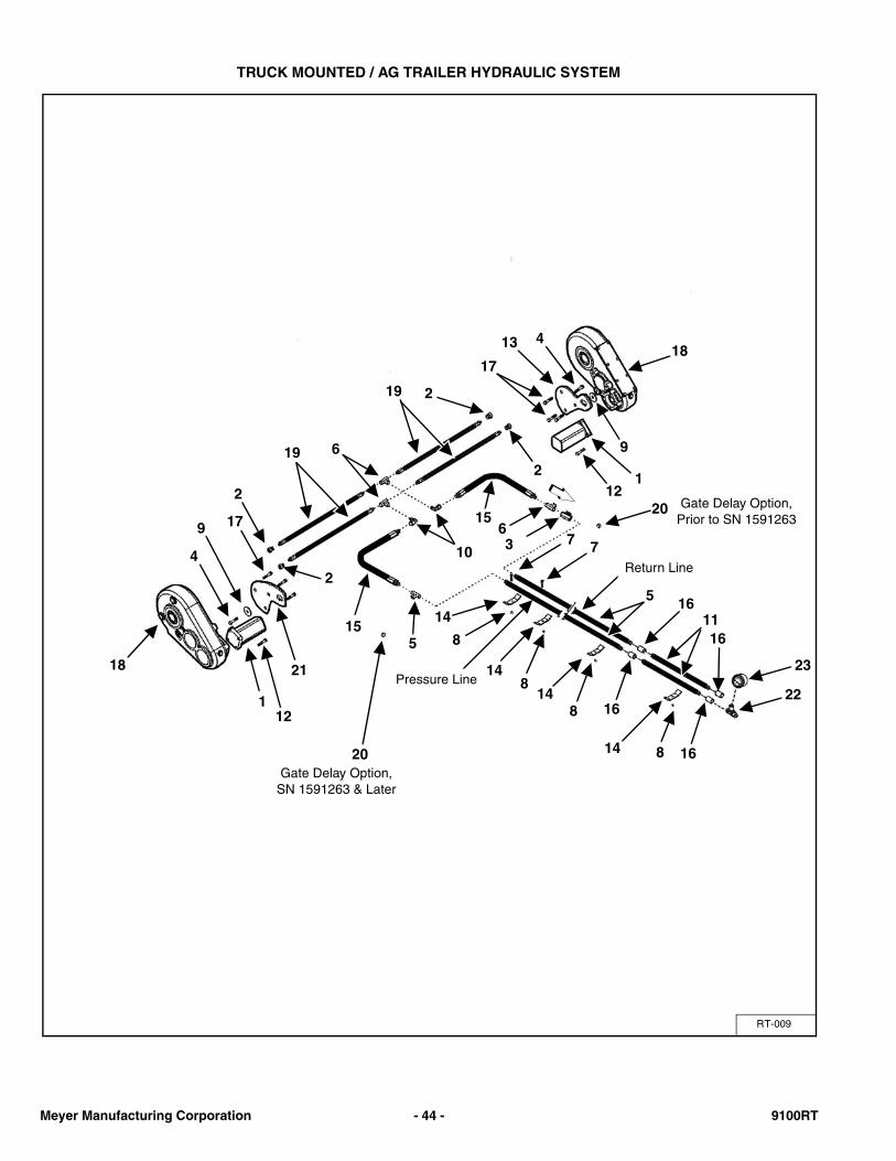
TRUCK MOUNTED / AG TRAILER HYDRAULIC SYSTEM
RT-009
413
11
17
2
2 1
18
9
12
6
18
17
4
9
2
112
21
2
15
20
5
10
15
36
Pressure Line
14
8
8
16
77
Return Line
5 16
16
16
148
14
14 8
19
19
20
23
22
Gate Delay Option, SN 1591263 & Later
Gate Delay Option, Prior to SN 1591263
Meyer Manufacturing Corporation - 44 - 9100RT
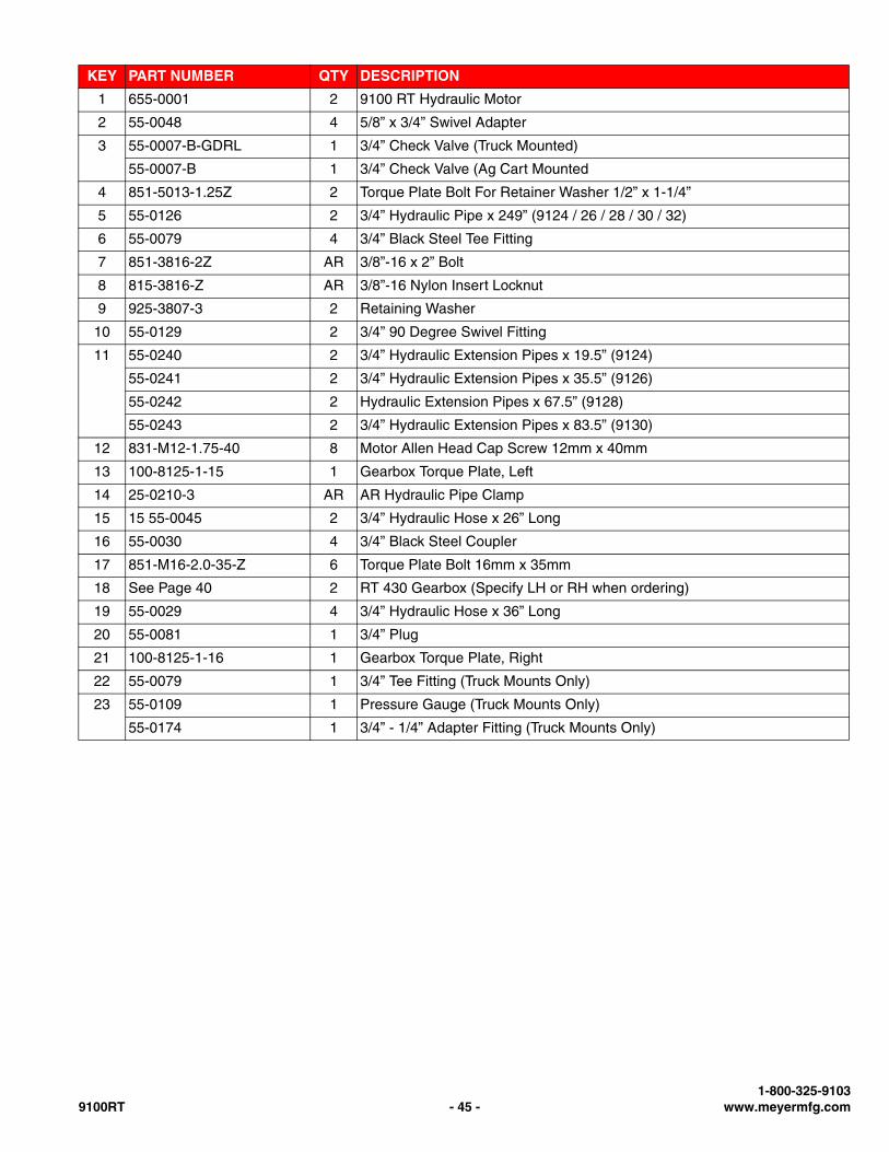
KEY PART NUMBER QTY DESCRIPTION
1 655-0001 2 9100 RT Hydraulic Motor
2 55-0048 4 5/8” x 3/4” Swivel Adapter
3 55-0007-B-GDRL 1 3/4” Check Valve (Truck Mounted)
55-0007-B 1 3/4” Check Valve (Ag Cart Mounted
4 851-5013-1.25Z 2 Torque Plate Bolt For Retainer Washer 1/2” x 1-1/4”
5 55-0126 2 3/4” Hydraulic Pipe x 249” (9124 / 26 / 28 / 30 / 32)
6 55-0079 4 3/4” Black Steel Tee Fitting
7 851-3816-2Z AR 3/8”-16 x 2” Bolt
8 815-3816-Z AR 3/8”-16 Nylon Insert Locknut
9 925-3807-3 2 Retaining Washer
10 55-0129 2 3/4” 90 Degree Swivel Fitting
11 55-0240 2 3/4” Hydraulic Extension Pipes x 19.5” (9124)
55-0241 2 3/4” Hydraulic Extension Pipes x 35.5” (9126)
55-0242 2 Hydraulic Extension Pipes x 67.5” (9128)
55-0243 2 3/4” Hydraulic Extension Pipes x 83.5” (9130)
12 831-M12-1.75-40 8 Motor Allen Head Cap Screw 12mm x 40mm
13 100-8125-1-15 1 Gearbox Torque Plate, Left
14 25-0210-3 AR AR Hydraulic Pipe Clamp
15 15 55-0045 2 3/4” Hydraulic Hose x 26” Long
16 55-0030 4 3/4” Black Steel Coupler
17 851-M16-2.0-35-Z 6 Torque Plate Bolt 16mm x 35mm
18 See Page 40 2 RT 430 Gearbox (Specify LH or RH when ordering)
19 55-0029 4 3/4” Hydraulic Hose x 36” Long
20 55-0081 1 3/4” Plug
21 100-8125-1-16 1 Gearbox Torque Plate, Right
22 55-0079 1 3/4” Tee Fitting (Truck Mounts Only)
23 55-0109 1 Pressure Gauge (Truck Mounts Only)
55-0174 1 3/4” - 1/4” Adapter Fitting (Truck Mounts Only)
1-800-325-91039100RT - 45 - www.meyermfg.com
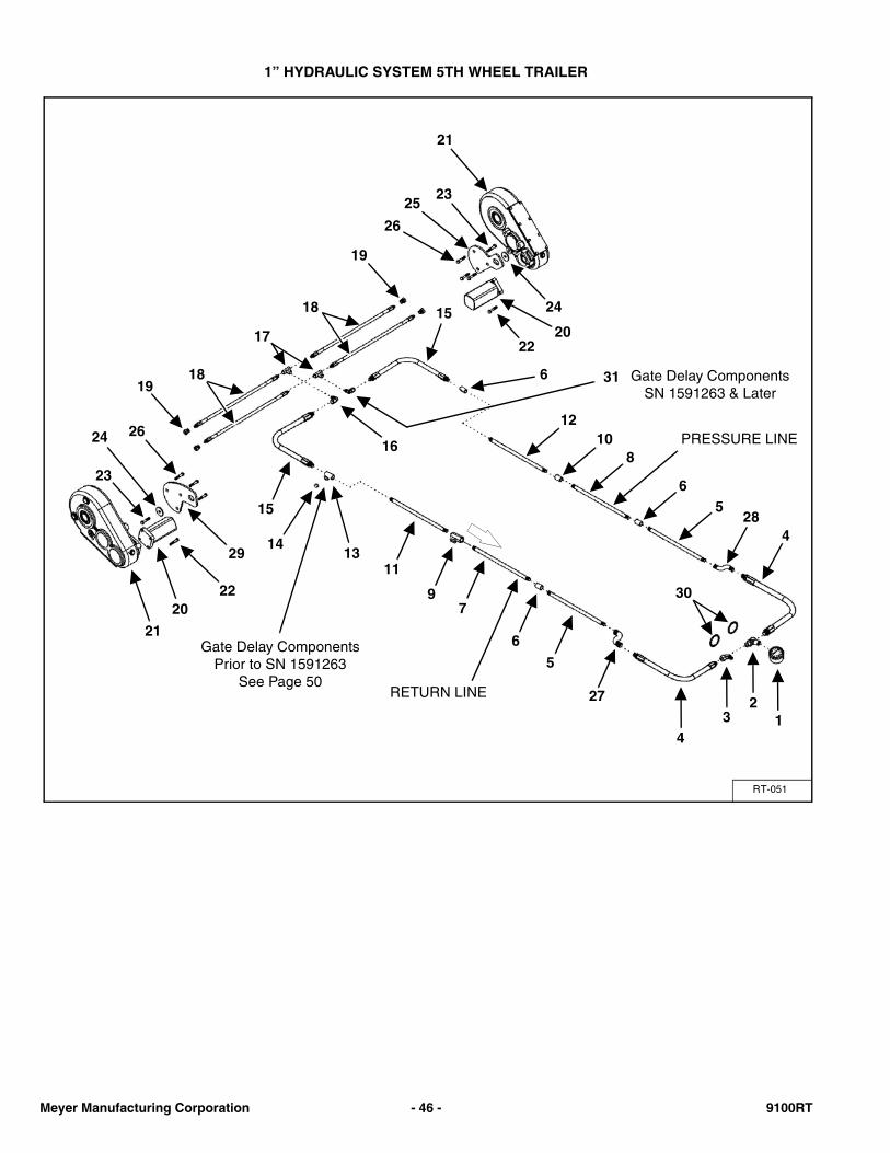
1” HYDRAULIC SYSTEM 5TH WHEEL TRAILER
RT-051
21
2325
26
24
2022
15
1314 4
285
6
810
12
30
12
34
16
15
6
6
5
27
79
11
RETURN LINE
PRESSURE LINE
Gate Delay ComponentsPrior to SN 1591263
See Page 50
29
2220
21
23
24 26
1918
19
18
17
31 Gate Delay ComponentsSN 1591263 & Later
Meyer Manufacturing Corporation - 46 - 9100RT
KEY PART NUMBER QTY DESCRIPTION
1 55-0109 1 Pressure Gauge
2 155-2701-16-LN 1 1-5/16”-12 JIC 90 Degree Bulkhead Fitting, Drilled & Tapped
3 155-2701-16-LNA 1 1-5/16”-12 JIC 90 Degree Bulkhead Fitting
4 155-16100R12-41-1 2 1” Hydraulic Hose x 41”
5 155-16100R12-35-1 2 1” Hydraulic Hose x 35” (Prior to Serial # 1391220)
6 155-2405-16-16 3 1-5/16”-12 JIC x 1” NPTF Female Adapter Fitting
7 55-0260 1 1” Hydraulic Extension Pipe x 21.5” (9130T) (Prior to Serial # 1391220)
55-0265 1 1” Hydraulic Extension Pipe x 51.5” (9130T) (Serial # 1391220 & Later)
55-0256 1 1” Hydraulic Extension Pipe x 101.5” (9136T) (Prior to Serial # 1391220)
55-0264 1 1” Hydraulic Extension Pipe x 131.5” (9136T) (Serial # 1391220 & Later)
55-0251 1 1” Hydraulic Extension Pipe x 141.5” (9140T) (Prior to Serial # 1391220)
55-0263 1 1” Hydraulic Extension Pipe x 171.5” (9140T) (Serial # 1391220 & Later)
8 55-0259 1 1” Hydraulic Extension Pipe x 24” (9130T) (Prior to Serial # 1391220)
55-0265 1 1” Hydraulic Extension Pipe x 51.5” (9130T) (Serial # 1391220 & Later)
55-0255 1 1” Hydraulic Extension Pipe x 104” (9130T) (Serial # 1391220 & Later)
55-0264 1 1” Hydraulic Extension Pipe x 131.5” (9136T) (Serial # 1391220 & Later)
55-0250 1 1” Hydraulic Extension Pipe x 144” (9140T) (Prior to Serial # 1391220)
55-0263 1 1” Hydraulic Extension Pipe x 171.5” (9140T) (Serial # 1391220 & Later)
9 955-4005-1 1 1” Check Valve
10 155-5000-16-16 1 1” Coupler
11 955-8018 1 1” Hydraulic Pipe x 252” (9130T / 36T / 40T) (Prior to Serial # 1391220)
55-0262 1 1” Hydraulic Pipe x 249” (9130T / 36T / 40T) (Serial # 1391220 & Later)
12 955-8018 1 1” Hydraulic Pipe x 252” (9130T / 36T / 40T) (Prior to Serial # 1391220)
955-8018 1 1” Hydraulic Pipe x 249” (9130T / 36T / 40T) (Serial # 1391220 & Later)
13 155-2606-16-16-16 1 1” Tee Fitting, Drilled & Tapped 3/8” NPT
14 155-304-C-16 1 1-5/16”-12 JIC Cap
15 155-16100R12-75-1 2 1” Hydraulic Hose x 75” Long
16 155-6500-16 2 1-5/16”-12 JIC 90 Degree Swivel Fitting
17 155-2603-16 2 1-5/16”-12 JIC Tee Fitting
18 155-12100R12-36-1 4 3/4” Hydraulic Hose x 36” Long
19 155-6400-16-10 4 1-5/16”-12 JIC To 7/8” Adapter Fitting
20 655-0001 2 9100 RT Hydraulic Motor
21 19-0204 2 RT 430 Gearbox (Specify LH or RH When Ordering)
22 831-M12-1.75-40 8 Motor Allen Head Cap Screw 12mm x 40mm
23 851-5013-1.25Z 2 Torque Plate Bolt For Retainer Washer 1/2” x 1-1/4”
24 925-3807-3 2 Retaining Washer
25 100-8125-1-15 1 Gearbox Torque Plate, Left
26 851-M16-2.0-35-Z 6 Torque Plate Bolt 16mm x 35mm
27 55-0234 1 1” 90 Degree Fitting (Prior to Serial # 1391220)
55-0235 1 Female Right Hand Sweep (Serial # 1391220 & Later)
28 55-0234 1 1” 90 Degree Fitting (Prior to Serial # 1391220)
55-0236 1 Female Left Hand Sweep (Serial # 1391220 & Later)
29 100-8125-1-16 1 Gearbox Torque Plate, Right
30 806-0125-Z 2 1-1/4” Internal Tooth Lock Washer
31 155-6500-16 1 1-5/16”-12 JIC 90° Swivel Fitting (Prior to SN 1591263)
155-6600-16-16-16 1 Swivel Tee (SN 1591263 & Later)
1-800-325-91039100RT - 47 - www.meyermfg.com

REAR DOOR
RT-025
13
17
16
18
10
9
8
15
17
19
1211
14
7
8A
6
43
21
5
2021
13
Meyer Manufacturing Corporation - 48 - 9100RT
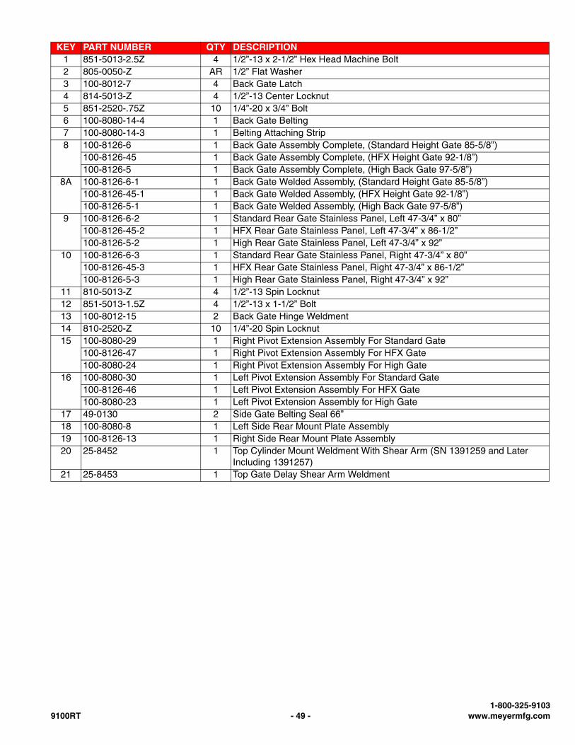
KEY PART NUMBER QTY DESCRIPTION1 851-5013-2.5Z 4 1/2”-13 x 2-1/2” Hex Head Machine Bolt2 805-0050-Z AR 1/2” Flat Washer3 100-8012-7 4 Back Gate Latch4 814-5013-Z 4 1/2”-13 Center Locknut5 851-2520-.75Z 10 1/4”-20 x 3/4” Bolt6 100-8080-14-4 1 Back Gate Belting7 100-8080-14-3 1 Belting Attaching Strip8 100-8126-6 1 Back Gate Assembly Complete, (Standard Height Gate 85-5/8”)
100-8126-45 1 Back Gate Assembly Complete, (HFX Height Gate 92-1/8”)100-8126-5 1 Back Gate Assembly Complete, (High Back Gate 97-5/8”)
8A 100-8126-6-1 1 Back Gate Welded Assembly, (Standard Height Gate 85-5/8”)100-8126-45-1 1 Back Gate Welded Assembly, (HFX Height Gate 92-1/8”)100-8126-5-1 1 Back Gate Welded Assembly, (High Back Gate 97-5/8”)
9 100-8126-6-2 1 Standard Rear Gate Stainless Panel, Left 47-3/4” x 80”100-8126-45-2 1 HFX Rear Gate Stainless Panel, Left 47-3/4” x 86-1/2”100-8126-5-2 1 High Rear Gate Stainless Panel, Left 47-3/4” x 92”
10 100-8126-6-3 1 Standard Rear Gate Stainless Panel, Right 47-3/4” x 80”100-8126-45-3 1 HFX Rear Gate Stainless Panel, Right 47-3/4” x 86-1/2”100-8126-5-3 1 High Rear Gate Stainless Panel, Right 47-3/4” x 92”
11 810-5013-Z 4 1/2”-13 Spin Locknut12 851-5013-1.5Z 4 1/2”-13 x 1-1/2” Bolt13 100-8012-15 2 Back Gate Hinge Weldment14 810-2520-Z 10 1/4”-20 Spin Locknut15 100-8080-29 1 Right Pivot Extension Assembly For Standard Gate
100-8126-47 1 Right Pivot Extension Assembly For HFX Gate100-8080-24 1 Right Pivot Extension Assembly For High Gate
16 100-8080-30 1 Left Pivot Extension Assembly For Standard Gate100-8126-46 1 Left Pivot Extension Assembly For HFX Gate100-8080-23 1 Left Pivot Extension Assembly for High Gate
17 49-0130 2 Side Gate Belting Seal 66”18 100-8080-8 1 Left Side Rear Mount Plate Assembly19 100-8126-13 1 Right Side Rear Mount Plate Assembly20 25-8452 1 Top Cylinder Mount Weldment With Shear Arm (SN 1391259 and Later
Including 1391257)21 25-8453 1 Top Gate Delay Shear Arm Weldment
1-800-325-91039100RT - 49 - www.meyermfg.com
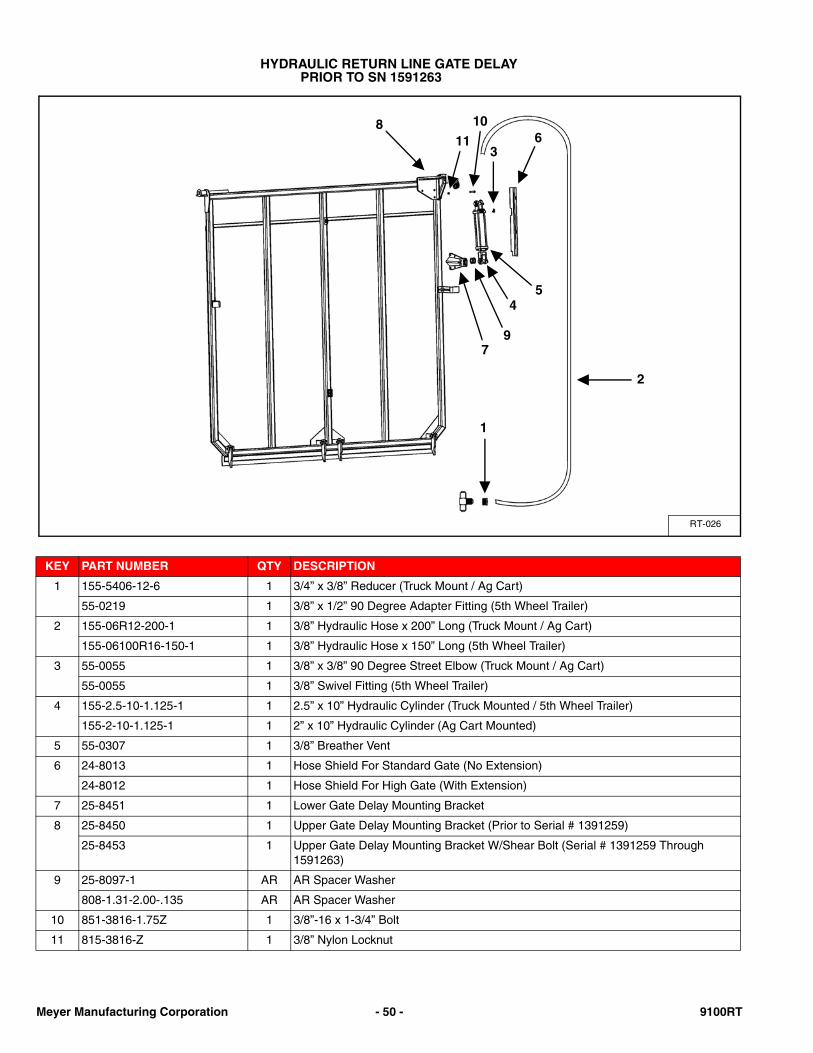
HYDRAULIC RETURN LINE GATE DELAYPRIOR TO SN 1591263
KEY PART NUMBER QTY DESCRIPTION
1 155-5406-12-6 1 3/4” x 3/8” Reducer (Truck Mount / Ag Cart)
55-0219 1 3/8” x 1/2” 90 Degree Adapter Fitting (5th Wheel Trailer)
2 155-06R12-200-1 1 3/8” Hydraulic Hose x 200” Long (Truck Mount / Ag Cart)
155-06100R16-150-1 1 3/8” Hydraulic Hose x 150” Long (5th Wheel Trailer)
3 55-0055 1 3/8” x 3/8” 90 Degree Street Elbow (Truck Mount / Ag Cart)
55-0055 1 3/8” Swivel Fitting (5th Wheel Trailer)
4 155-2.5-10-1.125-1 1 2.5” x 10” Hydraulic Cylinder (Truck Mounted / 5th Wheel Trailer)
155-2-10-1.125-1 1 2” x 10” Hydraulic Cylinder (Ag Cart Mounted)
5 55-0307 1 3/8” Breather Vent
6 24-8013 1 Hose Shield For Standard Gate (No Extension)
24-8012 1 Hose Shield For High Gate (With Extension)
7 25-8451 1 Lower Gate Delay Mounting Bracket
8 25-8450 1 Upper Gate Delay Mounting Bracket (Prior to Serial # 1391259)
25-8453 1 Upper Gate Delay Mounting Bracket W/Shear Bolt (Serial # 1391259 Through 1591263)
9 25-8097-1 AR AR Spacer Washer
808-1.31-2.00-.135 AR AR Spacer Washer
10 851-3816-1.75Z 1 3/8”-16 x 1-3/4” Bolt
11 815-3816-Z 1 3/8” Nylon Locknut
RT-026
1
2
811
10
36
4
97
5
Meyer Manufacturing Corporation - 50 - 9100RT
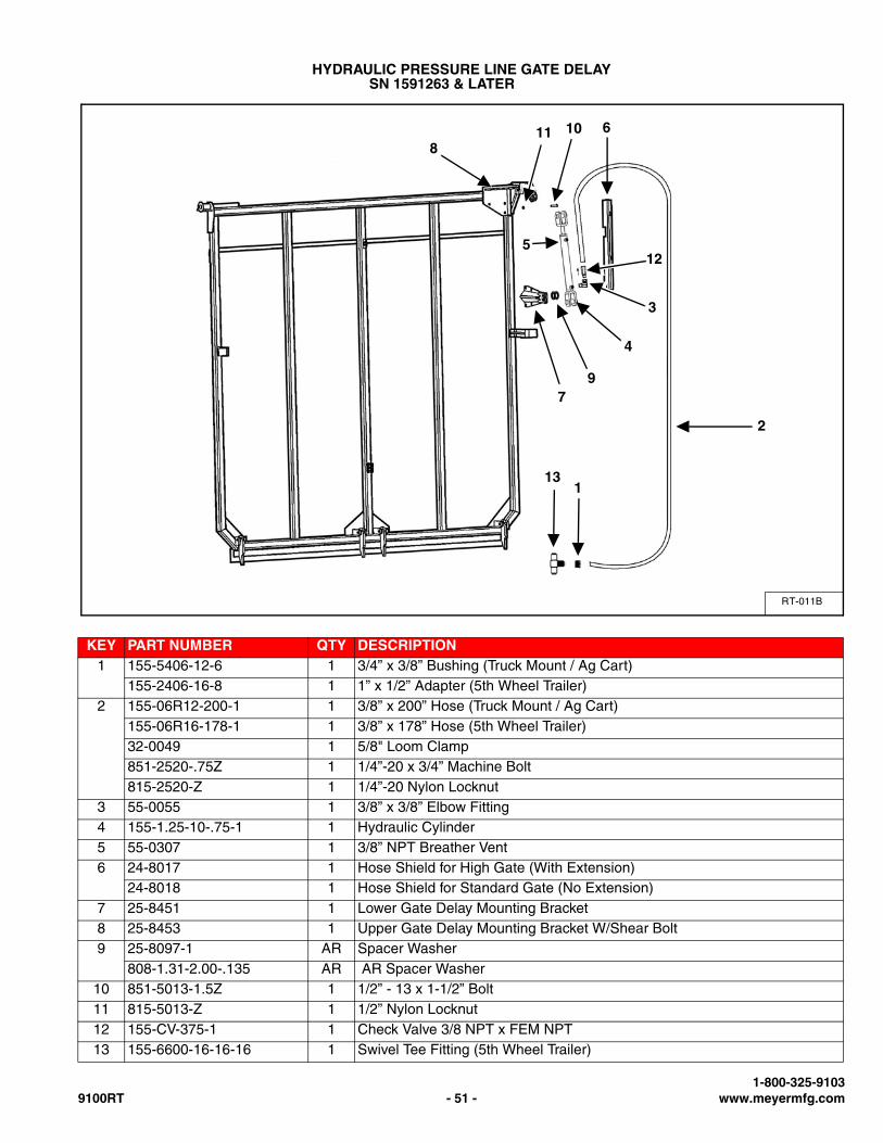
HYDRAULIC PRESSURE LINE GATE DELAYSN 1591263 & LATER
KEY PART NUMBER QTY DESCRIPTION1 155-5406-12-6 1 3/4” x 3/8” Bushing (Truck Mount / Ag Cart)
155-2406-16-8 1 1” x 1/2” Adapter (5th Wheel Trailer)2 155-06R12-200-1 1 3/8” x 200” Hose (Truck Mount / Ag Cart)
155-06R16-178-1 1 3/8” x 178” Hose (5th Wheel Trailer)32-0049 1 5/8" Loom Clamp851-2520-.75Z 1 1/4”-20 x 3/4” Machine Bolt815-2520-Z 1 1/4”-20 Nylon Locknut
3 55-0055 1 3/8” x 3/8” Elbow Fitting4 155-1.25-10-.75-1 1 Hydraulic Cylinder5 55-0307 1 3/8” NPT Breather Vent6 24-8017 1 Hose Shield for High Gate (With Extension)
24-8018 1 Hose Shield for Standard Gate (No Extension)7 25-8451 1 Lower Gate Delay Mounting Bracket8 25-8453 1 Upper Gate Delay Mounting Bracket W/Shear Bolt9 25-8097-1 AR Spacer Washer
808-1.31-2.00-.135 AR AR Spacer Washer10 851-5013-1.5Z 1 1/2” - 13 x 1-1/2” Bolt11 815-5013-Z 1 1/2” Nylon Locknut12 155-CV-375-1 1 Check Valve 3/8 NPT x FEM NPT13 155-6600-16-16-16 1 Swivel Tee Fitting (5th Wheel Trailer)
RT-011B
1
2
811 10
3
6
4
97
512
13
1-800-325-91039100RT - 51 - www.meyermfg.com
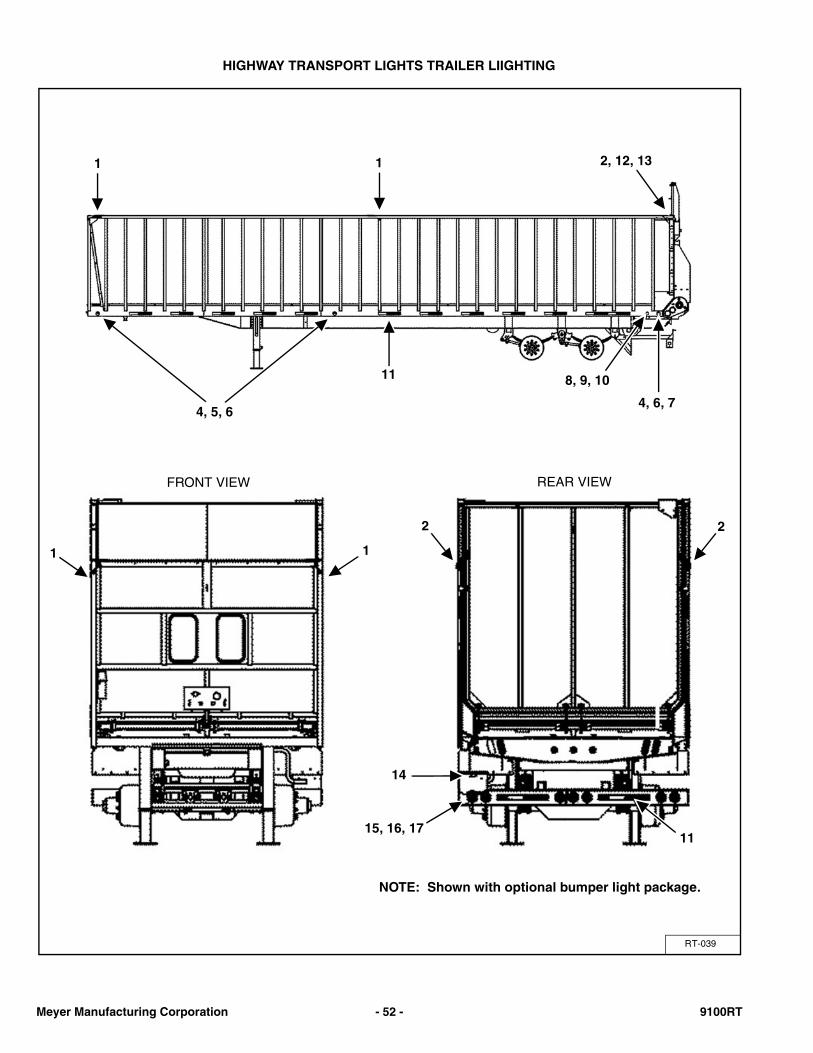
HIGHWAY TRANSPORT LIGHTS TRAILER LIIGHTING
RT-039
1 2, 12, 13
REAR VIEWFRONT VIEW
1
2
1
4, 5, 6
11
14
15, 16, 17
1
11
4, 6, 7
2
8, 9, 10
NOTE: Shown with optional bumper light package.
Meyer Manufacturing Corporation - 52 - 9100RT
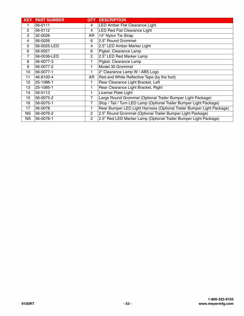
KEY PART NUMBER QTY DESCRIPTION1 56-0111 4 LED Amber Flat Clearance Light2 56-0112 4 LED Red Flat Clearance Light3 32-0026 AR 14” Nylon Tie Strap4 56-0026 6 2.5” Round Grommet5 56-0025-LED 4 2.5” LED Amber Marker Light6 56-0027 6 Pigtail, Clearance Lamp7 56-0036-LED 2 2.5” LED Red Marker Lamp8 56-0077-3 1 Pigtail, Clearance Lamp9 56-0077-2 1 Model 30 Grommet
10 56-0077-1 1 2” Clearance Lamp W / ABS Logo11 46-8100-4 AR Red and White Reflective Tape (by the foot)12 25-1086-1 1 Rear Clearance Light Bracket, Left13 25-1085-1 1 Rear Clearance Light Bracket, Right14 56-0113 1 License Plate Light15 56-0075-2 7 Large Round Grommet (Optional Trailer Bumper Light Package)16 56-0075-1 7 Stop / Tail / Turn LED Lamp (Optional Trailer Bumper Light Package)17 56-0078 1 Rear Bumper LED Light Harness (Optional Trailer Bumper Light Package)NS 56-0076-2 2 2.5” Round Grommet (Optional Trailer Bumper Light Package)NS 56-0076-1 2 2.5” Red LED Marker Lamp (Optional Trailer Bumper Light Package)
1-800-325-91039100RT - 53 - www.meyermfg.com
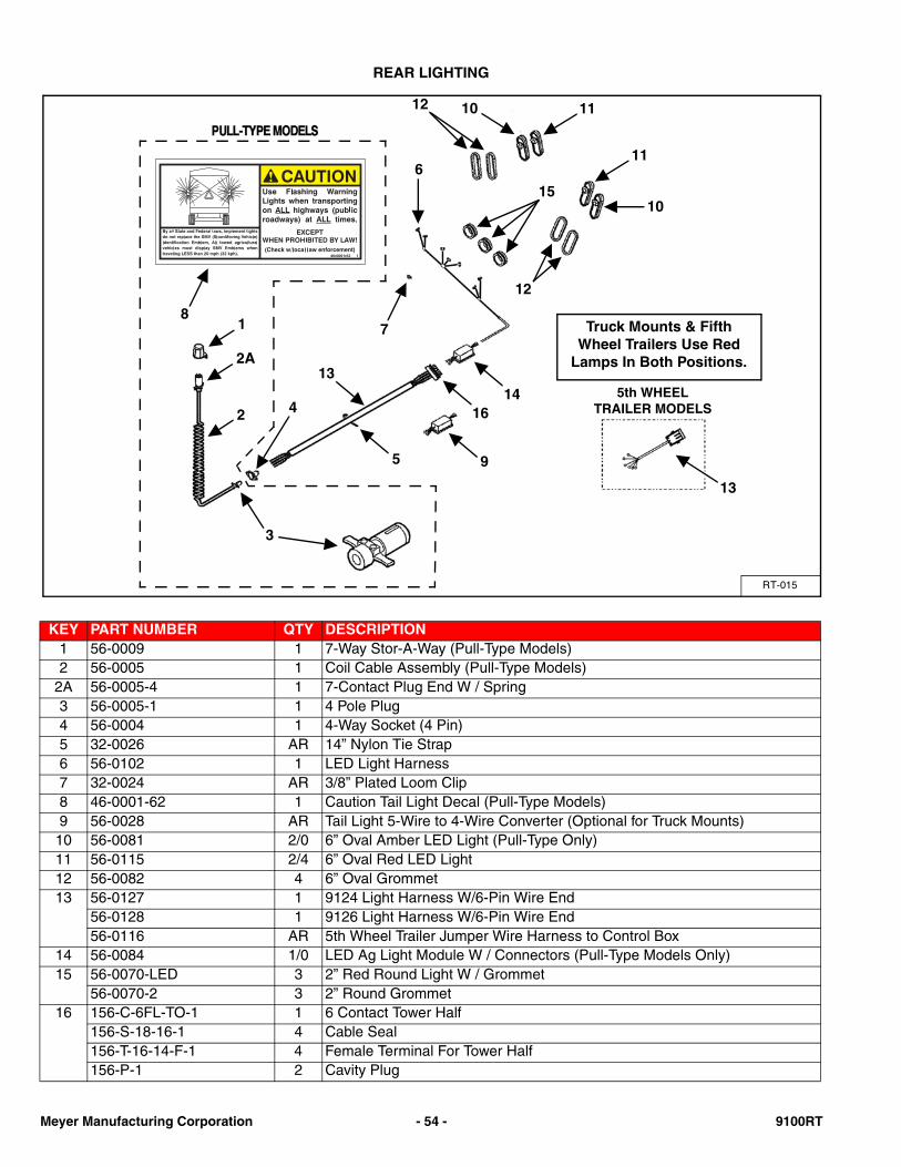
REAR LIGHTING
KEY PART NUMBER QTY DESCRIPTION1 56-0009 1 7-Way Stor-A-Way (Pull-Type Models)2 56-0005 1 Coil Cable Assembly (Pull-Type Models)
2A 56-0005-4 1 7-Contact Plug End W / Spring3 56-0005-1 1 4 Pole Plug4 56-0004 1 4-Way Socket (4 Pin)5 32-0026 AR 14” Nylon Tie Strap6 56-0102 1 LED Light Harness7 32-0024 AR 3/8” Plated Loom Clip8 46-0001-62 1 Caution Tail Light Decal (Pull-Type Models)9 56-0028 AR Tail Light 5-Wire to 4-Wire Converter (Optional for Truck Mounts)
10 56-0081 2/0 6” Oval Amber LED Light (Pull-Type Only)11 56-0115 2/4 6” Oval Red LED Light12 56-0082 4 6” Oval Grommet13 56-0127 1 9124 Light Harness W/6-Pin Wire End
56-0128 1 9126 Light Harness W/6-Pin Wire End56-0116 AR 5th Wheel Trailer Jumper Wire Harness to Control Box
14 56-0084 1/0 LED Ag Light Module W / Connectors (Pull-Type Models Only)15 56-0070-LED 3 2” Red Round Light W / Grommet
56-0070-2 3 2” Round Grommet16 156-C-6FL-TO-1 1 6 Contact Tower Half
156-S-18-16-1 4 Cable Seal156-T-16-14-F-1 4 Female Terminal For Tower Half156-P-1 2 Cavity Plug
RT-015
12 10
11
15
6
7
10
11
12
13
1614
95
81
2A
2
3
4
Truck Mounts & Fifth Wheel Trailers Use Red
Lamps In Both Positions.
5th WHEEL TRAILER MODELS
13
Meyer Manufacturing Corporation - 54 - 9100RT
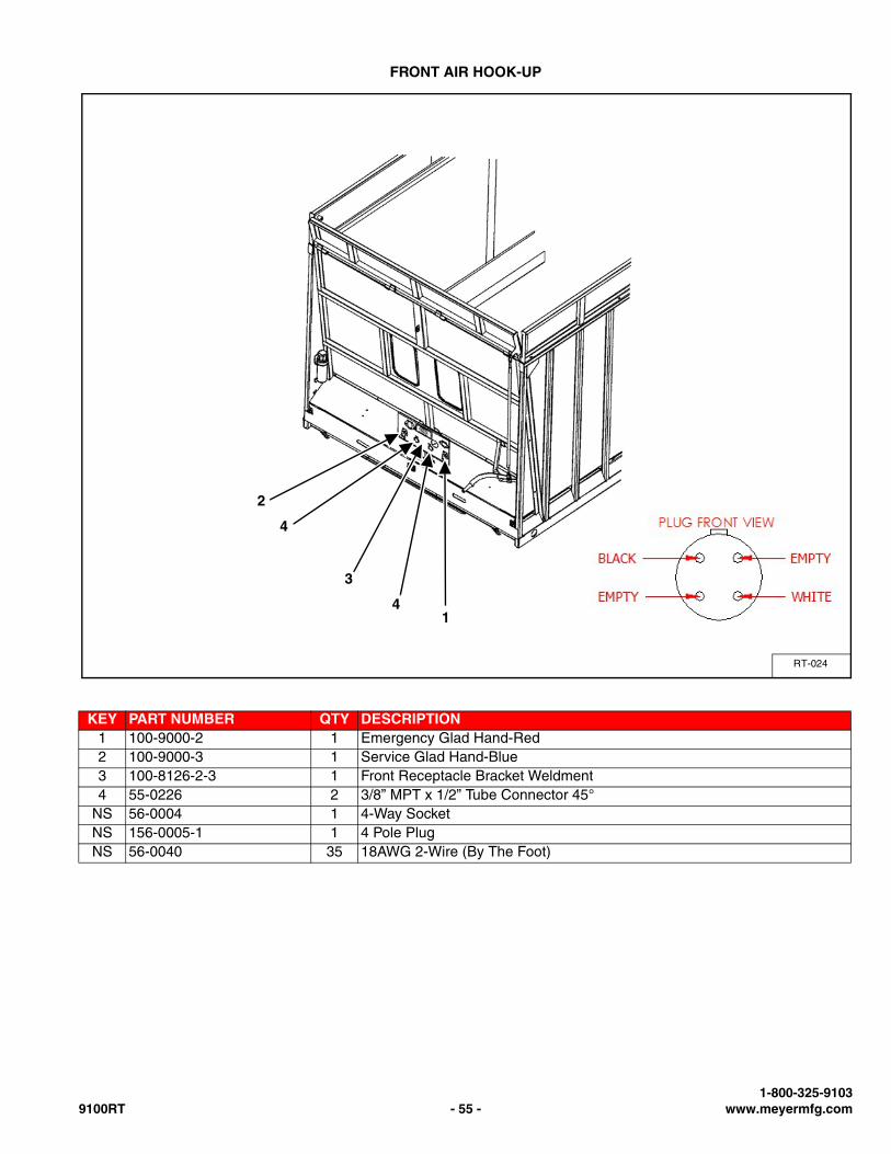
FRONT AIR HOOK-UP
KEY PART NUMBER QTY DESCRIPTION1 100-9000-2 1 Emergency Glad Hand-Red2 100-9000-3 1 Service Glad Hand-Blue3 100-8126-2-3 1 Front Receptacle Bracket Weldment4 55-0226 2 3/8” MPT x 1/2” Tube Connector 45°
NS 56-0004 1 4-Way SocketNS 156-0005-1 1 4 Pole PlugNS 56-0040 35 18AWG 2-Wire (By The Foot)
RT-024
14
3
4
2
1-800-325-91039100RT - 55 - www.meyermfg.com
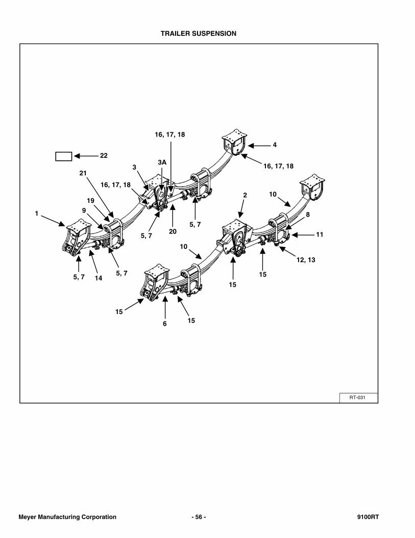
TRAILER SUSPENSION
RT-031
4
16, 17, 18
8
115, 7
12, 13
33A
10
919
21
1
15
5, 7
2
205, 7
145, 7
10
6
15
15
15
16, 17, 18
16, 17, 18
22
Meyer Manufacturing Corporation - 56 - 9100RT
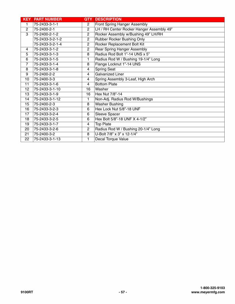
KEY PART NUMBER QTY DESCRIPTION1 75-2433-3-1-1 2 Front Spring Hanger Assembly2 75-2400-2-1 2 LH / RH Center Rocker Hanger Assembly 49”3 75-2400-2-1-2 2 Rocker Assembly w/Bushing 49” LH/RH
75-2433-3-2-1-2 2 Rubber Rocker Bushing Only75-2433-3-2-1-4 2 Rocker Replacement Bolt Kit
4 75-2433-3-1-2 2 Rear Spring Hanger Assembly5 75-2433-3-1-3 8 Radius Rod Bolt 1”-14 UNS x 5”6 75-2433-3-1-5 1 Radius Rod W / Bushing 19-1/4” Long7 75-2433-3-1-4 8 Flange Locknut 1”-14 UNS8 75-2433-3-1-8 4 Spring Seat9 75-2400-2-2 4 Galvanized Liner
10 75-2400-3-3 4 Spring Assembly 3-Leaf, High Arch11 75-2433-3-1-6 4 Bottom Plate12 75-2433-3-1-10 16 Washer13 75-2433-3-1-9 16 Hex Nut 7/8”-1414 75-2433-3-1-12 1 Non-Adj. Radius Rod W/Bushings15 75-2400-2-3 8 Washer Bushing16 75-2433-3-2-3 6 Hex Lock Nut 5/8”-18 UNF17 75-2433-3-2-4 6 Sleeve Spacer18 75-2433-3-2-5 6 Hex Bolt 5/8”-18 UNF X 4-1/2”19 75-2433-3-1-7 4 Top Plate20 75-2433-3-2-6 2 Radius Rod W / Bushing 20-1/4” Long21 75-2400-3-2 8 U-Bolt 7/8” x 3” x 12-1/4”22 75-2433-3-1-13 1 Decal Torque Value
1-800-325-91039100RT - 57 - www.meyermfg.com
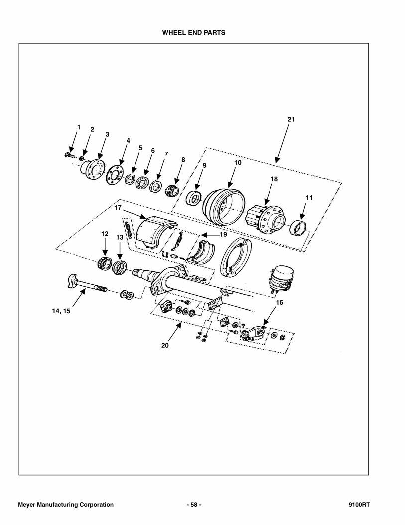
WHEEL END PARTS
211 2
34
5 6 78
9 10
18
17
19
11
12 13
14, 15
20
16
Meyer Manufacturing Corporation - 58 - 9100RT
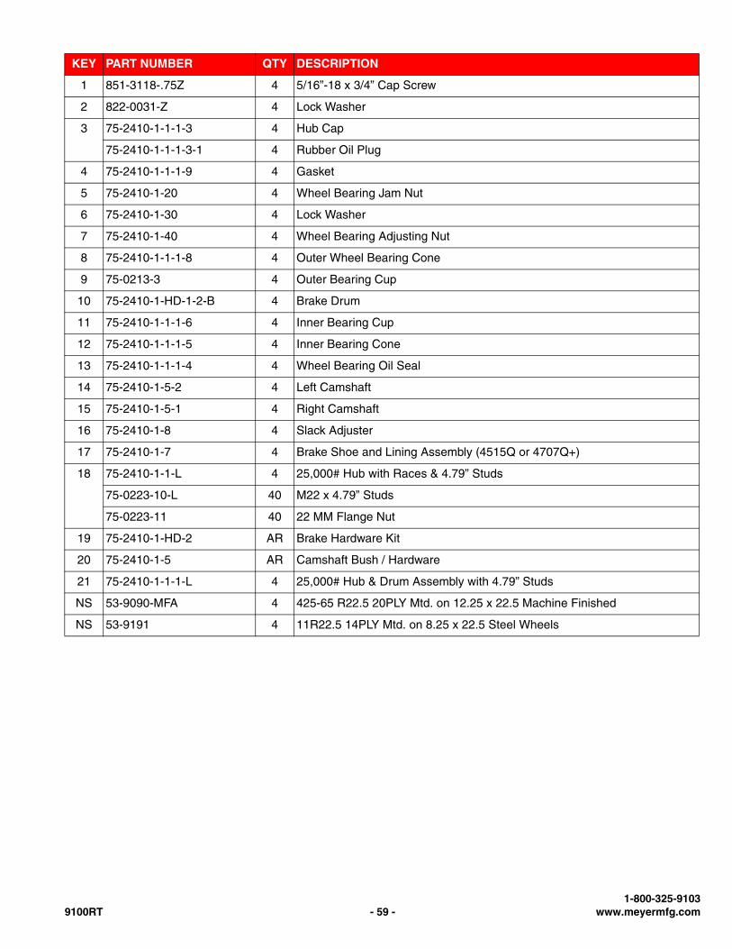
KEY PART NUMBER QTY DESCRIPTION
1 851-3118-.75Z 4 5/16”-18 x 3/4” Cap Screw
2 822-0031-Z 4 Lock Washer
3 75-2410-1-1-1-3 4 Hub Cap
75-2410-1-1-1-3-1 4 Rubber Oil Plug
4 75-2410-1-1-1-9 4 Gasket
5 75-2410-1-20 4 Wheel Bearing Jam Nut
6 75-2410-1-30 4 Lock Washer
7 75-2410-1-40 4 Wheel Bearing Adjusting Nut
8 75-2410-1-1-1-8 4 Outer Wheel Bearing Cone
9 75-0213-3 4 Outer Bearing Cup
10 75-2410-1-HD-1-2-B 4 Brake Drum
11 75-2410-1-1-1-6 4 Inner Bearing Cup
12 75-2410-1-1-1-5 4 Inner Bearing Cone
13 75-2410-1-1-1-4 4 Wheel Bearing Oil Seal
14 75-2410-1-5-2 4 Left Camshaft
15 75-2410-1-5-1 4 Right Camshaft
16 75-2410-1-8 4 Slack Adjuster
17 75-2410-1-7 4 Brake Shoe and Lining Assembly (4515Q or 4707Q+)
18 75-2410-1-1-L 4 25,000# Hub with Races & 4.79” Studs
75-0223-10-L 40 M22 x 4.79” Studs
75-0223-11 40 22 MM Flange Nut
19 75-2410-1-HD-2 AR Brake Hardware Kit
20 75-2410-1-5 AR Camshaft Bush / Hardware
21 75-2410-1-1-1-L 4 25,000# Hub & Drum Assembly with 4.79” Studs
NS 53-9090-MFA 4 425-65 R22.5 20PLY Mtd. on 12.25 x 22.5 Machine Finished
NS 53-9191 4 11R22.5 14PLY Mtd. on 8.25 x 22.5 Steel Wheels
1-800-325-91039100RT - 59 - www.meyermfg.com
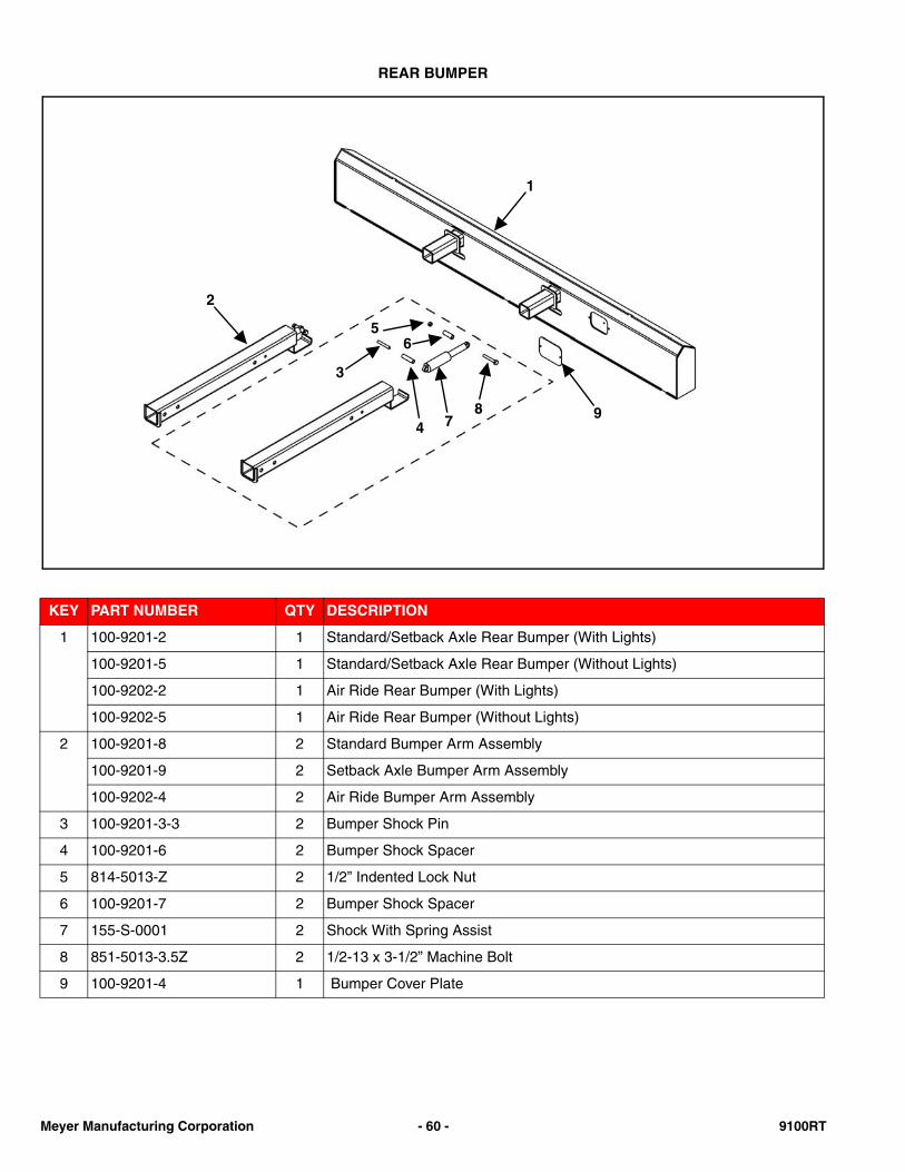
REAR BUMPER
KEY PART NUMBER QTY DESCRIPTION
1 100-9201-2 1 Standard/Setback Axle Rear Bumper (With Lights)
100-9201-5 1 Standard/Setback Axle Rear Bumper (Without Lights)
100-9202-2 1 Air Ride Rear Bumper (With Lights)
100-9202-5 1 Air Ride Rear Bumper (Without Lights)
2 100-9201-8 2 Standard Bumper Arm Assembly
100-9201-9 2 Setback Axle Bumper Arm Assembly
100-9202-4 2 Air Ride Bumper Arm Assembly
3 100-9201-3-3 2 Bumper Shock Pin
4 100-9201-6 2 Bumper Shock Spacer
5 814-5013-Z 2 1/2” Indented Lock Nut
6 100-9201-7 2 Bumper Shock Spacer
7 155-S-0001 2 Shock With Spring Assist
8 851-5013-3.5Z 2 1/2-13 x 3-1/2” Machine Bolt
9 100-9201-4 1 Bumper Cover Plate
1
2
56
4
3
78 9
Meyer Manufacturing Corporation - 60 - 9100RT
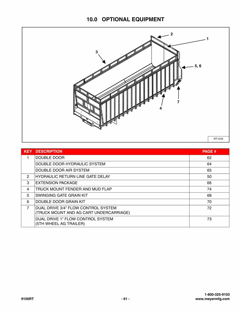
10.0 OPTIONAL EQUIPMENT
KEY DESCRIPTION PAGE #
1 DOUBLE DOOR 62
DOUBLE DOOR HYDRAULIC SYSTEM 64
DOUBLE DOOR AIR SYSTEM 65
2 HYDRAULIC RETURN LINE GATE DELAY 50
3 EXTENSION PACKAGE 66
4 TRUCK MOUNT FENDER AND MUD FLAP 74
5 SWINGING GATE GRAIN KIT 68
6 DOUBLE DOOR GRAIN KIT 70
7 DUAL DRIVE 3/4” FLOW CONTROL SYSTEM(TRUCK MOUNT AND AG CART UNDERCARRIAGE)
72
DUAL DRIVE 1” FLOW CONTROL SYSTEM(5TH WHEEL AG TRAILER)
73
RT-018
12
3
4
5, 6
7
1-800-325-91039100RT - 61 - www.meyermfg.com
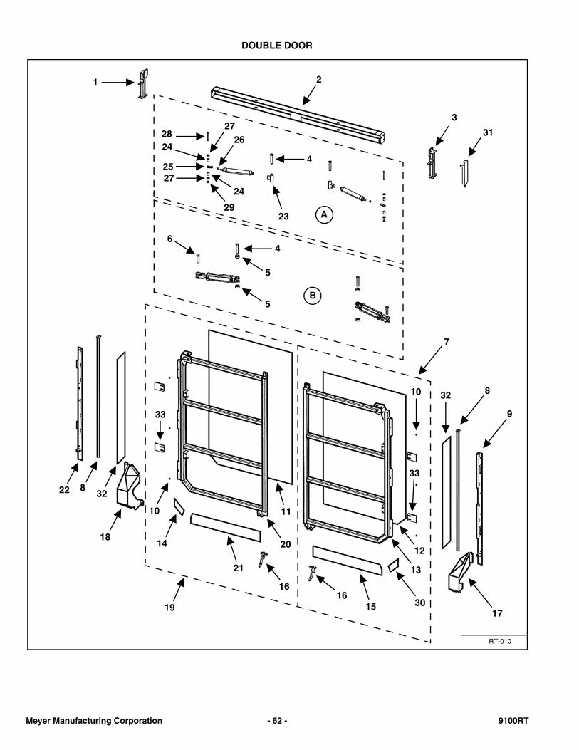
DOUBLE DOOR
RT-010
1 2
3
312827
24
25
29
26
4
2724
4
5
6
5
33
12
13
10 32 8
9
173015
1616
21
11
2014
10
33
22 832
18
7
19
23 A
B
Meyer Manufacturing Corporation - 62 - 9100RT
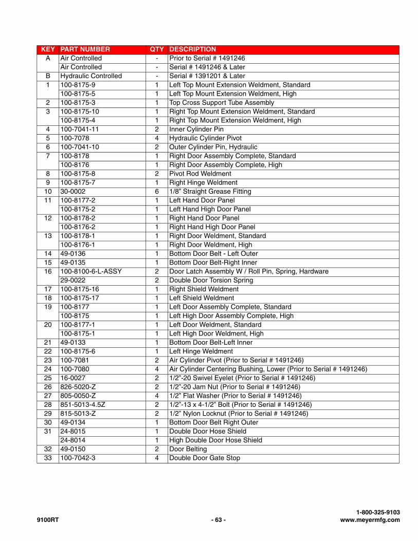
KEY PART NUMBER QTY DESCRIPTIONA Air Controlled - Prior to Serial # 1491246
Air Controlled - Serial # 1491246 & LaterB Hydraulic Controlled - Serial # 1391201 & Later1 100-8175-9 1 Left Top Mount Extension Weldment, Standard
100-8175-5 1 Left Top Mount Extension Weldment, High2 100-8175-3 1 Top Cross Support Tube Assembly3 100-8175-10 1 Right Top Mount Extension Weldment, Standard
100-8175-4 1 Right Top Mount Extension Weldment, High4 100-7041-11 2 Inner Cylinder Pin5 100-7078 4 Hydraulic Cylinder Pivot6 100-7041-10 2 Outer Cylinder Pin, Hydraulic7 100-8178 1 Right Door Assembly Complete, Standard
100-8176 1 Right Door Assembly Complete, High8 100-8175-8 2 Pivot Rod Weldment9 100-8175-7 1 Right Hinge Weldment
10 30-0002 6 1/8” Straight Grease Fitting11 100-8177-2 1 Left Hand Door Panel
100-8175-2 1 Left Hand High Door Panel12 100-8178-2 1 Right Hand Door Panel
100-8176-2 1 Right Hand High Door Panel13 100-8178-1 1 Right Door Weldment, Standard
100-8176-1 1 Right Door Weldment, High14 49-0136 1 Bottom Door Belt - Left Outer15 49-0135 1 Bottom Door Belt-Right Inner16 100-8100-6-L-ASSY 2 Door Latch Assembly W / Roll Pin, Spring, Hardware
29-0022 2 Double Door Torsion Spring17 100-8175-16 1 Right Shield Weldment18 100-8175-17 1 Left Shield Weldment19 100-8177 1 Left Door Assembly Complete, Standard
100-8175 1 Left High Door Assembly Complete, High20 100-8177-1 1 Left Door Weldment, Standard
100-8175-1 1 Left High Door Weldment, High21 49-0133 1 Bottom Door Belt-Left Inner22 100-8175-6 1 Left Hinge Weldment23 100-7081 2 Air Cylinder Pivot (Prior to Serial # 1491246)24 100-7080 4 Air Cylinder Centering Bushing, Lower (Prior to Serial # 1491246)25 16-0027 2 1/2”-20 Swivel Eyelet (Prior to Serial # 1491246)26 826-5020-Z 2 1/2”-20 Jam Nut (Prior to Serial # 1491246)27 805-0050-Z 4 1/2” Flat Washer (Prior to Serial # 1491246)28 851-5013-4.5Z 2 1/2”-13 x 4-1/2” Bolt (Prior to Serial # 1491246)29 815-5013-Z 2 1/2” Nylon Locknut (Prior to Serial # 1491246)30 49-0134 1 Bottom Door Belt Right Outer31 24-8015 1 Double Door Hose Shield
24-8014 1 High Double Door Hose Shield32 49-0150 2 Door Belting33 100-7042-3 4 Double Door Gate Stop
1-800-325-91039100RT - 63 - www.meyermfg.com
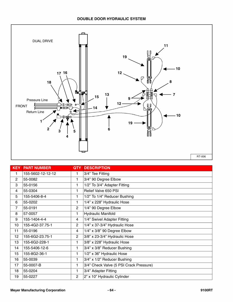
DOUBLE DOOR HYDRAULIC SYSTEM
KEY PART NUMBER QTY DESCRIPTION
1 155-5602-12-12-12 1 3/4” Tee Fitting
2 55-0082 1 3/4” 90 Degree Elbow
3 55-0156 1 1/2” To 3/4” Adapter Fitting
4 55-0304 1 Relief Valve 650 PSI
5 155-5406-8-4 1 1/2” To 1/4” Reducer Bushing
6 55-0202 1 1/4” x 228” Hydraulic Hose
7 55-0191 2 1/4” 90 Degree Elbow
8 57-0057 1 Hydraulic Manifold
9 155-1404-4-4 4 1/4” Swivel Adapter Fitting
10 155-4G2-37.75-1 2 1/4” x 37-3/4” Hydraulic Hose
11 55-0196 4 1/4” x 3/8” 90 Degree Elbow
12 155-6G2-23.75-1 2 3/8” x 23-3/4” Hydraulic Hose
13 155-6G2-228-1 1 3/8” x 228” Hydraulic Hose
14 155-5406-12-6 1 3/4” x 3/8” Reducer Bushing
15 155-8G2-36-1 1 1/2” x 36” Hydraulic Hose
16 55-0039 1 3/4” x 1/2” Reducer Bushing
17 55-0007-B 1 3/4” Check Valve (5 PSI Crack Pressure)
18 55-0204 1 3/4” Adapter Fitting
19 55-0227 2 2” x 10” Hydraulic Cylinder
RT-006
DUAL DRIVE
Return Line
Pressure Line
10
11
19
12
97
8
6
13
19
12
10
15
1617
18
14
1
2 34
5
FRONT
Meyer Manufacturing Corporation - 64 - 9100RT
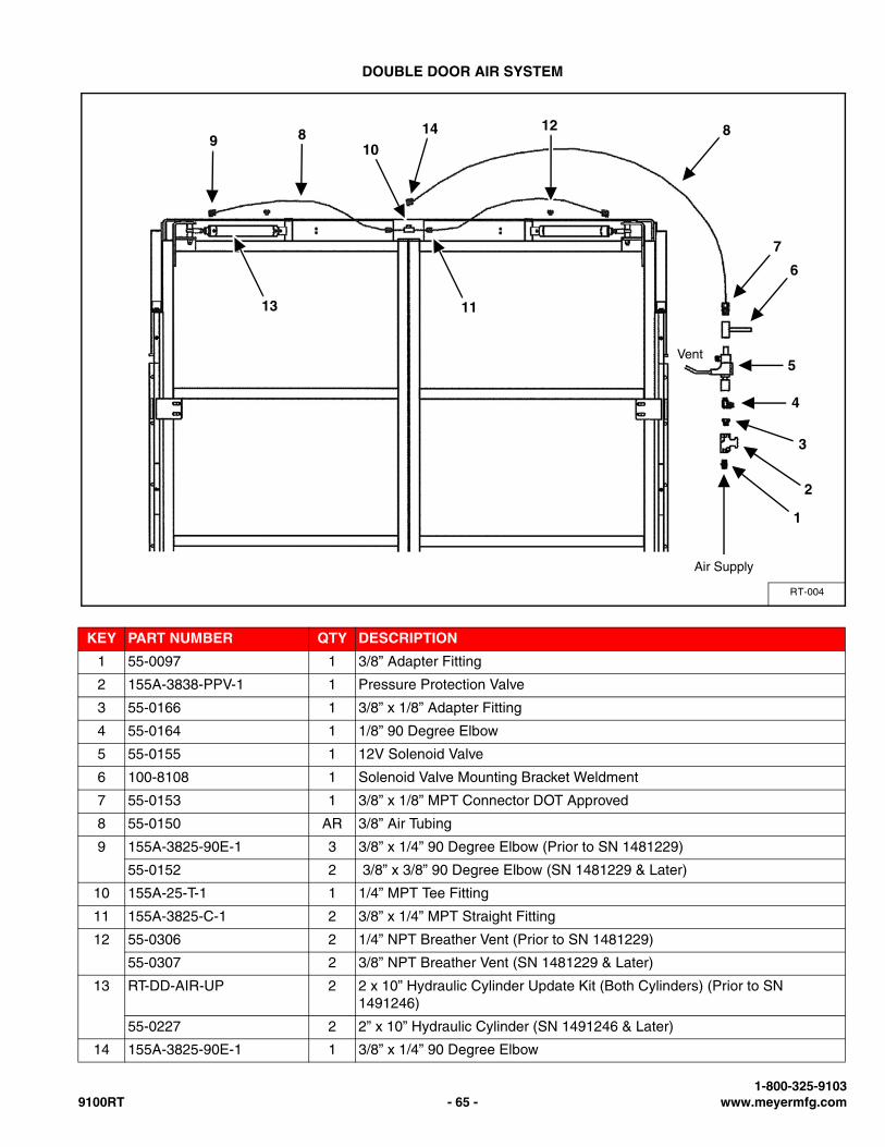
DOUBLE DOOR AIR SYSTEM
KEY PART NUMBER QTY DESCRIPTION
1 55-0097 1 3/8” Adapter Fitting
2 155A-3838-PPV-1 1 Pressure Protection Valve
3 55-0166 1 3/8” x 1/8” Adapter Fitting
4 55-0164 1 1/8” 90 Degree Elbow
5 55-0155 1 12V Solenoid Valve
6 100-8108 1 Solenoid Valve Mounting Bracket Weldment
7 55-0153 1 3/8” x 1/8” MPT Connector DOT Approved
8 55-0150 AR 3/8” Air Tubing
9 155A-3825-90E-1 3 3/8” x 1/4” 90 Degree Elbow (Prior to SN 1481229)
55-0152 2 3/8” x 3/8” 90 Degree Elbow (SN 1481229 & Later)
10 155A-25-T-1 1 1/4” MPT Tee Fitting
11 155A-3825-C-1 2 3/8” x 1/4” MPT Straight Fitting
12 55-0306 2 1/4” NPT Breather Vent (Prior to SN 1481229)
55-0307 2 3/8” NPT Breather Vent (SN 1481229 & Later)
13 RT-DD-AIR-UP 2 2 x 10” Hydraulic Cylinder Update Kit (Both Cylinders) (Prior to SN 1491246)
55-0227 2 2” x 10” Hydraulic Cylinder (SN 1491246 & Later)
14 155A-3825-90E-1 1 3/8” x 1/4” 90 Degree Elbow
RT-004
1
Air Supply
2
3
4
5
6
7
Vent
812
10
1113
8914
1-800-325-91039100RT - 65 - www.meyermfg.com
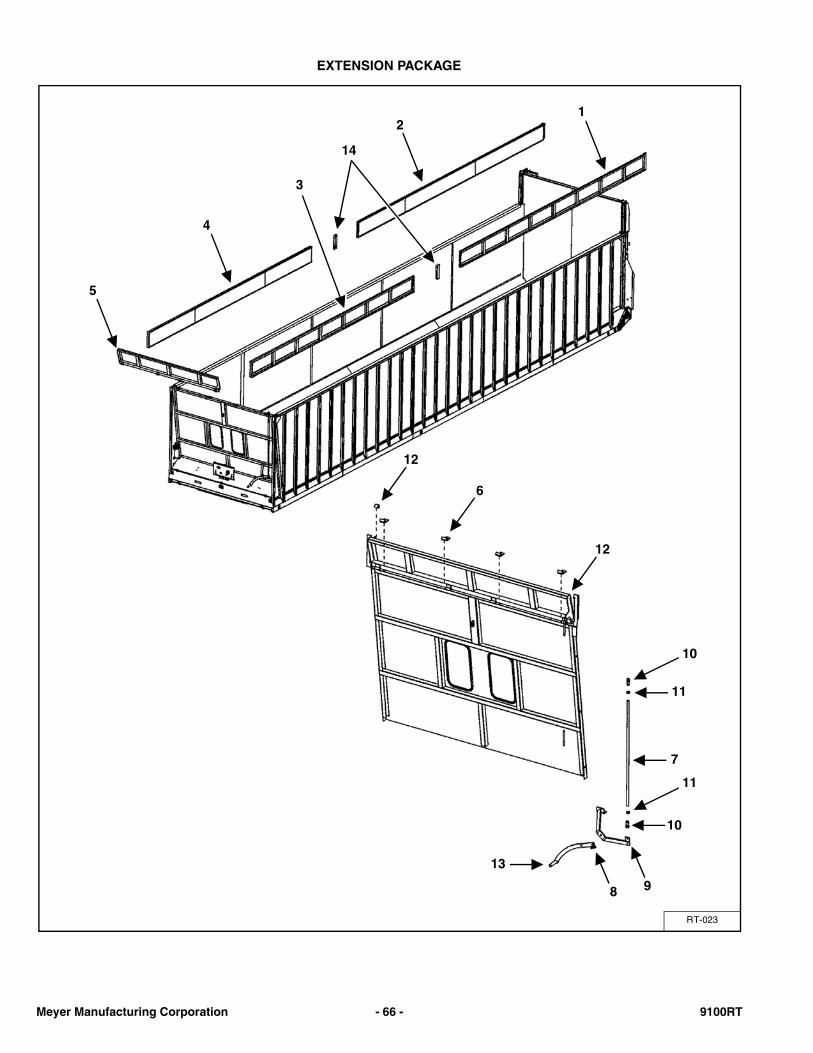
EXTENSION PACKAGE
RT-023
1
6
2
4
5
3
7
8 9
13
12
11
10
12
10
11
14
Meyer Manufacturing Corporation - 66 - 9100RT
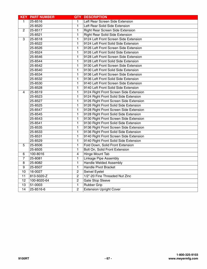
KEY PART NUMBER QTY DESCRIPTION1 25-8516 1 Left Rear Screen Side Extension
25-8520 1 Left Rear Solid Side Extension2 25-8517 1 Right Rear Screen Side Extension
25-8521 1 Right Rear Solid Side Extension3 25-8518 1 9124 Left Front Screen Side Extension
25-8522 1 9124 Left Front Solid Side Extension25-8526 1 9126 Left Front Screen Side Extension25-8524 1 9126 Left Front Solid Side Extension25-8546 1 9128 Left Front Screen Side Extension25-8544 1 9128 Left Front Solid Side Extension25-8542 1 9130 Left Front Screen Side Extension25-8540 1 9130 Left Front Solid Side Extension25-8534 1 9136 Left Front Screen Side Extension25-8532 1 9136 Left Front Solid Side Extension25-8530 1 9140 Left Front Screen Side Extension25-8528 1 9140 Left Front Solid Side Extension
4 25-8519 1 9124 Right Front Screen Side Extension25-8523 1 9124 Right Front Solid Side Extension25-8527 1 9126 Right Front Screen Side Extension25-8525 1 9126 Right Front Solid Side Extension25-8547 1 9128 Right Front Screen Side Extension25-8545 1 9128 Right Front Solid Side Extension25-8543 1 9130 Right Front Screen Side Extension25-8541 1 9130 Right Front Solid Side Extension25-8535 1 9136 Right Front Screen Side Extension25-8533 1 9136 Right Front Solid Side Extension25-8531 1 9140 Right Front Screen Side Extension25-8529 1 9140 Right Front Solid Side Extension
5 25-8506 1 Fold Down, Solid Front Extension25-8505 1 Bolt On, Solid Front Extension
6 100-8016 4 Hinge Mount Tab7 25-8081 1 Linkage Pipe Assembly8 25-8082 1 Handle Welded Assembly9 25-8507 1 Handle Pivot Bracket
10 16-0027 2 Swivel Eyelet11 813-5020-Z 2 1/2”-20 Fine Threaded Nut Zinc12 100-8020-64 2 Gate Stop Sleeve13 51-0003 1 Rubber Grip14 25-8516-6 2 Extension Upright Cover
1-800-325-91039100RT - 67 - www.meyermfg.com
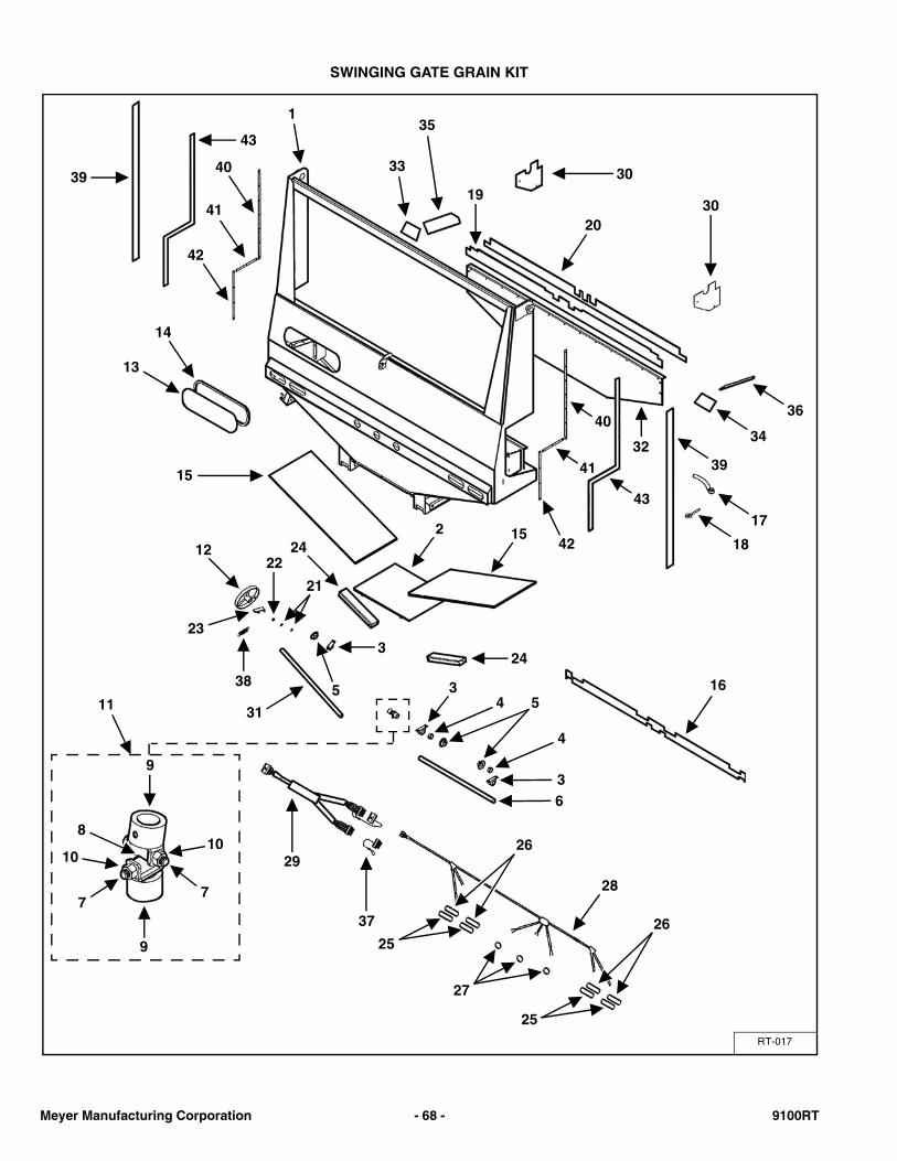
SWINGING GATE GRAIN KIT
RT-017
1
30
3020
19
33
3543
3940
41
42
14
13
15
22412
23
22
38
21
5
324
15
16
42
41
40
32
43
18
17
39
34
36
31
3
4
5
63
411
9
8
10
7
10
7
9
29
37
25
26
27
28
25
26
Meyer Manufacturing Corporation - 68 - 9100RT
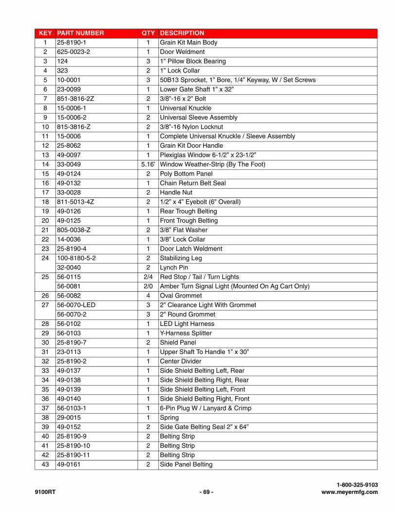
KEY PART NUMBER QTY DESCRIPTION1 25-8190-1 1 Grain Kit Main Body
2 625-0023-2 1 Door Weldment
3 124 3 1” Pillow Block Bearing
4 323 2 1” Lock Collar
5 10-0001 3 50B13 Sprocket, 1” Bore, 1/4” Keyway, W / Set Screws
6 23-0099 1 Lower Gate Shaft 1” x 32”
7 851-3816-2Z 2 3/8”-16 x 2” Bolt
8 15-0006-1 1 Universal Knuckle
9 15-0006-2 2 Universal Sleeve Assembly
10 815-3816-Z 2 3/8”-16 Nylon Locknut
11 15-0006 1 Complete Universal Knuckle / Sleeve Assembly
12 25-8062 1 Grain Kit Door Handle
13 49-0097 1 Plexiglas Window 6-1/2” x 23-1/2”
14 33-0049 5.16’ Window Weather-Strip (By The Foot)
15 49-0124 2 Poly Bottom Panel
16 49-0132 1 Chain Return Belt Seal
17 33-0028 2 Handle Nut
18 811-5013-4Z 2 1/2” x 4” Eyebolt (6” Overall)
19 49-0126 1 Rear Trough Belting
20 49-0125 1 Front Trough Belting
21 805-0038-Z 2 3/8” Flat Washer
22 14-0036 1 3/8” Lock Collar
23 25-8190-4 1 Door Latch Weldment
24 100-8180-5-2 2 Stabilizing Leg
32-0040 2 Lynch Pin
25 56-0115 2/4 Red Stop / Tail / Turn Lights
56-0081 2/0 Amber Turn Signal Light (Mounted On Ag Cart Only)
26 56-0082 4 Oval Grommet
27 56-0070-LED 3 2” Clearance Light With Grommet
56-0070-2 3 2” Round Grommet
28 56-0102 1 LED Light Harness
29 56-0103 1 Y-Harness Splitter
30 25-8190-7 2 Shield Panel
31 23-0113 1 Upper Shaft To Handle 1” x 30”
32 25-8190-2 1 Center Divider
33 49-0137 1 Side Shield Belting Left, Rear
34 49-0138 1 Side Shield Belting Right, Rear
35 49-0139 1 Side Shield Belting Left, Front
36 49-0140 1 Side Shield Belting Right, Front
37 56-0103-1 1 6-Pin Plug W / Lanyard & Crimp
38 29-0015 1 Spring
39 49-0152 2 Side Gate Belting Seal 2” x 64”
40 25-8190-9 2 Belting Strip
41 25-8190-10 2 Belting Strip
42 25-8190-11 2 Belting Strip
43 49-0161 2 Side Panel Belting
1-800-325-91039100RT - 69 - www.meyermfg.com
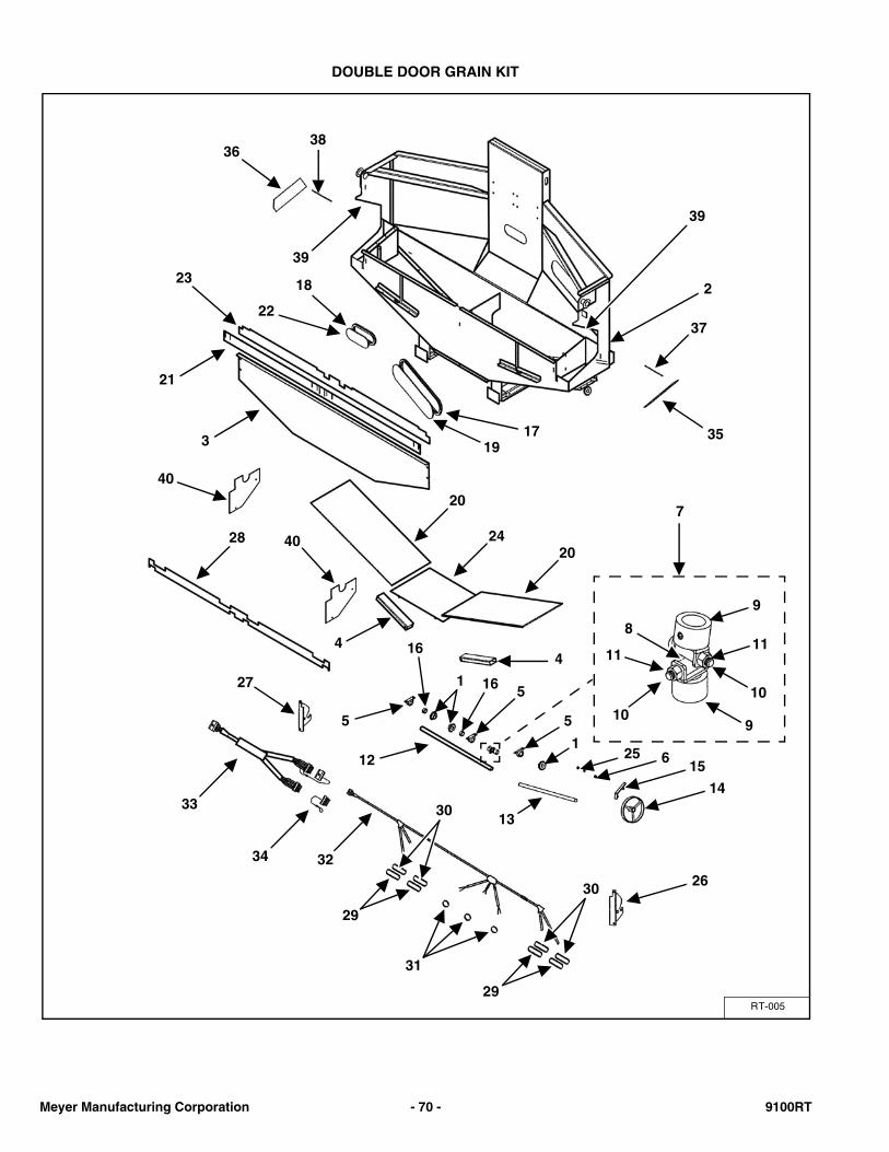
DOUBLE DOOR GRAIN KIT
RT-005
3638
39
39
37
35
218
22
23
21
1917
3
20
2420
28
44
7
5
16
1 16 5
12
5
125 6
14
13
15
8
11
10
9
11
109
27
33
34 32
31
30
29
29
30
26
40
40
Meyer Manufacturing Corporation - 70 - 9100RT
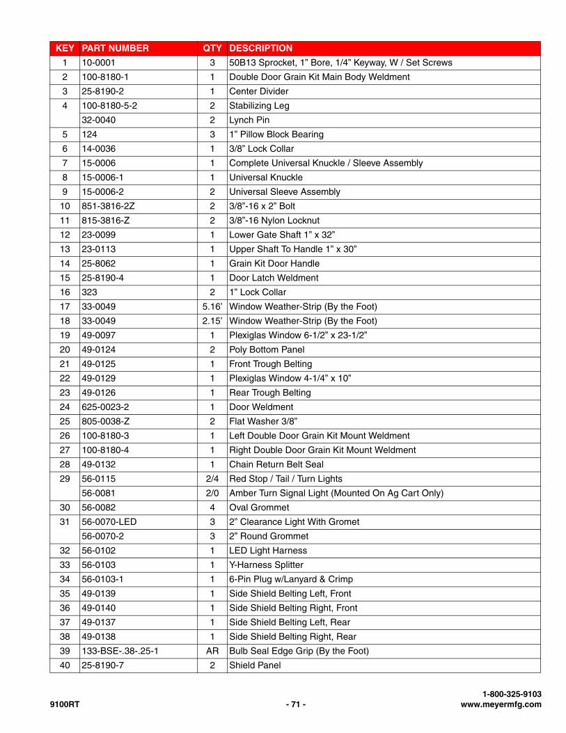
KEY PART NUMBER QTY DESCRIPTION
1 10-0001 3 50B13 Sprocket, 1” Bore, 1/4” Keyway, W / Set Screws
2 100-8180-1 1 Double Door Grain Kit Main Body Weldment
3 25-8190-2 1 Center Divider
4 100-8180-5-2 2 Stabilizing Leg
32-0040 2 Lynch Pin
5 124 3 1” Pillow Block Bearing
6 14-0036 1 3/8” Lock Collar
7 15-0006 1 Complete Universal Knuckle / Sleeve Assembly
8 15-0006-1 1 Universal Knuckle
9 15-0006-2 2 Universal Sleeve Assembly
10 851-3816-2Z 2 3/8”-16 x 2” Bolt
11 815-3816-Z 2 3/8”-16 Nylon Locknut
12 23-0099 1 Lower Gate Shaft 1” x 32”
13 23-0113 1 Upper Shaft To Handle 1” x 30”
14 25-8062 1 Grain Kit Door Handle
15 25-8190-4 1 Door Latch Weldment
16 323 2 1” Lock Collar
17 33-0049 5.16’ Window Weather-Strip (By the Foot)
18 33-0049 2.15’ Window Weather-Strip (By the Foot)
19 49-0097 1 Plexiglas Window 6-1/2” x 23-1/2”
20 49-0124 2 Poly Bottom Panel
21 49-0125 1 Front Trough Belting
22 49-0129 1 Plexiglas Window 4-1/4” x 10”
23 49-0126 1 Rear Trough Belting
24 625-0023-2 1 Door Weldment
25 805-0038-Z 2 Flat Washer 3/8”
26 100-8180-3 1 Left Double Door Grain Kit Mount Weldment
27 100-8180-4 1 Right Double Door Grain Kit Mount Weldment
28 49-0132 1 Chain Return Belt Seal
29 56-0115 2/4 Red Stop / Tail / Turn Lights
56-0081 2/0 Amber Turn Signal Light (Mounted On Ag Cart Only)
30 56-0082 4 Oval Grommet
31 56-0070-LED 3 2” Clearance Light With Gromet
56-0070-2 3 2” Round Grommet
32 56-0102 1 LED Light Harness
33 56-0103 1 Y-Harness Splitter
34 56-0103-1 1 6-Pin Plug w/Lanyard & Crimp
35 49-0139 1 Side Shield Belting Left, Front
36 49-0140 1 Side Shield Belting Right, Front
37 49-0137 1 Side Shield Belting Left, Rear
38 49-0138 1 Side Shield Belting Right, Rear
39 133-BSE-.38-.25-1 AR Bulb Seal Edge Grip (By the Foot)
40 25-8190-7 2 Shield Panel
1-800-325-91039100RT - 71 - www.meyermfg.com
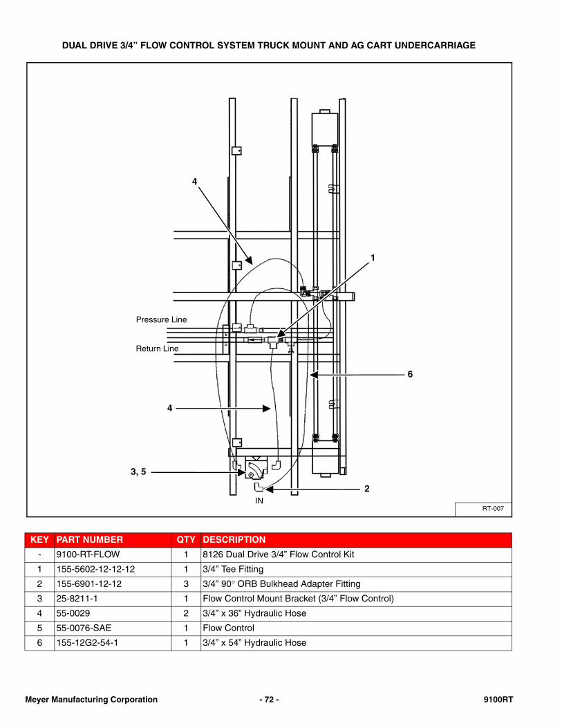
DUAL DRIVE 3/4” FLOW CONTROL SYSTEM TRUCK MOUNT AND AG CART UNDERCARRIAGE
KEY PART NUMBER QTY DESCRIPTION
- 9100-RT-FLOW 1 8126 Dual Drive 3/4” Flow Control Kit
1 155-5602-12-12-12 1 3/4” Tee Fitting
2 155-6901-12-12 3 3/4” 90° ORB Bulkhead Adapter Fitting
3 25-8211-1 1 Flow Control Mount Bracket (3/4” Flow Control)
4 55-0029 2 3/4” x 36” Hydraulic Hose
5 55-0076-SAE 1 Flow Control
6 155-12G2-54-1 1 3/4” x 54” Hydraulic Hose
RT-007
1
Pressure Line
Return Line
4
6
4
3, 5
2IN
Meyer Manufacturing Corporation - 72 - 9100RT

DUAL DRIVE 1” FLOW CONTROL SYSTEM 5TH WHEEL AG TRAILER
KEY PART NUMBER QTY DESCRIPTION
1 100-8126-27 1 Flow Control Mount Bracket (1” Flow Control)
2 155-16EFG4K-41.5-1 1 1” x 41.5” Hydraulic Hose
3 155-16100R16-97-1 1 1” x 97” Hydraulic Hose
4 955-0154-L 1 1” 90° Elbow JIC To O-Ring, Long
5 155-6801-16 2 1” 90° Elbow JIC To O-Ring
6 155-FC51-16SAE 1 1” Flow Control
7 810-3816-Z 2 3/8” Spin Lock Nut
8 815-3118-Z 4 5/16” Nylon Lock Nut
9 851-3118-3.75Z 4 5/16” x 3-3/4” Bolt
10 851-3816-1Z 2 3/8” x 1” Bolt
RT-036A
3
5
2
1, 6, 7, 8, 9, 10
4
RETURN
PRESSURE
Return Gate Delay
Pressure Gate Delay
1-800-325-91039100RT - 73 - www.meyermfg.com
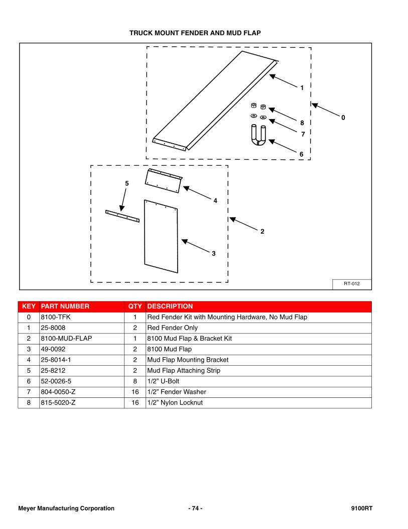
TRUCK MOUNT FENDER AND MUD FLAP
KEY PART NUMBER QTY DESCRIPTION
0 8100-TFK 1 Red Fender Kit with Mounting Hardware, No Mud Flap
1 25-8008 2 Red Fender Only
2 8100-MUD-FLAP 1 8100 Mud Flap & Bracket Kit
3 49-0092 2 8100 Mud Flap
4 25-8014-1 2 Mud Flap Mounting Bracket
5 25-8212 2 Mud Flap Attaching Strip
6 52-0026-5 8 1/2” U-Bolt
7 804-0050-Z 16 1/2” Fender Washer
8 815-5020-Z 16 1/2” Nylon Locknut
RT-012
1
8
7
6
4
2
3
5
0
Meyer Manufacturing Corporation - 74 - 9100RT
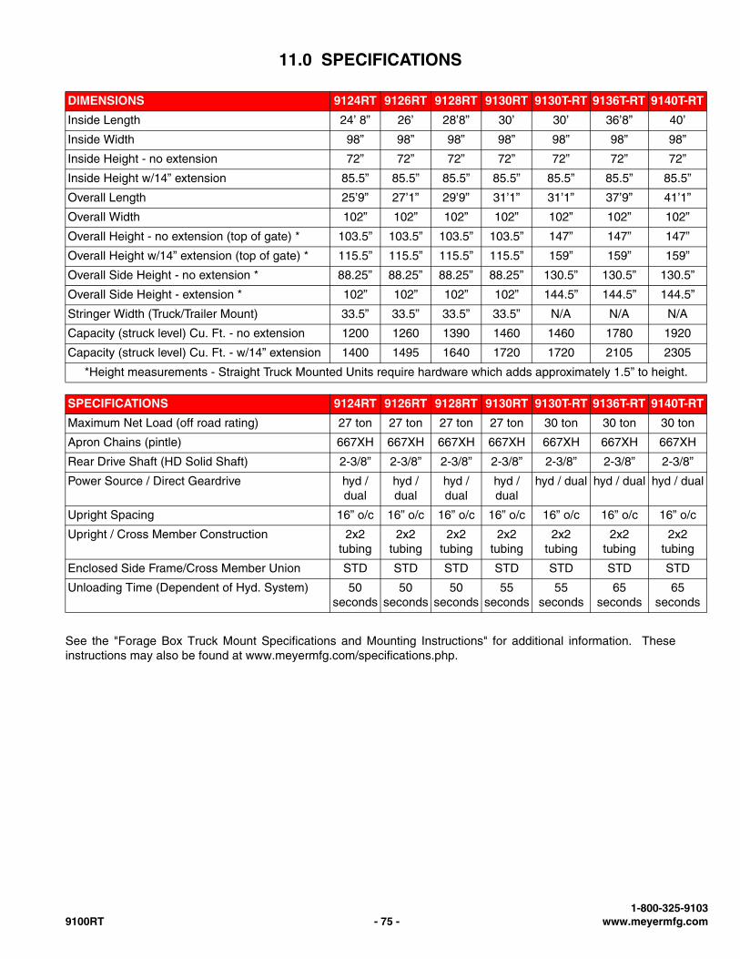
11.0 SPECIFICATIONS
See the "Forage Box Truck Mount Specifications and Mounting Instructions" for additional information. Theseinstructions may also be found at www.meyermfg.com/specifications.php.
DIMENSIONS 9124RT 9126RT 9128RT 9130RT 9130T-RT 9136T-RT 9140T-RT
Inside Length 24’ 8” 26’ 28’8” 30’ 30’ 36’8” 40’
Inside Width 98” 98” 98” 98” 98” 98” 98”
Inside Height - no extension 72” 72” 72” 72” 72” 72” 72”
Inside Height w/14” extension 85.5” 85.5” 85.5” 85.5” 85.5” 85.5” 85.5”
Overall Length 25’9” 27’1” 29’9” 31’1” 31’1” 37’9” 41’1”
Overall Width 102” 102” 102” 102” 102” 102” 102”
Overall Height - no extension (top of gate) * 103.5” 103.5” 103.5” 103.5” 147” 147” 147”
Overall Height w/14” extension (top of gate) * 115.5” 115.5” 115.5” 115.5” 159” 159” 159”
Overall Side Height - no extension * 88.25” 88.25” 88.25” 88.25” 130.5” 130.5” 130.5”
Overall Side Height - extension * 102” 102” 102” 102” 144.5” 144.5” 144.5”
Stringer Width (Truck/Trailer Mount) 33.5” 33.5” 33.5” 33.5” N/A N/A N/A
Capacity (struck level) Cu. Ft. - no extension 1200 1260 1390 1460 1460 1780 1920
Capacity (struck level) Cu. Ft. - w/14” extension 1400 1495 1640 1720 1720 2105 2305
*Height measurements - Straight Truck Mounted Units require hardware which adds approximately 1.5” to height.
SPECIFICATIONS 9124RT 9126RT 9128RT 9130RT 9130T-RT 9136T-RT 9140T-RT
Maximum Net Load (off road rating) 27 ton 27 ton 27 ton 27 ton 30 ton 30 ton 30 ton
Apron Chains (pintle) 667XH 667XH 667XH 667XH 667XH 667XH 667XH
Rear Drive Shaft (HD Solid Shaft) 2-3/8” 2-3/8” 2-3/8” 2-3/8” 2-3/8” 2-3/8” 2-3/8”
Power Source / Direct Geardrive hyd / dual
hyd / dual
hyd / dual
hyd / dual
hyd / dual hyd / dual hyd / dual
Upright Spacing 16” o/c 16” o/c 16” o/c 16” o/c 16” o/c 16” o/c 16” o/c
Upright / Cross Member Construction 2x2 tubing
2x2 tubing
2x2 tubing
2x2 tubing
2x2 tubing
2x2 tubing
2x2 tubing
Enclosed Side Frame/Cross Member Union STD STD STD STD STD STD STD
Unloading Time (Dependent of Hyd. System) 50 seconds
50 seconds
50 seconds
55 seconds
55 seconds
65 seconds
65 seconds
1-800-325-91039100RT - 75 - www.meyermfg.com
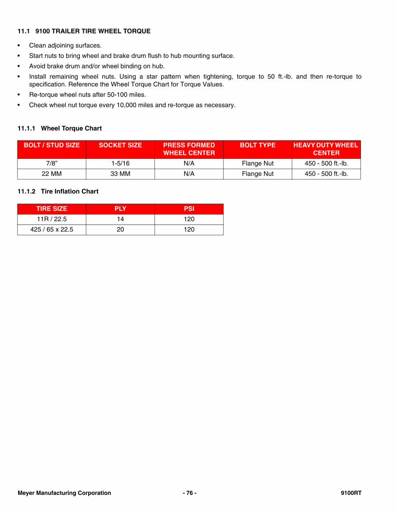
11.1 9100 TRAILER TIRE WHEEL TORQUE
• Clean adjoining surfaces.
• Start nuts to bring wheel and brake drum flush to hub mounting surface.
• Avoid brake drum and/or wheel binding on hub.
• Install remaining wheel nuts. Using a star pattern when tightening, torque to 50 ft.-lb. and then re-torque tospecification. Reference the Wheel Torque Chart for Torque Values.
• Re-torque wheel nuts after 50-100 miles.
• Check wheel nut torque every 10,000 miles and re-torque as necessary.
11.1.1 Wheel Torque Chart
11.1.2 Tire Inflation Chart
BOLT / STUD SIZE SOCKET SIZE PRESS FORMED WHEEL CENTER
BOLT TYPE HEAVY DUTY WHEEL CENTER
7/8” 1-5/16 N/A Flange Nut 450 - 500 ft.-lb.
22 MM 33 MM N/A Flange Nut 450 - 500 ft.-lb.
TIRE SIZE PLY PSI
11R / 22.5 14 120
425 / 65 x 22.5 20 120
Meyer Manufacturing Corporation - 76 - 9100RT

NOTES

NOTES
MAINTENANCE RECORD
MODEL NO. ____________________________________ SERIAL NO. ____________________________________
DATE SERVICE PERFORMED DATE SERVICE PERFORMED
Manufactured by:
Meyer Manufacturing Corporation674 W. Business Cty Rd A
Dorchester, WI 54425Phone: 1-800-325-9103
Fax: 715-654-5513Email: [email protected]: www.meyermfg.com

Meyer Manufacturing Corporation674 W. Business Cty Rd A
Dorchester, WI 54425Phone: 1-800-325-9103
Fax: 715-654-5513Email: [email protected]: www.meyermfg.com