.90M/1.0M/1.2M Offset Antenna Receive only and Transmit ...
16
INSTALLATION & ASSEMBLY INSTRUCTIONS .90M/1.0M/1.2M Offset Antenna Receive only and Transmit-Receive ANTENNA SYSTEMS
Transcript of .90M/1.0M/1.2M Offset Antenna Receive only and Transmit ...

INSTALLATION &ASSEMBLY INSTRUCTIONS
.90M/1.0M/1.2M Offset AntennaReceive only andTransmit-Receive
ANTENNA SYSTEMS
2
This PATRIOT ANTENNA equipment is warranted to be free from defects in material and workmanship under normaluse and service. PATRIOT ANTENNA shall repair or replace defective equipment, at no charge, or at its option, refundthe purchase price, if the equipment is returned to PATRIOT ANTENNA not more than twelve (12) months aftershipment. Removal or reinstallation of equipment and its transportation shall not be at cost of PATRIOT ANTENNAexcept PATRIOT ANTENNA shall return repaired or replaced equipment freight prepaid.
This Warranty shall not apply to equipment which has been repaired or altered in any way so as to affect its stabilityor durability, or which has been subject to misuse, negligence or accident. This Warranty does not cover equipmentwhich has been impaired by severe weather conditions such as excessive wind, ice, storms, lightning, or other naturaloccurrences over which PATRIOT ANTENNA has no control, and this Warranty shall not apply to equipment whichhas been operated or installed other than in accordance with the instructions furnished by PATRIOT ANTENNA.
Claimants under this Warranty shall present their claims along with the defective equipment to PATRIOT ANTENNAimmediately upon failure. Noncompliance with any part of this claim procedure may invalidate this warranty in whole orin part.
THIS WARRANTY IS EXPRESSLY IN LIEU OF ALL OTHER AGREEMENTS AND WARRANTIES, ANY IMPLIEDWARRANTY OF MERCHANTABILITY OR FITNESS FOR A PARTICULAR PURPOSE IS LIMITED IN DURATIONTO THE DURATION OF THIS WARRANTY. PATRIOT ANTENNA DOES NOT AUTHORIZE ANY PERSON TOASSUME FOR IT THE OBLIGATIONS CONTAINED IN THIS WARRANTY AND PATRIOT ANTENNA NEITHERASSUMES NOR AUTHORIZES ANY REPRESENTATIVE OR OTHER PERSON TO ASSUME FOR IT ANY OTHERLIABILITY IN CONNECTION WITH THE EQUIPMENT DELIVERED OR PROVIDED.
IN NO EVENT SHALL PATRIOT ANTENNA BE LIABLE FOR ANY LOSS OF PROFITS, LOSS OF USE, INTERRUP-TION OF BUSINESS, OR INDIRECT, SPECIAL OR CONSEQUENTIAL DAMAGES OF ANY KIND.
In no event shall PATRIOT ANTENNA be liable for damages in an amount greater than the purchase price of theequipment.
Some states do not allow limitations on how long an implied warranty lasts, or allow the exclusion or limitation ofincidental or consequential damages, so the above limitations or exclusions may not apply to you.
PATRIOT ANTENNA has the right to void the warranty when the antenna is installed by someone other then a certifiedinstaller.
LIMITED TWELVE (12) MONTH WARRANTY
Patriot Antenna Systems704 North Clark StreetAlbion, MI 49224 USA Tel: (517)629-5990Fax: (517)629-6690
E-mail: [email protected]
Product Serial Number- _________________Date Purchased- ____________
INSTALLATION OF THIS PRODUCT SHOULD BE PERFORMED ONLY BY A PROFESSIONAL IN-STALLER AND IS NOT RECOMMENDED FOR CONSUMER D.I.Y. (DO-IT-YOURSELF) INSTALLATIONS.
WATCH FOR WIRES! Installation of this product near power lines is dangerous. For yourown safety, follow these important safety rules.
1. Perform as many functions as possible on the ground.
2. Watch out for overhead power lines. Check the distance to the power lines before startinginstallation. We recommend you stay a minimum of 6 meters (20 feet) from all power lines.
3. Do not use metal ladders.
4. Do not install antenna or mast assembly on a windy day.
5. If you start to drop antenna or mast assembly, get away from it and let if fall.
6. If any part of the antenna or mast assembly comes in contact with a power line, call your local power company. DO NOT TRY TO REMOVE IT YOURSELF! They will remove itsafely.
7. Make sure that the mast assembly is properly grounded.
Assembling dish antennas on windy days can be dangerous. Because of the antenna sur-face, even slight winds create strong forces. For example, a 1.0m antenna facing a wind of32 km/h (20 mph) can undergo forces of 269 N (60 lbs.). Be prepared to safely handle theseforces at unexpected moments. Do not attempt to assemble, move or mount dish on windydays or serious, even fatal accidents may occur. PATRIOT ANTENNA SYSTEMS is not re-sponsible or liable for damage or injury resulting from antenna installations.
Antennas improperly installed or installed to an inadequate structure are very susceptibleto wind damage. This damage can be very serious or even life threatening. The owner andinstaller assumes full responsibility that the installation is structurally sound to support allloads (weight, wind & ice) and properly sealed against leaks. PATRIOT ANTENNA SYSTEMSwill not accept liability for any damage caused by a satellite system due to the many un-known variable applications.
IMPORTANT!!!
DANGER!!!
WARNING!!!
WARNING!!!
3

INTRODUCTION
UNPACKING AND INSPECTIONShipping cartons should be unpacked and contents checked for damaged or missing parts. Shouldthere be any parts that are damaged or missing, please contact technical support for replacement.
Thank you for purchasing your Patriot Commercial Antenna. We trust that you will find this to be awell designed product that will provide many years of reliable service. This manual covers theassembly and installation of the .90m/1.0m/1.2m Antenna System. Read this manual thoroughlybefore beginning assembly. For best results in the assembly process. Perform each step in thesame sequence as listed in this manual. Record the serial number of the unit on to page 2 forfuture reference and read the warranty information. The serial number can be found on the antennaback structure.
SITE SELECTION
The main objective of conducting a site survey utilizing a compass and inclinometer is to choosea mounting location on the ground that will give you the greatest amount of swing for azimuth andelevation for present as well as future use. A thorough preinstallation site survey is strongly rec-ommended because it can alert you to any “look angle”, soil, wind or other problems.
The first and most important consideration when choosing a prospective antenna site is whetheror not the area can provide an acceptable “look angle” to the satellite. A site with a clear, unob-structed view facing south, southeast is required. Your antenna site must be selected in advanceso that you will be able to receive the strongest signal available. Also consider obstructions thatmay occur in the future such as the growth of trees.
It is important to conduct an on-site survey with a portable antenna or with a compass and clinom-eter to avoid interference, obstructions, etc.
When selecting “look angle”, be sure to observe and take readings approximately 10 deg to the leftand right, above and below your selected “look angle”.
Before Ground Pole Installation, the soil type should be checked because soil conditions varywidely in composition and load bearing capacity. A soil check will help you to determine the typeand size of foundation required to provide a stable base for the antenna.
Before digging is done, information regarding the possibility of underground telephone lines, powerlines, storm drains, etc., in the excavation area should be obtained from the appropriate agency.
As with any other type of construction, a local building permit may be required before installing anantenna. It is the property owner’s responsibility to obtain any and all permits. Ground mounts arecertified for 125 mph wind survival.
4

5
Parts and Hardware
1
2
3
4
5
6
7
8
9
10
10
11
12
13
13
13 14
14
15
15
15
15
15
15
16
17
1718
19
19
20
21
22
23
23
24
25
26
27
28
29
3031
32
33
34
ITEM QTY.PART NO. DESCRIPTION12345678910111213141516171819202122232425262728293031
1121121112114327
1548113551111111
210081210080
210082HWD Prebag H1101HWD Prebag H1101HWD Prebag H1101
TX-FDOMTKULTXFD-DPLCOPOL/TXFD-KULTXFD-OMTKALTXFD- OMTPLKA
Reflector, .90m,1.0m, or 1.2mBack Plate Tx OffsetBracket Elevation Adaptor
Bracket AzimuthBracket, 3” Pipe
Upper Clevis, ElevationLower Clevis, ElevationPlastic Plugs1/2-20 Thread Elevation Rod 13”Adjusting Nut 1/2” Thread 2” Long1/2” SAE Flat Washer1/2 - 20 Fin Hex Nut3/8” SAE Flat Washer5/16” Lock Washer3/8 - NYL INST L/N3/8 - 16 x 1 1/2 Carr. Bolt, G-2
Fine Az Adjusting Bolt (Pre-Assembled)
1/4 - 20 Fin Hex Nut
Feed Holder BottomKu Rx Only, Feed Assembly (Optional)Ku Tx/Rx XPol, Feed Assembly (Optional)Ku Tx/Rx CoPol, Feed Assembly (Optional)Ka Tx/Rx Linear Pol, Feed Assembly (Optional)Ka Tx/Rx Circular Pol, Feed Assembly (Optional)
5/16-18 x 5/8” HCS G-2
HWD Prebag H1101HWD Prebag H1101HWD Prebag H1101
HWD Prebag H1101HWD Prebag H1101HWD Prebag H1101HWD Prebag H1101
HWD Prebag H1101HWD Prebag H1101
PEO400BTXFD-KA/KUR
1R2092810
1RSP02740(2 7/8”)1RSP03040(3”) Mast Pipe, 2 7/8” or 3” O.D. (not included)210083
20982Ku Feed Support, .90m, 1.0m, or 1.2m
HWD Prebag H1101 3/8 - 16 x 2 HCS, G-2 (Pre-assembled) HWD Prebag H1101 3/8 - 16 x 3 HCS, G-2
1/4 - 20 x 1 SOC Cap SC
PEO400A Feed Holder Top
209(.90m)210(1.0M) 212(1.2M)001
HWD Prebag H1101 4
323334
5-16/18 Bolt5-16/18 Lockwasher5-16/18 Nut
5-16/18 Bolt5-16/18 Lockwasher5-16/18 Nut
444
209(.90M)210(1.0M) 212(1.2M)003

Preinstallation materials checklist
g y
Grounding Rod Clamp & Grounding Block - As required byNational Electric Code or local codes.
Ground Wire - #10 solid copper or as required by NationalElectric Code or local codes.
Coaxial Cable (Size & Length required).
Concrete - (See Ground Pole section below).
#3 Rebar - (See Ground Pole section below). Deformedsteel per ASTM A615, grade 40 or 60.
-Universal mount/wall mount #CHA-WR300 not shown.
Assembly tools required
1- 1/4” allen wrench (supplied)1- 5/32” allen wrench2- Combination wrench -3/4”2- Combination wrenches - 9/16”2- Combination wrenches - 1/2”2- Combination wrenches - 7/16”1- 9/16 ratcheting wrench for Fine Az-El Adjustment1- Inclinometer (for sighting in)1- Compass (for sighting in)
• Steel Mast: L=72”; 2-7/8” (73mm) or 3”(76mm)O.D. Tubing Plumb within 1deg.• Concrete: 3000 psi at 28 days, poured against undisturbed soil (Allow concrete 24 hour set time before installation of antenna)• Soil Bearing Capacity > 2000 psf.• Ground the Antenna to meet applicable local Codes.
In-Ground Mast Foundation
6
Mast Pipe2-7/8” or 3” O.D.
Anti-Twist Rebar5/8” Diam. x 9”
60
24 18

7
Non-Penetrating Mount (optional)
1. Assemble the Non-Penetrating mount per the supplied instructions to provide the mast forthe mount installation.
2. Refer to the ballast chart for the required ballast to be placed in the Non-Pen Ballast Trays.
NOTE: Higher elevation angles can use less ballast. If there are any possible future elevationadjustments that could result in a lower elevation angle use the 22 deg elevation angle fromthe chart for the ballast requirement!
Add-on Dual Tray(if necessary)
28 lb
9 blocks per tray
4x8x16 Block
Elevation(deg)
80 100 125
22 259 480 826
40 202 374 644
60 116 216 372
100cm Ballast Chart
Ballast Required (lbs)W ind Speed (m ph)
Elevation(deg)
80 100 125
22 411 733 1236
40 321 572 964
60 185 330 556
120cm Ballast Chart
Ballast Required (lbs)W ind Speed (m ph)
(use single tray PTX-NP 300S)
(must use dual tray PTX-NP300D)
Elevation(deg)
80 100 125
22 207 391 679
40 162 305 529
60 93 176 305
90cm Ballast Chart
Ballast Required (lbs)W ind Speed (m ph)
(use single tray PTX-NP300S)

* S
PE
CIA
L W
IND
RE
GIO
NS
:R
ecor
ds o
r ex
perie
nce
indi
cate
s th
at t
he w
ind
spee
ds a
re h
ighe
r in
mou
ntai
nous
ter
rain
, go
rges
, an
d oc
ean
prom
onto
ries
and
shal
l be
exam
ined
for
unus
ual w
ind
cond
ition
s. C
onta
ct y
our
loca
l met
eoro
logi
cal a
utho
rity
and
a lo
cal c
ivil
or p
rofe
ssio
nal e
ngin
eer
if yo
ur in
stal
latio
n is
in o
ne o
fth
ese
area
s.
8

9
Az-El Mount Assembly
1. Using the hardware illustrated, as-semble the Pipe brackets, Azimuthbracket, and Clevis bracket as shown.
AzimuthBracket
PipeBracket
Clevis
1x
11x
18x
5x 4x
1x
A
B
CD
E
F
A
AA
A
A
B
B
C
D
D
D
D
D
D
D
DD
D
E
E
E
E
E
EE
E
E
E
E
EE
F
(Place Az/El mount after assembly on toground pole or NPRmmount.)

FeedSupportTube
10
Mount Assembly Continued
2. Attach the Elevation Brackets (2) to the Feed Support Tube and the Azimuth Bracket asshown. Partially tighten all this hardware at this time.
3. Assemble the Elevation rod with nuts and washers as shown.
AzimuthBracket
ElevationBracket
FeedSupportTube
Az-El MountAssembly 4x
4x
5x
10x
2x
3x
A
B
C
D
E
F
A
B
CD
E
F
NOTE: Ka band Antenna’s ,Take extra care in assembly and handling - Do Not Stack!.
Faces should be flush
ElevationBracket
Top View
ElevationRod

g
11
Reflector Assembly1. Assemble Back Plate to Antenna using (4) 5/16x1 bolts,lockwashers, and nuts.2. Attach the Antenna Assembly to the Elevation Brackets using the illustrated hardware.3. Tighten the Antenna Assembly Hardware, then tighten the Elevation Bracket hardware.
4x
4x
4x
ElevationBracketHardware
Antenna assyHardware
Antennaassy
5/16 Hardware
BackPlate
NOTE:Make sure that back plate is NOT installedupside down. Install as shown
INSTALL BACK PLATTER WITH THIS NOTCH DOWN

12
3. Insert plastic plug into end of feed support tube.
Feed Assembly1. Attach the relevant Feed Assembly.2. Insert the Feed Assembly into the Feed holder and assemble to the Feed Support Tubeusing the hardware illustrated below.NOTE: 2 nuts slide into the back of the Feed Holder.
5x
5x
Refer to page 5 for moreinformation of Feed Assemblies.
Rx Port
Rx Port
Rx Port
Rx Port
Rx Port
Tx Port
Tx Port
Tx Port
Tx Port
Feed Horn
FeedHolder
FeedSupportTube
TxPort
RxPort
Plug
27
28
29
30
31
Ku Band Rx
Ku Band Tx/Rx
Ku-Band Co-Pol Tx/Rx
KA-BandLinear Tx/Rx
KA-BandCircular Tx/Rx
13
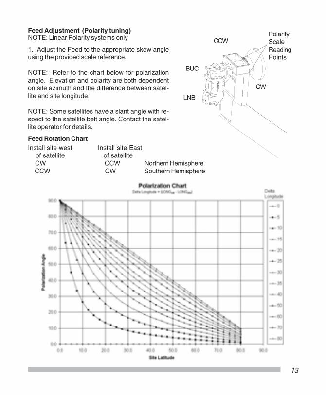
Feed Adjustment (Polarity tuning)
1. Adjust the Feed to the appropriate skew angleusing the provided scale reference.
NOTE: Refer to the chart below for polarizationangle. Elevation and polarity are both dependenton site azimuth and the difference between satel-lite and site longitude.
NOTE: Some satellites have a slant angle with re-spect to the satellite belt angle. Contact the satel-lite operator for details.
CW
CCW
Install site west Install site East of satellite of satellite CW CCW Northern Hemisphere CCW CW Southern Hemisphere
Feed Rotation Chart
LNB
BUC
PolarityScaleReadingPoints
NOTE: Linear Polarity systems only
14
Antenna PointingNOTE: The Reflector contains a 22 degree offset look angle for the 1.0/1.2 and 21 degree angle for the.90m. Therefore, when the reflector aperture is perpendicular to the ground, the antenna is actuallylooking 22 degrees, or 21 degrees for the .90, in elevation. All mount hardware should be firm, but nottight..1. Adjust the reflector up or down in elevation by turning the two 1/2” hex nuts at the Clevis until thedesired elevation is measured (taking reading from the face of the reflector).
Elevation of Satellite above horizon = Measured angle from face of reflector minus 22 or 21 respectfully.
2. Azimuth Adjustment: With the electronics set to acquire the satellite, rotate the antenna in azimuth untilthe satellite is found. Roughly obtain the strongest signal and tighten the hardware on the Pipe Brackets.
5. Patriot recommends the use of cross pol nulling using a spectrum analyzer during TX/RX installations.After tightening the azimuth and elevation hardware, peak the co-pol signal using the spectrum analyzer.Then rotate the feed assemble roughly 90 degrees to obtain a cross pol null. Fine tune the null. The scaleon the feed horn can be used with the tick mark on feed holder top or the seam between feed holder topand bottom. The tick mark and seam are 90 deg. apart. Note that changes may be necessary to theresolution and video bandwidth to bring the signal above the noise floor. Note the angle of optimum crosspol null. Rotate the feed back exactly 90 degrees and tighten the feed clamp.
4. Tighten all mount hardware
NOTE: If signal is not found on first pass of Azimuth, adjust elevation up or down in 2 deg increments untilsignal is found.
3. Peak the satellite signal by fine adjustments made in both azimuth and elevation until the optimumsignal is achieved.
Note: With Azimuth hardware snug (loose enough to allow adjustment), turning the Azimuth bolt allows 3deg fine adjustment.
+
AzimuthAdjustmentBolt
When turning theAzimuth AdjustmentBolt, this nut must turnwith it. If not, Tightenuntil firm.
AzimuthBracket Azimuth
Adjustment BoltElevationAdjustment
Nut
AzimuthHardware(4) Area’s

15
ExternalToothedWasher
Grounding
Grounding Antenna Feed Cables
1. Ground antenna feed cables inaccordance with current NationalElectric code and local electriccodes. The illustration shows atypical grounding method.Clamps that provide a solid connec-tion between ground wire and aground source should be used.
Grounding Non-PenetratingMount Frame (if applicable)
1. Ground the Non-Penetratingmount frame. The illustrationshows a typical grounding method.Refer to the NEC Section 810 andlocal electric codes for specific in-structions on grounding the remain-ing end of the ground wire.
Coaxial
Cable(to LNB)
Ground BlockNEC Section 810
Ground WireNEC Section 810
Non-PenFrame
GroundLug
1/4” TappingBolt

Rev100104TXFCC901012KU
ANTENNA SYSTEMS
704 North Clark StreetAlbion, MI 49224 USA
Tel: (517)629-5990Fax: (517)629-6690
E-mail: [email protected] site: www.sepatriot.com
Specifications
MechanicalAntenna Size 1.0m (39.4”) 1.2m (47.3”)Offset Angle 22 degreesF/D 0.635Operational Wind 50mphSurvival Wind 125mphOperational Temp -40 to 140 FSurvival Temp -60 to 180 FRain Operational = 1/2in./hr
Survival = 3in./hrIce 1 in. Radial -or-
1/2 in. + 60mph windPole Size 2-7/8” or 3” OD
Electrical
Tx Band(GHz)Rx Band(GHz)Tx Gain dBi (Midband)Rx Gain dBi (Midband)EfficiencySide LobesCross Polarization (on axis)
Ku Band Ka Band1.0m - 1.2m 1.0m - 1.2m
13.75 - 14.5010.70 - 12.7541.90 43.5040.30 41.80 70% ITU-580-5 35dB
29.50 - 30.0019.70 - 20.2048.10 49.7044.60 46.00 65% ITU-580-5 35dB
13.75 - 14.5010.70 - 12.75 40.9 39.3 70%
29.50 - 30.0019.70 - 20.20 47.1 43.6 65%
ITU-580-5 35dB
Ku Band Ka Band.90M
90cm (35.4”) 21 degrees 0.65
50mph 125mph
-40 to 140 F -60 to 180 F Operational = 1/2in./hr
Survival = 3in./hr 1 in. Radial -or- 1/2 in. + 60mph wind
2-7/8” or 3” OD
.90M