
90616_1_029
29
PDVSA N° TITLE REV. DATE DESCRIPTION PAG. REV. APPD. APPD. APPD.BY DATE DATE VOLUME 17 E PDVSA, 1983 90616.1.029 VENT SYSTEMS FOR APPROVAL Youhad Kerbaje Raúl Rivero OCT.02 OCT.02 ENGINEERING DESIGN GUIDE JUL.90 OCT.02 L.T. 1 0 Modified Figure 3 28 31 Y.K. R.R. J.S. ENGINEERING DESIGN MANUAL ESPECIALISTAS APPD.BY PDVSA
-
Upload
daniel-gomez -
Category
Documents
-
view
25 -
download
4
description
VENT SYSTEMS
Transcript of 90616_1_029

PDVSA N° TITLE
REV. DATE DESCRIPTION PAG. REV. APPD. APPD.
APPD.BY DATEDATE
VOLUME 17
� PDVSA, 1983
90616.1.029 VENT SYSTEMS
FOR APPROVAL
Youhad Kerbaje Raúl RiveroOCT.02 OCT.02
ENGINEERING DESIGN GUIDE
JUL.90
OCT.02 L.T.1
0
Modified Figure 3 28
31
Y.K. R.R.
J.S.
ENGINEERING DESIGN MANUAL
ESPECIALISTAS
APPD.BY
�����

REVISION FECHA
ENGINEERING DESIGN GUIDE
VENT SYSTEMS OCT.021
PDVSA 90616.1.029
Página 1
�����
.Menú Principal Indice manual Indice volumen Indice norma
Index1 SCOPE 2. . . . . . . . . . . . . . . . . . . . . . . . . . . . . . . . . . . . . . . . . . . . . . . . . . . .
2 REFERENCES 2. . . . . . . . . . . . . . . . . . . . . . . . . . . . . . . . . . . . . . . . . . . . .
3 NOTES 2. . . . . . . . . . . . . . . . . . . . . . . . . . . . . . . . . . . . . . . . . . . . . . . . . . . .
4 GENERAL 2. . . . . . . . . . . . . . . . . . . . . . . . . . . . . . . . . . . . . . . . . . . . . . . . . 4.2 Atmospheric Discharge 3. . . . . . . . . . . . . . . . . . . . . . . . . . . . . . . . . . . . . . . . . . 4.3 Toxic Vapors 9. . . . . . . . . . . . . . . . . . . . . . . . . . . . . . . . . . . . . . . . . . . . . . . . . . . .
5 VENT SYSTEMS 10. . . . . . . . . . . . . . . . . . . . . . . . . . . . . . . . . . . . . . . . . . . .
6 VENT STACKS 11. . . . . . . . . . . . . . . . . . . . . . . . . . . . . . . . . . . . . . . . . . . . . 6.1 Sizing 11. . . . . . . . . . . . . . . . . . . . . . . . . . . . . . . . . . . . . . . . . . . . . . . . . . . . . . . . . . 6.2 Design Details 12. . . . . . . . . . . . . . . . . . . . . . . . . . . . . . . . . . . . . . . . . . . . . . . . . . 6.3 Vent Valves 14. . . . . . . . . . . . . . . . . . . . . . . . . . . . . . . . . . . . . . . . . . . . . . . . . . . . . 6.4 Local Vents 14. . . . . . . . . . . . . . . . . . . . . . . . . . . . . . . . . . . . . . . . . . . . . . . . . . . . .
7 REMOVAL OF ENTRAINED LIQUID 15. . . . . . . . . . . . . . . . . . . . . . . . . . 7.4 Design Consideration 15. . . . . . . . . . . . . . . . . . . . . . . . . . . . . . . . . . . . . . . . . . . .
8 NOISE 19. . . . . . . . . . . . . . . . . . . . . . . . . . . . . . . . . . . . . . . . . . . . . . . . . . . . . 8.1 Excessive Noise Levels 19. . . . . . . . . . . . . . . . . . . . . . . . . . . . . . . . . . . . . . . . . . 8.2 Noise Calculation 20. . . . . . . . . . . . . . . . . . . . . . . . . . . . . . . . . . . . . . . . . . . . . . .

REVISION FECHA
ENGINEERING DESIGN GUIDE
VENT SYSTEMS OCT.021
PDVSA 90616.1.029
Página 2
�����
.Menú Principal Indice manual Indice volumen Indice norma
1 SCOPEThis Engineering Guide contains criteria for the selection of vent equipment andcalculation methods for the basic sizing of emergency venting equipment.
2 REFERENCESThe following publications are referred to herein or are of general interest:
2.1 PDVSA – 90616.1.020 “Cálculos de Dispersión”
2.2 PDVSA – 90616.1.021 “Sistemas de Mechurrios”
2.3 PDVSA MDP–03–S–03 “Liquid–Vapor Separators”.
2.4 API R.P 520, Recommended Practice for the Design and Installation of PressureRelieving Systems in Refineries.
2.5 API RP 521 Guide for Pressure Relief and Depressurizing Systems.
2.6 Loudon, D.E. Requirements for safe discharge of hydrocarbons to atmosphere.Proceedings American Petroleum Institute. Section III Refining –1963.
2.7 David Evans/Dwight Pfenning. Water sprays suppress gas well blowout fires Oiland Gas Journal. April 29, 1985 pp 80–86.
3 NOTESThis guide deals only with vent systems. This Engineering Guide does notdiscuss, “Flare Systems”, nor “Safety Relief Valves or Header Sizing”. Pleaserefer to Guides 90616.1.021 and 90616.1.022 for information on those subjects.For Petrochemical Industries, each specific case shall meet regulations ofMARNR.
4 GENERAL
4.1 The selection of a disposal method is subject to many factors that may be specificto a particular location or an individual unit. The purpose of a disposal system isto conduct the relieved fluid to a location where it may be safely discharged.
In general, gases and vapors should be discharged upward well overhead andliquids downward to proper receivers or nearby trapped drains which lead towaste collection facilities. Frequently, liquids will be discharged with vapors, and

REVISION FECHA
ENGINEERING DESIGN GUIDE
VENT SYSTEMS OCT.021
PDVSA 90616.1.029
Página 3
�����
.Menú Principal Indice manual Indice volumen Indice norma
this requires a proper separation pot or enlarged section of line. Liquids in flashingcondition require open vent pipes to release vapors overhead as well asdownpipes for safe disposal of liquids. All vent pipes must be drained to minimizebackpressures due to atmospheric condensate, rain, or process fluid condensate.Vent outlets should be designed to discharge upward in order to prevent therelieving system from being plugged and inoperative. All gas and vapor must beprojected above equipment, piping, structures, and operating levels or to largeopen areas for rapid dissipation in the atmosphere. Considerations must be givento any phase change either vaporization of liquid or condensation of vapor, thatoccurs in the fluid when the pressure is reduced or as result of cooling.
Disposal systems generally consist of piping and vessels. All components mustbe suitable in size, pressure rating, and material for the service conditionsintended.
A remote controlled snuffing system is recommended for each vent stack,specially in locations where the incidence of lightning is high or where access tothe point of discharge would be difficult with conventional fire extinguishingequipment. An automatic water sprinkling system is required for each vent stack,specially in locations where the incidence of lightning is high, in order to cool thetip of the vent stack and avoid reignition (see schematic drawing in Fig. 1).
Other spray geometries, as shown in Figure 2 have been studied to supress gasfires.
4.2 Atmospheric Discharge
4.2.1 In many situations pressure relief vapor streams may safely be dischargeddirectly to the atmosphere. Technical work has shown that within the normaloperational range of conventional safety relief devices, well defined flammablezones can be predicted for most such vapor releases. With proper recognition ofthe appropriate design parameters, vapor releases to the atmosphere canprovide for the highest degree of safety.
4.2.2 Atmospheric discharge eliminates the significant problems associated withanalysis of system loads, proper sizing of piping, mechanical design criteria, andconsiderations of the back pressure on safety relief valves where closed releasesystems are used.
4.2.3 Where feasible, atmospheric discharge offers significant advantages overalternative methods of disposal because of its inherent simplicity, dependabilityand economy. The decision to discharge hydrocarbons or other flammable orhazardous vapors to the atmosphere requires careful attention to ensure thatdisposal can be accomplished without creating a potential hazard or causing otherproblems, such as the formation of flammable mixture at grade level or onelevated structures, exposure of personnel to toxic vapors or corrosive chemicals,

REVISION FECHA
ENGINEERING DESIGN GUIDE
VENT SYSTEMS OCT.021
PDVSA 90616.1.029
Página 4
�����
.Menú Principal Indice manual Indice volumen Indice norma
ignition of relief streams at the point of emission, excesive noise levels, and airpollution.
4.2.4 Formation of Flammable Mixtures
To evaluate the potential hazards of flammable mixtures that result fromatmospheric discharge of hydrocarbons, the physical state of the releasedmaterial is of primary importance, for example, the behavior of a vapor emissionis entirely different from that of a liquid release. Between these two extremes aresituations involving liquid–vapor mixtures where mists or sprays are formed.Vapors, mists, and liquids each introduce special consideration in analyzing therisk associated with atmospheric relief.
a. Vapor EmissionWhen hydrocarbon relief streams comprised entirely of vapors are dischargedinto the atmosphere, mixtures in the flammable range will unavoidably occurdown–stream of the outlet as the vapor mixes with air. Under most circumstanceswhere individual safety relief valves discharge vertically upward through their ownstacks, this flammable zone will be confined to a rather limited definable patternat elevations above the level of release. At exit velocities from the safety reliefvalve stack, the jet momentum forces of release will usually be dominant. Underthese conditions the air entrainment rate is very high and the released gases willthen be diluted to below the lower flammable limit before the release passes outof the jet–dominated portion if:
Re � �1.54x10⁴� �f�a
Where:
Re = Reynolds number, calculated at vent outlet.
ρf = Density of the gas at the vent outlet.
ρa = Density of the air
On the other hand, if the release is at too low a velocity (below 500 fps) and hastoo low a Reynolds number, jet entraintment of air will be limited, and the releasedmaterial will be wind dominated. Principles of atmospheric dispersion will thendetermine the dilution rate and how far flammable conditions can occur. Underthese conditions, it is possible that flammable mixtures can occur at grade or atdistant ignition sources. A complete evaluation requires consideration of thefollowing:
1. The velocity and temperature of the exit gas.
2. Gas composition and quantity of the exit gas.
3. The prevailing meteorological conditions, specially any adverse conditionspeculiar to the site.
REVISION FECHA
ENGINEERING DESIGN GUIDE
VENT SYSTEMS OCT.021
PDVSA 90616.1.029
Página 5
�����
.Menú Principal Indice manual Indice volumen Indice norma
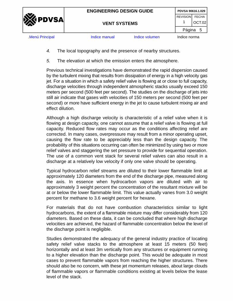
4. The local topography and the presence of nearby structures.
5. The elevation at which the emission enters the atmosphere.
Previous technical investigations have demonstrated the rapid dispersion causedby the turbulent mixing that results from dissipation of energy in a high velocity gasjet. For a situation in which a safety relief valve is flowing at or close to full capacity,discharge velocities through independent atmospheric stacks usually exceed 150meters per second (500 feet per second). The studies on the discharge of jets intostill air indicate that gases with velocities of 150 meters per second (500 feet persecond) or more have sufficient energy in the jet to cause turbulent mixing air andeffect dilution.
Although a high discharge velocity is characteristic of a relief valve when it isflowing at design capacity, one cannot assume that a relief valve is flowing at fullcapacity. Reduced flow rates may occur as the conditions affecting relief arecorrected. In many cases, overpressure may result from a minor operating upset,causing the flow rate to be appreciably less than the design capacity. Theprobability of this situations occurring can often be minimized by using two or morerelief valves and staggering the set pressure to provide for sequential operation.The use of a common vent stack for several relief valves can also result in adischarge at a relatively low velocity if only one valve should be operating.
Typical hydrocarbon relief streams are diluted to their lower flammable limit atapproximately 120 diameters from the end of the discharge pipe, measured alongthe axis. In essence when hydrocarbon vapors are diluted with air toapproximately 3 weight percent the concentration of the resultant mixture will beat or below the lower flammable limit. This value actually vanes from 3.0 weightpercent for methane to 3.6 weight percent for hexane.
For materials that do not have combustion characteristics similar to lighthydrocarbons, the extent of a flammable mixture may differ considerably from 120diameters. Based on these data, it can be concluded that where high dischargevelocities are achieved, the hazard of flammable concentration below the level ofthe discharge point is negligible.
Studies demonstrated the adequacy of the general industry practice of locatingsafety relief valve stacks to the atmosphere at least 15 meters (50 feet)horizontally and at least 3m vertically from any structures or equipment runningto a higher elevation than the discharge point. This would be adequate in mostcases to prevent flammable vapors from reaching the higher structures. Thereshould also be no concern, with these jet momentum releases, about large cloudsof flammable vapors or flammable conditions existing at levels below the leaselevel of the stack.

REVISION FECHA
ENGINEERING DESIGN GUIDE
VENT SYSTEMS OCT.021
PDVSA 90616.1.029
Página 6
�����
.Menú Principal Indice manual Indice volumen Indice norma
b. Mist Emission
Mists, as referred to in this guide, result from condensation following emissions.
Condensed mists are finely divided, the diameters of most drops is less than 10micrometers, with few larger than 20 micrometers. Mechanical sprays do notusually contain many drops below 100 micrometers in diameter.
Whether vapors will condense in appreciable quantities when released to theatmosphere will depend on the stream composition, atmospheric temperature,and exit velocity. Frequently, the assumption is made that if the lowest anticipatedatmospheric temperature is below the dew point of a released hydrocarbon,significant condensation will occur.
In cases in which vapor discharges from safety relief valves condense,consideration must be given to how the condensation influences the formation ofa flammable atmosphere. Combustible liquid mists in air are capable ofpropagating flame when ignited, even though the liquid is so involatile that noappreciable amount of vapor is formed at the ambient temperature. Thus, mistsof flammable liquids can present a hazard even at temperatures well below theflash point.
In cases in which calculation indicates that vapor discharges from safety reliefvalves may condense, it is possible for coalescence to produce droplets thatrapidly settle to grade rather than dispersing as a mist similar to vapors. Thehydrocarbon partial pressure at which the calculated cooling curve intersects thedewpoint curve should be considered indicative of bounding the region in whichcoalescence seems unlikely.
Although no conclusive data are now available, it is suggested that condensationat hydrocarbon partial pressures of 34 kilopascals absolute (5 pounds per squareinch absolute) or lees should be treated as finely divided mists withoutcoalescence. In the absence of coalescence, the effect of gravity should benegligible since the free–fall velocity of 10 micrometer hydrocarbon particles in airis approximately 3 millimeters per second (0.01 feet per second). Therefore, evenwith very light wind, the discharge from an elevated location will travel aconsiderable distance before reaching grade.
Based on the foregoing factors pertaining to the dispersion and combustioncharacteristics of a mist, it can be concluded that as long as the condensateremains in finely divided form and is airborne, the mixture can be treated forflammability and dispersion characteristics as though it were completelyvaporized.

REVISION FECHA
ENGINEERING DESIGN GUIDE
VENT SYSTEMS OCT.021
PDVSA 90616.1.029
Página 7
�����
.Menú Principal Indice manual Indice volumen Indice norma
c. Liquid Emission
Unlike discharges composed of vapor or mist, which rapidly disperse when ventedto the atmosphere at high velocity, liquid discharges settle to grade. If volatilecomponents are present a flammable atmosphere may result. The risk of fire orexplosion may be high if appreciable quantities of liquid hydrocarbon are releasedto the atmosphere when the ambient temperature is at or above the flash pointof the liquid or when their presence concur whith an unexpected source of ignition.
Theoretically, liquide that have a flash point above the maximum anticipatedambient temperature would not vaporize enough to create a flammableatmosphere. However widespread spraying of oil droplets could create concernin an emergency and could constitute a serious nuisance. Also, minor fires mightoccur if liquid came in contact with very hot line or equipment.
Fluids that are discharged from relief devices as liquide should be handled in thefollowing manner.
Flammable liquide with atmospheric boiling points above 35°C (95°F) should bedirected downward within 10–20 cm (4–8 inches) of grade and shielded to preventsplashing of liquid and debris. The discharge should be in or near a trapped drainor some other safe location.
Flammable liquide with atmospheric boiling points between 35°C (95° F) and–50°C (58° F) should be routed to a liquid knockout pot to separate vapor andliquid. The vapors should be disposed of as in the section on Vapors Emission.
Flammable liquide with atmospheric boiling points below –50°C (–58 °F) shouldbe directed upward and discharged at least 45 meters (150 feet) above grade orabove the tallest column in the unit. The discharge should be a minimum of 2.4m (8 feet) above the shutoff valve underneath the relief device.
Nonflammable liquids that are not hazardous to personnel with atmosphericboiling points above 35°C (95°F) should be directed downward within 10–20 cm(4–8 inches) above grade and shielded to prevent splashing of liquid and debris.
Nonflammable liquids that are not hazardous to personnel with atmosphericboiling points below 35°C (95°F) should be discharged up in the air a minimumof 2.4 m (8 feet) above the shutoff valve under the relief device.
Nonflammable liquide that are hazardous to personnel must be discharged in asafe manner to prevent personnel injury. Each case will require individualconsideration because of the many types of hazards that can be encountered.
d. Sources of Ignition
The possibility of accidental ignition of the outflow of hydrocarbon vapors from asafety relief valve can best be analyzed in terms of four possible causes of ignition:outside sources (including open flames, hot surfaces, or nonclassified electricalequipment), lightning, static electricity, and autoignition.

REVISION FECHA
ENGINEERING DESIGN GUIDE
VENT SYSTEMS OCT.021
PDVSA 90616.1.029
Página 8
�����
.Menú Principal Indice manual Indice volumen Indice norma
1. Outside ignition sources: The possible existence of outside ignitionsources such as open flame, hot surfaces, and nonclassified electricalequipment in stalled in surrounding areas and on structures will be knownor can be anticipated. With jet momentum releases from safety relief valves,emission points can be located so that the flammable pattern evolved will notreach such sources. This becomes more difficult where wind dominated lowvelocity releases are involved, since flammable patterns could extendconsiderable distance from the release point. Also in these instances, theignition potential from temporary sources, such as automotive equipment onland, floating equipment on offshore or lake operations, or hot activities(welding) must be recognized. Therefore, with normal atmosphericreleases, outside ignition sources can be readily avoided by proper locationof vents. On the other hand, with low velocity, low momentum releases, theremust be a careful design check of conditions at various emission rates andatmospheric conditions to avoid the potential of ignition by outside sources.
2. Lightning: Discharges from open atmospheric vents have been ignited bylightning. Except for emergency discharges associated with power outagesthat may occur during thunderstorms, the probability of lightning occurringsimultaneously with the opening of a relief valve is negligible. Intermittentdischarges over long periods and continous discharges, for example, fromleaking relief valves, increase the probability of lightning ignition.
3. Static electricity: During high velocity discharges from gas wells,compression plants or gas systems to the atmosphere, static chargessufficient to cause sparks and ignition are developed. The condensate zonein the jet of well head gas apparently tends to produce a high level of charge,although ignition does not actually occur. Another theory relating to staticignition propose that gas flow through a piping system during ventinginduces a static charge on any solid or liquid particles in the pipe stream thatcontact the pipe wall. As the gas reaches the sharp edges of the vent outlet,static discharges may occur either by complete electrical breakdown (sparkdischarge) or by partial breakdown (corona discharge).
The experience of pipeline companies (who customarily discharge naturalgas to the atmosphere at low elevations) includes gas pressures as high as6200 kilopascals gage (900 pounds per square inch gauge) and dischargerate as high as 650000 pounds per hour (295200 kilograms per hour) froma single vent stack.
Hence, the probability of ignition by static electricity is very low because ofa relatively weak charge buildup in the jet and reasonable isolation from thewell–grounded vent stack.

REVISION FECHA
ENGINEERING DESIGN GUIDE
VENT SYSTEMS OCT.021
PDVSA 90616.1.029
Página 9
�����
.Menú Principal Indice manual Indice volumen Indice norma
This conclusion pertains to hydrocarbon vapor releases. Experienceindicates that streams with high hydrogen content are susceptible to ignitionby static electricity as a result of the described mechanism because ofelectrostatic discharges at the sharp edge of the vent outlet. The NationalAeronautics and Space Administration (NASA, USA) investigated thisphenomenon and found such electrostatic discharges can be prevented bythe installation of a toroidal ring on the vent stack outlet. The ring inhibits theflow of current at the vent stack lip by removing the cause of turbulencecharacteristics of a sharply defined vent exit. (See Figure 3).
4. Autoignition: Relief streams, which are above the autoignition temperatureon the upstream side of the valve, may ignite spontaneously on contact withair unless sufficient cooling occurs before a flammable vapor air mixture isformed. For this reason, these hot streams should usually be routed to aclosed system, cooler, or quench tower. Under some circumstances, withproper location of the discharge stack, ignition can be tolerated.
4.3 Toxic Vapors
4.3.1 Although most vapor streams would be harmful to breathe at high concentrations,the majority present little or no risk to personnel when–discharged from safetyrelief valves at a remote location. The average person can tolerate short–termexposure to most hydrocarbon vapors at concentration levels equivalent to orabove the lower flammable limit. Thus, if facilities are designed to avoid flammableatmosphere the results of inhalation at the same location will not be injurious.
4.3.2 However, certain refinery and production streams may contain vapors that aredangerous at extremely low concentrations: for example, hydrogen sulfide vaporscan cause unconsciousness and death within seconds following exposure to aconcentration above 1000 parts per million. This is approximately one–tenth theconcentration representing the lowest flammable limits of any hydrocarbon.Therefore where hydrogen sulfide or similar toxic materials are present in a reliefstream, an investigation should be made to predict the maximum downwindconcentration at any location where personnel may be exposed. Special attentionshould be given to adjacent elevated structures that may he within the path of theplume and will thus be subject to relatively high concentrations. If the presenceof toxic vapors can not be avoided proper disposal system must be designed andinstalled, and safety equipment must be available on site.
4.3.3 The ground level concentration of toxic vapors at any location downwind a stackcan be estimated as described in PDVSA Guide 90616.1.020.

REVISION FECHA
ENGINEERING DESIGN GUIDE
VENT SYSTEMS OCT.021
PDVSA 90616.1.029
Página 10
�����
.Menú Principal Indice manual Indice volumen Indice norma
5 VENT SYSTEMS5.1 Process gases released from pressure safety valves (PSV’s) or depressurization
valves must be collected in two closed vent systems defined as low and highpressure relief systems (LP and HP relief). Typically, the LP relief collects gasesfrom equipment operating below 31 bar (450 PSIG), and HP relief from equipmentoperating at 31 bar (450 PSIG) and above, nevertheless other pressures couldbe set according to the operating conditions of the plant. Both headers will berouted to a common blowdown knock out drum (BDKO).
5.2 Systems shall be designed so that 90% depressurization of the plant must beachieved within 5 minutes without overpressure of any component.
5.3 Headers shall be in elevated position inside compression modules and slopeddownward to the BDKO drum (usually the slope is in the order of 1%). The BDKOdrum shall be horizontal type connected through a short line (or directly) to a ventstack. The gas outlet should be connected through a single point. Methods ofseparators calculations are presented in PDVSA Engineering GuidesMDP–03–S–03 “Liquid–Vapor Separators”.
5.4 Collected liquids will be pumped to the common K.O drum at plant inlet or at anyother suitable location. The pump should be spared, start automatically at highliquid level and cut out at low liquid level and shall be connected to the emergencypower generator. An on/of f light in the control room should indicate on/off of thepump. The pumps shall be sized for specific gravity range from 0.6 to 1.0.
5.5 The complete system shall be continuously purged at a low and sufficient rate. Arestriction orifice should be installed to pass the required amount. Provide purgeconnection at the farthest end of vent header to ensure that the entire system willremain purged.
5.6 A flashing light and an audible alarm should be activated in case of venting toprevent boats presence (offshore location). Confusion with fire or gas alarmshould be avoided.
5.7 For atmospheric vents the discharge shall be vertical, with the vent pipe:
– Being at least 2 m long.– Terminating at least 5 m above grade.– At least 3 m above the tallest structure within an 8 m radius.– At least 30 m horizontally from furnaces, boilers etc. or their air intakes.
5.8 In addition, for production facilities and gas compression plants the dischargeshall be:

REVISION FECHA
ENGINEERING DESIGN GUIDE
VENT SYSTEMS OCT.021
PDVSA 90616.1.029
Página 11
�����
.Menú Principal Indice manual Indice volumen Indice norma
– Remotely located at field installations, no less than “X” meters from operatingareas and downwind from them.
– Preferably located no less then “Y” meters from operating areas in gascompression plants and downwind from them.
– “X” and “Y” should be agreed upon by the engineering, safety and operatingorganizations.
5.9 The possibility that the vented stream catches fire should be considered, in whichcase the heat input on neighbouring working platforms shall not exceed 5400kcal/m2–hr (2000 BTU/sq.ft.hr.) nor be damaging to the nearest structures. Aflame arrestor should not be fitted.
5.10 The tail pipes shall be provided with a steam hose connection or other systemsfor flame extinguishing.
5.11 The vent outlet velocity shall not be lees than 150 m/sec (500 ft/sec) and nothigher than 80% of the sonic velocity at the rated capacity. The tail pipe shall notbe smaller in diameter than the relief valve outlet.
5.12 The bottom of the vent shall be provided with a 1/2” dia (minimum) drain at thelowest point, which should be opened frequently (i.e. once a week), to prevent theliquid build up. The vent pipe shall be adequately supported against reactionforces.
6 VENT STACKS
6.1 Sizing6.1.1 The size of a vent stack is determined by the available pressure drop and by any
minimum velocity required to prevent hazardous conditions due to combustibleor toxic material at grade or working levels. Normally, a size is selected that willresult in a high discharge velocity for example, velocity of 150 meters per second(500 feet per second) will provide excellent dispersion. The size should bechecked to ensure that sonic flow is not established or, if it is, that allowance hasbeen made for the pressure discontinuity at the discharge end in calculatingpressure drop. A sample calculation is presented afterwards.
6.1.2 Assume the following conditions: The maximum relief rate, W, is 113400 kg/h(250000 pounds per hour). The molecular weight of the vapor, M, is 44. Thetemperature of the vapor just inside the tip, T. is 361°K (650°R). The exit velocity,V, is 150 meters per second (500 feet per second)).
6.1.3 The pressure of the vapor just inside the vent tip, P, is 101 kilopascals absolute(14.7 pounds per square inch absolute). The gas constant, R, is 8.3 for metricunits (10.7). The density ρ is then calculated as follows:

REVISION FECHA
ENGINEERING DESIGN GUIDE
VENT SYSTEMS OCT.021
PDVSA 90616.1.029
Página 12
�����
.Menú Principal Indice manual Indice volumen Indice norma
� � MPRT
kilograms per cubic meter�(44) (101)(8.3) (361)
� 1.48
In British units, this translates to:
� � MPRT
pounds per cubic foot�(44) (14.7)
(10.7) (650)� 0.1
The tip size is determined as follows:
Tip size � W�V
113400(1.48) (150) (3600)
� 0.14 square meter
In British units, this translates to.
Tip size � W3600 �V
250000(3600) (0.1) (500)
� 1.39 square feet
Thus the pipe diameter should be about 16 inches nominal pipe size.
6.2 Design Details
6.2.1 Once the vent stack has been sized in accordance with recommendations,indicated in section 6.1, the design is primarily a structural problem.
6.2.2 If the vent stack is in a location remote from other facilities, a guyed stack willusually be as satisfactory as, and more economical than, providing a structure tosupport the stack. Vent stacks are frequently located in a process area thatcontains equipment connected to the stack. It is often possible to support the stackfrom a fractionating tower, chimney, or other tall structure in the unit. Such anarrangement provides for economical discharge at a safe elevation.

REVISION FECHA
PDVSA
Página 13
�����
.Menú Principal Indice manual Indice volumen Indice norma
6.2.3 The height of the vent stack is selected so that the concentration of vapor at a pointof interest is well below the lower flammable limit of the vapor. Usually 0.1–0.5times the lower flammable limit is an acceptable concentration. Toxicity requiresmuch lower concentrations on certain applications and is therefore the controllingfactor. The radiant heat intensity for vent stack should also be checked in the eventa relieving vapor should ignite; calculation should be made assuming a flow rateequivalent to an outlet velocity of 150 m/seg (500 FPS), this is done by the samemeans as for flare stacks, and the came limits apply for radiant heat intensity.Radiant heat levels sometimes take precedence over dispersion in determiningstack height. Methods of flare calculations are presented in PDVSA Guide90616.1.021.
6.2.4 In every vent stack installation, careful consideration should be given to twopotential problems: accumulation of liquid in line terminating at the vent stack andaccidental ignition by lightning. Accumulation of liquid in line to the vent stack mayresult from leakage into the system of high–molecular–weight vapors thatcondense at ambient temperature. If appreciable quantities of liquid collect, theywill subsequently be discharged to the atmosphere when vapors are released intothe system.
6.2.5 To avoid liquid accumulation, it is important to prevent pockets from occurring thelines and to dope the system to a low–point dram. These drains can be installedto function automatically by use of a properly designed seal. The height of the sealshould provide a head equivalent to at least 1 1/2 times the backpressure underthe maximum relief load to avoid release of vapor through the seal. As analternative to a sealed dram, a small disengaging drum may be installed at thebase of the vent stack. This type of installation is recommended where significantquantities of liquid may occur.
6.2.6 The possibility that vapors from the vent stack may be accidentally ignited bylightning or other sources usually makes a remote–controlled snuffing steam,water (for cooling) or CO2 connection necessary on the vent stack. This isspecially true in locations where the incidence of lightning is high or where accessto the point of discharge would be difficult with conventional fire–extinguishingequipment. Each system consists of CO2 cylinders, connected by flexibledischarge loops to a manifold which is piped to two opposed discharge nozzles,installed approximately 4.5 m (15 feet) below the top of the vent stack. Theoperation of the valves is manual.
6.2.7 It is frequently impractical to size the steam supply line for a rate sufficient toextinguish a fire under maximum venting conditions, however, steam would stillbe essential, since in most cases, vent fires occur when the only flow to the systemconsist of leakage or minor venting. With relatively small amounts of vented vaporin small stacks, it is possible to dilute the vented vapor to the point where

REVISION FECHA
ENGINEERING DESIGN GUIDE
VENT SYSTEMS OCT.021
PDVSA 90616.1.029
Página 14
�����
.Menú Principal Indice manual Indice volumen Indice norma
combustion ceases. It requires on the order of one pound of steam per cubic footof vented vapor to dilute a flammable vapor to this point. As the vented vapor rateand stack size increase, the steam rate for dilution to the extinguishing ratiobecomes excessive, and. it becomes necessary to depend on a “blowout”phenomena for achieving extinguishment. Blowout results from the combinedeffects of dilution with steam and outside air at high velocities and cooling resultingfrom the dilution.
6.2.8 Furthermore, unless steam or cooling water and CO2 is supplied, if ignition occurswhen venting at or near the maximum design load, the fire will quite likely continueto burn when the cause of overpressure is corrected with an accompanyingreduction in venting.
6.3 Vent ValvesVent valves are frequently installed for relieving pressure in piping systems priorto opening for maintenance. In some cases the pressure can be safely relievedby cautiously opening a flange or loosening a threaded connection. For example,it is not necessary to install vent valves under pressure gages in the typical plantcooling water system. However, when fluids hazardous to personnel are handled(phosgene, carcinogens, strong caustic, or acid solutions, etc.) vent valves shouldbe provided in portions of the piping where the fluid can be trapped underpressure.
6.4 Local Vents
6.4.1 Often neglected from a safety point of view are local vents, such as those on fixedroof tanks and lube oil/seal oil tanks.
6.4.2 The hazardous area around local vents shall be classified according to thefrequency of flammable vapor release. In addition, high ignition risk vents, suchas those on oil savers shall be positioned so as not to endanger nearbyequipment, especially electric cables, when ignited.
6.4.3 In complying with hazardous area requirements, special care should be taken notto extend a tank vent to a height where overfilling the tank will overpressures it dueto the liquid column in the vent. In such cases, a separate pressure/vacuum valveor permanent vent drains must be installed.
6.4.4 During drilling, flammable vapors released from low pressure or atmospheric mudseparators may be vented without being ignited through the vent line attached tothe derrick.
6.4.5 Vents from atmospheric systems shall not be connected to a closed processventing system, since higher pressure from other sources might causeoverpressure.

REVISION FECHA
ENGINEERING DESIGN GUIDE
VENT SYSTEMS OCT.021
PDVSA 90616.1.029
Página 15
�����
.Menú Principal Indice manual Indice volumen Indice norma
7 REMOVAL OF ENTRAINED LIQUID
7.1 When complex mixtures of hydrocarbon vapors at high temperatures arereleased into a vent system, cooling occurs and liquide condense out as the dewpoint is reached. In the case of a flare, even a small amount of entrained liquidswill cause a smoky flare and great emissions of light. Heavy carryover of largedrops can produce a rain of liquid, thus it is necessary to prevent entrainment byproviding a knockout drum.
7.2 It is estimated that the loss of heat in a vent system is 24.4 to 48.8 kcal/ m2 °C (5to 10 British thermal units per square foot of surface per degree Fahrenheit)temperature difference between the steel and the atmosphere. The range is duepartly to the effect of wind, while the rate of cooling would be greater in a rainstorm. The vapor space in the knockout drum must be sufficiently large to reducethe vapor velocity below the drop–out velocity of the fine entrained droplets. APIRP 521 present a method for sizing knockout drums to remove droplets of 150microns and larger. Drums equipped with pumps on automatic control shouldhave sufficient capacity for the maximum liquid accumulation expected in 15minutes. The pumps must be capable of handling the lowest molecular weightliquids that are likely to accumulate.
7.3 If a very heavy flow of vapor should occur suddenly, previously condensed liquidemay be entrained and carried out the stack. Experiments carried out showed therelative effectiveness of cyclones, mist eliminators, water seals, and knockoutdrums. The use of mist eliminators is objected because they may become pluggedand increase the pressure drop of the systems. Experience has demostrated thata combination of water seals with vane type mist eliminators is a good design toprevent liquid carryover. Cyclones are effective at high velocities but poor at lessthan design flows.
7.4 Design ConsiderationBlowdown drums for normal hydrocarbon service are designed in accordancewith the following (see Figures 4 and 4A for typical refineries and gas compressionplants respectively):
7.4.1 A typical non–condensible blowdown drum and its associated equipment andheaders are illustrated in Figure 4.
7.4.2 A single blowdown drum may be used for more than one process unit, ifeconomically attractive. However, when this is done, all units served by it must beshut down in order to take the drum out of service, unless cross connections aremade to another system of adequate capacity.

REVISION FECHA
ENGINEERING DESIGN GUIDE
VENT SYSTEMS OCT.021
PDVSA 90616.1.029
Página 16
�����
.Menú Principal Indice manual Indice volumen Indice norma
7.4.3 Normally all closed safety valve discharges are combined into one headerentering the drum, although separate headers and inlet nozzles are acceptableif economically advantageous
7.4.4 Sizing of the blowdown drum and location of the level instruments are based onthe following (see Figure 4 and 4A):
a. Liquid holdup below the LH (CO) A (A–B in Figure 4 and 4A) is the light endsstream diversion requirement or the closed drainage requirement for residualprocess liquide at a normal shutdown, whichever is greater. This closed dramrequirement is taken as 10% of the total liquid hydrocarbon inventory of all vesselsin one process unit which are provided with closed dram header connections. Thisassumes that 90% of the liquid inventory of these vessels can be removed bypressuring or pumping out through normal process disposal routes. The processunit to be used for sizing purpose is the one which has the largest closed dramrequirement and which can shutdown independently for turnaround. Inventory ofvessels is calculated at the top of the working level range, excluding tray holdupand the contents of piping. In the case of vessels containing large liquidinventories, e.g., surge drums, the individual closed dram header requirementmay be reduced below 10%, where appropriate, by taking credit for alternativemeans of disposal of the liquid contents, e.g. water displacement to storage.
b. The space in the drum above the LH (CO) A (Above the upper LH (CO) A whentwo are installed) is made up of a holdup capacity (B–D in Figure 4 and 4A) for 30minutes accumulation of liquid safety valve releases, plus a vapor space (D–F)for the associated vapor release. The drum sizing is determined by the singlecontingency which requires the maximum combined space B–D plus D–F.
c. In addition to the contingency which requires the maximum combined space B–Dplus D–F and which determines the drum sizing, other contingencies areconsidered as follows:
1. The single contingency which results in the largest accumulation (B–E) ofliquid safety valve releases during 30 minutes, regardless of any associatedvapor rate. The level at point E is used for pumpout pump sizing.
2. The single contingency which results in the largest vapor load regardless ofany associated liquid load, is used to determine the maximum requiredvapor space C–F, and a high level alarm is placed at point C.
d. In considering the contingencies described in paragraphs b and c above, vaporand liquid loads are evaluated on the following basis:
1. Vapor load considerations must include all safety valve, emergency vaporblowdown and vapor stream diversion sources which release as a result ofa single contingency.

REVISION FECHA
ENGINEERING DESIGN GUIDE
VENT SYSTEMS OCT.021
PDVSA 90616.1.029
Página 17
�����
.Menú Principal Indice manual Indice volumen Indice norma
2. Liquid loads are considered from all safety valves that discharge as a resultof a single contingency, plus in each case an allowance for knockout drumliquids (fuel gas K.O. drums, absorber overhead K.O. drums) equal to theinventory of all drums which discharge to the blowdown drum, at their LHApoint. In a typical gas compression plant, this allowance is not necessarysince those liquids are not directed to the vent knock out drum, they areconnected either to the suction plant knock out drum or with another suitablefacility.
3. Vapor space velocities normally should not exceed 100% of critical;experience demonstrates that this keeps liquid entrainment into the flare linewithin acceptable limits. However, a velocity of 175% of critical is permittedwhen one is applying the “1.5 times Design Pressure Rule” to remotecontingencies. The constant value 0.157 could be different if any type ofinternals are installed inside the vessel.
Vc � 0.157�L � �v
�v�
Where:
VC = Critical vapor velocity, ft/s
ρL = Liquid density, lb/ft3 at operating conditions.
ρV = Vapor density, lb/ft3 at operating conditions.
Crinkled wire mesh screens are not permissible.
4. The depth of the vapor space should under no contingency be less than 20%of the drum diameter, or less than 30 cm (12 inch).
e. A LL (CO) A with local manual reset is provided to trip the pumpout pump whenthe liquid has been pump down to a low level.
7.4.5 The blowdown drum design pressure is 3.4 bar g. (50 psig) or less.
7.4.6 The maximum allowable operating pressure in the blowdown drum is determinedby the lower of the following:
a. The maximum allowable back pressure on safety valves which discharge to theblowdown drum, according to set pressure and type of safety valve, or
b. The pressure at which vapor diversion from any gas compressor suction to theblowdown drum is required to be released. These facilities are normally providedon cat cracker and steam cracker process gas compressors.
c. The maximum allowable operating pressure on any condensible blowdown drum,water disengaging drum, etc., which vents into the same flare or vent header.

REVISION FECHA
ENGINEERING DESIGN GUIDE
VENT SYSTEMS OCT.021
PDVSA 90616.1.029
Página 18
�����
.Menú Principal Indice manual Indice volumen Indice norma
7.4.7 The blowdown drum design temperature is set by the extremes of emergencyoperating temperature which can result from any of the streams tied into it. Ifmaterials are handled at temperatures below 1600 (60°F), or if they canautorefrigerate to below 1600 (60°F), a minimum design temperature must alsobe specified.
7.4.8 Blowdown drum materials must be adequate for any corrosive substance thatmay be released into it, and for the temperature limits defined by paragraph 7.1.7above. The corrosion allowance shall be 3 mm.
7.4.9 Depending on the weather or operating conditions at the plant site a heating coilcould be provided in the blowdown drum for deicing, winterizing and weatheringpurposes. Sizing of the coil is based upon weathering off the light ends from theflashed liquids at the maximum level accumulated as a result of any of the designcontingencies described in paragraph 7.1.4 above. This material must beweathered in two hours to temperature and vapor pressure conditions which willpermit safe pumpout to associated shops or other receiving facilities. In somecases weathering must be followed by cooling of the pumpout stream (seeparagraph 7.1.13 below). For most applications when steam is available, a steamcoil consisting of a nominal 60 m (200 ft) of 2 inch pipe is adequated. The coilshould be sloped to insure condensate drainage.
7.4.10 For services where a steam coil may be exposed to cold or autorefrigeratedliquids, the design should be such as to prevent blockage by freezing of steamcondensate. The following methods are available to achieve this:
a. A 5 cm (2 inch) steam trap by pass direct to sewer. This is required in all caseswhere temperatures below 0°C (32°F) may occur in the blowdown drum.
b. Connections for methanol injection into the steam coil inlet and outlet piping fordeicing.
c. Use of vertical double–pipe (bayonet type) steam heaters.
d. Use of a hot oil heating medium to the coil, or a cascade heating system (e.g.,steam, methanol).
7.4.11 In some cases the drum is provided with a drawoff boot of nominal 60 cm (2 ft)diameter by 90 cm (3 feet) in height, with a separate steam coil fabricated from1 inch pipe. Normally it is not necessary to withdraw hydrocarbon and waterseparately, and the pumpout pump takes suction from the bottom of the boot. TheLL (CO) A is located as close as possible to the top of the boot to ensure that thepump is shutdown before losing suction.

REVISION FECHA
ENGINEERING DESIGN GUIDE
VENT SYSTEMS OCT.021
PDVSA 90616.1.029
Página 19
�����
.Menú Principal Indice manual Indice volumen Indice norma
7.4.12 An electrical or in some cases a steam–driven manually controlled pump is usedfor the pumpout service. A reciprocating pump is used due to its greater ability tohold suction with volatile liquids; however, if a centrifugal pump is used, bothsuction and discharge lines must be vented back to the drum, the discharge ventbeing sized for 15% of the pump capacity. Pump sizing is based on pumping outin 2 hours the total drum contents from the maximum accumulated liquid level, dueto the wide range of fluids handled, the pump should be specified for 2.1 to 2.9m (7 to 8 ft) NPSH requirement at the suction flange. Drum elevation should besuch as to meet the pump NPSH requirement. The pump design temperatureshould be the same as that of the blowdown drum, and design pressure is setaccording to the disposal routing downstream.
7.4.13 Disposal of pumpout material from the blowdown drum at the refineries is normallyto pressure shops storage, light atmospheric slops storage, or other atmospherictankage. At the gas compression plants these liquids are directed either to thesuction plant knock out drum or another suitable location. Design features mustbe incorporated to avoid the hazards of excessive vapor evolution or boil–overwhich can result from routing light or hot materials to atmospheric tankage.
Requirements for weathering off light ends from liquid accumulated in theblowdown drum are defined in paragraph 7.1.9 above.
In addition, a cooler should be provided in the discharge line from the pumpoutpump if either of the following applies:
a. The blowdown drum can receive hot liquids above 93°C (200°F), or
b. The blowdown drum liquid (after weathering, if necessary), if routed to anatmospheric tank for disposal, could result in the true vapor pressure of materialin the tank exceeding 0.9 bar (13 psia).The cooler should be sized to cool the maximum pumpout flow to 49°C (120°F).
8 NOISE
8.1 Excessive Noise Levels8.1.1 Noise created from the venting of hydrocarbons may cause problems due to either
the potential hearing loss of exposed personnel or the nuisance created insurrounding areas.
8.1.2 The noise generated by a pressure relief valve discharging to the atmosphere canbe relatively loud. Emergency relief is ordinarily of short duration and occursinfrequently, so a high noise level is usually acceptable.
8.1.3 The allowable noise intensity and duration should be evaluated at areas whereoperating personnel would normally work or at property limits. Where two or morepressure relief valves can discharge to the atmosphere simultaneously, thecombined effects will need to be evaluated.

REVISION FECHA
ENGINEERING DESIGN GUIDE
VENT SYSTEMS OCT.021
PDVSA 90616.1.029
Página 20
�����
.Menú Principal Indice manual Indice volumen Indice norma
8.2 Noise CalculationThe noise level at 30 meters (100 feet) from the point of discharge to theatmosphere can be approximated by equation:
L log10�1�2 MC2�L100 = L(from figure 5) +
Figure 5 ilustrates the noise intensity measured as the sound pressure level at 30meters (100 feet) from the stack tip versus the pressure ratio across the safetyvalve.
The following symbols are used in the procedure for calculating the noise level:
M = Mass flow through the valve, in kilograms per second (slugs per second).
C = Speed of sound in the gas at the valve, in meters per second (feet persecond).
Notes:
In feet per second:
C � 223 kTMolecular Weight�
In meters per second:
C � 91.2 kTMolecular Weight�
Where,
k = ratio of the specific heats in the gas
T = gas temperature in degrees Rankine (kelvins)
PR = ratio of the upstream to the downstream pressure across the safety valve(absolute)
An example of calculating in English units, the noise level at 100 feet from the pointof discharge to the atmosphere is presented below:
a. Calculate 1/2 MC2: in watts. Divide the weight flow (pounds per second) by 32 toobtain M. Multiply 1/2 MC2 (foot pounds per second) by 1.36 to obtain 1/2 MC2 inwatts.
b. Calculate 10 log10 (1/2 MC2).
c. In Figure 5, enter PR as the abscissa and read the ordinate.
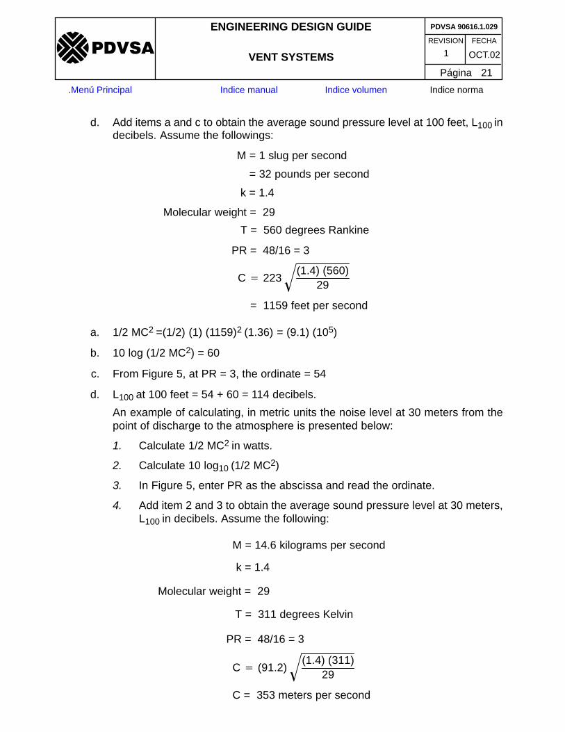
C � (91.2)(1.4) (311)
29�
M = 14.6 kilograms per second
k = 1.4
Molecular weight = 29
T = 311 degrees Kelvin
PR = 48/16 = 3
C = 353 meters per second
REVISION FECHA
ENGINEERING DESIGN GUIDE
VENT SYSTEMS OCT.021
PDVSA 90616.1.029
Página 21
�����
.Menú Principal Indice manual Indice volumen Indice norma
d. Add items a and c to obtain the average sound pressure level at 100 feet, L100 indecibels. Assume the followings:
C � 223(1.4) (560)
29�
M = 1 slug per second
= 32 pounds per second
k = 1.4
Molecular weight = 29
T = 560 degrees Rankine
PR = 48/16 = 3
= 1159 feet per second
a. 1/2 MC2 =(1/2) (1) (1159)2 (1.36) = (9.1) (105)
b. 10 log (1/2 MC2) = 60
c. From Figure 5, at PR = 3, the ordinate = 54
d. L100 at 100 feet = 54 + 60 = 114 decibels.
An example of calculating, in metric units the noise level at 30 meters from thepoint of discharge to the atmosphere is presented below:
1. Calculate 1/2 MC2 in watts.
2. Calculate 10 log10 (1/2 MC2)
3. In Figure 5, enter PR as the abscissa and read the ordinate.
4. Add item 2 and 3 to obtain the average sound pressure level at 30 meters,L100 in decibels. Assume the following:

REVISION FECHA
ENGINEERING DESIGN GUIDE
VENT SYSTEMS OCT.021
PDVSA 90616.1.029
Página 22
�����
.Menú Principal Indice manual Indice volumen Indice norma
a. 1/2 MC2 = (1/2) (14.6) (353)2 = (9.1) (105)
b. 10 log10 (1/2 MC2) = 60
c. From Figure 5, at PR = 3 the ordinate = 54
d. L100 at 30 meters = 54 + 60 = 114 decibels.
Note: The calculations are based on spherical spreading of the sound. If distancesmuch larger than the height of the vent above ground are of concem, add 3decibels to the calculated result to correct for hemispherical diffusion.

Fig 1. VENT STACK WATER SPRAY
12”
� 1 1/2”
SPRINKLING NOZZLES (3/4”)
PIPING SUPPORTS � 1 1/2”
CO2 CONNECTION
� 1 1/2”
LINE � 2”
� 2”
GATE VALVE � 2”
DRAIN LINE
STACK PLATFORM
REVISION FECHA
ENGINEERING DESIGN GUIDE
VENT SYSTEMS OCT.021
PDVSA 90616.1.029
Página 23
�����
.Menú Principal Indice manual Indice volumen Indice norma
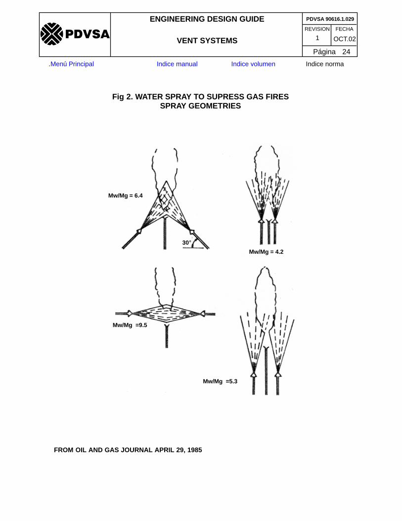
Fig 2. WATER SPRAY TO SUPRESS GAS FIRESSPRAY GEOMETRIES
Mw/Mg = 6.4
Mw/Mg = 4.2
Mw/Mg =9.5
Mw/Mg =5.3
FROM OIL AND GAS JOURNAL APRIL 29, 1985
30�
REVISION FECHA
ENGINEERING DESIGN GUIDE
VENT SYSTEMS OCT.021
PDVSA 90616.1.029
Página 24
�����
.Menú Principal Indice manual Indice volumen Indice norma

Fig 3. TOROIDAL RING VENTS
Toroidal anti–static discharge ring(Stainless steel tubing, wall thincknessnot critical)
Weld
D
Vent Stack
REVISION FECHA
ENGINEERING DESIGN GUIDE
VENT SYSTEMS OCT.021
PDVSA 90616.1.029
Página 25
�����
.Menú Principal Indice manual Indice volumen Indice norma
Stack diameter D,inches
Required Toroidal Ringdiameter d, inches
Less than 8 1/2
8 to 12 3/4
12 to 20 1
20 to 24 2
Over 24 3

Fig 4. NON–CONDENSIBLE BLOWDOWN DRUM SIZING(REFINERIES)
VAPOR AND LIQUID SAFETY VALVE RELEASESEMERGENCY VAPOR BLOWDOWNSFUEL GAS AND ABSORBER KNOCKOUT DRUM DRAINSVAPOR STREAM DIVERSION
MAX. LIQUID LEVElL FOR PUMPOUTPUMP SIZINGMAX. LIQUID LEVEL FOR DRUM SIZING
LHA
TI
LL(CO) A
STEAM(1)
PUMPOUT FROMMAXIMUM
LIQUID LEVEL IN2 HOURS
E
A
D
B
*
C
VAPOR SPACE FOR 100% OF CRITICAL VALOCITY
30 MINUTES’ LIQUID FROM SAFETY VALVESPLUS
ALLOWANCE FOR LIQUID FROM KNOCKOUT DRUM
CLOSED DRAIN HEADER REQUIREMENTOR
LIQUID STREAM DIVERSION REQUIREMENT
LH(CO) A
CLOSED DRAINHEADER
TO FLARE
NOTE: SEE TEXT FOR DETAILS OF ABOVE SIZING BASIS
* 175% FOR “REMOTE” CONTINGENCIES
(1) PUMP DRIVER COULD BE AN ELECTRIC MOTOR
F
MAX. LIQUID LEVEL FORLHA LOCATION
REVISION FECHA
ENGINEERING DESIGN GUIDE
VENT SYSTEMS OCT.021
PDVSA 90616.1.029
Página 26
�����
.Menú Principal Indice manual Indice volumen Indice norma

Fig.4A NON–CONDENSIBLE VENT STACK DRUM SIZING(GAS COMPRESSION PLANTS)
VAPOR AND LIQUID SAFETY VALVE RELEASESEMERGENCY VAPOR BLOWDOWNS
MAX. LIQUID LEVEL FOR PUMPOUTPUMP SIZINGMAX. LIQUID LEVEL FOR DRUM SIZING
LHA
TI
LL(CO) A
PUMPOUT FROMMAXIMUM
F
A
D
B
*
C
VAPOR SPACE FOR 100% OF CRITICAL VALOCITY
TO VENT
LIQUID LEVELIN 2 HOURS
NOTE: SEE TEXT FOR DETAILS OF ABOVE SIZING BASIS
* 175% FOR “REMOTE” CONTINGENCIES
30 MINUTES’ LIQUID FROM SAFETY VALVES
E
MAX. LIQUID LEVEL FORLHA LOCATION
REVISION FECHA
ENGINEERING DESIGN GUIDE
VENT SYSTEMS OCT.021
PDVSA 90616.1.029
Página 27
�����
.Menú Principal Indice manual Indice volumen Indice norma

Fig 5. NOISE INTENSITY AT 100 FEET (30 METERS) FROM THE STACK TIP
10
9
8
7
6
5
4
3
2
1.5
20 30 40 50 60 70
PR
ES
SU
RE
RA
TIO
(P
R)
(DECIBELS)
SOUND PRESSURE LEVEL AT 100 FEET
(30 METERS) FROM STACK TIP
REVISION FECHA
ENGINEERING DESIGN GUIDE
VENT SYSTEMS OCT.021
PDVSA 90616.1.029
Página 28
�����
.Menú Principal Indice manual Indice volumen Indice norma


