9 USRndline Plus 4th 06 USRoundline '06 - IMI...
26
ACT-134 ACTUATORS Norgren.com/usa – 303.794.2611 – [email protected] Full range of bore sizes All essential models Optional Ecology seal Technical data Medium: Filtered, lubricated or non- lubricated, compressed air Maximum Operating Pressure: 250 psig (17.2 bar) Temperature Range*: Standard Nitrile Seals: -20° to 200°F (-29° to 93°C) Viton/High temp Seals: -20° to 400°F (-29° to 205°C) *With dew point of supply air less than air temperature below 35°F (2°C) Lubrication: All Roundline Plus cylinders are pre-lubricated during assembly with a Teflon ® based grease for non-lube service and long life. Materials Cylinder Body: 304 Stainless Steel Head and Cap: Aluminum Alloy Piston Rod: Stainless steel in double rod cylinders, and 5/16", 7/16", and 9/16" bores. Chrome plated steel in all other bore sizes Rod Bearing: Oil Impregnated Sintered Bronze Piston: Aluminum Alloy or stainless steel Rod & Piston Seals: Nitrile Pivot Bracket, Rod Clevis, Foot Bracket, Mounting Nut: Bright Zinc Plated Carbon Steel Options selector RP 075 x 2.50 - DAN - PS Bore Size 5/16" 031 7/16" 043 9/16" 056 3/4" (E) 075 7/8" 087 1-1/16" (E) 106 1-1/4" (E) 125 1-1/2" (E) 150 1-3/4" 175 2" (E) 200 2-1/2" (E) 250 3" (E) 300 E - Available with Ecology Seals Series Roundline Plus RP Roundline Plus with Ecology seals* *ERP Stroke Increments of 1/16" up to a maximum. See table Mounting Options Single Acting Nose SAN Single Acting Pivot SAP Single Acting Front Block SBF Single Acting Rear Block SBR Single Acting Front Trunnion STF Single Acting Rear Trunnion STR Single Acting Non-Rotating Nose NRN Single Acting Non-Rotating Pivot NRP Reverse Acting Nose RAN Reverse Acting Pivot RAP Reverse Acting Front Block RAF (available in 3/4", 1-1/16" & 1-1/2” only) Reverse Acting Rear Block RAR Double Acting Nose DAN Double Acting Pivot DAP Double Acting Double End Mount DAD Double Acting Front Block DAF Double Acting Rear Block DAR Double Acting Front Trunnion DFT Double Acting Rear Trunnion DRT Double Acting Double Rod End DRD Mounting Options Adjustable Cushion Head End CH††† Adjustable Cushion Cap End CC††† Adjustable Cushion Both Ends CB††† Bumpers UB Alternate Port Location PL(__) Side Ported End Cap (DAN, SAN, and PC DAFmodels only, note length adder) Magnetic Piston PS Switch Rail and location M1,M2, M3,M4 Non-Adjustable cushion head end NH* Non-Adjustable cushion cap end NC* Non-Adjustable cushions both ends NB* No Flats (no plain rod stick out) NF** No Rod Thread PR No Pin NP Pivot Bushing (no pin) PO Non-Standard Male Thread TM(__) Non-Standard Female Thread FT(__) Thread extension over standard TX†(__) (specify additional length) Rod extension over standard RX†(__) (specify additional length) Stainless Steel piston rod SS (standard on certain models) Viton/High Temperature Seals HT Rod Wiper (not available with HT) RW Maximum Stroke Lengths†† Bore Single & Reverse Acting Double Acting 5/16" 4 12 7/16"-9/16" 12 36 3/4"-1-3/4" 12 36 2" 4 36 2-1/2"-3" - 36 * ERP, ecology cylinders come complete with non- adjustable cushions both ends (NH, NC, NB, options not required in model number of ERP cylinder). ERP on DAP, DAF, DAD, and DAN models only (add PC option length adder to DAN models) ** Available only on 1-1/16" bore - RAN and RAP, mounts. † Male thread extension only. Consult factory for negative thread or rod extensions. ††† Available on 075, 106, 150, 200, 250 & 300 Bores. †† Consult factory for longer stroke lengths. Roundline Plus Stainless Steel Body Actuators 5/16" to 3" bore Single and Double acting actuators
Transcript of 9 USRndline Plus 4th 06 USRoundline '06 - IMI...

ACT-134
ACTUATORS
Norgren.com/usa – 303.794.2611 – [email protected]
Full range of bore sizesAll essential modelsOptional Ecology sealTechnical dataMedium: Filtered, lubricated or non-lubricated, compressed airMaximum OperatingPressure:
250 psig (17.2 bar)Temperature Range*:Standard Nitrile Seals: -20° to 200°F (-29° to 93°C)Viton/High temp Seals: -20° to 400°F (-29° to 205°C)*With dew point of supply air less than airtemperature below 35°F (2°C)
Lubrication:All Roundline Plus cylinders arepre-lubricated during assemblywith a Teflon® based grease fornon-lube service and long life. MaterialsCylinder Body:
304 Stainless SteelHead and Cap:
Aluminum AlloyPiston Rod:
Stainless steel in double rod cylinders, and 5/16", 7/16", and 9/16" bores. Chrome plated steel in all other bore sizes
Rod Bearing: Oil Impregnated Sintered Bronze
Piston: Aluminum Alloy or stainless steel
Rod & Piston Seals: NitrilePivot Bracket, Rod Clevis, FootBracket, Mounting Nut: Bright Zinc
Plated Carbon Steel
Options selectorRP 075 x 2.50 - DAN - PS
Bore Size5/16" 0317/16" 0439/16" 0563/4" (E) 0757/8" 0871-1/16" (E) 1061-1/4" (E) 1251-1/2" (E) 1501-3/4" 1752" (E) 2002-1/2" (E) 2503" (E) 300E - Available with Ecology Seals
SeriesRoundline Plus RPRoundline Plus with Ecology seals* *ERP
StrokeIncrements of 1/16" up toa maximum. See table
Mounting OptionsSingle Acting Nose SANSingle Acting Pivot SAPSingle Acting Front Block SBFSingle Acting Rear Block SBRSingle Acting Front Trunnion STFSingle Acting Rear Trunnion STRSingle Acting Non-Rotating Nose NRNSingle Acting Non-Rotating Pivot NRPReverse Acting Nose RANReverse Acting Pivot RAPReverse Acting Front Block RAF(available in 3/4", 1-1/16" & 1-1/2” only)Reverse Acting Rear Block RARDouble Acting Nose DANDouble Acting Pivot DAPDouble Acting Double End Mount DADDouble Acting Front Block DAFDouble Acting Rear Block DARDouble Acting Front Trunnion DFTDouble Acting Rear Trunnion DRTDouble Acting Double Rod End DRD
Mounting OptionsAdjustable Cushion Head End CH†††
Adjustable Cushion Cap End CC†††
Adjustable Cushion Both Ends CB†††
Bumpers UBAlternate Port Location PL(__)Side Ported End Cap (DAN, SAN, and PCDAFmodels only, note length adder)Magnetic Piston PSSwitch Rail and location M1,M2,
M3,M4Non-Adjustable cushion head end NH*Non-Adjustable cushion cap end NC*Non-Adjustable cushions both ends NB*No Flats (no plain rod stick out) NF**No Rod Thread PRNo Pin NPPivot Bushing (no pin) PONon-Standard Male Thread TM(__)Non-Standard Female Thread FT(__)Thread extension over standard TX†(__)(specify additional length)Rod extension over standard RX†(__)(specify additional length)Stainless Steel piston rod SS(standard on certain models)Viton/High Temperature Seals HTRod Wiper (not available with HT) RW
Maximum Stroke Lengths††Bore Single &
Reverse Acting Double Acting
5/16" 4 127/16"-9/16" 12 363/4"-1-3/4" 12 362" 4 362-1/2"-3" - 36
* ERP, ecology cylinders come complete with non-adjustable cushions both ends (NH, NC, NB, options notrequired in model number of ERP cylinder). ERP on DAP,DAF, DAD, and DAN models only (add PC option lengthadder to DAN models)** Available only on 1-1/16" bore - RAN and RAP, mounts.† Male thread extension only. Consult factory for negativethread or rod extensions.††† Available on 075, 106, 150, 200, 250 & 300 Bores.
†† Consult factory for longer stroke lengths.
Roundline Plus Stainless Steel Body Actuators5/16" to 3" boreSingle and Double acting actuators

ACT-135
ACTUATORSRoundline Plus Stainless Steel Body Actuators
Norgren.com/usa – 303.794.2611 – [email protected]
Roundline Ecology Piston Seal Option (ERP)The Ecology (Impact Dampening) Piston Seal option is available on select inch bore size Roundline cylinders in DAP, DAD, and DAN configurations. Thisoption includes non-adjustable air cushions on both the extend and retract stroke of the cylinder. By including the Ecology Piston Seal option, cylinders canbe specified based on weights of load being carried and speed of load. This is shown in the table below.
Energy Absorption Capacity of the Impact Dampening Piston SealThis chart represents the energy absorption capacity of the Impact Dampening piston seals with standard Non-Adjustable air cushions. The values givenare usable pounds stoppable at stated piston speeds.
Cylinder BoreIn/Sec 3/4 1-1/16 1-1/4 1-1/2 2 2-1/2
6 36.6 62.3 74.5 115.5 258.9 421.112 5.6 15.6 18.6 28.9 64.7 105.318 2.5 6.9 8.3 12.8 28.8 46.824 1.4 3.9 4.7 7.2 16.2 26.330 0.9 2.5 3.0 4.6 10.4 16.836 0.6 1.7 2.1 3.2 7.2 11.742 0.5 1.3 1.5 2.4 5.3 8.648 0.3 1.0 1.2 1.8 4.0 6.654 0.3 0.8 0.9 1.4 3.2 5.260 0.2 0.6 0.7 1.2 2.6 4.2
Effect of Impact Dampening Seals on Total Stroke of CylindersCylinder Bore
PSI 3/4 1-1/16 1-1/4 1-1/2 2 2-1/20 .11 .12 .12 .14 .15 .1720 .08 .09 .09 .10 .10 .1240 .05 .06 .06 .07 .07 .0860 .03 .04 .04 .04 .04 .0580 .01 .02 .02 .02 .02 .02100 0 0 0 0 0 0
The figure above represents total stroke loss (both ends) for the pressureindicated for new cylinders. The impact dampening seals will take somecompression set during operation of the cylinder and the stroke loss willdecrease. To determine stroke loss for either head or cap divide the valueshown by 2.
1
2
3
4
45
6
7
Oil impregnated sintered bronze Rod Bearing provides exceptional rod support, and optimal cycle life
Chrome plated carbon steel Piston Rod for strength,smooth operation, and long life (stainless steel Piston Rod on 5/16, 7/16, 9/16 and all Double Rod cylinders)
Lip-Type nitrile Rod Seal, pressure energized and wear compensating
Head and Cap are solid aluminum alloy for strength and durability
Solid aluminum Piston is strong yet lightweight for low inertia
Lip-type nitrile Piston Seals are wear compensating for long life
304 stainless steel Cylinder Body with polished I.D.ensures smooth performance and outstanding life cycle
Ecology Roundline Plus - ERP Model
IMPACT DAMPENING ECOLOGY PISTON SEALSIncreased load capabilities and cycle ratesVibration and noise reduction
PRE-ENGINEERED NON-ADJUSTABLE CUSHIONTamper resistantIncreased performance»»
»»
»»
»»
The ERP model is the cost effective answer to load decelerationand faster through cushion performance.
1
12
2
1
2
3
4
5
6
7
*Note: Single acting cylinders (not shown) usesprings manufactured from music wire to providemillions of trouble free cycles.

ACT-136
ACTUATORS
Norgren.com/usa – 303.794.2611 – [email protected]
Roundline Plus Stainless Steel Body Actuators
Force Factor DataBore Code Force Factor (Area)
Extend Retract5/16" (031) 0.077 0.0647/16" (043) 0.15 0.129/16" (056) 0.25 0.223/4" (075) 0.44 0.397/8" (087) 0.6 0.551-1/16" (106) 0.89 0.811-1/4" (125) 1.23 1.081-1/2" (150) 1.77 1.621-3/4" (175) 2.41 2.212" (200) 3.14 2.842-1/2" (250) 4.91 4.613" (300) 7.07 6.63Force Output FormulaCylinder Output Force = Force Factor (area) x Air Line Pressure (psi)Ex: 1-1/16 bore cylinder operating at 80 psi:Force exerted on the extend: 0.89 x 80 = 71.2 lbs.Force exerted on the retract: 0.81 x 80 = 55.2 lbs.
Approximate Spring Forces (lbs.)Bore Code Relaxed (lbs) Compressed (lbs)5/16" (031) 0.5 17/16" (043) 1 29/16" (056) 2 43/4" (075) 3 67/8" (087) 3 61-1/16" (106) 3 61-1/4" (125) 7.5 151-1/2" (150) 7 141-3/4" (175) 11 242" (200) 15 30
Dimensions in inches
Air ReservoirAir Reservoirs are made of the same high-quality stainless steel as theSeries RP Cylinders.
Dimensions — All Dimensions in InchesBore E EE J K LB Standard Internal
Lengths3/4" 0.813 1/8" 0.625 0.187 1.938 1" increments thru 4"1-1/16" 1.125 1/8" 0.875 0.187 2.375 1" increments thru 8"1-1/2" 1.562 1/8" 0.875 0.250 2.250 1" increments thru 16"2" 2.080 1/4" 1.250 0.312 2.875 1" increments thru 16"2-1/2" 2.610 1/4" 1.750 0.312 2.875 1" increments thru 24"
How to Order
Example:1-1/16" bore air reservoir with a 3" internal length would be ordered asfollows: AR-1-1/16 x 3

ACT-137
ACTUATORSRoundline Plus Stainless Steel Body Actuators
Norgren.com/usa – 303.794.2611 – [email protected]
CH,CC,CB - Adjustable CushionsAvailable only on DAN, DAP, and DAD models.Available on bore sizes: 3/4”, 1-1/16”, 1-1/2”, 2”, 2-1/2”, 3”Position #4 standardUB - Bumpers• Standard on 5/16”, 7/18”, 1-1/4”, and 1-3/4” bore sizes.• The UB option will increase the overall length on all other bore sizes (see
chart for length changes).• Single acting models will have one bumper on the piston side opposite the
spring.• Bumpers are not included or available on ERP Ecology Seal models.• When the HT high temperature option is ordered on these bore sizes, the
bumpers are omitted and may change the overall length of the cylinder(except 5/16” bore, bumpers are not omitted).
• See “HT” Option below for further explanation of HT and UB in combination.Bore Increase in cylinder length due to the UB option
Single Reverse Double Double Acting Acting Acting Rod End
5/16" Std Std Std Std7/16" 0.062 0.125 0.188 0.259/16" 0.062 0.062 0.125 0.1253/4" 0.125 0.125 0 07/8" Std Std Std Std1-1/16" 0.125 0.125 0.125 0.5*1-1/4" Std Std Std Std1-1/2" 0.125 0.125 0.125 0.1251-3/4" Std Std Std Std2" 0.125 0.125 0.250 0.2502-1/2" 0.125 0.125 0.250 0.2503" 0.125 0.125 0.250 0.250
* When the UB and PS options are in combination on an 1-1/16" bore, double rod end, only thebumper length should be added. All other models and bore sizes should add the UB length andthe PS length together.
* When the UB and PS options are in combination on an 1-1/16" bore,double rod end, only the bumper length should be added. All othermodels and bore sizes should add the UB length and the PS lengthtogether.
** Ecology piston seal adds .375" to the overall length when combinedwith PS option on the 1-1/16" bore DRD model only.
HT - High Temperature Seals (Viton)• For service up to 400°F• Not available with RW rod wiper option.• When ordered with the UB bumper option, bumpers will also be rated to 400°F.• For cylinders where bumpers are standard, opting for HT will omit the
bumpers and may decrease the overall length of the cylinder (except 5/16”bore). See chart below for length changes.
• For cylinders where bumpers are standard, if high temp bumpers are required,reference both HT and UB in the model number. This will provide high tempseals and bumpers and not change the overall length of the cylinder (except5/16” bore).
• On the 5/16” bore, bumpers are always standard, and never omitted.Additionally, high temperature bumpers are not available on this bore size. As a result, with the HT option, the 5/16” bore cylinder is rated to 200°F.
Decrease in Overall length due to HT option (in.)Bore Single Reverse Double Double
Acting Acting Acting Rod End5/16" 0.000 0.000 0.000 0.0007/8" 0.090 0.125 0.220 0.2501-1/4" 0.125 0.125 0.190 0.2501-3/4" 0.125 0.125 0.250 0.250
PL(__) - Alternate Port LocationDesignate location on head and caprespectively. For example: L(12) =Head port location 1, and Cap portlocation 2.
PC - Side ported end cap (DAN and SAN models only)Port will be on the side of the end cap and in line with the headend port. Overall length of the cylinder will increase.Change in overall length due to the PC option.Bore Length Increase5/16" 0.27/16" 0.199/16" 0.033/4" 0.447/8" 0.281-1/16" 0.251-1/4" 0.311-1/2" 0.191-3/4" 0.562" 0.382-1/2" 0.383" 0.44
PS - Magnetic PistonA magnet on the piston may increase the length ofthe cylinder. See chart below for length adders.
Increase in cylinder length with the PS optionBore Single & Double Double
Reverse Acting Acting Rod End5/16" 0.150 0.150 N/A7/16" 0.200 0.250 0.2509/16" 0.125 0 03/4" 0.125 0 07/8" 0.125 0.125 0.1251-1/16" 0.125 0 0.125**1-1/4" 0.125 0 01-1/2" 0.125 0 01-3/4" 0.125 0 02" 0.125 0 02-1/2" - 0 03" - 0 0
M1,M2,M3,M4 - Switch rail mounted and positionSwitch rail will be mounted in position #1 for M1option, Position #2 for M2 option, etc. Must alsoreference the PS option in the cylinder modelnumber to receive a magnet on the piston.A band style swtich bracket can be ordered as aseparate item instead of the switch rail. See switchsection for band style bracket information.Switches ordered as separate items.
FT(__) - Female threadSpecify thread type in parentheses. Female rodthread available on 1-3/4", 2", 2-1/2", 3" bores.
1
2
3
4
Rail shown at position M2

ACT-138
ACTUATORS Roundline Plus Stainless Steel Body Actuators
Norgren.com/usa – 303.794.2611 – [email protected]
Dimensions in inches
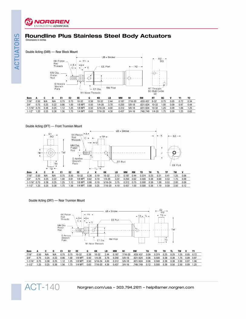
Bore A C D EE E1 E2 G J K KK LB MM N1 RM Y V5/16" 0.38 N/A N/A 10-32 0.61 0.36 0.31 0.36 N/A 5-40 1.64 0.125 3/8-24 .371/.373 0.47 0.037/16" 0.50 N/A N/A 10-32 0.74 0.50 0.38 0.38 0.19 10-32 2.12 0.187 7/16-20 .434/.437 0.72 0.059/16" 0.50 N/A N/A 10-32 0.62 0.62 0.38 0.50 0.19 10-32 2.28 0.187 7/16-20 .434/.437 0.75 0.063/4" 0.50 N/A N/A 1/8 NPT 0.86 0.81 0.50 0.62 0.19 1/4-28 2.97 0.250 5/8-18 .621/.624 0.97 0.097/8" 0.50 N/A N/A 1/8 NPT 0.94 0.94 0.50 0.62 0.19 1/4-28 2.94 0.250 5/8-18 .621/.624 0.97 0.091-1/16" 0.50 N/A † N/A 1/8 NPT 1.12 1.12 0.50 0.88 0.19 5/16-24 3.12 0.312 5/8-18 .621/.624 1.06 0.091-1/4" 0.75 0.25 0.38 1/8 NPT 1.34 1.34 0.63 0.88 0.25 7/16-20 4.00 0.437 3/4-16 .746/.749 1.37 0.091-1/2" 0.75 0.25 0.38 1/8 NPT 1.56 1.56 0.63 0.88 0.25 7/16-20 3.69 0.437 3/4-16 .746/.749 1.25 0.091-3/4" 0.88 0.31 0.44 1/4 NPT 1.84 1.84 0.75 1.25 0.25 1/2-20 4.69 0.500 1-14 1.029/1.032 1.63 0.092" 0.88 0.38 0.50 1/4 NPT 2.08 2.08 0.81 1.25 0.31 1/2-20 4.69 0.625 1-1/4-12 1.372/1.375 1.46 0.122-1/2" 0.88 0.38 0.50 1/4 NPT 2.59 2.59 0.81 1.75 0.31 1/2-20 4.69 0.625 1-3/8-12 1.497/1.500 1.46 0.123" 1.25 0.38 0.63 3/8 NPT 3.12 3.12 1.00 2.00 0.31 5/8-18 5.25 0.750 1-1/2-12 1.622/1.625 1.71 0.19
Double Acting (DAN) — Nose Mount
Bore A C CB CD D E EE FL G KK L LB LH MM N1 N2 RM V XD Y5/16"* 0.38 N/A 0.25 0.125 N/A 0.61 10-32 0.34 0.31 5-40 0.19 2.19 0.39 0.125 3/8-24 3/8-24 .371/.373 0.03 2.03 0.477/16" 0.50 N/A 0.31 0.156 N/A 0.74 10-32 0.44 0.38 10-32 0.25 2.81 0.50 0.187 7/16-20 7/16-20 .434/.437 0.05 2.56 0.729/16"* 0.50 N/A 0.31 0.156 N/A 0.62 10-32 0.38 0.38 10-32 0.25 2.75 0.50 0.187 7/16-20 7/16-20 .434/.437 0.06 2.56 0.753/4" 0.50 N/A 0.38 0.250 N/A 0.86 1/8 NPT 0.62 0.50 1/4-28 0.34 4.03 0.75 0.250 5/8-18 5/8-18 .621/.624 0.09 3.75 0.977/8" 0.50 N/A 0.38 0.250 N/A 0.94 1/8 NPT 0.62 0.50 1/4-28 0.34 3.84 0.75 0.250 5/8-18 5/8-18 .621/.624 0.09 3.56 0.971-1/16" 0.50 0.12 0.38 0.250 0.25 1.12 1/8 NPT 0.62 0.50 5/16-24 0.34 4.12 0.75 0.312 5/8-18 5/8-18 .621/.624 0.09 3.84 1.071-1/4" 0.75 0.25 0.50 0.250 0.38 1.34 1/8 NPT 0.78 0.63 7/16-20 0.41 5.12 0.88 0.437 3/4-16 3/4-16 .746/.749 0.09 4.72 1.371-1/2" 0.75 0.25 0.62 0.375 0.38 1.56 1/8 NPT 0.81 0.63 7/16-20 0.50 4.75 1.00 0.437 3/4-16 3/4-16 .746/.749 0.09 4.38 1.251-3/4" 0.88 0.31 0.62 0.376 0.44 1.84 1/4 NPT 1.12 0.75 1/2-20 0.50 6.25 1.00 0.500 1-14 1-14 1.029/1.032 0.09 5.75 1.632"* 0.88 0.38 0.75 0.375 0.50 2.08 1/4 NPT 1.03 0.81 1/2-20 0.56 6.06 1.63 0.625 1-1/4-12 1-1/4-12 1.372/1.375 0.12 5.62 1.542-1/2"* 0.88 0.38 0.75 0.375 0.50 2.59 1/4 NPT 1.03 0.81 1/2-20 0.56 6.06 1.63 0.625 1-3/8-12 1-3/8-12 1.497/1.500 0.12 5.62 1.473"* 1.25 0.38 0.88 0.500 0.63 3.12 3/8 NPT 1.34 1.00 5/8-18 0.81 7.12 1.90 0.750 1-1/2-12 1-1/2-12 1.622/1.625 0.19 6.50 1.71
Double Acting (DAP) — Pivot Mount
† 1-1/16 bore with SS or PS option, C = 0.12 and D = 0.25. To remove the flats and plain rod stick out, specify NF in the model number.
* Pivot bushing included

ACT-139
ACTUATORSRoundline Plus Stainless Steel Body Actuators
Norgren.com/usa – 303.794.2611 – [email protected]
Dimensions in inches
Bore A C D E EE G K KK LB MM N1 RM V Y1 Y25/16"* 0.38 N/A N/A 0.61 10-32 0.31 0.35 5-40 2.19 0.125 3/8-24 .371/.373 0.03 0.47 0.507/16" 0.50 N/A N/A 0.74 10-32 0.38 0.50 10-32 2.81 0.187 7/16-20 .434/.437 0.05 0.73 0.699/16"* 0.50 N/A N/A 0.62 10-32 0.38 0.44 10-32 2.75 0.187 7/16-20 .434/.437 0.06 0.75 0.573/4" 0.50 N/A N/A 0.86 1/8 NPT 0.50 0.62 1/4-28 4.03 0.250 5/8-18 .621/.624 0.09 0.97 0.907/8" 0.50 N/A N/A 0.94 1/8 NPT 0.50 0.62 1/4-28 3.84 0.250 5/8-18 .621/.624 0.09 0.97 0.901-1/16" 0.50 0.12 0.25 1.12 1/8 NPT 0.50 0.62 5/16-24 4.12 0.312 5/8-18 .621/.624 0.09 1.07 0.901-1/4" 0.75 0.25 0.38 1.34 1/8 NPT 0.63 0.81 7/16-20 5.12 0.437 3/4-16 .746/.749 0.09 1.37 1.181-1/2" 0.75 0.25 0.38 1.56 1/8 NPT 0.63 0.88 7/16-20 4.75 0.437 3/4-16 .746/.749 0.09 1.25 1.181-3/4" 0.88 0.31 0.44 1.84 1/4 NPT 0.75 1.00 1/2-20 6.25 0.500 1-14 1.029/1.032 0.09 1.63 1.622"* 0.88 0.38 0.50 2.08 1/4 NPT 0.81 1.00 1/2-20 6.06 0.625 1-1/4-12 1.372/1.375 0.12 1.46 1.472-1/2"* 0.88 0.38 0.50 2.59 1/4 NPT 0.81 1.00 1/2-20 6.06 0.625 1-3/8-12 1.497/1.500 0.12 1.46 1.473"* 1.25 0.38 0.63 3.12 3/8 NPT 1.00 1.43 5/8-18 7.12 0.750 1-1/2-12 1.622/1.625 0.19 1.71 1.96
Double Acting (DAD) — Double End Mount
Bore A BC C D DB DN EE E1 E2 H J K KK LB MM RM RT SB V Y5/16" 0.38 N/A N/A N/A N/A N/A 10-32 0.50 0.36 N/A N/A N/A 5-40 1.72 0.125 N/A N/A N/A N/A N/A7/16" 0.50 0.75 N/A N/A 8-32 N/A 10-32 0.75 0.50 N/A 0.38 0.19 10-32 2.12 0.187 0.437 8-32 N/A 0.06 N/A3/4" 0.75 1.00 0.25 0.22 1/4-20 0.62 1/8 NPT 1.00 0.81 0.38 0.62 0.19 1/4-28 3.22 0.250 0.625 10-32 #10 0.09 0.501-1/16" 0.75 1.25 0.38 0.25 1/4-20 0.81 1/8 NPT 1.25 1.12 0.62 0.88 0.19 5/16-24 3.75 0.312 0.75 10-32 #10 0.09 0.541-1/2" 1.25 1.75 0.25 0.38 5-16-18 1.12 1/4 NPT 1.75 1.56 0.88 0.88 0.25 7/16-20 4.19 0.437 1.00 1/4-20 1/4 0.13 0.65
Double Acting (DAF) — Front Block Mount
* Pivot bushing included
ACT-140
ACTUATORS Roundline Plus Stainless Steel Body Actuators
Norgren.com/usa – 303.794.2611 – [email protected]
Dimensions in inches
Bore A C D E1 E2 EE G KK LB MM N1 RM RT BC V Y1 Y27/16" 0.50 N/A N/A 0.75 0.75 10-32 0.38 10-32 2.44 0.187 7/16-20 .433/.437 8-32 0.75 0.05 0.72 0.343/4" 0.75 0.25 0.22 0.86 1.00 1/8 NPT 0.50 1/4-28 3.78 0.250 5/8-18 .621/.624 10-32 1.00 0.09 0.97 0.441-1/16" 0.75 0.38 0.25 1.12 1.25 1/8 NPT 0.50 5/16-24 4.00 0.312 5/8-18 .621/.624 10-32 1.25 0.09 1.06 1.251-1/2" 1.25 0.25 0.38 1.56 1.75 1/4 NPT 0.63 7/16-20 4.38 0.437 3/4-16 .746/.749 1/4-20 1.75 0.09 1.25 0.62
Double Acting (DAR) — Rear Block Mount
Bore A C D E1 E2 EE J K KK LB MM RM TD TH TL TP TW V7/16" 0.50 N/A N/A 0.75 0.50 10-32 0.38 0.19 10-32 2.12 0.187 0.44 0.374 0.25 0.31 0.41 1.25 0.063/4" 0.75 0.25 0.22 1.00 0.81 1/8 NPT 0.62 0.19 1/4-28 3.22 0.250 0.62 0.500 0.38 0.69 0.53 1.75 0.091-1/16" 0.75 0.38 0.25 1.25 1.12 1/8 NPT 0.88 0.19 5/16-24 3.75 0.312 0.75 0.500 0.38 1.09 0.53 2.00 0.091-1/2" 1.25 0.25 0.38 1.75 1.56 1/4 NPT 0.88 0.25 7/16-20 4.19 0.437 1.00 0.500 0.38 1.19 0.59 2.50 0.12
Double Acting (DFT) — Front Trunnion Mount
Bore A C D E1 E2 EE G KK LB MM N1 RM TA TD TH TL TW V Y17/16" 0.50 N/A N/A 0.75 0.75 10-32 0.38 10-32 2.44 0.187 7/16-20 .433/.437 0.09 0.374 0.25 0.25 1.25 0.05 0.723/4" 0.75 0.25 0.22 0.86 1.00 1/8 NPT 0.50 1/4-28 3.78 0.250 5/8-18 .621/.624 0.06 0.500 0.38 0.38 1.75 0.09 0.971-1/16" 0.75 0.38 0.25 1.12 1.25 1/8 NPT 0.50 5/16-24 4.00 0.312 5/8-18 .621/.624 0.06 0.500 0.38 0.38 2.00 0.07 1.061-1/2" 1.25 0.25 0.38 1.56 1.75 1/4 NPT 0.63 7/16-20 4.38 0.437 3/4-16 .746/.749 0.12 0.500 0.38 0.50 2.50 0.09 1.25
Double Acting (DRT) — Rear Trunnion Mount

ACT-141
ACTUATORSRoundline Plus Stainless Steel Body Actuators
Norgren.com/usa – 303.794.2611 – [email protected]
Dimensions in inches
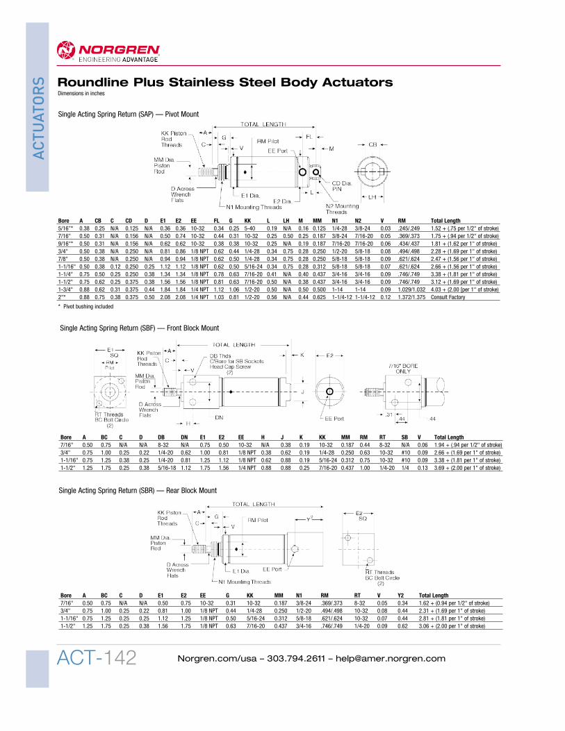
Bore A C D E EE G J K KK MM N1 RM V Total Length5/16" 0.38 N/A N/A 0.36 10-32 0.25 N/A N/A 5-40 0.125 1/4-28 .309/.312 0.03 1.12 + (0.75 per 1/2" of stroke)7/16" 0.50 N/A N/A 0.50 10-32 0.31 0.38 0.19 10-32 0.187 3/8-24 .369/.373 0.05 1.31 + (0.94 per 1/2" of stroke)9/16" 0.50 N/A N/A 0.62 10-32 0.38 0.50 0.19 10-32 0.187 7/16-20 .434/.437 0.06 1.53 + (1.62 per 1" of stroke)3/4" 0.50 N/A N/A 0.81 1/8 NPT 0.44 0.62 0.19 1/4-28 0.250 1/2-20 .494/.498 0.08 1.50 + (1.69 per 1" of stroke)7/8" 0.50 N/A N/A 0.94 1/8 NPT 0.50 0.62 0.19 1/4-28 0.250 5/8-18 .621/.624 0.09 1.84 + (1.56 per 1" of stroke)1-1/16" 0.50 N/A† N/A 1.12 1/8 NPT 0.50 0.88 0.19 5/16-24 0.312 5/8-18 .621/.624 0.07 1.94 + (1.56 per 1" of stroke)1-1/4" 0.75 0.25 0.38 1.34 1/8 NPT 0.63 0.88 0.25 7/16-20 0.437 3/4-16 .746/.749 0.09 2.66 + (1.81 per 1" of stroke)1-1/2" 0.75 0.25 0.38 1.56 1/8 NPT 0.63 0.88 0.25 7/16-20 0.437 3/4-16 .746/.749 0.09 2.44 + (1.69 per 1" of stroke)1-3/4" 0.88 0.31 0.44 1.84 1/4 NPT 0.75 1.25 0.25 1/2-20 0.500 1-14 1.029/1.032 0.09 2.97 + (2.00 per 1" of stroke2" 0.88 0.38 0.50 2.08 1/4 NPT 0.81 1.25 0.31 1/2-20 0.625 1-1/4-12 1.372/1.375 0.12 Consult Factory
Single Acting Spring Return (SAN) — Nose Mount
Bore A C D E EE G KK MM N1 RM V Y ZM7/16" 0.50 N/A N/A 0.74 10-32 0.38 10-32 0.187 7/16-20 .434/.437 0.05 0.72 2.819/16" 0.50 N/A N/A 0.62 10-32 0.38 10-32 0.187 7/16-20 .434/.437 0.06 0.75 2.943/4" 0.50 N/A N/A 0.86 1/8 NPT 0.50 1/4-28 0.250 5/8-18 .621/.624 0.09 0.97 4.007/8" 0.50 N/A N/A 0.94 1/8 NPT 0.50 1/4-28 0.250 5/8-18 .621/.624 0.09 0.97 3.911-1/16" 0.50 0.12 0.25 1.12 1/8 NPT 0.50 5/16-24 0.312 5/8-18 .621/.624 0.09 1.06 4.001-1/4" 0.75 0.25 0.38 1.34 1/8 NPT 0.63 7/16-20 0.437 3/4-16 .746/.749 0.09 1.37 5.561-1/2" 0.75 0.25 0.38 1.56 1/8 NPT 0.63 7/16-20 0.437 3/4-16 .746/.749 0.09 1.25 5.121-3/4" 0.88 0.31 0.44 1.84 1/4 NPT 0.75 1/2-20 0.500 1-14 1.029/1.032 0.09 1.94 6.562" 0.88 0.38 0.50 2.08 1/4 NPT 0.81 1/2-20 0.625 1-1/4-12 1.372/1.375 0.12 1.46 6.562-1/2" 0.88 0.38 0.50 2.59 1/4 NPT 0.81 1/2-20 0.625 1-3/8-12 1.497/1.500 0.12 1.46 6.563" 1.25 0.38 0.63 3.12 3/8 NPT 1.00 5/8-18 0.750 1-1/2-12 1.622/1.625 0.19 1.71 7.31
Double Acting Double Rod End (DRD) — Double End Mount
† 1-1/16 bore with SS or PS option, C = 0.12 and D = 0.25. To remove the flats and plain rod stick out, specify NF in the model number.
ACT-142
ACTUATORS Roundline Plus Stainless Steel Body Actuators
Norgren.com/usa – 303.794.2611 – [email protected]
Dimensions in inches
Bore A BC C D DB DN E1 E2 EE H J K KK MM RM RT SB V Total Length7/16" 0.50 0.75 N/A N/A 8-32 N/A 0.75 0.50 10-32 N/A 0.38 0.19 10-32 0.187 0.44 8-32 N/A 0.06 1.94 + (.94 per 1/2" of stroke)3/4" 0.75 1.00 0.25 0.22 1/4-20 0.62 1.00 0.81 1/8 NPT 0.38 0.62 0.19 1/4-28 0.250 0.63 10-32 #10 0.09 2.66 + (1.69 per 1" of stroke)1-1/16" 0.75 1.25 0.38 0.25 1/4-20 0.81 1.25 1.12 1/8 NPT 0.62 0.88 0.19 5/16-24 0.312 0.75 10-32 #10 0.09 3.38 + (1.81 per 1" of stroke)1-1/2" 1.25 1.75 0.25 0.38 5/16-18 1.12 1.75 1.56 1/4 NPT 0.88 0.88 0.25 7/16-20 0.437 1.00 1/4-20 1/4 0.13 3.69 + (2.00 per 1" of stroke)
Bore A BC C D E1 E2 EE G KK MM N1 RM RT V Y2 Total Length7/16" 0.50 0.75 N/A N/A 0.50 0.75 10-32 0.31 10-32 0.187 3/8-24 .369/.373 8-32 0.05 0.34 1.62 + (0.94 per 1/2" of stroke)3/4" 0.75 1.00 0.25 0.22 0.81 1.00 1/8 NPT 0.44 1/4-28 0.250 1/2-20 .494/.498 10-32 0.08 0.44 2.31 + (1.69 per 1" of stroke)1-1/16" 0.75 1.25 0.25 0.25 1.12 1.25 1/8 NPT 0.50 5/16-24 0.312 5/8-18 .621/.624 10-32 0.07 0.44 2.81 + (1.81 per 1" of stroke)1-1/2" 1.25 1.75 0.25 0.38 1.56 1.75 1/8 NPT 0.63 7/16-20 0.437 3/4-16 .746/.749 1/4-20 0.09 0.62 3.06 + (2.00 per 1" of stroke)
Single Acting Spring Return (SBF) — Front Block Mount
Single Acting Spring Return (SBR) — Rear Block Mount
Bore A CB C CD D E1 E2 EE FL G KK L LH M MM N1 N2 V RM Total Length5/16”* 0.38 0.25 N/A 0.125 N/A 0.36 0.36 10-32 0.34 0.25 5-40 0.19 N/A 0.16 0.125 1/4-28 3/8-24 0.03 .245/.249 1.52 + (.75 per 1/2" of stroke)7/16" 0.50 0.31 N/A 0.156 N/A 0.50 0.74 10-32 0.44 0.31 10-32 0.25 0.50 0.25 0.187 3/8-24 7/16-20 0.05 .369/.373 1.75 + (.94 per 1/2" of stroke)9/16"* 0.50 0.31 N/A 0.156 N/A 0.62 0.62 10-32 0.38 0.38 10-32 0.25 N/A 0.19 0.187 7/16-20 7/16-20 0.06 .434/.437 1.81 + (1.62 per 1" of stroke)3/4" 0.50 0.38 N/A 0.250 N/A 0.81 0.86 1/8 NPT 0.62 0.44 1/4-28 0.34 0.75 0.28 0.250 1/2-20 5/8-18 0.08 .494/.498 2.28 + (1.69 per 1" of stroke)7/8" 0.50 0.38 N/A 0.250 N/A 0.94 0.94 1/8 NPT 0.62 0.50 1/4-28 0.34 0.75 0.28 0.250 5/8-18 5/8-18 0.09 .621/.624 2.47 + (1.56 per 1" of stroke)1-1/16" 0.50 0.38 0.12 0.250 0.25 1.12 1.12 1/8 NPT 0.62 0.50 5/16-24 0.34 0.75 0.28 0.312 5/8-18 5/8-18 0.07 .621/.624 2.66 + (1.56 per 1" of stroke)1-1/4" 0.75 0.50 0.25 0.250 0.38 1.34 1.34 1/8 NPT 0.78 0.63 7/16-20 0.41 N/A 0.40 0.437 3/4-16 3/4-16 0.09 .746/.749 3.38 + (1.81 per 1" of stroke)1-1/2" 0.75 0.62 0.25 0.375 0.38 1.56 1.56 1/8 NPT 0.81 0.63 7/16-20 0.50 N/A 0.38 0.437 3/4-16 3/4-16 0.09 .746/.749 3.12 + (1.69 per 1" of stroke)1-3/4" 0.88 0.62 0.31 0.375 0.44 1.84 1.84 1/4 NPT 1.12 1.06 1/2-20 0.50 N/A 0.50 0.500 1-14 1-14 0.09 1.029/1.032 4.03 + (2.00 [per 1" of stroke)2"* 0.88 0.75 0.38 0.375 0.50 2.08 2.08 1/4 NPT 1.03 0.81 1/2-20 0.56 N/A 0.44 0.625 1-1/4-12 1-1/4-12 0.12 1.372/1.375 Consult Factory
Single Acting Spring Return (SAP) — Pivot Mount
* Pivot bushing included

ACT-143
ACTUATORSRoundline Plus Stainless Steel Body Actuators
Norgren.com/usa – 303.794.2611 – [email protected]
Dimensions in inches
Bore A C D E1 E2 EE G KK MM N1 RM TA TD TH TL TW V Total Length7/16" 0.50 N/A N/A 0.50 0.75 10-32 0.31 10-32 0.187 3/8-24 .370/.375 0.09 0.37 0.25 0.25 1.25 0.05 1.62 + (0.94 per 1/2" of stroke)3/4" 0.75 0.25 0.22 0.81 1.00 1/8 NPT 0.69 1/4-28 0.250 1/2-20 .494/.498 0.06 0.50 0.38 0.38 1.75 0.08 2.31 + (1.69 per 1" of stroke)1-1/16" 0.75 0.25 0.38 1.12 1.25 1/8 NPT 0.75 5/16-24 0.312 5/8-18 .621/.624 0.06 0.50 0.38 0.38 2.00 0.07 2.81 + (1.81 per 1" of stroke)1-1/2" 1.25 0.25 0.38 1.56 1.75 1/4 NPT 0.88 7/16-20 0.437 3/4-16 .746/.749 0.12 0.50 0.38 0.50 2.50 0.06 3.06+ (2.00 per 1" of stroke)
Single Acting Spring Return (STR) — Rear Trunion Mount
Bore A C E EE G J K KK MM (hex) N1 RM V Total Length7/16" 0.50 0.25 0.50 10-32 0.31 0.38 0.19 10-32 0.187 3/8-24 .369/.373 0.05 1.56 + (.94 per 1/2" of stroke)9/16" 0.50 0.25 0.62 10-32 0.38 0.50 0.19 10-32 0.187 7/16-20 .434/.437 0.06 1.78 + (1.62 per 1" of stroke3/4" 0.50 0.25 0.81 1/8 NPT 0.44 0.62 0.19 1/4-28 0.250 1/2-20 .494/.498 0.08 1.75 + (1.69 per 1" of stroke)7/8" 0.50 0.25 0.94 1/8 NPT 0.50 0.62 0.19 1/4-28 0.250 5/8-18 .621/.624 0.09 2.09 + (1.56 per 1" of stroke)1-1/16" 0.50 0.25 1.12 1/8 NPT 0.50 0.88 0.19 5/16-24 0.375 5/8-18 .621/.624 0.07 2.19 + (1.56 per 1" of stroke)1-1/4" 0.88 0.25 1.34 1/8 NPT 0.63 0.88 0.25 7/16-20 0.437 3/4-16 .746/.749 0.09 2.66 + (1.81 per 1" of stroke)1-1/2" 0.88 0.25 1.56 1/8 NPT 0.63 0.88 0.25 7/16-20 0.437 3/4-16 .746/.749 0.09 2.44 + (1.69 per 1" of stroke)1-3/4" 0.88 0.38 1.84 1/4 NPT 0.74 1.25 0.25 1/2-20 0.500 1-14 1.029/1.032 0.09 3.03 + (2.00 per 1" of stroke)
Single Acting Non-Rotating (NRN) — Nose Mount
Bore A C D E1 E2 EE J K KK MM RM TD TH TL TW V Total Length7/16" 0.50 N/A N/A 0.75 0.50 10-32 0.38 0.19 10-32 0.187 0.44 0.37 0.25 0.31 1.25 0.05 1.94 + (0.94 per 1/2" of stroke)3/4" 0.75 0.25 0.22 1.00 0.81 1/8 NPT 0.62 0.19 1/4-28 0.250 0.62 0.50 0.38 0.69 1.75 0.09 2.66 + (1.69 per 1" of stroke)1-1/16" 0.75 0.25 0.25 1.25 1.12 1/8 NPT 0.88 0.19 5/16-24 0.312 0.75 0.50 0.38 0.97 2.00 0.09 3.38 + (1.81 per 1" of stroke)1-1/2" 1.25 0.25 0.38 1.75 1.56 1/4 NPT 0.88 0.25 7/16-20 0.437 1.00 0.50 0.38 1.19 2.50 0.12 3.69 + (2.00 per 1" of stroke)
Single Acting Spring Return (STF) — Front Trunnion Mount

ACT-144
ACTUATORS Roundline Plus Stainless Steel Body Actuators
Norgren.com/usa – 303.794.2611 – [email protected]
Dimensions in inches
Bore A C D E1 E2 EE G KK MM N1 RM V Y Total Length5/16" 0.38 N/A N/A 0.61 0.36 10-32 0.31 5-40 0.125 3/8-24 .371/.373 0.03 0.47 1.49 + (1.25 per 1/2" of stroke)7/16" 0.50 N/A N/A 0.74 0.50 10-32 0.38 10-32 0.187 7/16-20 .434/.437 0.05 0.72 1.94 + (1.44 per 1/2" of stroke)9/16" 0.50 N/A N/A 0.62 0.62 10-32 0.38 10-32 0.187 7/16-20 .434/.437 0.06 0.75 2.00 + (2.62 per 1" of stroke)3/4" 0.50 N/A N/A 0.86 0.81 1/8 NPT 0.50 1/4-28 0.250 5/8-18 .621/.624 0.09 0.97 2.31 + (2.69 per 1" of stroke)7/8" 0.50 N/A N/A 0.94 0.94 1/8 NPT 0.50 1/4-28 0.250 5/8-18 .621/.624 0.09 0.97 2.31 + (2.56 per 1" of stroke)1-1/16" 0.50 0.12 0.25 1.12 1.12 1/8 NPT 0.50 5/16-24 0.312 5/8-18 .621/.624 0.09 1.06 2.62 + (2.81 per 1" of stroke)1-1/4" 0.75 0.25 0.38 1.34 1.34 1/8 NPT 0.63 7/16-20 0.437 3/4-16 .746/.749 0.09 1.37 3.47 + (2.81 per 1" of stroke)1-1/2" 1.25 0.25 0.38 1.56 1.56 1/8 NPT 0.63 7/16-20 0.437 3/4-16 .746/.749 0.09 1.25 3.19 + (3.00 per 1" of stroke)1-3/4" 0.88 0.31 0.44 1.84 1.84 1/4 NPT 0.75 1/2-20 0.500 1-14 1.029/1.032 0.09 1.62 4.03 + (3.00 per 1" of stroke)2" 0.88 0.38 0.50 2.08 2.08 1/4 NPT 0.81 1/2-20 0.625 1-1/4-12 1.372/1.375 0.12 1.46 Consult Factory
Reverse Acting Spring Extend (RAN) — Nose Mount
Bore A C CB CD E1 E2 EE FL G KK L LH M MM (hex) N1 N2 RM V Total Length7/16" 0.50 0.25 0.31 0.156 0.50 0.74 10-32 0.44 0.31 10-32 0.25 0.50 0.25 0.187 3/8-24 7/16-20 .369/.373 0.05 2.00 + (.94 per 1/2" of stroke)9/16"* 0.50 0.25 0.31 0.156 0.62 0.62 10-32 0.38 0.38 10-32 0.25 N/A 0.19 0.187 7/16-20 7/16-20 .434/.437 0.06 2.06 + (1.62 per 1" of stroke)3/4" 0.50 0.25 0.38 0.250 0.81 0.86 1/8 NPT 0.62 0.44 1/4-28 0.34 0.75 0.28 0.250 1/2-20 5/8-18 .494/.498 0.08 2.53 + (1.69 per 1" of stroke)7/8" 0.50 0.25 0.38 0.250 0.94 0.94 1/8 NPT 0.62 0.50 1/4-28 0.34 0.75 0.28 0.250 5/8-18 5/8-18 .621/.624 0.09 2.72 + (1.56 per 1" of stroke)1-1/16" 0.50 0.25 0.38 0.250 1.12 1.12 1/8 NPT 0.62 0.50 5/16-24 0.34 0.75 0.28 0.375 5/8-18 5/8-18 .621/.624 0.07 2.78 + (1.56 per 1" of stroke)1-1/4" 0.88 0.25 0.50 0.250 1.34 1.34 1/8 NPT 0.78 0.63 7/16-20 0.41 0.88 0.40 0.437 3/4-16 3/4-16 .746/.749 0.09 3.38 + (1.81 per 1" of stroke)1-1/2" 0.88 0.38 0.62 0.375 1.56 1.56 1/8 NPT 0.81 0.63 7/16-20 0.50 1.00 0.37 0.437 3/4-16 3/4-16 .746/.749 0.09 3.25 + (1.69 per 1" of stroke)1-3/4" 0.88 0.38 0.62 0.375 1.84 1.84 1/4 NPT 1.12 0.74 1/2-20 0.50 N/A 0.50 0.500 1-14 1-14 1.029/1.032 0.09 4.09 + (2.00 per 1" of stroke)
Single Acting Non-Rotating (NRP) — Pivot Mount
* Pivot bushing included

ACT-145
ACTUATORSRoundline Plus Stainless Steel Body Actuators
Norgren.com/usa – 303.794.2611 – [email protected]
Dimensions in inches
Bore A C D DB DN SB E1 E2 EE H KK L MM RM RT BC V Y Total Length3/4" 0.75 0.25 0.22 1/4-20 0.63 10-32 1.00 0.81 1/8 NPT 0.38 1/4-28 1.09 0.250 0.62 10-32 1.00 0.09 0.5 2.56 + (2.69 per 1" of stroke)1-1/16" 0.75 0.25 0.38 1/4-20 0.81 10-32 1.25 1.12 1/8 NPT 0.62 5/16-24 1.22 0.312 0.75 10.32 1.25 0.07 0.54 3.12 + (2.81 per 1" of stroke)1-1/2" 1.25 0.25 0.38 5/16-18 1.12 0.25 1.75 1.56 1/4 NPT 0.88 7/16-20 1.63 0.437 1.00 1/4-20 1.75 0.12 0.65 3.69 + (3.00 per 1" of stroke)
Reverse Acting Spring (RAF) — Front Block Mount
Bore A C CB CD D EE E G KK L LH MM M N1 N2 RM V Y Total Length5/16"* 0.38 N/A 0.25 0.125 N/A 10-32 0.61 0.31 5-40 0.19 N/A 0.125 0.16 3/8-24 3/8-24 .371/.373 0.03 0.47 1.88 + (1.25 per 1/2" of stroke)7/16" 0.50 N/A 0.31 0.156 N/A 10-32 0.74 0.38 10-32 0.25 0.50 0.187 0.25 7/16-20 7/16-20 .434/.437 0.05 0.72 2.38 + (1.44 per 1/2" of stroke)9/16"* 0.50 N/A 0.31 0.156 N/A 10-32 0.62 0.38 10-32 0.25 0.50 0.187 0.19 7/16-20 7/16-20 .434/.437 0.06 0.75 2.28 + (2.62 per 1" of stroke)3/4" 0.50 N/A 0.38 0.250 N/A 1/8 NPT 0.86 0.50 1/4-28 0.34 0.75 0.250 0.28 5/8-18 –– .621/.624 0.09 0.97 2.44 + (2.69 per 1" of stroke)7/8" 0.50 N/A 0.38 0.250 N/A 1/8 NPT 0.94 0.50 1/4-28 0.34 0.75 0.250 0.28 5/8-18 –– .621/.624 0.09 0.97 2.62 + (2.56 per 1" of stroke)1-1/16" 0.50 0.12 0.38 0.250 0.25 1/8 NPT 1.12 0.50 5/16-24 0.34 0.75 0.312 0.28 5/8-18 –– .621/.624 0.09 1.06 2.78 + (2.81 per 1" of stroke)1-1/4" 0.75 0.25 0.50 0.250 0.38 1/8 NPT 1.34 0.63 7/16-20 0.44 0.88 0.437 0.38 3/4-16 3/4-16 .746/.749 0.09 1.37 3.78 + (2.81 per 1" of stroke)1-1/2" 1.25 0.25 0.62 0.375 0.38 1/8 NPT 1.56 0.63 7/16-20 0.50 1.00 0.437 0.38 3/4-16 3/4-16 .746/.749 0.09 1.25 3.88 + (3.00 per 1" of stroke)2"* 0.88 0.38 0.75 0.375 0.50 1/4 NPT 2.08 0.81 1/2-20 0.56 1.63 0.625 0.44 1-1/4-12 1-1/4-12 1.372/1.375 0.12 1.46 Consult Factory
Reverse Acting Spring Extend (RAP) — Pivot Mount
* Pivot bushing included

ACT-146
ACTUATORS Roundline Plus Stainless Steel Body Actuators
Norgren.com/usa – 303.794.2611 – [email protected]
Bore Part Number A B BA CD DD E F FL G J M7/16", 9/16" PB-1 0.50 0.28 0.50 0.16 0.19 0.75 0.06 0.77 0.12 0.56 0.203/4", 7/8", PB-2 0.81 0.44 0.75 0.25 0.27 1.12 0.12 1.19 0.19 0.88 0.311-1/16", 1-1/4"1-1/2" PB-3 1.00 0.62 1.00 0.38 0.27 1.50 0.12 1.75 0.25 1.38 0.381-3/4",2", 2-1/2" PB-4 1.13 0.68 1.00 0.38 0.26 1.50 0.25 1.75 0.25 1.38 0.383" PB-5 1.44 0.88 1.25 0.50 0.27 1.75 0.25 2.25 0.25 1.75 0.50
Bore Part Number CA CB dia. CD CE CH KK L LH N5/16" RC-0 0.13 0.13 0.56 0.44 0.31 5-40 0.38 0.5 0.167/16", 9/16" RC-1 0.19 0.19 0.94 0.75 0.38 10-32 0.56 0.66 0.123/4", 7/8" RC-2 0.25 0.25 1.19 0.94 0.50 1/4-28 0.68 0.85 0.161-1/16" RC-3 0.25 0.25 1.19 0.94 0.50 5/16-24 0.69 0.85 0.191-1/4", 1-1/2" RC-4 0.38 0.38 1.69 1.31 0.75 7/16-20 0.94 1.12 0.251-3/4, 2", 2-1/2" RC-5 0.38 0.38 1.69 1.31 0.75 1/2-20 0.94 1.12 0.313" RC-6 0.50 0.50 2.75 2.25 1 5/8-18 1.5 1.41 0.38
Pivot Bracket (without pin)
Rod Clevis(Includes Pin & Jam Nut)
• All accessories are clear zinc plated carbon steel
PB-0 (5/16" bore only) (includes pin)
Dimensions in inches
Bore Part Number5/16 PB-07/16", 9/16" PB-1K3/4", 7/8", PB-2K1-1/16", 1-1/4"1-1/2" PB-3K1-3/4",2", 2-1/2" PB-4K3" PB-5K
Pivot Bracket (with pin)
Bore A C D E1 E2 EE G KK MM N1 RM RT BC V Y Total Length3/4" 0.75 0.25 0.22 0.86 1.00 1/8 NPT 0.50 1/4-28 0.250 5/8-18 .621/.624 10-32 1.00 0.09 0.97 3.22 + (2.69 per 1" of stroke)1-1/16" 0.75 0.25 0.25 1.12 1.25 1/8 NPT 0.50 5/16-24 0.312 5/8-18 .621/.624 10-32 1.25 0.09 1.06 3.53 + (2.81 per 1" of stroke)1-1/2" 1.25 0.25 0.38 1.56 1.75 1/4 NPT 0.62 7/16-20 0.437 3/4-16 .746/.749 1/4-20 1.75 0.09 1.25 3.88 + (3.00 per 1" of stroke)
Reverse Acting Spring (RAR) — Rear Block Mount

ACT-147
ACTUATORSRoundline Plus Stainless Steel Body Actuators
Norgren.com/usa – 303.794.2611 – [email protected]
Bore Part Number A B BA C CD DD E F FL J
5/16"(S) FB-0S 0.38 0.25 0.75 0.13 0.25 0.13 1.00 0.06 0.44 0.755/16"(D) FB-0D 0.38 0.25 0.75 0.13 0.38 0.13 1.00 0.06 0.44 0.757/16"(S) FB-1 0.62 0.31 1.00 0.12 0.38 0.19 1.38 0.07 0.56 0.887/16"(D), 9/16"(S/D) FB-2 0.69 0.38 1.00 0.12 0.44 0.19 1.38 0.09 0.56 0.833/4"(S) FB-3 0.75 0.44 1.25 0.19 0.50 0.19 1.62 0.10 0.69 1.093/4"(D), 7/8"(S/D), 1-1/16"(S/D) FB-4 1.00 0.56 1.50 0.25 0.62 0.27 1.88 0.12 0.81 1.38
1-1/4"(S/D), 1-1/2"(S/D) FB-5 1.50 0.75 1.88 0.62 0.75 0.28 2.50 0.12 1.00 1.751-3/4"(S/D) FB-5A 1.50 0.88 2.25 0.75 1.03 0.34 3.00 0.19 1.25 2.132"(S/D) FB-6 1.62 1.00 2.25 0.62 1.38 0.34 3.12 0.25 1.50 2.502-1/2"(D) FB-7 1.62 1.00 2.88 0.75 1.50 0.34 3.75 0.25 1.75 3.003"(D) FB-8 1.62 1.00 3.50 0.89 1.63 0.34 4.38 0.26 1.89 3.14S = Single Acting Models D = Double Acting Models S/D = Single and Double Acting Models
Foot Bracket
Bore Part number A B BA CD DD E F FL G J M7/16" PB-4 1.13 0.69 1.00 0.38 0.27 1.50 0.25 1.75 0.25 1.38 0.383/4", 1-1/16", 1-1/2" TB-1 1.13 0.69 1.00 0.50 0.27 1.50 0.25 1.75 0.25 1.38 0.38
Trunnion Bracket
Mounting Nut
Single Acting Spring Return ModelsBore Part
Number N E T5/16" MN-0 1/4-28 0.44 0.167/16" MN-1 3/8-24 0.56 0.229/16" MN-2 7/16-20 0.69 0.253/4" MN-3 1/2-20 0.75 0.317/8", 1-1/16" MN-4 5/8-18 0.94 0.381-1/4", 1-1/2" MN-5 3/4-16 1.12 0.421-3/4" MN-5A 1-14 1.50 0.552" MN-6 1-1/4-12 1.88 0.50
Single Acting Spring Extend & Double Acting ModelsBore Part
Number N E T5/16" MN-1 3/8-24 0.56 0.227/16", 9/16" MN-2 7/16-20 0.69 0.253/4", 7/8", 1-1/16" MN-4 5/8-18 0.94 0.381-1/4", 1-1/2" MN-5 3/4-16 1.12 0.421-3/4" MN-5A 1-14 1.50 0.552" MN-6 1-1/4-12 1.88 0.502-1/2" MN-7 1-3/8-12 1.88 0.503" MN-8 1-1/2-12 2.25 0.50
Dimensions in inches

ACT-148
ACTUATORS RPHD Series Magnetic Roundline
Plus Stainless Steel Body CylindersDouble acting9/16" - 2-1/2" bores
Norgren.com/usa – 303.794.2611 – [email protected]
Technical DataMedium:Filtered, lubricated or non-lubricated, compressed air
Maximum OperatingPressure:250 psig (17.2 bar)
Temperature Range*:Standard nitrile seals:-20°F to 200°F (-29°C to 93°C)Viton / High temp seals:-20°F to 400°F (-29°C to 205°C)* With dew point of supply air less than airtemperature below 36°F (2°C).
Lubrication:All RPHD cylinders are pre-lubricated during assembly with aTeflon® based grease for non-lube service and long life.
Materials:Cylinder Body:
304 Stainless SteelHead and Cap:
Aluminum alloyPiston Rods:
300 series, chrome platedstainless steelRod Bearings:
Oil impregnated sintered bronzePiston:
Aluminum Alloy or stainless steelRod & Piston Seals: NitrilePivot bracket, rod clevis, footbracket, mounting nut:Bright zinc plated carbon steel
Options selector RPHD 106 x 3.250 - DAN - M2
Series SubstituteRPHD Series RPHDMagnetic
Bore Substitute9/16" 0563/4" 0751-1/16" 1061-1/4" 1251-1/2" 1501-3/4" 1752" 2002-1/2" 250
StrokeIncrements of 1/16"up to 36"
Mounting Options Substitute(All models are double acting)Nose DANDouble End (with pivot bushing) DADDouble Rod End DRD
Options SubstituteViton / High Temp seals HT*Switch rail and position M1, M2, M3, M4Side Ported end cap PC(DAN mount only)Alternate port location PL(__)Plain rod end PR**Rod extension over std. RX(_)(specify additional length)Thread extension over std. TX(_)(specify additional length)Bumpers both ends UB*
*Viton seals and Bumpers are available incombination; however, the temperature ratingof the cylinder is limited to the maximumtemperature rating of the bumpers.Note: The magnetic field could becompromised with temperatures in excess of 200°F.** PR Rod end will not have threads, but willmaintian the standard “A” dimension.

ACT-149
ACTUATORSRPHD Series Magnetic Roundline
Plus Stainless Steel Body Cylinders
Norgren.com/usa – 303.794.2611 – [email protected]
Pivot Bushing (DAD model): Sintered bronze pivot bushing
Piston Seals: Lip-Type nitrile piston seals are wearcompensating for long life.
Magnetic Band: On piston for position sensing with externalswitches.
Piston: Solid aluminum piston is strong, yet lightweight for lowinertia. Stainless steel in double rod models.
Cylinder Tube: 304 Stainless steel cylinder body ensuressmooth performance and outstanding life cycle.
Rod Seal: Lip-Type nitrile, pressure energized and wearcompensating.
Head and Cap: Solid aluminum alloy for strength and durability.
Bearing: Oil impregnated, sinterend bonze provides exceptionalrod support, and optimal cycle life.
Piston Rod: Chrome plated 300 series stainless steel forsmooth operation and corrosion resistance.
8
96
7
421
5
3
1
2
3
4
5
6
7
8
9
The RPHD Series cylinders provide:» Roundline Plus cylinder features and construction» More robust mounting threads
» Larger rod diameters » Longer rod bearing for long life» A magnet for position sensing with external reed
switches » Preferred mounting styles for versatility and ease of
installation
Switch rail can bemounted in 4 positions M1 = position 1M2 = position 2M3 = position 3M4 = position 4
Switches orderedseparately
Option PC - Side Ported End CapCap end port will be on the side of the end cap and in line with the head end port. Overall lengthof the cylinder will increase with this option. See dimensional tables for overall length information.
Option PL(__)Alternate Port Location Designate location on head andcap respectively. For Example:L(12) = Head port location #1, andcap port location #2.
Option UB -Bumpers both endsNOTE: Bumpers willincrease the overall lengthof the cylinder. See chart forlength adders.
Bore UB option length adder
9/16" 0.125"3/4" 0.250"1-1/16" 0.250"1-1/4" 0.250"1-1/2" 0.250"1-3/4" 0.250"2" 0.250"2-1/2" 0.250"
Options
Switch Rail Mounting Position
M2
M3
M4
M1

ACT-150
ACTUATORS RPHD Series Magnetic Roundline
Plus Stainless Steel Body Cylinders
Norgren.com/usa – 303.794.2611 – [email protected]
RPHD Double Acting, Double End Mount (DAD)
Bore Code A C CB CD D E EE FL G KK L LB MM N1 RM V XD Y9/16" (056) 0.50 N/A 0.31 0.16 N/A 0.61 #10-32 0.38 0.38 #10-32 0.25 3.00 0.187 7/16-20 .434/.437 0.06 2.81 0.753/4" (075) 0.59 0.25 0.44 0.22 0.25 1.13 1/8 NPT 0.63 0.75 1/4-28 0.34 4.59 0.312 5/8-18 .621/.624 0.06 4.31 1.281-1/16" (106) 0.63 0.25 0.50 0.25 0.31 1.13 1/8 NPT 0.72 0.88 5/16-24 0.38 4.78 0.375 3/4-16 .746/.749 0.06 4.47 1.441-1/4" (125) 0.75 0.25 0.63 0.31 0.38 1.34 1/8 NPT 0.81 1.00 3/8-24 0.47 5.00 0.437 7/8-14 .871/.874 0.08 4.63 1.561-1/2" (150) 0.88 0.25 0.69 0.38 0.44 1.56 1/4 NPT 0.97 1.06 7/16-20 0.56 5.53 0.500 1-14 .996/.999 0.09 5.06 1.661-3/4" (175) 1.00 0.31 0.75 0.38 0.50 1.84 1/4 NPT 0.97 1.25 1/2-20 0.56 5.97 0.562 1-1/8-12 1.121/1.124 0.09 5.50 1.912" (200) 1.00 0.31 0.86 0.44 0.50 2.08 1/4 NPT 1.09 1.31 1/2-20 0.66 6.63 0.625 1-1/4-12 1.246/1.249 0.11 6.13 2.032-1/2" (250) 1.25 0.38 1.00 0.50 0.63 2.63 3/8 NPT 1.31 1.44 5/8-18 0.69 7.41 0.750 1-3/8-12 1.371/1.374 0.13 6.78 2.22
RPHD Double acting nose mount (DAN)
Bore Code A C D EE E1 E2 G J K KK LB MM N1 RM V Y9/16" (056) 0.50 N/A N/A #10-32 0.61 0.61 0.38 0.50 0.19 #10-32 2.53 0.187 7/16-20 .434/.437 0.06 0.753/4" (075) 0.59 0.25 0.25 1/8 NPT 1.13 0.81 0.75 0.63 0.19 1/4-28 3.53 0.312 5/8-18 .621/.624 0.06 1.281-1/16" (106) 0.63 0.25 0.31 1/8 NPT 1.13 1.13 0.88 0.88 0.19 5/16-24 3.78 0.375 3/4-16 .746/.749 0.06 1.441-1/4" (125) 0.75 0.25 0.38 1/8 NPT 1.34 1.34 1.00 0.88 0.25 3/8-24 3.91 0.437 7/8-14 .871/.874 0.08 1.561-1/2" (150) 0.88 0.25 0.44 1/4 NPT 1.56 1.56 1.06 0.88 0.25 7/16-20 4.13 0.500 1-14 .996/.999 0.09 1.661-3/4" (175) 1.00 0.31 0.50 1/4 NPT 1.84 1.84 1.25 1.25 0.25 1/2-20 4.63 0.562 1-1/8-12 1.121/1.124 0.09 1.912" (200) 1.00 0.31 0.50 1/4 NPT 2.08 2.08 1.31 1.25 0.31 1/2-20 5.09 0.625 1-1/4-12 1.246/1.249 0.11 2.032-1/2" (250) 1.25 0.38 0.63 3/8 NPT 2.63 2.63 1.44 1.75 0.31 5/8-18 5.41 0.750 1-3/8-12 1.371/1.374 0.13 2.22
RPHD DAN w/PC side ported end cap option
Bore Code A C D E EE G KK LB MM N1 RM V Y Z9/16" (056) 0.50 N/A N/A 0.61 #10-32 0.38 #10-32 2.56 0.187 7/16-20 .434/.437 0.06 0.75 0.133/4" (075) 0.59 0.25 0.25 1.13 1/8 NPT 0.75 1/4-28 3.97 0.312 5/8-18 .621/.624 0.06 1.28 0.281-1/16" (106) 0.63 0.25 0.31 1.13 1/8 NPT 0.88 5/16-24 4.09 0.375 3/4-16 .746/.749 0.06 1.44 0.341-1/4" (125) 0.75 0.25 0.38 1.34 1/8 NPT 1.00 3/8-24 4.16 0.437 7/8-14 .871/.874 0.08 1.56 0.341-1/2" (150) 0.88 0.25 0.44 1.56 1/4 NPT 1.06 7/16-20 4.50 0.500 1-14 .996/.999 0.09 1.66 0.411-3/4" (175) 1.00 0.31 0.50 1.84 1/4 NPT 1.25 1/2-20 4.94 0.562 1-1/8-12 1.121/1.124 0.09 1.91 0.412" (200) 1.00 0.31 0.50 2.08 1/4 NPT 1.31 1/2-20 5.47 0.625 1-1/4-12 1.246/1.249 0.11 2.03 0.442-1/2" (250) 1.25 0.38 0.63 2.63 3/8 NPT 1.44 5/8-18 6.09 0.750 1-3/8-12 1.371/1.374 0.13 2.22 0.63

ACT-151
ACTUATORSRPHD Series Magnetic Roundline
Plus Stainless Steel Body Cylinders
Norgren.com/usa – 303.794.2611 – [email protected]
RPHD Pivot Bracket
RPHD Double Acting, Double Rod End (DRD)
Bore Code A C D E EE G KK LB MM N1 RM V Y ZM9/16" (056) 0.50 N/A N/A 0.61 #10-32 0.38 #10-32 3.19 0.187 7/16-20 .434/.437 0.06 0.75 3.193/4" (075) 0.59 0.25 0.25 1.13 1/8 NPT 0.75 1/4-28 4.41 0.312 5/8-18 .621/.624 0.06 1.28 4.911-1/16" (106) 0.63 0.25 0.31 1.13 1/8 NPT 0.88 5/16-24 4.69 0.375 3/4-16 .746/.749 0.06 1.44 5.191-1/4" (125) 0.75 0.25 0.38 1.34 1/8 NPT 1.00 3/8-24 4.88 0.437 7/8-14 .871/.874 0.08 1.56 5.381-1/2" (150) 0.88 0.25 0.44 1.56 1/4 NPT 1.06 7/16-20 5.25 0.500 1-14 .996/.999 0.09 1.66 5.751-3/4" (175) 1.00 0.31 0.50 1.84 1/4 NPT 1.25 1/2-20 5.81 0.562 1-1/8-12 1.121/1.124 0.09 1.91 6.442" (200) 1.00 0.31 0.50 2.08 1/4 NPT 1.31 1/2-20 6.50 0.625 1-1/4-12 1.246/1.249 0.11 2.03 7.132-1/2" (250) 1.25 0.38 0.63 2.63 3/8 NPT 1.44 5/8-18 7.00 0.750 1-3/8-12 1.371/1.374 0.13 2.22 7.75
Bore Code Part Number A B BA CD DD E F FL G J M PA PB9/16" (056) PB-1K 0.50 0.28 0.50 0.16 0.20 0.75 0.06 0.77 0.13 0.56 0.20 0.34 0.633/4" (075) PB-52 0.81 0.50 0.56 0.22 0.28 1.06 0.12 1.03 0.25 0.81 0.22 0.44 0.881-1/16" (106) PB-53 0.81 0.50 0.56 0.25 0.28 1.06 0.12 1.06 0.25 0.81 0.25 0.50 0.941-1/4" (125) PB-54 0.88 0.56 0.81 0.31 0.28 1.31 0.16 1.31 0.25 1.00 0.31 0.63 1.191-1/2" (150) PB-55 1.00 0.63 1.00 0.38 0.28 1.50 0.19 1.50 0.25 1.13 0.38 0.69 1.441-3/4" (175) PB-56 1.13 0.69 1.00 0.38 0.34 1.63 0.19 1.63 0.31 1.25 0.38 0.75 1.442" (200) PB-57 1.19 0.75 1.19 0.44 0.34 1.81 0.25 1.81 0.31 1.38 0.44 0.88 1.692-1/2" (250) PB-58 1.38 0.88 1.38 0.50 0.41 2.13 0.25 2.13 0.38 1.63 0.50 1.00 2.22
RPHD Mounting Nut
Bore Code Part Number E N T9/16" (056) MN-2 0.69 7/16-20 0.253/4" (075) MN-4 0.94 5/8-18 0.381-1/16" (106) MN-5 1.13 3/4-16 0.421-1/4" (125) MN-54 1.31 7/8-14 0.511-1/2" (150) MN-5A 1.50 1-14 0.551-3/4" (175) MN-56 1.69 1-1/8-12 0.642" (200) MN-6 1.88 1-1/4-12 0.502-1/2" (250) MN-7 2.25 1-3/8-12 0.50
RPHD Rod Clevis
Bore Code Part Number CA CB CD CE CH KK L LH N9/16" (056) RC-1 0.19 0.19 0.94 0.75 0.38 #10-32 0.56 0.66 0.133/4" (075) RC-52 0.22 0.22 1.44 1.19 0.44 1/4-28 0.75 0.63 0.161-1/16" (106) RC-53 0.25 0.25 1.44 1.19 0.50 5/16-24 0.75 0.69 0.201-1/4" (125) RC-54 0.31 0.31 1.69 1.38 0.63 3/8-24 0.94 0.88 0.231-1/2" (150) RC-55 0.38 0.38 2.00 1.63 0.75 7/16-20 1.13 1.03 0.261-3/4" (175) RC-56 0.38 0.38 2.13 1.75 0.75 1/2-20 1.13 1.03 0.322" (200) RC-57 0.44 0.44 2.31 1.88 0.88 1/2-20 1.31 1.14 0.322-1/2" (250) RC-6 0.50 0.50 2.75 2.25 1.00 5/8-18 1.50 1.41 0.39
Bore Code Part Number A B BA C CD DD E F FL J9/16" (056) FB-2 0.69 0.38 1.00 0.13 0.44 0.20 1.38 0.09 0.56 0.833/4" (075) FB-4 1.00 0.56 1.50 0.25 0.63 0.28 1.88 0.12 0.81 1.381-1/16" (106) FB-53 0.94 0.53 1.38 0.23 0.75 0.28 1.88 0.12 0.81 1.441-1/4" (125) FB-54 1.16 0.66 1.56 0.31 0.88 0.28 2.13 0.16 1.00 1.751-1/2" (150) FB-55 1.31 0.75 1.81 0.37 1.00 0.28 2.38 0.19 1.13 2.001-3/4" (175) FB-56 1.44 0.81 2.13 0.37 1.13 0.34 2.75 0.19 1.25 2.192" (200) FB-57 1.59 0.91 2.38 0.43 1.25 0.34 3.00 0.22 1.38 2.442-1/2" (250) FB-58 1.88 1.06 3.00 0.50 1.38 0.41 3.75 0.25 1.63 2.81
RPHD Foot Bracket
RPHD Mounting Accessories

ACT-152
ACTUATORS
Norgren.com/usa – 303.794.2611 – [email protected]
RPD 106 x 3.250 - DAN - PS
RPD Series Delrin® End CapRoundline Plus Stainless Steel Body Actuators 9/16" to 2" boreDouble acting pneumatic actuators
Delrin Acetal Resin end capcylinders for washdown, andcorrosive environmentapplicationTechnical dataMedium: Filtered, lubricated or non-lubricated, compressed airMaximum OperatingPressure:
125 psig (8.6 bar)Temperature Range:Standard Nitrile Seals: 32° to 160°F (0°C to 72°C)Lubrication:All RPD cylinders are pre-lubricated during assembly with aTeflon® based grease for non-lube service and long life. MaterialsCylinder Body:
304 Series stainless steelHead and Cap:
Delrin Acetal ResinPiston Rod:
300 Series chrome plated stainless steel
Piston: Anodized aluminum alloy or stainless steel
Rod & Piston Seals: NitrileMounting Accessories: 300 Series
stainless steel
Options selector
Bore Size9/16" 0563/4" 0751-1/16" 1061-1/2" 1502" 200
SeriesRPD Series Delrin end cap RPDRPD Series Delrin with *ERPDEcology Seals** Ecology version not available on
9/16" bore RPD cylinder
StrokeIncrements of 1/16" up to 36"
Mounting Options (all models are double acting)
Nose DANDouble End (with pivot hole) DADDouble Rod End DRD
Additional OptionsAlternate female thread FT (_)(Specify thread type)Viton seals HT**Switch rail and position M1, M2,
M3, M4Side ported end cap PC(DAN mount only)Alternate port location PL(_)Plain rod end PRMagnetic piston PSRod extension over std. RX(_)(specify additional length)Rod wiper RW†Alternate male thread TM (_)(Specify thread type)Thread extension over std. TX(_)(specify additional length)Bumper both ends UB
** Viton seals are for chemical compatibility applications, and are not available in Ecology 1-1/16" bore
† Rod wiper not available on 9/16" bores
Delrin® is a registered trademark of E.I. Du Pont deNemours and Company for its brand of acetal resin.

ACT-153
ACTUATORSRPD Series Delrin® End Cap
Norgren.com/usa – 303.794.2611 – [email protected]
Head and Cap: Delrin® (acetal resin)
Piston Rod: Chrome plated stainless steel
Tube: Stainless steel
Piston: Anodized aluminum (stainless steel on 9/16" bore DRD model)
Piston Seals: Nitrile (Viton® optional)
Optional magnet on piston for position sensing
1
1
23
4
6
6
5
1
2
3
4
5
RPD Series Delrin® End CapRoundline Plus Stainless Steel Body Actuators
The Norgren RPD Series Cylinder utilizes a stainless steel body, a stainless steel rod, and Delrin® (acetal resin) end caps for corrosion resistance. Thiscylinder is designed to endure a variety of environmental conditions. The RPD Series construction provides resistance to moisture, various solvents, andmany other neutral chemicals. The Norgren RPD Series is ideal in corrosive environment applications.
Additionally, the Norgren RPD Series Cylinder is the only Delrin® end cap cylinder in the industry to offer the patented impact dampening Ecology SealTechnology. The Ecology Seal option, used in conjuction with a fixed cushion, eliminates the bacteria-collecting cushionscrew orifice found in competing adjustable cushion model cylinders.
Delrin® is a registered trademark of E.I. Du Pont de Nemours and Company for its brand of acetal resin.For detailed technical specifications on the properties of Delrin®, please contact DuPont (www.dupont.com).

ACT-154
ACTUATORS RPD Series Delrin® End Cap
Norgren.com/usa – 303.794.2611 – [email protected]
LBEcology LB
Bore A C D E EE G J K KK LB or PC Bumpers MM N1 RM V Y9/16" (056) 0.50 -- -- 0.61 #10-32 0.38 0.50 0.19 #10-32 2.28 -- 2.41 0.19 7/16-20 .434/.437 0.06 0.383/4" (075) 0.50 -- -- 0.81 1/8 NPT 0.50 0.63 0.19 1/4-28 2.97 3.41 2.97 0.25 5/8-18 .621/.624 0.09 0.471-1/16" (106) 0.50 0.13 0.25 1.13 1/8 NPT 0.50 0.88 0.19 5/16-24 3.25 3.50 3.38 0.31 5/8-18 .621/.624 0.09 0.561-1/2" (150) 0.75 0.25 0.38 1.56 1/8 NPT 0.63 0.88 0.25 7/16-20 3.69 3.88 3.82 0.44 1-14 .996/.999 0.09 0.632" (200) 0.88 0.38 0.50 2.08 1/4 NPT 0.81 1.25 0.31 1/2-20 4.69 5.06 4.94 0.63 1-1/4-12 1.371/1.374 0.13 0.73
Double Acting Nose Mount (DAN)
LB LB
Bore A C CB CD D E EE FL G KK L LB Ecology Bumpers M MM N1 RM V Y
9/16" (056) 0.50 -- 0.31 0.16 -- 0.61 #10-32 0.38 0.38 #10-32 0.25 2.56 – 2.69 0.19 0.19 7/16-20 .434/.437 0.06 0.38
3/4" (075) 0.50 -- 0.38 0.25 -- 0.81 1/8 NPT 0.63 0.50 1/4-28 0.34 3.75 3.75 3.75 0.28 0.25 5/8-18 .621/.624 0.09 0.47
1-1/16" (106) 0.50 0.13 0.38 0.25 0.25 1.13 1/8 NPT 0.63 0.50 5/16-24 0.34 3.84 3.84 3.97 0.28 0.31 5/8-18 .621/.624 0.09 0.56
1-1/2" (150) 0.75 0.25 0.63 0.38 0.38 1.56 1/8 NPT 0.78 0.63 7/16-20 0.50 4.38 4.38 4.50 0.38 0.44 1-14 .996/.999 0.09 0.63
2" (200) 0.88 0.38 0.74 0.38 0.50 2.08 1/4 NPT 1.03 0.81 1/2-20 0.56 5.63 5.63 5.88 0.44 0.63 1-1/4-12 1.371/1.374 0.13 0.73
LB LB
Bore A C D E EE G KK LB Ecology Bumpers MM N1 RM V Y
9/16" (056) 0.50 -- -- 0.61 #10-32 0.38 #10-32 2.94 – 3.06 0.19 7/16-20 .434/.437 0.06 0.38
3/4" (075) 0.50 -- -- 0.86 1/8 NPT 0.50 1/4-28 4.00 4.00 4.00 0.25 5/8-18 .621/.624 0.09 0.47
1-1/16" (106) 0.50 0.13 0.25 1.13 1/8 NPT 0.50 5/16-24 4.00 4.00 4.50 0.31 5/8-18 .621/.624 0.09 0.56
1-1/2" (150) 0.75 0.25 0.38 1.56 1/8 NPT 0.63 7/16-20 5.13 5.13 5.25 0.44 1-14 .996/.999 0.09 0.63
2" (200) 0.88 0.38 0.50 2.08 1/4 NPT 0.81 1/2-20 6.56 6.56 6.81 0.63 1-1/4-12 1.371/1.374 0.13 0.73
Double Acting Pivot Mount (DAD)
Double Acting Double Rod End Mount (DRD)
PS (Magnetic Piston) length adder: 1-1/16" & 1-1/2" bores = 0.125". 9/16", 3/4", and 2" bores = 0.25".When PS (magnetic piston) and Ecology options are ordered in combination, use “LB Ecology” length only - do not add extra length for the magnet.
PS (Magnetic Piston) length adder: 1-1/16" & 1-1/2" bores = 0.125". 9/16", 3/4", and 2" bores = 0.25".When PS (magnetic piston) and Ecology options are ordered in combination, use “LB Ecology” length only - do not add extra length for the magnet.
PS (Magnetic Piston) length adder = 0.25" for all bore sizes.When PS (magnetic piston) and Ecology options are ordered in combination, use “LB Ecology” length only - do not add extra length for the magnet.

ACT-155
ACTUATORSRPD Series Delrin® End Cap
Norgren.com/usa – 303.794.2611 – [email protected]
Dimensions in inches
Bore P/N CA CB CD CE CH L LH KK T
9/16" (056) DRC-056 0.19 0.19 0.94 0.75 0.38 0.56 0.56 #10-32 0.13
3/4" (075) DRC-075 0.25 0.25 1.19 0.94 0.50 0.69 0.69 1/4-28 0.16
1-1/16" (106) DRC-106 0.25 0.25 1.19 0.94 0.50 0.69 0.69 5/16-24 0.19
1-1/2" (150) DRC-150 0.38 0.38 1.69 1.31 0.75 0.94 1.03 7/16-20 0.25
2" (200) DRC-200 0.38 0.38 1.69 1.31 0.75 0.94 1.03 1/2-20 0.31
Stainless steel Rod Clevis (includes nut and pin)
Bore P/N A B BA C CD DD E F FL J
9/16" 056 RPDFB-056 0.69 0.38 0.97 0.13 0.44 0.19 1.38 0.09 0.56 0.84
3/4" 075 RPDFB-075 1.00 0.56 1.44 0.23 0.63 0.27 1.88 0.12 0.81 1.38
1-1/16" 106 RPDFB-075 1.00 0.56 1.44 0.23 0.63 0.27 1.88 0.12 0.81 1.38
1-1/2" 150 RPDFB-150 1.50 0.75 1.88 0.72 1.00 0.28 2.50 0.12 1.00 1.75
2" 200 RPDFB-200 1.63 1.00 2.25 0.61 1.38 0.34 3.13 0.25 1.50 2.50
Stainless steel Foot Bracket
Bore P/N A B BA CB DD E F FL G J M
9/16" (056) DPB-056 0.44 0.31 0.50 0.16 0.20 0.75 0.13 0.76 0.06 0.56 0.20
3/4" (075) DPB-075 0.63 0.38 0.75 0.25 0.22 1.13 0.19 1.19 0.12 0.88 0.31
1-1/16" (106) DPB-075 0.63 0.38 0.75 0.25 0.22 1.13 0.19 1.19 0.12 0.88 0.31
1-1/2" (150) DPB-150 0.91 0.63 1.00 0.38 0.28 1.50 0.25 1.75 0.13 1.38 0.38
2" (200) DPB-200 1.25 0.75 1.00 0.38 0.28 1.50 0.25 1.75 0.25 1.38 0.38
Stainless steel Pivot Bracket (includes pin)
Bore P/N E N T Maximum torque (in-lbs.)
9/16" (056) 52025-SS 0.69 7/16-20 0.25 4
3/4" (075) 52027-SS 0.94 5/8-18 0.38 12
1-1/16" (106) 52027-SS 0.94 5/8-18 0.38 12
1-1/2" (150) 52030-SS 1.50 1-14 0.55 30
2" (200) 52085-SS 1.88 1-1/4-12 0.50 45
Stainless steel Mounting Nut

ACT-156
ACTUATORS RT Series Roundline
Plus Thrusters
Norgren.com/usa – 303.794.2611 – [email protected]
9/16" to 3" boreComposite and Roller BearingsPS magnetic piston optionOptional ecology sealOptional shock absorbersChoice of high load composite orprecision low friction bearingsComes with stroke adjustingcollars
Technical dataMedium:Filtered, lubricated or non-lubricated, compressed airOperating Pressure250 psig (17.2 Bar) Max.Temperature Range:Standard Nitrile seals:-20°F to 200°F (-29°C to 93°C)*With dew point of supply air less than airtemperature below 35°F (2°C)
Lubrication:All Roundline Thruster cylindersare prelubricated at the time ofassembly with a Teflon®-Basedgrease, for non-lube service andlong life.Thruster Materials:Guide shafts with compositebearings:
9/16" to 2.0" bore: Chrome plated303 SS.2-1/2" to 3.0": Chrome platedcarbon steel.
Guide shafts with roller bearings: All bore sizes case hardenedcarbon steel shafts.
Body: Anodized aluminum housingand tooling plate. Choice ofcomposite or roller bearing shaftguides.Cylinder Materials:304 Stainless Steel bodyAluminum alloy head,cap and pistonOil impregnated sintered bronzerod bearingChrome Plated stainless steelpiston rod.Nitrile piston and rod seals
Options selector
RT 075 C x 4.50 CC
SeriesRoundline Thruster RTRoundline Cylinder with *Ecology Seals ERT*
Bearing TypeComposite CRoller R
Maximum Stroke Lengths ** 056 6.0" Maximum Stroke075 12.0" Maximum Stroke106 12.0" Maximum Stroke150 12.0" Maximum Stroke200 12.0" Maximum Stroke250 12.0" Maximum Stroke300 12.0" Maximum Stroke
OptionsStroke Adjustment (Collar & Bumper) Extend AEStroke Adjustment (Collar & Bumper) Both Ends AJStroke Adjustment (Collar & Bumper) Retract ARAdjustable Cushion Both Ends CBAdjustable Cushion Cap End (Retract) CCAdjustable Cushion Head End (Extend) CHDowel Pin* DPSwitch Rail M1Mounting Plate (Composite only)** MPNo Mounting Plate (Roller only)** NMNon-Adjustable cushions both ends† NBNon-Adjustable cushion cap end (Retract)† NCNon-Adjustable cushion head end (Extend)† NHSide Ported PCMagnetic Piston PSShock Absorber Extend †† SG (‡)Shock Absorber Retract †† SH (‡)Shock Absorber Both †† SJ (‡)Tapped Mounting Holes (Composite only)** THStainless Steel Tooling Plate TPInternal Bumpers UB*Contact factory for dowel pin option.
** Mounting plate and tapped holes, standard with roller bearing thruster
† ERT Ecology Thrusters come complete with non-adjustable
cushions both ends. (NH,NC,NB option not required in model
number or ERT Thruster). Note cushions and ecology seals not
available in 9/16" bore.
†† Contact application engineering for applications requiring
shock absorbers. Shocks available in three different duty rating:
Note, shock absorbers not available in 2 1/2" or 3" bore
‡ L=Light, M=Medium, H=Heavy
* ERT, Ecology Thruster come complete with non-adjustable cushions both ends (NH, NC, NB,options not required in model number of ERTThruster). Note cushions and ecology seals notavailable in 9/16" bore.**Consult factory for longer stroke lengths.
Bore Size9/16" 0563/4" E 0751-1/16" E 1061-1/2" E 1502" E 2002-1/2" E 2503" E 300
E*- Ecology seals available,Note: Ecology seals not available in 9/16" bore.

ACT-157
ACTUATORSRT Series Roundline Plus Thrusters
Norgren.com/usa – 303.794.2611 – [email protected]
6 Roller bearing, precision machined black anodizedaluminum body
7 Composite bearings, clear hard anodized aluminum tooling plate
1 Two bearings options:High load carrying composite bearings...
2 ...or high precision low friction recirculating ball bearings(roller bearings)
3 Composite bearing: 9/16" to 2.0" bore has stainless steel guide shafts2-1/2" and 3.0" bore has chrome plated carbon steelguide shafts
4 Roller bearing: Case hardened steel guide shafts
5 Composite bearings, precision machined clear hardanodized aluminum body and tooling plate
8 Roller bearings, black oxide steel tooling plate
9 Easily accessible oiler port on roller bearing model
10 RP Series Actuator with stainless steel tube aluminum endcaps and chrome plated stainless steel piston rod.
11 Guide shaft wiper included on roller bearing model
10
4
6
8
2
9
111
5
3
7
Roller bearings Composite bearings
Features
» PS Magnetic piston option for position sensing with either Reed or HallEffect switches.
» Optional ecology seal with non-adjustable cushion for the optimum insmooth, noise dampening deceleration of load at end of stroke.
» Shock absorbers optional to decelerate heavier loads or high speedapplications
» Choice of high load composite or precision low friction bearings.
» A set of stroke adjusting collars come standard on the extend stroke ofthe roller bearing thruster.
This product is for demonstration purposes only.
Force Factor DataForce Factor (Area)
Bore Code Extend Retract 9/16" 056 0.25 0.23/4" 075 0.44 0.36
1-1/16" 106 0.89 0.691-1/2" 150 1.77 1.462.0" 200 3.14 2.70
2-1/2" 250 4.91 4.473.0" 300 7.07 6.47
Force Output FormulaCylinder Output Force=
Force Factor(area) x Air Line PressureExample: 1 1/16" Bore operating at 80psi Extend Force = .89 x 80 = 71.2lbsRetract Force = .69 x 80= 55.2 lbs
Replacement Cylinder for(RT) Roundline Thruster
Bore Model Number9/16" RP056X***-DAN-TX(0.063) - options*3/4" RP075X***-DAN-SS-TX(0.125) - options*
1-1/16" RP106X***-DAN-SS-TX(0.250) - options* -NF1-1/2" RP150X***-DAN-SS-TX(0.250) - options*
2" RP200X***-DAN-SS-TX(0.250) - options*2-1/2" RP250X***-DAN-SS-TX(0.250) - options*
3" RP300X***-DAN-SS-TX(0.250) - options*
*** = Stroke in inches* The following options, if in the model number of the thruster, must beadded to the model number of the replacement cylinder part number above.:PS, M1, CH, CC, CB, NB, NC, NH, PC, UBNote: If CC, CH or CB, must also add the following option:CC ------- N(03) CH ------- N(30) CB ------- N(33)
Replacement Cylinder for(ERT) Ecology Roundline Thruster
Bore Model Number9/16" N/A3/4" ERP075X***-DAN-SS-TX(0.125) - options*
1-1/16" ERP106X***-DAN-SS-TX(0.250) - options* -NF1-1/2" ERP150X***-DAN-SS-TX(0.250) - options*
2" ERP200X***-DAN-SS-TX(0.250) - options*2-1/2" ERP250X***-DAN-SS-TX(0.250) - options*
3" ERP300X***-DAN-SS-TX(0.250) - options*

ACT-158
ACTUATORS RT Series Roundline Plus Thrusters
Norgren.com/usa – 303.794.2611 – [email protected]
All Dimensions in Inches
Bore A B BB C CC D DD E EE F G H HH K KK L LB M MM Q9/16" 2.50 0.90 #8-32 0.60 0.62 1.25 #6-32 #8 #10-32 0.63 0.45 0.38 7/16-20 1.25 10-32 0.75 3.50 1.00 0.19 0.253/4" 3.00 1.15 #10-32 0.75 0.81 1.50 #8-32 #10 1/8 NPT 0.75 0.58 0.50 5/8-18 0.78 1/4-28 0.94 4.25 1.25 0.25 0.38
1-1/16" 4.25 1.75 1/4-20 1.00 1.12 2.00 #10-32 1/4" 1/8 NPT 1.12 0.88 0.62 5/8-18 0.81 5/16-24 1.38 5.00 1.88 0.31 0.501-1/2" 5.50 2.25 5/16-18 1.50 1.56 3.00 1/4-28 5/16" 1/8 NPT 1.25 1.12 0.75 3/4-16 1.12 7/16-20 1.75 6.38 2.38 0.44 0.50
2" 6.00 2.75 5/16-18 2.00 2.08 3.00 1/4-28 5/16" 1/4 NPT 1.50 1.38 1.00 1-1/4-12 1.00 1/2-20 2.00 7.12 2.70 0.62 0.502-1/2" 7.50 3.25 3/8-16 2.25 2.62 3.75 1/4-28 3/8" 1/4 NPT 1.88 1.63 1.25 1-3/8-12 1.75 1/2-20 2.50 9.75 3.50 0.62 1.00
3" 9.00 4.00 1/2-13 2.75 3.12 4.50 1/4-28 1/2" 3/8 NPT 2.25 2.00 1.50 1-1/2-12 2.00 5/8-18 3.00 11.50 4.20 0.75 1.00
Bore R S T W X Z AA AB AC AD AE AF AG AM AN AP AQ AR AT ZZ9/16" 0.88 0.38 0.34 0.15 0.25 0.86 0.75 3.50 1.25 0.22 1.00 0.31 0.38 0.12 0.75 0.50 3.00 1.75 1.75 #10-323/4" 1.12 0.50 0.41 0.20 0.38 0.85 1.00 4.50 1.50 0.25 1.25 0.38 0.50 0.16 0.94 0.62 3.75 2.12 2.12 1/4-20
1-1/16" 1.31 0.62 0.44 0.38 0.38 1.00 1.50 6.25 2.12 0.38 2.00 0.50 1.00 0.31 1.38 1.00 5.25 3.12 3.12 5/16-181-1/2" 1.50 0.75 0.50 0.38 0.50 1.38 2.00 7.50 2.75 0.44 2.50 0.59 1.31 0.38 1.75 1.25 6.50 4.00 4.00 3/8-16
2" 1.62 0.88 0.50 0.38 0.75 1.60 2.25 8.00 3.00 0.44 3.00 0.75 1.50 0.50 2.00 1.50 7.00 4.25 4.25 3/8-162-1/2" 1.87 1.13 0.50 0.50 0.75 1.45 3.00 11.50 3.75 0.69 3.50 0.84 1.81 0.50 2.50 1.75 9.50 5.37 5.37 1/2-13
3" 2.25 1.38 0.56 0.63 1.00 1.62 3.50 13.00 4.50 0.81 4.50 1.15 2.19 0.75 3.00 2.25 11.00 6.50 6.50 3/4-16
Guide Shaft Extension With BumperBore Size Length Adder
9/16" 0.50"3/4" 0.50"
1-1/16" 0.63"1-1/2" 0.75"
2" 0.88"2-1/2" 1.38"
3" 1.50"
Retraction Stroke Reduction with BumperBore Size Standard w/Mounting Plate Option
9/16" 0.34" 0.59"3/4" 0.28" 0.66"
1-1/16" 0.31" 0.69"1-1/2" 0.25" 0.75"
2" 0" 0.75"2-1/2" 0.25" 1.00"
3" 0.31" 1.31"
Guide shafts are extended so the extend stroke is not affected with the addition of bumpers and collars, however theretract stroke is shortened. See above chart.
Approximate Thruster WeightsBore Composite Roller Composite Bearing Roller Bearing Mounting Plate
Bearing Bearing Per Inch Adder Per Inch Adder Adder9/16" .70 lbs .83 lbs .08 lbs .05 lbs .06 lbs3/4" 1.33 lbs 1.59 lbs .15 lbs .10 lbs .14 lbs
1-1/16" 3.18 lbs 4.03 lbs 30 lbs .16 lbs .32 lbs1-1/2" 6.55 lbs 8.54 lbs .35 lbs .25 lbs .60 lbs
2" 9.81 lbs 18.07 lbs .50 lbs .40 lbs 1.15 lbs2-1/2" 19.34 lbs 35.82 lbs .75 lbs .62 lbs 2.0 lbs
3" 35.19 lbs 68.71 lbs 1.9 lbs .96 lbs 3.9 lbs

ACT-159
ACTUATORSRT Series Roundline Plus Thrusters
Norgren.com/usa – 303.794.2611 – [email protected]
All Dimensions in Inches (mm)
Bore A B BB C CC D DD E EE F G H HH K KK L LB M MM Q9/16" 2.50 1.00 #8-32 0.60 0.62 1.25 4-40 #8 #10-32 0.62 0.50 0.31 7/16-20 1.25 10-32 0.75 3.50 1.00 0.19 0.253/4" 3.00 1.25 #10-32 0.75 0.81 1.50 6-32 #10 1/8 NPT 0.75 0.62 0.38 5/8-18 0.78 1/4-28 0.94 4.12 1.25 0.25 0.38
1-1/16" 4.25 2.00 1/4-20 1.00 1.12 2.00 8-32 1/4 1/8 NPT 1.12 1.00 0.50 5/8-18 0.81 5/16-24 1.38 4.75 1.88 0.31 0.501-1/2" 5.50 2.50 5/16-18 1.50 1.56 3.00 10-32 5/16 1/8 NPT 1.25 1.25 0.75 3/4-16 1.12 7/16-20 1.75 6.38 2.38 0.44 0.50
2" 7.00 3.00 3/8-16 2.00 2.08 4.00 1/4-28 3/8 1/4 NPT 1.50 1.50 1.00 1 1/4-12 0.94 1/2-20 2.12 7.00 3.25 0.62 0.632-1/2" 8.50 4.00 3/8-16 3.00 2.62 4.75 1/4-28 3/8 1/4 NPT 1.76 2.00 1.25 1 3/8-12 1.69 1/2-20 2.63 9.50 4.10 0.62 1.00
3" 11.00 4.00 1/2-13 3.00 3.12 6.00 1/4-28 1/2 3/8 NPT 2.50 2.00 1.50 1 1/2-12 1.50 5/8-18 4.00 11.50 5.25 0.75 1.00
Bore R S T W X Z AA AB AC AD AE AF AG AM AN AP AQ AR AT ZZ9/16" 0.62 0.25 0.28 0.20 0.25 0.86 0.75 3.50 1.25 0.22 1.00 0.31 0.38 0.12 0.75 0.50 3.00 1.75 1.75 N/A3/4" 0.88 0.38 0.34 0.25 0.38 0.85 0.94 4.50 1.50 0.25 1.25 0.38 0.50 0.16 0.94 0.62 3.75 2.12 2.12 10-32
1-1/16" 1.12 0.50 0.41 0.50 0.38 1.00 1.62 6.25 2.12 0.38 2.00 0.50 1.00 0.31 1.38 1.00 5.25 3.12 3.12 1-4-201-1/2" 1.31 0.62 0.44 0.50 0.50 1.50 2.12 7.50 2.75 0.44 2.50 0.59 1.31 0.38 1.75 1.25 6.50 4.00 4.00 3/8-16
2" 1.50 0.75 0.50 0.50 0.75 1.60 3.00 9.50 3.50 0.56 4.00 1.22 1.56 0.94 2.12 2.00 8.25 5.00 5.00 3/8-162-1/2" 1.75 1.00 0.50 0.50 0.75 1.48 3.50 12.50 4.25 0.63 4.50 1.25 2.00 0.94 2.63 2.25 10.50 6.25 6.25 1/2-13
3" 2.06 1.25 0.50 0.50 1.00 1.88 4.63 15.00 5.50 0.81 6.00 1.41 3.19 1.00 4.00 3.00 13.00 8.00 8.00 3/4-16