9. Technical Information -...
63
TECHNICAL INFORMATION TECHNICAL INFORMATION 9.i BICC Cables has made every effort to ensure the accuracy of the information provided in this catalog, however, we cannot be responsible for errors, omissions, or changes due to obsolescence. All data herein is subject to change without notice. Data and suggestions made in this catalog are not to be construed as recommendations to use any product in violation of any government law or regulations relating to any material or its use. EFFECTIVE 1998-09-30 9. Technical Information Click here for Table of Contents Click the BICC logo above to return to the Section Index
Transcript of 9. Technical Information -...

TECHNICAL INFORMATION
TECHNICAL INFORMATION 9.iBICC Cables has made every effort to ensure the accuracy of the information provided in this catalog, however, we cannot be responsible for errors, omissions, or changes dueto obsolescence. All data herein is subject to change without notice. Data and suggestions made in this catalog are not to be construed as recommendations to use any productin violation of any government law or regulations relating to any material or its use. EFFECTIVE 1998-09-30
9. Technical Information
Click herefor
Table of Contents
Click theBICC logo
above to returnto the
Section Index

TABLE OF CONTENTS
9.ii TECHNICAL INFORMATIONBICC Cables has made every effort to ensure the accuracy of the information provided in this catalog, however, we cannot be responsible for errors, omissions, or changes dueto obsolescence. All data herein is subject to change without notice. Data and suggestions made in this catalog are not to be construed as recommendations to use any productin violation of any government law or regulations relating to any material or its use. EFFECTIVE 1998-09-30
Glossary..........................................................................................9.01-9.07
Reference Standards........................................................................9.08-9.16
Cable Handling and Storage ...........................................................9.17-9.20
Cable Pre-Installation..............................................................................9.21
Cable Installation............................................................................9.22-9.28
Cable Testing ..................................................................................9.29-9.32
Common Color Sequence........................................................................9.33
Metric Conversion ..................................................................................9.34
Copper Short Circuit Currents ................................................................9.35
Conductors For General Wiring......................................................9.36-9.37
Jacket and Insulation Materials ......................................................9.38-9.39
Checklist for Specification.......................................................................9.40
Conductors For General Wiring – Ampacities.................................9.41-9.59
High Temp Lead Wire Ampacities ..................................................9.60-9.61
9. Technical Information
Click theitem that youwish to view,and then toreturn to this
Table of Contentsclick the
BICC logo
Click theBICC logo
above to returnto the
Section Index
CABLE GLOSSARY
GLOSSARY 9.01BICC Cables has made every effort to ensure the accuracy of the information provided in this catalog, however, we cannot be responsible for errors, omissions, or changes dueto obsolescence. All data herein is subject to change without notice. Data and suggestions made in this catalog are not to be construed as recommendations to use any productin violation of any government law or regulations relating to any material or its use. EFFECTIVE 1998-09-30
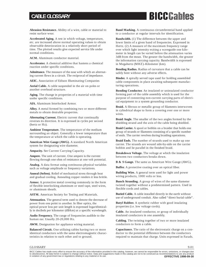
Abrasion Resistance. Ability of a wire, cable or material toresist surface wear.
Accelerated Aging. A test in which voltage, temperature,etc. are increased above normal operating values to obtainobservable deterioration in a relatively short period oftime. The plotted results give expected service life undernormal conditions.
ACM. Aluminum conductor material.
Accelerator. A chemical additive that hastens a chemicalreaction under specific conditions.
Admittance. The measure of the ease with which an alternat-ing current flows in a circuit. The reciprocal of impedance.
AEIC. Association of Edison Illuminating Companies
Aerial Cable. A cable suspended in the air on poles oranother overhead structure.
Aging. The change in properties of a material with timeunder specific conditions.
AIA. Aluminum Interlocked Armor.
Alloy. A metal formed by combining two or more differentmetals to obtain desirable properties.
Alternating Current. Electric current that continuallyreverses its direction. It is expressed in cycles per second(hertz or Hz).
Ambient Temperature. The temperature of the mediumsurrounding an object. Generally a lower temperature thanthe temperature at which the cable is operating.
American Wire Gauge (AWG). A standard North Americansystem for designating wire diameter.
Ampacity. See Current Carrying Capacity.
Ampere. The unit of current. One ampere is the currentflowing through one ohm of resistance at one volt potential.
Analog. A data format using continuous physical variablessuch as voltage amplitude or frequency variations.
Anneal (Soften). Relief of mechanical stress through heatand gradual cooling. Annealing copper renders it less brittle.
Armor. A protective metal covering commonly in the formof flexible interlocking aluminum or steel tape, steel wires,or aluminum sheath.
ASTM. American Society for Testing and Materials.
Attenuation. The general term used to denote the decrease ofpower from one point to another. In fiber optics, the optical power loss per unit length is expressed logarithmical-ly in decibels per kilometer (dB/km) at a specific wavelength.
Audio Frequency. The range of frequencies audible to thehuman ear. Usually 20-20,000 Hz.
AWM. Designation for appliance wiring material.
Balanced Circuit. One utilizing cables having two or moreidentical conductors with the same electromagnetic charac-teristics in relation to each other and to ground.
Band Marking. A continuous circumferential band appliedto a conductor at regular intervals for identification.
Bandwidth. (1) The difference between the upper andlower limits of a given band of frequencies. Expressed inHertz. (2) A measure of the maximum frequency rangeover which light intensity exiting a waveguide one kilo-meter in length can be varied before the attenuation varies3dB from the mean. The greater the bandwidth, the greaterthe information carrying capacity. Bandwidth is expressedin Megahertz (MHZ)–Kilometer (km).
Bending Radius. Radius of curvature that a cable can besafely bent without any adverse effects.
Binder. A spirally served tape used for holding assembledcable components in place awaiting subsequent manufac-turing operations.
Bonding Conductor. An insulated or uninsulated conductorforming part of the cable assembly which is used for thepurpose of connecting non-current carrying parts of electri-cal equipment to a system grounding conductor.
Braid. A fibrous or metallic group of filaments interwovenin cylindrical shape to form a covering over one or morewires.
Braid Angle. The smaller of the two angles formed by theshielding strand and the axis of the cable being shielded.
Braid Carrier. A spool or bobbin on a braider that holds onegroup of strands or filaments consisting of a specific numberof ends. The carrier revolves during braiding operations.
Braid Ends. The number of strands used to make up onecarrier. The strands are wound side-by-side on the carrierbobbin and lie parallel in the finished braid.
Breakdown Voltage. The voltage at which the insulationbetween two conductors breaks down.
B & S Gauge. The same as American Wire Gauge (AWG).
Buffer. A protective coating over an optical fiber.
Building Wire. A general term used for light and powerwiring products, 1000 volts or less.
Bunch Stranding. A group of wires of the same diametertwisted together without a predetermined pattern. Used inflexible cords and cables.
Buried Cable. A cable installed directly in the earth withoutuse of underground conduit. Also called “direct burial cable”.
Butyl Rubber. A synthetic rubber with good insulatingproperties (i.e. low voltage cords).
Cable. An insulated conductor, or group of individuallyinsulated conductors in one assembly.
Cabling. The twisting together of two or more insulatedconductors to form a cable.
Capacitance. The ratio of the electrostatic charge on a con-ductor to the potential difference between the conductorsrequired to maintain that charge. Units expressed in Farads.
CABLE GLOSSARY
9.02 GLOSSARYBICC Cables has made every effort to ensure the accuracy of the information provided in this catalog, however, we cannot be responsible for errors, omissions, or changes dueto obsolescence. All data herein is subject to change without notice. Data and suggestions made in this catalog are not to be construed as recommendations to use any productin violation of any government law or regulations relating to any material or its use. EFFECTIVE 1998-09-30
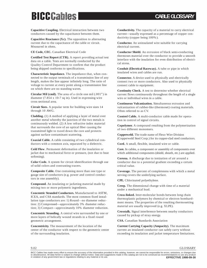
Capacitive Coupling. Electrical interaction between twoconductors caused by the capacitance between them.
Capacitive Reactance (Xc). The opposition to alternatingcurrent due to the capacitance of the cable or circuit.Measured in ohms.
CE Code, CEC. Canadian Electrical Code
Certified Test Report (CTR). A report providing actual testdata on a cable. Tests are normally conducted by theQuality Control Department to confirm that the productbeing shipped conforms to specifications.
Characteristic Impedance. The impedance that, when con-nected to the output terminals of a transmission line of anylength, makes the line appear infinitely long. The ratio ofvoltage to current at every point along a transmission lineon which there are no standing waves.
Circular Mil (cmil). The area of a circle one mil (.001”) indiameter (7.854 x 10⁻⁷ sq in). Used in expressing wirecross sectional area.
Circuit Sizes. A popular term for building wire sizes 14through 10 AWG.
Cladding. (1) A method of applying a layer of metal overanother metal whereby the junction of the two metals iscontinuously welded. (2) A low refractive index materialthat surrounds the core of an optical fiber causing thetransmitted light to travel down the core and protectsagainst surface contaminant scattering.
Coaxial Cable. A cable consisting of two cylindrical con-ductors with a common axis, separated by a dielectric.
Cold Flow. Permanent deformation of the insulation orjacket due to mechanical force or pressure, (not due to heatsoftening).
Color Code. A system for circuit identification through useof solid colors and contrasting tracers.
Composite Cable. One containing more than one type orgauge size of conductors (e.g. power and control conduc-tors in one assembly).
Compound. An insulating or jacketing material made bymixing two or more polymeric ingredients.
Concentric Stranded Conductors. Manufactured to ASTM,ICEA, and CSA standards. The most common fixed instal-lation type conductors are: 1) Round—no diameter reduc-tion: 2) Compressed—approximately 3% diameter reduc-tion; 3) Compact—approximately 10% diameter reduction.
Concentric Stranding. A central wire surrounded by one ormore layers of helically wound strands in a fixed roundgeometric arrangement.
Concentricity. The measurement of the location of the center of the conductor with respect to the geometric centerof the surrounding insulation.
Conductivity. The capacity of a material to carry electricalcurrent—usually expressed as a percentage of copper con-ductivity (copper being 100%).
Conductor. An uninsulated wire suitable for carrying electrical current.
Conductor Shield. An extrusion of black semi-conductingthermoses material over the conductor to provide a smoothinterface with the insulation for even distribution of electri-cal stress.
Conduit (Electrical Raceway). A tube or pipe in whichinsulated wires and cables are run.
Connector. A device used to physically and electrically connect two or more conductors. Also used to physicallyconnect cable to equipment.
Continuity Check. A test to determine whether electricalcurrent flows continuously throughout the length of a singlewire or individual wires in a cable.
Continuous Vulcanization. Simultaneous extrusion andvulcanization of rubber-like (thermoset) coating materials.Often referred to as CV.
Control Cable. A multi-conductor cable made for opera-tion in control of signal circuits.
Copolymer. A compound resulting from the polymerizationof two different monomers.
Copperweld. The trade name of Flexo Wire Division(Copperweld Steel Corp.) for its copper-clad steel conductors.
Cord. A small, flexible, insulated wire or cable.
Core. In cables, a component or assembly of components overwhich additional components (shield, sheath, etc.) are applied.
Corona. A discharge due to ionization of air around a conductor due to a potential gradient exceeding a certaincritical value.
Coverage. The percent of completeness with which a metalserving covers the underlying surface.
CPE. Chlorinated polyethylene.
Creep. The dimensional change with time of a materialunder a mechanical load.
Cross-linked. Inter-molecular bonds between long chainthermoplastic polymers by chemical or electron bombard-ment means. The properties of the resulting thermosettingmaterial are usually improved (e.g. XLPE).
Crosstalk. Signal interference between nearby conductorscaused by pickup of stray energy.
CSA. Canadian Standards Association
Current Carrying Capacity (Ampacity). The maximum current an insulated conductor can safely carry withoutexceeding its insulation and jacket temperature limitations.
CABLE GLOSSARY
GLOSSARY 9.03BICC Cables has made every effort to ensure the accuracy of the information provided in this catalog, however, we cannot be responsible for errors, omissions, or changes dueto obsolescence. All data herein is subject to change without notice. Data and suggestions made in this catalog are not to be construed as recommendations to use any productin violation of any government law or regulations relating to any material or its use. EFFECTIVE 1998-09-30
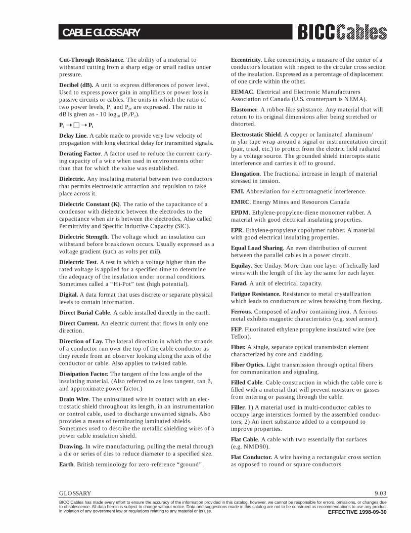
Cut-Through Resistance. The ability of a material to withstand cutting from a sharp edge or small radius underpressure.
Decibel (dB). A unit to express differences of power level.Used to express power gain in amplifiers or power loss inpassive circuits or cables. The units in which the ratio oftwo power levels, P1 and P2, are expressed. The ratio in dB is given as - 10 log10 (P1/P2).
P2 ➝ □ ➝ P1
Delay Line. A cable made to provide very low velocity ofpropagation with long electrical delay for transmitted signals.
Derating Factor. A factor used to reduce the current carry-ing capacity of a wire when used in environments otherthan that for which the value was established.
Dielectric. Any insulating material between two conductorsthat permits electrostatic attraction and repulsion to takeplace across it.
Dielectric Constant (K). The ratio of the capacitance of acondensor with dielectric between the electrodes to thecapacitance when air is between the electrodes. Also calledPermittivity and Specific Inductive Capacity (SIC).
Dielectric Strength. The voltage which an insulation canwithstand before breakdown occurs. Usually expressed as avoltage gradient (such as volts per mil).
Dielectric Test. A test in which a voltage higher than therated voltage is applied for a specified time to determinethe adequacy of the insulation under normal conditions.Sometimes called a “Hi-Pot” test (high potential).
Digital. A data format that uses discrete or separate physicallevels to contain information.
Direct Burial Cable. A cable installed directly in the earth.
Direct Current. An electric current that flows in only onedirection.
Direction of Lay. The lateral direction in which the strandsof a conductor run over the top of the cable conductor asthey recede from an observer looking along the axis of theconductor or cable. Also applies to twisted cable.
Dissipation Factor. The tangent of the loss angle of theinsulating material. (Also referred to as loss tangent, tan ,and approximate power factor.)
Drain Wire. The uninsulated wire in contact with an elec-trostatic shield throughout its length, in an instrumentationor control cable, used to discharge unwanted signals. Alsoprovides a means of terminating laminated shields.Sometimes used to describe the metallic shielding wires of apower cable insulation shield.
Drawing. In wire manufacturing, pulling the metal througha die or series of dies to reduce diameter to a specified size.
Earth. British terminology for zero-reference “ground”.
Eccentricity. Like concentricity, a measure of the center of aconductor’s location with respect to the circular cross sectionof the insulation. Expressed as a percentage of displacementof one circle within the other.
EEMAC. Electrical and Electronic ManufacturersAssociation of Canada (U.S. counterpart is NEMA).
Elastomer. A rubber-like substance. Any material that willreturn to its original dimensions after being stretched ordistorted.
Electrostatic Shield. A copper or laminated aluminum/m ylar tape wrap around a signal or instrumentation circuit(pair, triad, etc.) to protect from the electric field radiatedby a voltage source. The grounded shield intercepts staticinterference and carries it off to ground.
Elongation. The fractional increase in length of materialstressed in tension.
EMI. Abbreviation for electromagnetic interference.
EMRC. Energy Mines and Resources Canada
EPDM. Ethylene-propylene-diene monomer rubber. Amaterial with good electrical insulating properties.
EPR. Ethylene-propylene copolymer rubber. A materialwith good electrical insulating properties.
Equal Load Sharing. An even distribution of currentbetween the parallel cables in a power circuit.
Equilay. See Unilay. More than one layer of helically laidwires with the length of the lay the same for each layer.
Farad. A unit of electrical capacity.
Fatigue Resistance. Resistance to metal crystallizationwhich leads to conductors or wires breaking from flexing.
Ferrous. Composed of and/or containing iron. A ferrousmetal exhibits magnetic characteristics (e.g. steel armor).
FEP. Fluorinated ethylene propylene insulated wire (seeTeflon).
Fiber. A single, separate optical transmission elementcharacterized by core and cladding.
Fiber Optics. Light transmission through optical fibers for communication and signaling.
Filled Cable. Cable construction in which the cable core isfilled with a material that will prevent moisture or gassesfrom entering or passing through the cable.
Filler. 1) A material used in multi-conductor cables tooccupy large interstices formed by the assembled conduc-tors; 2) An inert substance added to a compound toimprove properties.
Flat Cable. A cable with two essentially flat surfaces(e.g. NMD90).
Flat Conductor. A wire having a rectangular cross sectionas opposed to round or square conductors.

CABLE GLOSSARY
9.04 GLOSSARYBICC Cables has made every effort to ensure the accuracy of the information provided in this catalog, however, we cannot be responsible for errors, omissions, or changes dueto obsolescence. All data herein is subject to change without notice. Data and suggestions made in this catalog are not to be construed as recommendations to use any productin violation of any government law or regulations relating to any material or its use. EFFECTIVE 1998-09-30
Flame Resistance. The ability of a material not to propa-gate flame once the heat source is removed (see FT1).
Flammability. The measure of the material’s ability to support combustion.
Flex Life. The measurement of the ability of a conductor orcable to withstand repeated bending before breaking.
Flexibility. The ease with which a cable may be bent with-out sustaining damage.
FT1. One of several CSA flame test designations for wiresand cables which pass the C22.2 No. 0.3 test requirements.(Other designations include FT2, FT4, etc.).
Fusion Splice. A splice accomplished by the application oflocalized heat sufficient to fuse or melt the ends of twolengths of optical fiber, forming a continuous single fiber.
Gauge. A term used to denote the physical size of a wire.
GND. Abbreviation for ground.
Graded-Index. A type of optical fiber in which the refrac-tive index of the core is in the form of a parabolic curve,decreasing toward the cladding. This type of fiber provideshigh bandwidth capabilities.
Ground (GND). 1) A conducting connection between anelectrical circuit and the earth, or other large conductingbody, to serve as an earth thus making a complete electricalcircuit; 2) Term used for non-current carrying conductor ina cable (see Bonding Conductor).
Halogen. A term used to identify any of the four elementschlorine, fluorine, bromine and iodine, grouped togetherbecause their chemical properties are similar.
Hard Drawn Copper Wire. Copper wire that has not beenannealed after drawing.
Heat Shock. A test to determine stability of a material bysudden exposure to a high temperature for a short periodof time.
Henry. The unit of inductance.
Hertz (Hz). A term replacing cycles-per-second as an indi-cation of frequency.
Hi-Pot (High Potential). A test designated to determine thehighest voltage that can be applied to a conductor withoutbreaking down the insulation (see Dielectric Test).
High Voltage (HV). Generally, a wire or cable with anoperating voltage of over 600 volts.
Hook-Up Wire. A wire used for low current, low voltage(under 1000 volts) applications within enclosed electronicequipment.
Hygroscopic. A material capable of absorbing moisturefrom the air.
Hypalon®. Dupont’s trade name for their chlorosulfonatedpolyethylene, an ozone resistant synthetic rubber.
ICEA (formerly IPCEA). Insulated Cable EngineersAssociation.
IEEE. Institute of Electrical and Electronics Engineers.
Impact Strength. A test for determining the mechanicalpunishment a cable can withstand without physical or elec-trical breakdown by impacting with a given weight,dropped a given distance, in a controlled environment.
Impedance. The total opposition that a circuit offers to theflow of alternating current or any other varying current ata particular frequency. It is a combination of resistance Rand reactance X, measured in ohms.
Inductance. The property of a circuit or circuit element thatopposes a change in current flow, thus causing current changesto lag behind voltage changes. It is measured in henrys.
Insulation. A material having good dielectric propertiespermitting close assembly of conductors in cable andequipment.
Insulation Level. A designation used to identify the insula-tion thickness required to protect a high voltage cableunder ground fault conditions. Expressed as a percentage(e.g. 100% level, 133% level).
Insulation Shield (HV Cable). A two part shield consistingof a non-metallic component and a metallic component.The first component is an extrusion of black semi-conduct-ing thermoset material over the insulation which providesuniform radial stress distribution across the insulation. Thesecond component is a metallic shield which is typicallycopper tape or wire that functions as a bonding (ground-ing) conductor and/or a neutral conductor. The metallicshield also serves to conduct ground fault current in theevent of insulation failure. See also drain wire.
Insulation Stress. High voltage stress which causes molecu-lar separation in the insulation at sharp projections in theconductor. Controlled by conductor and insulation shield-ing, called a stress relief shield. Measured in volts per mil.
Interaxial Spacing. Center to center conductor spacing.
Interstices. Voids or valleys between individual strands in aconductor or between insulated conductors in a multi-con-ductor cable, (intersticial spaces).
Irradiation. In insulations, the exposure of the material tohigh energy emissions for the purpose of favorably alteringthe molecular structure by crosslinking.
Jacket. An outer covering, usually non-metallic, mainlyused for protection against the environment.
kcmil. One thousand circular mils (MCM).
KILO. A prefix denoting 1000 (103).
kV. Kilovolt (1000 volts).
Laminated Tape. A tape consisting of two or more layersof different materials bonded together (e.g. aluminum/Mylar®).

CABLE GLOSSARY
GLOSSARY 9.05BICC Cables has made every effort to ensure the accuracy of the information provided in this catalog, however, we cannot be responsible for errors, omissions, or changes dueto obsolescence. All data herein is subject to change without notice. Data and suggestions made in this catalog are not to be construed as recommendations to use any productin violation of any government law or regulations relating to any material or its use. EFFECTIVE 1998-09-30
Lay. The length measured along the axis of a wire or cablerequired for a single strand (in stranded wire) or conductor(in cable) to make one complete turn about the axis of theconductor or cable.
Lay Direction. The twist in the cable as indicated by the topstrands while looking along the axis of the cable away fromthe observer. Described as “right hand” or “left hand”.
Leakage Current. The undesirable flow of current throughor over the surface of an insulation.
Line Drop (Voltage Drop). A voltage loss occurringbetween any two points in a power circuit. Such loss, ordrop, is due to the resistance, reactance, or leakage of thecircuit, type of cable and configuration.
Line Voltage. The value of the potential existing on a supplyor power line. Rated voltage of cables.
LOCA. Abbreviation for loss of coolant accident, a systemmalfunction associated with nuclear generating stations.
Longitudinal Shield. A tape shield, flat or corrugated, appliedlongitudinally with the axis of the core being shielded.
Loss Factor. The product of the dissipation and dielectricconstant of an insulating material.
µA. Microampere. One-millionth of an ampere (10-6),
mA. Milliampere. One-thousandth of an ampere (10-3).
Magnetic Noise. Caused by current frequency. An ACpowerline creates a magnetic field around that cable, thismagnetic field causes the magnetic noise in neighboringcontrol or instrumentation circuits.
MCM. One thousand circular mils (kcmil).
Meg or Mega. A prefix denoting 1,000,000 (106).
Megarad. A unit for measuring radiation dosage.
Messenger. The linear supporting member, usually a highstrength steel wire, used as the supporting element of a suspended aerial cable. The messenger may be an integralpart of the cable, or exterior to it.
Mho. The unit of conductivity. The reciprocal of an ohm.
Micro. A prefix denoting one-millionth (106).
Micron. (µ) Millionth of a meter = 10-6 meter.
Mil. A unit of length equal to one-thousandth of an inch(.001”). Common unit for insulation thickness.
Milli. A prefix denoting one-thousandth (10-3).
Modulus of Elasticity. The ratio of stress to strain in anelastic material.
Moisture Absorption. The amount of moisture, in percent-age, that a material will absorb under specified conditions.
Moisture Resistance. The ability of a material to resistabsorbing moisture from the air or when immersed in water.
Multi-Conductor Cable. A cable consisting of two or moreconductors, either cabled or laid in a flat parallel construc-tion, with or without a common overall covering.
Mutual Capacitance. Capacitance between two conductorswhen all other conductors including ground are connectedtogether.
Mylar®. DuPont trade name for a polyester material.
Nano. A numerical prefix denoting one-billionth (10 -9).
National Electrical Code (NEC). A U.S. consensus standardpublished by the National Fire Protection Association(NFPA) and incorporated in OSHA regulations. (CanadianCounterpart is the CE Code).
NEMA. National Electrical Manufacturers Association.(Canadian counterpart is EEMAC).
Neoprene. A synthetic rubber with good resistance to oil,chemicals, and flame. Also called polychloroprene.
Nomex®. Dupont trademark for a temperature resistant,flame-retardant nylon.
Non Hygroscopic. A material incapable of taking up orabsorbing moisture from the air.
Nylon®. An abrasion-resistant thermoplastic with goodchemical resistance. A DuPont registered trademark.
OHM. The electrical unit of resistance.
OSHA. Abbreviation for the U.S. Occupational Safety andHealth Act.
Overlap. The amount the trailing edge laps over the leadingedge of a spiral tape wrap.
Oxygen Index. Percentage of oxygen necessary to supportcombustion in a gas mixture. Flame retardant materialshave a higher oxygen index.
Pair. Two insulated wires of a single circuit twisted togeth-er or laid parallel.
Parallel Cable. Two or more cables used to share the cur-rent in heavily loaded power circuits which permits the useof smaller conductors.
Percentage Conductivity. Conductivity of a materialexpressed as a percentage of that of copper. Also used toindicate ratio of conductance between the phase conductorand the neutral in power cables.
Pick. Distance between two adjacent crossover points ofbraid filaments. The measurement in picks per inch indicatesthe degree of coverage.
PICO. A prefix denoting one-millionth of one-millionth(10-12).
Pitch. In flat cable, the nominal distance between the indexedges of two adjacent conductors.
Pitch Diameter. Diameter of a circle passing through the centerof the conductors in any layer of a multi-conductor cable.

CABLE GLOSSARY
9.06 GLOSSARYBICC Cables has made every effort to ensure the accuracy of the information provided in this catalog, however, we cannot be responsible for errors, omissions, or changes dueto obsolescence. All data herein is subject to change without notice. Data and suggestions made in this catalog are not to be construed as recommendations to use any productin violation of any government law or regulations relating to any material or its use. EFFECTIVE 1998-09-30
Plastic Deformation. Change in dimensions under load thatis not recovered when the load is removed.
Plasticizer. A chemical agent added to plastics to makethem softer and more pliable.
Plenum Cable. Cable approved for installation in plenums,(e.g. suspended ceiling) without the need for conduit.
Polyester. Polyethylene terephthalate which is used exten-sively in the production of a high strength moisture resis-tant film used as a cable core wrap (see Mylar).
Polyethylene (PE). A thermoplastic material having excel-lent electrical and physical properties.
Polymer. A material of high molecular weight formed bythe chemical union of monomers.
Polyolefin. A family of thermoplastics based upon theunsaturated hydrocarbons know as olefins. When combinedwith butylene or styrene polymers they form compoundssuch as polyethylene and polypropylene.
Polypropylene (PPE). A thermoplastic similar to polyethylenebut stiffer and having a higher softening point (temperature).
Polyvinyl Chloride (PVC). A general purpose thermoplasticused for low voltage wire and cable insulation, and for jackets.
Power Factor. The ratio of resistance to impedance. Theratio of the actual power of an alternating current toapparent power. Mathematically, the cosine of the anglebetween the voltage applied and the current resulting.
Primary Insulation. The first layer of non-conductive mate-rial applied over a conductor, whose prime function is toact as electrical insulation.
Pulling Eye. A device fastened to a cable to which a hookmay be attached in order to pull the cable.
Quad. Four insulated wires of a single circuit.
REA. Rural Electrification Administration. A branch of theU.S. Department of Agriculture.
Reactance. The opposition offered to the flow of alternat-ing current by inductance or capacitance of a componentor circuit.
Reel Drum Diameter. Diameter of the drum (or hub) of the reel.
Reel Flange Diameter (Reel Height). Diameter of the reelflanges
Reel Traverse. Width of space between reel flanges.
Reel Width. Overall width of reel.
Ridge Marker. One or more ridges running laterally alongthe outer surface of a insulated wire or cable for purposesof identification.
Root Mean Square (RMS). The effective value of an alter-nating current or voltage.
Rope Lay Conductor. A conductor composed of a centralcore surrounded by one or more layers of helically laidgroups of wires used in portable cables.
Rubber. A general term used to describe wire insulationand jackets made of thermosetting elastomers, such as natural or synthetic rubbers, EPR, neoprene, Hypalon,butyl rubber, and others.
SBR. A copolymer of styrene and butadiene. Also GR-S orBuna-S. Most commonly used type of synthetic rubber.
Self Extinguishing. The characteristic of a material whoseflame is extinguished after the igniting flame is removed.
Semi-Conductor. In wire industry terminology, a materialpossessing electrical conductivity that falls somewherebetween that of conductors and insulators. Usually made byadding carbon particles to an insulator (e.g. conductor shieldand insulation shield). Not the same as semi-conductormaterials such as silicon, germanium, etc. used for makingtransistors and diodes.
Separator. Pertaining to wire and cable, a layer of insulatingmaterial such as textile paper, Mylar, etc. which is placedbetween a conductor and its dielectric, between a cable jacketand the components it covers, or between various compo-nents of a multi-conductor cable. It can be utilized to improvestripping qualities, flexibility, or can offer additional mechani-cal or electrical protection to the components it separates.
Served Wire Armor (SWA). Spiral wrap of galvanized steelwires applied around a cable to afford mechanical protec-tion and increase the cable pulling tension characteristics,(mineshaft, submarine cable, etc.). Also used to denote steelwire armor.
Sheath. The outer covering or jacket of a multi-conductorcable. Usually non-metallic.
Shield (Electrostatic). In cables, a metallic layer placedaround a conductor or group of conductors to prevent electrostatic interference between the enclosed wires andexternal fields. Also see Insulation Shield.
Shrink Tubing. Tubing which has been extruded,crosslinked, and mechanically expanded which whenreheated will return to its original diameter.
SIA. Steel Interlocked Armor.
Side Wall Bearing Pressure (SWBP). A term used in refer-ence to the pressure on a cable which is being pulled arounda curved surface under tension. If excessive, SWBP candamage cable components and reduce the life of the cable.
Signal Cable. A cable designed to carry current of usuallyless than one ampere per conductor to operate signal cir-cuit devices.
Silicone. A material made from silicone and oxygen.Can bein thermosetting elastomer or liquid form. The thermoset-ting elastomer form is noted for high heat resistance.

CABLE GLOSSARY
GLOSSARY 9.07BICC Cables has made every effort to ensure the accuracy of the information provided in this catalog, however, we cannot be responsible for errors, omissions, or changes dueto obsolescence. All data herein is subject to change without notice. Data and suggestions made in this catalog are not to be construed as recommendations to use any productin violation of any government law or regulations relating to any material or its use. EFFECTIVE 1998-09-30
Skin Effect. The tendency of alternating current to concen-trate and to travel only on the surface of a conductor.Tendency increases with increase in frequency.
Sleeving. An extruded tube.
Spark Test. A test designed to locate imperfections (usuallypin-holes) in the insulation of a wire or cable by applicationof voltage for a very short period of time while the wire isbeing drawn through the electrode field.
Specific Gravity. The ratio of the density (mass per unitvolume) of a material to that of water.
Specific Inductive Capacity (SIC). Same as dielectric con-stant (See Dielectric Constant).
Tank Test. A voltage insulation test in which the insulatedwire or cable is submerged in water and voltage is appliedbetween the conductor and water serving as ground.Shielded cables are generally not tank tested due to the pos-sibility of introducing contaminants on the outer surface ofthe insulation.
Teflon®. DuPont Company trademark for fluorocarbonresins. (See FEP and TFE).
Temperature Rating. The maximum temperature at whichan insulating material may be used in continuous operationwithout loss of its basic properties (i.e. operating, overload,short circuit). The minimum temperature for safe handling.
Tensile Strength. The pull stress required to break a givenspecimen. Measured in pounds per square inch. Alsoreferred to as “Ultimate Tensile Strength”.
TFE. Tetrafluoroethylene. A thermoplastic material withgood electrical insulating properties and chemical and heatresistance.
Thermoplastic. A material that can be softened repeatedlyby heating and hardened by cooling through a temperaturerange characteristic of the plastic, and that in the softenedstate can be shaped by molding or extrusion.
Thermoset. A material that has been vulcanized by heat orother means and is substantially infusible and insoluble.
Three Conductor Cable. Three insulated conductors assem-bled with other necessary cable components (shield, filler,etc.) to form a core, protected by an overall jacket.
Tinned Copper. Tin coating added to copper to aid in sol-dering and inhibit corrosion.
Tray. A cable tray system is a unit or assembly of units orsections, and associated fittings, made of non-combustiblematerials forming a rigid structural system used to supportcables. Cable tray systems (previously termed continuousrigid cable supports) include ladders, troughs, channels,solid bottom trays, and similar structures.
Tray Cable. A factory assembled multi-conductor or multi-pair control, signal or power cable specifically approvedunder the Canadian Electrical Code for installation in trays.
Triad. Three insulated wires of a single circuit forming a unit.(Two or more units are cabled to form a multi-triad cable.)
Triplexed Cable. Three individual cables twisted together.
UL. Underwriters Laboratories. A non-profit independentorganization, which operates a listing service for electricaland electronic materials and equipment. (Canadian counter-part is CSA).
UHF. Abbreviation for ultra high frequency, 300 to 3,000 MHZ.
Unilay. A conductor with more than one layer of helicallylaid wires with the direction of lay and length of lay thesame for all layers.
Velocity of Propagation. The speed of an electrical signaldown a length of cable compared to speed in free spaceexpressed as a percent. It is the reciprocal of the squareroot of the dielectric constant of the cable insulation.
VHF. Abbreviation for very high frequency, 30 to 300 MHZ.
Voltage. The term most often used in place of electromotiveforce, potential, potential difference or voltage drop to des-ignate the electric pressure that exists between two pointsand is capable of producing a current when a closed circuitis connected between two points.
Voltage Rating. 1) The highest voltage that can be continu-ously applied to a wire in conformance with the standardor specification; 2) The “system” voltage printed on thewire or cable.
Volume Resistivity. The electrical resistance between opposite faces of a one cm. cube of insulating material,commonly expressed in ohms-centimeter.
Vulcanization. An irreversible process during which a com-pound, through a change in its chemical structure (e.g. cross-linking), becomes less plastic and more resistant to swellingby organic liquids and elastic properties are conferred,improved or extended over a greater range of temperatures.
VW-1. A flammability rating established by UnderwritersLaboratories for wires and cables that pass a speciallydesigned vertical flame test, formerly designated FR-1.Similar to CSA designation FT1.
Watt. A unit of electric power.
Wicking. The longitudinal flow of a liquid in a wire orcable due to capillary action.
Wire. A conductor; bare or insulated.
Yield Strength. The minimum stress at which a material willstart to physically deform without further increase in load.

REFERENCE STANDARDS
9.08 REFERENCE STANDARDSBICC Cables has made every effort to ensure the accuracy of the information provided in this catalog, however, we cannot be responsible for errors, omissions, or changes dueto obsolescence. All data herein is subject to change without notice. Data and suggestions made in this catalog are not to be construed as recommendations to use any productin violation of any government law or regulations relating to any material or its use. EFFECTIVE 1998-09-30
AAR S-501: Specification for Wire & Cables
AAR 581.3: Specification for Single Conductor, CleanStripping Rubber Insulated, 0–600 Volts, Neoprene JacketedCable for Locomotive and Car Equipment
AAR 589: Specification for Single Conductor Chloro-sulfonated Polyethylene Integral Insulated-Jacketed, 0-300V,0-600V Cable for Locomotive and Car Equipment
AEIC CS 1: Specifications for Solid-Type Impregnated-Paper-Insulated Metallic Sheathed Cable
AEIC CS2: Specifications for Impregnated-Paper andLaminated Paper-Polypropylene Insulated Cable, High-Pressure Pipe-Type
AEIC CS3: Specifications for Impregnated-Paper-Insulated,Metallic Sheathed Cable, Low Pressure Gas-Filled Type
AEIC CS4: Specifications for Impregnated-Paper-InsulatedLow and Medium Pressure Self Contained Liquid Filled Cable
AEIC CS5: Specifications for Thermoplastic and CrosslinkedPolyethylene Insulated Shielded Power Cables Rated 5Through 69 kV
AEIC CS6: Specifications for Ethylene Propylene RubberInsulated Shielded Power Cables Rated 5 Through 69 kV
AEIC CS7: Specifications for Crosslinked PolyethyleneInsulated Shielded Power Cables Rated 46 Through 138 kV
ANSI C2: National Electrical Safety Code
ANSI MC96.1: Thermocouple Extension Wire Calibration
ANSI N45.2: Packaging, Shipping, Receiving, Storage andHandling of Items for Nuclear Power Plants
ASTM B 1: Standard Specification for Hard-Drawn Copper Wire
ASTM B 2: Standard Specification for Medium-Hard-DrawnCopper Wire
ASTM B 3: Standard Specification for Soft or AnnealedCopper Wire
ASTM B 8: Standard Specification for Concentric-LayStranded Copper Conductors, Hard, Medium-Hard, or Soft
ASTM B 33: Standard Specification for Tinned Soft orAnnealed Copper Wire for Electrical Purposes
ASTM B 105: Standard Specification for Hard-DrawnCopper Alloy Wires for Electrical Conductors
ASTM B 170: Standard Specification for Oxygen-FreeElectrolytic Copper
ASTM B 172: Standard Specification for Rope-Lay-StrandedCopper Conductors Having Bunch-Stranded Members, forElectrical Conductors
ASTM B 173: Standard Specification for Rope-Lay-StrandedCopper Conductors Having Concentric-Stranded Members,for Electrical Conductors
ASTM B 174: Standard Specification for Bunch-StrandedCopper Conductors for Electrical Conductors
ASTM B 189: Standard Specification for Lead-Coated andLead-Alloy-Coated Soft Copper Wire for Electrical Purposes
ASTM B 193: Standard Test Method for Resistivity ofElectrical Conductor Materials
ASTM B 226: Standard Specification for Cored, Annular,Concentric-Lay-Stranded Copper Conductors
ASTM B 227: Standard Specification for Hard-DrawnCopper-Clad Steel Wire
ASTM B 228: Standard Specification for Concentric-Lay-Stranded Copper-Clad Steel Conductors
ASTM B 229: Standard Specification for Concentric-Lay-Stranded Copper and Copper-Clad Steel CompositeConductors
ASTM B 230: Standard Specification for Aluminum 1350-H19 Wire for Electrical Purposes
ASTM B 230M: Standard Specification for Aluminum 1350-H19 Wire for Electrical Purposes [Metric]
ASTM B 231: Standard Specification for Concentric-Lay-Stranded Aluminum 1350 Conductors
ASTM B 231 M: Standard Specification for Concentric-Lay-Stranded Aluminum 1350 Conductors [Metric]
ASTM B 232: Standard Specification for Concentric-Lay-Stranded Aluminum Conductors, Coated Steel-Reinforced(ACACARSR)
ASTM B 232M: Standard Specification for Concentric-Lay-Stranded Aluminum Conductors, Coated Steel-Reinforced(ACSR) [Metric]
ASTM B 233: Standard Specification for Aluminum 1350Drawing Stock for Electrical Purposes
ASTM B 246: Standard Specification for Tinned Hard-Drawn and Medium-Hard-Drawn Copper Wire forElectrical Purposes
ASTM B 258: Standard Specification for Standard NominalDiameters and Cross-Sectional Areas of AWG Sizes of SolidRound Wires Used as Electrical Conductors
ASTM B 263: Standard Test Method for Determination ofCross-Sectional Area of Stranded Conductors
ASTM B 286: Standard Specification for Copper Conductorsfor Use in Hookup Wire for Electronic Equipment
ASTM B 298: Standard Specification for Silver-Coated Softor Annealed Copper Wire
ASTM B 324: Standard Specification for Nickel-Coated Softor Annealed Copper Wire
ASTM B 341: Standard Specification for Aluminum-Coated(Aluminized) Steel Core Wire for Aluminum Conductors,Steel-Reinforced (ACSR/AZ)
ASTM B 341M: Standard Specification for Aluminum-Coated (Aluminized) Steel Core Wire for AluminumConductors, Steel-Reinforced (ACSR/AZ) [Metric]

REFERENCE STANDARDS
REFERENCE STANDARDS 9.09BICC Cables has made every effort to ensure the accuracy of the information provided in this catalog, however, we cannot be responsible for errors, omissions, or changes dueto obsolescence. All data herein is subject to change without notice. Data and suggestions made in this catalog are not to be construed as recommendations to use any productin violation of any government law or regulations relating to any material or its use. EFFECTIVE 1998-09-30
ASTM B 355: Standard Specification for Nickel-Coated Soft or Annealed Copper Wire
ASTM B 397: Standard Specification for Concentric-Lay-Stranded Aluminum-Alloy 5005-H19 Conductors
ASTM B 398: Standard Specification for Aluminum-Alloy6201-T81 Wire for Electrical Purposes
ASTM B 398M: Standard Specification for Aluminum-Alloy6201-T81 Wire for Electrical Purposes [Metric]
ASTM B 399: Standard Specification for Concentric-Lay-Stranded Aluminum-Alloy 6201-T81 Conductors
ASTM B 399M: Standard Specification for Concentric-Lay-Stranded Aluminum-Alloy 6201-T81 Conductors [Metric]
ASTM B 400: Standard Specification for Compact RoundConcentric-Lay-Stranded Aluminum 1350 Conductors
ASTM B 401: Standard Specification for Compact RoundConcentric-Lay-Stranded Aluminum Conductors, Steel-Reinforced (ACSR/COMP)
ASTM B 416: Standard Specification for Concentric-Lay-Stranded Aluminum-Clad Steel Conductors
ASTM B 452: Standard Specification for Copper-Clad SteelWire for Electronic Application
ASTM B 470: Standard Specification for Bonded CopperConductors for Use in Hookup Wires for ElectronicEquipment
ASTM B 496: Standard Specification for Compact RoundConcentric-Lay-Stranded Copper Conductors
ASTM B 498: Standard Specification for Zinc-Coated(Galvanized) Steel Core Wire for Aluminum Conductors,Steel-Reinforced (ACSR)
ASTM B 498M: Standard Specification for Zinc-Coated(Galvanized) Steel Core Wire for Aluminum Conductors,Steel-Reinforced (ACSR) [Metric]
ASTM B 500: Standard Specification for Zinc-Coated(Galvanized), Zinc-5% Aluminum Mischmetal Alloy-Coated, and Aluminum-Coated (Aluminized) Stranded SteelCore for Aluminum Conductors, Steel-Reinforced (ACSR)
ASTM B 501: Standard Specification for Silver-Coated,Copper-Clad Steel Wire for Electronic Application
ASTM B 502: Standard Specification for Aluminum-CladSteel Core Wire for Aluminum Conductors, Aluminum-CladSteel Reinforced
ASTM B 520: Standard Specification for Tin-Coated,Copper-Clad Steel Wire for Electronic Application
ASTM B 524: Standard Specification for Concentric-Lay-Stranded Aluminum Conductors, Aluminum-AlloyReinforced (ACAR, 1350/6201)
ASTM B 524M: Standard Specification for Concentric-Lay-Stranded Aluminum Conductors, Aluminum-AlloyReinforced (ACAR, 1350/6201) [Metric]
ASTM B 549: Standard Specification for Concentric-Lay-Stranded Aluminum Conductors, Aluminum-Clad SteelReinforced (ACSR/AW)
ASTM B 559: Standard Specification for Nickel-Coated,Copper-Clad Steel Wire for Electronic Application
ASTM B 606: Standard Specification for High-StrengthZinc-Coated (Galvanized) Steel Core Wire for Aluminumand Aluminum Alloy Conductors, Steel Reinforced
ASTM B 609: Standard Specification for Aluminum 1350Round Wire, Annealed and Intermediate Tempers, forElectrical Purposes
ASTM B 609M: Standard Specification for Aluminum 1350Round Wire, Annealed and Intermediate Tempers, forElectrical Purposes [Metric]
ASTM B 624: Standard Specification for High-Strength,High-Conductivity Copper-Alloy Wire for ElectronicApplication
ASTM B 682: Standard Specification for Standard MetricSizes of Electrical Conductors
ASTM B 701: Standard Specification for Concentric-Lay-Stranded Self-Damping Aluminum Conductors, Steel-Reinforced (ACSR/SD)
ASTM B 711: Standard Specification for Concentric-Lay-Stranded Aluminum-Alloy Conductors, Steel Reinforced(AACSR) (6201)
ASTM B 738: Standard Specification for Fine-Wire Bunch-Stranded and Rope-Lay Bunch Stranded Copper Conductorsfor Use as Electrical Conductors
ASTM B 778: Standard Specification for Shaped WireCompact Concentric-Lay-Stranded Aluminum Conductors(AAC/TW)
ASTM B 779: Standard Specification for Shaped WireCompact Concentric-Lay-Stranded Aluminum Conductors,Steel Reinforced (ACSR/TW)
ASTM B 784: Standard Specification for ModifiedConcentric-Lay-Stranded Copper Conductors for Use inInsulated Electrical Cables
ASTM B 785: Standard Specification for Compact RoundModified Concentric-Lay-Stranded Copper Conductors forUse in Insulated Electrical Cables
ASTM B 786: Standard Specification for 19 WireCombination Unilay-Stranded Aluminum 1350 Conductorsfor Subsequent Insulation
ASTM B 787: Standard Specification for 19 WireCombination Unilay-Stranded Copper Conductors forSubsequent Insulation
ASTM B 801: Standard Specification for Concentric-Lay-Stranded Conductors of 8000 Series Aluminum Alloy forSubsequent Covering or Insulation

REFERENCE STANDARDS
9.10 REFERENCE STANDARDSBICC Cables has made every effort to ensure the accuracy of the information provided in this catalog, however, we cannot be responsible for errors, omissions, or changes dueto obsolescence. All data herein is subject to change without notice. Data and suggestions made in this catalog are not to be construed as recommendations to use any productin violation of any government law or regulations relating to any material or its use. EFFECTIVE 1998-09-30
ASTM B 802: Standard Specification for Zinc-5%Aluminum-Mischmetal Alloy-Coated Steel Core Wire forAluminum Conductors, Steel Reinforced (ACSR)
ASTM B 803: Standard Specification for High-StrengthZinc-5 % Aluminum-Mischmetal Alloy Coated Steel CoreWire for Aluminum and Aluminum-Alloy Conductors, SteelReinforced
ASTM D 149: Standard Test Method for Dielectric Break-down Voltage and Dielectric Strength of Solid ElectricalInsulating Materials at Commercial Power Frequencies
ASTM D 470: Method of Testing Crosslinked Insulationsand Jackets for Wire and Cable
ASTM D 866: Specification for Styrene-Butadiene (SBR)Synthetic Rubber Jacket for Wire and Cable
ASTM D 1047: Specification for Polyvinyl Chloride (PVC)Jacket for Wire and Cable
ASTM D 1351: Specification for Polyethylene Insulation forWire and Cable
ASTM D 1352: Specification for Ozone-Resisting ButylRubber Insulation for Wire and Cable
ASTM D 1523: Method for Synthetic Rubber Insulation forWire and Cable, 90° Operation
ASTM D 1679: Specification for Synthetic Rubber Heatand Moisture-Resisting Insulation for Wire and Cable, 75°C Operation
ASTM D 2219: Specification for Polyvinyl Chloride (PVC)Insulation for Wire and Cable, 60° Operation
ASTM D 2220: Specification for Polyvinyl Chloride (PVC)Insulation for Wire and Cable, 75° Operation
ASTM D 2308: Specification for Polyethylene Jacket forElectrical Insulated Wire and Cable
ASTM D 2526: Specification for Ozone-Resisting SiliconeRubber Insulation for Wire and Cable
ASTM D 2655: Specification for Crosslinked PolyethyleneInsulation for Wire and Cable Rated 0 to 2000V
ASTM D 2656: Specification for Crosslinked PolyethyleneInsulation for Wire and Cable Rated 2001 to 35000V
ASTM D 2768: Specification for General-Purpose Ethylene-Propylene Rubber Jacket for Wire and Cable
ASTM D 2770: Specification for Ozone-Resisting Ethylene-Propylene Rubber Integral Insulation and Jacket for Wireand Cable
ASTM D 2802: Specification for Ozone-Resistant Ethylene-Propylene Rubber Insulation for Wire and Cable
ASTM D 3004: Specification for Extruded Thermosettingand Thermoplastic Semi-Conducting Conductor andInsulation Shields
ASTM D 3485: Specification for Smooth-Wall CoilablePolyethylene (PE) Conduit (Duct) for Preassembled Wireand Cable
ASTM D 3554: Specification for Track-Resistant BlackThermoplastic High Density Polyethylene Insulation forWire and Cable
ASTM D 3555: Specification for Track-Resistant BlackCrosslinked Thermosetting Polyethylene Insulation for Wireand Cable
ASTM D 4244: Specification for General-Purpose, Heavy-Duty and Extra-Heavy Duty Acrylonitrile-Butadiene/Polyvinyl Chloride (NBR/PVC) Jackets for Wire and Cable
ASTM D 4245: Specification for Ozone-ResistantThermoplastic Elastomer Insulation for Wire and Cable,90°C Dry - 75°C Wet Operation
ASTM D 4246: Specification for Ozone-ResistantThermoplastic Elastomer Insulation for Wire and Cable,90°C Operation
ASTM D 4247: Specification for General-Purpose BlackHeavy-Duty and Black Extra-Heavy Duty PolychloropreneJackets for Wire and Cable
ASTM D 4313: Specification for General Purpose Heavy-Duty and Extra-Heavy-Duty Crosslinked Chlorinated Poly-ethylene Jackets for Wire and Cable
ASTM D 4314: Specification for General Purpose Heavy-Duty and Extra-Heavy-Duty Crosslinked ChlorosulfonatedPolyethylene Jackets for Wire and Cable
ASTM D 4363: Specification for Thermoplastic ChlorinatedPolyethylene Jacket for Wire and Cable
ASTM D 4496: Test Method of DC Resistance or Conductance of Moderately Conductive Materials
ASTM D 4568: Test Methods for Evaluating CompatibilityBetween Cable Filling and Flooding Compounds andPolyolefin Cable Materials
ASTM D 4967: Guide for Selecting Materials to Be Used for Insulation, Jacketing, and Strength Componentsin Fiber Optic Cables
CAN3-Z299.0: Guide for Selecting and Implementing theCAN3-Z299 Quality Assurance Program Standards
CAN3-Z299.1: Standard for Quality Assurance Program -Category 1
CAN3-Z299.2: Standard for Quality Assurance Program -Category 2
CAN3-Z299.3: Standard for Quality Assurance Program -Category 3
CAN3-Z299.4: Standard for Quality Assurance Program -Category 4
CSA C22.1: Canadian Electrical Code, Part 1, SafetyStandard for Electrical Installations
REFERENCE STANDARDS
REFERENCE STANDARDS 9.11BICC Cables has made every effort to ensure the accuracy of the information provided in this catalog, however, we cannot be responsible for errors, omissions, or changes dueto obsolescence. All data herein is subject to change without notice. Data and suggestions made in this catalog are not to be construed as recommendations to use any productin violation of any government law or regulations relating to any material or its use. EFFECTIVE 1998-09-30
CSA C22.2 No. 0.3: Standard for Test Methods forElectrical Wires and Cables
CSA C22.2 No. 16: Standard for Insulated Conductors forPower-Operated Electronic Devices
CAN/CSA C22.2 No. 211: Standard for Cord Sets andPower-Supply Cords
CSA C22.2 No. 35: Standard for Extra-Low-VoltageControl Circuit Cables, Low-Energy Control Cable, andExtra-Low-Voltage Control Cable
CSA C22.2 No. 38: Standard for Thermoset Insulated Wiresand Cables
CAN/CSA C22.2 No. 48: Standard for NonmetallicSheathed Cable
CAN/CSA C22.2 No. 49: Standard for Flexible Cords and Cables
CAN/CSA C22.2 No. 51: Standard for Armoured Cable
CSA C22.2 No. 52: Standard for Service-Entrance Cables
CSA C22.2 No. 75: Standard for Thermoplastic-InsulatedWires and Cables
CAN/CSA C22.2 No. 96: Standard for Portable Power Cables
CSA C22.2 No. 116: Standard for Coil-Lead Wires
CSA C22.2 No. 123: Standard for Aluminum Sheathed Cables
CSA C22.2 No. 124: Standard for Mineral-Insulated Cable
CSA C22.2 No. 127: Standard for Equipment Wires
CSA C22.2 No. 129: Standard for Neutral Supported Cable
CSA C22.2 No. 130: Standard for Heating Cables andHeating Cable Sets
CAN/CSA C22.2 No. 130.1: Standard for Heat-TracingCable Systems for Use in Industrial Locations
CAN/CSA C22.2 No. 131: Standard for Type TECK 90 Cable
CSA C22.2 No. 138: Standard for Heat Tracing Cable and Cable Sets for Use in Hazardous Locations
CSA C22.2 No. 174: Standard for Cables and Cable Glandsfor Use in Hazardous Locations
CSA C22.2 No. 179: Standard for Airport Series LightingCables
CSA C22.2 No.188: Standard for Splicing Wire and Cable Connectors
CSA C22.2 No. 198.2: Standard for Underground CableSplicing Kits
CAN/CSA C22.2 No. 203: Standard for Modular WiringSystems for Office Furniture
CSA C22.2 No. 208: Standard for Fire Alarm and Signal Cable
CAN/CSA C22.2 No. 210.2: Standard for Appliance WiringMaterial Products
CAN/CSA C22.2 No. 214: Standard for CommunicationsCables
CSA C22.2 No. 222: Standard for Type FCC Under-CarpetWiring System
CSA C22.2 No. 230: Standard for Tray Cable
CSA C22.2 No. 232: Standard for Optical Fiber Cables
CAN/CSA C22.2 No. 233: Standard for Cords and CordSets for Communication Systems
CAN/CSA C22.2 No. 239: Standard for Control andInstrumentation Cables
CAN/CSA C22.2 No. 241: IEEE Standard for Cable Joints for Use with Extruded Dielectric Cable Rated 5,000VThrough 46,000V, and Cable Joints for Use with LaminatedDielectric Cable Rated 2,500V Through 500,000V (AdoptedIEEE 404-1986)
CAN/CSA C22.3 No. 1: Standard for Overhead Systems
CSA/CAN3 C22.3 No. 7: Standard for Underground Systems
CAN/CSA C22.3 No. 8: Standard for Railway ElectrificationGuidelines
CAN/CSA C49.1: Standard for Round Wire, ConcentricLay, Overhead Electrical Conductors
CSA C49.2: Standard for Compact Aluminum ConductorsSteel Reinforced (ACSR)
CSA C49.3: Standard for Aluminum Alloy 1350 RoundWire, All Tempers, for Electrical Purposes
CSA C49.4: Standard for Concentric-Lay AluminumStranded Conductors (ASC)
CSA C49.5: Standard for Compact Round Concentric-LayAluminum Stranded Conductors (Compact ASC)
CSA CAN3-C49.6: Standard for Zinc-Coated Steel Wires for Use in Overhead Electrical Conductors
CSA CAN3-C49.7: Standard for Aluminum Round Wiresfor Use in Overhead Electrical Conductors
CSA C68.1: Standard Specifications for Impregnated Paper-Insulated, Metallic-Sheathed Cable, Solid-Type
CAN/CSA C68.3: Standard for Shielded and ConcentricNeutral Power Cables Rated 5-46 kV
CSA C170.2: Standard for Polyethylene Protective Coveringon Paper-Insulated Metallic Sheathed Power Cable
CSA C170.3: Standard for Polyvinyl-Chloride (PVC)Protective Covering on Paper-Insulated Metallic-SheathedPower Cable
CSA M421: Standard for Use of Electricity in Mines
CAN/CSA T529: Standard Design Guide for Telecommuni-cations Wiring Systems in Commercial Buildings
EIA/TIA-568: Commercial Building TelecommunicationsWiring Standard

REFERENCE STANDARDS
9.12 REFERENCE STANDARDSBICC Cables has made every effort to ensure the accuracy of the information provided in this catalog, however, we cannot be responsible for errors, omissions, or changes dueto obsolescence. All data herein is subject to change without notice. Data and suggestions made in this catalog are not to be construed as recommendations to use any productin violation of any government law or regulations relating to any material or its use. EFFECTIVE 1998-09-30
EIA/TIA-569: Commercial Building Standard for Telecom-munications Pathways and Spaces
EIA/TIA-606: Administration Standard for the Telecommu-nications Infrastructure of Commercial Buildings
EIA/TIA TSB-36: Additional Cable Specifications for Un-shielded Twisted Pair Cables (Technical Systems Bulletin 36)
EIA/TIA TSB-40: Additional Transmission Specifications forUnshielded Twisted Pair Connecting Hardware (TechnicalSystems Bulletin 40)
FP-4: TM-4 CSA CBC and UL CMR (Riser) Cable
FP-16: TD-16 Plastic Insulated, Two Parallel Conductor,Telephone Drop Wire
FP-28: Air Core, Solid PIC, ALPETH-DCAS Cable & PAP-DCAS Cable
FP-67: PHD Plastic Insulated and Jacketed, Four Conductor,Telephone Drop Wire
FP-68: TM-68 CSA PCC FT4, Shielded Inside Wiring Cable
FP-71: TM-28 CSA PCC FT4, Inside Wiring Cable
FP-75: PHILPLAST CSA PCC FT4, PVC Insulated andJacketed, Switchboard Cable
FP-81: TM-81 CSA ZSW FT1, Telephone Station Wire
FP-90: CONCEL Cellular Polyethylene Insulated, Air Core,ALPETH-DCAS Sheathed, Telephone Cable
FP-93: TM-91, TM-92, TM-93 & TM-97, Filled, Buried Wire
FP-95: Quasi-Solid Polyethylene Insulated, Filled, Regular &Twin Core, ALPETH-DCAS Sheathed Cable
FP-98: CELSEAL Cellular Polyethylene Insulated, Filled,ALPETH-DCAS Sheathed Cable
FP-99: DUCTCEL Cellular Polyethylene Insulated, Air Core,ALPETH-DCAS Sheathed Telephone Cable
FP-8859: PHILSYM UL 444 CMR & CSA PCC FT4Switchboard Cable
HP: See NEMA listing
ICEA P-32-382: ICEA Standards Publication for ShortCircuit Characteristics of Insulated Cable
ICEA P-45-482: ICEA Standards Publication for Short-Circuit Performance of Metallic Shields and Sheaths ofInsulated Cable
ICEA P-53-426: ICEA/NEMA Standards Publication forAmpacities, Including Effect of Shield Losses for Single-Conductor Solid-Dielectric Power Cable 15 kV through 69 kV (NEMA WC 50)
ICEA P-54-440: ICEA/NEMA Standards Publication forAmpacities of Cables in Open-Top Cable Trays (NEMA WC 51)
ICEA P-79-561: ICEA Guide for Selecting Aerial CableMessengers & Lashing Wires
ICEA P-81-570: ICEA Standards Publication for DirectBurial 600 Volt Cable with Ruggedized Extruded Insulation
ICEA S-19-81: ICEA/NEMA Standards Publication forRubber-Insulated Wire and Cable for the Transmission andDistribution of Electrical Energy (NEMA WC 3)
ICEA S-56-434: ICEA/ANSI Standards Publication for Poly-olefin Insulated Communications Cables for Outdoor Use
ICEA S-61-402: ICEA/NEMA Standards Publication forThermoplastic-Insulated Wire and Cable for the Trans-mission and Distribution of Electrical Energy (NEMA WC 5)
ICEA S-66-524: ICEA/NEMA Standards Publication forCross-Linked-Thermosetting Polyethylene-Insulated Wireand Cable for the Transmission and Distribution ofElectrical Energy (NEMA WC 7)
ICEA S-67-401: ICEA/NEMA Standards Publication forSteel Armor and Associated Coverings for Impregnated-Paper-Insulated Cables (NEMA WC 2)
ICEA S-68-516: ICEA/NEMA Standards Publication forEthylene-Propylene-Rubber-Insulated Wire and Cable for the Transmission and Distribution of Electrical Energy(NEMA WC 8)
ICEA S-70-547: ICEA/ANSI Standards Publication forWeather-Resistant Polyolefin-Covered Wire and Cable
ICEA S-73-532: ICEA/NEMA/ANSI Standards Publication for Control Cables (NEMA WC 57)
ICEA S-75-381: ICEA/NEMA/ANSI Standards Publicationfor Portable and Power Feeder Cables for Use in Mines andSimilar Applications (NEMA WC 58)
ICEA S-76-474: ICEA/ANSI Standards Publication forNeutral-Supported Power Cable Assemblies with Weather-Resistant Extruded Insulation, 600 Volts
ICEA S-77-528: ICEA/ANSI Standards Publication forOutside Plant Communications Cables, Specifying MetricWire Sizes
ICEA S-80-576: ICEA/ANSI Standards Publication forCommunications Wire and Cable for Wiring of Premises
ICEA S-82-552: ICEA/NEMA Standards Publication forInstrumentation Cables and Thermocouple Wire (NEMAWC 55)
ICEA S-83-596: ICEA/ANSI Standards Publication for FiberOptic Premises Distribution Cable
ICEA S-84-608: ICEA/ANSI Standards Publication forTelecommunications Cable, Filled Polyolefin Insulated,Copper Conductor
ICEA S-85-625: ICEA/ANSI Standards Publication forAircore, Polyolefin Insulated, Copper ConductorTelecommunications Cable
ICEA S-86-634: ICEA/ANSI Standards Publication forBuried Distribution & Service Wire, Filled PolyolefinInsulated, Copper Conductor
REFERENCE STANDARDS
REFERENCE STANDARDS 9.13BICC Cables has made every effort to ensure the accuracy of the information provided in this catalog, however, we cannot be responsible for errors, omissions, or changes dueto obsolescence. All data herein is subject to change without notice. Data and suggestions made in this catalog are not to be construed as recommendations to use any productin violation of any government law or regulations relating to any material or its use. EFFECTIVE 1998-09-30
ICEA S-87-640: ICEA/ANSI Standards Publication for Fiber Optic Outside Plant Communication Cable
ICEA T-22-294: ICEA Standard Test Procedures for Extended Time-Testing of Wire and Cable Insulations forService in Wet Locations
ICEA T-25-425: ICEA Guide for Establishing Stability ofVolume Resistivity for Conducting Polymeric Componentsof Power Cables
ICEA T-26-465: ICEA/NEMA Guide for Frequency ofSampling Extruded Dielectric Power, Control, Instru-mentation, and Portable Cables for Test (NEMA WC 54)
ICEA T-27-581: ICEA/NEMA Standard Test Methods forExtruded Dielectric Power, Control, Instrumentation, andPortable Cables (NEMA WC 53)
ICEA T-28-562: ICEA Standard Test Method forMeasurement of Hot Creep of Polymeric Insulations
ICEA T-29-520: ICEA Standard for Vertical Tray FlameTests at 210,000 Btu
ICEA T-30-520: ICEA Standard for Vertical Tray FlameTests at 70,000 Btu
ICEA T-31-610: ICEA Standard for Water PenetrationResistance Test, Sealed Conductor
ICEA T-32-645: ICEA Standards Publication forCompatibility of Sealed Conductor Filer Compounds
IEC 92-3: International Electrotechnical CommissionElectrical Installation in Ships - Part 3 Cables(Constructions, Testing, and Installations)
IEEE 45: IEEE Recommended Practice for ElectricInstallations on Shipboard
IEEE 48: IEEE Standard Test Procedures and Requirementsfor High-Voltage Alternating Current Cable Terminations
IEEE 100: IEEE Standard Dictionary of Electrical andElectronics Terms
IEEE 141: IEEE Recommended Practice for Electric PowerDistribution for Industrial Plants (“IEEE Red Book”)
IEEE 142: IEEE Recommended Practice for Grounding of Industrial and Commercial Power Systems (“IEEE Green Book”)
IEEE 241: IEEE Recommended Practice for Electric PowerSystems in Commercial Buildings (“IEEE Gray Book”)
IEEE 242: IEEE Recommended Practice for Protection andCoordination of Industrial and Commercial Power Systems(“IEEE Buff Book”)
IEEE 323: IEEE Standard for Qualifying Class 1EEquipment for Nuclear Power Generating Stations
IEEE 383: IEEE Standard for Type Test of Class 1E ElectricCables, Field Splices and Connections for Nuclear PowerGenerating Stations
IEEE 400: IEEE Guide for Making High-Direct-Voltage Testson Power Cable Systems in the Field
IEEE 404: IEEE Standard for Cable Joints for Use withExtruded Dielectric Cable Rated 5,000V Through 46,000V,and Cable Joints for Use with Laminated Dielectric CableRated 2,500V Through 500,000V (Adopted as a NationalStandard of Canada, CAN/CSA-C22.2 No. 241)
IEEE 446: IEEE Recommended Practice for Emergency andStandby Power Systems for Industrial and CommercialApplications (“IEEE Orange Book”)
IEEE 493: IEEE Recommended Practice for the Design of Reliable Industrial and Commercial Power Systems(“IEEE Gold Book”)
IEEE 515: IEEE Recommended Practice for the Testing,Design, Installation, and Maintenance of ElectricalResistance Heat Tracing for Industrial Applications
IEEE 524: IEEE Guide to the Installation of OverheadTransmission Line Conductors
IEEE 525: IEEE Guide for the Design and Installation ofCable Systems in Substations
IEEE 575: IEEE Guide for the Application of Sheath-BondingMethods for Single-Conductor Cables and the Calculation ofInduced Voltages and Currents in Cable Sheaths
IEEE 576: IEEE Recommended Practice for Installation,Termination, and Testing of Insulated Power Cable as Usedin the Petroleum and Chemical Industry
IEEE 590: IEEE Cable Plowing Guide
IEEE 602: IEEE Recommended Practice for Electric Systemsin Health Care Facilities (“IEEE White Book”)
IEEE 635: IEEE Guide for Selection and Design ofAluminum Sheaths for Power Cables
IEEE 644: IEEE Standard Procedures for Measurement ofPower Frequency Electric and Magnetic Fields from ACPower Lines
IEEE 738: IEEE Standard for Calculation of Bare OverheadConductor Temperature and Ampacity Under Steady-StateConditions
IEEE 789: IEEE Standard Performance Requirements forCommunications and Control Cables for Application inHigh Voltage Environments
IEEE 802.3: IEEE Standard for Information ProcessingSystems - Local and Metropolitan Area Networks - Part 3:Carrier Sense Multiple Access with Collision Detection(CSMA/CD) Access Method and Physical Layer Specifications(ISO/IEC) (ANSI/IEEE Std 802.3)
IEEE 802.5: IEEE Standard for Information Technology -Local and Metropolitan Area Networks - Part 5: Token Ring Access Method and Physical Layer Specifications(ISO/IEC) (ANSI/IEEE Std 802.5)
IEEE 816: IEEE Guide for Determining the SmokeGeneration of Solid Materials Used for Insulations andCoverings of Electric Wire and Cable

REFERENCE STANDARDS
9.14 REFERENCE STANDARDSBICC Cables has made every effort to ensure the accuracy of the information provided in this catalog, however, we cannot be responsible for errors, omissions, or changes dueto obsolescence. All data herein is subject to change without notice. Data and suggestions made in this catalog are not to be construed as recommendations to use any productin violation of any government law or regulations relating to any material or its use. EFFECTIVE 1998-09-30
IEEE 844: IEEE Recommended Practice for ElectricalImpedance, Induction, and Skin Effect Heating of Pipelinesand Vessels
IEEE 1017: IEEE Recommended Practice for Field TestingElectric Submersible Pump Cable
IEEE 1018: IEEE Recommended Practice for SpecifyingElectric Submersible Pump Cable – Ethylene-PropyleneRubber Insulation
IEEE 1019: IEEE Recommended Practice for SpecifyingElectric Submersible Pump Cable – Polypropylene Insulation
IEEE 1120: IEEE Guide to the Factors to Be Considered inthe Planning, Design, and Installation of Submarine Powerand Communications Cables
IEEE 1202: IEEE Standard for Flame Testing of Cables forUse in Cable Tray in Industrial and Commercial Occupancies
IEEE/ICEA S-135: Power Cable Ampacities
Mil-C-17: General Specifications for Flexible and SemirigidRadio Frequency Cables
Mil-C-915F: General Specification for Electrical Cable andConductors for Shipboard Use
Mil-C-13777: General Specification for Special PurposeElectrical Cable
Mil-C-24640: General Specification for LightweightElectrical Cable for Shipboard Use
Mil-C-24643: General Specification for Low SmokeElectrical Cable and Conductors for Shipboard Use
Mil-C-27500: General Specification for Shielded andUnshielded Electrical Power Cable and Special Purpose Cable
Mil-C-85045: General Specification for Fiber Optic Cables [Metric]
Mil-W-16878: General Specification for Insulated Electrical Wire
Mil-W-22759: General Specification for Copper or CopperAlloy Fluoropolymer-Insulated Electrical Wire
Mil-W-81044: General Specification for Copper or CopperAlloy, Crosslinked Polyalkene, Crosslinked Alkane-ImidePolymer or Polyalkene Insulated Electrical Wire
Mil-W-81381: General Specification for Replacement Wire
Mil-W-85485: General Specification for Radio FrequencyAbsorptive Filter Line Electrical Cable
NAVSEA 6710782: Fiber Optic & Multimode Cable
NEMA HP 3: Electrical and Electronic PTFE (Polytetra-fluoro-ethylene) Insulated High Temperature Hook-Up Wire;Types (600 Volt), EE (1000 Volt), and ET (250 Volt)
NEMA HP 4: Electrical and Electronic FEP Insulated HighTemperature Hook-Up Wire; Types K, KK, and KT
NEMA HP 100: High Temperature Instrumentation andControl Cables
NEMA HP 100.1: High Temperature Instrumentation andControl Cables Insulated and Jacketed with FEP Fluorocarbons
NEMA HP 100.2: High Temperature Instrumentation and Control Cables Insulated and Jacketed with ETFEFluoropolymers
NEMA HP 100.3: High Temperature Instrumentation andControl Cables Insulated and Jacketed with Cross-Linked(Thermoset) Polyolefin (XLPO)
NEMA HP 100.4: High Temperature Instrumentation andControl Cables Insulated and Jacketed with ECTFEFluoropolymers
NEMA WC 2: Steel Armor and Associated Coverings forImpregnated-Paper-Insulated Cables (ICEA S-67-401)
NEMA WC 3: Rubber-Insulated Wire and Cable for the Transmission and Distribution of Electrical Energy(ICEA S-19-81)
NEMA WC 5: Thermoplastic-Insulated Wire and Cablefor the Transmission and Distribution of Electrical Energy(ICEA S-61-402)
NEMA WC 7: Cross-Linked-Thermosetting-Polyethylene-Insulated Wire and Cable for the Transmission andDistribution of Electrical Energy (ICEA S-66-524)
NEMA WC 8: Ethylene-Propylene-Rubber-Insulated Wireand Cable for the Transmission and Distribution ofElectrical Energy (ICEA S-68-516)
NEMA WC 26: Wire and Cable Packaging
NEMA WC 50: Ampacities, Including Effect of Shield Lossesfor Single-Conductor Solid Dielectric Power Cable 15 kVthrough 69 kV (ICEA P-53-426)
NEMA WC 51: Ampacities of Cables in Open-Top CableTrays (ICEA P-54-440)
NEMA WC 52: High Temperature and Electronic InsulatedWire-Impulse Dielectric Testing
NEMA WC 53: Standard Test Methods for ExtrudedDielectric Power, Control, Instrumentation, and PortableCables (ICEA T-27-581)
NEMA WC 54: Guide for Frequency of Sampling ExtrudedDielectric Power, Control, Instrumentation, and PortableCables for Test (ICEA T26-465)
NEMA WC 55: Instrumentation Cables and ThermocoupleWire (ICEA S-82-552)
NEMA WC 56: 3.0 kHz Insulation Continuity Proof Testingof Hook-Up Wire
NEMA WC 57: Standard for Control Cables (ICEA S-73-532)
NEMA WC 58: Standard for Portable and Power FeederCables for Use in Mines and Similar Applications
NEMA WC 61: Transfer Impedance Testing

REFERENCE STANDARDS
REFERENCE STANDARDS 9.15BICC Cables has made every effort to ensure the accuracy of the information provided in this catalog, however, we cannot be responsible for errors, omissions, or changes dueto obsolescence. All data herein is subject to change without notice. Data and suggestions made in this catalog are not to be construed as recommendations to use any productin violation of any government law or regulations relating to any material or its use. EFFECTIVE 1998-09-30
NEMA WC 62: Repeated Spark/Impulse Dielectric Testing
NFPA 70: National Electrical Code
NFPA 70HB: National Electrical Code Handbook
NFPA 262: Test for Fire and Smoke Characteristics of Wiresand Cables
ONT M-302-84: Cable, Secondary, for Direct Burial
ONT M-355-82: Cable, Primary Submarine
ONT M-538-84: Cable, For Use in Generating Stations(5 kV and Above)
ONT M-570-84: Cable, For Use in Generating Stations(600V)
ONT M-695-88: Cable, Primary and SubtransmissionSubmarine, Concentric Neutral
SAE 1560: Low Tension Thin Wall Primary Cable
SAE J1127: Battery Cable
SAE J1128: Low Tension Primary Cable
TIA: See EIA/TIA
UL 4: Standard for Armored Cable
UL 13: Standard for Power-Limited Circuit Cables
UL 44: Standard for Rubber-Insulated Wires and Cables
UL 62: Standard for Flexible Cord and Fixture Wire
UL 83: Standard for Thermoplastic-Insulated Wires and Cables
UL 183: Standard for Manufactured Wiring Systems
UL 444: Standard for Communications Cables
UL 486A: Standard for Wire Connectors and Soldering Lugsfor Use With Copper Conductors
UL 486B: Standard for Wire Connectors and Soldering Lugs for Use With Aluminum Conductors
UL 486C: Standard for Splicing Wire Connectors
UL 486D: Standard for Insulated Wire Connectors for UseWith Underground Conductors
UL 486E: Standard for Equipment Wiring Terminals for UseWith Aluminum and/or Copper Conductors
UL 493: Standard for Thermoplastic-Insulated UndergroundFeeder and Branch-Circuit Cables
UL 498: Standard for Attachment Plugs and Receptacles
UL 514B: Standard for Fittings for Conduit and Outlet Boxes
UL 719: Standard for Nonmetallic-Sheathed Cables
UL 758: Standard for Appliance Wiring Material - Component
UL 814: Standard for Gas-Tube-Sign and Ignition Cable
UL 817: Standard for Cord Sets and Power-Supply Cords
UL 854: Standard for Service-Entrance Cables
UL 910: Standard for Test for Flame-Propagation andSmoke-Density Values for Electrical and Optical-FiberCables Used in Spaces Transporting Environmental Air
UL 1023: Standard for Household Burglar-Alarm System Units
UL 1063: Standard for Machine-Tool Wires and Cables
UL 1072: Standard for Medium-Voltage Power Cables
UL 1084: Standard for Hoistway Cables
UL 1263: Standard for Irrigation Cables
UL 1277: Standard for Electrical Power and Control TrayCables With Optional Optical Fiber Members
UL 1309: Standard for Marine Shipboard Cable
UL 1424: Standard for Cables for Power-Limited Fire-Protective-Signaling Circuits
UL 1426: Standard for Cables for Boats
UL 1446: Standard for Systems of Insulating Materials -General
UL 1462: Standard for Mobile Home Pipe Heating Cable
UL 1569: Standard for Metal-Clad Cables
UL 1581: Reference Standard for Electrical Wires, Cables,and Flexible Cords
UL 1588: Standard for Roof and Gutter De-Icing Cable Units
UL 1666: Standard Test for Flame Propagation Height of Electrical and Optical-Fiber Cables Installed Vertically in Shafts
UL 1673: Standard for Electric Space Heating Cables
UL 1685: Standard for Vertical-Tray Fire-Propagation andSmoke-Release Test for Electrical and Optical-Fiber Cables
UL 1690: Standard for Data Processing (DP) Cables
UL 1712: Standard Tests for Ampacity of InsulatedElectrical Conductors Installed in the Fire Protective System
UL 1807: Standard for Fire Resistant Cable Coating Materials
UL 2023: Standard Test Method for Flame and SmokeCharacteristics of Nonmetallic Wiring Systems (Racewayand Conductors) for Environmental Air-Handling Spaces
UL 2029: Standard for Gas/Vapor-Blocked Cable Classifiedfor Use in Class 1 Hazardous (Classified) Locations
UL 2049: Standard for Residential Pipe Heating Cable
WC: See NEMA listing

REFERENCE STANDARDS
9.16 REFERENCE STANDARDSBICC Cables has made every effort to ensure the accuracy of the information provided in this catalog, however, we cannot be responsible for errors, omissions, or changes dueto obsolescence. All data herein is subject to change without notice. Data and suggestions made in this catalog are not to be construed as recommendations to use any productin violation of any government law or regulations relating to any material or its use. EFFECTIVE 1998-09-30
STANDARDS ARE AVAILABLE FROM THE FOLLOWING ORGANIZATIONS:American Association of Railroads (AAR)50 F Street, NWWashington, DC, USA 20001(202) 639-2100
Association of Edison Illuminating Companies (AEIC)Publication Department600 North 18th StreetBirmingham, AL 35203, USA
American National Standards Institute (ANSI)Sales Department11 West 42nd Street - 13th FloorNew York, NY 10036, USA(212) 642-4900Fax: (212) 302-1286
American Society for Testing and Materials (ASTM)Customer Services1916 Race StreetPhiladelphia, PA 19103, USA(215) 299-5454
Canadian Standards Association (CSA)Standards Sales178 Rexdale BoulevardRexdale, ON M9W lR3, Canada(416) 747-4044Fax: (416) 747-2475
Electronic Industries Association (EIA)Engineering Publications Office2001 Pennsylvania Ave., NWWashington, DC, USA(202) 457-4963
FP STANDARDS ARE AVAILABLE FROM:Insulated Cable Engineers Association (ICEA)PO Box PSouth Yarmouth, MA 02664, USA
IEC STANDARDS ARE AVAILABLE FROM ANSI:Institute of Electrical and Electronic Engineers (IEEE)Customer Service Center445 Hoes LanePiscataway, NJ 08855-1331, USA(800) 678-IEEE (in the U.S. and Canada)(908) 981-1392 (outside U.S. and Canada)Fax: (908) 562-9667
National Electrical Manufacturers Association (NEMA)Publication Sales2101 L Street, NW - Suite 300Washington, DC 20037-1526, USA(202) 457-8474Fax: (202) 457-8473
National Fire Protection Association (NFPA)11 Tracey DriveAvon, MA 02322(800) 344-3555 (617) 770-3000 Fax: (800) 593-6372
Nuclear Regulatory Commission (NRC)Washington, DC 20555
Ontario Hydro700 University AvenueToronto, Ontario M56 lX6, Canada
Rural Electrification Administration (REA)U.S . Department of AgricultureWashington, DC 20250(202) 447-3827
SAE:Engineering Society for Advanced Mobility, Land, Sea, Air & Space3001 West Big Beaver - Suite 320Troy, MI 48084, USA(313) 649-0420
Underwriters Laboratories, Inc. (UL)Publications Stock Department333 Pfingsten RoadNorthbrook, IL 60062-2096, USA(847) 272-8800Fax: (847) 272-8129
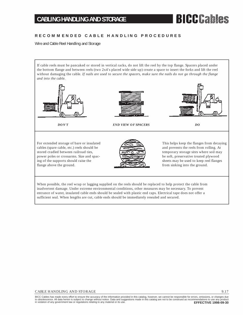
CABLING HANDLING AND STORAGE
CABLE HANDLING AND STORAGE 9.17BICC Cables has made every effort to ensure the accuracy of the information provided in this catalog, however, we cannot be responsible for errors, omissions, or changes dueto obsolescence. All data herein is subject to change without notice. Data and suggestions made in this catalog are not to be construed as recommendations to use any productin violation of any government law or regulations relating to any material or its use. EFFECTIVE 1998-09-30
R E C O M M E N D E D C A B L E H A N D L I N G P R O C E D U R E S
Wire and Cable Reel Handling and Storage
DON'T END VIEW OF SPACERS DO
If cable reels must be pancaked or stored in vertical racks, do not lift the reel by the top flange. Spacers placed underthe bottom flange and between reels (two 2x4's placed wide side up) create a space to insert the forks and lift the reelwithout damaging the cable. If nails are used to secure the spacers, make sure the nails do not go through the flangeand into the cable.
For extended storage of bare or insulatedcables (spare cable, etc.) reels should bestored cradled between railroad ties,power poles or crossarms. Size and spac-ing of the supports should raise theflange above the ground.
When possible, the reel wrap or lagging supplied on the reels should be replaced to help protect the cable frominadvertent damage. Under extreme environmental conditions, other measures may be necessary. To prevententrance of water, insulated cable ends should be sealed with plastic end caps. Electrical tape does not offer asufficient seal. When lengths are cut, cable ends should be immediately resealed and secured.
This helps keep the flanges from decayingand prevents the reels from rolling. Attemporary storage sites where soil maybe soft, preservative treated plywoodsheets may be used to keep reel flangesfrom sinking into the ground.
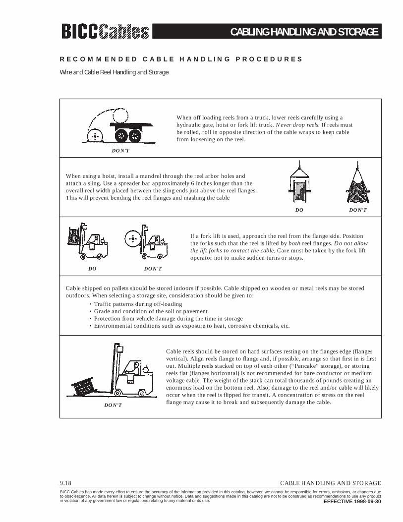
CABLING HANDLING AND STORAGE
9.18 CABLE HANDLING AND STORAGEBICC Cables has made every effort to ensure the accuracy of the information provided in this catalog, however, we cannot be responsible for errors, omissions, or changes dueto obsolescence. All data herein is subject to change without notice. Data and suggestions made in this catalog are not to be construed as recommendations to use any productin violation of any government law or regulations relating to any material or its use. EFFECTIVE 1998-09-30
R E C O M M E N D E D C A B L E H A N D L I N G P R O C E D U R E S
Wire and Cable Reel Handling and Storage
When off loading reels from a truck, lower reels carefully using ahydraulic gate, hoist or fork lift truck. Never drop reels. If reels mustbe rolled, roll in opposite direction of the cable wraps to keep cablefrom loosening on the reel.
When using a hoist, install a mandrel through the reel arbor holes andattach a sling. Use a spreader bar approximately 6 inches longer than theoverall reel width placed between the sling ends just above the reel flanges.This will prevent bending the reel flanges and mashing the cable
Cable shipped on pallets should be stored indoors if possible. Cable shipped on wooden or metal reels may be stored outdoors. When selecting a storage site, consideration should be given to:
• Traffic patterns during off-loading• Grade and condition of the soil or pavement• Protection from vehicle damage during the time in storage• Environmental conditions such as exposure to heat, corrosive chemicals, etc.
If a fork lift is used, approach the reel from the flange side. Positionthe forks such that the reel is lifted by both reel flanges. Do not allowthe lift forks to contact the cable. Care must be taken by the fork liftoperator not to make sudden turns or stops.
Cable reels should be stored on hard surfaces resting on the flanges edge (flangesvertical). Align reels flange to flange and, if possible, arrange so that first in is firstout. Multiple reels stacked on top of each other (“Pancake” storage), or storingreels flat (flanges horizontal) is not recommended for bare conductor or mediumvoltage cable. The weight of the stack can total thousands of pounds creating anenormous load on the bottom reel. Also, damage to the reel and/or cable will likelyoccur when the reel is flipped for transit. A concentration of stress on the reelflange may cause it to break and subsequently damage the cable.
DON'T
DO DON'T
DO DON'T
DON'T

MAXIMUM PULLING TENSION
CABLE HANDLING AND STORAGE 9.19BICC Cables has made every effort to ensure the accuracy of the information provided in this catalog, however, we cannot be responsible for errors, omissions, or changes dueto obsolescence. All data herein is subject to change without notice. Data and suggestions made in this catalog are not to be construed as recommendations to use any productin violation of any government law or regulations relating to any material or its use. EFFECTIVE 1998-09-30
Multiconductor cables having equal conductors; without subassemblies. Soft drawn copper.
The following maximum tensions are for direct attachment to the conductor. However, the pulling force must not exceed the smallest value of 1) conductor tension;or 2) pulling device tension; or 3) sidewall load.
AWG/kcmil#CDR 20 18 16 14 12 11 10 9
2 16 26 41 66 100 130 160 2003 24 39 62 99 150 190 240 3104 33 52 83 130 200 260 330 4105 41 65 100 160 260 320 410 5206 49 78 120 190 310 390 490 6207 49 78 120 190 310 390 490 6208 52 83 130 210 330 420 530 6709 59 93 140 230 370 470 590 75010 65 100 160 260 410 520 660 83011 72 110 180 280 460 570 730 92012 78 120 190 310 500 630 790 100013 85 130 210 340 540 680 860 100014 91 140 230 360 580 730 930 100015 98 150 240 390 620 790 990 100016 100 160 260 420 660 840 1000 100017 110 170 280 440 710 890 1000 100018 110 180 290 470 750 940 1000 100019 120 190 310 500 790 1000 1000 100020 130 200 330 520 830 1000 1000 100022 140 220 360 570 910 1000 1000 100024 150 240 390 630 1000 1000 1000 100026 170 270 420 680 1000 1000 1000 100028 180 290 460 730 1000 1000 1000 100030 190 310 490 780 1000 1000 1000 100032 200 330 520 840 1000 1000 1000 100034 220 350 560 890 1000 1000 1000 100036 230 370 590 940 1000 1000 1000 100038 240 390 620 1000 1000 1000 1000 100040 260 410 660 1000 1000 1000 1000 100042 270 430 690 1000 1000 1000 1000 100044 280 450 720 1000 1000 1000 1000 100046 300 470 760 1000 1000 1000 1000 100048 310 490 790 1000 1000 1000 1000 100050 320 510 820 1000 1000 1000 1000 1000
M A X I M U M A L L O W A B L E C O N D U C T O R T E N S I O N ( L B S )
T = 0.008 x CM x N, if N ≤ 6.T = 0.008 x CM x N x 0.8, if N > 6.T = 0.008 x CM x N x 0.6, if twisted subassemblies.

CABLE STORAGE
9.20 CABLE HANDLING AND STORAGEBICC Cables has made every effort to ensure the accuracy of the information provided in this catalog, however, we cannot be responsible for errors, omissions, or changes dueto obsolescence. All data herein is subject to change without notice. Data and suggestions made in this catalog are not to be construed as recommendations to use any productin violation of any government law or regulations relating to any material or its use. EFFECTIVE 1998-09-30
In general, the requirements for cable storage are quitestraight forward. Maintain the cable dry, at a temperaturethat will not cause degradation, and protect the cable from damage.
In order to maintain cable dryness, it is mandatory that thefollowing steps be taken:1. Maintain cable and end cap moisture seal integrity.2. Do not store in locations where standing water is likely.3. Maintain cable ends fixed to reel flanges without
puncturing jackets of end caps.
In order to keep the cable from degrading and ready foruse, it is necessary to:1. Maintain, as far as practicable, a covering over the cable
on the reel.2. Maintain storage temperatures between -20°C (-4°F)
and 50°C (122°F). Excursions beyond these tempera-tures are permissible for certain materials. Consult cable manufacturer.
3. It is recommended to avoid storing cables immediately
prior to installation in direct sunlight when ambienttemperatures are in excess of 122°F. Some jackets willsoften and this may lead to physical damage duringinstallation.
4. When cable is stored at temperatures colder than -20°C(-4°F), it is necessary to move the reel(s) into a heatedarea before installation, maintained at a minimum tem-perature of 32°F. The cable must reside in this heatedarea for at least 8 hours before it is installed.
In order to protect the cable from damage, it is necessary to:1. Store cable, especially long term storage, in relatively
inactive areas.2. Maintain a covering on the cable reels so that any cable
damaging instrument will damage the covering also.3. In areas of extreme rodent infestation, cables should
be protected with full lagging, steel plates over flangepenetrations or other suitable means.
4. Store cable reels standing on flange rims. DO NOT,except in special circumstances, store cable reels on theirsides; i.e., laying on one or the other flange.

CABLE PREINSTALLATION
CABLE INSTALLATION 9.21BICC Cables has made every effort to ensure the accuracy of the information provided in this catalog, however, we cannot be responsible for errors, omissions, or changes dueto obsolescence. All data herein is subject to change without notice. Data and suggestions made in this catalog are not to be construed as recommendations to use any productin violation of any government law or regulations relating to any material or its use. EFFECTIVE 1998-09-30
OverviewTo ensure safety during cable installa-tion and reliability once the cable isinstalled, you should confirm the fol-lowing prior to installation.• The cable selected is proper for
your application.• The cable has not been damaged in
transit or storage.
Review all applicable state and nationalcodes to verify that the cable chosen isappropriate for the job. Also, consultyour local building authority.
Next, you must identify any exist-ing cable damage and prevent any fur-ther damage from occurring. This isdone through proper cable inspection, handling and storage.
Cable InspectionInspect every cable reel for damagebefore accepting the shipment. Be particularly alert for cable damage if:• A reel is laying flat on its side• Several reels are stacked• Other freight is stacked on a reel• Nails have been driven into reel
flanges to secure shipping blocks• A reel flange is damaged• A cable covering is removed,
stained or damaged• A cable end seal is removed or
damaged• A reel has been dropped (hidden
damage likely)
Cabling HandlingRemove all nails and staples from the reel flanges before moving a reel,and avoid all objects that could crush,gouge or impact the cable when moving. NEVER use the cable as ameans to move a reel.
When unreeling, observe recom-mended bending radii, use swivels toprevent twisting and avoid overruns.
P R E I N S T A L L AT I O N

CABLE INSTALLATION
9.22 CABLE INSTALLATIONBICC Cables has made every effort to ensure the accuracy of the information provided in this catalog, however, we cannot be responsible for errors, omissions, or changes dueto obsolescence. All data herein is subject to change without notice. Data and suggestions made in this catalog are not to be construed as recommendations to use any productin violation of any government law or regulations relating to any material or its use. EFFECTIVE 1998-09-30
OverviewA survey of customer complaintsrevealed that 92% of the cables inquestion failed due to mechanicaldamage. When does mechanical dam-age usually occur? During installation.
In fact, most cables are subjected tomore mechanical stress during instal-lation than they ever experience inactual operation. Needless to say, han-dling and pulling your cable accordingto manufacturer’s recommendations isextremely important.
There are five main considerationsin any cable installation:• Ambient temperature• Equipment• Conduit fill• Mechanical fit in raceway• Physical limitations
These considerations were devel-oped and refined by installers ofpaper-lead cables. Two excellent refer-ences are the “Underground SystemsReference Book” and “Pipeline Designfor Pipe Type Feeders.” The formerwas published by Edison ElectricInstitute in 1931 and was last revisedin 1957. The latter was an AIEE paper (#53-389) by R.C. Rifenburg,published in Power Apparatus &Systems in December, 1953.
Ambient TemperatureLow temperatures are a cause for concern when installing cable. Thefollowing are temperatures belowwhich cable should not be installed.• CP/EP - 1/C.............................-31°F• CPE Jacket..............................-31°F• CPE/EP - 1/C ..........................-31°F• FREP, PE, XLPE - 1/C.............-58°F• PVC .......................................+14°F
CP = ChlorosulfonatedPolyethylene (Hypalon®)
CPE = Chlorinated PolyethyleneEP = Ethylene PropyleneFREP = Flame Retardant EPPVC = Polyvinyl Chloride
During cold weather installation,cable should be pulled more slowlyand trained in place the same day it isremoved from storage. Do not impact,drop, kink or bend cable sharply inlow temperatures.
EquipmentThe proper use of appropriate equip-ment is crucial to a successful cableinstallation. The equipment neededfor most installations is detailed in thefollowing checklist:
▫ Portable electric generator▫ Extension cords & GFCI▫ Pump, diaphragm▫ Make-up air blower & hose▫ Manhole cover hooks▫ Warning flags, signs▫ Electrostatic kV tester▫ Electric safety blankets and clamps▫ Radios or telephones▫ Gloves▫ Flood lamps▫ Fishtape or string blower/vacuum▫ Hand line▫ Duct cleaning mandrels▫ Duct testing mandrels▫ Capstan type puller▫ Snatch blocks▫ Short ropes for temp tie-offs▫ Guide-in flexible tubing
(elephant trunks)▫ Several wire rope slings of
various lengths▫ Shackles/clevis▫ Gang rollers; with at least 4 ft.
effective radius▫ Hand winches (come-a-long)▫ Manhole edge sheave▫ Pulling rope▫ Swivels▫ Basket grip pullers▫ 0-1/5/10 kip dynamometer▫ Reel arbor▫ Reel jacks▫ Reel brakes▫ Cable cutter▫ Lint free rags▫ Cable pulling lubricant▫ Prelubing devices▫ Plywood sheets▫ Diameter tape▫ 50 ft. measuring tape▫ Silicone caulking (to seal cable ends)
I N S T A L L AT I O N

CABLE INSTALLATION
CABLE INSTALLATION 9.23BICC Cables has made every effort to ensure the accuracy of the information provided in this catalog, however, we cannot be responsible for errors, omissions, or changes dueto obsolescence. All data herein is subject to change without notice. Data and suggestions made in this catalog are not to be construed as recommendations to use any productin violation of any government law or regulations relating to any material or its use. EFFECTIVE 1998-09-30
The following diagrams illustrate various cable feed-in setups.
C A B L E F E E D - I N S E T U P S
Reels on truck
Apply lube here
Guide-in tube
Setup for duct close to floor.
Setup for overhead, into tray.
Figure 1 Figure 2
IMPROPERPROPER
The feed-in setup shouldunreel the cable with a natural curvature (Figure1) as opposed to a reverse“S” curvature (Figure 2).
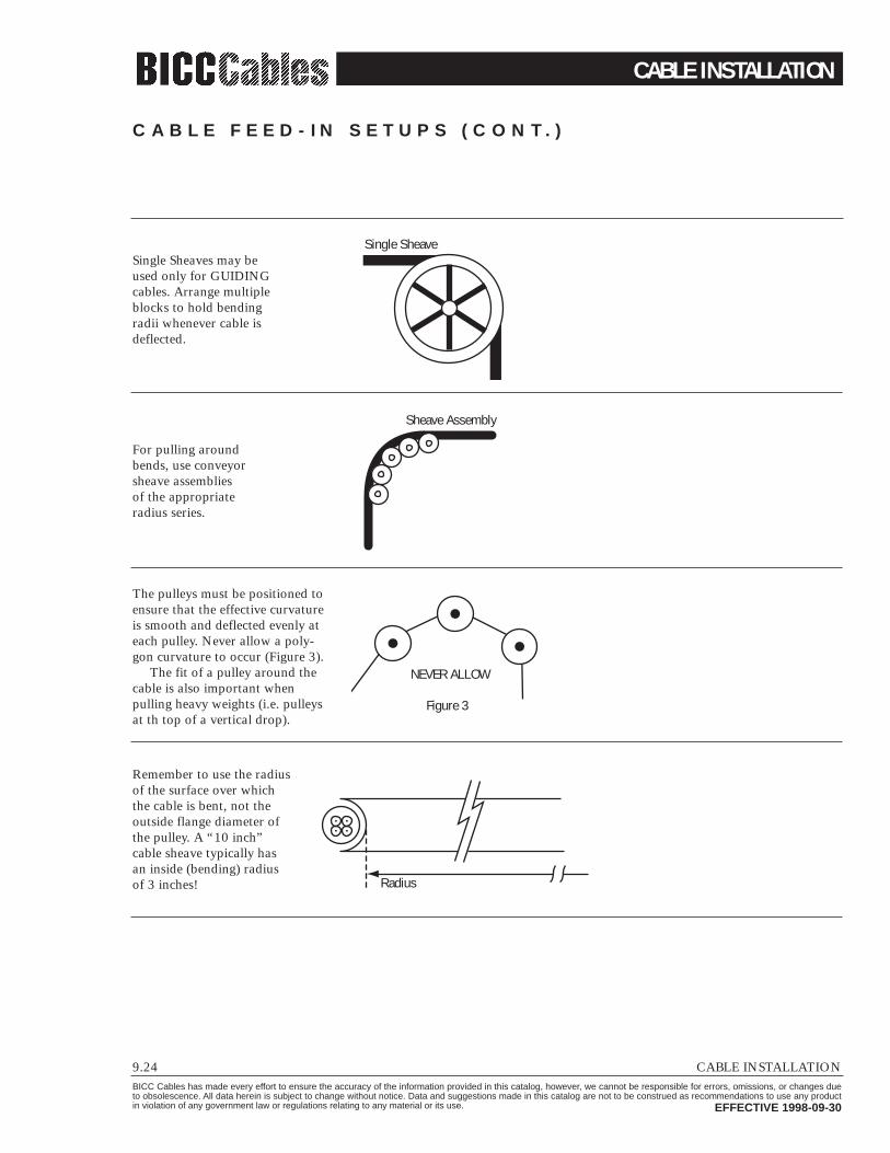
CABLE INSTALLATION
9.24 CABLE INSTALLATIONBICC Cables has made every effort to ensure the accuracy of the information provided in this catalog, however, we cannot be responsible for errors, omissions, or changes dueto obsolescence. All data herein is subject to change without notice. Data and suggestions made in this catalog are not to be construed as recommendations to use any productin violation of any government law or regulations relating to any material or its use. EFFECTIVE 1998-09-30
Single Sheave
Sheave Assembly
Figure 3
NEVER ALLOW
Radius
Remember to use the radiusof the surface over whichthe cable is bent, not theoutside flange diameter ofthe pulley. A “10 inch”cable sheave typically hasan inside (bending) radiusof 3 inches!
Single Sheaves may be used only for GUIDINGcables. Arrange multipleblocks to hold bendingradii whenever cable isdeflected.
For pulling aroundbends, use conveyorsheave assemblies of the appropriateradius series.
The pulleys must be positioned toensure that the effective curvatureis smooth and deflected evenly ateach pulley. Never allow a poly-gon curvature to occur (Figure 3).
The fit of a pulley around thecable is also important whenpulling heavy weights (i.e. pulleysat th top of a vertical drop).
C A B L E F E E D - I N S E T U P S ( C O N T. )

CABLE INSTALLATION
CABLE INSTALLATION 9.25BICC Cables has made every effort to ensure the accuracy of the information provided in this catalog, however, we cannot be responsible for errors, omissions, or changes dueto obsolescence. All data herein is subject to change without notice. Data and suggestions made in this catalog are not to be construed as recommendations to use any productin violation of any government law or regulations relating to any material or its use. EFFECTIVE 1998-09-30
The following maximum tensions are for direct attachment to the conductor. However, the pullingforce must not exceed the smallest value of 1) conductor tension; or 2) pulling device tension; or 3)sidewall load.
#CDRAWG/kcmil 1 2 3 4 5 6
20 8 16 24 26 33 3918 13 26 39 41 52 6216 21 41 62 66 83 9914 33 66 99 100 130 15012 52 100 150 160 200 25011 66 130 190 210 260 31010 83 160 240 260 330 3909 100 200 310 330 410 5008 130 260 390 420 520 6306 210 420 630 670 840 10004 330 660 1000 1060 1330 16003 420 840 1260 1340 1680 20202 530 1060 1590 1690 2120 25401 670 1330 2000 2140 2670 3210
1/0 840 1690 2530 2700 3370 40502/0 1060 2130 3190 3400 4250 51103/0 1340 2680 4020 4290 5370 64404/0 1690 3380 5070 5410 6500 6500250 2000 4000 6000 6400 6500 6500300 2400 4800 6500 6500 6500 6500350 2800 5600 6500 6500 6500 6500400 3200 6400 6500 6500 6500 6500450 3600 6500 6500 6500 6500 6500500 4000 6500 6500 6500 6500 6500600 4800 6500 6500 6500 6500 6500700 5000 6500 6500 6500 6500 6500750 5000 6500 6500 6500 6500 6500800 5000 6500 6500 6500 6500 6500900 5000 6500 6500 6500 6500 65001000 5000 6500 6500 6500 6500 6500
M A X I M U M A L L O W A B L E C O N D U C T O R T E N S I O N ( L B S )
T = 0.008 x CM x N, if N ≤ 3.T = 0.008 x CM x N x 0.8, if N > 3.
C O N D U C T O R S I N P A R A L L E L O R A S A S S E M B L I E S . S O F T D R A W N C O P P E R O R H A R D D R A W N A L U M I N U M .

CABLE INSTALLATION
9.26 CABLE INSTALLATIONBICC Cables has made every effort to ensure the accuracy of the information provided in this catalog, however, we cannot be responsible for errors, omissions, or changes dueto obsolescence. All data herein is subject to change without notice. Data and suggestions made in this catalog are not to be construed as recommendations to use any productin violation of any government law or regulations relating to any material or its use. EFFECTIVE 1998-09-30
M U LT I C O N D U C T O R C A B L E S H A V I N G E Q U A L S I Z E D C O N D U C T O R S ; W I T H O U T S U B A S S E M B L I E S .S O F T D R A W N C O P P E R .
AWG#CDR 20 18 16 14 12 11 10 9
2 16 26 41 66 100 130 160 2003 24 39 62 99 150 190 240 3104 33 52 83 130 200 260 330 4105 41 65 100 160 260 320 410 5206 49 78 120 190 310 390 490 6207 49 78 120 190 310 390 490 6208 52 83 130 210 330 420 530 6709 59 93 140 230 370 470 590 75010 65 100 160 260 410 520 660 83011 72 110 180 280 460 570 730 92012 78 120 190 310 500 630 790 100013 85 130 210 340 540 680 860 100014 91 140 230 360 580 730 930 100015 98 150 240 390 620 790 990 100016 100 160 260 420 660 840 1000 100017 110 170 280 440 710 890 1000 100018 110 180 290 470 750 940 1000 100019 120 190 310 500 790 1000 1000 100020 130 200 330 520 830 1000 1000 100022 140 220 360 570 910 1000 1000 100024 150 240 390 630 1000 1000 1000 100026 170 270 420 680 1000 1000 1000 100028 180 290 460 730 1000 1000 1000 100030 190 310 490 780 1000 1000 1000 100032 200 330 520 840 1000 1000 1000 100034 220 350 560 890 1000 1000 1000 100036 230 370 590 940 1000 1000 1000 100038 240 390 620 1000 1000 1000 1000 100040 260 410 660 1000 1000 1000 1000 100042 270 430 690 1000 1000 1000 1000 100044 280 450 720 1000 1000 1000 1000 100046 300 470 760 1000 1000 1000 1000 100048 310 490 790 1000 1000 1000 1000 100050 320 510 820 1000 1000 1000 1000 1000
M A X I M U M A L L O W A B L E C O N D U C T O R T E N S I O N ( L B S )
The maximum limit is 1000 lbs.
T = 0.008 x CM x N, if N ≤ 6.T = 0.008 x CM x N x 0.8, if N > 6.T = 0.008 x CM x N x 0.6, if twisted subassemblies.
The following maximum tensions are for direct attachment to the conductor. However, the pullingforce must not exceed the smallest value of 1) conductor tension; or 2) pulling device tension; or 3)sidewall load.

CABLE INSTALLATION
CABLE INSTALLATION 9.27BICC Cables has made every effort to ensure the accuracy of the information provided in this catalog, however, we cannot be responsible for errors, omissions, or changes dueto obsolescence. All data herein is subject to change without notice. Data and suggestions made in this catalog are not to be construed as recommendations to use any productin violation of any government law or regulations relating to any material or its use. EFFECTIVE 1998-09-30
OverviewTraining is the positioning of cablewhich is not under tension. Bending is the positioning of cable which isunder tension. When installing cable,the object is to limit these forces sothat the cable’s physical and electricalcharacteristics are maintained for the expected service life. The recom-mended limits are:• Tables per National Electric Code
(see tables at right)• Tables per ICEA/NEMA• A nonshielded cable can tolerate a
sharper bend than a shielded cablecan. This is especially true forcables having helical metal tapeswhich, when bent too sharply, canseparate, buckle and cut into theinsulation.
The problem is compounded by the factthat most tapes are under jackets whichconceal such damage. The shieldingbedding tapes or extruded polymershave sufficient conductivity and cover-age initially to pass acceptance testing,then fail prematurely due to corona atthe shield/insulation interface.
Remember that offsets are bends.
P H Y S I C A L L I M I T AT I O N S
T R A I N I N G A N D B E N D I N G
T A B L E 1Shielded or Lead-Covered Cable (Non-Armored)
Single and Multiple Conductor – All Voltages Over 600 Volt Nominal12 x Overall Diameter
T A B L E 3Armored Cable - Type MC
Interlocked or Corrugated SheathMultiple Conductors – Non Shielded
7 x External Diameter of ArmorMultiple Conductors – Shielded
12 x Diameter of One Shielded Conductoror
7 x External Diameter of ArmorWhichever is greater
T A B L E 2Non-Shielded and Non-Armored
Single and Multiple Conductor – All Voltages Over 600 Volt Nominal8 x Overall Diameter
Applications in Accordance with the National Electrical Code.
In all cases the minimum bending radius specified refers to the inner surface of thecable and not to axis of the cable.

CABLE INSTALLATION
9.28 CABLE INSTALLATIONBICC Cables has made every effort to ensure the accuracy of the information provided in this catalog, however, we cannot be responsible for errors, omissions, or changes dueto obsolescence. All data herein is subject to change without notice. Data and suggestions made in this catalog are not to be construed as recommendations to use any productin violation of any government law or regulations relating to any material or its use. EFFECTIVE 1998-09-30
OverviewSidewall load is the radial force exertedon a cable being pulled around a con-duit bend or sheave. Excessive sidewallloading can crush a cable and is, there-fore, one of the most restrictive factorsin installations having bends or hightensions. Sidewall loading is reduced by increasing the radius of the bends.
The maximum tension that can besafely applied to the cable duringinstallation can be derived using themaximum sidewall loading limit ofthe cable and the radius of the bend itis traversing. For example, a cablehaving a maximum SWL of 300 lb/ftthat is being pulled around a bendhaving a radius of 2 feet should haveno greater than 300 lbs/ft x 2 ft or
600 lbs tension applied to it as thecable exits the bend.
Laboratory tests conducted on standard cables after they had beensubjected to conduit pull tests through90° elbows of appropriate radii, indicate no significant change in thecable’s electrical parameters at the following sidewall loads:
M A X I M U M S I D E W A L L P R E S S U R ESidewall Loading (Sidewall Bearing Pressure)
Cable type SWL lbs/ft
600V nonshielded control 300
600V and 1 kV nonshielded EP power 500
5 and 35 kV UniShield® & Uniblend®, 5 kV Durasheath® EP 500
Interlocked armored cable (All Voltage Classes) 300Sidewall Load
Tension
Name of LubricantPolywater® A, G, and J...........................................................Polywater® Plus Silicone, Types NN, WNN, FS .....................Wire Lube® and Aqua-Gel® ....................................................Dyna-Blue® Cable Lubricant ..................................................Wirepull.................................................................................
ManufacturerAmerican Polywater Corporation, Stillwater, MNAmerican Polywater Corporation, Stillwater, MNIdeal Industries, Sycamore, ILAmerican Polywater Corporation, Stillwater, MNMac Products, Kearney, NJ
Other lubricants may be suitable for use with BICC Cable designs.Contact the lubricant manufacturer about the compatibility of their products with specific cables.Cable lubricants should be currently UL listed.Contact lubricant manufacturers for proof of approval.
B I C C C A B L E S A P P R O V A L L I S T
C A B L E P U L L I N G L U B R I C A N T S
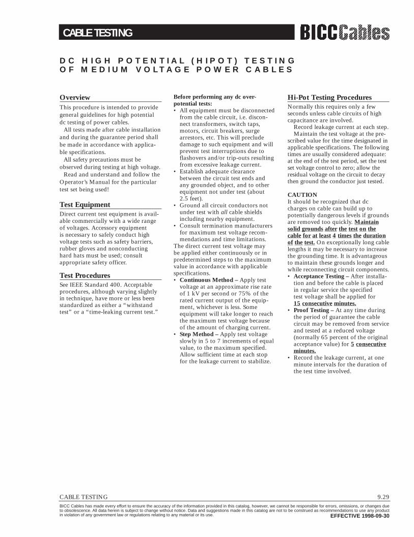
CABLE TESTING
CABLE TESTING 9.29BICC Cables has made every effort to ensure the accuracy of the information provided in this catalog, however, we cannot be responsible for errors, omissions, or changes dueto obsolescence. All data herein is subject to change without notice. Data and suggestions made in this catalog are not to be construed as recommendations to use any productin violation of any government law or regulations relating to any material or its use. EFFECTIVE 1998-09-30
OverviewThis procedure is intended to providegeneral guidelines for high potentialdc testing of power cables.
All tests made after cable installationand during the guarantee period shallbe made in accordance with applica-ble specifications.
All safety precautions must beobserved during testing at high voltage.
Read and understand and follow theOperator’s Manual for the particulartest set being used!
Test EquipmentDirect current test equipment is avail-able commercially with a wide rangeof voltages. Accessory equipment is necessary to safely conduct highvoltage tests such as safety barriers,rubber gloves and nonconductinghard hats must be used; consultappropriate safety officer.
Test ProceduresSee IEEE Standard 400. Acceptableprocedures, although varying slightlyin technique, have more or less beenstandardized as either a “withstandtest” or a “time-leaking current test.”
Before performing any dc over-potential tests:• All equipment must be disconnected
from the cable circuit, i.e. discon-nect transformers, switch taps,motors, circuit breakers, surgearrestors, etc. This will precludedamage to such equipment and willprevent test interruptions due toflashovers and/or trip-outs resultingfrom excessive leakage current.
• Establish adequate clearancebetween the circuit test ends andany grounded object, and to otherequipment not under test (about 2.5 feet).
• Ground all circuit conductors notunder test with all cable shieldsincluding nearby equipment.
• Consult termination manufacturersfor maximum test voltage recom-mendations and time limitations.
The direct current test voltage may be applied either continuously or inpredetermined steps to the maximumvalue in accordance with applicablespecifications.• Continuous Method – Apply test
voltage at an approximate rise rateof 1 kV per second or 75% of therated current output of the equip-ment, whichever is less. Someequipment will take longer to reachthe maximum test voltage becauseof the amount of charging current.
• Step Method – Apply test voltageslowly in 5 to 7 increments of equalvalue, to the maximum specified.Allow sufficient time at each stopfor the leakage current to stabilize.
Hi-Pot Testing ProceduresNormally this requires only a few seconds unless cable circuits of highcapacitance are involved.
Record leakage current at each step.Maintain the test voltage at the pre-
scribed value for the time designated inapplicable specifications. The followingtimes are usually considered adequate: at the end of the test period, set the testset voltage control to zero; allow theresidual voltage on the circuit to decaythen ground the conductor just tested.
CAUTIONIt should be recognized that dccharges on cable can build up topotentially dangerous levels if groundsare removed too quickly. Maintainsolid grounds after the test on thecable for at least 4 times the durationof the test. On exceptionally long cablelengths it may be necessary to increasethe grounding time. It is advantageousto maintain these grounds longer andwhile reconnecting circuit components.• Acceptance Testing – After installa-
tion and before the cable is placedin regular service the specified test voltage shall be applied for 15 consecutive minutes.
• Proof Testing – At any time duringthe period of guarantee the cablecircuit may be removed from serviceand tested at a reduced voltage(normally 65 percent of the originalacceptance value) for 5 consecutiveminutes.
• Record the leakage current, at oneminute intervals for the duration ofthe test time involved.
D C H I G H P O T E N T I A L ( H I P O T ) T E S T I N GO F M E D I U M V O LT A G E P O W E R C A B L E S

CABLE TESTING
9.30 CABLE TESTINGBICC Cables has made every effort to ensure the accuracy of the information provided in this catalog, however, we cannot be responsible for errors, omissions, or changes dueto obsolescence. All data herein is subject to change without notice. Data and suggestions made in this catalog are not to be construed as recommendations to use any productin violation of any government law or regulations relating to any material or its use. EFFECTIVE 1998-09-30
CommentsDC overpotential testing of mediumvoltage power cables is usually performed with negative polarity connected to the conductor.
DC overpotential testing is a toolonly for determining insulation resistance at higher voltages. Effectiveinsulation resistance of the cable system may be calculated by means ofOhms Law: R = V/I. The relation is:
Megohms = Kilovolts x 1000Microamperes
Insulation resistance may also be measured with standard instrumentswhich give a direct reading at 500volts (or higher, depending on themodel). IR in general has little or nodirect relationship to dielectric orbreakdown strength.
The significance of conducting dcHigh Voltage tests on nonshielded,nonmetallic-sheathed cable is depen-dent upon the environment in which itis installed because the characteristicsof the return circuits are unknown.The environment must be carefullyconsidered or test results may not besignificant. In fact, these tests can result in damage to the cable insulation.
Humidity, condensation and actualprecipitation on the surface of a cabletermination can increase the leakagecurrent by several orders of magnitude.Humidity also increases the coronacurrent, which indication is included inthe total leakage current. Wind preventsthe accumulation of space charges at allbare energized terminals. This resultsin an increase of corona. It is most
desirable to reduce or eliminate coronacurrent at the bare metal extremities of cable or terminations. This may beaccomplished by covering these areaswith plastic envelopes, plastic or glasscontainers, plastic wrap (e.g. “Saran”or “Handiwrap®”) or suitable electri-cal putty.
Routine periodic dc maintenancetesting of cable for the evaluation ofthe insulation strength is not a com-mon practice. Some power cable usershave adopted a program of testing circuits during planned outages, preferring possible breakdowns duringtesting rather than experiencing a service outage. It is nearly impossibleto recommend test voltage values forthose maintenance tests with the historyof the cable circuit. An arbitrary testvoltage level could break down a cablecircuit that would otherwise renderlong trouble-free service at normaloperating ac voltage.
The main usefulness of dc high voltage testing is to detect conductingparticles left on the creepage surfaceduring splicing or termination.
Test equipment should be suppliedfrom a stable, constant voltage source.Do not use the same source that issupplying arc welders or other equip-ment causing line voltage fluctuations.The output voltage of the test set mustbe filtered and regulated. Considerusing a portable motor driven alter-nator to energize test set.
The gradual decrease or nonincreaseof leakage current with respect to timeat maximum test voltage is the accep-tance criteria for dc hipot testing.
Testing ProblemsExtra Leakage Current:• Failure to guard against corona• Failure to clean insulation surface• Failure to keep cable ends dry• Failure to provide adequate
clearance to ground• Improper shield termination
Erratic Readings:• Fluctuating voltage to test set• Improper test leads
Environmental influences:• High relative humidity• Dampness, dew, fog• Wind, snow
Results vs. Cable LifeTo date there is no bases for correla-tion between dc test results and cablelife expectancy.
Partial Listing of Equipment SuppliersJ.G. Biddle CompanyBlue Bell, PA 19422
HipotronicsBrewster, NY 10519
Associated Research Inc.Chicago, IL 60648
Von CorporationBirmingham, AL 35211
D C H I G H P O T E N T I A L ( H I P O T ) T E S T I N GO F M E D I U M V O LT A G E P O W E R C A B L E S

CABLE TESTING
CABLE TESTING 9.31BICC Cables has made every effort to ensure the accuracy of the information provided in this catalog, however, we cannot be responsible for errors, omissions, or changes dueto obsolescence. All data herein is subject to change without notice. Data and suggestions made in this catalog are not to be construed as recommendations to use any productin violation of any government law or regulations relating to any material or its use. EFFECTIVE 1998-09-30
M A X I M U M D C T E S T V O LT A G E SF O R S H I E L D E D C A B L E S
EPR = NEMA WC-8, ICEA S-68-516XLP = NEMA WC-7, ICEA S-66-524PE = NEMA WC-5, ICEA S-61-402
National Electrical Manufacturers’ Association & IEEE Standard 400
RatedCircuit VoltagePhase to Phase Conductor Size
Volts AWG-kcmil
2001-5000 8-10005001-8000 6-10008001-15000 2-1000 (1)
1-1000 (1)15001-25000 1-100025001-28000 1-100028001-35000 1/0-1000
ACCEPTANCE100% 133%
(For Grounded) (For Ungrounded)kV kV25 2535 3555 –– 65 (2)
80 100 (2)85 _
100 _
(1) Combined in S-61-402, S-68-516 (2) Not in IEEE-400
BICC Cables does not make any recom-mendations for maintenance testing.
Test to be made immediately after installation.

CABLE TESTING
9.32 CABLE TESTINGBICC Cables has made every effort to ensure the accuracy of the information provided in this catalog, however, we cannot be responsible for errors, omissions, or changes dueto obsolescence. All data herein is subject to change without notice. Data and suggestions made in this catalog are not to be construed as recommendations to use any productin violation of any government law or regulations relating to any material or its use. EFFECTIVE 1998-09-30
During InstallationAt any time during installation, a dcproof test may be made at a voltagenot exceeding the dc test voltage specified in the table below, under the“During Installation” column, appliedfor 5 consecutive minutes.
In ServiceAfter the cable has been completelyinstalled and placed in service, a dcproof test may be made at any timewithin the first 5 years of service at a voltage not exceeding the dc testvoltage specified in the table belowunder the “First 5 Years” column, applied for 5 consecutive minutes.*
DC test voltages are applied to dis-cover gross problems such as improp-erly installed accessories or mechanicaldamage. DC testing is not expected to reveal deterioration due to agingduring the first five years of service.
T E S T S D U R I N G A N D A F T E R I N S T A L L AT I O N(Excerpt from AEIC CS6)
Rated Voltage Conductor Size Insulation ThicknessMaximum DC Field Test Voltages
Phase to Phase AWG or kcmil (mm2) Mils (mm)kV
During Installation First 5 Years100% 133% 100% 133% 100% 133%
5 8-1000 (8.4-507) 90 (2.92) 115 (2.92) 28 36 22 29Above 1000 (507) 140 (3.56) 140 (3.56) 28 36 22 29
8 6-1000 (13.3-507) 115 (2.92) 140 (3.56) 36 44 29 35Above 1000 (507) 175 (2.92) 140 (3.56) 36 44 29 35
15 2-1000 (33.6-507) 175 (4.45) 220 (5.59) 56 64 45 51Above 1000 (507) 220 (5.59) 220 (5.59) 56 64 45 51
25 1-2000 (42.4-1013) 260 (6.60) 320 (8.13) 80 96 64 7728 1-2000 (42.4-1013) 280 (7.11) 345 (8.76) 84 100 67 8035 1/0-2000 (53.5-1013) 345 (8.76) 420 (10.7) 100 124 80 9946 4/0-2000 (107.2-1013) 445 (11.3) 580 (14.7) 132 172 106 13869 500-2000 (153.4-1013) 650 (16.5) – 192 – 154 –
* These test voltages are for all EPR circuits. Other values may be dictatedby mixed cable circuits with other insulations or thinner insulation walls.

COMMON COLOR SEQUENCE
COMMON COLOR SEQUENCE 9.33BICC Cables has made every effort to ensure the accuracy of the information provided in this catalog, however, we cannot be responsible for errors, omissions, or changes dueto obsolescence. All data herein is subject to change without notice. Data and suggestions made in this catalog are not to be construed as recommendations to use any productin violation of any government law or regulations relating to any material or its use. EFFECTIVE 1998-09-30
C O M M O N C O L O R S E Q U E N C E
Conductor Background or Tracer Conductor Background or TracerNumber Base Color Color Number Base Color Color
SEQUENCE DESIGNATION K-11 Black — 12 Black White2 White — 13 Red White3 Red — 14 Green White4 Green — 15 Blue White5 Orange — 16 Black Red6 Blue — 17 White Red7 White Black 18 Orange Red8 Red Black 19 Blue Red9 Green Black 20 Red Green10 Orange Black 21 Orange Green11 Blue Black
SEQUENCE DESIGNATION K-2 (NEC)1 Black — 19 Orange Blue2 Red — 20 Yellow Blue3 Blue — 21 Brown Blue4 Orange — 22 Black Orange5 Yellow — 23 Red Orange6 Brown — 24 Blue Orange7 Red Black 25 Yellow Orange8 Blue Black 26 Brown Orange9 Orange Black 27 Black Yellow
10 Yellow Black 28 Red Yellow11 Brown Black 29 Blue Yellow12 Black Red 30 Orange Yellow13 Blue Red 31 Brown Yellow14 Orange Red 32 Black Brown15 Yellow Red 33 Red Brown16 Brown Red 34 Blue Brown17 Black Blue 35 Orange Brown18 Red Blue 36 Yellow Brown

METRIC CONVERSION
9.34 METRIC CONVERSIONBICC Cables has made every effort to ensure the accuracy of the information provided in this catalog, however, we cannot be responsible for errors, omissions, or changes dueto obsolescence. All data herein is subject to change without notice. Data and suggestions made in this catalog are not to be construed as recommendations to use any productin violation of any government law or regulations relating to any material or its use. EFFECTIVE 1998-09-30
M E T R I C C O N V E R S I O N
To Convert From To Multiply By
Inches Millimeters 25.4Millimeters Inches 0.03937
Inches Centimeters 2.54Centimeters Inches 0.3937
LengthFeet Meters 0.3048Meters Feet 3.2808
Kilofeet (1000 ft) Kilometers 0.3048Kilometers Kilofeet (1000 ft) 3.2808
Square Inches Square Millimeters 645.16Square Millimeters Square Inches 0.00155
Square Inches Square Centimeters 6.4516Square Centimeters Square Inches 0.155
Area Square Inches Circular Mils 1,273,240Circular Mils Square Inches 7.854 x 10⁻⁷
Circular Mils Square Millimeters 5.066 x 10⁴
Square Millimeters Circular Mils 1973.51
Square Feet Square Meters 0.0929Square Meters Square Feet 10.764
Pounds Kilograms 0.4536Weight Kilograms Pounds 2.2046
Pound/Kilofeet Kilograms/Kilometer 1.4882Kilograms/Kilometer Pounds/Kilofeet 0.6720
Ohms/Kilofeet Ohms/Kilometer 3.2808Ohms/Kilometer Ohms/Kilofeet 0.3048
Microfarads/Kilofeet Microfarads/Kilometer 3.2808Electrical Microfarads/Kilometer Microfarads/Kilofeet 0.3048
Insulation Resistance:Megohms—Kilofeet Megohms—Kilometer 0.3048Megohms—Kilometer Megohms—Kilofeet 3.2808
Pounds/Square Inch Kilo Pascal* 6.895Mechanical Kilo Pascal* Pounds/Square Inch 0.1432
Pounds (force) Newtons 4.448Newtons Pounds (force) 0.2248
* 1 Pascal = 1 newton/m2
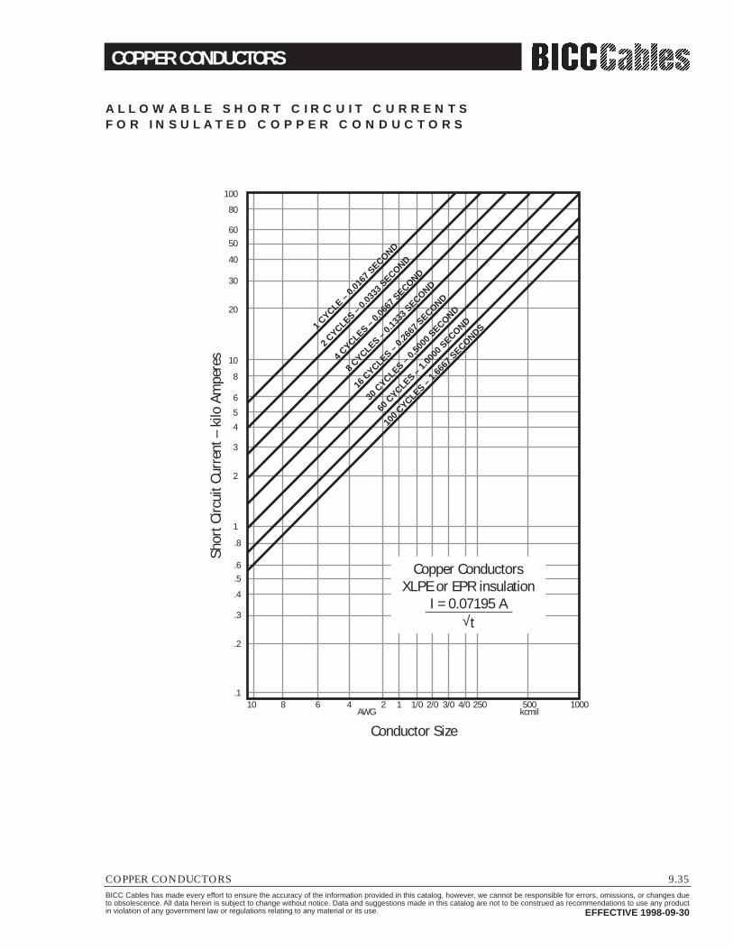
COPPER CONDUCTORS
COPPER CONDUCTORS 9.35BICC Cables has made every effort to ensure the accuracy of the information provided in this catalog, however, we cannot be responsible for errors, omissions, or changes dueto obsolescence. All data herein is subject to change without notice. Data and suggestions made in this catalog are not to be construed as recommendations to use any productin violation of any government law or regulations relating to any material or its use. EFFECTIVE 1998-09-30
A L L O W A B L E S H O R T C I R C U I T C U R R E N T SF O R I N S U L AT E D C O P P E R C O N D U C T O R S
10.1
.2
.3
.4
.5
.6
.8
1
2
3
4
5
6
8
10
20
30
40
5060
80
100
8 6 4 2 1 1/0 2/0 3/0 4/0 250 500kcmilAWG
1000
Conductor Size
Shor
t Circ
uit C
urre
nt –
kilo
Am
pere
s
1 CYCLE –
0.016
7 SECOND
2 CYCLES –
0.033
3 SECOND
4 CYCLES –
0.066
7 SECOND
100 C
YCLES – 1.6
667 S
ECONDS
60 C
YCLES – 1.0
000 S
ECOND
30 C
YCLES – 0.5
000 S
ECOND
16 C
YCLES – 0.2
667 S
ECOND
8 CYCLES –
0.133
3 SECOND
Copper ConductorsXLPE or EPR insulation
I = 0.07195 A√t

CONDUCTORS FOR GENERAL WIRING
9.36 CONDUCTORS FOR GENERAL WIRINGBICC Cables has made every effort to ensure the accuracy of the information provided in this catalog, however, we cannot be responsible for errors, omissions, or changes dueto obsolescence. All data herein is subject to change without notice. Data and suggestions made in this catalog are not to be construed as recommendations to use any productin violation of any government law or regulations relating to any material or its use. EFFECTIVE 1998-09-30
C O N D U C T O R D AT A
Size Diameter (Inches) Weight (lb/ft) Area
SolidClass B
Class H4Circumscribed
AWG kcmil 1Conc 2Combination 3Anapact™ Copper Aluminum in2
22 640 0.0253 0.00194 0.000589 0.00050320 1020 0.0320 0.036 0.003154 0.000942 0.0010318 1620 0.0403 0.046 0.005015 0.00149 0.0016316 2580 0.0508 0.058 0.007974 0.00238 0.0026114 4110 0.0641 0.073 0.01268 0.00378 0.0041412 6530 0.0808 0.092 0.02016 0.00601 0.0065810 10380 0.1019 0.116 0.03206 0.009556 0.01069 13090 0.1144 0.130 0.04042 0.01204 0.01338 16510 0.1285 0.146 0.137 0.167 0.05097 0.0152 0.01676 26240 0.1620 0.184 0.172 0.210 0.08105 0.0246 0.02664 41740 0.2043 0.232 0.217 0.266 0.1289 0.0392 0.04233 52620 0.2294 0.260 0.240 0.299 0.1625 0.04843 0.05312 66360 0.2576 0.292 0.271 0.335 0.2049 0.0623 0.06701 83690 0.2893 0.332 0.328 0.303 0.378 0.2584 0.0785 0.0865
1/0 105600 0.3249 0.373 0.369 0.342 0.424 0.3258 0.0991 0.1092/0 133100 0.3648 0.419 0.413 0.384 0.477 0.4109 0.1249 0.1383/0 167800 0.4096 0.470 0.464 0.429 0.536 0.5181 0.1575 0.1734/0 211600 0.4600 0.528 0.521 0.480 0.601 0.6533 0.1986 0.219
250 0.575 0.570 0.525 0.653 0.7719 0.2347 0.260300 0.630 0.574 0.716 0.9263 0.2816 0.312350 0.681 0.674 0.619 0.772 1.081 0.3286 0.364400 0.728 0.826 1.235 0.3755 0.416500 0.813 0.807 0.740 0.923 1.544 0.4694 0.519550 0.855 0.980 1.698 0.5163 0.574600 0.893 1.022 1.853 0.5632 0.626700 0.964 1.106 2.161 0.6571 0.730750 0.998 0.989 0.911 1.145 2.316 0.7040 0.782900 1.094 1.253 2.779 0.8449 0.940
1000 1.152 1.142 1.064 1.320 3.088 0.9387 1.04
1ASTM B 8 (Conc. = Concentric)2Combination Stranding, having smoother configuration than Class B.3Anapact is BICC Cables version of compact stranding.4Circumscribed Area = (π/4) (OD)2, using Class B OD’s, or OD of solid when Class B OD not given.
Use Circumscribed Area for computing conduit fill. Use in2 (π/4)(CM)(106) for finding conductor area. Values at 20°C (68°F)

CONDUCTORS FOR GENERAL WIRING
CONDUCTORS FOR GENERAL WIRING 9.37BICC Cables has made every effort to ensure the accuracy of the information provided in this catalog, however, we cannot be responsible for errors, omissions, or changes dueto obsolescence. All data herein is subject to change without notice. Data and suggestions made in this catalog are not to be construed as recommendations to use any productin violation of any government law or regulations relating to any material or its use. EFFECTIVE 1998-09-30
S I U N I T S / M E T R I C
Size Diameter (Inches) Weight (lb/ft) Area
SolidClass B
Class H4Circumscribed
AWG/kcmil mm21Conc 2Combination 3Anapact™ Copper Aluminum in2
22 0.32 0.64 2.89 0.87720 0.52 0.81 0.92 4.69 1.40 See Column 218 0.82 1.02 1.16 7.46 2.22 for sizes16 1.31 1.29 1.46 11.9 3.54 under 250 14 2.08 1.63 1.84 18.9 5.63 kcmil.12 3.31 2.05 2.32 30.0 8.9410 5.26 2.59 2.95 47.7 14.29 6.63 2.91 3.30 60.2 17.98 8.37 3.26 3.71 3.48 4.24 75.8 22.66 13.2 4.12 4.67 4.37 5.33 120 36.64 21.2 5.19 5.89 5.51 6.76 192 58.33 26.7 5.83 6.60 6.10 7.59 242 72.12 33.6 6.54 7.42 6.88 8.51 305 92.71 42.4 7.35 8.43 8.33 7.63 9.8 384 117
1/0 53.5 8.25 9.47 9.37 8.69 10.8 485 1472/0 67.4 9.27 10.6 10.5 9.75 12.1 611 1863/0 85 10.4 11.9 11.6 10.9 13.6 771 2344/0 107 11.7 13.4 13.2 12.2 15.3 972 296250 126 14.6 14.5 13.3 16.6 1150 349 168300 152 16.0 14.6 18.2 1380 419 201350 177 17.3 17.1 15.7 19.6 1610 489 235400 202 18.5 21.0 1840 559 269500 253 20.6 20.5 18.8 23.4 2300 698 335550 278 21.7 24.9 2530 768 371600 304 22.7 26.0 2760 838 404700 354 24.5 28.1 3220 978 471750 380 25.3 25.1 23.1 29.1 3450 1050 505900 456 27.8 31.6 4140 1280 607
1000 506 29.3 29 27 33.5 4600 1400 672
1(ASTM B 8) x (25.4) (Conc. = Concentric)2Combination Stranding, having smoother configuration than Class B.3Anapact is BICC Cables version of compact stranding.4Circumscribed Area = (π/4) (25.4)2, using Class B OD’s, or OD of solid when Class B OD not given.
Use Circumscribed Area for computing conduit fill. Values at 20°C (68°F)

JACKET & INSULATION MATERIALS
9.38 JACKET AND INSULATION MATERIALSBICC Cables has made every effort to ensure the accuracy of the information provided in this catalog, however, we cannot be responsible for errors, omissions, or changes dueto obsolescence. All data herein is subject to change without notice. Data and suggestions made in this catalog are not to be construed as recommendations to use any productin violation of any government law or regulations relating to any material or its use. EFFECTIVE 1998-09-30
T H E R M O P L A S T I C P R O P E R T I E SInsulation PVC Highor Jacket CPE Polyvinyl
Low Density CellularDensity
Poly- Poly-Nylon Teflon TPE
Material ChloridePolyethylene Polyethylene
PolyethyleneUrethane Propylene
Oxidation Resistance E E E E E E E E 0 E
Heat Resistance
G-E G-E G G-E E E G E 0 G
Oil Resistance
E E G-E G-E G-E E E E 0 P
Low Temp. Flexibility
G P-G G-E E E E G G 0 E
Weather, Sun Resistance
E G-E E E E E F-G E 0
Ozone Resistance E E E E E E E E E E
Abrasion Resistance
E F-G F-G G E F-G 0 E G-E F
Electrical Properties
F F-G E E E E P-F F E G
Flame Resistance
F E P P P P P P 0 F
Nuclear Radiation G-E P-F G G G F G F-G P-F FResistanceWater Resistance G E E E E E P P-F E E
Acid Resistance
G-E G-E G-E G-E G-E E F P-F E G
Alkali Resistance
G-E G-E G-E G-E G-E E F E E G
Gasoline, Kerosene, Etc. (Alaphatic F G-E P-F P-F P-F P-F F G E PHydrocarbons Resistance)Benzol, Toluol Etc. (Aromatic F P-F P P P P-F P G E PHydrocarbons Resistance)Degreaser Solvents (Halogenated P P-F P P P P P G E PHydrocarbons) ResistanceAlcohol Resistance
G G-E E E E E P P E E
P = PoorF = FairG = GoodE = ExcellentO = Outstanding
Any given property can usually be improved by the use of selective compounding.

JACKET & INSULATION MATERIALS
JACKET AND INSULATION MATERIALS 9.39BICC Cables has made every effort to ensure the accuracy of the information provided in this catalog, however, we cannot be responsible for errors, omissions, or changes dueto obsolescence. All data herein is subject to change without notice. Data and suggestions made in this catalog are not to be construed as recommendations to use any productin violation of any government law or regulations relating to any material or its use. EFFECTIVE 1998-09-30
T H E R M O S E T P R O P E R T I E S
InsulationSBR Hypalon NBR EPR
or Jacket(Styrene Natural Synthetic Poly (Chloro- (Nitrile or NBR/ (Ethylene
XLPE CPESilicone
MaterialButadiene Rubber Rubber Butadiene
NeopreneSulphonated Rubber PVC Propylene Rubber
Rubber Polyethylene Butadiene RubberNitrile
Oxidation Resistance F F G G G E F E G E E E
Heat Resistance F-G F F F G E G G E G E G
Oil Resistance P P P P G G G-E G F G G-E F-G
Low Temp.Flexibility F-G G E E F-G F F F G-E 0 F 0
Weather, SunResistance F F F F G E F-G G E G E 0
Ozone Resistance P P P P G E P G E E G-E 0
Abrasion Resistance G-E E E E G-E G G-E E G F-G G-E F
Electrical Properties E E E E F G P F E E F-G 0
Flame Resistance P P P P G G P G P F-G G F-G
Nuclear Radiation F-G F-G F-G P F-G G F-G P G E G EResistanceWater Resistance G-E G-E E E G G-E G-E E G-E G-E G-E G-E
Acid Resistance F-G F-G F-G F-G G E G G G-E G-E E F-G
Alkali Resistance F-G F-G F-G F-G G E F-G G G-E G-E E F-G
Gasoline, Kerosene, Etc. (Alaphatic P P P P G F E G-E P F F P-FHydrocarbons Resistance)Benzol, Toluol Etc. (Aromatic P P P P P-F F G G F F F PHydrocarbons Resistance)Degreaser Solvents (Halogenated P P P P P P-F P G P F P P-GHydrocarbons) ResistanceAlcohol Resistance F G G F-G F G E G P E G-E G
P = PoorF = FairG = GoodE = ExcellentO = Outstanding
Any given property can usually be improved by the use of selective compounding.

CHECKLIST FOR SPECIFICATIONS
9.40 CHECKLIST FOR SPECIFICATIONSBICC Cables has made every effort to ensure the accuracy of the information provided in this catalog, however, we cannot be responsible for errors, omissions, or changes dueto obsolescence. All data herein is subject to change without notice. Data and suggestions made in this catalog are not to be construed as recommendations to use any productin violation of any government law or regulations relating to any material or its use. EFFECTIVE 1998-09-30
Power Cable ▫ Size, AWG or kcmil▫ Conductor Type (metal)▫ Stranding
___ Class B, concentric___ Class B, compact___ Class C___ Other
▫ Bare/Coated ___ ▫ Conductor Shielding
___ Extruded___ Tape
▫ Insulation ___ EPR___ XLP___ PVC___ FR-EP___ Paper___ Other
▫ Insulation Level___ 100%___ 133%___ 173%
▫ Insulation Shielding___ Extruded___ Tape
▫ Metallic Shielding___ Helical copper tapes___ Helical wires___ Longitudinal drain wires___ Bare/Coated ___ ___ Other
▫ Jacket___ Neoprene___ CSPE___ PVC___ CPE___ Other
▫ Cable Assembly___ Cabled___ Multiconductor___ Other
▫ Grounding Conductors___ Quantity___ Insulated___ Size___ Bare/Coated ___
▫ Neutral Conductors___ Quantity___ Insulated___ Size___ Bare/Coated ___ Fillers___ Paper___ Flame retardant___ Fiber___ Other
▫ Covering___ Nonmetallic___ Interlocked armor___ Corrugated continuous
welded armor___ Lead___ Other
▫ Color▫ Voltage rating▫ Temperature rating▫ Approvals
Control Cable ▫ Conductor tape▫ AWG▫ Solid
___ Class B, concentric___ Flexible
▫ Bare/Coated ___ ▫ Insulation▫ Jacket▫ Temperature rating▫ Voltage rating▫ Individual Conductor Listings▫ Number of Conductors▫ Identification Method
___ Color code___ Numbering___ Tags
▫ Grounding___ Bare/Coated ___ ___ Size___ Insulated
General Checklist▫ Standards
___ UL___ ICEA___ AEIC___ IEEE___ Other
▫ Testing Procedures___ UL___ ICEA___ AEIC___ IEEE___ Other
▫ Special Requirements___ Flame retardant___ Sunlight resistant___ Oil resistant___ Direct burial___ Cold bend___ Other
▫ Documentation___ Certificates of Compliance___ Certified Test Reports___ Drawings___ Warranties___ Other
▫ System Characteristics▫ Shipping Details
___ Cut lengths___ Returnable reels___ Lagging___ Installation recommendation___ Other
▫ Identification___ Cable___ Reel___ Circuit
NOTE: This checklist must be accompanied by exact system detailsabout the environment and electricalcharacteristics.

CONDUCTORS FOR GENERAL WIRING
CABLE TESTING 9.41BICC Cables has made every effort to ensure the accuracy of the information provided in this catalog, however, we cannot be responsible for errors, omissions, or changes dueto obsolescence. All data herein is subject to change without notice. Data and suggestions made in this catalog are not to be construed as recommendations to use any productin violation of any government law or regulations relating to any material or its use. EFFECTIVE 1998-09-30
A M P A C I T I E S F O R P O R T A B L E P O W E R C A B L E S , A M P E R E S P E R C O N D U C T O R
Single Conductor Two Three Three Conductor Round Four Five SixPower Conductor Conductor Conductor Conductor Conductor
Conductor 2001- 8001- 15001- Round Round 0- 8001- 15001-Size 0-2000 8000 15000 25000 and Flat and Flat 8000 15000 25000
AWG or Volts Volts* Volts* Volts* 0-2000 0-5000 Volts Volts Volts Volts 0-2000 0-2000 0-2000kcmil Unshielded Shielded Shielded Shielded Volts Unshielded Shielded Shielded Shielded Volts Volts Volts
8 63 — — — 72 59 — — — 54 50 486 109 112 — — 95 79 93 — — 72 68 644 145 148 — — 127 104 122 — — 93 88 833 167 171 — — 145 120 140 — — 106 100 952 192 195 195 — 167 138 159 164 178 122 166 1101 223 225 225 222 191 161 184 187 191 143 136 129
1/0 258 260 259 255 217 186 211 215 218 165 — —2/0 298 299 296 293 250 215 243 246 249 192 — —3/0 345 345 343 337 286 249 279 283 286 221 — —4/0 400 400 397 389 328 287 321 325 327 255 — —250 445 444 440 430 363 320 355 359 360 280 — —300 500 496 491 480 400 357 396 — — 310 — —350 552 549 543 529 436 394 435 — — 335 — —400 600 596 590 572 470 430 470 — — 356 — —450 650 640 633 615 497 460 503 — — 377 — —500 695 688 678 659 524 487 536 — — 395 — —550 737 732 — — — — — — — — — —600 780 779 — — — — — — — — — —650 820 817 — — — — — — — — — —700 855 845 — — — — — — — — — —750 898 889 — — — — — — — — — —800 925 925 — — — — — — — — — —900 1010 996 — — — — — — — — — —1000 1076 1061 — — — — — — — — — —
* These ampacities are based on single isolated cable in air operated with open-circuit shield.
NOTE: These ampacities are based on a conductor temperature of 90°C and an ambient air temperature of 40°C.Copyright 1964 by the Insulated Cable Engineers Association (CEA). Permission has been granted by CEA to reproduce this material.

CONDUCTORS FOR GENERAL WIRING
9.42 CABLE TESTINGBICC Cables has made every effort to ensure the accuracy of the information provided in this catalog, however, we cannot be responsible for errors, omissions, or changes dueto obsolescence. All data herein is subject to change without notice. Data and suggestions made in this catalog are not to be construed as recommendations to use any productin violation of any government law or regulations relating to any material or its use. EFFECTIVE 1998-09-30
Reprinted with permission from NFPA 70-1996, the National Electrical Code ®, Copyright© 1995, National Fire Protection Association, Quincy, MA 02269. This reprinted materialis not the complete and official position of the National Fire Protection Agency, on the referenced subject which is represented only by the standard in its entirety.
A R T I C L E 3 1 0
Figure 310-1. Cable Installation Dimensions for Use with Tables 310-77 through 310-84.
Notes for all details:1. Minimum burial depths to top electrical ducts or cables shall be in accordance with
Section 300-5. Maximum depth to the top of electrical duct banks shall be 30 inchesand maximum depth to top of direct buried cables shall be 36 inches.
2. Burial depths shall be permitted to be increased in part(s) of the duct run to avoidunderground obstructions without decreasing the rated ampacity of the conductors.The total length of parts of the duct run increased in depth to avoid obstructions mustbe less than 25 percent of the total run length, or else the ampacity reduction factor ofNote 4 of Tables 310-69 through 310-84 shall be applied.
3. For SI units: one inch = 25.4 millimeters; one foot = 305 millimeters.
��yz ������yzz{||���������yyyyzz{{| ���������yyzzzz{||Detail 4
27" x 27"Electrical duct bankNine electrical ducts
Detail 319" x 27"
Electrical duct bankSix electrical ducts
Detail 219" x 19"
Electrical duct bankThree electrical ducts
Detail 111.5" x 11.5"
Electrical duct bankOne electrical duct
7.5"7.5" 7.5"
7.5"
7.5"
7.5"
7.5"
7.5"
7.5"
������yyz{{|27" x 19"
Electrical duct bankSix electrical ducts
27" x 11.5"Electrical duct bank
Three electrical ducts
7.5" 7.5"7.
5"������yzz{||
7.5" 7.5"
OR OR
Detail 5Buried
3 conductorcable
Detail 6Buried
3 conductorcables
Detail 7Buried
triplexed cables(1 circuit)
Detail 8Buried
triplexed cables(2 circuits)
Detail 9Buried single conductor
cables (1 circuit)
Detail 10Buried single conductor
cables (2 circuits)
7.5" 7.5" 7.5" 7.5" 7.5" 7.5"24"
24"24"
��{|LEGEND
Backfill(earth or concrete)
Electrical duct
Cable or cables
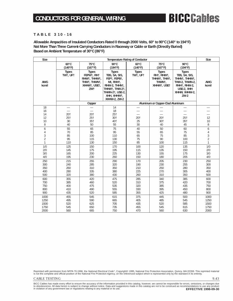
CONDUCTORS FOR GENERAL WIRING
CABLE TESTING 9.43BICC Cables has made every effort to ensure the accuracy of the information provided in this catalog, however, we cannot be responsible for errors, omissions, or changes dueto obsolescence. All data herein is subject to change without notice. Data and suggestions made in this catalog are not to be construed as recommendations to use any productin violation of any government law or regulations relating to any material or its use. EFFECTIVE 1998-09-30
Reprinted with permission from NFPA 70-1996, the National Electrical Code ®, Copyright© 1995, National Fire Protection Association, Quincy, MA 02269. This reprinted materialis not the complete and official position of the National Fire Protection Agency, on the referenced subject which is represented only by the standard in its entirety.
T A B L E 3 1 0 - 1 6
Allowable Ampacities of Insulated Conductors Rated 0 through 2000 Volts, 60° to 90°C (140° to 194°F)Not More Than Three Current-Carrying Conductors in Raceway or Cable or Earth (Directly Buried)Based on Ambient Temperature of 30°C (86°F)
Size Temperature Rating of Conductor Size60°C 75°C 90°C 60°C 75°C 90°C
(140°F) (167°F) (194°F) (140°F) (167°F) (194°F)Types Types Types Types Types Types
TW†, UF† FEPW†, RH† TBS, SA, SIS, TW†, UF† RH†, RHW†, TBS, SA, SIS,RHW†, THHW†, FEP†, FEPB†, THHW†, THW†, THHN†, THHW†,
AWG THW†, THWN†, MI, RHH†, THWN†, THW-2, THWN-2, AWGkcmil XHHW†, USE†, RHW-2, THHN†, XHHW†, USE† RHH†, RHW-2, kcmil
ZW† THHW†, THW-2†, USE-2, XHHTHWN-2†, USE-2, XHHW, XHHW-2,
XHH, XHHW†, ZW-2XHHW-2, ZW-2
Copper Aluminum or Copper-Clad Aluminum18 — — 14 — — — —16 — — 18 — — — —14 20† 20† 25† — — — —12 25† 25† 30† 20† 20† 25† 1210 30 35† 40† 25 30† 35† 108 40 50 55 30 40 45 86 55 65 75 40 50 60 64 70 85 95 55 65 75 43 85 100 110 65 75 85 32 95 115 130 75 90 100 21 110 130 150 85 100 115 1
1/0 125 150 170 100 120 135 1/02/0 145 175 195 115 135 150 2/03/0 165 200 225 130 155 175 3/04/0 195 230 260 150 180 205 4/0250 215 255 290 170 205 230 250300 240 285 320 190 230 255 300350 260 310 350 210 250 280 350400 280 335 380 225 270 305 400500 320 380 430 260 310 350 500600 355 420 475 285 340 385 600700 385 460 520 310 375 420 700750 400 475 535 320 385 435 750800 410 490 555 330 395 450 800900 435 520 585 355 425 480 9001000 455 545 615 375 445 500 10001250 495 590 665 405 485 545 12501500 520 625 705 435 520 585 15001750 545 650 735 455 545 615 17502000 560 665 750 470 560 630 2000

CONDUCTORS FOR GENERAL WIRING
9.44 CABLE TESTINGBICC Cables has made every effort to ensure the accuracy of the information provided in this catalog, however, we cannot be responsible for errors, omissions, or changes dueto obsolescence. All data herein is subject to change without notice. Data and suggestions made in this catalog are not to be construed as recommendations to use any productin violation of any government law or regulations relating to any material or its use. EFFECTIVE 1998-09-30
Reprinted with permission from NFPA 70-1996, the National Electrical Code ®, Copyright© 1995, National Fire Protection Association, Quincy, MA 02269. This reprinted materialis not the complete and official position of the National Fire Protection Agency, on the referenced subject which is represented only by the standard in its entirety.
Adjustment FactorsMore than Three Current-CarryingConductors in a Raceway or Cable.
Where the number of current-carrying conductors in a raceway orcable exceeds three, the allowableampacities shall be reduced as shownin the table below:
T A B L E 3 1 0 - 1 6 ( C O N T. )
Percent of Values inNumber of Tables asAdjusted for
Current-Carrying Ambient TemperatureConductors If Necessary4 through 6 807 through 9 70
10 through 20 5021 through 31 4531 through 40 4041 and above 35
Correction FactorsAmbient For ambient temperatures other than 30°C (86°F), multiply the allowable ampacities AmbientTemp. °C shown above by the appropriate factor shown below. Temp. °F
21-25 1.08 1.05 1.04 1.08 1.05 1.04 70-7726-30 1.00 1.00 1.00 1.00 1.00 1.00 78-8631-35 0.91 0.94 0.96 0.91 0.94 0.96 87-9536-40 0.82 0.88 0.91 0.82 0.88 0.91 96-10441-45 0.71 0.82 0.87 0.71 0.82 0.87 105-11346-50 0.58 0.75 0.82 0.58 0.75 0.82 114-12251-55 0.41 0.67 0.76 0.41 0.67 0.76 123-13156-60 — 0.58 0.71 — 0.58 0.71 132-14061-70 — 0.33 0.58 — 0.33 0.58 141-15871-80 — — 0.41 — — 0.41 159-176
† Unless otherwise specifically permitted elsewhere in this Code, the overcurrent protection for conductor types marked with an obelisk (†) shall not exceed15 amperes for No. 14, 20 amperes for No. 12, and 30 amperes for No. 10 copper; or 15 amperes for No. 12 and 25 amperes for No. 10 aluminum and copper-clad aluminum after any correction factors for ambient temperatures and number of conductors have been applied.

CONDUCTORS FOR GENERAL WIRING
CABLE TESTING 9.45BICC Cables has made every effort to ensure the accuracy of the information provided in this catalog, however, we cannot be responsible for errors, omissions, or changes dueto obsolescence. All data herein is subject to change without notice. Data and suggestions made in this catalog are not to be construed as recommendations to use any productin violation of any government law or regulations relating to any material or its use. EFFECTIVE 1998-09-30
Reprinted with permission from NFPA 70-1996, the National Electrical Code ®, Copyright© 1995, National Fire Protection Association, Quincy, MA 02269. This reprinted materialis not the complete and official position of the National Fire Protection Agency, on the referenced subject which is represented only by the standard in its entirety.
T A B L E 3 1 0 - 1 7
Allowable Ampacities of Single Insulated Conductors, Rated 0 through 2000 Volts in Free Air Based on Ambient Air Temperature of 30°C (86°F)
Size Temperature Rating of Conductor Size60°C 75°C 90°C 60°C 75°C 90°C
(140°F) (167°F) (194°F) (140°F) (167°F) (194°F)Types Types Types Types Types Types
TW†, UF† FEPW†, RH† TBS, SA, SIS, TW†, UF† RH†, RHW†, TBS, SA, SIS,RHW†, THHW†, FEP†, FEPB†, THHW†, THW†, THHN†, THHW†,
AWG THW†, THWN†, MI, RHH†, THWN†, THW-2, THWN-2, AWGkcmil XHHW†, RHW-2, THHN†, XHHW† RHH†, RHW-2, kcmil
ZW† THHW†, THW-2†, USE-2, XHH,THWN-2†, USE-2, XHHW†,
XHH, XHHW†, XHHW-2, ZW-2XHHW-2, ZW-2
Copper Aluminum or Copper-Clad Aluminum18 — — 18 — — — —16 — — 24 — — — —14 25† 30† 35† — — — —12 30† 35† 40† 25† 30† 35† 1210 40† 50† 55† 35 40† 40† 108 60 70 80 45 55 60 86 80 95 105 60 75 80 64 105 125 140 80 100 110 43 120 145 165 95 115 130 32 140 170 190 110 135 150 21 165 195 220 130 155 175 1
1/0 195 230 260 150 180 205 1/02/0 225 265 300 175 210 235 2/03/0 260 310 350 200 240 275 3/04/0 300 360 405 235 280 315 4/0250 340 405 455 265 315 355 250300 375 445 505 290 350 395 300350 420 505 570 330 395 445 350400 455 545 615 355 425 480 400500 515 620 700 405 485 545 500600 575 690 780 455 540 615 600700 630 755 855 500 595 675 700750 655 785 885 515 620 700 750800 680 815 920 535 645 725 800900 730 870 985 580 700 785 9001000 780 935 1055 625 750 845 10001250 890 1065 1200 710 855 960 12501500 980 1175 1325 795 950 1075 15001750 1070 1280 1445 875 1050 1185 17502000 1155 1385 1560 960 1150 1335 2000
Correction FactorsAmbient For ambient temperatures other than 30°C (86°F), multiply the allowable ampacities AmbientTemp. °C shown above by the appropriate factor shown below. Temp. °F
21-25 1.08 1.05 1.04 1.08 1.05 1.04 70-7726-30 1.00 1.00 1.00 1.00 1.00 1.00 78-8631-35 0.91 0.94 0.96 0.91 0.94 0.96 87-9536-40 0.82 0.88 0.91 0.82 0.88 0.91 96-10441-45 0.71 0.82 0.87 0.71 0.82 0.87 105-11346-50 0.58 0.75 0.82 0.58 0.75 0.82 114-12251-55 0.41 0.67 0.76 0.41 0.67 0.76 123-13156-60 — 0.58 0.71 — 0.58 0.71 132-14061-70 — 0.33 0.58 — 0.33 0.58 141-15871-80 — — 0.41 — — 0.41 159-176
† Unless otherwise specifically permitted elsewhere in this Code, the overcurrent protection for conductor types marked with an obelisk (†) shall not exceed15 amperes for No. 14, 20 amperes for No. 12, and 30 amperes for No. 10 copper; or 15 amperes for No. 12 and 25 amperes for No. 10 aluminum and copper-clad aluminum.

CONDUCTORS FOR GENERAL WIRING
9.46 CABLE TESTINGBICC Cables has made every effort to ensure the accuracy of the information provided in this catalog, however, we cannot be responsible for errors, omissions, or changes dueto obsolescence. All data herein is subject to change without notice. Data and suggestions made in this catalog are not to be construed as recommendations to use any productin violation of any government law or regulations relating to any material or its use. EFFECTIVE 1998-09-30
Reprinted with permission from NFPA 70-1996, the National Electrical Code ®, Copyright© 1995, National Fire Protection Association, Quincy, MA 02269. This reprinted materialis not the complete and official position of the National Fire Protection Agency, on the referenced subject which is represented only by the standard in its entirety.
T A B L E 3 1 0 - 6 7
Ampacities of Insulated Single Copper Conductor Cables Triplexed in Air Based on Conductor Temperature of 90°C (194°F) and 105°C (221°F) and Ambient Air Temperature of 40°C (104°F)
Temperature Rating of Conductor2001-5000 Volts 5001-35,000 Volts
Ampacity AmpacityConductor Size 90°C 105°C 90°C 105°C
AWG-kcmil (194°F) (221°F) (194°F) (221°F)Type Type Type Type
MV-90 MV-105 MV-90 MV-1058 65 74 — —6 90 99 100 1104 120 130 130 1402 160 175 170 1951 185 205 195 225
1/0 215 240 225 2552/0 250 275 260 2953/0 290 320 300 3404/0 335 375 345 390250 375 415 380 430350 465 515 470 525500 580 645 580 650750 750 835 730 8201000 880 980 850 950
T A B L E 3 1 0 - 6 9
Ampacities of Insulated Single Copper Conductor Isolated in Air Based on Conductor Temperature of 90°C (194°F) and 105°C (221°F) and Ambient Air Temperature of 40°C (104°F)
Temperature Rating of Conductor2001-5000 Volts 5001-15,000 Volts 15,001-35,000 Volts
Ampacity Ampacity AmpacityConductor Size 90°C 105°C 90°C 105°C 90°C 105°C
AWG-kcmil (194°F) (221°F) (194°F) (221°F) (194°F) (221°F)Type Type Type Type Type Type
MV-90 MV-105 MV-90 MV-105 MV-90 MV-1058 83 93 — — — —6 110 120 110 125 — —4 145 160 150 165 — —2 190 215 195 215 — —1 225 250 225 250 225 250
1/0 260 290 260 290 260 2902/0 300 330 300 335 300 3303/0 345 385 345 385 345 3804/0 400 445 400 445 395 445250 445 495 445 495 440 490350 550 615 550 610 545 605500 695 775 685 765 680 755750 900 1000 885 990 870 9701000 1075 1200 1060 1185 1040 11601250 1230 1370 1210 1350 1185 13201500 1365 1525 1345 1500 1315 14651750 1495 1665 1470 1640 1430 15952000 1605 1790 1575 1755 1535 1710

CONDUCTORS FOR GENERAL WIRING
CABLE TESTING 9.47BICC Cables has made every effort to ensure the accuracy of the information provided in this catalog, however, we cannot be responsible for errors, omissions, or changes dueto obsolescence. All data herein is subject to change without notice. Data and suggestions made in this catalog are not to be construed as recommendations to use any productin violation of any government law or regulations relating to any material or its use. EFFECTIVE 1998-09-30
T A B L E 3 1 0 - 7 1
Ampacities of an Insulated Three-Conductor Copper Cable Isolated in Air Based on Conductor Temperature of 90°C (194°F) and 105°C (221°F) and Ambient Air Temperature of 40°C (104°F)
Temperature Rating of Conductor2001-5000 Volts 5001-35,000 Volts
Ampacity AmpacityConductor Size 90°C 105°C 90°C 105°C
AWG-kcmil (194°F) (221°F) (194°F) (221°F)Type Type Type Type
MV-90 MV-105 MV-90 MV-1058 59 66 — —6 79 88 93 1054 105 115 120 1352 140 154 165 1851 160 180 185 210
1/0 185 205 215 2402/0 215 240 245 2753/0 250 280 285 3154/0 285 320 325 360250 320 355 360 400350 395 440 435 490500 485 545 535 600750 615 685 670 7451000 705 790 770 860
Reprinted with permission from NFPA 70-1996, the National Electrical Code ®, Copyright© 1995, National Fire Protection Association, Quincy, MA 02269. This reprinted materialis not the complete and official position of the National Fire Protection Agency, on the referenced subject which is represented only by the standard in its entirety.
T A B L E 3 1 0 - 7 3
Ampacities of an Insulated Triplexed or Three Single Conductor Copper Cables in Isolated Conduit in AirBased on Conductor Temperature of 90°C (194°F) and 105°C (221°F) and Ambient Air Temperature of 40°C (104°F)
Temperature Rating of Conductor2001-5000 Volts 5001-35,000 Volts
Ampacity AmpacityConductor Size 90°C 105°C 90°C 105°C
AWG-kcmil (194°F) (221°F) (194°F) (221°F)Type Type Type Type
MV-90 MV-105 MV-90 MV-1058 55 61 — —6 75 84 83 934 97 110 110 1202 130 145 150 1651 155 175 170 190
1/0 180 200 195 2152/0 205 225 225 2553/0 240 270 260 2904/0 280 305 295 330250 315 355 330 365350 385 430 395 440500 475 530 480 535750 600 665 585 6551000 690 770 675 755

CONDUCTORS FOR GENERAL WIRING
9.48 CABLE TESTINGBICC Cables has made every effort to ensure the accuracy of the information provided in this catalog, however, we cannot be responsible for errors, omissions, or changes dueto obsolescence. All data herein is subject to change without notice. Data and suggestions made in this catalog are not to be construed as recommendations to use any productin violation of any government law or regulations relating to any material or its use. EFFECTIVE 1998-09-30
Reprinted with permission from NFPA 70-1996, the National Electrical Code ®, Copyright© 1995, National Fire Protection Association, Quincy, MA 02269. This reprinted materialis not the complete and official position of the National Fire Protection Agency, on the referenced subject which is represented only by the standard in its entirety.
T A B L E 3 1 0 - 7 5
Ampacities of an Insulated Three-Conductor Copper Cable in Isolated Conduit in Air Based on Conductor Temperature of 90°C (194°F) and 105°C (221°F) and Ambient Air Temperature of 40°C (104°F)
Temperature Rating of Conductor2001-5000 Volts 5001-35,000 Volts
Ampacity AmpacityConductor Size 90°C 105°C 90°C 105°C
AWG-kcmil (194°F) (221°F) (194°F) (221°F)Type Type Type Type
MV-90 MV-105 MV-90 MV-1058 52 58 — —6 69 77 83 924 91 100 105 1202 125 135 145 1651 140 155 165 185
1/0 165 185 195 2152/0 190 210 220 2453/0 220 245 250 2804/0 255 285 290 320250 280 315 315 350350 350 390 385 430500 425 475 470 525750 525 585 570 6351000 590 660 650 725

CONDUCTORS FOR GENERAL WIRING
CABLE TESTING 9.49BICC Cables has made every effort to ensure the accuracy of the information provided in this catalog, however, we cannot be responsible for errors, omissions, or changes dueto obsolescence. All data herein is subject to change without notice. Data and suggestions made in this catalog are not to be construed as recommendations to use any productin violation of any government law or regulations relating to any material or its use. EFFECTIVE 1998-09-30
Reprinted with permission from NFPA 70-1996, the National Electrical Code ®, Copyright© 1995, National Fire Protection Association, Quincy, MA 02269. This reprinted materialis not the complete and official position of the National Fire Protection Agency, on the referenced subject which is represented only by the standard in its entirety.
T A B L E 3 1 0 - 7 7
Ampacities of Three Single Insulated Copper Conductors in Underground Electrical Ducts (Three Conductors per Electrical Duct) Based on Ambient Earth Temperature of 20°C (68°F), Electrical Duct Arrangement per Figure 310-1, 100 Percent Load Factor Thermal Resistance (RHO) of 90, Conductor Temperature of 90°C (194°F) and 105°C (221°F)
Temperature Rating of Conductor2001-5000 Volts 5001-35,000 Volts
Ampacity AmpacityConductor Size 90°C 105°C 90°C 105°C
AWG-kcmil (194°F) (221°F) (194°F) (221°F)Type Type Type Type
MV-90 MV-105 MV-90 MV-105One Circuit
(See Figure 310-1, Detail 1)8 64 69 — —6 85 92 90 974 110 120 115 1252 145 155 155 1651 170 180 175 185
1/0 195 210 200 2152/0 220 235 230 2453/0 250 270 260 2754/0 290 310 295 315250 320 345 325 345350 385 415 390 415500 470 505 465 500750 585 630 565 6101000 670 720 640 690
Three Circuit(See Figure 310-1, Detail 2)
8 56 60 — —6 73 79 77 834 95 100 99 1052 125 130 130 1351 140 150 145 155
1/0 160 175 165 1752/0 185 195 185 2003/0 210 225 210 2254/0 235 255 240 255250 260 280 260 280350 315 335 310 330500 375 405 370 395750 460 495 440 475
1000 525 565 495 535Six Circuit
(See Figure 310-1, Detail 3)8 48 52 — —6 62 67 64 684 80 86 82 882 105 110 105 1151 115 125 120 125
1/0 135 145 135 1452/0 150 160 150 1653/0 170 185 170 1854/0 195 210 190 205250 210 225 210 225350 250 270 245 265500 300 325 290 310750 365 395 350 3751000 410 445 390 415
For SI units: 1 in. = 25.4 mm.
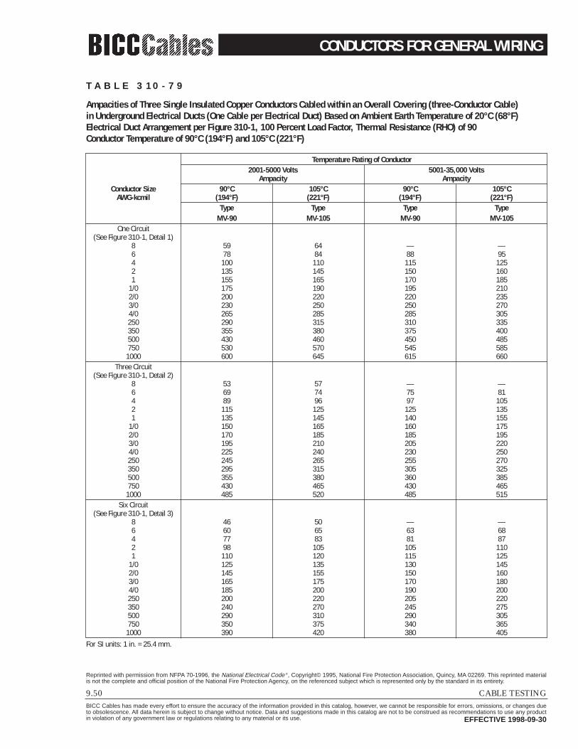
CONDUCTORS FOR GENERAL WIRING
9.50 CABLE TESTINGBICC Cables has made every effort to ensure the accuracy of the information provided in this catalog, however, we cannot be responsible for errors, omissions, or changes dueto obsolescence. All data herein is subject to change without notice. Data and suggestions made in this catalog are not to be construed as recommendations to use any productin violation of any government law or regulations relating to any material or its use. EFFECTIVE 1998-09-30
Reprinted with permission from NFPA 70-1996, the National Electrical Code ®, Copyright© 1995, National Fire Protection Association, Quincy, MA 02269. This reprinted materialis not the complete and official position of the National Fire Protection Agency, on the referenced subject which is represented only by the standard in its entirety.
T A B L E 3 1 0 - 7 9
Ampacities of Three Single Insulated Copper Conductors Cabled within an Overall Covering (three-Conductor Cable) in Underground Electrical Ducts (One Cable per Electrical Duct) Based on Ambient Earth Temperature of 20°C (68°F)Electrical Duct Arrangement per Figure 310-1, 100 Percent Load Factor, Thermal Resistance (RHO) of 90Conductor Temperature of 90°C (194°F) and 105°C (221°F)
Temperature Rating of Conductor2001-5000 Volts 5001-35,000 Volts
Ampacity AmpacityConductor Size 90°C 105°C 90°C 105°C
AWG-kcmil (194°F) (221°F) (194°F) (221°F)Type Type Type Type
MV-90 MV-105 MV-90 MV-105One Circuit
(See Figure 310-1, Detail 1)8 59 64 — —6 78 84 88 954 100 110 115 1252 135 145 150 1601 155 165 170 185
1/0 175 190 195 2102/0 200 220 220 2353/0 230 250 250 2704/0 265 285 285 305250 290 315 310 335350 355 380 375 400500 430 460 450 485750 530 570 545 5851000 600 645 615 660
Three Circuit(See Figure 310-1, Detail 2)
8 53 57 — —6 69 74 75 814 89 96 97 1052 115 125 125 1351 135 145 140 155
1/0 150 165 160 1752/0 170 185 185 1953/0 195 210 205 2204/0 225 240 230 250250 245 265 255 270350 295 315 305 325500 355 380 360 385750 430 465 430 465
1000 485 520 485 515Six Circuit
(See Figure 310-1, Detail 3)8 46 50 — —6 60 65 63 684 77 83 81 872 98 105 105 1101 110 120 115 125
1/0 125 135 130 1452/0 145 155 150 1603/0 165 175 170 1804/0 185 200 190 200250 200 220 205 220350 240 270 245 275500 290 310 290 305750 350 375 340 3651000 390 420 380 405
For SI units: 1 in. = 25.4 mm.

CONDUCTORS FOR GENERAL WIRING
CABLE TESTING 9.51BICC Cables has made every effort to ensure the accuracy of the information provided in this catalog, however, we cannot be responsible for errors, omissions, or changes dueto obsolescence. All data herein is subject to change without notice. Data and suggestions made in this catalog are not to be construed as recommendations to use any productin violation of any government law or regulations relating to any material or its use. EFFECTIVE 1998-09-30
Reprinted with permission from NFPA 70-1996, the National Electrical Code ®, Copyright© 1995, National Fire Protection Association, Quincy, MA 02269. This reprinted materialis not the complete and official position of the National Fire Protection Agency, on the referenced subject which is represented only by the standard in its entirety.
T A B L E 3 1 0 - 8 1
Ampacities of Single Insulated Copper Conductors Directly Buried in Earth Based on Ambient Earth Temperature of 20°C (68°F), Arrangement per Figure 310-1, 100 Percent Load FactorThermal Resistance (RHO) of 90, Conductor Temperature of 90°C (194°F) and 105°C (221°F)
Temperature Rating of Conductor2001-5000 Volts 5001-35,000 Volts
Ampacity AmpacityConductor Size 90°C 105°C 90°C 105°C
AWG-kcmil (194°F) (221°F) (194°F) (221°F)Type Type Type Type
MV-90 MV-105 MV-90 MV-105One Circuit — 3 Conductors(See Figure 310-1, Detail 9)
8 110 115 — —6 140 150 130 1404 180 195 170 1802 230 250 210 2251 260 280 240 260
1/0 295 320 275 2952/0 335 365 310 3353/0 385 415 355 3804/0 435 465 405 435250 470 510 440 475350 570 615 535 575500 690 745 650 700750 845 910 805 8651000 980 1055 930 1005
Two Circuits — 6 Conductors(See Figure 310-1, Detail 10)
8 100 110 — —6 130 140 120 1304 165 180 160 1702 215 230 195 2101 240 260 225 240
1/0 275 295 255 2752/0 310 335 290 3153/0 355 380 330 3554/0 400 430 375 405250 435 470 410 440350 520 560 495 530500 630 680 600 645750 775 835 740 7951000 890 960 855 920
For SI units: 1 in. = 25.4 mm.

CONDUCTORS FOR GENERAL WIRING
9.52 CABLE TESTINGBICC Cables has made every effort to ensure the accuracy of the information provided in this catalog, however, we cannot be responsible for errors, omissions, or changes dueto obsolescence. All data herein is subject to change without notice. Data and suggestions made in this catalog are not to be construed as recommendations to use any productin violation of any government law or regulations relating to any material or its use. EFFECTIVE 1998-09-30
Reprinted with permission from NFPA 70-1996, the National Electrical Code ®, Copyright© 1995, National Fire Protection Association, Quincy, MA 02269. This reprinted materialis not the complete and official position of the National Fire Protection Agency, on the referenced subject which is represented only by the standard in its entirety.
T A B L E 3 1 0 - 8 3
Ampacities of Three Insulated Copper Conductors Cabled within an Overall Covering (Three-Conductor Cable)Directly Buried in Earth, Based on Ambient Earth Temperature of 20°C (68°F), Electrical Duct Arrangement per Figure 310-1100 Percent Load Factor, Thermal Resistance (RHO) of 90, Conductor Temperature of 90°C (194°F) and 105°C (221°F)
Temperature Rating of Conductor2001-5000 Volts 5001-35,000 Volts
Ampacity AmpacityConductor Size 90°C 105°C 90°C 105°C
AWG-kcmil (194°F) (221°F) (194°F) (221°F)Type Type Type Type
MV-90 MV-105 MV-90 MV-105One Circuit—
(See Figure 310-1, Detail 5)8 85 89 — —6 105 115 115 1204 135 150 145 1552 180 190 185 2001 200 215 210 225
1/0 230 245 240 2552/0 260 280 270 2903/0 295 320 305 3304/0 335 360 350 375250 365 395 380 410350 440 475 460 495500 530 570 550 590750 650 700 665 7201000 730 785 750 810
Two Circuits—(See Figure 310-1, Detail 10)
8 80 84 — —6 100 105 105 1154 130 140 135 1452 165 180 170 1851 185 200 195 210
1/0 215 230 220 2352/0 240 260 250 2703/0 275 295 280 3054/0 310 335 320 345250 340 365 350 375350 410 440 420 450500 490 525 500 535750 595 640 605 6501000 665 715 675 730
For SI units: 1 in. = 25.4 mm.
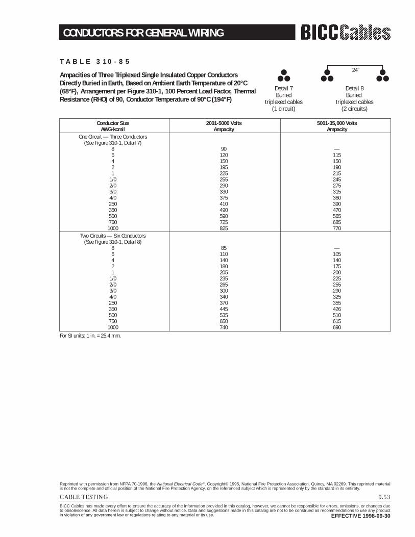
CONDUCTORS FOR GENERAL WIRING
CABLE TESTING 9.53BICC Cables has made every effort to ensure the accuracy of the information provided in this catalog, however, we cannot be responsible for errors, omissions, or changes dueto obsolescence. All data herein is subject to change without notice. Data and suggestions made in this catalog are not to be construed as recommendations to use any productin violation of any government law or regulations relating to any material or its use. EFFECTIVE 1998-09-30
Reprinted with permission from NFPA 70-1996, the National Electrical Code ®, Copyright© 1995, National Fire Protection Association, Quincy, MA 02269. This reprinted materialis not the complete and official position of the National Fire Protection Agency, on the referenced subject which is represented only by the standard in its entirety.
T A B L E 3 1 0 - 8 5
Ampacities of Three Triplexed Single Insulated Copper ConductorsDirectly Buried in Earth, Based on Ambient Earth Temperature of 20°C(68°F), Arrangement per Figure 310-1, 100 Percent Load Factor, ThermalResistance (RHO) of 90, Conductor Temperature of 90°C (194°F)
Conductor Size 2001-5000 Volts 5001-35,000 VoltsAWG-kcmil Ampacity Ampacity
One Circuit — Three Conductors(See Figure 310-1, Detail 7)
8 90 —6 120 1154 150 1502 195 1901 225 215
1/0 255 2452/0 290 2753/0 330 3154/0 375 360250 410 390350 490 470500 590 565750 725 6851000 825 770
Two Circuits — Six Conductors(See Figure 310-1, Detail 8)
8 85 —6 110 1054 140 1402 180 1751 205 200
1/0 235 2252/0 265 2553/0 300 2904/0 340 325250 370 355350 445 426500 535 510750 650 6151000 740 690
For SI units: 1 in. = 25.4 mm.
Detail 7Buried
triplexed cables(1 circuit)
Detail 8Buried
triplexed cables(2 circuits)
24"

CONDUCTORS FOR GENERAL WIRING
9.54 CABLE TESTINGBICC Cables has made every effort to ensure the accuracy of the information provided in this catalog, however, we cannot be responsible for errors, omissions, or changes dueto obsolescence. All data herein is subject to change without notice. Data and suggestions made in this catalog are not to be construed as recommendations to use any productin violation of any government law or regulations relating to any material or its use. EFFECTIVE 1998-09-30
Reprinted with permission from NFPA 70-1996, the National Electrical Code ®, Copyright© 1995, National Fire Protection Association, Quincy, MA 02269. This reprinted materialis not the complete and official position of the National Fire Protection Agency, on the referenced subject which is represented only by the standard in its entirety.
T A B L E B - 3 1 0 - 1
Ampacities of Two or Three Insulated Conductors, Rated 0 through 2000 Volts within an Overall Covering(Multiconductor Cable), in Raceway, in Free Air, Based on Ambient Air Temperature of 30°C (86°F)
Temperature Rating of ConductorSize 60°C 75°C 90°C 60°C 75°C 90°C Size
(140°F) (167°F) (194°F) (140°F) (167°F) (194°F)Types Types Types Types Types Types
TW, UF RH, RHW THHN, THHW, TW RH, RHW, THHN, THHW,THHW, THW THW-2, THWN-2, THHW, THW, THW-2, THWN-2,
AWG THWN, RHH, RWH-2, THWN, RHH†, RWH-2, AWGkcmil XHHW, USE-2, XHHW XHHW USE-2, XHHW, kcmil
ZW XHHW-2, ZW-2 XHHW-2, ZW-2
Copper Aluminum or Copper-Clad Aluminum14 16† 18† 21† — — — —12 20† 24† 27† 16† 18† 21† 1210 27† 33† 36† 21† 25† 28† 108 36 43 48 28 33 37 86 48 58 65 38 45 51 64 66 79 89 51 61 69 43 76 90 102 59 70 79 32 88 105 119 69 83 93 21 102 121 137 80 95 106 1
1/0 121 145 163 94 113 127 1/02/0 138 166 186 108 129 146 2/03/0 158 189 214 124 147 167 3/04/0 187 223 253 147 176 197 4/0250 205 245 276 160 192 217 250300 234 281 317 185 221 250 300350 255 305 345 202 242 273 350400 274 328 371 218 261 295 400500 315 378 427 254 303 342 500600 343 413 468 279 335 378 600700 376 452 514 310 371 420 700750 387 466 529 321 384 435 750800 397 479 543 331 397 450 800900 415 500 570 350 421 477 9001000 448 542 617 382 460 521 1000
Correction FactorsAmbient For ambient temperatures other than 30°C (86°F), multiply the allowable ampacities AmbientTemp. °C shown above by the appropriate factor shown below. Temp. °F
21-25 1.08 1.05 1.04 1.08 1.05 1.04 70-7726-30 1.00 1.00 1.00 1.00 1.00 1.00 79-8631-35 0.91 0.94 0.96 0.91 0.94 0.96 88-9536-40 0.82 0.88 0.91 0.82 0.88 0.91 97-10441-45 0.71 0.82 0.87 0.71 0.82 0.87 106-11346-50 0.58 0.75 0.82 0.58 0.75 0.82 115-12251-55 0.41 0.67 0.76 0.41 0.67 0.76 124-13156-60 — 0.58 0.71 — 0.58 0.71 133-14061-70 — 0.33 0.58 — 0.33 0.58 142-15871-80 — — 0.41 — — 0.41 160-176
† Unless otherwise specifically permitted elsewhere in this Code, the overcurrent protection for conductor types marked with an obelisk (†) shall not exceed15 amperes for No. 14, 20 amperes for No. 12, and 30 amperes for No. 10 copper; or 15 amperes for No. 12 and 25 amperes for No. 10 aluminum and copper-clad aluminum.

CONDUCTORS FOR GENERAL WIRING
CABLE TESTING 9.55BICC Cables has made every effort to ensure the accuracy of the information provided in this catalog, however, we cannot be responsible for errors, omissions, or changes dueto obsolescence. All data herein is subject to change without notice. Data and suggestions made in this catalog are not to be construed as recommendations to use any productin violation of any government law or regulations relating to any material or its use. EFFECTIVE 1998-09-30
Reprinted with permission from NFPA 70-1996, the National Electrical Code ®, Copyright© 1995, National Fire Protection Association, Quincy, MA 02269. This reprinted materialis not the complete and official position of the National Fire Protection Agency, on the referenced subject which is represented only by the standard in its entirety.
T A B L E B - 3 1 0 - 2
Ampacities of Two or Three Single Insulated Conductors, Rated 0 through 2000 VoltsSupported on a Messenger, Based on Ambient Air Temperature of 40°C (104°F)
Size Temperature Rating of Conductor Size75°C (167°F) 90°C (194°F) 75°C (167°F) 90°C (194°F)
TYPES TYPES TYPES TYPESRH, RHW THHN, THHW RH, RHW THHN, THHW
AWG THHW, THW THW-2, THWN-2, THW, THWN, RHH, XHHW AWGkcmil THWN, RHH, RWH-2, THHW, RHW-2, kcmil
XHHW, ZW USE-2, XHHW, XHHW XHHW-2,XHHW-2, ZW-2 THW-2, THWN-2,
USE-2, ZW-28 57 66 44 51 86 76 89 59 69 64 101 117 78 91 43 118 138 92 107 32 135 158 106 123 21 158 185 123 144 1
1/0 183 214 143 167 1/02/0 212 247 165 193 2/03/0 245 287 192 224 3/04/0 287 335 224 262 4/0250 320 374 251 292 250300 359 419 282 328 300350 397 464 312 364 350400 430 503 339 395 400500 496 580 392 458 500600 553 647 440 514 600700 610 714 488 570 700750 638 747 512 598 750800 660 773 532 622 800900 704 826 572 669 9001000 748 879 612 716 1000
Ambient For ambient temperatures other than 40°C (104°F), multiply the AmbientTemp. °C ampacities show above by the appropriate factor shown below. Temp °F
21-25 1.20 1.14 1.20 1.14 70-7726-30 1.13 1.10 1.13 1.10 79-8631-35 1.07 1.05 1.07 1.05 88-9536-40 1.00 1.00 1.00 1.00 97-10441-45 0.93 0.95 0.93 0.95 106-11346-50 0.85 0.89 0.85 0.89 115-12251-55 0.76 0.84 0.76 0.84 124-13156-60 0.65 0.77 0.65 0.77 133-14061-70 0.38 0.63 0.38 0.63 142-15871-80 — 0.45 — 0.45 160-176

CONDUCTORS FOR GENERAL WIRING
9.56 CABLE TESTINGBICC Cables has made every effort to ensure the accuracy of the information provided in this catalog, however, we cannot be responsible for errors, omissions, or changes dueto obsolescence. All data herein is subject to change without notice. Data and suggestions made in this catalog are not to be construed as recommendations to use any productin violation of any government law or regulations relating to any material or its use. EFFECTIVE 1998-09-30
Reprinted with permission from NFPA 70-1996, the National Electrical Code ®, Copyright© 1995, National Fire Protection Association, Quincy, MA 02269. This reprinted materialis not the complete and official position of the National Fire Protection Agency, on the referenced subject which is represented only by the standard in its entirety.
T A B L E B - 3 1 0 - 3
Ampacities of Multiconductor Cables with Not More than Three Insulated Conductors, Rated 0 through 2000 Volts in Free AirBased on Ambient Air Temperature of 40°C (104°F) (For TC, MC, MI, UF, and USE Cables)
Size Temperature Rating of Conductor Size
AWG60°C 75°C 85°C 90°C 60°C 75°C 85°C 90°C
AWGkcmil
(140°F) (167°F) (185°F) (194°F) (140°F) (167°F) (185°F) (194°F)kcmil
Copper Aluminum or Copper-Clad Aluminum18 11† 1816 16† 1614 18† 21† 24† 25† 1412 21† 28† 30† 32† 18† 21† 24† 25† 1210 28† 36† 41† 43† 21† 28† 30† 32† 108 39 50 56 59 30 39 44 46 86 52 68 75 79 41 53 59 61 64 69 89 100 104 54 70 78 81 43 81 104 116 121 63 81 91 95 32 92 118 132 138 72 92 103 108 21 107 138 154 161 84 108 120 126 1
1/0 124 160 178 186 97 125 139 145 1/02/0 143 184 206 215 111 144 160 168 2/03/0 165 213 238 249 129 166 185 194 3/04/0 190 245 274 287 149 192 214 224 4/0250 212 274 305 320 166 214 239 250 250300 237 306 341 357 186 240 268 280 300350 261 337 377 394 205 265 296 309 350400 281 363 406 425 222 287 317 334 400500 321 416 465 487 255 330 368 385 500600 354 459 513 538 284 368 410 429 600700 387 502 562 589 306 405 462 473 700750 404 523 586 615 328 424 473 495 750800 415 539 604 633 339 439 490 513 800900 438 570 639 670 362 469 514 548 9001000 461 601 674 707 385 499 558 584 1000
Ambient For ambient temperatures other than 30°C (86°F), multiply the AmbientTemp. °C ampacities shown above by the appropriate factor shown below. Temp °F
21-25 1.32 1.20 1.15 1.14 1.32 1.20 1.15 1.14 70-7726-30 1.22 1.13 1.11 1.10 1.22 1.13 1.11 1.10 79-8631-35 1.12 1.07 1.05 1.05 1.12 1.07 1.05 1.05 88-9536-40 1.00 1.00 1.00 1.00 1.00 1.00 1.00 1.00 97-10441-45 0.87 0.93 0.94 0.95 0.87 0.93 0.94 0.95 106-11346-50 0.71 0.85 0.88 0.89 0.71 0.85 0.88 0.89 115-12251-55 0.50 0.76 0.82 0.84 0.50 0.76 0.82 0.84 124-13156-60 — 0.65 0.75 0.77 — 0.65 0.75 0.77 133-14061-70 — 0.38 0.58 0.63 — 0.38 0.58 0.63 142-15871-80 — — 0.33 0.44 — — 0.33 0.44 160-176
† Unless otherwise specifically permitted elsewhere in this Code, the overcurrent protection for conductor types marked with an obelisk (†) shall not exceed15 amperes for No. 14, 20 amperes for No. 12, and 30 amperes for No. 10 copper; or 15 amperes for No. 12 and 25 amperes for No. 10 aluminum and copper-clad aluminum.

CONDUCTORS FOR GENERAL WIRING
CABLE TESTING 9.57BICC Cables has made every effort to ensure the accuracy of the information provided in this catalog, however, we cannot be responsible for errors, omissions, or changes dueto obsolescence. All data herein is subject to change without notice. Data and suggestions made in this catalog are not to be construed as recommendations to use any productin violation of any government law or regulations relating to any material or its use. EFFECTIVE 1998-09-30
Reprinted with permission from NFPA 70-1996, the National Electrical Code ®, Copyright© 1995, National Fire Protection Association, Quincy, MA 02269. This reprinted materialis not the complete and official position of the National Fire Protection Agency, on the referenced subject which is represented only by the standard in its entirety.
T A B L E B - 3 1 0 - 8
Ampacities of Two or Three Insulated Conductors, Rated 0 through 2000 Volts, Cabled within an Overall (Two- or Three-Conductor) Covering, Directly Buried in Earth, Based on Ambient Air Temperature of 20°C (68°F) Arrangement per Figure B-310-2, 100 Percent Load Factor, Thermal Resistance (Rho) of 90.
Size Temperature Rating of Conductor Size1 Cable 2 Cables 1 Cable 2 Cables
(Fig. B310-2, (Fig. B310-2, (Fig. B310-2, (Fig. B310-2,Detail 5) Detail 6) Detail 5) Detail 6)
60°C 75°C 60°C 75°C 60°C 75°C 60°C 75°C(140°F) (167°F) (140°F) (167°F) (140°F) (167°F) (140°F) (167°F)
AWG Types Types AWGkcmil RHW, RHW RHW, RHW, kcmil
THHW, THHW, THHW, THHWTHW, THW THW, THW,
UF THWN, UF THWN, UF THWN, UF THWN,XHHW, SHHW, XHHW, XHHW,
USE USE USE USECopper Aluminum or Copper-Clad Aluminum
8 64 75 60 70 51 59 47 55 86 85 100 81 95 68 75 60 70 64 107 125 100 117 83 97 78 91 42 137 161 128 150 107 126 110 117 21 155 182 145 170 121 142 113 132 1
1/0 177 208 165 193 138 162 129 151 1/02/0 201 236 188 220 157 184 146 171 2/03/0 229 269 213 250 179 210 166 195 3/04/0 259 304 241 282 203 238 188 220 4/0250 333 308 261 241 250350 401 370 315 290 350500 481 442 381 350 500750 585 535 473 433 7501000 657 600 545 497 1000
Ambient For ambient temperatures other than 20°C (68°F), multiply the AmbientTemp. °C ampacities shown above by the appropriate factor shown below. Temp °F
6-10 1.12 1.09 1.12 1.09 1.12 1.09 1.12 1.09 43-5011-15 1.06 1.04 1.04 1.04 1.06 1.04 1.06 1.04 52-5916-20 1.00 1.00 1.00 1.00 1.00 1.00 1.00 1.00 61-6821-25 0.94 0.95 0.94 0.95 0.94 0.95 0.94 0.95 70-7726-30 0.87 0.90 0.87 0.90 0.87 0.90 0.87 0.90 79-86
For ampacities of UF cable in underground electrical ducts, multiply the ampacities shown in the table by 0.74.

CONDUCTORS FOR GENERAL WIRING
9.58 CABLE TESTINGBICC Cables has made every effort to ensure the accuracy of the information provided in this catalog, however, we cannot be responsible for errors, omissions, or changes dueto obsolescence. All data herein is subject to change without notice. Data and suggestions made in this catalog are not to be construed as recommendations to use any productin violation of any government law or regulations relating to any material or its use. EFFECTIVE 1998-09-30
Reprinted with permission from NFPA 70-1996, the National Electrical Code ®, Copyright© 1995, National Fire Protection Association, Quincy, MA 02269. This reprinted materialis not the complete and official position of the National Fire Protection Agency, on the referenced subject which is represented only by the standard in its entirety.
T A B L E B - 3 1 0 - 9
Ampacities of Three Triplexed Single Insulated Conductors, Rated 0 through 2000 Volts, Directly Buried in EarthBased on Ambient Earth Temperature of 20°C (68°F), Arrangement per Figure B-310-2, 100 Percent Load Factor,Thermal Resistance (Rho) of 90.
Size Temperature Rating of Conductor SizeSee See See See
(Fig. B310-2, (Fig. B310-2, (Fig. B310-2, (Fig. B310-2,Detail 7) Detail 8) Detail 7) Detail 8)
AWG 60°C 75°C 60°C 75°C 60°C 75°C 60°C 75°C AWGkcmil (140°F) (167°F) (140°F) (167°F) (140°F) (167°F) (140°F) (167°F) kcmil
Types TypesUF USE UF USE UF USE UF USE
Copper Aluminum or Copper-Clad Aluminum8 72 84 66 77 55 65 51 60 86 91 107 84 99 72 84 66 77 64 119 139 109 128 92 108 85 100 42 153 179 140 164 119 139 109 128 21 173 203 159 186 135 158 124 145 1
1/0 197 231 181 212 154 180 141 165 1/02/0 223 262 205 240 175 205 159 187 2/03/0 254 298 232 272 199 233 181 212 3/04/0 289 339 263 308 226 265 206 241 4/0250 370 336 289 263 250350 445 403 349 316 350500 536 483 424 382 500750 654 587 525 471 7501000 744 665 608 544 1000
Ambient For ambient temperatures other than 20°C (68°F), multiply the AmbientTemp. °C ampacities shown above by the appropriate factor shown below. Temp °F
6-10 1.12 1.09 1.12 1.09 1.12 1.09 1.12 1.09 43-5011-15 1.06 1.04 1.06 1.04 1.06 1.04 1.06 1.04 52-5916-20 1.00 1.00 1.00 1.00 1.00 1.00 1.00 1.00 61-6821-25 0.94 0.95 0.94 0.95 0.94 0.95 0.94 0.95 70-7726-30 0.87 0.90 0.87 0.90 0.87 0.90 0.87 0.90 79-86
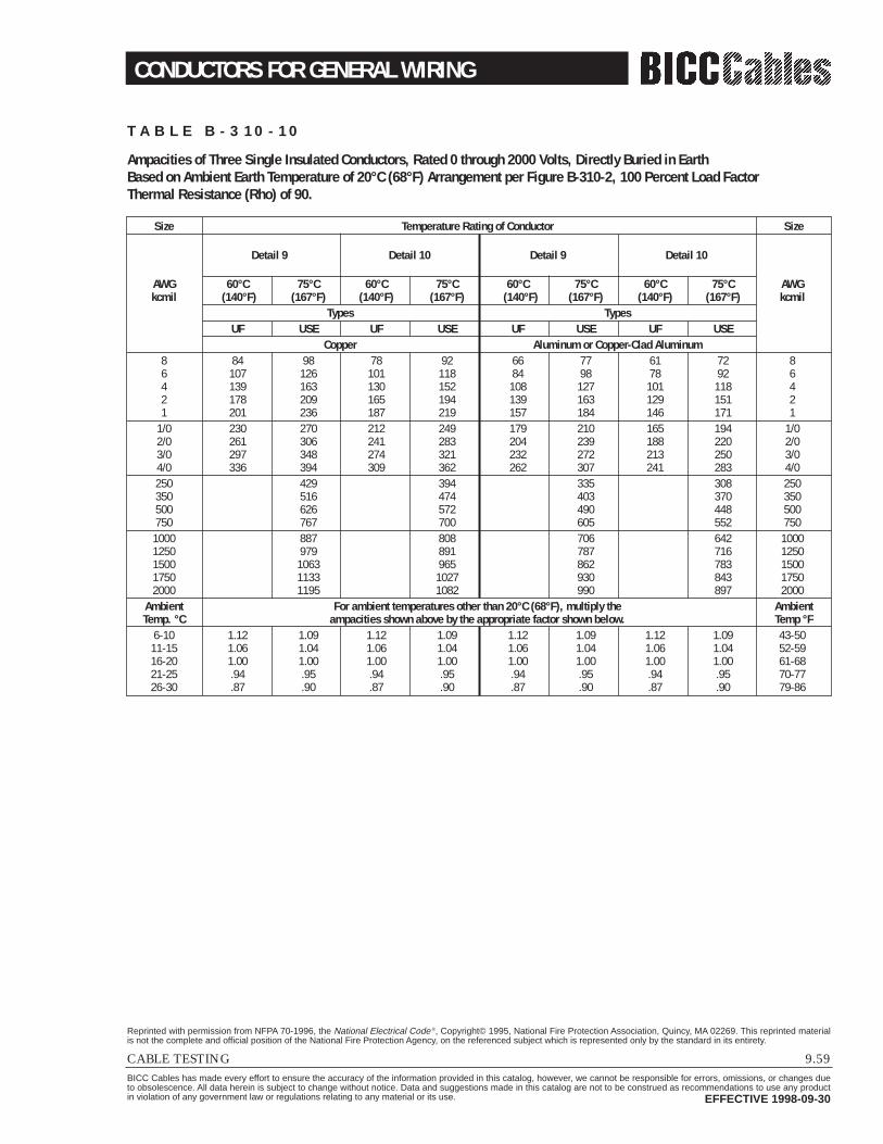
CONDUCTORS FOR GENERAL WIRING
CABLE TESTING 9.59BICC Cables has made every effort to ensure the accuracy of the information provided in this catalog, however, we cannot be responsible for errors, omissions, or changes dueto obsolescence. All data herein is subject to change without notice. Data and suggestions made in this catalog are not to be construed as recommendations to use any productin violation of any government law or regulations relating to any material or its use. EFFECTIVE 1998-09-30
Reprinted with permission from NFPA 70-1996, the National Electrical Code ®, Copyright© 1995, National Fire Protection Association, Quincy, MA 02269. This reprinted materialis not the complete and official position of the National Fire Protection Agency, on the referenced subject which is represented only by the standard in its entirety.
T A B L E B - 3 1 0 - 1 0
Ampacities of Three Single Insulated Conductors, Rated 0 through 2000 Volts, Directly Buried in EarthBased on Ambient Earth Temperature of 20°C (68°F) Arrangement per Figure B-310-2, 100 Percent Load FactorThermal Resistance (Rho) of 90.
Size Temperature Rating of Conductor Size
Detail 9 Detail 10 Detail 9 Detail 10
AWG 60°C 75°C 60°C 75°C 60°C 75°C 60°C 75°C AWGkcmil (140°F) (167°F) (140°F) (167°F) (140°F) (167°F) (140°F) (167°F) kcmil
Types TypesUF USE UF USE UF USE UF USE
Copper Aluminum or Copper-Clad Aluminum8 84 98 78 92 66 77 61 72 86 107 126 101 118 84 98 78 92 64 139 163 130 152 108 127 101 118 42 178 209 165 194 139 163 129 151 21 201 236 187 219 157 184 146 171 1
1/0 230 270 212 249 179 210 165 194 1/02/0 261 306 241 283 204 239 188 220 2/03/0 297 348 274 321 232 272 213 250 3/04/0 336 394 309 362 262 307 241 283 4/0250 429 394 335 308 250350 516 474 403 370 350500 626 572 490 448 500750 767 700 605 552 7501000 887 808 706 642 10001250 979 891 787 716 12501500 1063 965 862 783 15001750 1133 1027 930 843 17502000 1195 1082 990 897 2000
Ambient For ambient temperatures other than 20°C (68°F), multiply the AmbientTemp. °C ampacities shown above by the appropriate factor shown below. Temp °F
6-10 1.12 1.09 1.12 1.09 1.12 1.09 1.12 1.09 43-5011-15 1.06 1.04 1.06 1.04 1.06 1.04 1.06 1.04 52-5916-20 1.00 1.00 1.00 1.00 1.00 1.00 1.00 1.00 61-6821-25 .94 .95 .94 .95 .94 .95 .94 .95 70-7726-30 .87 .90 .87 .90 .87 .90 .87 .90 79-86

HIGH TEMP LEAD WIRE AMPACITIES
9.60 CABLE TESTINGBICC Cables has made every effort to ensure the accuracy of the information provided in this catalog, however, we cannot be responsible for errors, omissions, or changes dueto obsolescence. All data herein is subject to change without notice. Data and suggestions made in this catalog are not to be construed as recommendations to use any productin violation of any government law or regulations relating to any material or its use. EFFECTIVE 1998-09-30
Wire Size, Number of ConductorsAWG or MCM 1 2 to 3 4 to 6 7 to 24
16 40 29 23 2014 53 39 31 2712 70 49 39 3410 93 66 53 468 121 86 69 606 160 114 92 804 210 153 122 1072 279 200 160 1401 326 234 188 164
1/0 375 270 215 1892/0 434 313 250 2193/0 503 362 290 2544/0 583 420 335 294250 648 467 374 327350 805 574 458 402500 1012 708 566 495750 1310 894 715 6251000 1563 1030 825 721
T Y P E T G G T & T K G T
The following Ampacity data is based onIPCEA P-46-426 criteria for appropriatelydesigned cables for use at elevated tem-peratures. These values were extrapolatedfrom the appropriate 90°C maximum conductor temperature tables to cover thedesignated, higher conductor temperaturethat appears below.
Conditions:1. Conductor – 27% NCC
(Nickel Clad Copper)2. Single or multi-conductor
cable in free air3. Maximum conductor temperature
of 250°C4. Ambient temperature of 30°C
Other Conditions:
1) For single and multi-conductor cables in single conduit, in air: New Ampacity = 0.89 X any Ampacity in Table
2) For duplexed or triplexed single conductor cables in air: New Ampacity = 0.82 X single conductor Ampacity from Table
3) For duplexed or triplexed single conductor cables in single conduit, in air:New Ampacity = 0.68 X single conductor from Table
4) For randomly spaced cables in trays, use the Ampacity from above Table corresponding to the number of loaded conductors in the tray
For more than 24 conductors in a tray:• 24 to 42 conductors
New Ampacity = 0.60 X 2 or 3 conductor Ampacity from Table
• 43 and upNew Ampacity = 0.50 X 2 or 3 conductor Ampacity from Table
5) Correction factors from ambients other than 30°C, when the maximum conductor temperature is 250°C
60°C .93 Times Ampacity in Table80°C .88
100°C .82125°C .75150°C .67200°C .48255°C .33

HIGH TEMP LEAD WIRE AMPACITIES
CABLE TESTING 9.61BICC Cables has made every effort to ensure the accuracy of the information provided in this catalog, however, we cannot be responsible for errors, omissions, or changes dueto obsolescence. All data herein is subject to change without notice. Data and suggestions made in this catalog are not to be construed as recommendations to use any productin violation of any government law or regulations relating to any material or its use. EFFECTIVE 1998-09-30
Wire Size, Number of Conductors
AWG 1 2 to 3 4 to 6
18 26 20 1516 34 25 2014 45 30 2512 65 45 4010 85 60 458 110 75 556 135 90 794 185 120 952 245 160 1251 285 190 150
1/0 330 220 1802/0 385 255 2003/0 440 290 2304/0 525 345 275
T Y P E M G
The ampacity table below applies to appropriately designed 450°C rated TypeMG Appliance Wires, and IntegraflameControl Cables.
Conditions:1. 27 percent nickel plated copper
conductors per ASTM B3552. Single conductor in free air, sufficiently
removed from any heat source3. Maximum conductor temperature
of 450°C4. Ambient temperature of 30°C
Correction factors for ambient temperatures over 30°C:80°C 0.94
125°C 0.88150°C 0.84200°C 0.77250°C 0.69300°C 0.60350°C 0.49
Wire Size, Number of ConductorsAWG orkcmil 1 2 to 3 4 to 6 7 to 24
18 32 20 16 1316 35 22 18 1514 45 30 24 2112 55 40 32 2810 75 55 45 408 100 70 55 506 135 95 75 654 180 120 95 852 240 165 130 1151 280 190 150 130
1/0 325 225 180 1552/0 370 250 200 1753/0 430 285 230 2004/0 510 340 270 240
250 kcmil 560 375 300 260350 kcmil 700 460 370 320500 kcmil 850 550 440 385750 kcmil 1250 800 635 560
T Y P E S S R G , S R K ,A N D S R
The ampacity table below applies to appropriately designed 200°C rated TypesSRG, SRK, and Type SR Appliance & Motor lead wires.
Conditions:1. Tinned, annealed copper conductor per
ASTM B33, B8 or B1732. Cables installed in free air, sufficiently
removed from any heat source3. Maximum conductor temperature
of 200°C4. Ambient temperature of 30°C
Correction factors for ambient temperatures over 30°C:
40°C 0.9150°C 0.9060°C 0.8870°C 0.8790°C 0.80
100°C 0.76120°C 0.69140°C 0.59150°C 0.54
Additional derating factor if installed in aconduit - 0.89


![Cable Ampacity Tables for Direct Current Traction Power ... · PDF fileCable Ampacity Tables for Direct Current Traction Power Systems ... the Neher-McGrath Model [2]. ... Cable Ampacity](https://static.fdocuments.in/doc/165x107/5a70118e7f8b9a93538ba0d5/cable-ampacity-tables-for-direct-current-traction-power-nbsppdf.jpg)

