9 SEARCH TECHNIQUES - Coastguard Techniques.pdf · CRV Crew Training Manual 164 January 2010 9...
25
CRV Crew Training Manual 164 January 2010 9 SEARCH TECHNIQUES Overview........................................................................................................................................ 165 Developing the Search Plan .......................................................................................................... 165 Search Planning Sequence...................................................................................................... 165 1 Define the Target ............................................................................................................. 165 2 Define the Datum ............................................................................................................. 165 3 Define the Search Area.................................................................................................... 165 4 Select the Appropriate Search Pattern ............................................................................ 166 5 Determine the Desired Area Coverage ............................................................................ 166 6 Develop a Practical Search Plan ..................................................................................... 166 Search Terminology ...................................................................................................................... 167 Initial Position / Splash Point (IP / SP) ................................................................................ 167 Last Known Position (LKP) ................................................................................................. 167 Area of Probability (AOP) .................................................................................................... 167 Datum (D) ............................................................................................................................ 167 Target Drift .......................................................................................................................... 168 Leeway Angle / Divergence ................................................................................................ 169 Maximum Detection Range................................................................................................. 169 Maximum Detection Distance ............................................................................................. 169 Beam Sighting Distance (BSD) ........................................................................................... 169 Sweep Width (W) ................................................................................................................ 170 Track Spacing (S) ............................................................................................................... 170 Search Leg .......................................................................................................................... 170 Cross Leg ............................................................................................................................ 170 Coverage (C) ....................................................................................................................... 171 Probability of Detection (POD) ............................................................................................ 172 Search Patterns............................................................................................................................. 172 Shore Line Search.................................................................................................................... 172 Track Line Search .................................................................................................................... 172 Barrier Search .......................................................................................................................... 173 Sector Search........................................................................................................................... 173 Box or Square Search .............................................................................................................. 174 Parallel Track & Creeping Line ................................................................................................ 174 Parallel Track ...................................................................................................................... 174 Creeping Line ...................................................................................................................... 174 Combined Aircraft Vessel Search ....................................................................................... 175 Use of GPS.................................................................................................................................... 176 Outlining the AOP ............................................................................................................... 178 Use of Floating Datum................................................................................................................... 179 Marking the Search Datum ................................................................................................. 179 Pausing or Leaving a Search Pattern ................................................................................. 179 Floating Datum in Use - Examples ..................................................................................... 180 Establishing Sweep Width ............................................................................................................. 181 Time / Speed / Distance ................................................................................................................ 183 Speed & Distance Tables......................................................................................................... 183 Search Pattern Templates............................................................................................................. 186 Sector ....................................................................................................................................... 186 Box / Square............................................................................................................................. 187 Parallel Track / Creeping Line .................................................................................................. 188
Transcript of 9 SEARCH TECHNIQUES - Coastguard Techniques.pdf · CRV Crew Training Manual 164 January 2010 9...

CRV Crew Training Manual 164 January 2010
9 SEARCH TECHNIQUES
Overview........................................................................................................................................ 165 Developing the Search Plan.......................................................................................................... 165
Search Planning Sequence...................................................................................................... 165 1 Define the Target ............................................................................................................. 165 2 Define the Datum ............................................................................................................. 165 3 Define the Search Area.................................................................................................... 165 4 Select the Appropriate Search Pattern ............................................................................ 166 5 Determine the Desired Area Coverage............................................................................ 166 6 Develop a Practical Search Plan ..................................................................................... 166
Search Terminology ...................................................................................................................... 167 Initial Position / Splash Point (IP / SP) ................................................................................ 167 Last Known Position (LKP) ................................................................................................. 167 Area of Probability (AOP).................................................................................................... 167 Datum (D)............................................................................................................................ 167 Target Drift .......................................................................................................................... 168 Leeway Angle / Divergence ................................................................................................ 169 Maximum Detection Range................................................................................................. 169 Maximum Detection Distance ............................................................................................. 169 Beam Sighting Distance (BSD)........................................................................................... 169 Sweep Width (W) ................................................................................................................ 170 Track Spacing (S) ............................................................................................................... 170 Search Leg.......................................................................................................................... 170 Cross Leg............................................................................................................................ 170 Coverage (C)....................................................................................................................... 171 Probability of Detection (POD)............................................................................................ 172
Search Patterns............................................................................................................................. 172 Shore Line Search.................................................................................................................... 172 Track Line Search .................................................................................................................... 172 Barrier Search .......................................................................................................................... 173 Sector Search........................................................................................................................... 173 Box or Square Search.............................................................................................................. 174 Parallel Track & Creeping Line ................................................................................................ 174
Parallel Track ...................................................................................................................... 174 Creeping Line...................................................................................................................... 174 Combined Aircraft Vessel Search ....................................................................................... 175
Use of GPS.................................................................................................................................... 176 Outlining the AOP ............................................................................................................... 178
Use of Floating Datum................................................................................................................... 179 Marking the Search Datum ................................................................................................. 179 Pausing or Leaving a Search Pattern ................................................................................. 179 Floating Datum in Use - Examples ..................................................................................... 180
Establishing Sweep Width............................................................................................................. 181 Time / Speed / Distance ................................................................................................................ 183
Speed & Distance Tables......................................................................................................... 183 Search Pattern Templates............................................................................................................. 186
Sector ....................................................................................................................................... 186 Box / Square............................................................................................................................. 187 Parallel Track / Creeping Line.................................................................................................. 188
CRV Crew Training Manual 165 January 2010
Overview
This module covers search terminology, search patterns and some basic information about
search planning.
In marine SAR the responsibility for search planning generally lies with the Marine SAR
Controller (as part of the Incident Management Team), the On Scene Command, and / or
RCCNZ. (See Module NZ SAR System)
As an integral member of a SAR team it is vital that all Coastguard Crew are able to
understand tasking instructions, and the requirements for setting up and carrying out a
search.
Developing the Search Plan
When planning a search, the Marine SAR controller will have to take into consideration
numerous variables. These will need to be constantly revised and updated during the
search.
Search Planning Sequence The planning sequence encompasses six specific steps;
1 Define the Target This is the major factor in the planning and implementation of a search. An accurate
description of the target can make all the difference. Size, colour, type of vessel, markings,
equipment carried, and number of persons on board (POB) are all vital details.
2 Define the Datum The SAR Controller will calculate the most probable location of the target allowing for;
• The accuracy and reliability of available information.
• Time elapsed since the incident.
• Wind direction and strength, and its probable affect on the target.
• Tide / current direction and strength, and its probable affect on the target.
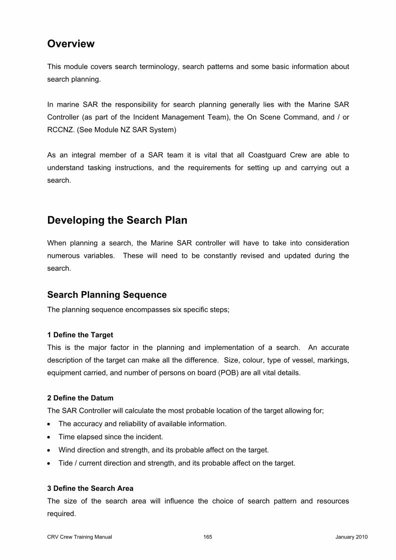
3 Define the Search Area The size of the search area will influence the choice of search pattern and resources
required.

CRV Crew Training Manual 166 January 2010
4 Select the Appropriate Search Pattern The selection of the appropriate pattern is often made after consultation with the On Scene
Command / CRV Skipper.
5 Determine the Desired Area Coverage The required coverage of the search area is dependant on the size of the search area,
resources available, and time available.
6 Develop a Practical Search Plan A practical search plan is a combination of the points above, and the conditions on scene.
The form shown below is an example showing the type of information that may be relevant to
the search operation. A record of the key information in any SAROP must be kept on
the CRV and updated when required.

CRV Crew Training Manual 167 January 2010
Search Terminology
Initial Position / Splash Point (IP / SP) The position where the distress incident first occurred.
Last Known Position (LKP) The last known position may not be the same as the initial position
Area of Probability (AOP) The area to be searched which is normally communicated to the CRV by reference to
charted objects / land features, or positions in Latitude & Longitude.
Datum (D) The probable location of the target (and hence start point of any search). This is not the
same as the Initial Position, as the target may have been subject to drift (due to tide / current
& wind) in the intervening time.
The Datum for a search may be;
• An individual position (Datum Point) in Lat & Long or distance and bearing from charted
object.
• It may be a line (Datum Line) representing the track of a missing vessel.
• Or it may be a given area (Datum Area) in which to commence the search.
In the diagram opposite the target gave a position
when it made the initial Distress call. (IP)
A subsequent position was given a little later, but
there has been no update since then. (LKP)
The Datum is the most likely position for the target given its estimated rate and direction of
travel (target drift) since the IP and LKP.
CRV Crew Training Manual 168 January 2010
Target Drift The direction and speed that a search target is estimated to be moving is known as Target
Drift. This is the combination of two main influences of the target;
• The wind and waves (leeway).
• The tide / current.
Any body of water can be subject to movement through tide or current. This can
include inland lakes where currents may be caused by a predominant wind, the
circulation of water due to differences in temperature, or rivers running into the lake.
There are tables available to the SAR Controller which give estimated leeway speeds for
different types of target, in different wind conditions. Combined with information on tidal
streams and current, this will produce an estimate on the targets drift.
The direction of a search should be orientated in the direction of the targets drift.
Depending on the rate of the targets leeway estimated by the SAR Controller, this can result
in a search pattern being orientated a varying angles to or even in the opposite direction to
the tide / current.
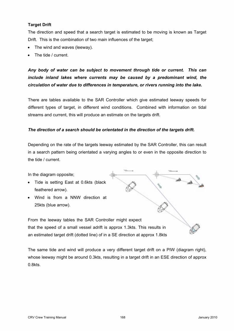
In the diagram opposite;
• Tide is setting East at 0.6kts (black
feathered arrow).
• Wind is from a NNW direction at
25kts (blue arrow).
From the leeway tables the SAR Controller might expect
that the speed of a small vessel adrift is approx 1.3kts. This results in
an estimated target drift (dotted line) of in a SE direction at approx 1.8kts
The same tide and wind will produce a very different target drift on a PIW (diagram right),
whose leeway might be around 0.3kts, resulting in a target drift in an ESE direction of approx
0.8kts.

CRV Crew Training Manual 169 January 2010
Any subsequent change in tide / current or wind direction & speed will have a corresponding
influence on the target drift.
In the diagrams opposite the wind speed, direction and
leeway remain the same as the previous diagrams, but the
tide has changed direction and weakened. This results in a
very different rate and direction of target drift.
This is why it is vital that the IMT – and more specifically
the SAR Controller, be kept in formed of any changes in
wind speed / direction and tide / current.
Leeway Angle / Divergence The job of the SAR Controller is further complicated by the fact that targets do not drift
directly downwind, but invariably move at an angle to the wind direction. This is known as
Leeway Angle or Divergence, and it has a profound effect on search planning.
Using one of the previous examples, the PIW
could be expected to move at an angle of up to
30° either side of the downwind direction. The
estimated leeway angles for different types of
targets are also contained within the leeway
tables used by the SAR Controller.
Maximum Detection Range The maximum distance each side of the vessel at
which the target might be located.
Maximum Detection Distance The sum of the maximum detection ranges each side of
the vessel.
Beam Sighting Distance (BSD) The BSD is distance that can be effectively searched
on either side of the vessel.

CRV Crew Training Manual 170 January 2010
The beam sighting distance should represent the maximum distance in which the
target will be, not could be detected.
Sweep Width (W) The sum of the distance effectively searched
each side of the vessel (beam sighting
distance x 2). Sweep width can apply to
multiple vessels - known as Total Sweep
Width.
Establishing the Sweep Width is crucial as
usually it forms the basis for setting up a
search pattern.
Track Spacing (S) The distance between successive search legs in a search pattern. Track spacing can also
apply to multiple vessels known as Total Track Spacing.
Search Leg Search legs are generally the longest tracks in a given search pattern.
Cross Leg Cross legs are the shorter tracks which connect the search legs

CRV Crew Training Manual 171 January 2010
Coverage (C) The Coverage Factor is a measurement of ‘quality’ or effectiveness of the coverage in a
search area. The coverage is determined by sweep width (W) and track spacing (T).
For example;
• If the sweep width is 1 NM but it is only possible to achieve a track spacing of 2 NM then
the coverage factor will be 0.5. (50%)
• If the sweep width is 1 NM and the track spacing is 0.5 NM then the coverage factor will
be 2. (200%)
In the first example the coverage is far from ideal, but time and resources available are
always factors in the SAR Controllers planning. It may be that coverage of 0.5 is the best
that can be achieved, at least on the initial search.
An example of this situation would be a search initiated only a short time before sunset. With
the resources available at the time it will not be possible to search the whole area with 100%
coverage before its dark. The SAR Controller may make the tactical decision to search the
AOP with a lower coverage, knowing that more resources will soon be available to search
the area again with a much higher coverage.
In such cases the track spacing may not be of
equal distance to the sweep width.
(Diagram right)
In the second example with coverage of 200% the
probability of detecting the target is far higher, but
consequently the time taken to search the AOP is
far greater.
In search operations;
Survivability decreases with the passage of time.
Search areas increase with the passage of time.
Sweep Width (W) Coverage Factor (C) =
Track Spacing (S)

CRV Crew Training Manual 172 January 2010
Probability of Detection (POD) In conversation it is normally referred to as POD (pee oh dee), and it is based on the
coverage of the search area achieved by single or multiple searches with different coverage
factors. SAR Controllers can calculate the POD of a search from tables and graphs available
to them. While not something that Coastguard crew are expected to calculate, it is a phrase
that is commonly used to describe the estimated effectiveness of a search.
Search Patterns
Shore Line Search A Shore Line search entails following the natural
contours of the land with due caution regarding any
hazards.
The distance off the land can often be maintained
using the Radars VRM (Variable Range Marker). The
search can be conducted with observers looking to
shore or on either side of the vessel.
Track Line Search A Track Line search follows the presumed track of a missing vessel. Conducted by one or
multiple vessels directly down the track, or offset by half the individual sweep width (beam
sighting distance)
The vessel(s) then returns along the other side of
the track using same offset. If the supposed track
of the missing vessel is entered as a route in the
CRV’s chart plotter, the correct off set can be
maintained by XTE (Cross Track Error) as well as
visually on the chart plotter.

CRV Crew Training Manual 173 January 2010
Barrier Search A barrier search is essentially a patrol between fixed points on the land, conducted by one or
multiple vessels. Principally used in rivers / estuaries or channels with significant tidal /
current flow. This would normally be conducted in conjunction with another vessel(s)
searching up tide / current of the Barrier Search.
Sector Search Used when the datum is well established and AOP is small. This pattern gives a very high
POD, and with pre calculated courses is easily executed.
The Sector Search is however limited in the area it
covers – once the length of the search legs exceed 3x
the sweep width, ‘gaps’ start to appear in the pattern.
Its coverage and hence POD is correspondingly
reduced.
The first leg is usually orientated in the probable
direction of the target drift, and the datum point itself is
marked with a floating datum.
The Sector Search can be carried out by two vessels; one vessel carries out the first sweep
while the second conducts the second sweep orientated 30° to starboard.
There must be a delay or separation between the vessels to avoid collision at or near
the datum point.

CRV Crew Training Manual 174 January 2010
Box or Square Search Used when the datum is reasonably well established and AOP is
relatively small. The Box Search does not give as high a POD as
a Sector Search, and is more complicated to carry out due to the
constant changes in distance and times for the search legs.
Unlike the Sector Search it is not limited in the area it can cover. The datum point itself can
be marked with a floating datum. The first leg is usually orientated in the probable direction
of the targets drift.
The Box Search can be carried out by two vessels (resulting in
a very high POD). The second vessel commences the same
pattern orientated 45° to Starboard. If the same speed is used
for both vessels, the first vessel must be allowed to complete at
least 3 search legs before the second commences to avoid risk
of collision.
Parallel Track & Creeping Line Parallel Track Used when the AOP is large and location of target not
well established. The search legs are parallel to the
major axis of the search area. The pattern can be
carried out by single or multiple vessels.
Creeping Line Used when the AOP is large and location of target is
more probable at one end of the search area. The
pattern can be carried out by single or multiple vessels.
Essentially the same as the Parallel Track but with the
search legs at right angles to the major axis of the
search area.
The Parallel Track and Creeping Line patterns are very
versatile and can be adapted to suit search areas of
various size and shape. They are probably the most
commonly used of all the search patterns.
CRV Crew Training Manual 175 January 2010
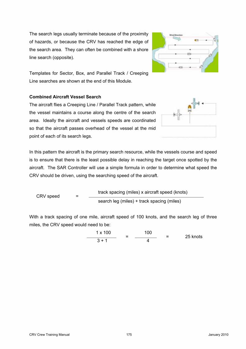
The search legs usually terminate because of the proximity
of hazards, or because the CRV has reached the edge of
the search area. They can often be combined with a shore
line search (opposite).
Templates for Sector, Box, and Parallel Track / Creeping
Line searches are shown at the end of this Module.
Combined Aircraft Vessel Search The aircraft flies a Creeping Line / Parallel Track pattern, while
the vessel maintains a course along the centre of the search
area. Ideally the aircraft and vessels speeds are coordinated
so that the aircraft passes overhead of the vessel at the mid
point of each of its search legs.
In this pattern the aircraft is the primary search resource, while the vessels course and speed
is to ensure that there is the least possible delay in reaching the target once spotted by the
aircraft. The SAR Controller will use a simple formula in order to determine what speed the
CRV should be driven, using the searching speed of the aircraft.
track spacing (miles) x aircraft speed (knots) CRV speed =
search leg (miles) + track spacing (miles)
With a track spacing of one mile, aircraft speed of 100 knots, and the search leg of three
miles, the CRV speed would need to be:
1 x 100 100
3 + 1 =
4 = 25 knots

CRV Crew Training Manual 176 January 2010
Use of GPS
Important - When searching an area for a target on the water (not anchored or aground)
such as in a Box, Sector, or Creeping line pattern, searches are run using;
• The compass for direction.
• Time at a set speed, to determine the length of search legs or cross legs as required.
This is to maintain the search patterns sweep width, and track spacing on the surface of the
water, regardless of tide / current. While the search area may be defined by fixed
geographical points such as charted objects on land, or a position in Lat & Long, the CRV
must carry out a search of the water surface within that area.
The influence of tide or current can have a marked effect on a search pattern when it is
viewed on a chart plotter. The GPS chart plotter shows positions, and hence course and
speed over the ground (sea / lake bed).
A search pattern accurately steered through the water can appear distorted on a chart
plotter. The diagram below left shows the track of a vessel through the water (black), and
what it would look like on a chart plotter (red) with the tide / current running in a South
Easterly direction.
With the tide / current running in the opposite direction (below right), the track shown on the
chart plotter now looks quite different.
The diagrams above are drawn in correct proportions for a tide / current speed of
approx 1/8 of the vessels speed through the water. I.e. Vessels speed through the
water 8kts, tide / current speed 1.0kts
CRV Crew Training Manual 177 January 2010
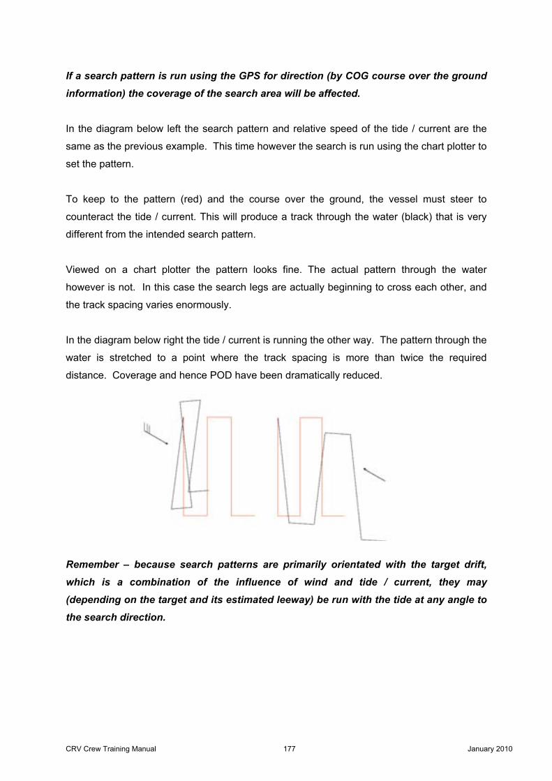
If a search pattern is run using the GPS for direction (by COG course over the ground
information) the coverage of the search area will be affected.
In the diagram below left the search pattern and relative speed of the tide / current are the
same as the previous example. This time however the search is run using the chart plotter to
set the pattern.
To keep to the pattern (red) and the course over the ground, the vessel must steer to
counteract the tide / current. This will produce a track through the water (black) that is very
different from the intended search pattern.
Viewed on a chart plotter the pattern looks fine. The actual pattern through the water
however is not. In this case the search legs are actually beginning to cross each other, and
the track spacing varies enormously.
In the diagram below right the tide / current is running the other way. The pattern through the
water is stretched to a point where the track spacing is more than twice the required
distance. Coverage and hence POD have been dramatically reduced.
Remember – because search patterns are primarily orientated with the target drift,
which is a combination of the influence of wind and tide / current, they may
(depending on the target and its estimated leeway) be run with the tide at any angle to
the search direction.

CRV Crew Training Manual 178 January 2010
Outlining the AOP While GPS is not generally used to run area search patterns, it can be used to outline the
AOP. This can be especially useful in a Parallel Track / Creeping Line Search. In a Sector
or Box Search every leg needs to be timed, but if the AOP is outlined in a Parallel Track /
Creeping Line Search then only the cross legs need be timed.
• Some chart plotters will allow the operator to draw lines / bearings on the screen – which
can be used to draw the outline of the search area.
• Alternatively with the corners of the search area entered as waypoints they can be joined
as a ‘route’.
• A Chart plotter can be used to display the edge of the AOP regardless of ‘zoom’.
The vessel should ideally turn to initiate a cross leg when it is half the track spacing from the
edge of the search area. To identify the turning point;
• Most chart plotters will give distance and bearing to the cursor, so if the cursor is placed
on the edge of the search area, this can be used to indicate the turning point.
• With the option of Radar overlay a VRM can be set to show the distance to the edge of
the search area.

CRV Crew Training Manual 179 January 2010
Use of Floating Datum
A floating datum is a marker that is deployed in the water. It should be;
• Highly visible (brightly coloured / reflective tape / flag attached).
• Have a light / strobe attached for use at night.
• Be able to be deployed quickly.
• Be affected as little as possible by the wind - to ensure it drifts at the same
rate and direction as the surrounding body of water.
Marking the Search Datum A floating datum can be deployed at the start of such patterns as the Sector or Box search.
• The time at the start of the search is recorded.
• A waypoint is entered on the GPS.
• If the target is not found in the initial search, the floating datum is recovered.
• The distance to the waypoint and the time between deploying and recovering the floating
datum will give a fairly accurate rate and direction for tide / current in the area.
With a Sector search the floating datum also provides a reference point so that small
corrections to the CRV’s course can be made to maintain the pattern.
Pausing or Leaving a Search Pattern If a search is temporarily suspended for any reason (taking a break to rotate / rest crew or
leaving the pattern to investigate a possible sighting);
• The time is recorded.
• A waypoint is entered on the GPS.
• The IMT is informed.
• A floating datum is deployed.
A GPS position/waypoint can be used to return to the general area, but the floating datum
will help the CRV return to the actual point in the water to recommence the search.
The smaller the sweep width / track spacing, and the stronger the tide / current then
the more important the use of a floating datum becomes.
CRV Crew Training Manual 180 January 2010
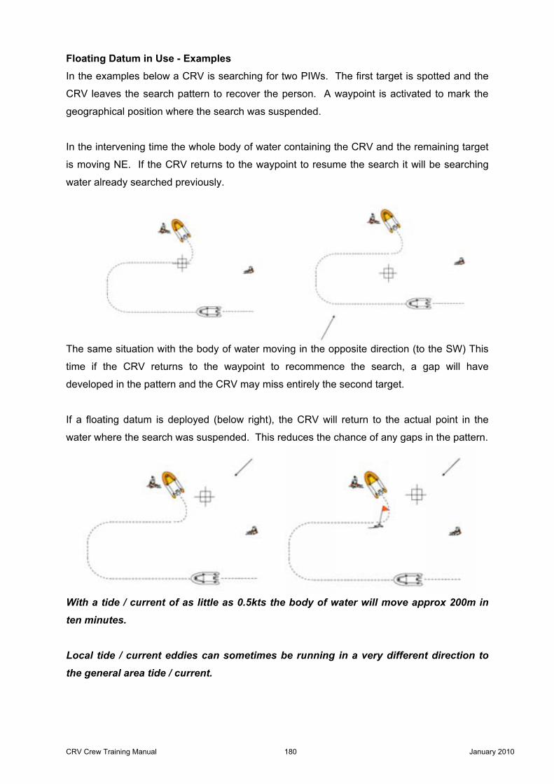
Floating Datum in Use - Examples In the examples below a CRV is searching for two PIWs. The first target is spotted and the
CRV leaves the search pattern to recover the person. A waypoint is activated to mark the
geographical position where the search was suspended.
In the intervening time the whole body of water containing the CRV and the remaining target
is moving NE. If the CRV returns to the waypoint to resume the search it will be searching
water already searched previously.
The same situation with the body of water moving in the opposite direction (to the SW) This
time if the CRV returns to the waypoint to recommence the search, a gap will have
developed in the pattern and the CRV may miss entirely the second target.
If a floating datum is deployed (below right), the CRV will return to the actual point in the
water where the search was suspended. This reduces the chance of any gaps in the pattern.
With a tide / current of as little as 0.5kts the body of water will move approx 200m in
ten minutes.
Local tide / current eddies can sometimes be running in a very different direction to
the general area tide / current.

CRV Crew Training Manual 181 January 2010
Establishing Sweep Width
The ability to establish a viable sweep width is crucial. Every opportunity should be taken to
practice establishing realistic sighting distances (by both visual & Radar observation) for a
variety of objects, and in different conditions.
The SAR Controller may have a theoretical sweep width in mind for a search pattern,
but it is only the CRV crew that can provide an actual sweep width for the prevailing
conditions.
• Using Radar to verify an objects distance is a useful practice (which also gets crew
familiar with some of the basic Radar functions).
• Alternatively an estimate on the objects distance can be made, a waypoint activated and
the CRV driven to the object (such as a mooring buoy). The GPS will give a reasonably
accurate distance travelled by the range to the waypoint (also gets crew familiar with
basic GPS / chart plotter functions).
• Another practice is for the CRV to drive away from the object (typically a small object
such as a mooring buoy or something similar deployed from the CRV). The time is
recorded for the object to be still visible for approx 50% of the time, which will be the
effective sweep width. The comparison of time / speed will give the distance from the
object (also gets crew familiar with time / speed / distance tables).
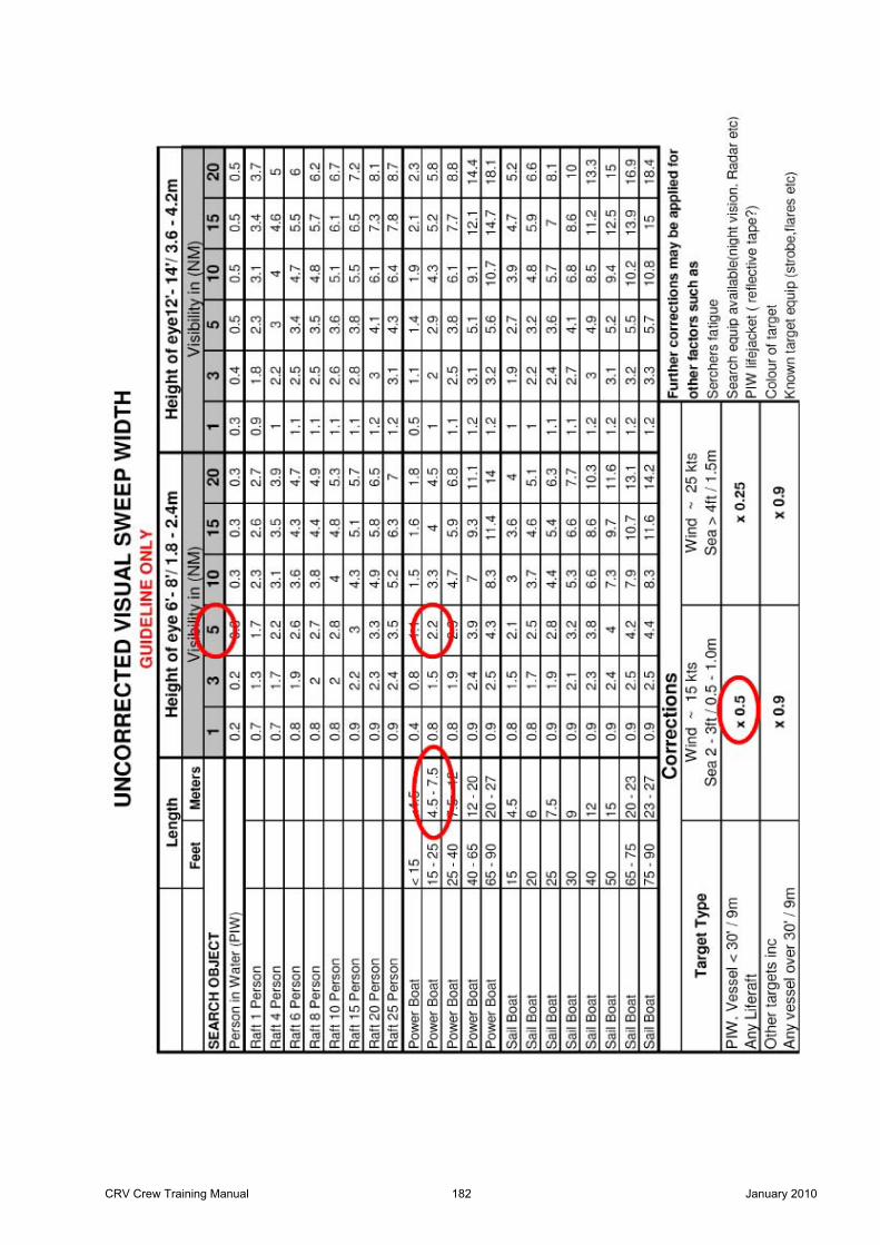
On the next page is an example table of Visual Sweep Width Guidelines. The main body of
the table is of uncorrected sweep widths (calm sea, no wind or swell). Below the main body
are correction factors that can be applied depending on the wind strength and sea state. For
example;
• Visibility approx 5NM (Fair)
• Target 6m power boat.
• Uncorrected Sweep Width of 2.2NM.
• With wind and sea state correction of x 0.5 applied.
• Corrected Sweep Width is 1.1NM.
The tables do not factor in swell, which can have a huge effect on sweep width.
These are just guidelines – an aid that will help in establishing ‘ball park’ figures. Only
practice and experience will enable you to improve these figures.
CRV Crew Training Manual 182 January 2010
CRV Crew Training Manual 183 January 2010
Time / Speed / Distance
Speed & Distance Tables Once a viable sweep width has been established, the next decision is usually what speed? It
should be the fastest speed at which observation is still effective. If the CRV’s motion
means crew have to constantly struggle to hold on, they are unlikely to be very effective
observers. Alternatively the search could be conducted at a very slow comfortable speed,
but in search operations;
Survivability decreases with the passage of time.
Search areas increase with the passage of time.
Using the tables the time for the distance and speed can be established.
As mentioned previously Creeping Line / Parallel Track patterns usually need only the cross
legs to be timed.
With Sector or Box searches every leg needs to be timed. The legs can be timed singly; with
the stopwatch stopped, reset and started again each time. This can lead to problems with
the delay, and with the increased chance of mistakes.
Alternatively the legs can be timed consecutively, with the cumulative time used to mark the
end of each leg. This method also has its drawbacks, as calculating / setting up can be time
consuming and prone to error. Having an ‘easy’ time to work with can make all the
difference.
To help with this certain time values have been highlighted in the tables i.e. values above 10
seconds with 5, 10, 15, 20 & 30 seconds as part of the value. Any times + /- 2 seconds of
these values have also been highlighted, to indicate times that could easily be rounded up or
down to obtain a better time to work with.

CRV Crew Training Manual 184 January 2010
Using the extract from the tables below;
A distance of 100m at 10 kts gives a time of 19 seconds. This could be rounded up to 20
seconds without any significant change to the effectiveness of the search pattern, but it will
be a whole lot easier to use.
With 20 sec as the chosen time a Sector search could be conducted with all legs timed at 1
min. A Box search would have the first 2 legs at 20sec, the next two at 40sec, and the next
two at 1 min and so on.
To get a feel for how much an adjustment to speed or time actually means, it is useful
to remember that to convert kts to meters / second you multiply by 0.5 (half the value)
I.e. at 10kts the CRV covers approx 5m / sec.
So if you round up a given time by a second you will be increasing the distance travelled in
meters by approx half the speed of the vessel. Round a time up by 2 secs and you will have
increased the distance in meters by the speed of the vessel.
For example;
At 10kts in 19 secs you will cover approx 100m
At 10kts in 20 secs you will cover approx 105m (+ 5m – half the boat speed)
At 10kts in 21 secs you will cover approx 110m (+10m – the boat speed)
CRV Crew Training Manual 185 January 2010
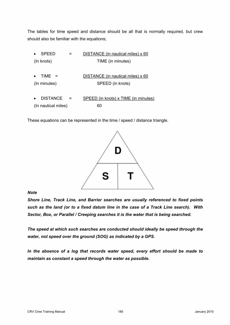
The tables for time speed and distance should be all that is normally required, but crew
should also be familiar with the equations;
• SPEED = DISTANCE (in nautical miles) x 60
(In knots) TIME (in minutes)
• TIME = DISTANCE (in nautical miles) x 60
(In minutes) SPEED (in knots)
• DISTANCE = SPEED (in knots) x TIME (in minutes) (In nautical miles) 60
These equations can be represented in the time / speed / distance triangle.
Note
Shore Line, Track Line, and Barrier searches are usually referenced to fixed points
such as the land (or to a fixed datum line in the case of a Track Line search). With
Sector, Box, or Parallel / Creeping searches it is the water that is being searched.
The speed at which such searches are conducted should ideally be speed through the
water, not speed over the ground (SOG) as indicated by a GPS.
In the absence of a log that records water speed, every effort should be made to
maintain as constant a speed through the water as possible.

CRV Crew Training Manual 186 January 2010
Search Pattern Templates
Sector The Sector search template contains pre calculated courses based on the initial course being
one of the cardinal points of the compass i.e. North, South, East or West.
Alongside each of the courses is a box for the individual legs if cumulative time is used. It is
advisable to cross out or tick each leg once it has been completed.

CRV Crew Training Manual 187 January 2010
Box / Square The square search templates contain pre calculated courses. These are based on the initial
course being one of the cardinal or inter cardinal points of the compass i.e. North, Northeast,
East, and Southeast etc.
CRV Crew Training Manual 188 January 2010
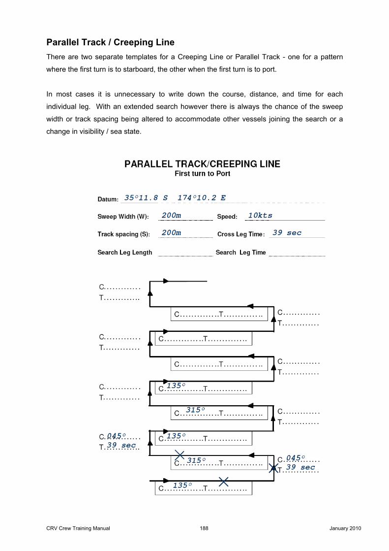
Parallel Track / Creeping Line There are two separate templates for a Creeping Line or Parallel Track - one for a pattern
where the first turn is to starboard, the other when the first turn is to port.
In most cases it is unnecessary to write down the course, distance, and time for each
individual leg. With an extended search however there is always the chance of the sweep
width or track spacing being altered to accommodate other vessels joining the search or a
change in visibility / sea state.