Week 9 - Nov 7, 2005 1 Week 9 Agenda I/O redirection I/O redirection pipe pipe tee tee.
date post
21-Oct-2014Category
view
523download
2description

9 Pipe Structures Pipe Types Pipe End Treatments Pipe End Section Grated Box End Section Structure Order Pipe Order Cross-Section View Computing Structure Length Using Elbows Structure Field Layout Staking Structures Normal Layout Laser Layout Checking Grade Batterboard Laser Grade Control Basis for Use for Pipe Materials Metal Pipe Concrete Pipe Plastic Pipe Metal Pipe End Safety Metal End Section Other Items Recording Tags for Basis of Use Multi-Plate Pipe Miscellaneous Concrete Recording Tags for Future Use

9-1
CHAPTER NINE: PIPE STRUCTURES
Proper placement and backfilling of pipe structures is critical for maintaining the base support for the pavement placed over the pipe, and for providing correct loading of the pipe for structural integrity. In this chapter the installation methods for pipe and sewer work will be discussed.
PIPE TYPES
Pipe is specified by types, according to the pipe use, as set out in the miscellaneous Standard Sheets. Type 1 is placed under mainline or public road approaches, Type 2 is used for storm sewers, Type 3 is placed under all drives and field entrances, and Type 4 is used for drainage tile and longitudinal underdrains. Under each pipe type, the pipe materials that are required are indicated. These sheets also indicate the pipe material abbreviations which are used throughout construction in the plans and proposals (Figure 9-1). When pipe is listed by type, the Contractor may use any pipe material that meets the requirements of that type. If the item states a pipe material such as Reinforced Concrete Pipe, that is the material that is required to be used. When using the Standard Drawings, the Standard Drawing index in the proposal is checked for the effective date of the standards required for the contract. The effective date on the standard sheet is required to be prior to the contract letting date for that standard to apply to the contract. On the plans, this date appears on the same sheet as the general notes. In a proposal, the date is listed in the Standard Drawing Index.
Figure 9-1. Standard Drawing
9-2
Besides listing pipe materials, the Standard Drawings list notes for cover limits and other installation information. Standard Drawing E 715-PIPE-01 is checked for the pipe type listing table.
PIPE END TREATMENTS
There are several different types of pipe end treatments being used. The Technician is required to know which type is required for each structure because some end treatments affect the length of pipe necessary for construction. The standard drawings indicate details for each type of end treatment. The end treatments used are as follows:
1) Metal pipe end sections
2) Safety metal sections
3) Concrete pipe anchors
4) Grated box end sections
5) Inlets or Catchbasins
6) Manholes
Of the units indicated above only concrete pipe anchors do not affect the overall length of a pipe structure significantly. The following drawings indicate how different pipe end treatments affect the pipe length.
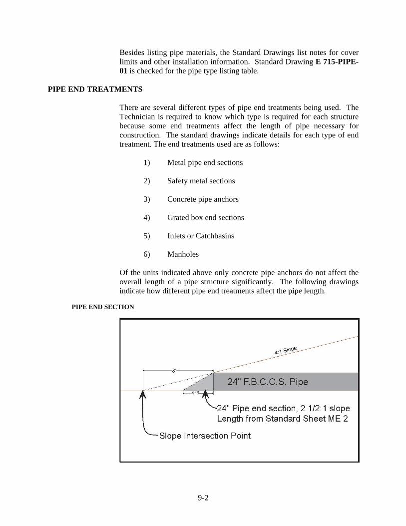
PIPE END SECTION

9-3
In the above layout, the end section of the pipe is controlled by the intersection with the foreslope.
GRATED BOX END SECTION
If a grated box end section (GBES) was being used on the same type of slopes, there would be 6 ft less pipe on each end of the pipe structure.
STRUCTURE ORDER
PIPE ORDER
The pipe order is required to include the pipe types, sizes, and lengths. The PE/PS is responsible for reviewing all of the structures thoroughly before ordering. This review may involve site surveys to verify the pipe lengths are correct, and to check for possible problems in the pipe size. In new construction, most structure lengths may be computed using cross sections and the proposed flowline elevations. Special notes, such as locations for Tees or Elbows, are shown. There is no special form for a pipe structure order. The order may be written as shown in the following example:
9-4
The remarks column is used for special notes for a certain structure.
Structure lengths are affected by the following:
1) Pavement width
2) Slope
3) Horizontal skew
4) Vertical skew
5) Type of end treatment
Following are two examples of how structure lengths may be affected. When calculating the length of required pipe, the final value is required to be rounded up. Assume that metal pipe end sections are being used.
CROSS-SECTION VIEW
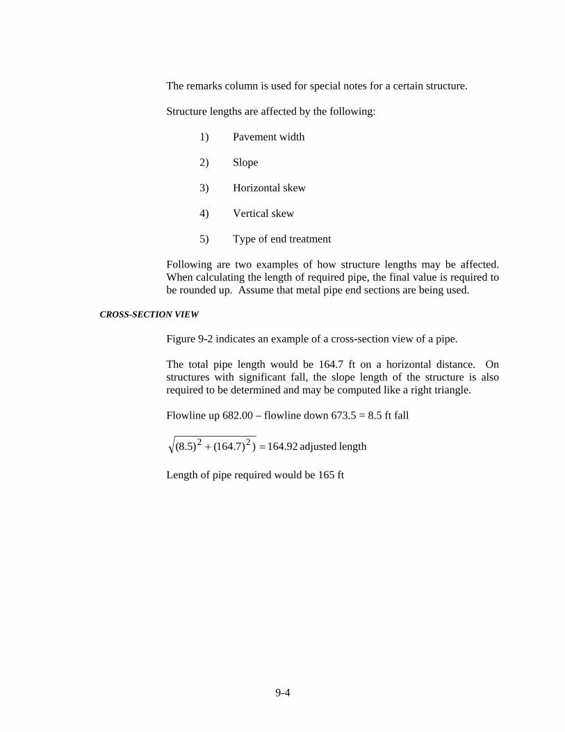
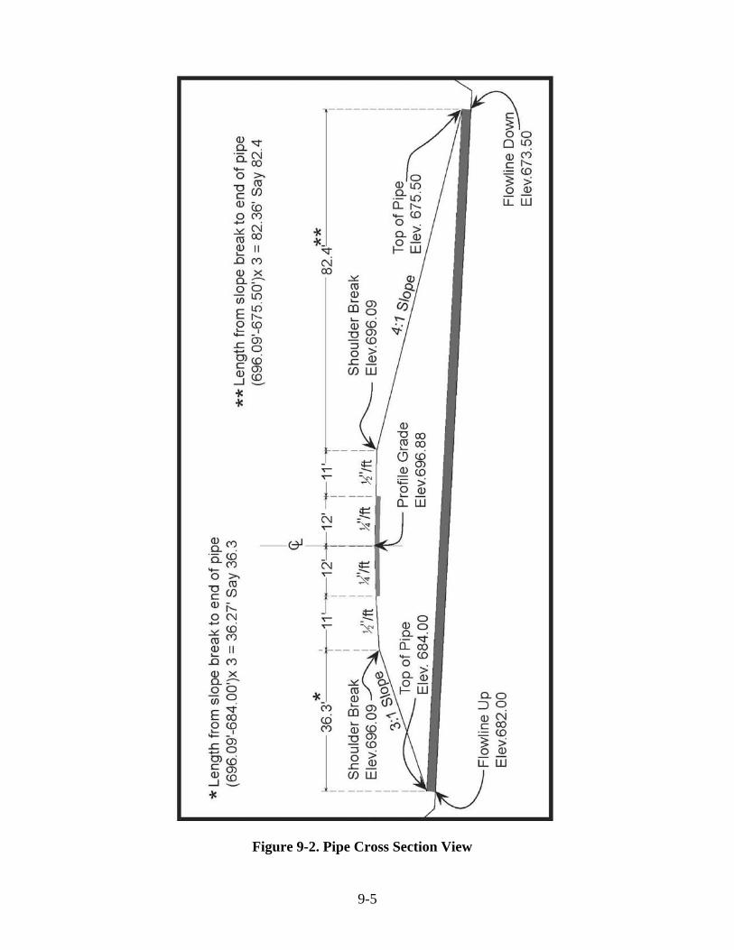
Figure 9-2 indicates an example of a cross-section view of a pipe.
The total pipe length would be 164.7 ft on a horizontal distance. On structures with significant fall, the slope length of the structure is also required to be determined and may be computed like a right triangle.
Flowline up 682.00 – flowline down 673.5 = 8.5 ft fall
length adjusted 164.92))7.164()5.8( 22 =+ Length of pipe required would be 165 ft
9-5
Figure 9-2. Pipe Cross Section View

9-6
Sometimes structures are placed on a skew rather than right angles to centerline. This placement adds another adjustment to the structure length computations. Using the typical section in Figure 9-2, the affect of a skew on the structure is indicated below.
The length of pipe may be computed using trigonometric functions. In this example, the length is C / Cosine of the skew angle:
1) 59.3 ft / Cosine 30° = 68.47 ft (Say 68.5 ft) 2) 105.4 ft / Cosine 30° = 121.7 ft (Say 121.7 ft)
Skew length = 190.2 ft
3) Adjustment for flowline fall:
ft) 190.4(Say ft 190.39))2.190()5.8(( 22 =+ Order length would be 190 ft

9-7
COMPUTING STRUCTURE LENGTH USING ELBOWS
Sometimes structures use elbows or bends to decrease the depth of cut in large fills. The following example (Figure 9-3) displays the proper method for computing pipe lengths when bends or elbows are used.
E-7 Inlet inside measure = 2.5 ft/ 2 = 1.25 ft on CL to end of pipe If elbows = 4 ft measured along CL: Section (1) = 75 ft – Inlet offset (1.25 ft) – Elbow = 75 – 1.25 – (4/2) = 71.75 (Say 72 ft) Section (2) = FL up 696.29 – FL Down 677.96 = 18.33 ft
ft 57.97)55)((18.33)Length 22 =+=
57.97 ft – (8/2 ft for 2 elbows) = 53.97 ft (Say 54 ft) Section (3) = 15 ft – 2 ft for elbow + (680.08 – 676.29)3
= 24.37 (Say 24 ft) Totals Section (1) 72 ft (2) 54 ft (3) 24 ft _______________________________
150 ft plus 2 elbows & 1 pipe end treatment

9-8
Figure 9-3. Structure With Bend or Elbow

9-9
The pipe order indicates the layout on a structure like Figure 9-3 rather than just the total pipe required. Otherwise, the pipe manufacturer would not break down the total length into pieces suitable for the planned assembly.
STRUCTURAL FIELD LAYOUT
STAKING STRUCTURES
Each structure is required to have a layout drawing showing the structure and the stake locations. The Contractor is required to indicate what method of grade control is planned. Laser grade control on long pipe or sewer runs is currently being used by some Contractors.
NORMAL LAYOUT
On normal staking layouts, the stakes are set on an offset line parallel to the pipe and spaced approximately every 25 ft, at an alignment change, or at a grade break. Stakes are set at a specified distance from the centerline of the pipe structure so that the centerline may be re-established as needed. Also, stakes are set where they are least likely to be disturbed. How the Contractor plans to place the structure is discussed before the layout begins. All Contractors work differently and sometimes one side of the structure may be preferred for placing the stakes.
After staking a structure, the layout is discussed with the Contractor and a copy of the layout provided. All stakes are labeled clearly so the layout may be easily followed. Stakes are marked for line only or line and grade offset. The position of the pipe relative to the survey centerline is clearly indicated.
LASER LAYOUT
When the Contractor uses laser grade control, the Technician is required to know the flowline fall expressed in "percent of fall". This value is computed by the formula:
FL Elev. Upstream – FL Elev. Downstream x 100% Horizontal Length of Pipe

9-10
CHECKING GRADE
The different methods of checking the grade from structure stakes include the following:
1) Level rod readings taken from structure stakes to
excavation trench
2) Batterboard and stringline
3) Laser grade control
Batterboard and Stringline
The batterboard and stringline method uses a post and a crossarm mounted a predetermined height above each grade stake. The crossarm is required to be level and have a stringline on either end. The stringlines are stretched from one batterboard to the next, and the grade is checked by sighting across the stringlines to the level rod.
Example:
To set a batterboard for a constant 8 ft cut Cut from grade stake #1 = 6.18
Measure up = 1.82 Reading to FL 8.00
Cut from grade stake #2 = 5.13
Measure up = 2.87 Reading to FL 8.00

9-11
LASER GRADE CONTROL
When using laser grade control, a known elevation point is first established, relative to the structure flowline. The laser is then set up a specified distance above that point and the percent of fall dialed in. To check the grade anywhere along the flowline, the predetermined distance is measured down from the laser beam.
BASIS OF USE FOR PIPE MATERIALS
Different types of pipe materials have different testing markings.
METAL PIPE
Metal pipe items are marked with metal tags having a 6 digit number stamped onto the tag. This tag verifies that the pipe has been inspected.
CONCRETE PIPE
Concrete pipe items are required to be produced by a Certified Precast Concrete Producer on the Approved list. The pipe is required to have the date of manufacture and the source number on the pipe. Also, pipe manufactured by a Producer who is also certified by the American Concrete Pipe Association is required to have the "QCast "symbol or have the words "ACPA Certified Material" on the pipe. Pipe manufactured by a manufacturer also certified by the National Precast Concrete Association is required to have the words "NPCA Certified Material" on the pipe.
PLASTIC PIPE
Plastic pipe items are accepted by a Certification stating that the pipe meets the required Specification ratings. This certification is usually a Type A or Type C as indicated in the Frequency Manual.

9-12
METAL PIPE END
Metal pipe end sections have tag numbers as described for metal pipe.
SAFETY METAL END SECTION
Safety metal end sections have tag numbers as described for metal pipe.
OTHER ITEMS
Precast inlets, catchbasins, manholes, and GBES are required to be produced by Producers that are on the Approved list for Certified Precast Concrete Producers the same as concrete pipe.
RECORDING TAGS FOR BASIS OF USE
When a shipment of metal pipe arrives on the job-site, all tag numbers on the invoice are recorded as the pipe is checked. The count of these numbers and units is required to agree with what the Supplier is indicating. The PE/PS also receives a report (TD-392) from the pipe plant Technician indicating all the pipes produced and the corresponding tag numbers.
MULTI-PLATE PIPE
On structural plate steel pipe or multi-plate pipe, a yellow card is attached to the invoice indicating the inspection numbers. A pipe report is issued by the pipe Technician, similar to the report for the other pipe items.
MISCELLANEOUS CONCRETE
For any concrete items poured in place, such as pipe anchors, inlets, or pipe collars, the basis of use is the report number from the IT 652.
RECORDING TAGS FOR FUTURE USE
When placing pipe items, the pipe tag numbers are recorded in the Technician’s daily reports and in the structure book. These numbers are used by the PE/PS to obtain lab numbers necessary for the completion of the material record.