9 30 Checker Building Structural analysis and design ZYChen...
16
17/11/2014 1 Checker Building – Structural Analysis and Design Zhiyong Chen 1 , Minghao Li 2 , Ying H. Chui 1 , Marjan Popovski 3 , Eric Karsh 4 , and Mahmoud Rezai 4 1 Univ. of New Brunswick, 2 Univ. Canterbury, 3 FPInnovations, and 4 Equilibrium Consulting Inc. www.NEWBuildSCanada.ca 67.310 50.000 40.000 30.000 20.000 ±0.000 10.000 67.31m Yingxian Wood Pagoda Wood as a structural material can date back to more than 7000 years. Stadthaus 1. Background … ? f/ρ, materials & technology 32.25m Horyu-ji Temple >30m 2
Transcript of 9 30 Checker Building Structural analysis and design ZYChen...
17/11/2014
1
Checker Building – Structural Analysis and Design
Zhiyong Chen1, Minghao Li2, Ying H. Chui1, Marjan Popovski3, Eric Karsh4, and Mahmoud Rezai4
1 Univ. of New Brunswick, 2 Univ. Canterbury,3 FPInnovations, and 4 Equilibrium Consulting Inc.
www.NEWBuildSCanada.ca
65.880
50.000
40.000
30.000
20.000
10.000
0.000
67.310
50.000
40.000
30.000
20.000
±0.000
10.000
67.31m
Yingxian Wood Pagoda
Wood as a structural material can date back to more than
7000 years.
Stadthaus
1. Background
…?f/ρ,
materials &technology
32.25m
Horyu-ji Temple
>30
m
2

17/11/2014
2
20-Storey Mass Timber Building – CHECKER
3
Design data North Vancouver: “high earthquake, wind
and rain”
20 storeys: 19 standard storeys + 1 podium
Total height: about 60m with 3m per storey
Plan dimensions: 27m x 27m with 9m grid
Wood Materials: structural composite lumber
(SCL), cross laminated timber (CLT), and
glued laminated timber (Glulam)
Connection: Wood-Steel-composite (HSK)
system, Wood-Concrete-composite (HBV)
system, and dowel-type connection
20-storey timber building
2. Structural Challenges & Solutions No. 1 – high wind and seismic load develop a shearwall + core system of high stiffness, strength, and ductility
4
Simplified
Lateral load resisting system Schematic diagram of the LLRS
17/11/2014
3
2. Structural Challenges & Solutions No. 1 – high lateral wind and seismic load establish a high performance connection system
5Dowel type connection with self-tapping screws for panel-to-panel
HSK system for use as hold-down and shear connections for panel-to-panel and to the concrete podium
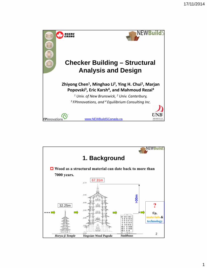
2. Structural Challenges & Solutions No. 2 – large vertical deformation & complicated horizontal
connections balloon framing construction technique
6Gravity load resisting system

17/11/2014
4
2. Structural Challenges & Solutions No. 3 – long span floor & roof wood-concrete composite system
7
Glulam-concrete composite floor
2. Structural Challenges & Solutions No. 4 – No design principles
8
Size Structural Assemblies & Connections
Design Criteria
Code Provisions
Final Design
Mechanical Theory
Numerical Simulation
[No]
[Yes]
17/11/2014
5
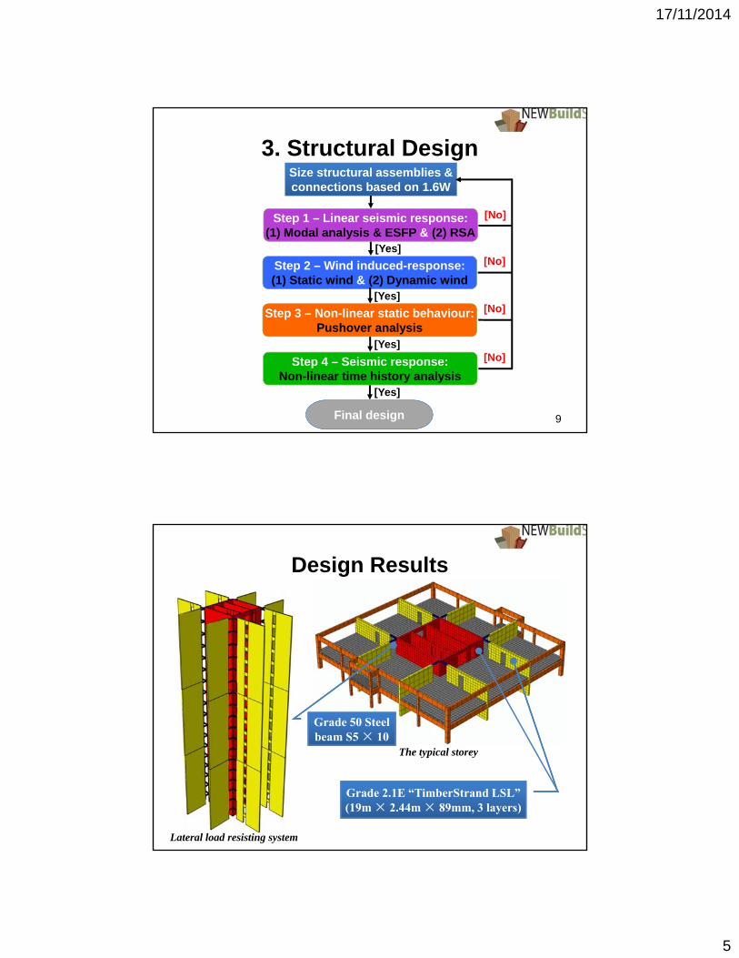
Step 2 – Wind induced-response:(1) Static wind & (2) Dynamic wind
Size structural assemblies & connections based on 1.6W
3. Structural Design
[Yes]
[No]
[Yes]
[Yes]
[Yes]
[No]
[No]
[No]
9
Step 1 – Linear seismic response:(1) Modal analysis & ESFP & (2) RSA
Step 3 – Non-linear static behaviour:Pushover analysis
Step 4 – Seismic response:Non-linear time history analysis
Final design
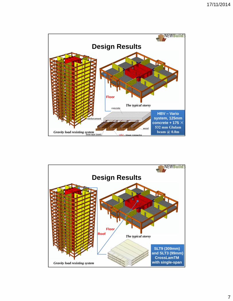
Design Results
Lateral load resisting system
Grade 50 Steel beam S5 × 10
Grade 2.1E “TimberStrand LSL” (19m × 2.44m × 89mm, 3 layers)
The typical storey

17/11/2014
6
Design Results
Dowel-type connection (19mm) of LSL with k=25.5kN/mm & Pmax=32.5kN
HSK system, Pmax=0.8kN, Kparallel=7.4kN/mm & Kperpendicular=2.5kN/mm for each hole
Lateral load resisting system
The typical storey
Design Results
DLF 24f-E Glulam beam(315×532mm)
DLF 16c-E Glulam column(365×418mm & 730×418mm)
Gravity load resisting system
The typical storey
17/11/2014
7
Design Results
Floor
HBV – Vario system, 125mm
concrete + 175 ×532 mm Glulam
beam @ 0.8mGravity load resisting system
The typical storey
Design Results
Roof
SLT9 (309mm) and SLT3 (99mm)
CrossLamTMwith single-span
Floor
Gravity load resisting system
The typical storey

17/11/2014
8
4. Numerical Simulating Solutions
15
Strong assembly - weak connectionMacro-element model for connections
Deformation
Force
Deformation
Force
Macro-element connectors
(a) Vertical & shear connectors
(b) Hold-down connector
FEM of CHECKER
Macro-element model for connector
A
B
5.1 Gravity loading – differential shortening
5. Modeling Structural Performance
(a) In X (E-W) direction (b) In Y (N-S) direction
The differential shortening is not significant. 16
17/11/2014
9
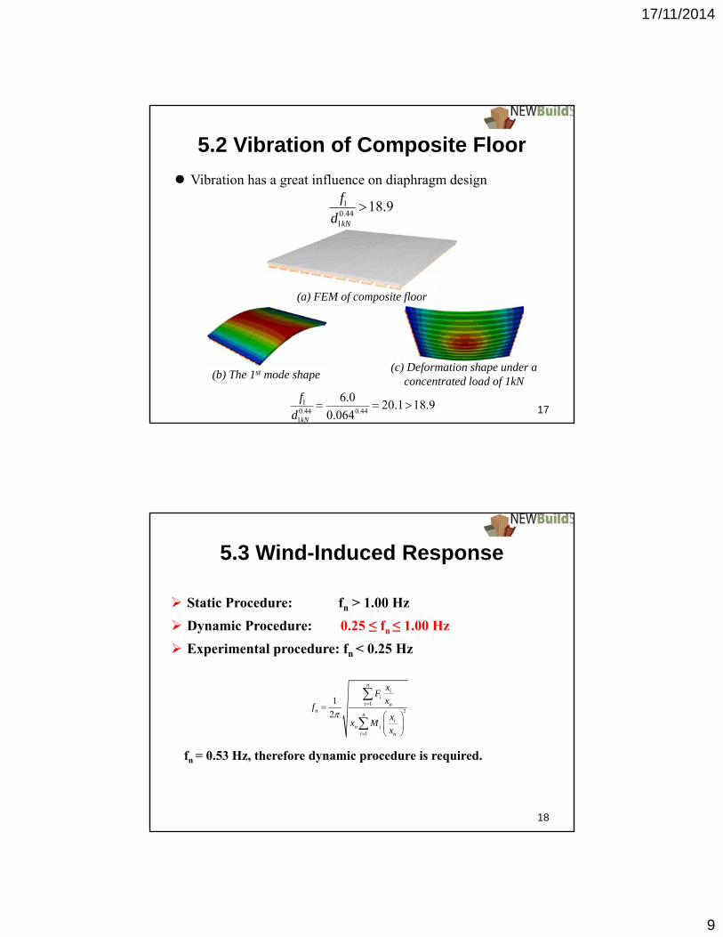
5.2 Vibration of Composite Floor
Vibration has a great influence on diaphragm design
17f1
d1kN0.44
6.0
0.0640.44 20.118.9
(a) FEM of composite floor
(b) The 1st mode shape(c) Deformation shape under a
concentrated load of 1kN
f1d1kN
0.4418.9
Static Procedure: fn > 1.00 Hz
Dynamic Procedure: 0.25 ≤ fn ≤ 1.00 Hz
Experimental procedure: fn < 0.25 Hz
fn = 0.53 Hz, therefore dynamic procedure is required.
12
1
1
2
ni
ii n
nn
in i
i n
xF
xf
xx M
x
18
5.3 Wind-Induced Response

17/11/2014
10
5.3 Wind-Induced Response FEA was performed to calculate the lateral deformation of the
tall wood building under wind load.
iP
19
5.3 Wind-Induced Response
0 10 20 30 400
5
10
15
20
Num
ber
of S
tore
y
Lateral Drift, mm
Static Dynamic
0.0 0.5 1.0 1.5 2.0 2.50
5
10
15
20
Num
ber
of S
tore
y
Inter-Storey Drift, mm
Static Dynamic
(a) Storey drifts (b) Inter-storey drifts
Under static wind load: the roof drift is 31.2 mm (≈hn/1800) and the inter-storey drift of each storey is less than hi/500 (=6mm).
Under pseudo-static wind load: the roof drift is 33.7 mm (≈hn/1700) and the inter-storey drift of each storey is less than hi/500 (=6mm).
20

17/11/2014
11
5.3 Wind-Induced Response
The across- and along-wind accelerations, aW and aD (m/s2), were estimated by
Substituting the values of the parameters into equations, aW
and aD are 0.9% and 1.1% of g, which are both less than the acceleration limits of 1.5%g for residential occupancy.
2 rW nW p
B W
aa f g wd
g
2 24 SD nD p
eH D g
K Fa f g
C C
21
5.4 Seismic Response(1) Fundamental Natural Period, Ta
the period of the FEM of the building was 1.97 s. It is almost twice that estimated by NBCC equation.
(2) Seismic Force Modification Factor, Rd
CLT Handbook: Ro=1.5 and Rd=2.0 for CLT panel system
The tall wood report: a higher Rd value (3.5) could be used
Pushover analysis: Rd= 2.03
Therefore RoRd = 3.0 (1.5 × 2.0) was used.
(3) Design lateral earthquake force, V, (Equivalent Static Force Procedure)
the specified design base shear is about 4893kN.
3 40.05 1.04a nT h s
22
a V E d oV S T M I W R R
17/11/2014
12
0 5 10 15 20 25 300
5
10
15
20
Num
ber
of S
tore
y
Inter-Storey Drift, mm
xi
xiR
dR
o/I
E
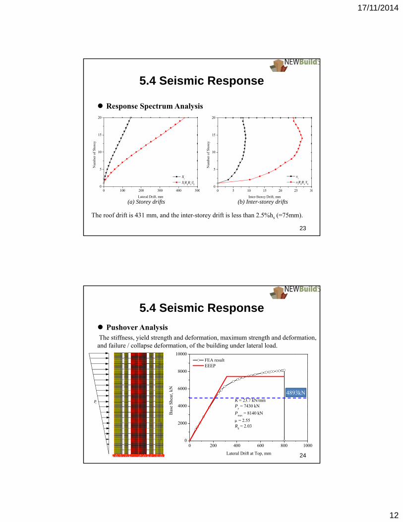
5.4 Seismic Response
Response Spectrum Analysis
(a) Storey drifts (b) Inter-storey drifts
The roof drift is 431 mm, and the inter-storey drift is less than 2.5%hs (=75mm).
23
0 100 200 300 400 5000
5
10
15
20
Num
ber
of S
tore
y
Lateral Drift, mm
Xi
XiR
dR
o/I
E
5.4 Seismic Response
Pushover AnalysisThe stiffness, yield strength and deformation, maximum strength and deformation,
and failure / collapse deformation, of the building under lateral load.
iP
24
0 200 400 600 800 10000
2000
4000
6000
8000
10000
K = 23.7 kN/mmP
y = 7430 kN
Pmax
= 8140 kN
= 2.55R
d = 2.03
FEA result EEEP
Bas
e S
hear
, kN
Lateral Drift at Top, mm
4893kN

17/11/2014
13
5.4 Seismic Response
Pushover Analysis
(a) Yield of vertical
joints of shear wall
(b) Yield of vertical
joints of core
(c) Yield of connections
between core panels
(d) Yield of shear
connectors
25
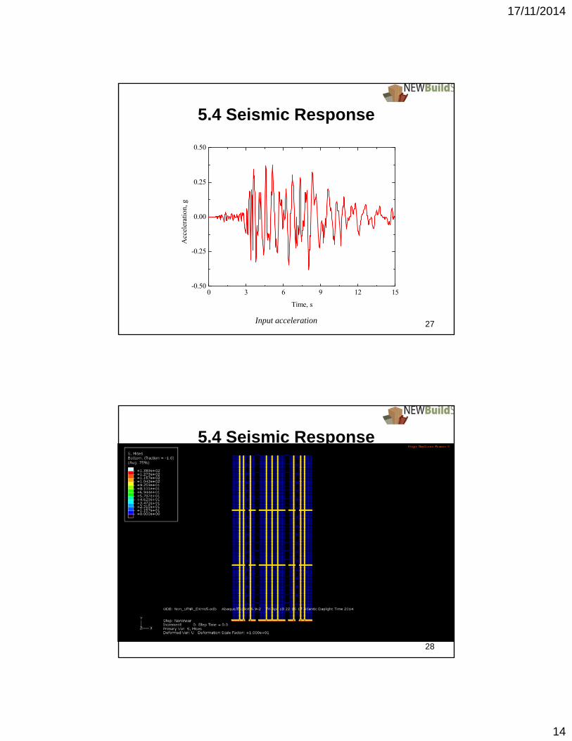
5.4 Seismic Response
Non-linear Time History Analysis Seismic response of the high-rise wood building is crucial in the ultimate
limit state.
Ten (10) “Far-Field” earthquake records were scaled at the corresponding fundamental period of the building model to match the spectral acceleration, Sa, of the Vancouver design spectrum.
0.01 0.1 1 101E-3
0.01
0.1
1
10
Spe
ctra
l Acc
eler
atio
n, S
a(g)
Period, T(s)
Target Spectrum Results Geom. Mean
26
17/11/2014
14
5.4 Seismic Response
27
0 3 6 9 12 15-0.50
-0.25
0.00
0.25
0.50
Acc
eler
atio
n, g
Time, s
Input acceleration
5.4 Seismic Response
28

17/11/2014
15
5.4 Seismic Response
29
0 3 6 9 12 15-6000
-3000
0
3000
6000
Bas
e sh
ear,
kN
Time, s
Base shear
5.4 Seismic Response
Non-linear Time History Analysis
0 2 4 6 8 104000
5000
6000
7000
8000
9000
Bas
e S
hear
, kN
No. of Earthquake Records
Non-linear P
max
Py of EEEP
Design Value
0 2 4 6 8 100.0
0.5
1.0
1.5
2.0
2.5
3.0
Inte
r-S
tore
y D
rift
Rat
io, %
No. of Earthquake Records
Non-linear Design Criterion
(a) Base shear (b) Inter-storey drift ratio
- All the base shears are less than the yield load of EEEP and the maximumcapacity derived by Pushover Analysis
- All inter-storey drift ratios are less than the design requirement of 2.5%.30

17/11/2014
16
6. Conclusions
31
Gravity loading analysis– the compressive deformation is small
Pushover analysis– the static load-carrying capacity and ductility are sufficient
Wind-induced response analysis– the deformation, through & across-wind accelerations are less than the limits
Non-linear time history seismic analysis– the inter-storey drift ratios are less than limit
20-storey timber buildings with the advanced products and connections are possible.
20-storey timber building
The End.Thanks for your attentions!
32