8e solutions manual_of_fundame
266
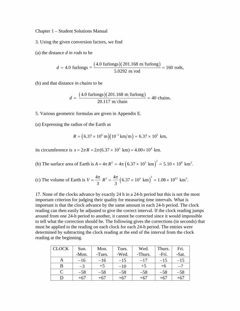
Chapter 1 – Student Solutions Manual 3. Using the given conversion factors, we find (a) the distance d in rods to be ( ) ( ) 4.0 furlongs 201.168 m furlong 4.0 furlongs = 160 rods, 5.0292 m rod d = = (b) and that distance in chains to be ( ) ( ) 4.0 furlongs 201.168 m furlong 40 chains. 20.117 m chain d = = 5. Various geometric formulas are given in Appendix E. (a) Expressing the radius of the Earth as ( ) ( ) 6 3 3 6.37 10 m 10 km m 6.37 10 km, R − = × = × its circumference is 3 4 2 2 (6.37 10 km) 4.00 10 km. s R π π = = × = × (b) The surface area of Earth is ( ) 2 2 3 4 4 6.37 10 km 5.10 10 km . A R = π = π × = × 8 2 (c) The volume of Earth is ( ) 3 3 3 4 4 6.37 10 km 1.08 10 km . 3 3 V R 12 3 π π = = × = × 17. None of the clocks advance by exactly 24 h in a 24-h period but this is not the most important criterion for judging their quality for measuring time intervals. What is important is that the clock advance by the same amount in each 24-h period. The clock reading can then easily be adjusted to give the correct interval. If the clock reading jumps around from one 24-h period to another, it cannot be corrected since it would impossible to tell what the correction should be. The following gives the corrections (in seconds) that must be applied to the reading on each clock for each 24-h period. The entries were determined by subtracting the clock reading at the end of the interval from the clock reading at the beginning. Sun. Mon. Tues. Wed. Thurs. Fri. CLOCK -Mon. -Tues. -Wed. -Thurs. -Fri. -Sat. A −16 −16 −15 −17 −15 −15 B −3 +5 −10 +5 +6 −7 C −58 −58 −58 −58 −58 −58 D +67 +67 +67 +67 +67 +67
-
Upload
ramil-jay-ureta -
Category
Documents
-
view
62.649 -
download
24
Transcript of 8e solutions manual_of_fundame
Chapter 1 – Student Solutions Manual 3. Using the given conversion factors, we find (a) the distance d in rods to be
( ) ( )4.0 furlongs 201.168 m furlong4.0 furlongs = 160 rods,
5.0292 m rodd = =
(b) and that distance in chains to be
( ) ( )4.0 furlongs 201.168 m furlong40 chains.
20.117 m chaind = =
5. Various geometric formulas are given in Appendix E. (a) Expressing the radius of the Earth as
( )( )6 3 36.37 10 m 10 km m 6.37 10 km,R −= × = × its circumference is 3 42 2 (6.37 10 km) 4.00 10 km.s Rπ π= = × = × (b) The surface area of Earth is ( )22 34 4 6.37 10 km 5.10 10 km .A R= π = π × = × 8 2
(c) The volume of Earth is ( )33 34 4 6.37 10 km 1.08 10 km .3 3
V R 12 3π π= = × = ×
17. None of the clocks advance by exactly 24 h in a 24-h period but this is not the most important criterion for judging their quality for measuring time intervals. What is important is that the clock advance by the same amount in each 24-h period. The clock reading can then easily be adjusted to give the correct interval. If the clock reading jumps around from one 24-h period to another, it cannot be corrected since it would impossible to tell what the correction should be. The following gives the corrections (in seconds) that must be applied to the reading on each clock for each 24-h period. The entries were determined by subtracting the clock reading at the end of the interval from the clock reading at the beginning.
Sun. Mon. Tues. Wed. Thurs. Fri. CLOCK -Mon. -Tues. -Wed. -Thurs. -Fri. -Sat.
A −16 −16 −15 −17 −15 −15 B −3 +5 −10 +5 +6 −7 C −58 −58 −58 −58 −58 −58 D +67 +67 +67 +67 +67 +67

E +70 +55 +2 +20 +10 +10 Clocks C and D are both good timekeepers in the sense that each is consistent in its daily drift (relative to WWF time); thus, C and D are easily made “perfect” with simple and predictable corrections. The correction for clock C is less than the correction for clock D, so we judge clock C to be the best and clock D to be the next best. The correction that must be applied to clock A is in the range from 15 s to 17s. For clock B it is the range from -5 s to +10 s, for clock E it is in the range from -70 s to -2 s. After C and D, A has the smallest range of correction, B has the next smallest range, and E has the greatest range. From best to worst, the ranking of the clocks is C, D, A, B, E. 21. We introduce the notion of density:
ρ =mV
and convert to SI units: 1 g = 1 × 10⁻³ kg. (a) For volume conversion, we find 1 cm3 = (1 × 10⁻²m)3 = 1 × 10⁻⁶m3. Thus, the density in kg/m3 is
3 33 3
3 6 3
1 g 10 kg cm1 g cm 1 10 kg m .cm g 10 m
−
−
⎛ ⎞ ⎛ ⎞⎛ ⎞= =⎜ ⎟ ⎜ ⎟⎜ ⎟⎝ ⎠ ⎝ ⎠ ⎝ ⎠
3×
Thus, the mass of a cubic meter of water is 1000 kg. (b) We divide the mass of the water by the time taken to drain it. The mass is found from M = ρV (the product of the volume of water and its density):
( ) ( )3 3 3 65700 m 1 10 kg m 5.70 10 kg.M = × = × The time is t = (10h)(3600 s/h) = 3.6 × 10⁴ s, so the mass flow rate R is
6
4
5.70 10 kg 158 kg s.3.6 10 s
MRt
×= = =
×
35. (a) Dividing 750 miles by the expected “40 miles per gallon” leads the tourist to believe that the car should need 18.8 gallons (in the U.S.) for the trip. (b) Dividing the two numbers given (to high precision) in the problem (and rounding off) gives the conversion between U.K. and U.S. gallons. The U.K. gallon is larger than the U.S gallon by a factor of 1.2. Applying this to the result of part (a), we find the answer for part (b) is 22.5 gallons.

39. Using the (exact) conversion 2.54 cm = 1 in. we find that 1 ft = (12)(2.54)/100 = 0.3048 m (which also can be found in Appendix D). The volume of a cord of wood is 8 × 4 × 4 = 128 ft3, which we convert (multiplying by 0.30483) to 3.6 m3. Therefore, one cubic meter of wood corresponds to 1/3.6 ≈ 0.3 cord. 41. (a) The difference between the total amounts in “freight” and “displacement” tons, (8 − 7)(73) = 73 barrels bulk, represents the extra M&M’s that are shipped. Using the conversions in the problem, this is equivalent to (73)(0.1415)(28.378) = 293 U.S. bushels. (b) The difference between the total amounts in “register” and “displacement” tons, (20 − 7)(73) = 949 barrels bulk, represents the extra M&M’s are shipped. Using the conversions in the problem, this is equivalent to (949)(0.1415)(28.378) = 3.81 × 10³ U.S. bushels. 45. We convert meters to astronomical units, and seconds to minutes, using
8
1000 m 1 km1 AU 1.50 10 km60 s 1 min .
=
= ×=
Thus, 3.0 × 10⁸ m/s becomes
8
8
3.0 10 m 1 km AU 60 s 0.12 AU min.s 1000 m 1.50 10 km min
⎛ ⎞ ⎛ ⎞ ⎛ ⎞ ⎛ ⎞× ⎟ ⎟ ⎟⎜ ⎜ ⎜ ⎟⎜⎟ ⎟ ⎟ =⎜ ⎟⎜ ⎜ ⎜⎟ ⎟ ⎟ ⎟⎟⎜ ⎜ ⎜ ⎜⎟ ⎟⎟ ⎜ ⎜⎜ ⎝ ⎠×⎝ ⎠ ⎝ ⎠⎝ ⎠
57. (a) When θ is measured in radians, it is equal to the arc length s divided by the radius R. For a very large radius circle and small value of θ, such as we deal with in Fig. 1–9, the arc may be approximated as the straight line-segment of length 1 AU. First, we convert θ = 1 arcsecond to radians:
( ) 1 arcminute 1 2 radian1 arcsecond60 arcsecond 60 arcminute 360
⎛ ⎞ ⎛ ⎞° π⎛ ⎞⎜ ⎟ ⎜ ⎟ ⎜ ⎟°⎝ ⎠⎝ ⎠ ⎝ ⎠
which yields θ = 4.85 × 10⁻⁶ rad. Therefore, one parsec is
R so
AU4.85 10
AU.= =×
= ×−θ1 2 06 106
5.
Now we use this to convert R = 1 AU to parsecs:
R =×
FHG
IKJ = × −1 1 4 9 10 6AU pc
2.06 10 AUpc.5b g .
(b) Also, since it is straightforward to figure the number of seconds in a year (about 3.16 × 10⁷ s), and (for constant speeds) distance = speed × time, we have
1 316 10 5 9 107 1ly = 186,000 mi s s mia f c h. .× × 2
which we convert to AU by dividing by 92.6 × 10⁶ (given in the problem statement), obtaining 6.3 × 10⁴ AU. Inverting, the result is 1 AU = 1/6.3 × 104 = 1.6 × 10⁻⁵ ly.

Chapter 2 – Student Solutions Manual 1. We use Eq. 2-2 and Eq. 2-3. During a time tc when the velocity remains a positive constant, speed is equivalent to velocity, and distance is equivalent to displacement, with Δx = v tc. (a) During the first part of the motion, the displacement is Δx1 = 40 km and the time interval is
t140 133= =
( . km)(30 km / h)
h.
During the second part the displacement is Δx2 = 40 km and the time interval is
t240 0 67= =
( . km)(60 km / h)
h.
Both displacements are in the same direction, so the total displacement is
Δx = Δx1 + Δx2 = 40 km + 40 km = 80 km. The total time for the trip is t = t1 + t2 = 2.00 h. Consequently, the average velocity is
vavg km)
(2.0 h) km / h.= =
(80 40
(b) In this example, the numerical result for the average speed is the same as the average velocity 40 km/h. (c) As shown below, the graph consists of two contiguous line segments, the first having a slope of 30 km/h and connecting the origin to (t1, x1) = (1.33 h, 40 km) and the second having a slope of 60 km/h and connecting (t1, x1) to (t, x) = (2.00 h, 80 km). From the graphical point of view, the slope of the dashed line drawn from the origin to (t, x) represents the average velocity.

5. Using x = 3t – 4t2 + t3 with SI units understood is efficient (and is the approach we will use), but if we wished to make the units explicit we would write
x = (3 m/s)t – (4 m/s2)t2 + (1 m/s3)t3. We will quote our answers to one or two significant figures, and not try to follow the significant figure rules rigorously. (a) Plugging in t = 1 s yields x = 3 – 4 + 1 = 0. (b) With t = 2 s we get x = 3(2) – 4(2)2+(2)3 = –2 m. (c) With t = 3 s we have x = 0 m. (d) Plugging in t = 4 s gives x = 12 m. For later reference, we also note that the position at t = 0 is x = 0. (e) The position at t = 0 is subtracted from the position at t = 4 s to find the displacement Δx = 12 m. (f) The position at t = 2 s is subtracted from the position at t = 4 s to give the displacement Δx = 14 m. Eq. 2-2, then, leads to
avg14 m 7 m/s.
2 sxvt
Δ= = =Δ
(g) The horizontal axis is 0 ≤ t ≤ 4 with SI units understood. Not shown is a straight line drawn from the point at (t, x) = (2, –2) to the highest point shown (at t = 4 s) which would represent the answer for part (f).
19. We represent its initial direction of motion as the +x direction, so that v0 = +18 m/s and v = –30 m/s (when t = 2.4 s). Using Eq. 2-7 (or Eq. 2-11, suitably interpreted) we find

2avg
( 30 m/s) ( 1 m/s) 20 m/s2.4 s
a − − += = −
which indicates that the average acceleration has magnitude 20 m/s2 and is in the opposite direction to the particle’s initial velocity. 25. The constant acceleration stated in the problem permits the use of the equations in Table 2-1. (a) We solve v = v0 + at for the time:
t v va
=−
=×
= ×01
108
63 0 109 8
31 10( ..
. m / s) m / s
s2
which is equivalent to 1.2 months. (b) We evaluate x x v t at= + +0 0
12
2 , with x0 = 0. The result is
( )2 6 2 131 9.8 m/s (3.1 10 s) 4.6 10 m .2
x = × = ×
27. Assuming constant acceleration permits the use of the equations in Table 2-1. We solve v v with xa x x2
02
02= + −( ) 0 = 0 and x = 0.010 m. Thus,
2 2 5 2 5 2
15 20 (5.7 10 m/s) (1.5 10 m/s) 1.62 10 m/s .2 2(0.010 m)
v vax− × − ×
= = = ×
33. The problem statement (see part (a)) indicates that a = constant, which allows us to use Table 2-1. (a) We take x0 = 0, and solve x = v0t + 1
2 at2 (Eq. 2-15) for the acceleration: a = 2(x – v0t)/t2. Substituting x = 24.0 m, v0 = 56.0 km/h = 15.55 m/s and t = 2.00 s, we find
( ) ( )( )( )
22
2 24.0m 15.55m/s 2.00s3.56m/s ,
2.00sa
−= = −
or . The negative sign indicates that the acceleration is opposite to the direction of motion of the car. The car is slowing down.
2| | 3.56 m/sa =
(b) We evaluate v = v0 + at as follows:
v = − =1555 356 2 00 8 43. . . .m / s m / s s m / s2c h b g
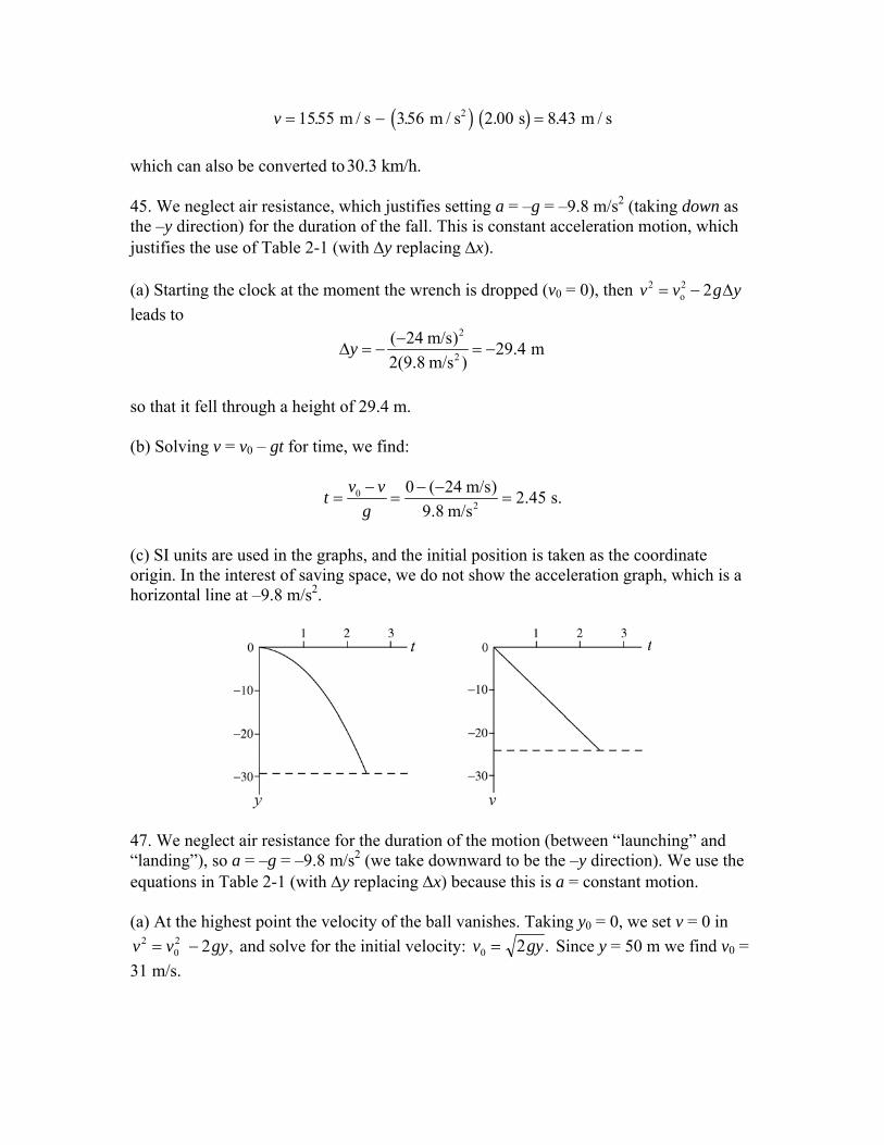
which can also be converted to30.3 km /h. 45. We neglect air resistance, which justifies setting a = –g = –9.8 m/s2 (taking down as the –y direction) for the duration of the fall. This is constant acceleration motion, which justifies the use of Table 2-1 (with Δy replacing Δx). (a) Starting the clock at the moment the wrench is dropped (v0 = 0), then leads to
2 2o 2v v g= − Δy
2
2
( 24 m/s) 29.4 m2(9.8 m/s )
y −Δ = − = −
so that it fell through a height of 29.4 m. (b) Solving v = v0 – gt for time, we find:
02
0 ( 24 m/s) 2.45 s.9.8 m/s
v vtg− − −
= = =
(c) SI units are used in the graphs, and the initial position is taken as the coordinate origin. In the interest of saving space, we do not show the acceleration graph, which is a horizontal line at –9.8 m/s2.
47. We neglect air resistance for the duration of the motion (between “launching” and “landing”), so a = –g = –9.8 m/s2 (we take downward to be the –y direction). We use the equations in Table 2-1 (with Δy replacing Δx) because this is a = constant motion. (a) At the highest point the velocity of the ball vanishes. Taking y0 = 0, we set v = 0 in
and solve for the initial velocity: v v gy202 2= − , v g0 2= .y Since y = 50 m we find v0 =
31 m/s.

(b) It will be in the air from the time it leaves the ground until the time it returns to the ground (y = 0). Applying Eq. 2-15 to the entire motion (the rise and the fall, of total time t > 0) we have
y v t gt t vg
= − ⇒ =02 01
22
which (using our result from part (a)) produces t = 6.4 s. It is possible to obtain this without using part (a)’s result; one can find the time just for the rise (from ground to highest point) from Eq. 2-16 and then double it. (c) SI units are understood in the x and v graphs shown. In the interest of saving space, we do not show the graph of a, which is a horizontal line at –9.8 m/s2.
49. We neglect air resistance, which justifies setting a = –g = –9.8 m/s2 (taking down as the –y direction) for the duration of the motion. We are allowed to use Table 2-1 (with Δy replacing Δx) because this is constant acceleration motion. We are placing the coordinate origin on the ground. We note that the initial velocity of the package is the same as the velocity of the balloon, v0 = +12 m/s and that its initial coordinate is y0 = +80 m. (a) We solve y y v t gt= + −0 0
12
2 for time, with y = 0, using the quadratic formula (choosing the positive root to yield a positive value for t).
tv v gy
g=
+ +=
+ +=0 0
20
22 12 12 2 9 8 809 8
54.
..
b gb gs
(b) If we wish to avoid using the result from part (a), we could use Eq. 2-16, but if that is not a concern, then a variety of formulas from Table 2-1 can be used. For instance, Eq. 2-11 leads to
v = v0 – gt = 12 – (9.8)(5.4) = – 41 m/s.
Its final speed is 41 m/s.
51. The speed of the boat is constant, given by vb = d/t. Here, d is the distance of the boat from the bridge when the key is dropped (12 m) and t is the time the key takes in falling. To calculate t, we put the origin of the coordinate system at the point where the key is dropped and take the y axis to be positive in the downward direction. Taking the time to be zero at the instant the key is dropped, we compute the time t when y = 45 m. Since the initial velocity of the key is zero, the coordinate of the key is given by y gt= 1
22 . Thus
t yg
= = =2 2 45 3 03( . m)
9.8 m / s s .2
Therefore, the speed of the boat is
vb = =12 4 0 m3.03 s
m / s ..
55. (a) We first find the velocity of the ball just before it hits the ground. During contact with the ground its average acceleration is given by
a vtavg =
ΔΔ
where Δv is the change in its velocity during contact with the ground and
is the duration of contact. Now, to find the velocity just before contact, we put the origin at the point where the ball is dropped (and take +y upward) and take t = 0 to be when it is dropped. The ball strikes the ground at y = –15.0 m. Its velocity there is found from Eq. 2-16: v
320.0 10 st −Δ = ×
2 = –2gy. Therefore,
v gy= − − = − − − = −2 2 9 8 150 171( . )( . ) . m / s where the negative sign is chosen since the ball is traveling downward at the moment of contact. Consequently, the average acceleration during contact with the ground is
aavg2 m / s=
− −×
=−
0 17 120 0 10
8573
( . ).
.
89. Integrating (from t = 2 s to variable t = 4 s) the acceleration to get the velocity (and using the velocity datum mentioned in the problem, leads to
v = 17 + 12 (5)(42 – 22) = 47 m/s. 91. We take +x in the direction of motion, so
v =FHG
IKJ = +60 1000
360016 7km / h m / km
s / hm / sb g .
and a > 0. The location where it starts from rest (v0 = 0) is taken to be x0 = 0. (a) Eq. 2-7 gives aavg = (v – v0)/t where t = 5.4 s and the velocities are given above. Thus, aavg = 3.1 m/s2. (b) The assumption that a = constant permits the use of Table 2-1. From that list, we choose Eq. 2-17:
( ) ( )( )01 1 16.7 m/s 5.4 s 45 m.2 2
x v v t= + = =
(c) We use Eq. 2-15, now with x = 250 m:
( )22
2 250 m1 22 3
xx at ta
= ⇒ = =.1 m/s
which yields t = 13 s. 97. The (ideal) driving time before the change was t = Δx/v, and after the change it is t' = Δx/v'. The time saved by the change is therefore
t t xv v
x x− = −FHGIKJ = −FHG
IKJ ='
'.Δ Δ Δ
1 1 155
165
0 0028 h / mib g which becomes, converting Δx = 700/1.61 = 435 mi (using a conversion found on the inside front cover of the textbook), t – t' = (435)(0.0028) = 1.2 h. This is equivalent to 1 h and 13 min. 99. We neglect air resistance, which justifies setting a = –g = –9.8 m/s2 (taking down as the –y direction) for the duration of the motion. We are allowed to use Table 2-1 (with Δy replacing Δx) because this is constant acceleration motion. When something is thrown straight up and is caught at the level it was thrown from (with a trajectory similar to that shown in Fig. 2-31), the time of flight t is half of its time of ascent ta, which is given by Eq. 2-18 with Δy = H and v = 0 (indicating the maximum point).
H vt gt t Hga a a= + ⇒ =
12
22
Writing these in terms of the total time in the air t = 2ta we have

H gt t Hg
= ⇒ =18
2 22 .
We consider two throws, one to height H1 for total time t1 and another to height H2 for total time t2, and we set up a ratio:
HH
gtgt
tt
2
1
18 2
2
18 1
22
1
2
= =FHGIKJ
from which we conclude that if t2 = 2t1 (as is required by the problem) then H2 = 22H1 = 4H1. 107. (a) The wording of the problem makes it clear that the equations of Table 2-1 apply, the challenge being that v0, v, and a are not explicitly given. We can, however, apply x – x0 = v0t + 12at2 to a variety of points on the graph and solve for the unknowns from the simultaneous equations. For instance,
16 – 0 = v0(2.0) + 12 a(2.0)2
27 – 0 = v0(3.0) + 12 a(3.0)2
lead to the values v0 = 6.0 m/s and a = 2.0 m/s2. (b) From Table 2-1,
x – x0 = vt – 12at2 ⇒ 27 – 0 = v(3.0) –
12 (2.0)(3.0)2
which leads to v = 12 m/s. (c) Assuming the wind continues during 3.0 ≤ t ≤ 6.0, we apply x – x0 = v0t + 12at2 to this interval (where v0 = 12.0 m/s from part (b)) to obtain
Δx = (12.0)(3.0) + 12 (2.0)(3.0)2 = 45 m .
Chapter 3 – Student Solutions Manual 1. A vector can be represented in the magnitude-angle notation (a, θ), where a 2 2
x ya a a= + is the magnitude and
1tan y
x
aa
θ − ⎛ ⎞= ⎜ ⎟
⎝ ⎠
is the angle makes with the positive x axis. a (a) Given Ax = −25.0 m and Ay = 40.0 m, 2 2( 25.0 m) (40.0 m) 47.2 mA = − + = (b) Recalling that tan θ = tan (θ + 180°), tan–1 [40/ (– 25)] = – 58° or 122°. Noting that the vector is in the third quadrant (by the signs of its x and y components) we see that 122° is the correct answer. The graphical calculator “shortcuts” mentioned above are designed to correctly choose the right possibility. 3. The x and the y components of a vector a lying on the xy plane are given by
cos , sinx ya a a aθ θ= = where is the magnitude and θ is the angle between | |a a= a and the positive x axis. (a) The x component of is given by aa x = 7.3 cos 250° = – 2.5 m. (b) and the y component is given by ay = 7.3 sin 250° = – 6.9 m. In considering the variety of ways to compute these, we note that the vector is 70° below the – x axis, so the components could also have been found from ax = – 7.3 cos 70° and ay = – 7.3 sin 70°. In a similar vein, we note that the vector is 20° to the left from the – y axis, so one could use ax = – 7.3 sin 20° and ay = – 7.3 cos 20° to achieve the same results. 7. The length unit meter is understood throughout the calculation. (a) We compute the distance from one corner to the diametrically opposite corner:
2 2 23.00 3.70 4.30 6.42d = + + = .
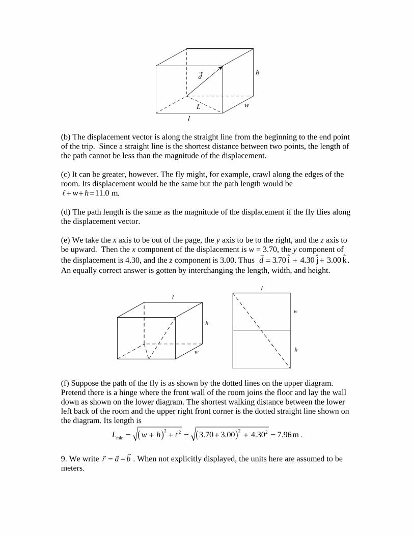
(b) The displacement vector is along the straight line from the beginning to the end point of the trip. Since a straight line is the shortest distance between two points, the length of the path cannot be less than the magnitude of the displacement. (c) It can be greater, however. The fly might, for example, crawl along the edges of the room. Its displacement would be the same but the path length would be
11.0 m.w h+ + = (d) The path length is the same as the magnitude of the displacement if the fly flies along the displacement vector. (e) We take the x axis to be out of the page, the y axis to be to the right, and the z axis to be upward. Then the x component of the displacement is w = 3.70, the y component of the displacement is 4.30, and the z component is 3.00. Thus d . An equally correct answer is gotten by interchanging the length, width, and height.
= + +3 70. i 4.30 j 3.00 k
(f) Suppose the path of the fly is as shown by the dotted lines on the upper diagram. Pretend there is a hinge where the front wall of the room joins the floor and lay the wall down as shown on the lower diagram. The shortest walking distance between the lower left back of the room and the upper right front corner is the dotted straight line shown on the diagram. Its length is
( ) ( )2 22 2min 3.70 3.00 4.30 7.96m .L w h= + + = + + =
9. We write r a b= + . When not explicitly displayed, the units here are assumed to be meters.

(a) The x and the y components of r are rx = ax + bx = (4.0 m) – (13 m) = –9.0 m and ry = ay + by = (3.0 m) + (7.0 m) = 10 m, respectively. Thus ˆ ˆ( 9.0m) i (10 m) jr = − + . (b) The magnitude of r is 2 2 2 2| | ( 9.0 m) (10 m) 13 mx yr r r r= = + = − + = . (c) The angle between the resultant and the +x axis is given by
θ = tan–1(ry/rx) = tan–1 [(10 m)/( –9.0 m)] = – 48° or 132°. Since the x component of the resultant is negative and the y component is positive, characteristic of the second quadrant, we find the angle is 132° (measured counterclockwise from +x axis). 17. It should be mentioned that an efficient way to work this vector addition problem is with the cosine law for general triangles (and since a b, and r form an isosceles triangle, the angles are easy to figure). However, in the interest of reinforcing the usual systematic approach to vector addition, we note that the angle b makes with the +x axis is 30° +105° = 135° and apply Eq. 3-5 and Eq. 3-6 where appropriate. (a) The x component of r is rx = (10.0 m) cos 30° + (10.0 m) cos 135° = 1.59 m. (b) The y component of r is ry = (10.0 m) sin 30° + (10.0 m) sin 135° = 12.1 m. (c) The magnitude of r is 2 2| | (1.59 m) (12.1 m) 12.2 m.r r= = + = (d) The angle between r and the +x direction is tan–1[(12.1 m)/(1.59 m)] = 82.5°. 39. Since ab cos φ = axbx + ayby + azbz,
cos .φ =+ +a b a b a b
abx x y y z z
The magnitudes of the vectors given in the problem are
2 2 2
2 2 2
| | (3.00) (3.00) (3.00) 5.20
| | (2.00) (1.00) (3.00) 3.74.
a a
b b
= = + + =
= = + + =
The angle between them is found from

(3.00) (2.00) (3.00) (1.00) (3.00) (3.00)cos 0.926.(5.20) (3.74)
φ + += =
The angle is φ = 22°. 43. From the figure, we note that c b⊥ , which implies that the angle between and the +x axis is 120°. Direct application of Eq. 3-5 yields the answers for this and the next few parts.
c
(a) ax = a cos 0° = a = 3.00 m. (b) ay = a sin 0° = 0. (c) bx = b cos 30° = (4.00 m) cos 30° = 3.46 m. (d) by = b sin 30° = (4.00 m) sin 30° = 2.00 m. (e) cx = c cos 120° = (10.0 m) cos 120° = –5.00 m. (f) cy = c sin 30° = (10.0 m) sin 120° = 8.66 m. (g) In terms of components (first x and then y), we must have
5.00 m (3.00 m) (3.46 m) 8.66 m (0) (2.00 m).
p qp q
− = += +
Solving these equations, we find p = –6.67. (h) And q = 4.33 (note that it’s easiest to solve for q first). The numbers p and q have no units. 47. We apply Eq. 3-20 and Eq. 3-27. (a) The scalar (dot) product of the two vectors is
cos (10) (6.0) cos 60 30.a b ab φ⋅ = = ° =
(b) The magnitude of the vector (cross) product of the two vectors is
| | sin (10) (6.0) sin 60 5a b ab φ× = = ° = 2. 51. Let A
→ represent the first part of his actual voyage (50.0 km east) and C
→ represent
the intended voyage (90.0 km north). We are looking for a vector B →
such that A →
+ B →
= C
→.

(a) The Pythagorean theorem yields 2 2(50.0) (90.0) 103 km.B = + = (b) The direction is 1tan (50.0 / 90.0) 29.1− = ° west of north (which is equivalent to 60.9° north of due west). 71. Given: A
→ + B
→ =6.0 i^ + 1.0 j^ and A
→ – B
→ = – 4.0 i^ + 7.0 j^ . Solving these
simultaneously leads to A →
=1.0 i^ + 4.0 j^. The Pythagorean theorem then leads to 2 2(1.0) (4.0) 4.1A = + = .

Chapter 4 – Student Solutions Manual 11. We apply Eq. 4-10 and Eq. 4-16.
(a) Taking the derivative of the position vector with respect to time, we have, in SI units (m/s),
2ˆ ˆ ˆ ˆ = (i + 4 j + k) = 8 j + k .dv t t tdt
ˆ
(b) Taking another derivative with respect to time leads to, in SI units (m/s2),
ˆ ˆ ˆ= (8 j + k) = 8 j .da tdt
17. Constant acceleration in both directions (x and y) allows us to use Table 2-1 for the motion along each direction. This can be handled individually (for Δx and Δy) or together with the unit-vector notation (for Δr). Where units are not shown, SI units are to be understood. (a) The velocity of the particle at any time t is given by v v at= +0 , where is the initial velocity and is the (constant) acceleration. The x component is v
v0
a x = v0x + axt = 3.00 – 1.00t, and the y component is vy = v0y + ayt = –0.500t since v0y = 0. When the particle reaches its maximum x coordinate at t = tm, we must have vx = 0. Therefore, 3.00 – 1.00tm = 0 or tm = 3.00 s. The y component of the velocity at this time is
vy = 0 – 0.500(3.00) = –1.50 m/s; this is the only nonzero component of v at tm. (b) Since it started at the origin, the coordinates of the particle at any time t are given by r v t at= +0
12
2 . At t = tm this becomes
( )( ) ( )( )21ˆ ˆ ˆ ˆ3.00i 3.00 1.00 i 0.50 j 3.00 (4.50 i 2.25 j) m.2
r = + − − = − ˆ
29. The initial velocity has no vertical component — only an x component equal to +2.00 m/s. Also, y0 = +10.0 m if the water surface is established as y = 0. (a) x – x0 = vxt readily yields x – x0 = 1.60 m. (b) Using y y v t gty− = −0 0
12
2 , we obtain y = 6.86 m when t = 0.800 s and v0y=0.

(c) Using the fact that y = 0 and y0 = 10.0, the equation y y v t gty− = −0 012
2 leads to 22(10.0 m) / 9.80 m/s 1.43 st = = . During this time, the x-displacement of the diver
is x – x0 = (2.00 m/s)(1.43 s) = 2.86 m. 31. We adopt the positive direction choices used in the textbook so that equations such as Eq. 4-22 are directly applicable. The coordinate origin is at ground level directly below the release point. We write θ0 = –37.0° for the angle measured from +x, since the angle given in the problem is measured from the –y direction. We note that the initial speed of the projectile is the plane’s speed at the moment of release. (a) We use Eq. 4-22 to find v0:
2 2 20 0 0 0
1 1 ( sin ) 0 730 m sin( 37.0 )(5.00 s) (9.80 m/s )(5.00 s)2 2
y y v t gt vθ− = − ⇒ − = − ° −
which yields v0 = 202 m/s. (b) The horizontal distance traveled is x = v0tcos θ0 = (202 m/s)(5.00 s)cos(–37.0°) = 806 m. (c) The x component of the velocity (just before impact) is
vx = v0cosθ0 = (202 m/s)cos(–37.0°) = 161 m/s. (d) The y component of the velocity (just before impact) is
vy = v0 sin θ0 – gt = (202 m/s) sin (–37.0°) – (9.80 m/s2)(5.00 s) = –171 m/s. 39. We adopt the positive direction choices used in the textbook so that equations such as Eq. 4-22 are directly applicable. The coordinate origin is at the end of the rifle (the initial point for the bullet as it begins projectile motion in the sense of § 4-5), and we let θ0 be the firing angle. If the target is a distance d away, then its coordinates are x = d, y = 0. The projectile motion equations lead to d = v0t cos θ0 and 0 0 0
12
2= −v t gtsinθ . Eliminating t leads to 2 00
20 0v gsin cos dθ θ − = . Using sin cos sinθ θ θ0 0
12 02= b g , we
obtain
220 0 0 2 2
0
(9.80 m/s )(45.7 m)sin (2 ) sin(2 )(460 m/s)
gdv gdv
θ θ= ⇒ = =
which yields 3
0sin(2 ) 2.11 10θ −= × and consequently θ0 = 0.0606°. If the gun is aimed at a point a distance above the target, then tan θ 0 = d so that
0tan (45.7 m) tan(0.0606 ) 0.0484 m 4.84 cm.d θ= = ° = =
47. We adopt the positive direction choices used in the textbook so that equations such as Eq. 4-22 are directly applicable. The coordinate origin is at ground level directly below impact point between bat and ball. The Hint given in the problem is important, since it provides us with enough information to find v0 directly from Eq. 4-26. (a) We want to know how high the ball is from the ground when it is at x = 97.5 m, which requires knowing the initial velocity. Using the range information and θ0 = 45°, we use Eq. 4-26 to solve for v0:
( )( )2
00
9.8 m/s 107 m32.4 m/s.
sin 2 1gRvθ
= = =
Thus, Eq. 4-21 tells us the time it is over the fence:
( )0 0
97.5 m 4.26 s.cos 32.4 m/s cos 45xt
v θ= = =
°
At this moment, the ball is at a height (above the ground) of
y y v t gt= + − =0 0 021
29 88sin .θb g m
which implies it does indeed clear the 7.32 m high fence. (b) At t = 4.26 s, the center of the ball is 9.88 m – 7.32 m = 2.56 m above the fence. 51. We adopt the positive direction choices used in the textbook so that equations such as Eq. 4-22 are directly applicable. The coordinate origin is at the point where the ball is kicked. We use x and y to denote the coordinates of ball at the goalpost, and try to find the kicking angle(s) θ0 so that y = 3.44 m when x = 50 m. Writing the kinematic equations for projectile motion:
210 0 0 0 2cos , sin ,x v y v tθ θ= = − gt
we see the first equation gives t = x/v0 cos θ0, and when this is substituted into the second the result is
y x gxv
= −tancos
.θθ0
2
02 2
02
One may solve this by trial and error: systematically trying values of θ0 until you find the two that satisfy the equation. A little manipulation, however, will give an algebraic solution: Using the trigonometric identity 1 / cos2 θ0 = 1 + tan2 θ0, we obtain

12
12
02
02
20 0
2
02
gxv
x y gxv
tan tanθ θ− + + =
which is a second-order equation for tan θ0. To simplify writing the solution, we denote
( )( ) ( )2 22 2 21 102 2/ 9.80 m/s 50 m / 25 m/s 19.6m.c gx v= = = Then the second-order
equation becomes c tan2 θ0 – x tan θ0 + y + c = 0. Using the quadratic formula, we obtain its solution(s).
( ) ( )( )( )
2 2
0
4 50 m (50 m) 4 3.44 m 19.6 m 19.6 mtan .
2 2 19.6 mx x y c c
cθ
± − + ± − += =
The two solutions are given by tan θ0 = 1.95 and tan θ0 = 0.605. The corresponding (first-quadrant) angles are θ0 = 63° and θ0 = 31°. Thus, (a) The smallest elevation angle is θ0 = 31°, and (b) The greatest elevation angle is θ0 = 63°. If kicked at any angle between these two, the ball will travel above the cross bar on the goalposts. 53. We denote h as the height of a step and w as the width. To hit step n, the ball must fall a distance nh and travel horizontally a distance between (n – 1)w and nw. We take the origin of a coordinate system to be at the point where the ball leaves the top of the stairway, and we choose the y axis to be positive in the upward direction. The coordinates of the ball at time t are given by x = v0xt and y g= − 1
22t (since v0y = 0). We equate y to
–nh and solve for the time to reach the level of step n:
t nhg
=2 .
The x coordinate then is
0 2
2 2 (0.203 m)(1.52 m/s) (0.309 m) .9.8 m/sx
nh nx v ng
= = =
The method is to try values of n until we find one for which x/w is less than n but greater than n – 1. For n = 1, x = 0.309 m and x/w = 1.52, which is greater than n. For n = 2, x = 0.437 m and x/w = 2.15, which is also greater than n. For n = 3, x = 0.535 m and x/w = 2.64. Now, this is less than n and greater than n – 1, so the ball hits the third step.
67. To calculate the centripetal acceleration of the stone, we need to know its speed during its circular motion (this is also its initial speed when it flies off). We use the kinematic equations of projectile motion (discussed in §4-6) to find that speed. Taking the +y direction to be upward and placing the origin at the point where the stone leaves its circular orbit, then the coordinates of the stone during its motion as a projectile are given by x = v0t and y g= − 1
22t (since v0y = 0). It hits the ground at x = 10 m and y = –2.0 m.
Formally solving the second equation for the time, we obtain t y= −2 / g , which we substitute into the first equation:
v x gy0 2
10 9 82 2 0
15 7= − = −−
=m m / sm
m / s.2
b g b g.
..
Therefore, the magnitude of the centripetal acceleration is
a vr
= = =2 2
215715
160..
.m / sm
m / sb g
75. Relative to the car the velocity of the snowflakes has a vertical component of 8.0 m/s and a horizontal component of 50 km/h = 13.9 m/s. The angle θ from the vertical is found from
13.9 m/stan 1.748.0 m/s
h
v
vv
θ = = =
which yields θ = 60°. 77. Since the raindrops fall vertically relative to the train, the horizontal component of the velocity of a raindrop is vh = 30 m/s, the same as the speed of the train. If vv is the vertical component of the velocity and θ is the angle between the direction of motion and the vertical, then tan θ = vh/vv. Thus vv = vh/tan θ = (30 m/s)/tan 70° = 10.9 m/s. The speed of a raindrop is
v v vh v= + = + =2 2 30 10 9 32( ( . m / s) m / s) m / s2 2 . 91. We adopt the positive direction choices used in the textbook so that equations such as Eq. 4-22 are directly applicable. (a) With the origin at the firing point, the y coordinate of the bullet is given by y g= − 1
22t . If t is the time of flight and y = – 0.019 m indicates where the bullet hits the
target, then

( ) 22
2 0.019 m6.2 10 s.
9.8 m/st −= = ×
(b) The muzzle velocity is the initial (horizontal) velocity of the bullet. Since x = 30 m is the horizontal position of the target, we have x = v0t. Thus,
20 2
30 m 4.8 10 m/s.6.3 10 s
xvt −= = = ×
×
107. (a) Eq. 2-15 can be applied to the vertical (y axis) motion related to reaching the maximum height (when t = 3.0 s and vy = 0):
ymax – y0 = vyt – 12gt2 .
With ground level chosen so y0 = 0, this equation gives the result ymax = 12 g(3.0 s)2 = 44 m. (b) After the moment it reached maximum height, it is falling; at t = 2.5 s, it will have fallen an amount given by Eq. 2-18
yfence – ymax = (0)(2.5 s) – 12 g(2.5 s)2
which leads to yfence = 13 m. (c) Either the range formula, Eq. 4-26, can be used or one can note that after passing the fence, it will strike the ground in 0.5 s (so that the total "fall-time" equals the "rise-time"). Since the horizontal component of velocity in a projectile-motion problem is constant (neglecting air friction), we find the original x-component from 97.5 m = v0x(5.5 s) and then apply it to that final 0.5 s. Thus, we find v0x = 17.7 m/s and that after the fence
Δx = (17.7 m/s)(0.5 s) = 8.9 m. 111. Since the x and y components of the acceleration are constants, we can use Table 2-1 for the motion along both axes. This can be handled individually (for Δx and Δy) or together with the unit-vector notation (for Δr). Where units are not shown, SI units are to be understood. (a) Since , the position vector of the particle is (adapting Eq. 2-15) r0 0=
( ) ( ) ( ) ( )2 2 20
1 1ˆ ˆ ˆ ˆ8.0 j 4.0 i 2.0 j 2.0 i + 8.0 + 1.0 j.2 2
r v t at t t t t t= + = + + = 2 ˆ

Therefore, we find when x = 29 m, by solving 2.0t2 = 29, which leads to t = 3.8 s. The y coordinate at that time is y = (8.0 m/s)(3.8 s) + (1.0 m/s2)(3.8 s)2 = 45 m. (b) Adapting Eq. 2-11, the velocity of the particle is given by
v v at= +0 . Thus, at t = 3.8 s, the velocity is
( )( )2 2ˆ ˆ ˆ ˆ(8.0 m/s) j (4.0 m/s ) i (2.0 m/s ) j 3.8 s (15.2 m/s) i (15.6 m/s) jv = + + = + ˆ
which has a magnitude of
2 2 2 2(15.2 m/s) (15.6 m/s) 22 m/s.x yv v v= + = + = 121. On the one hand, we could perform the vector addition of the displacements with a vector-capable calculator in polar mode ((75 37 ) + (65 90 ) = (63 18 )),∠ ° ∠ − ° ∠ − ° but in keeping with Eq. 3-5 and Eq. 3-6 we will show the details in unit-vector notation. We use a ‘standard’ coordinate system with +x East and +y North. Lengths are in kilometers and times are in hours. (a) We perform the vector addition of individual displacements to find the net displacement of the camel.
1
2
1 2
ˆ ˆ = (75 km)cos(37 ) i (75 km) sin(37 ) jˆ =( 65 km) j
ˆ ˆ + = (60 km) i (20 km ) j .
r
r
r r r
Δ ° +
Δ −
Δ = Δ Δ −
°
If it is desired to express this in magnitude-angle notation, then this is equivalent to a vector of length 2 2| | (60 km) +( 20 km) = 63 kmrΔ = − . (b) The direction of is , or 18 south of east. rΔ 1tan [( 20 km) /(60 km)] 18θ −= − = − ° ° (c) We use the result from part (a) in Eq. 4-8 along with the fact that Δt = 90 h. In unit vector notation, we obtain
avg
ˆ ˆ(60 i 20 j) km ˆ ˆ= = (0.67 i 0.22 j) km/h.90 h
v −−
This leads to avg| | = 0.70 km/h.v

(d) The direction of is , or 18 south of east.
avgv 1tan [( 0.22 km/h) /(0.67 km/h)] 18θ −= − = − ° °
(e) The average speed is distinguished from the magnitude of average velocity in that it depends on the total distance as opposed to the net displacement. Since the camel travels 140 km, we obtain (140 km)/(90 h) = 1.56 km/h 1.6 km/h≈ . (f) The net displacement is required to be the 90 km East from A to B. The displacement from the resting place to B is denoted 3.rΔ Thus, we must have
1 2 3ˆ+ + = (90 km) ir r rΔ Δ Δ
which produces in unit-vector notation, or in magnitude-angle notation. Therefore, using Eq. 4-8 we obtain
3ˆ(30 km)i (20 km)jrΔ = + ˆ (36 33 )∠ °
avg36 km| | = = 1.2 km/h.
(120 90) hv
−
(g) The direction of is the same as avgv r3 (that is, 33° north of east).

Chapter 5 – Student Solutions Manual 5. We denote the two forces F1 and F2
1−. According to Newton’s second law,
F F ma F ma F1 2 2+ == so, . (a) In unit vector notation F1 20 0= . N ib g and
( ) ( ) ( ) ( )2 2 2ˆ ˆˆ12.0 sin 30.0 m/s i 12.0 cos 30.0 m/s 6.00 m/s i 10.4m/s j.ja = − ° − ° = − − 2 ˆ Therefore,
( ) ( ) ( ) ( ) ( )( ) ( )
2 22
ˆ ˆ2.00kg 6.00 m/s i 2.00 kg 10.4 m/s j 20.0 N iˆ ˆ32.0 N i 20.8 N j.
F = − + − −
= − −
ˆ
(b) The magnitude of is F2
2 2 2 2
2 2 2| | ( 32.0) ( 20.8) 38.2 N.x yF F F= + = − + − = (c) The angle that makes with the positive x axis is found from F2
tan θ = (F2y/F2x) = [(–20.8)/(–32.0)] = 0.656.
Consequently, the angle is either 33.0° or 33.0° + 180° = 213°. Since both the x and y components are negative, the correct result is 213°. An alternative answer is
. 213 360 147° − ° = − ° 13. (a) – (c) In all three cases the scale is not accelerating, which means that the two cords exert forces of equal magnitude on it. The scale reads the magnitude of either of these forces. In each case the tension force of the cord attached to the salami must be the same in magnitude as the weight of the salami because the salami is not accelerating. Thus the scale reading is mg, where m is the mass of the salami. Its value is (11.0 kg) (9.8 m/s2) = 108 N. 19. (a) Since the acceleration of the block is zero, the components of the Newton’s second law equation yield
T – mg sin θ = 0 FN – mg cos θ = 0.
Solving the first equation for the tension in the string, we find
T mg= = ° =sin . . sinθ 8 5 9 8 30 422kg m / s N .b gc h

(b) We solve the second equation in part (a) for the normal force FN:
( )( )2cos 8.5 kg 9.8 m/s cos 30 72 N .NF mg θ= = ° =
(c) When the string is cut, it no longer exerts a force on the block and the block accelerates. The x component of the second law becomes –mgsinθ =ma, so the acceleration becomes
2sin 9.8 sin 30 4.9 m/s .a g θ= − = − ° = − The negative sign indicates the acceleration is down the plane. The magnitude of the acceleration is 4.9 m/s2. 25. In terms of magnitudes, Newton’s second law is F = ma, where F = Fnet , | |a a= , and m is the (always positive) mass. The magnitude of the acceleration can be found using constant acceleration kinematics (Table 2-1). Solving v = v0 + at for the case where it starts from rest, we have a = v/t (which we interpret in terms of magnitudes, making specification of coordinate directions unnecessary). The velocity is v = (1600 km/h) (1000 m/km)/(3600 s/h) = 444 m/s, so
F = =500 44418
12 105kg m ss
N.b g.
. ×
29. The acceleration of the electron is vertical and for all practical purposes the only force acting on it is the electric force. The force of gravity is negligible. We take the +x axis to be in the direction of the initial velocity and the +y axis to be in the direction of the electrical force, and place the origin at the initial position of the electron. Since the force and acceleration are constant, we use the equations from Table 2-1: x = v0t and
y at Fm
t= = FHGIKJ
12
12
2 2 .
The time taken by the electron to travel a distance x (= 30 mm) horizontally is t = x/v0 and its deflection in the direction of the force is
y Fm
xv
=FHGIKJ =
××
FHG
IKJ
××
FHG
IKJ = ×
−
−
−−1
212
4 5 109 11 10
30 1012 10
15 100
2 16
31
3
7
23.
. .. m .
35. The free-body diagram is shown next. NF is the normal force of the plane on the block and mg is the force of gravity on the block. We take the +x direction to be down the incline, in the direction of the acceleration, and the +y direction to be in the direction

of the normal force exerted by the incline on the block. The x component of Newton’s second law is then mg sin θ = ma; thus, the acceleration is a = g sin θ.
(a) Placing the origin at the bottom of the plane, the kinematic equations (Table 2-1) for motion along the x axis which we will use are nd v v a2
02 2= + x a v v at= +0 . The block
momentarily stops at its highest point, where v = 0; according to the second equation, this occurs at time t v . The position where it stops is a= − 0
( )2 20
2
1 1 ( 3.50 m/s) 1.18 m2 2 9.8 m/s sin 32.0
vxa
⎛ ⎞−⎜ ⎟= − = − = −⎜ ⎟°⎝ ⎠
,
or | | 1.18 m.x = (b) The time is
( )0 0
2
3.50m/s 0.674s.sin 9.8m/s sin 32.0
v vta g θ
−= = − = − =
°
(c) That the return-speed is identical to the initial speed is to be expected since there are no dissipative forces in this problem. In order to prove this, one approach is to set x = 0 and solve x v t at= +0
12
2 for the total time (up and back down) t. The result is
t va
vg
= − = − = −−
°=
2 2 2 3509 8 32 0
1350 0
sin.
. sin .. .
θm / s
m / ss
2
b gc h
The velocity when it returns is therefore
v v at v gt= + = + = − + ° =0 0 350 9 8 135 32 350sin . . . sin .θ b g b g m / s. 45. (a) The links are numbered from bottom to top. The forces on the bottom link are the force of gravity , downward, and the force mg F2 1on of link 2, upward. Take the positive direction to be upward. Then Newton’s second law for this link is F2on1 – mg = ma. Thus,

F2on1 = m(a + g) = (0.100 kg) (2.50 m/s2 + 9.80 m/s2) = 1.23 N. (b) The forces on the second link are the force of gravity mg , downward, the force F1 2on of link 1, downward, and the force F3 2on of link 3, upward. According to Newton’s third law has the same magnitude as 1on2F F2 1on . Newton’s second law for the second link is F3on2 – F1on2 – mg = ma, so
F3on2 = m(a + g) + F1on2 = (0.100 kg) (2.50 m/s2 + 9.80 m/s2) + 1.23 N = 2.46 N. (c) Newton’s second for link 3 is F4on3 – F2on3 – mg = ma, so
F4on3 = m(a + g) + F2on3 = (0.100 N) (2.50 m/s2 + 9.80 m/s2) + 2.46 N = 3.69 N, where Newton’s third law implies F2on3 = F3on2 (since these are magnitudes of the force vectors). (d) Newton’s second law for link 4 is F5on4 – F3on4 – mg = ma, so
F5on4 = m(a + g) + F3on4 = (0.100 kg) (2.50 m/s2 + 9.80 m/s2) + 3.69 N = 4.92 N, where Newton’s third law implies F3on4 = F4on3. (e) Newton’s second law for the top link is F – F4on5 – mg = ma, so
F = m(a + g) + F4on5 = (0.100 kg) (2.50 m/s2 + 9.80 m/s2) + 4.92 N = 6.15 N,
where F4on5 = F5on4 by Newton’s third law. (f) Each link has the same mass and the same acceleration, so the same net force acts on each of them:
Fnet = ma = (0.100 kg) (2.50 m/s2) = 0.250 N. 53. The free-body diagrams for part (a) are shown below. F is the applied force and f is the force exerted by block 1 on block 2. We note that F is applied directly to block 1 and that block 2 exerts the force − f on block 1 (taking Newton’s third law into account).

(a) Newton’s second law for block 1 is F – f = m1a, where a is the acceleration. The second law for block 2 is f = m2a. Since the blocks move together they have the same acceleration and the same symbol is used in both equations. From the second equation we obtain the expression a = f /m2, which we substitute into the first equation to get F – f = m1f/m2. Therefore,
f Fmm m
=+
=+
=2
1 2
3 2 122 3 12
11. .. .
. .N kgkg kg
Nb g b g
(b) If is applied to block 2 instead of block 1 (and in the opposite direction), the force of contact between the blocks is
F
f Fmm m
=+
=+
=1
1 2
3 2 2 32 3 12
21. .. .
. .N kgkg kg
Nb g b g
(c) We note that the acceleration of the blocks is the same in the two cases. In part (a), the force f is the only horizontal force on the block of mass m2 and in part (b) f is the only horizontal force on the block with m1 > m2. Since f = m2a in part (a) and f = m1a in part (b), then for the accelerations to be the same, f must be larger in part (b). 57. We take +y to be up for both the monkey and the package. (a) The force the monkey pulls downward on the rope has magnitude F. According to Newton’s third law, the rope pulls upward on the monkey with a force of the same magnitude, so Newton’s second law for forces acting on the monkey leads to
F – mmg = mmam, where mm is the mass of the monkey and am is its acceleration. Since the rope is massless F = T is the tension in the rope. The rope pulls upward on the package with a force of magnitude F, so Newton’s second law for the package is
F + FN – mpg = mpap,
where mp is the mass of the package, ap is its acceleration, and FN is the normal force exerted by the ground on it. Now, if F is the minimum force required to lift the package, then FN = 0 and ap = 0. According to the second law equation for the package, this means F = mpg. Substituting mpg for F in the equation for the monkey, we solve for am:
( ) ( )( )22
15 kg 10 kg 9.8 m/s4.9 m/s .
10 kgp mm
mm m
m m gF m gam m
−−−= = = =
(b) As discussed, Newton’s second law leads to p pF m g m ap− = for the package and
for the monkey. If the acceleration of the package is downward, then the acceleration of the monkey is upward, so a
m mF m g m a− = m
m
m = –ap. Solving the first equation for F
F m g a m g ap p p= + = −d i b g and substituting this result into the second equation, we solve for am:
( ) ( )( )22
15 kg 10 kg 9.8 m/s2.0 m/s .
15 kg 10 kgp m
mp m
m m ga
m m−−
= = =+ +
(c) The result is positive, indicating that the acceleration of the monkey is upward. (d) Solving the second law equation for the package, we obtain
( ) ( )( )2 215 kg 9.8 m/s 2.0 m/s 120N.p mF m g a= − = − = 61. The forces on the balloon are the force of gravity mg (down) and the force of the air
(up). We take the +y to be up, and use a to mean the magnitude of the acceleration (which is not its usual use in this chapter). When the mass is M (before the ballast is thrown out) the acceleration is downward and Newton’s second law is
Fa
Fa – Mg = –Ma.
After the ballast is thrown out, the mass is M – m (where m is the mass of the ballast) and the acceleration is upward. Newton’s second law leads to
Fa – (M – m)g = (M – m)a. The previous equation gives Fa = M(g – a), and this plugs into the new equation to give
M g a M m g M m a m Mag a
− − − = − ⇒ =+
b g b g b g 2 .

73. Although the full specification of F mnet = a in this situation involves both x and y axes, only the x-application is needed to find what this particular problem asks for. We note that ay = 0 so that there is no ambiguity denoting ax simply as a. We choose +x to the right and +y up. We also note that the x component of the rope’s tension (acting on the crate) is
Fx = Fcosθ = 450 cos 38° = 355 N, and the resistive force (pointing in the –x direction) has magnitude f = 125 N. (a) Newton’s second law leads to
2355 N 125 N 0.74m/s .310 kgxF f ma a −
− = ⇒ = =
(b) In this case, we use Eq. 5-12 to find the mass: m = W/g = 31.6 kg. Now, Newton’s second law leads to
2355 N 125 N 7.3 m/s .31.6 kgxT f ma a −
− = ⇒ = =
79. The “certain force” denoted F is assumed to be the net force on the object when it gives m1 an acceleration a1 = 12 m/s2 and when it gives m2 an acceleration a2 = 3.3 m/s2. Thus, we substitute m1 = F/a1 and m2 = F/a2 in appropriate places during the following manipulations. (a) Now we seek the acceleration a of an object of mass m2 – m1 when F is the net force on it. Thus,
1 2
2 1 2 1 1
( / ) ( / )
a aF Fam m F a F a a a
= = =2− − −
which yields a = 4.6 m/s2. (b) Similarly for an object of mass m2 + m1:
1 2
2 1 2 1 1( / ) ( / )a aF Fa
m m F a F a a a= = =
+ + 2+
which yields a = 2.6 m/s2. 91. (a) The bottom cord is only supporting m2 = 4.5 kg against gravity, so its tension is T2= m2g = (4.5 kg)(9.8 m/s2) = 44 N.

(b) The top cord is supporting a total mass of m1 + m2 = (3.5 kg + 4.5 kg) = 8.0 kg against gravity, so the tension there is
T1= (m1 + m2)g = (8.0 kg)(9.8 m/s2) = 78 N. (c) In the second picture, the lowest cord supports a mass of m5 = 5.5 kg against gravity and consequently has a tension of T5 = (5.5 kg)(9.8 m/s2) = 54 N. (d) The top cord, we are told, has tension T3 =199 N which supports a total of (199 N)/(9.80 m/s2) = 20.3 kg, 10.3 kg of which is already accounted for in the figure. Thus, the unknown mass in the middle must be m4 = 20.3 kg – 10.3 kg = 10.0 kg, and the tension in the cord above it must be enough to support m4 + m5 = (10.0 kg + 5.50 kg) = 15.5 kg, so T4 = (15.5 kg)(9.80 m/s2) = 152 N. Another way to analyze this is to examine the forces on m3; one of the downward forces on it is T4. 95. The free-body diagrams is shown on the right. Note that and , respectively, and thought
of as the y and x components of the force m, ry
F m, rxF
Fm r, exerted by the motorcycle on the rider. (a) Since the net force equals ma, then the magnitude of the net force on the rider is (60.0 kg) (3.0 m/s2) = 1.8 × 10² N. (b) We apply Newton’s second law to the x axis:
F mg mxm,r a− =sin θ
where m = 60.0 kg, a = 3.0 m/s2, and θ = 10°. Thus, m, 282 N
xrF = Applying it to the y
axis (where there is no acceleration), we have
F mgym,r − =cos θ 0
which produces . Using the Pythagorean theorem, we find m, r 579 N
yF =
2 2, , 644 N.
x ym r m rF F+ =
Now, the magnitude of the force exerted on the rider by the motorcycle is the same magnitude of force exerted by the rider on the motorcycle, so the answer is 6.4 × 10² N. 99. The +x axis is “uphill” for m1 = 3.0 kg and “downhill” for m2 = 2.0 kg (so they both accelerate with the same sign). The x components of the two masses along the x axis are given by 1 1 sinxw m g 1θ= and 2 2 sinxw m g 2θ= , respectively.
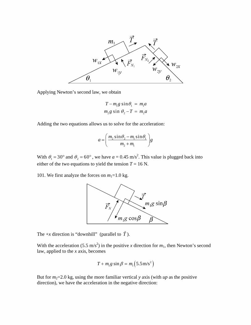
Applying Newton’s second law, we obtain
1 1
2 2
sinsin
T m g m am g T m a
1
2
θθ
− =− =
Adding the two equations allows us to solve for the acceleration:
2 2 1 1
2 1
sin sinm ma gm mθ θ⎛ ⎞−
= ⎜ ⎟+⎝ ⎠
With 1 30θ = ° and 2 60θ = ° , we have a = 0.45 m/s2. This value is plugged back into either of the two equations to yield the tension T = 16 N. 101. We first analyze the forces on m1=1.0 kg.
The +x direction is “downhill” (parallel to T ). With the acceleration (5.5 m/s2) in the positive x direction for m1, then Newton’s second law, applied to the x axis, becomes
( )21 1sin 5.5m/sT m g mβ+ =
But for m2=2.0 kg, using the more familiar vertical y axis (with up as the positive direction), we have the acceleration in the negative direction:

( )22 2 5.5m/sF T m g m+ − = −
where the tension comes in as an upward force (the cord can pull, not push). (a) From the equation for m2, with F = 6.0 N, we find the tension T = 2.6 N. (b) From the equation for m, using the result from part (a), we obtain the angle β = 17° .

Chapter 6 – Student Solutions Manual 1. We do not consider the possibility that the bureau might tip, and treat this as a purely horizontal motion problem (with the person’s push F in the +x direction). Applying Newton’s second law to the x and y axes, we obtain
, max
0s
N
F f mF mg
a− =− =
respectively. The second equation yields the normal force FN = mg, whereupon the maximum static friction is found to be (from Eq. 6-1) f s s,max mg= μ . Thus, the first equation becomes
F mg mas− = =μ 0 where we have set a = 0 to be consistent with the fact that the static friction is still (just barely) able to prevent the bureau from moving. (a) With μ s = 0 45. and m = 45 kg, the equation above leads to F = 198 N. To bring the bureau into a state of motion, the person should push with any force greater than this value. Rounding to two significant figures, we can therefore say the minimum required push is F = 2.0 × 10² N. (b) Replacing m = 45 kg with m = 28 kg, the reasoning above leads to roughly
. 21.2 10 NF = × 3. We denote as the horizontal force of the person exerted on the crate (in the +x direction), is the force of kinetic friction (in the –x direction), is the vertical normal force exerted by the floor (in the +y direction), and
Ff k NF
mg is the force of gravity. The magnitude of the force of friction is given by fk = μkFN (Eq. 6-2). Applying Newton’s second law to the x and y axes, we obtain
0k
N
F f maF mg
− =− =
respectively. (a) The second equation yields the normal force FN = mg, so that the friction is
( )( ) 2 20.35 55 kg (9.8 m/s ) 1.9 10 N .k kf mgμ= = = × (b) The first equation becomes
F mg mk a− =μ
which (with F = 220 N) we solve to find
a Fm
gk= − =μ 0 56 2. .m / s
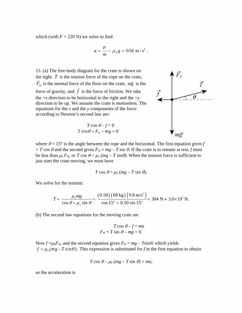
13. (a) The free-body diagram for the crate is shown on the right. T is the tension force of the rope on the crate,
is the normal force of the floor on the crate, mgNF is the
force of gravity, and is the force of friction. We take the +x direction to be horizontal to the right and the +y direction to be up. We assume the crate is motionless. The equations for the x and the y components of the force according to Newton’s second law are:
f
T cos θ – f = 0
sin 0NT F mgθ + − = where θ = 15° is the angle between the rope and the horizontal. The first equation gives f = T cos θ and the second gives FN = mg – T sin θ. If the crate is to remain at rest, f must be less than μs FN, or T cos θ < μs (mg – T sinθ). When the tension force is sufficient to just start the crate moving, we must have
T cos θ = μs (mg – T sin θ). We solve for the tension:
( ) ( ) ( )22
0.50 68 kg 9.8 m/s304 N 3.0 10 N.
cos sin cos 15 0.50 sin 15s
s
mgT μθ μ θ
= = = ≈+ ° + °
×
)
(b) The second law equations for the moving crate are
T cos θ – f = ma FN + T sin θ – mg = 0.
Now f =μkFN, and the second equation gives FN = mg – Tsinθ, which yields
( sinkf mg Tμ θ= − . This expression is substituted for f in the first equation to obtain
T cos θ – μk (mg – T sin θ) = ma, so the acceleration is

( )cos sinkk
Ta g
mθ μ θ
μ+
= − .
Numerically, it is given by
a =° + °
− =304 15 0 35 15
680 35 9 8 13
Nkg
m / s m / s2 2b gb g b gc hcos . sin. . . .
23. The free-body diagrams for block B and for the knot just above block A are shown next. is the tension force of the rope pulling on block B or pulling on the knot (as the case may be), is the tension force exerted by the second rope (at angle θ = 30°) on the knot, is the force of static friction exerted by the horizontal surface on block B, is normal force exerted by the surface on block B, W
T1
T2
f NFA is the weight of block A (WA is the
magnitude of ), and Wm gA B is the weight of block B (WB BB = 711 N is the magnitude of ). m gB
For each object we take +x horizontally rightward and +y upward. Applying Newton’s second law in the x and y directions for block B and then doing the same for the knot results in four equations:
1 ,max
2 1
2
00
cos 0sin 0
s
N B
A
T fF W
T TT W
θθ
− =− =
− =− =
where we assume the static friction to be at its maximum value (permitting us to use Eq. 6-1). Solving these equations with μs = 0.25, we obtain . 2103 N 1.0 10 NAW = ≈ × 27. The free-body diagrams for the two blocks are shown next. T is the magnitude of the tension force of the string, is the normal force on block A (the leading block), NAF NBF is the normal force on block B, is kinetic friction force on block A, f A f B is kinetic friction force on block B. Also, mA is the mass of block A (where mA = WA/g and WA = 3.6 N), and

mB is the mass of block B (where mB BB = WB/g and WB BB = 7.2 N). The angle of the incline is θ = 30°.
For each block we take +x downhill (which is toward the lower-left in these diagrams) and +y in the direction of the normal force. Applying Newton’s second law to the x and y directions of both blocks A and B, we arrive at four equations:
sin cos 0
sin cos 0
A A
NA A
B B
NB B
W f T mF W
W f T mF W
A
B
a
a
θθ
θθ
− − =− =
− + =− =
which, when combined with Eq. 6-2 ( A kA NAf Fμ= where μk A = 0.10 and B kB NBf Fμ= fB where μ
B
k B = 0.20), fully describe the dynamics of the system so long as the blocks have the same acceleration and T > 0. (a) From these equations, we find the acceleration to be
2sin cos 3.5 m/s .k A A k B B
A B
W Wa gW W
μ μθ θ⎛ ⎞⎛ ⎞+
= − =⎜ ⎟⎜ ⎟⎜ ⎟+⎝ ⎠⎝ ⎠
(b) We solve the above equations for the tension and obtain
( )cos 0.21 N.A Bk B k A
A B
W WTW W
μ μ θ⎛ ⎞
= − =⎜ ⎟+⎝ ⎠
Simply returning the value for a found in part (a) into one of the above equations is certainly fine, and probably easier than solving for T algebraically as we have done, but the algebraic form does illustrate the μk B – μk A factor which aids in the understanding of the next part. 35. We denote the magnitude of the frictional force αv , where α = ⋅70 N s m . We take the direction of the boat’s motion to be positive. Newton’s second law gives

− =αv m dvdt
.
Thus,
0 0
v t
v
dv dtv m
α= −∫ ∫
where v0 is the velocity at time zero and v is the velocity at time t. The integrals are evaluated with the result
0
ln v tv m
α⎛ ⎞= −⎜ ⎟
⎝ ⎠
We take v = v0/2 and solve for time:
1000 kgln 2 ln 2 9.9 s .70 N s/m
mtα
= = =⋅
59. The free-body diagram for the ball is shown below. Tu is the tension exerted by the upper string on the ball, is the tension force of the lower string, and m is the mass of the ball. Note that the tension in the upper string is greater than the tension in the lower string. It must balance the downward pull of gravity and the force of the lower string.
T
(a) We take the +x direction to be leftward (toward the center of the circular orbit) and +y upward. Since the magnitude of the acceleration is a = v2/R, the x component of Newton’s second law is
T T mvRu cos cos ,θ θ+ =
2
where v is the speed of the ball and R is the radius of its orbit. The y component is
T T mgu sin sin .θ θ− − = 0 The second equation gives the tension in the lower string: T T mgu= − / sinθ . Since the triangle is equilateral θ = 30.0°. Thus
2(1.34 kg)(9.80 m/s )35.0 N 8.74 N.
sin 30.0T = − =
°
(b) The net force has magnitude
( )net,str cos (35.0 N 8.74 N)cos30.0 37.9 N.uF T T θ= + = + ° = (c) The radius of the path is
R = ((1.70 m)/2)tan 30.0° = 1.47 m. Using Fnet,str = mv2/R, we find that the speed of the ball is
net,str (1.47 m)(37.9 N) 6.45 m/s.1.34 kg
RFv
m= = =
(d) The direction of is leftward (“radially inward’’). net,strF 65. (a) Using sF mgμ= , the coefficient of static friction for the surface between the two blocks is sμ = (12 N)/(39.2 N) = 0.31, where mt g = (4.0 kg)(9.8 m/s2)=39.2 N is the weight of the top block. Let be the total system mass, then the maximum horizontal force has a magnitude Ma = Mμ
9.0 kgt bM m m= + =
s g = 27 N. (b) The acceleration (in the maximal case) is a = μsg =3.0 m/s2. 77. The magnitude of the acceleration of the cyclist as it moves along the horizontal circular path is given by v2/R, where v is the speed of the cyclist and R is the radius of the curve. (a) The horizontal component of Newton’s second law is f = mv2/R, where f is the static friction exerted horizontally by the ground on the tires. Thus,
( )( )285.0 kg 9.00 m/s275 N.
25.0 mf = =
(b) If FN is the vertical force of the ground on the bicycle and m is the mass of the bicycle and rider, the vertical component of Newton’s second law leads to FN = mg = 833 N. The magnitude of the force exerted by the ground on the bicycle is therefore
2 2 2 2(275 N) (833 N) 877 N.Nf F+ = + = 81. (a) If we choose “downhill” positive, then Newton’s law gives
mA g sinθ – fA – T = mA a for block A (where θ = 30º). For block B we choose leftward as the positive direction and write T – fB = mB B a. Now
fA = μk,incline FNA = μ′mA g cosθ using Eq. 6-12 applies to block A, and
fB = μk FNB = μB k mB g. In this particular problem, we are asked to set μ′ = 0, and the resulting equations can be straightforwardly solved for the tension: T = 13 N. (b) Similarly, finding the value of a is straightforward:
a = g(mA sinθ – μk mB )/(mA + mB) =1.6 m/s . B
2
85. The mass of the car is m = (10700/9.80) kg = 1.09 × 10³ kg. We choose “inward” (horizontally towards the center of the circular path) as the positive direction. (a) With v = 13.4 m/s and R = 61 m, Newton’s second law (using Eq. 6-18) leads to
f mvRs = = ×
23321 10. N .
(b) Noting that FN = mg in this situation, the maximum possible static friction is found to be
( )( ) 3,max 0.35 10700 N 3.75 10 Ns sf mgμ= = = ×
using Eq. 6-1. We see that the static friction found in part (a) is less than this, so the car rolls (no skidding) and successfully negotiates the curve. 91. We apply Newton’s second law (as Fpush – f = ma). If we find Fpush < fmax, we conclude “no, the cabinet does not move” (which means a is actually 0 and f = Fpush), and
if we obtain a > 0 then it is moves (so f = fk). For fmax and fk we use Eq. 6-1 and Eq. 6-2 (respectively), and in those formulas we set the magnitude of the normal force equal to 556 N. Thus, fmax = 378 N and fk = 311 N. (a) Here we find Fpush < fmax which leads to f = Fpush = 222 N. (b) Again we find Fpush < fmax which leads to f = Fpush = 334 N. (c) Now we have Fpush > fmax which means it moves and f = fk = 311 N. (d) Again we have Fpush > fmax which means it moves and f = fk = 311 N. (e) The cabinet moves in (c) and (d). 99. Replace fs with fk in Fig. 6-5(b) to produce the appropriate force diagram for the first part of this problem (when it is sliding downhill with zero acceleration). This amounts to replacing the static coefficient with the kinetic coefficient in Eq. 6-13: μk = tanθ. Now (for the second part of the problem, with the block projected uphill) the friction direction is reversed from what is shown in Fig. 6-5(b). Newton’s second law for the uphill motion (and Eq. 6-12) leads to
– m g sinθ – μk m g cosθ = m a. Canceling the mass and substituting what we found earlier for the coefficient, we have
– g sinθ – tanθ g cosθ = a . This simplifies to – 2 g sinθ = a. Eq. 2-16 then gives the distance to stop: Δx = –vo
2/2a. (a) Thus, the distance up the incline traveled by the block is Δx = vo
2/(4gsinθ ). (b) We usually expect μs > μk (see the discussion in section 6-1). Sample Problem 6-2 treats the “angle of repose” (the minimum angle necessary for a stationary block to start sliding downhill): μs = tan(θrepose). Therefore, we expect θrepose > θ found in part (a). Consequently, when the block comes to rest, the incline is not steep enough to cause it to start slipping down the incline again. 105. Probably the most appropriate picture in the textbook to represent the situation in this problem is in the previous chapter: Fig. 5-9. We adopt the familiar axes with +x rightward and +y upward, and refer to the 85 N horizontal push of the worker as P (and assume it to be rightward). Applying Newton’s second law to the x axis and y axis, respectively, produces
0.k
N
P f maF mg
− =− =

Using we find a = 0.36 m/sv v a202 2= + Δx 2. Consequently, we obtain fk = 71 N and FN =
392 N. Therefore, μk = fk/ FN = 0.18.
Chapter 7 – Student Solutions Manual 3. (a) From Table 2-1, we have v v . Thus, a2
02 2= + Δx
( ) ( )( )22 7 15 2
0 2 2.4 10 m/s 2 3.6 10 m/s 0.035 m 2.9 10 m/s.v v a x= + Δ = × + × = × 7
(b) The initial kinetic energy is
( ) ( )22 27 70
1 1 1.67 10 kg 2.4 10 m/s 4.8 10 J.2 2iK mv − −= = × × = × 13
The final kinetic energy is
( ) ( )22 27 71 1 1.67 10 kg 2.9 10 m/s 6.9 10 J.2 2fK mv − −= = × × = × 13
The change in kinetic energy is ΔK = 6.9 × 10⁻¹³ J – 4.8 × 10⁻¹³ J = 2.1 × 10⁻¹³ J. 17. (a) We use to denote the upward force exerted by the cable on the astronaut. The force of the cable is upward and the force of gravity is mg downward. Furthermore, the acceleration of the astronaut is g/10 upward. According to Newton’s second law, F – mg = mg/10, so F = 11 mg/10. Since the force
F
F and the displacement d are in the same direction, the work done by is F
2411 11 (72 kg)(9.8 m/s )(15 m) 1.164 10 J
10 10FmgdW Fd= = = = ×
which (with respect to significant figures) should be quoted as 1.2 × 10⁴ J. (b) The force of gravity has magnitude mg and is opposite in direction to the displacement. Thus, using Eq. 7-7, the work done by gravity is
2 4 (72 kg)(9.8 m/s )(15 m) 1.058 10 JgW mgd= − = − = − × which should be quoted as – 1.1 × 10⁴ J. (c) The total work done is W . Since the astronaut started from rest, the work-kinetic energy theorem tells us that this (which we round to 1 ) is her final kinetic energy.
= × − × = ×1164. 10 J 1.058 10 J 1.06 10 J4 4 3
1. ×10 J3
(d) Since K mv= 1
22 , her final speed is

v Km
= =×
=2 2 106 10 54
3( . .J)72 kg
m / s.
19. (a) We use F to denote the magnitude of the force of the cord on the block. This force is upward, opposite to the force of gravity (which has magnitude Mg). The acceleration is
downward. Taking the downward direction to be positive, then Newton’s second law yields a g= / 4
F ma Mg F M gnet = ⇒ − = F
HGIKJ4
so F = 3Mg/4. The displacement is downward, so the work done by the cord’s force is, using Eq. 7-7,
WF = –Fd = –3Mgd/4.
(b) The force of gravity is in the same direction as the displacement, so it does work . gW Mgd=
(c) The total work done on the block is − + =3 4M gd M gd M gd 4 . Since the block starts from rest, we use Eq. 7-15 to conclude that this M gd 4b g is the block’s kinetic energy K at the moment it has descended the distance d. (d) Since 21
2 ,K Mv= the speed is
v KM
MgdM
gd= = =
2 2 42
( / )
at the moment the block has descended the distance d. 29. (a) As the body moves along the x axis from xi = 3.0 m to xf = 4.0 m the work done by the force is
2 2 2 2 6 3( ) 3 (4.0 3.0 ) 21 J.f f
i i
x x
x f ix xW F dx x dx x x= = − = − − = − − = −∫ ∫
According to the work-kinetic energy theorem, this gives the change in the kinetic energy:
W K m v vf i= = −Δ12
2 2d i where vi is the initial velocity (at xi) and vf is the final velocity (at xf). The theorem yields
2 22 2( 21 J) (8.0 m/s) 6.6 m/s.2.0 kgf i
Wv vm
−= + = + =
(b) The velocity of the particle is vf = 5.0 m/s when it is at x = xf. The work-kinetic energy theorem is used to solve for xf. The net work done on the particle is ( )2 23 f iW x x= − − , so the theorem leads to
− − = −3 12
2 2 2 2x x m v vf i f id i d .i Thus,
( ) ( )2 2 2 2 2 22.0 kg (5.0 m/s) (8.0 m/s) (3.0 m) 4.7 m.6 6 N/mf f i imx v v x= − − + = − − + =
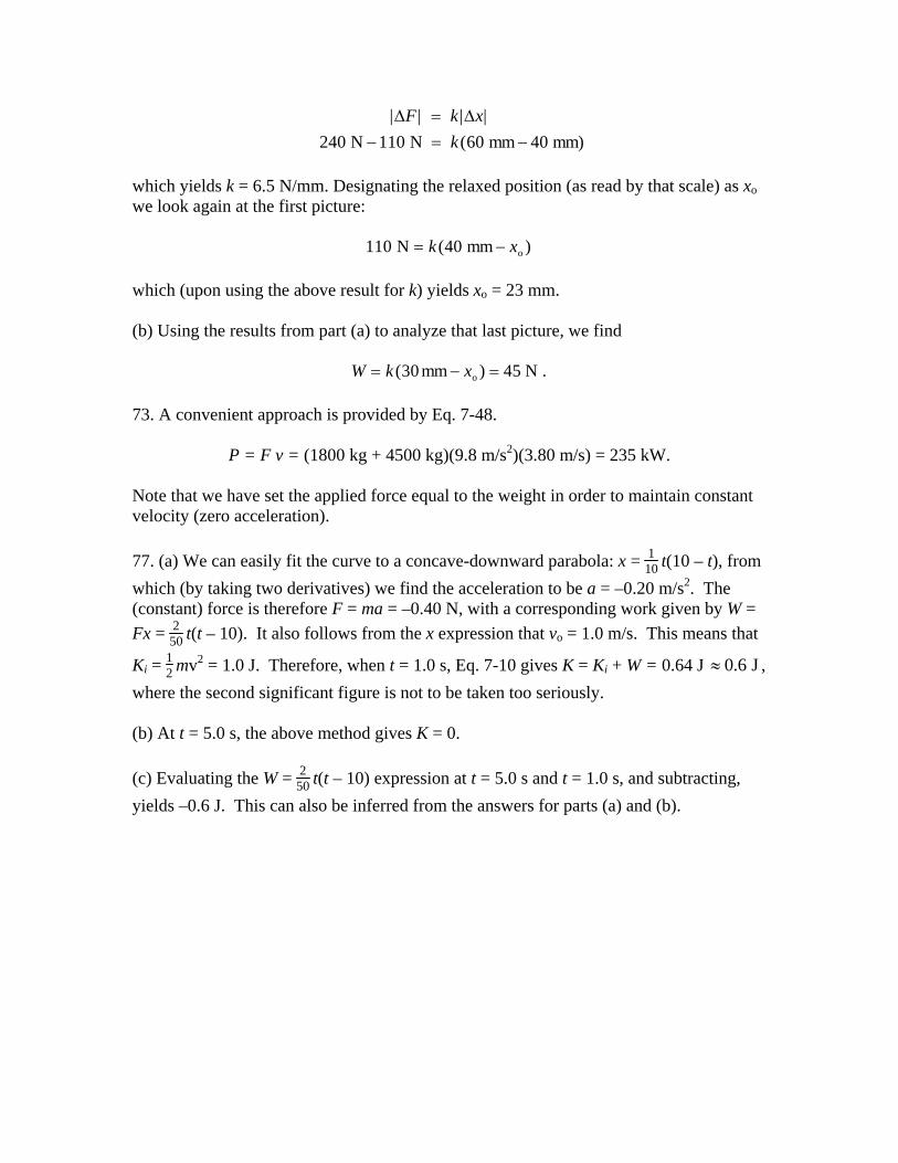
35. (a) The graph shows F as a function of x assuming x0 is positive. The work is negative as the object moves from x x= x=0 0 to and positive as it moves from . x x x x= =0 02 to Since the area of a triangle is (base)(altitude)/2, the work done from is x x= =0 0 to x 0 0( )( ) / 2x F− and the work done from is x x x x= =0 02 to
0 0 0(2 )( ) / 2x x F− = 0 0( )( ) / 2x F The total work is the sum, which is zero. (b) The integral for the work is
022
0 00 0 0
1 0.2
xx xdx F xx x
⎛ ⎞ ⎛ ⎞= − =⎜ ⎟ ⎜ ⎟
⎝ ⎠ ⎝ ⎠
02
0
xW F= −∫
43. The power associated with force F is given by P F v = ⋅ , where v is the velocity of the object on which the force acts. Thus,
2cos (122 N)(5.0 m/s)cos37 4.9 10 W. P F v Fv φ= ⋅ = = ° = × 45. (a) The power is given by P = Fv and the work done by F from time to time t is given by
t1 2
W P t Fv
t
t
t
t d d= = tzz .
1
2
1
2
Since is the net force, the magnitude of the acceleration is a = F/m, and, since the initial velocity is , the velocity as a function of time is given by
Fv0 0=
v v at F m t= + =0 ( ) . Thus
2
1
2 22 1
1( / ) d ( / )( )2
t
tW F m t t F m t t= =∫ 2 2 .−
For and t1 0= 2 1.0s,t =
221 (5.0 N) (1.0 s) = 0.83 J.
2 15 kgW
⎛ ⎞= ⎜ ⎟
⎝ ⎠
(b) For and 1 1.0s,t = 2 2.0s,t =
22 21 (5.0 N) [(2.0 s) (1.0 s) ] 2.5 J.
2 15 kgW
⎛ ⎞= −⎜ ⎟
⎝ ⎠=
(c) For and 1 2.0st = 2 3.0s,t =
22 21 (5.0 N) [(3.0 s) (2.0 s) ] 4.2 J.
2 15 kgW
⎛ ⎞= −⎜ ⎟
⎝ ⎠=
(d) Substituting v = (F/m)t into P = Fv we obtain P F t m= 2 for the power at any time t. At the end of the third second
P (5.0 N) (3.0 s)15 kg
5.0 W.2
=FHG
IKJ =
47. The total work is the sum of the work done by gravity on the elevator, the work done by gravity on the counterweight, and the work done by the motor on the system:
WT = We + Wc + Ws. Since the elevator moves at constant velocity, its kinetic energy does not change and according to the work-kinetic energy theorem the total work done is zero. This means We + Wc + Ws = 0. The elevator moves upward through 54 m, so the work done by gravity on it is
2 5(1200 kg)(9.80 m/s )(54 m) 6.35 10 J.e eW m gd= − = − = − × The counterweight moves downward the same distance, so the work done by gravity on it is
2 5(950 kg)(9.80 m/s )(54 m) 5.03 10 J.c cW m gd= = = × Since WT = 0, the work done by the motor on the system is
5 56.35 10 J 5.03 10 J 1.32 10 J.s e cW W W= − − = × − × = × 5 This work is done in a time interval of Δt 3.0 min 180 s,= = so the power supplied by the motor to lift the elevator is
521.32 10 J 7.4 10 W.
180 ssWPt
×= = = ×
Δ
63. (a) In 10 min the cart moves
mi 5280 ft/mi6.0 (10 min) fth 60 min/h
d ⎛ ⎞⎛ ⎞= =⎜ ⎟⎜ ⎟⎝ ⎠⎝ ⎠
5280
⋅
so that Eq. 7-7 yields
5cos (40 lb)(5280 ft) cos 30 1.8 10 ft lb.W Fd φ= = ° = × (b) The average power is given by Eq. 7-42, and the conversion to horsepower (hp) can be found on the inside back cover. We note that 10 min is equivalent to 600 s.
5
avg1.8 10 ft lb 305 ft lb/s
600 sP × ⋅
= = ⋅
which (upon dividing by 550) converts to Pavg = 0.55 hp. 69. (a) Eq. 7-6 gives Wa = Fd = (209 N)(1.50 m) ≈ 314 J. (b) Eq. 7-12 leads to Wg = (25.0 kg)(9.80 m/s2)(1.50 m)cos(115º) ≈ –155 J. (c) The angle between the normal force and the direction of motion remains 90º at all times, so the work it does is zero. (d) The total work done on the crate is WT = 314 J – 155 J =158 J. 71. (a) Hooke’s law and the work done by a spring is discussed in the chapter. Taking absolute values, and writing that law in terms of differences Δ ΔF and x , we analyze the first two pictures as follows:
N N mm 40 mm)
| | | |(
Δ ΔF k xk
=− = −240 110 60
which yields k = 6.5 N/mm. Designating the relaxed position (as read by that scale) as xo we look again at the first picture:
110 40 N mm o= −k x( ) which (upon using the above result for k) yields xo = 23 mm. (b) Using the results from part (a) to analyze that last picture, we find
W k x= − =( )30 45mm N .o 73. A convenient approach is provided by Eq. 7-48.
P = F v = (1800 kg + 4500 kg)(9.8 m/s2)(3.80 m/s) = 235 kW. Note that we have set the applied force equal to the weight in order to maintain constant velocity (zero acceleration). 77. (a) We can easily fit the curve to a concave-downward parabola: x = 1
10 t(10 – t), from which (by taking two derivatives) we find the acceleration to be a = –0.20 m/s2. The (constant) force is therefore F = ma = –0.40 N, with a corresponding work given by W = Fx = 2
50 t(t – 10). It also follows from the x expression that vo = 1.0 m/s. This means that
Ki = 12 mv2 = 1.0 J. Therefore, when t = 1.0 s, Eq. 7-10 gives K = Ki + W = 0.64 J , where the second significant figure is not to be taken too seriously.
0.6 J≈
(b) At t = 5.0 s, the above method gives K = 0. (c) Evaluating the W = 2
50 t(t – 10) expression at t = 5.0 s and t = 1.0 s, and subtracting, yields –0.6 J. This can also be inferred from the answers for parts (a) and (b).

Chapter 8 – Student Solutions Manual 5. The potential energy stored by the spring is given by U kx= 1
22 , where k is the spring
constant and x is the displacement of the end of the spring from its position when the spring is in equilibrium. Thus
k Ux
= = = ×2 2 25
0 0758 9 102 2
3Jm
N mb gb g.
. .
9. We neglect any work done by friction. We work with SI units, so the speed is converted: v = 130(1000/3600) = 36.1 m/s. (a) We use Eq. 8-17: Kf + Uf = Ki + Ui with Ui = 0, Uf = mgh and Kf = 0. Since K mvi = 1
22 , where v is the initial speed of the truck, we obtain
2 2
22
1 (36.1 m/s) 66.5 m2 2 2(9.8 m/s )
vmv mgh hg
= ⇒ = = = .
If L is the length of the ramp, then L sin 15° = 66.5 m so that L = 66.5/sin 15° = 257 m. Therefore, the ramp must be about 2.6× 10² m long if friction is negligible. (b) The answers do not depend on the mass of the truck. They remain the same if the mass is reduced. (c) If the speed is decreased, h and L both decrease (note that h is proportional to the square of the speed and that L is proportional to h). 11. (a) If Ki is the kinetic energy of the flake at the edge of the bowl, Kf is its kinetic energy at the bottom, Ui is the gravitational potential energy of the flake-Earth system with the flake at the top, and Uf is the gravitational potential energy with it at the bottom, then Kf + Uf = Ki + Ui. Taking the potential energy to be zero at the bottom of the bowl, then the potential energy at the top is Ui = mgr where r = 0.220 m is the radius of the bowl and m is the mass of the flake. Ki = 0 since the flake starts from rest. Since the problem asks for the speed at the
bottom, we write 12
2mv for Kf. Energy conservation leads to
W F d mgh mgLg g= ⋅ = = −( cos )1 θ .
The speed is 2 2.08 mv gr= = /s .

(b) Since the expression for speed does not contain the mass of the flake, the speed would be the same, 2.08 m/s, regardless of the mass of the flake. (c) The final kinetic energy is given by Kf = Ki + Ui – Uf. Since Ki is greater than before, Kf is greater. This means the final speed of the flake is greater. 31. We refer to its starting point as A, the point where it first comes into contact with the spring as B, and the point where the spring is compressed |x| = 0.055 m as C. Point C is our reference point for computing gravitational potential energy. Elastic potential energy (of the spring) is zero when the spring is relaxed. Information given in the second sentence allows us to compute the spring constant. From Hooke's law, we find
k Fx
= = = ×270 N0.02 m
1.35 10 N m4 .
(a) The distance between points A and B is Fg and we note that the total sliding distance
+ x is related to the initial height h of the block (measured relative to C) by
hx+
= sin θ
where the incline angle θ is 30°. Mechanical energy conservation leads to
K U K U
mgh kx
A A C C+ = +
+ = + 0 12
0 2
which yields
h kxmg
= =×
=2 2
22 2 12 9 8
1.35 10 N m 0.055 m
kg m s0.174 m
4c hb gb g c h.
.
Therefore,
+ =°
=°
=x hsin 30
0.174 msin30
0.35 m .
(b) From this result, we find = − =0.35 0.055 0.29 m , which means that Δy = − = −sin mθ 015. in sliding from point A to point B. Thus, Eq. 8-18 gives
012
0
Δ Δ
Δ
K U
mv mg hB
+ =
+ =2
which yields v g hB = − = − − =2 9 8 015Δ . .b gb g 1.7 m s . 45. (a) The work done on the block by the force in the rope is, using Eq. 7-7,
cos (7.68 N)(4.06 m) cos15.0 30.1J.W Fd θ= = ° = (b) Using f for the magnitude of the kinetic friction force, Eq. 8-29 reveals that the increase in thermal energy is
th (7.42 N)(4.06 m) 30.1J.E fdΔ = = = (c) We can use Newton's second law of motion to obtain the frictional and normal forces, then use μk = f/FN to obtain the coefficient of friction. Place the x axis along the path of the block and the y axis normal to the floor. The x and the y component of Newton's second law are
x: F cos θ – f = 0 y: FN + F sin θ – mg = 0,
where m is the mass of the block, F is the force exerted by the rope, and θ is the angle between that force and the horizontal. The first equation gives
f = F cos θ = (7.68 N) = 7.42 N cos15.0° and the second gives
FN = mg – F sin θ = (3.57 kg)(9.8 m/s2) – (7.68 N)sin = 33.0 N. 15.0° Thus,
7.42 N 0.22533.0 Nk
N
fF
μ = = = .
47. (a) We take the initial gravitational potential energy to be Ui = 0. Then the final gravitational potential energy is Uf = –mgL, where L is the length of the tree. The change is
U U mgLf i− = − = − = − ×( ( .25 12 2 9 103 kg) 9.8 m s m) J .2d i
(b) The kinetic energy is 2 21 1 (25 kg)(5.6 m/s) 3.9 10 J2 2
K mv= = = × 2 .
(c) The changes in the mechanical and thermal energies must sum to zero. The change in thermal energy is ΔEth = fL, where f is the magnitude of the average frictional force; therefore,
2 3
23.9 10 J 2.9 10 J 2.1 10 N12 m
K UfL
Δ + Δ × − ×= − = − = ×
69. There is the same potential energy change in both circumstances, so we can equate the kinetic energy changes as well:
ΔK2 = ΔK1 ⇒ 12 m vB
2 – 12 m(4.00)2 =
12 m(2.60)2 –
12 m(2.00)2
which leads to vB = 4.33 m/s. B
75. We note that if the larger mass (block B, mB = 2 kg) falls d = 0.25 m, then the smaller mass (blocks A, mA = 1 kg) must increase its height by sin 30h d= ° . Thus, by mechanical energy conservation, the kinetic energy of the system is total 3.7 JB AK m gd m gh= − = . 83. The initial height shown in the figure is the y = 0 level in our computations of Ug, and in parts (a) and (b) the heights are ya = 0.80 sin 40° = 0.51 m and yb = 1.00 sin 40° = 0.64 m, respectively. (a) The conservation of energy, Eq. 8-17, leads to
Ki + Ui = Ka + Ua ⇒ 16 + 0 = Ka + mgya + 12k(0.20)2
from which we obtain Ka = 16 – 5.0 – 4.0 = 7.0 J. (b) Again we use the conservation of energy
Ki + Ui = Kb + Ub ⇒ Ki + 0 = 0 + mgyb + 12 k(0.40)2
from which we obtain Ki = 6.0 + 16 = 22 J. 87. Since the speed is constant ΔK = 0 and Eq. 8-33 (an application of the energy conservation concept) implies
W E E Eapplied th th cube th floor= = +Δ Δ Δb g b g . Thus, if Wapplied = (15)(3.0) = 45 J, and we are told that ΔEth (cube) = 20 J, then we conclude that ΔEth (floor) = 25 J. 109. The connection between angle θ (measured from vertical) and height h (measured from the lowest point, which is our choice of reference position in computing the

gravitational potential energy mgh) is given by h = L(1 – cos θ ) where L is the length of the pendulum. (a) Using this formula (or simply using intuition) we see the initial height is h1 = 2L, and of course h2 = 0. We use energy conservation in the form of Eq. 8-17.
(2
K U K U
mg L mv
1 1 2 2
20 12
0
+ = +
+ =) +
This leads tov g= 2 L . With L = 0.62 m, we have
22 (9.8 m/s )(0.62 m) 4.9 m/sv = = . (b) The ball is in circular motion with the center of the circle above it, so a v r= 2 / upward, where r = L. Newton's second law leads to
T mg m vr
T m g gLL
mg− = ⇒ = +FHGIKJ =
2 4 5 .
With m = 0.092 kg, the tension is given by T = 4.5 N. (c) The pendulum is now started (with zero speed) at 90iθ = ° (that is, hi = L), and we look for an angle θ such that T = mg. When the ball is moving through a point at angle θ, then Newton's second law applied to the axis along the rod yields
T mg m vr
− =cosθ2
which (since r = L) implies v2 = gL(1 – cos θ ) at the position we are looking for. Energy conservation leads to
(1
K U K U
mgL mv mgL
gL gL gL
i i+ = +
+ = + −
= − + −
0 12
1
12
1
2 ( cos )
( ( cos )) cos )
θ
θ θ
where we have divided by mass in the last step. Simplifying, we obtain
1 1cos 713
θ − ⎛ ⎞= = °⎜ ⎟⎝ ⎠
.
(d) Since the angle found in (c) is independent of the mass, the result remains the same if the mass of the ball is changed. 111. (a) At the top of its flight, the vertical component of the velocity vanishes, and the horizontal component (neglecting air friction) is the same as it was when it was thrown. Thus,
K mvxtop kg m s= =12
12
0 050 8 0 302 2. . cosb g b gc h° = 1.2 J.
(b) We choose the point 3.0 m below the window as the reference level for computing the potential energy. Thus, equating the mechanical energy when it was thrown to when it is at this reference level, we have (with SI units understood)
mgy K K
m m
0 0
2 29 8 3 0 12
8 0 12
mv
+ =
+ =. . .b gb g b g
which yields (after canceling m and simplifying) v = 11 m/s. (c) As mentioned, m cancels — and is therefore not relevant to that computation. (d) The v in the kinetic energy formula is the magnitude of the velocity vector; it does not depend on the direction. 119. (a) During the final d = 12 m of motion, we use
1 1 2 2
21 0 0 02
k
k
K U K U f d
mv f d
+ = + +
+ = + +
where v = 4.2 m/s. This gives fk = 0.31 N. Therefore, the thermal energy change is
3.7 J.kf d = (b) Using fk = 0.31 N we obtain fkdtotal = 4.3 J for the thermal energy generated by friction; here, dtotal = 14 m. (c) During the initial d' = 2 m of motion, we have
K U W K U f d W mv f dk k0 0 1 120 0 1
20+ + = + + ′ ⇒ + + = + + ′app app
which essentially combines Eq. 8-31 and Eq. 8-33. This leads to the result Wapp = 4.3 J, and — reasonably enough — is the same as our answer in part (b).

121. We use Eq. 8-20. (a) The force at x = 2.0 m is
(17.5) ( 2.8) 4.9 N.4.0 1.0
dUFdx
− − −= − ≈ − =
−
(b) The force points in the +x direction (but there is some uncertainty in reading the graph which makes the last digit not very significant). (c) The total mechanical energy at x = 2.0 m is
E mv U= + ≈ − − = −12
12
2 0 15 7 7 552 2( . )( . ) . .
in SI units (Joules). Again, there is some uncertainty in reading the graph which makes the last digit not very significant. At that level (–5.5 J) on the graph, we find two points where the potential energy curve has that value — at x ≈ 1.5 m and x ≈ 13.5 m. Therefore, the particle remains in the region 1.5 < x < 13.5 m. The left boundary is at x = 1.5 m. (d) From the above results, the right boundary is at x = 13.5 m. (e) At x = 7.0 m, we read U ≈ –17.5 J. Thus, if its total energy (calculated in the previous part) is E ≈ –5.5 J, then we find
12
12 2 352mv E U vm
E U= − ≈ ⇒ = − ≈ J ( ) . m s
where there is certainly room for disagreement on that last digit for the reasons cited above. 123. Converting to SI units, v0 8 3= . m s and v = 111. m s . The incline angle is 5.0θ = ° . The height difference between the car's highest and lowest points is (50 m) sin θ = 4.4 m. We take the lowest point (the car's final reported location) to correspond to the y = 0 reference level. (a) Using Eq. 8-31 and Eq. 8-33, we find
f d K U f d m v v mgyk k= − − ⇒ = − +Δ Δ12 0
2 20c h .
Therefore, the mechanical energy reduction (due to friction) is fk d = 2.4 × 10⁴ J. (b) With d = 50 m, we solve for fk and obtain 4.7 × 10² N.

127. (a) When there is no change in potential energy, Eq. 8-24 leads to
W K m v vapp = = −Δ12
202c h .
Therefore, . ΔE = ×6 0 103. J (b) From the above manipulation, we see Wapp = 6.0 × 10³ J. Also, from Chapter 2, we know that Δ Δt v a= = 10 s . Thus, using Eq. 7-42,
P Wtavg W .= =
×=
Δ6 0 10
10600
3.
(c) and (d) The constant applied force is ma = 30 N and clearly in the direction of motion, so Eq. 7-48 provides the results for instantaneous power
P F vvv
= ⋅ ===
RST300 10900 30
W for m sW for m s
We note that the average of these two values agrees with the result in part (b). 131. The power generation (assumed constant, so average power is the same as instantaneous power) is
3 3 3 28(3 / 4)(1200m )(10 kg / m )(9.8m / s )(100m) 8.80 10 W.
1.0smghP
t= = = ×
133. (a) Sample Problem 8-3 illustrates simple energy conservation in a similar situation, and derives the frequently encountered relationship: v = 2gh . In our present problem, the height change is equal to the rod length L. Thus, using the suggested notation for the speed, we have vo = 2gL . (b) At B the speed is (from Eq. 8-17)
20 2 4v v gL g= + = L .
The direction of the centripetal acceleration (v2/r = 4gL/L = 4g) is upward (at that moment), as is the tension force. Thus, Newton’s second law gives
T – mg = m(4g) ⇒ T = 5mg.

(c) The difference in height between C and D is L, so the “loss” of mechanical energy (which goes into thermal energy) is –mgL. (d) The difference in height between B and D is 2L, so the total “loss” of mechanical energy (which all goes into thermal energy) is –2mgL.

Chapter 9 – Student Solutions Manual 15. We need to find the coordinates of the point where the shell explodes and the velocity of the fragment that does not fall straight down. The coordinate origin is at the firing point, the +x axis is rightward, and the +y direction is upward. The y component of the velocity is given by v = v0 y – gt and this is zero at time t = v0 y/g = (v0/g) sin θ0, where v0 is the initial speed and θ0 is the firing angle. The coordinates of the highest point on the trajectory are
( )22
00 0 0 0 0 2
20 m/scos sin cos sin 60 cos60 17.7 m
9.8 m/sxvx v t v tg
θ θ θ= = = = ° ° =
and
y v t gt vgy= − = = =°
02 0
22
0
221
212
12
209 8
60 15 3sin.
sin .θ m / s m / s
m.2
b g
Since no horizontal forces act, the horizontal component of the momentum is conserved. Since one fragment has a velocity of zero after the explosion, the momentum of the other equals the momentum of the shell before the explosion. At the highest point the velocity of the shell is v0 cosθ0, in the positive x direction. Let M be the mass of the shell and let V0 be the velocity of the fragment. Then Mv0cosθ0 = MV0/2, since the mass of the fragment is M/2. This means
V v0 0 02 2 20 60 20= = =°cos cosθ m / s m / s.b g This information is used in the form of initial conditions for a projectile motion problem to determine where the fragment lands. Resetting our clock, we now analyze a projectile launched horizontally at time t = 0 with a speed of 20 m/s from a location having coordinates x0 = 17.7 m, y0 = 15.3 m. Its y coordinate is given by y y gt= −0
12
2 , and
when it lands this is zero. The time of landing is t y= 2 0 / g and the x coordinate of the landing point is
x x V t x V yg
= + = + = + =0 0 0 002 17 7
2 1539 8
53..
. m 20 m / s
m m / s
m.2b g b g
23. The initial direction of motion is in the +x direction. The magnitude of the average force Favg is given by
32
32.4 N s 1.20 10 N2.70 10 savg
JFt −
⋅= = = ×Δ ×
The force is in the negative direction. Using the linear momentum-impulse theorem stated in Eq. 9-31, we have
–FavgΔt = mvf – mvi.

where m is the mass, vi the initial velocity, and vf the final velocity of the ball. Thus,
( )( ) ( )( )3avg 0.40 kg 14 m s 1200 N 27 10 s
67 m s.0.40 kg
if
mv F tv
m
−− ×− Δ= = = −
(a) The final speed of the ball is | |fv = 67 m/s. (b) The negative sign indicates that the velocity is in the –x direction, which is opposite to the initial direction of travel. (c) From the above, the average magnitude of the force is . 3
avg 1.20 10 NF = × (d) The direction of the impulse on the ball is –x, same as the applied force. 35. (a) We take the force to be in the positive direction, at least for earlier times. Then the impulse is
3 3
3
3.0 10 3.0 10 6 9
0 0
3.0 106 2 9 3
0
(6.0 10 ) (2.0 10 )
1 1(6.0 10 ) (2.0 10 )2 3
9.0 N s.
J Fdt t t
t t
− −
−
× ×
×
2 dt⎡ ⎤= = × − ×⎣ ⎦
⎡ ⎤= × − ×⎢ ⎥⎣ ⎦
= ⋅
∫ ∫
(b) Since J = Favg Δt, we find
F Jtavg
3 9.0 N s3.0 10 s
3.0 10 N.Δ
=⋅
×= ×−3
(c) To find the time at which the maximum force occurs, we set the derivative of F with respect to time equal to zero – and solve for t. The result is t = 1.5 × 10⁻³ s. At that time the force is
Fmax6 96.0 10 10 2.0 10 10 4.5 10 N.= × × − × × = ×− −c hc h c hc h15 153 3 2
. . 3 (d) Since it starts from rest, the ball acquires momentum equal to the impulse from the kick. Let m be the mass of the ball and v its speed as it leaves the foot. Then,
9.0 N s 20 m/s.0.45 kg
p Jvm m
⋅= = = =

39. No external forces with horizontal components act on the man-stone system and the vertical forces sum to zero, so the total momentum of the system is conserved. Since the man and the stone are initially at rest, the total momentum is zero both before and after the stone is kicked. Let ms be the mass of the stone and vs be its velocity after it is kicked; let mm be the mass of the man and vm be his velocity after he kicks the stone. Then
msvs + mmvm = 0 → vm = –msvs/mm. We take the axis to be positive in the direction of motion of the stone. Then
( )( ) 30.068 kg 4.0 m/s3.0 10 m/s
91 kgmv −= − = − × ,
or . The negative sign indicates that the man moves in the direction opposite to the direction of motion of the stone.
3| | 3.0 10 m/mv −= × s
47. Our notation is as follows: the mass of the original body is M = 20.0 kg; its initial velocity is in SI units (m/s); the mass of one fragment is mv0 200= i 1 = 10.0 kg; its velocity is in SI units; the mass of the second fragment is mv1 100= − j 2 = 4.0 kg; its velocity is in SI units; and, the mass of the third fragment is mv2 500= − i 3 = 6.00 kg. (a) Conservation of linear momentum requires Mv m v m v m v0 1 1 2 2 3 3= + + , which (using the above information) leads to
3 33
ˆ ˆ(1.00 10 i 0.167 10 j) m/sv = × − × in SI units. The magnitude of is v3 v3
2 2 31000 167 101 10= + − = ×( ) . m / s . It points at tan–1 (–167/1000) = –9.48° (that is, at 9.5° measured clockwise from the +x axis). (b) We are asked to calculate ΔK or
12
12
12
12
3 23 101 12
2 22
3 32
02 6m v m v m v Mv+ +F
HGIKJ − = ×. J.
61. (a) Let m1 be the mass of the cart that is originally moving, v1i be its velocity before the collision, and v1f be its velocity after the collision. Let m2 be the mass of the cart that is originally at rest and v2f be its velocity after the collision. Then, according to Eq. 9-67,
v m mm m
vf i11 2
1 21=
−+ .
Using SI units (so m1 = 0.34 kg), we obtain

1 1
2 11 1
1.2 m/s 0.66 m/s (0.34 kg) 0.099 kg.1.2 m/s 0.66 m/s
i f
i f
v vm m
v v− ⎛ ⎞−
= = =⎜ ⎟+ +⎝ ⎠
(b) The velocity of the second cart is given by Eq. 9-68:
12 1
1 2
2 2(0.34 kg) (1.2 m/s) 1.9 m/s.0.34 kg 0.099 kgf i
mv vm m
⎛ ⎞= = =⎜ ⎟+ +⎝ ⎠
(c) The speed of the center of mass is
v m v m vm m
i icom m s.=
++
=+
+=1 1 2 2
1 2
0 34 12 00 34 0 099
0 93( . ) ( . ). .
.
Values for the initial velocities were used but the same result is obtained if values for the final velocities are used. 63. (a) Let m1 be the mass of the body that is originally moving, v1i be its velocity before the collision, and v1f be its velocity after the collision. Let m2 be the mass of the body that is originally at rest and v2f be its velocity after the collision. Then, according to Eq. 9-67,
v m mm m
vf i11 2
1 21=
−+
.
We solve for m2 to obtain
mv vv v
mi f
f i2
1 1
1 11=
−
+.
We combine this with to obtain v vf i1 1 4= / m m2 13 5 3 2 0 5 12= = =. .b g kg . (b) The speed of the center of mass is
v m v m vm m
i icom m s=
++
=+
=1 1 2 2
1 2
2 0 4 02 0 12
2 5. .. .
.b gb g .
77. (a) The thrust of the rocket is given by T = Rvrel where R is the rate of fuel consumption and vrel is the speed of the exhaust gas relative to the rocket. For this problem R = 480 kg/s and vrel = 3.27 × 10³ m/s, so
T = × = ×480 3 27 10 157 103 6kg s m s N .b gc h. .

(b) The mass of fuel ejected is given by Mfuel = R tΔ , where Δt is the time interval of the burn. Thus, Mfuel = (480 kg/s)(250 s) = 1.20 × 10⁵ kg. The mass of the rocket after the burn is
Mf = Mi – Mfuel = (2.55 × 10⁵ kg ) – (1.20 × 10⁵ kg) = 1.35 ×10⁵ kg. (c) Since the initial speed is zero, the final speed is given by
v v MMf
i
f
= = ×××
FHG
IKJ = ×rel
5
ln ln 2.55 10 m s327 10135 10
2 08 1035
3..
. .c h
79. (a) We consider what must happen to the coal that lands on the faster barge during one minute (Δt = 60s). In that time, a total of m = 1000 kg of coal must experience a change of velocityΔv = − = =20 10 10 2 8km h km h km h m s. , where rightwards is considered the positive direction. The rate of change in momentum for the coal is therefore
( )( )1000 kg 2.8 m/s46 N
60 sp m vt t
Δ Δ= = =
Δ Δ
which, by Eq. 9-23, must equal the force exerted by the (faster) barge on the coal. The processes (the shoveling, the barge motions) are constant, so there is no ambiguity in
equating ΔΔ
pt
with dpdt
.
(b) The problem states that the frictional forces acting on the barges does not depend on mass, so the loss of mass from the slower barge does not affect its motion (so no extra force is required as a result of the shoveling). 91. (a) If m is the mass of a pellet and v is its velocity as it hits the wall, then its momentum is p = mv = (2.0 × 10⁻³ kg)(500 m/s) = 1.0 kg · m/s, toward the wall. (b) The kinetic energy of a pellet is
K mv= = × = ×−12
12
2 0 10 500 2 5 102 3 2 2. .kg m s J .c hb g
(c) The force on the wall is given by the rate at which momentum is transferred from the pellets to the wall. Since the pellets do not rebound, each pellet that hits transfers p = 1.0 kg · m/s. If ΔN pellets hit in time Δt, then the average rate at which momentum is transferred is
F p Ntavg kg m s s N.= = ⋅ =−Δ
Δ10 10 101.b gc h
The force on the wall is in the direction of the initial velocity of the pellets. (d) If Δt is the time interval for a pellet to be brought to rest by the wall, then the average force exerted on the wall by a pellet is
F ptavg
kg m ss
N.= =⋅
×= ×−Δ
100 6 10
17 1033.
..
The force is in the direction of the initial velocity of the pellet. (e) In part (d) the force is averaged over the time a pellet is in contact with the wall, while in part (c) it is averaged over the time for many pellets to hit the wall. During the majority of this time, no pellet is in contact with the wall, so the average force in part (c) is much less than the average force in part (d). 93. (a) The initial momentum of the car is
p mvi i= = = ⋅1400 53kg m s j 7400kg m s jb gb g b. g and the final momentum is pf = ⋅7400kg m s i.b g The impulse on it equals the change in
its momentum: J p pf i= − = ⋅ −7400N s i jb ge j. (b) The initial momentum of the car is pi = ⋅7400kg m s ib g and the final momentum is
The impulse acting on it is pf = 0. 3 ˆ( 7.4 10 N s)i.f iJ p p= − = − × ⋅ (c) The average force on the car is
F pt
Jtavg
kg m s i j
4.6sN i j= = =
⋅ −= −
ΔΔ Δ
74001600
b ge j b ge j and its magnitude is ( ) 3
avg 1600 N 2 2.3 10 N.F = = × (d) The average force is
F Jtavg
kg m s is
N i= =− ⋅
×= − ×−Δ
7400350 10
21 1034b g c h.
and its magnitude is Favg = 2.1 × 10⁴ N.

(e) The average force is given above in unit vector notation. Its x and y components have equal magnitudes. The x component is positive and the y component is negative, so the force is 45° below the positive x axis. 97. Let mF be the mass of the freight car and vF be its initial velocity. Let mC be the mass of the caboose and v be the common final velocity of the two when they are coupled. Conservation of the total momentum of the two-car system leads to mFvF = (mF + mC)v, so v v m m mF F F C= +b g . The initial kinetic energy of the system is
K m vi F=12
2F
and the final kinetic energy is
K m m v m m m vm m
m vm mf F C F C
F F
F C
F F
F C
= + = ++
=+
12
12
12
22 2
2
2 2
b g b g b g b g . Since 27% of the original kinetic energy is lost, we have Kf = 0.73Ki. Thus,
12
0 73 12
2 22m v
m mm vF F
F CF F+
= FHG
IKJb g b g. .
Simplifying, we obtain m m mF F C+ =b g 0 73. , which we use in solving for the mass of the caboose:
m m mC F F= = = × = ×0 270 73
0 37 0 37 318 10 118 104 4..
. . . .b gc hkg kg.
101. The mass of each ball is m, and the initial speed of one of the balls is 1 2.2m s.iv = We apply the conservation of linear momentum to the x and y axes respectively.
1 1 1 2
1 1 2
cos cos 0 sin sin
i f f
f f
mv mv mvmv mv
2
2
θ θθ θ
= +
= −
The mass m cancels out of these equations, and we are left with two unknowns and two equations, which is sufficient to solve. (a) The y-momentum equation can be rewritten as, using 2 60θ = °and , 2 1.1 m/sfv =
1 1sin (1.1 m/s)sin 60 0.95 m/s.fv θ = ° = and the x-momentum equation yields
1 1cos (2.2 m/s) (1.1 m/s) cos 60 1.65 m/s.fv θ = − ° =
Dividing these two equations, we find tanθ1= 0.576 which yields θ1 = 30°. We plug the value into either equation and find 1 fv ≈ 1.9 m/s. (b) From the above, we have θ1 = 30°. (c) One can check to see if this an elastic collision by computing
2 21 1
22 and fii f
KK v vm m
= = 22 fv+
and seeing if they are equal (they are), but one must be careful not to use rounded-off values. Thus, it is useful to note that the answer in part (a) can be expressed “exactly” as
11 12 3f iv v= (and of course 1
2 2 1f iv v= “exactly” — which makes it clear that these two kinetic energy expressions are indeed equal). 107. (a) Noting that the initial velocity of the system is zero, we use Eq. 9-19 and Eq. 2-15 (adapted to two dimensions) to obtain
d →
= 12 ⎝⎜⎛
⎠⎟⎞F1
→ + F2
→
m1 + m2 t2 = 12 ⎝⎜
⎛⎠⎟⎞–2i^ + j^
0.006 (0.002)2
which has a magnitude of 0.745 mm. (b) The angle of d
→ is 153° counterclockwise from +x-axis.
(c) A similar calculation using Eq. 2-11 (adapted to two dimensions) leads to a center of mass velocity of v
→ = 0.7453 m/s at 153°. Thus, the center of mass kinetic energy is
Kcom = 12 (m1 + m2)v2 = 0.00167 J.
113. By conservation of momentum, the final speed v of the sled satisfies
2900 250 2900 920kg m / s kg kgb gb g b g= + v which gives v = 190 m/s. 115. (a) We locate the coordinate origin at the center of Earth. Then the distance rcom of the center of mass of the Earth-Moon system is given by

r m rm m
M M
M Ecom =
+
where mM is the mass of the Moon, mE is the mass of Earth, and rM is their separation. These values are given in Appendix C. The numerical result is
( )( )22 8
6 3com 22 24
7.36 10 kg 3.82 10 m4.64 10 m 4.6 10 km.
7.36 10 kg 5.98 10 kgr
× ×= = ×
× + ×≈ ×
%
(b) The radius of Earth is RE = 6.37 × 10⁶ m, so com / 0.73 73Er R = = . 117. (a) The thrust is Rvrel where vrel = 1200 m/s. For this to equal the weight Mg where M = 6100 kg, we must have R = (6100) (9.8)/1200 ≈ 50 kg/s. (b) Using Eq. 9-42 with the additional effect due to gravity, we have
Rv Mg Marel − = so that requiring a = 21 m/s2 leads to R = (6100)(9.8 + 21)/1200 = 1.6 × 10² kg/s. 129. Using Eq. 9-68 with m1 = 3.0 kg, v1i = 8.0 m/s and v2f = 6.0 m/s, then
112 1 2 1
1 2 2
22 1
if i
f
vmv v m mm m v
⎛ ⎞= ⇒ = ⎜ ⎟⎜ ⎟+ ⎝ ⎠
−
leads to m2 = M = 5.0 kg.
Chapter 10 – Student Solutions Manual 13. We take t = 0 at the start of the interval and take the sense of rotation as positive. Then at the end of the t = 4.0 s interval, the angular displacement is θ ω α= +0
12
2t t . We solve for the angular velocity at the start of the interval:
( )( )2212122
0
120 rad 3.0 rad/s 4.0 s24 rad/s.
4.0 st
tθ α
ω−−
= = =
We now use ω = ω0 + α t (Eq. 10-12) to find the time when the wheel is at rest:
t = − = − = −ωα
02
24 8 0 rad / s3.0 rad / s
s..
That is, the wheel started from rest 8.0 s before the start of the described 4.0 s interval. 21. (a) We obtain
ω = =(
/ min.200
6020 9rev / min)(2 rad / rev)
srad / s.π
(b) With r = 1.20/2 = 0.60 m, Eq. 10-18 leads to (0.60)(20.9) 12.5 m/s.v rω= = = (c) With t = 1 min, ω = 1000 rev/min and ω0 = 200 rev/min, Eq. 10-12 gives
α ω ω=
−=o rev
t800 2/ min .
(d) With the same values used in part (c), Eq. 10-15 becomes
θ ω ω= + = + =12
12
200 100 1 600o rev.b gt ( )( )
29. (a) Earth makes one rotation per day and 1 d is (24 h) (3600 s/h) = 8.64 × 10⁴ s, so the angular speed of Earth is
54
2 rad 7.3 10 rad/s.8.64 10 s
ω −π= = ×
×
(b) We use v = ω r, where r is the radius of its orbit. A point on Earth at a latitude of 40° moves along a circular path of radius r = R cos 40°, where R is the radius of Earth (6.4 × 10⁶ m). Therefore, its speed is
5 6( cos 40 ) (7.3 10 rad/s)(6.4 10 m)cos40 3.5 10 m/s.v Rω −= ° = × × ° = × 2

(c) At the equator (and all other points on Earth) the value of ω is the same (7.3 × 10⁻⁵ rad/s). (d) The latitude is 0° and the speed is
5 6(7.3 10 rad/s)(6.4 10 m) 4.6 10 m/s.v Rω −= = × × = × 2 33. The kinetic energy (in J) is given by K I= 1
22ω , where I is the rotational inertia (in
) and ω is the angular velocity (in rad/s). We have kg m2⋅
ω = =( .602
6063 0rev / min)(2 rad / rev)
s / minrad / s.π
Consequently, the rotational inertia is
I K= = = ⋅
2 2 2440063 0
12 32ω(
( .. .J)
rad / s)kg m2
2
35. We use the parallel axis theorem: I = Icom + Mh2, where Icom is the rotational inertia about the center of mass (see Table 10-2(d)), M is the mass, and h is the distance between the center of mass and the chosen rotation axis. The center of mass is at the center of the meter stick, which implies h = 0.50 m – 0.20 m = 0.30 m. We find
I MLcom2kg m kg m= = = × ⋅−1
121
120 56 10 4 67 102 2 2. . .b gb g .
.
Consequently, the parallel axis theorem yields
I = × ⋅ + = × ⋅− −4 67 10 056 0 30 9 7 102 2 2. . . .kg m kg m kg m2 2b gb g 37. Since the rotational inertia of a cylinder is I MR= 1
22 (Table 10-2(c)), its rotational
kinetic energy is
2 21 1 .2 4
K I MR 2ω ω= =
(a) For the smaller cylinder, we have K = =1
42 2 3125 0 25 235 11 10( . )( . ) ( ) . J.×
(b) For the larger cylinder, we obtain K = =1
42 2 3125 0 75 235 9 7 10( . )( . ) ( ) . J.×

41. We use the parallel-axis theorem. According to Table 10-2(i), the rotational inertia of a uniform slab about an axis through the center and perpendicular to the large faces is given by
I M a bcom = +12
2 2c h.
A parallel axis through the corner is a distance h a b= +/ /2 2b g b g2 2 from the center. Therefore,
( ) ( ) ( )2 2 2 2 2 2com
2 2 4
12 4 3
0.172 kg [(0.035 m) +(0.084 m) ] 4.7 10 kg m .3
M M M 2
2
I I Mh a b a b a b
−
= + = + + + = +
= = × ⋅
sinmg
45. Two forces act on the ball, the force of the rod and the force of gravity. No torque about the pivot point is associated with the force of the rod since that force is along the line from the pivot point to the ball. As can be seen from the diagram, the component of the force of gravity that is perpendicular to the rod is mg sin θ. If is the length of the rod, then the torque associated with this force has magnitude
τ θ= = (0.75)(9.8)(1.25)sin 30° = 4.6 N m⋅ . For the position shown, the torque is counter-clockwise. . 47. We take a torque that tends to cause a counterclockwise rotation from rest to be positive and a torque tending to cause a clockwise rotation to be negative. Thus, a positive torque of magnitude r1 F1 sin θ1 is associated with F1 and a negative torque of magnitude r2F2 sin θ2 is associated with F2 . The net torque is consequently
τ θ θ= −r F r F1 1 1 2 2 2sin sin . Substituting the given values, we obtain (1.30 m)(4.20 N)sin 75 (2.15 m)(4.90 N)sin 60 3.85 N m.τ = ° − ° = − ⋅ 49. (a) We use the kinematic equation ω ω α= +0 t , where ω0 is the initial angular velocity, ω is the final angular velocity, α is the angular acceleration, and t is the time. This gives

α ω ω=
−=
×=−
03
26 20220 10
28 2t
. . .rad / ss
rad / s
(b) If I is the rotational inertia of the diver, then the magnitude of the torque acting on her is
τ α= = ⋅ = × ⋅I 12 0 28 2 3 38 102 2. . .kg m rad / s N m.2c hc h 63. We use to denote the length of the stick. Since its center of mass is from either end, its initial potential energy is
/ 212 mg , where m is its mass. Its initial kinetic
energy is zero. Its final potential energy is zero, and its final kinetic energy is 12
2Iω , where I is its rotational inertia about an axis passing through one end of the stick and ω is the angular velocity just before it hits the floor. Conservation of energy yields
12
2mg I mgI
= ⇒ =12
ω ω .
The free end of the stick is a distance from the rotation axis, so its speed as it hits the floor is (from Eq. 10-18)
v mgI
= =ω3
.
Using Table 10-2 and the parallel-axis theorem, the rotational inertial is I m= 1
32 , so
v g= = =3 3 9.8 m / s 1.00 m 5.42 m / s.2c hb g
69. We choose positive coordinate directions (different choices for each item) so that each is accelerating positively, which will allow us to set a2 = a1 = Rα (for simplicity, we denote this as a). Thus, we choose rightward positive for m2 = M (the block on the table), downward positive for m1 = M (the block at the end of the string) and (somewhat unconventionally) clockwise for positive sense of disk rotation. This means that we interpret θ given in the problem as a positive-valued quantity. Applying Newton’s second law to m1, m2 and (in the form of Eq. 10-45) to M, respectively, we arrive at the following three equations (where we allow for the possibility of friction f2 acting on m2).
m g T m aT f m a
T R T R I
1 1 1
2 2 2
1 2
1
2
− =− =
− = α
(a) From Eq. 10-13 (with ω0 = 0) we find

2 20 2 2
1 2 2(1.30 rad) 314 rad/s .2 (0.0910 s)
t ttθθ ω α α= + ⇒ = = =
(b) From the fact that a = Rα (noted above), we obtain
22 2
2 2(0.024 m)(1.30 rad) 7.54 m/s .(0.0910 s)
Rat
θ= = =
(c) From the first of the above equations, we find
( ) 21 1 1 2 2
2 2(0.024 m)(1.30 rad)(6.20 kg) 9.80 m/s 14.0 N.(0.0910 s)
RT m g a M gt
θ ⎛ ⎞⎛ ⎞= − = − = − =⎜ ⎟⎜ ⎟⎝ ⎠ ⎝ ⎠
(d) From the last of the above equations, we obtain the second tension:
4 2 2
2 1 2 2
2 2 (7.40 10 kg m )(314 rad/s )14.0 N 4.36 N.0.024 m
I R IT T M gR t Rtα θ θ −× ⋅⎛ ⎞= − = − − = − =⎜ ⎟
⎝ ⎠
87. With rightward positive for the block and clockwise negative for the wheel (as is conventional), then we note that the tangential acceleration of the wheel is of opposite sign from the block’s acceleration (which we simply denote as a); that is, at = – a. Applying Newton’s second law to the block leads to P T ma− = , where Applying Newton’s second law (for rotation) to the wheel leads to
2.0 kg.m =TR Iα− = , where
20.050 kg m .I = ⋅ Noting that Rα = at = – a, we multiply this equation by R and obtain
22 .ITR Ia T a
R− = − ⇒ =
Adding this to the above equation (for the block) leads to 2( / )P m I R a= + .Thus, a = 0.92 m/s2 and therefore α = – 4.6 rad/s2 (or |α| = 4.6 rad/s2 ), where the negative sign in α should not be mistaken for a deceleration (it simply indicates the clockwise sense to the motion). 89. We assume the sense of initial rotation is positive. Then, with ω0 > 0 and ω = 0 (since it stops at time t), our angular acceleration is negative-valued. (a) The angular acceleration is constant, so we can apply Eq. 10-12 (ω = ω0 + αt). To obtain the requested units, we have t = 30/60 = 0.50 min. Thus,
2 233.33 rev/min 66.7 rev/min 67 rev/min .0.50 min
α = − = − ≈ −

(b) We use Eq. 10-13: θ ω α= + = + − =02 21
233 33 0 50 1
266 7 0 50 8 3t t ( . ) ( . ) ( . ) ( . ) . rev.
91. (a) According to Table 10-2, the rotational inertia formulas for the cylinder (radius R) and the hoop (radius r) are given by
I MR I MrC H= =12
2 2and .
Since the two bodies have the same mass, then they will have the same rotational inertia if
R H2 22/ = R → R RH = / 2 .
(b) We require the rotational inertia to be written as I Mk= 2 , where M is the mass of the given body and k is the radius of the “equivalent hoop.” It follows directly that k I M= / . 115. We employ energy methods in this solution; thus, considerations of positive versus negative sense (regarding the rotation of the wheel) are not relevant. (a) The speed of the box is related to the angular speed of the wheel by v = Rω, so that
K m v v Kmbox box
box
box
m / s= ⇒ = =12
2 1412 .
implies that the angular speed is ω = 1.41/0.20 = 0.71 rad/s. Thus, the kinetic energy of rotation is 1
22 10 0Iω = . J.
(b) Since it was released from rest at what we will consider to be the reference position for gravitational potential, then (with SI units understood) energy conservation requires ( ) ( )0 0 box0 0 6.0 10.0 .K U K U m g h+ = + ⇒ + = + + − Therefore, h = 16.0/58.8 = 0.27 m.

Chapter 11 – Student Solutions Manual 5. By Eq. 10-52, the work required to stop the hoop is the negative of the initial kinetic energy of the hoop. The initial kinetic energy is K I mv= +1
22 1
22ω (Eq. 11-5), where I =
mR2 is its rotational inertia about the center of mass, m = 140 kg, and v = 0.150 m/s is the speed of its center of mass. Eq. 11-2 relates the angular speed to the speed of the center of mass: ω = v/R. Thus,
( )(2
22 2 22
1 1 140 kg 0.150 m/s2 2
vK mR mv mvR
⎛ ⎞= + = =⎜ ⎟
⎝ ⎠)
,
which implies that the work required is – 3.15 J. 23. If we write then (using Eq. 3-30) we find r x y z= + +i j k r F× is equal to
yF zF zF xF xF yFz y x z y x− + − + −d i b g d ii j k. (a) Plugging in, we find ( )( ) ( )( ) ˆ ˆ3.0m 6.0N 4.0m 8.0N k (50 N m) k.τ = − − =⎡ ⎤⎣ ⎦ ⋅ (b) We use Eq. 3-27, where φ is the angle between | | sin ,r F rF× = φ r and . Now F
r x y= + =2 2 5 0. m and F F Fx y= + =2 2 10 N. Thus,
rF = =5 0 10 50. m N N m,b gb g ⋅ the same as the magnitude of the vector product calculated in part (a). This implies sin φ = 1 and φ = 90°. 29. (a) We use where = ×mr v , r is the position vector of the object, v is its velocity vector, and m is its mass. Only the x and z components of the position and velocity vectors are nonzero, so Eq. 3-30 leads to r v xv zvz z× = − +b j.g Therefore, ( ) ( ) ( )( ) ( )( )( )ˆ ˆj 0.25 kg 2.0 m 5.0 m s 2.0 m 5.0 m s j 0.z xm xv zv= − + = − + − − =
(b) If we write then (using Eq. 3-30) we find r x y z= + +i j k, r F× is equal to
yF zF zF xF xF yFz y x z y x− + − + −d i b g d i .i j k With x = 2.0, z = –2.0, Fy = 4.0 and all other components zero (and SI units understood) the expression above yields

τ = × = + ⋅r F 8 0 8 0. .i k Ne j m.
33. If we write (for the general case) r x y z= + +i j k, then (using Eq. 3-30) we find r v× is equal to
yv zv zv xv xv yvz y x z y x− + − + −d i b g d i .i j k (a) The angular momentum is given by the vector product = ×mr v , where r is the position vector of the particle, v is its velocity, and m = 3.0 kg is its mass. Substituting (with SI units understood) x = 3, y = 8, z = 0, vx = 5, vy = –6 and vz = 0 into the above expression, we obtain
( ) 2 2ˆ ˆ3.0 [(3.0)( 6.0) (8.0)(5.0)]k ( 1.7 10 kg m s)k.= − − = − × ⋅ (b) The torque is given by Eq. 11-14, τ = ×r F . We write r x y= +i j
k
and and obtain
F Fx= i
τ = + × = −x y F yFx xi j ie j e j
since and Thus, we find i i× = 0 j i k.× = −
( )( ) ˆ ˆ8.0m 7.0N k (56N m)k.τ = − − = ⋅ (c) According to Newton’s second law τ = d dt , so the rate of change of the angular momentum is 56 kg ⋅ m2/s2, in the positive z direction. 37. (a) Since τ = dL/dt, the average torque acting during any interval Δ t is given by τ avg = −L L tf id i Δ , where Li is the initial angular momentum and Lf is the final angular momentum. Thus,
2 2
avg0.800 kg m s 3.00 kg m s 1.47 N m
1.50sτ ⋅ − ⋅
= = − ⋅ ,
or avg| | 1.47 N mτ = ⋅ . In this case the negative sign indicates that the direction of the torque is opposite the direction of the initial angular momentum, implicitly taken to be positive. (b) The angle turned is If the angular acceleration α is uniform, then so is the torque and α = τ/I. Furthermore, ω
20 / 2.t tθ ω α= +
0 = Li/I, and we obtain
( )( ) ( )( )222
2
3.00 kg m s 1.50s 1.467 N m 1.50s / 2/ 2 20.4 rad.0.140 kg m
iL t tIτθ
⋅ + − ⋅+= = =
⋅
(c) The work done on the wheel is
( )( )1.47 N m 20.4 rad 29.9 JW τθ= = − ⋅ = − where more precise values are used in the calculation than what is shown here. An equally good method for finding W is Eq. 10-52, which, if desired, can be rewritten as
( )2 2 2f iW L L= − I . (d) The average power is the work done by the flywheel (the negative of the work done on the flywheel) divided by the time interval: 43. (a) No external torques act on the system consisting of the man, bricks, and platform, so the total angular momentum of the system is conserved. Let Ii be the initial rotational inertia of the system and let If be the final rotational inertia. Then Iiωi = Ifωf and
( )2
2
6.0kg m 1.2 rev s 3.6 rev s.2.0 kg m
if i
f
II
ω ω⎛ ⎞ ⎛ ⎞⋅
= = =⎜ ⎟ ⎜ ⎟⎜ ⎟ ⋅⎝ ⎠⎝ ⎠
(b) The initial kinetic energy is K Ii i=12
2ω ,i the final kinetic energy is K If f=12
2ω ,f
and their ratio is ( )( )( )( )
222
22 2
2.0kg m 3.6 rev s / 2/ 23.0.
/ 2 6.0kg m 1.2 rev s / 2f f f
i i i
K IK I
ωω
⋅= = =
⋅
(c) The man did work in decreasing the rotational inertia by pulling the bricks closer to his body. This energy came from the man’s store of internal energy. 45. (a) No external torques act on the system consisting of the two wheels, so its total angular momentum is conserved. Let I1 be the rotational inertia of the wheel that is originally spinning and Iat ω ib g 2 be the rotational inertia of the wheel that is initially at rest. Then and I I Ii f1 1 2ω ω= +b g
ω ωf iI
I I=
+1
1 2
where ω f is the common final angular velocity of the wheels. Substituting I2 = 2I1 and ω i = 800 rev min, we obtain ω f = 267 rev min.

(b) The initial kinetic energy is K Ii = 12 1
2ω i and the final kinetic energy is K I If = +1
2 1 22b gω f . We rewrite this as
K I I II I
Ifi
i= ++FHG
IKJ =
12
22
161 1
1
1 1
22b g ω ω .
Therefore, the fraction lost, K K Ki f−d i i is
2
2
/ 6 21 1 0.667./ 2 3
f i
i i
K IK I
ωω
− = − = =
49. No external torques act on the system consisting of the train and wheel, so the total angular momentum of the system (which is initially zero) remains zero. Let I = MR2 be the rotational inertia of the wheel. Its final angular momentum is
Lf →
= = −I M Rω ωk k2 , where is up in Fig. 11-47 and that last step (with the minus sign) is done in recognition that the wheel’s clockwise rotation implies a negative value for ω. The linear speed of a point on the track is ωR and the speed of the train (going counterclockwise in Fig. 11-47 with speed
k
′v relative to an outside observer) is therefore ′ = −v v Rω where v is its speed relative to the tracks. Consequently, the angular momentum of the train is m v R R− ωc h k . Conservation of angular momentum yields
0 2= − + −MR m v R Rω ωk kc h . When this equation is solved for the angular speed, the result is
( ) ( )2
(0.15 m/s)| | 0.17 rad/s./ 1 (1.1+1)(0.43 m)
mvR vM m R M m R
ω = = = =+ +
67. (a) If we consider a short time interval from just before the wad hits to just after it hits and sticks, we may use the principle of conservation of angular momentum. The initial angular momentum is the angular momentum of the falling putty wad. The wad initially moves along a line that is d/2 distant from the axis of rotation, where d = 0.500 m is the length of the rod. The angular momentum of the wad is mvd/2 where m = 0.0500 kg and v = 3.00 m/s are the mass and initial speed of the wad. After the wad sticks, the rod has angular velocity ω and angular momentum Iω, where I is the rotational inertia of the system consisting of the rod with the two balls and the wad at its end. Conservation of angular momentum yields mvd/2 = Iω where

I = (2M + m)(d/2)2
and M = 2.00 kg is the mass of each of the balls. We solve
mvd M m d2 2 2 2= +b gb g ω for the angular speed:
( )( )( )
( )( )( )2 0.0500 kg 3.00 m/s2 0.148 rad s.
2 2 2.00 kg 0.0500 kg 0.500 mmv
M m dω = = =
+ +
(b) The initial kinetic energy is K mvi = 1
22 , the final kinetic energy is K If = 1
22ω , and
their ratio is K K I mvf i = ω 2 2 . When I M m d= +2 42b g and ω = +2 2mv M m db g are substituted, this becomes
( )0.0500 kg 0.0123.
2 2 2.00 kg 0.0500 kgf
i
K mK M m
= = =+ +
(c) As the rod rotates, the sum of its kinetic and potential energies is conserved. If one of the balls is lowered a distance h, the other is raised the same distance and the sum of the potential energies of the balls does not change. We need consider only the potential energy of the putty wad. It moves through a 90° arc to reach the lowest point on its path, gaining kinetic energy and losing gravitational potential energy as it goes. It then swings up through an angle θ, losing kinetic energy and gaining potential energy, until it momentarily comes to rest. Take the lowest point on the path to be the zero of potential energy. It starts a distance d/2 above this point, so its initial potential energy is Ui = mgd/2. If it swings up to the angular position θ, as measured from its lowest point, then its final height is (d/2)(1 – cos θ) above the lowest point and its final potential energy is
U mg df = −2 1b gb gcos .θ The initial kinetic energy is the sum of that of the balls and wad:
( )( )22 21 1 2 22 2iK I M m d .ω ω= = +
At its final position, we have Kf = 0. Conservation of energy provides the relation:
mg d M m d mg d2
12
22 2
12
2+ + FHGIKJ = −b g bω θcos .g
When this equation is solved for cos θ, the result is

( )
( )( ) ( )222
2 2.00 kg 0.0500 kg1 2 1 0.500 mcos 0.148 rad s2 2 2 20.0500 kg 9.8 m s
0.0226.
M m dmg
θ ω⎛ ⎞+⎛ ⎞+ ⎛ ⎞ ⎛ ⎞⎜ ⎟= − = −⎜ ⎟⎜ ⎟ ⎜ ⎟⎜ ⎟⎝ ⎠ ⎝ ⎠⎝ ⎠ ⎝ ⎠
= −
Consequently, the result for θ is 91.3°. The total angle through which it has swung is 90° + 91.3° = 181°. 73. (a) The diagram below shows the particles and their lines of motion. The origin is marked O and may be anywhere. The angular momentum of particle 1 has magnitude
( ) v d h+ 1 1 1sinmvr mθ= =
2 2 2= =mvr sin
and it is into the page. The angular momentum of particle 2 has magnitude
mvhθ and it is out of the page. The net angular momentum has magnitude
L4
( )(2.90 10 kg6.65 10 kg5 2
)(5.46 m/s)(0.042 m)m /s.
mv d h mvh−
−
= + −
= ×
= ×
mvd=
⋅
and is into the page. This result is independent of the location of the origin. (b) As indicated above, the expression does not change. (c) Suppose particle 2 is traveling to the right. Then
L = mv(d + h) + mvh = mv(d + 2h). This result depends on h, the distance from the origin to one of the lines of motion. If the origin is midway between the lines of motion, then h d 2 and L = 0. = − (d) As we have seen in part (c), the result depends on the choice of origin. 77. As the wheel-axel system rolls down the inclined plane by a distance d, the decrease in potential energy is sinU mgd θΔ = . This must be equal to the total kinetic energy gained:
2 21 1sin2 2
mgd mv Iθ ω= + .
Since the axel rolls without slipping, the angular speed is given by /v rω = , where r is the radius of the axel. The above equation then becomes
2 22
rot1sin 1 12
mr mrmgd I KI I
θ ω⎛ ⎞ ⎛ ⎞
= + = +⎜ ⎟ ⎜ ⎟⎝ ⎠ ⎝ ⎠
(a) With m=10.0 kg, d = 2.00 m, r = 0.200 m, and I = 0.600 kg�m2, mr2/I =2/3, the rotational kinetic energy may be obtained as , or rot98 J = (5 / 3)K rot 58.8 JK = . (b) The translational kinetic energy is trans (98 58.8)J 39.2 J.K = − = 85. (a) In terms of the radius of gyration k, the rotational inertia of the merry-go-round is I = Mk2. We obtain
I = (180 kg) (0.910 m)2 = 149 kg ⋅ m2. (b) An object moving along a straight line has angular momentum about any point that is not on the line. The magnitude of the angular momentum of the child about the center of the merry-go-round is given by Eq. 11-21, mvR, where R is the radius of the merry-go-round. Therefore,
Lchild2 kg m s m kg m / s.= =44 0 3 00 120 158. . .b gb gb g ⋅
(c) No external torques act on the system consisting of the child and the merry-go-round, so the total angular momentum of the system is conserved. The initial angular momentum is given by mvR; the final angular momentum is given by (I + mR2) ω, where ω is the final common angular velocity of the merry-go-round and child. Thus mvR and
I mR= + 2c hω
ω =+
=⋅
⋅ +=
mvRI mR2 2
158149 44 0 120
0 744kg m skg m kg m
rad s2
2 . .. .b gb g
87. This problem involves the vector cross product of vectors lying in the xy plane. For such vectors, if we write , then (using Eq. 3-30) we find ′ = ′r x yi + j′
′ × = ′ − ′r v x v y vy xd ik. (a) Here, ′r points in either the +i or the − i direction (since the particle moves along the x axis). It has no or components, and neither does y′ z′ v , so it is clear from the above expression (or, more simply, from the fact that i i = 0× ) that = ′ × =m r vb g 0 in this case.

(b) The net force is in the − direction (as one finds from differentiating the velocity expression, yielding the acceleration), so, similar to what we found in part (a), we obtain
.
i
τ = ′ × =r F 0 (c) Now, where (with SI units understood) and points from (2.0, 5.0, 0) to the instantaneous position of the car (indicated by
′ = −r r ro ro i= +2 0 5 0. . jr which points in either
the +x or –x directions, or nowhere (if the car is passing through the origin)). Since r v× = 0 we have (plugging into our general expression above)
= ′ × = − × = − − −m r v m r v tb g b g b g b gb g b gc he jo k30 2 0 0 50 2 0 3. . . .
which yields = −30 3t k in SI units kg m s2⋅c h. (d) The acceleration vector is given by a dv
dt= = −6 0 2. it in SI units, and the net force on the car is ma In a similar argument to that given in the previous part, we have .
τ = ′ × = − × = − − −m r a m r a tb g b g b g b gb g b gc he jo k30 2 0 0 50 6 0 2. . . .
which yields τ = −90 2t k in SI units (N m)⋅ . (e) In this situation, where ′ = −r r ro ro i= −2 0 5 0. . j (with SI units understood) and points from (2.0, –5.0, 0) to the instantaneous position of the car (indicated by r which points in either the +x or –x directions, or nowhere (if the car is passing through the origin)). Since r v× = 0 we have (plugging into our general expression above)
= ′ × = − × = − − − −m r v m r v tb g b g b g b gb g b gc he jo k30 2 0 0 50 2 0 3. . . .
which yields = 30 3t k in SI units kg m s2⋅c h. (f) Again, the acceleration vector is given by a t= −6 0 2. i in SI units, and the net force on the car is ma In a similar argument to that given in the previous part, we have .
τ = ′ × = − × = − − − −m r a m r a tb g b g b g b gb g b gc he jo k30 2 0 0 50 6 0 2. . . .
which yields τ = 90 2t k in SI units N m⋅b g. 95. We make the unconventional choice of clockwise sense as positive, so that the angular acceleration is positive (as is the linear acceleration of the center of mass, since we take rightwards as positive).
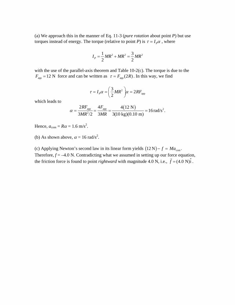
(a) We approach this in the manner of Eq. 11-3 (pure rotation about point P) but use torques instead of energy. The torque (relative to point P) is PIτ α= , where
2 21 32 2P
2I MR MR MR= + =
with the use of the parallel-axis theorem and Table 10-2(c). The torque is due to the
force and can be written as app 12 NF = app (2 )F Rτ = . In this way, we find
2app
3 22PI MR RFτ α α⎛ ⎞= = =⎜ ⎟
⎝ ⎠
which leads to ( )app app 2
2
2 4 4 12 N16rad/s .
3 /2 3 3(10 kg)(0.10 m)RF F
MR MRα = = = =
Hence, acom = Rα = 1.6 m/s2. (b) As shown above, α = 16 rad/s2. (c) Applying Newton’s second law in its linear form yields Therefore, f = –4.0 N. Contradicting what we assumed in setting up our force equation, the friction force is found to point rightward with magnitude 4.0 N, i.e., .
12 N comb g− =f Ma .
ˆ(4.0 N)if =

Chapter 12 – Student Solutions Manual 5. Three forces act on the sphere: the tension force T of the rope (acting along the rope), the force of the wall NF (acting haway from the wall), and the force of gravity mg
orizontally (acting
downward). Since the sphere is in equilibrium they sum to zero. Leθ be the angle between the rope and the vertical. Then Newton’s second law gives
t
vertical component : T cos θ – mg = 0 horizontal component: FN – T sin θ = 0. (a) We solve the first equation for the tension: T = mg/ cos θ. We substitute cos to obtain θ = +L L r/ 2 2
2 2 22 2 (0.85 kg)(9.8 m/s ) (0.080 m) (0.042 m)
9.4 N0.080 m
mg L rTL
++= = = .
(b) We solve the second equation for the normal force: sinNF T θ= .
Using sinθ = +r L r/ 2 2 , we obtain
2 2 2
2 2 2 2
(0.85 kg)(9.8 m/s )(0.042 m) 4.4 N.(0.080 m)N
Tr mg L r r mgrFL LL r L r+
= = = = =+ +
7. We take the force of the left pedestal to be F1 at x = 0, where the x axis is along the diving board. We take the force of the right pedestal to be F2 and denote its position as x = d. W is the weight of the diver, located at x = L. The following two equations result from setting the sum of forces equal to zero (with upwards positive), and the sum of torques (about x2) equal to zero:
1 2
1
0( )
F F WF d W L d 0
+ − =+ − =
(a) The second equation gives
13.0m (580 N)= 1160 N1.5m
L dF Wd
⎛ ⎞−= − = − −⎜ ⎟
⎝ ⎠
which should be rounded off to . Thus, | | 3
1 1.2 10 NF = − × 31 1.2 10 N.F = ×
(b) Since F1 is negative, indicating that this force is downward.
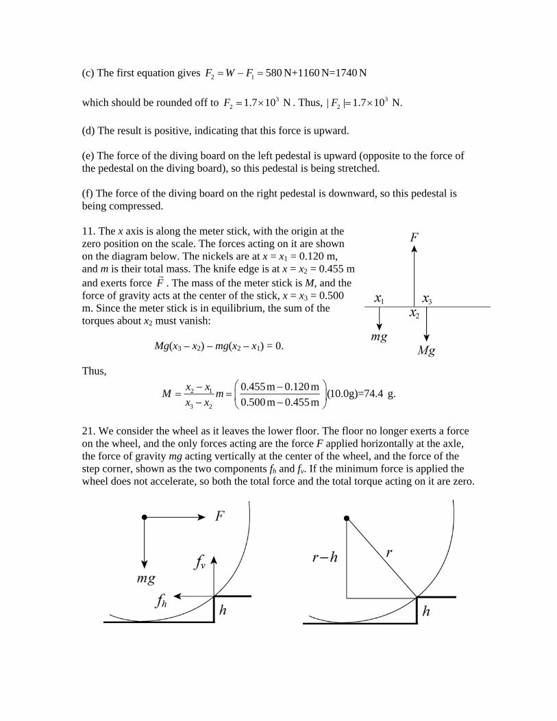
(c) The first equation gives 2 1 580 N+1160 N=1740 NF W F= − = which should be rounded off to . Thus, 3
2 1.7 10 NF = × 32| | 1.7 10 NF = × .
(d) The result is positive, indicating that this force is upward. (e) The force of the diving board on the left pedestal is upward (opposite to the force of the pedestal on the diving board), so this pedestal is being stretched. (f) The force of the diving board on the right pedestal is downward, so this pedestal is being compressed. 11. The x axis is along the meter stick, with the origin at the zero position on the scale. The forces acting on it are shown on the diagram below. The nickels are at x = x1 = 0.120 m, and m is their total mass. The knife edge is at x = x2 = 0.455 m and exerts force . The mass of the meter stick is M, and the force of gravity acts at the center of the stick, x = x
F3 = 0.500
m. Since the meter stick is in equilibrium, the sum of the torques about x2 must vanish:
Mg(x3 – x2) – mg(x2 – x1) = 0. Thus,
2 1
3 2
0.455m 0.120m (10.0g)=74.4 g.0.500m 0.455m
x xM mx x
⎛ ⎞− −= = ⎜ ⎟− −⎝ ⎠
21. We consider the wheel as it leaves the lower floor. The floor no longer exerts a force on the wheel, and the only forces acting are the force F applied horizontally at the axle, the force of gravity mg acting vertically at the center of the wheel, and the force of the step corner, shown as the two components fh and fv. If the minimum force is applied the wheel does not accelerate, so both the total force and the total torque acting on it are zero.

We calculate the torque around the step corner. The second diagram indicates that the distance from the line of F to the corner is r – h, where r is the radius of the wheel and h is the height of the step.
The distance from the line of mg to the corner is r r h rh h2 2 22+ − = −b g . Thus,
F r h mg rh h− − − =b g 2 02 . The solution for F is
2 2 2 222
2 2
2(6.00 10 m)(3.00 10 m) (3.00 10 m)2= (0.800 kg)(9.80 m/s )(6.00 10 m) (3.00 10 m)
13.6 N.
rh hF mgr h
− − −
− −
× × − ×−=
− × − ×=
33. We examine the box when it is about to tip. Since it will rotate about the lower right edge, that is where the normal force of the floor is exerted. This force is labeled on the diagram below. The force of friction is denoted by f, the applied force by F, and the force of gravity by W. Note that the force of gravity is applied at the center of the box. When the minimum force is applied the box does not accelerate, so the sum of the horizontal force components vanishes: F – f = 0, the sum of the vertical force components vanishes: , and the sum of the torques vanishes:
NF
0NF W− =
FL – WL/2 = 0. Here L is the length of a side of the box and the origin was chosen to be at the lower right edge.
(a) From the torque equation, we find
890 N 445 N.2 2
WF = = =
(b) The coefficient of static friction must be large enough that the box does not slip. The box is on the verge of slipping if μs = f/FN. According to the equations of equilibrium FN = W = 890 N and f = F = 445 N, so

445 N 0.50.890 Nsμ = =
(c) The box can be rolled with a smaller applied force if the force points upward as well as to the right. Let θ be the angle the force makes with the horizontal. The torque equation then becomes
FL cos θ + FL sin θ – WL/2 = 0, with the solution
F W=
+2(cos sin ).
θ θ
We want cosθ + sinθ to have the largest possible value. This occurs if θ = 45º, a result we can prove by setting the derivative of cosθ + sinθ equal to zero and solving for θ. The minimum force needed is
890 N 315 N.4cos 45 4cos 45
WF = = =° °
43. (a) The shear stress is given by F/A, where F is the magnitude of the force applied parallel to one face of the aluminum rod and A is the cross–sectional area of the rod. In this case F is the weight of the object hung on the end: F = mg, where m is the mass of the object. If r is the radius of the rod then A = πr2. Thus, the shear stress is
26 2
2 2
(1200kg) (9.8m/s ) 6.5 10 N/m .(0.024m)
F mgA rπ π= = = ×
(b) The shear modulus G is given by
G F Ax L
=//Δ
where L is the protrusion of the rod and Δx is its vertical deflection at its end. Thus,

6 25
10 2
( / ) (6.5 10 N/m ) (0.053m) 1.1 10 m.3.0 10 N/m
F A LxG
−×Δ = = = ×
×
55. (a) The forces acting on bucket are the force of gravity, down, and the tension force of cable A, up. Since the bucket is in equilibrium and its weight is
( )( )2 3817k 9.80m/s 8.01 10 NB BW m g g= = = × , the tension force of cable A is T . A = ×8 01 103. N (b) We use the coordinates axes defined in the diagram. Cable A makes an angle of θ2 = 66.0º with the negative y axis, cable B makes an angle of 27.0º with the positive y axis, and cable C is along the x axis. The y components of the forces must sum to zero since the knot is in equilibrium. This means TB cos 27.0º – TB A cos 66.0º = 0 and
3 3cos 66.0 cos 66.0 (8.01 10 N) 3.65 10 N.cos 27.0 cos 27.0B AT T° °⎛ ⎞= = × = ×⎜ ⎟° °⎝ ⎠
(c) The x components must also sum to zero. This means TC + TB sin 27.0º – TB
°
A sin 66.0º = 0 and
3 3
3
sin 66.0 sin 27.0 (8.01 10 N)sin 66.0 (3.65 10 N)sin 27.0
5.66 10 N.C A BT T T= °− ° = × °− ×
= ×
61. We denote the mass of the slab as m, its density as ρ , and volume as V L . The angle of inclination is
TW=26θ = ° .
(a) The component of the weight of the slab along the incline is
13 2
sin sin
kg/m )(43m)(2.5m)(12m)(9.8m/s )sin 26 1.8 10 N.
F mg Vg7
θ ρ θ3
= =
= (3.2×10 ° ≈ ×
(b) The static force of friction is
3 2
cos cos
kg/m )(43m)(2.5m)(12m)(9.8m/s )cos 26 1.4 10 N.s s N s sf F mg Vg
7
μ μ θ μ ρ θ3
= = =
= (0.39)(3.2×10 ° ≈ ×
(c) The minimum force needed from the bolts to stabilize the slab is
7 72 1 1.77 10 N 1.42 10 N 3.5 10 N.sF F f= − = × − × = × 6
If the minimum number of bolts needed is n, then , or 8 2
2 / 3.6 10 N/mF nA ≤ ×

6
8 2 4 2
3.5 10 N 15.2(3.6 10 N/m )(6.4 10 m )
n −
×≥ =
× ×
Thus 16 bolts are needed. 63. Analyzing forces at the knot (particularly helpful is a graphical view of the vector right–triangle with horizontal “side” equal to the static friction force fs and vertical “side” equal to the weight mBg of block B), we find fB s = mBBg tan θ where θ = 30°. For fs to be at its maximum value, then it must equal μsmAg where the weight of block A is mAg= (10 kg)(9.8 m/s2). Therefore,
5.0tan tan 30 0.29.10s A B sm g m gμ θ μ= ⇒ = ° =
65. With the pivot at the hinge, Eq. 12-9 leads to
– mg sinθ1 L2 + T L sin(180° – θ1 – θ2) = 0 .
where θ1 = 60° and T = mg/2. This yields θ2 = 60°. 81. When it is about to move, we are still able to apply the equilibrium conditions, but (to obtain the critical condition) we set static friction equal to its maximum value and picture the normal force as a concentrated force (upward) at the bottom corner of the cube,
directly below the point O where P is being applied. Thus, the line of action of passes through point O and exerts no torque about O (of course, a similar observation applied to the pull P). Since F
NF
NF
N = mg in this problem, we have fsmax = μmg applied a distance h away from O. And the line of action of force of gravity (of magnitude mg), which is best pictured as a concentrated force at the center of the cube, is a distance L/2 away from O. Therefore, equilibrium of torques about O produces
(8.0 cm) 0.572 2 2(7.0 cm)L Lmgh mg
hμ μ⎛ ⎞= ⇒ = = =⎜ ⎟
⎝ ⎠
for the critical condition we have been considering. We now interpret this in terms of a range of values for μ. (a) For it to slide but not tip, a value of μ less than that derived above is needed, since then — static friction will be exceeded for a smaller value of P, before the pull is strong enough to cause it to tip. Thus, μ < L/2h = 0.57 is required. (b) And for it to tip but not slide, we need μ greater than that derived above is needed, since now — static friction will not be exceeded even for the value of P which makes the

cube rotate about its front lower corner. That is, we need to have μ > L/2h = 0.57 in this case. 85. We choose an axis through the top (where the ladder comes into contact with the wall), perpendicular to the plane of the figure and take torques that would cause counterclockwise rotation as positive. Note that the line of action of the applied force
intersects the wall at a height of (F 8.0 m) / 5 1.6 m= ; in other words, the moment arm for the applied force (in terms of where we have chosen the axis) is
. The moment arm for the weight is half the horizontal distance from the wall to the base of the ladder; this works out to be
(4 / 5)(8.0 m) 6.4mr⊥ = =
2 2(10 m) (8 m) / 2 3.0 m− = . Similarly, the moment arms for the x and y components of
the force at the ground are 8.0 m and 6.0 m, respectively. Thus, with lengths in meters, we have
Fgd i
(6.4 m) (3.0 m) (8.0 m) (6.0 m) 0.z gx gF W F F yτ∑ = + + − =
In addition, from balancing the vertical forces we find that W = Fgy (keeping in mind that the wall has no friction). Therefore, the above equation can be written as
(6.4 m) (3.0 m) (8.0 m) (6.0 m) 0.z gxF W F Wτ∑ = + + − = (a) With F = 50 N and W = 200 N, the above equation yields Fgx = 35 N. Thus, in unit vector notation we obtain
ˆ ˆ(35 N)i+(200 N)j.gF = (b) With F = 150 N and W = 200 N, the above equation yields Fgx = –45 N. Therefore, in unit vector notation we obtain
ˆ ˆ( 45 N)i+(200 N)j.gF = − (c) Note that the phrase “start to move towards the wall” implies that the friction force is pointed away from the wall (in the − i direction). Now, if f = –Fgx and FN = Fgy = 200 N are related by the (maximum) static friction relation (f = fs,max = μs FN) with μs = 0.38, then we find Fgx = –76 N. Returning this to the above equation, we obtain
2(200 N) (3.0 m) (76 N) (8.0 m) 1.9 10 N.6.4 m
F += = ×
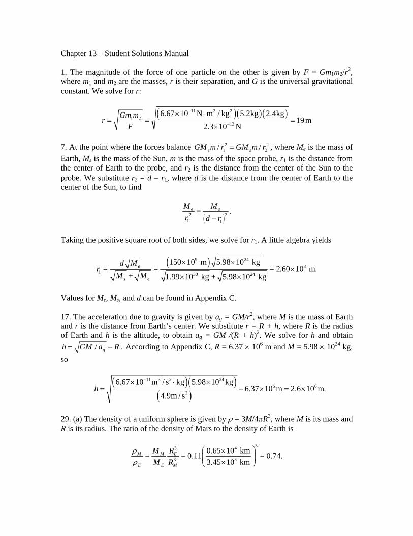
Chapter 13 – Student Solutions Manual 1. The magnitude of the force of one particle on the other is given by F = Gm1m2/r2, where m1 and m2 are the masses, r is their separation, and G is the universal gravitational constant. We solve for r:
( )( )( )11 2 21 2
12
6.67 10 N m / kg 5.2kg 2.4kg19 m
2.3 10 NGm mr
F
−
−
× ⋅= = =
×
7. At the point where the forces balance , where M2
1/e sGM m r GM m r= 22/ e is the mass of
Earth, Ms is the mass of the Sun, m is the mass of the space probe, r1 is the distance from the center of Earth to the probe, and r2 is the distance from the center of the Sun to the probe. We substitute r2 = d − r1, where d is the distance from the center of Earth to the center of the Sun, to find
( )2 21 1
= .e sM Mr d r−
Taking the positive square root of both sides, we solve for r1. A little algebra yields
( )9 248
1 30 24
150 10 m 5.98 10 kg= = = 2.60
+ 1.99 10 kg + 5.98 10 kge
s e
d Mr
M M
× ××
× ×10 m.
Values for Me, Ms, and d can be found in Appendix C. 17. The acceleration due to gravity is given by ag = GM/r2, where M is the mass of Earth and r is the distance from Earth’s center. We substitute r = R + h, where R is the radius of Earth and h is the altitude, to obtain ag = GM /(R + h)2. We solve for h and obtain
/ gh GM a= R− . According to Appendix C, R = 6.37 × 10⁶ m and M = 5.98 × 1024 kg, so
( )( )( )
11 3 2 246 6
2
6.67 10 m / s kg 5.98 10 kg6.37 10 m 2.6 10 m.
4.9m / sh
−× ⋅ ×= − × = ×
29. (a) The density of a uniform sphere is given by ρ = 3M/4πR3, where M is its mass and R is its radius. The ratio of the density of Mars to the density of Earth is
33 4
3 3
0.65 10 km= = 0.11 = 0.74.3.45 10 km
M M E
E E M
M RM R
ρρ
⎛ ⎞×⎜ ⎟×⎝ ⎠
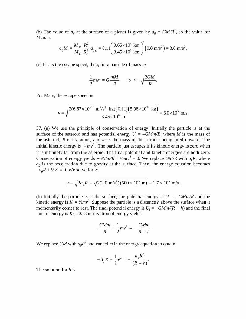
(b) The value of ag at the surface of a planet is given by ag = GM/R2, so the value for Mars is
( )22 4
2 22 3
0.65 10 km= = 0.11 9.8 m/s = 3.8 m/s .3.45 10 km
M Eg g E
E M
M Ra M aM R
⎛ ⎞×⎜ ⎟×⎝ ⎠
(c) If v is the escape speed, then, for a particle of mass m
21 2= .2
mM GMmv G vR R
⇒ =
For Mars, the escape speed is
( )( )11 3 2 243
6
2(6.67 10 m /s kg) 0.11 5.98 10 kg= 5.0 10 m/s.
3.45 10 mv
−× ⋅ ×= ×
×
37. (a) We use the principle of conservation of energy. Initially the particle is at the surface of the asteroid and has potential energy Ui = −GMm/R, where M is the mass of the asteroid, R is its radius, and m is the mass of the particle being fired upward. The initial kinetic energy is 21
2 mv . The particle just escapes if its kinetic energy is zero when it is infinitely far from the asteroid. The final potential and kinetic energies are both zero. Conservation of energy yields −GMm/R + ½mv2 = 0. We replace GM/R with agR, where ag is the acceleration due to gravity at the surface. Then, the energy equation becomes −agR + ½v2 = 0. We solve for v:
2 3 32 2(3.0 m/s ) (500 10 m) 1.7 10 m/s.gv a R= = × = × (b) Initially the particle is at the surface; the potential energy is Ui = −GMm/R and the kinetic energy is Ki = ½mv2. Suppose the particle is a distance h above the surface when it momentarily comes to rest. The final potential energy is Uf = −GMm/(R + h) and the final kinetic energy is Kf = 0. Conservation of energy yields
21 .2
GMm GMmmvR R h
− + = −+
We replace GM with agR2 and cancel m in the energy equation to obtain
221 .
2 (g
g
a Ra R v
)R h− + = −
+
The solution for h is

2 2 3 23
2 2 3 2
5
2 2(3.0 m/s ) (500 10 m) (500 10 m)2 2(3.0 m/s ) (500 10 m) (1000 m/s)
2.5 10 m.
g
g
a Rh R
a R v×
= − = − ×− × −
= ×
(c) Initially the particle is a distance h above the surface and is at rest. Its potential energy is Ui = −GMm/(R + h) and its initial kinetic energy is Ki = 0. Just before it hits the asteroid its potential energy is Uf = −GMm/R. Write 21
2 fmv for the final kinetic energy. Conservation of energy yields
21 .2
GMm GMm mvR h R
− = − ++
We substitute agR2 for GM and cancel m, obtaining
2
21 .2
gg
a Ra R v
R h− = − +
+
The solution for v is
2 2 32 3
3 3
3
2 2(3.0 m/s )(500 10 m)2 2(3.0 m/s ) (500 10 m)(500 10 m) +(1000 10 m)
1.4 10 m/s.
gg
a Rv a R
R h×
= − = × −+ ×
= ×
2
×
39. (a) The momentum of the two-star system is conserved, and since the stars have the same mass, their speeds and kinetic energies are the same. We use the principle of conservation of energy. The initial potential energy is Ui = −GM2/ri, where M is the mass of either star and ri is their initial center-to-center separation. The initial kinetic energy is zero since the stars are at rest. The final potential energy is Uf = −2GM2/ri since the final separation is ri/2. We write Mv2 for the final kinetic energy of the system. This is the sum of two terms, each of which is ½Mv2. Conservation of energy yields
2 222 .
i i
GM GM Mvr r
− = − +
The solution for v is
11 3 2 304
10
(6.67 10 m / s kg) (10 kg) 8.2 10 m/s.10 mi
GMvr
−× ⋅= = = ×
(b) Now the final separation of the centers is rf = 2R = 2 × 10⁵ m, where R is the radius of either of the stars. The final potential energy is given by Uf = −GM2/rf and the energy equation becomes −GM2/ri = −GM2/rf + Mv2. The solution for v is

11 3 2 305 10
7
1 1 1 1(6.67 10 m / s kg) (10 kg)2 10 m 10 m
1.8 10 m/s.
f i
v GMr r
−⎛ ⎞ ⎛ ⎞
= − = × ⋅ −⎜ ⎟ ⎜ ⎟⎜ ⎟ ×⎝ ⎠⎝ ⎠
= ×
45. Let N be the number of stars in the galaxy, M be the mass of the Sun, and r be the radius of the galaxy. The total mass in the galaxy is N M and the magnitude of the gravitational force acting on the Sun is F = GNM2/r2. The force points toward the galactic center. The magnitude of the Sun’s acceleration is a = v2/R, where v is its speed. If T is the period of the Sun’s motion around the galactic center then v = 2πR/T and a = 4π2R/T2. Newton’s second law yields GNM2/R2 = 4π2MR/T2. The solution for N is
2 3
2
4 .RNGT Mπ
=
The period is 2.5 × 10⁸ y, which is 7.88 × 10¹⁵ s, so
2 20 310
11 3 2 15 2 30
4 (2.2 10 m) 5.1 10 .(6.67 10 m / s kg) (7.88 10 s) (2.0 10 kg)
N π−
×= =
× ⋅ × ××
47. (a) The greatest distance between the satellite and Earth’s center (the apogee distance) is Ra = (6.37 × 10⁶ m + 360 × 103 m) = 6.73 × 10⁶ m. The least distance (perigee distance) is Rp = (6.37 × 10⁶ m + 180 × 103 m) = 6.55 × 10⁶ m. Here 6.37 × 10⁶ m is the radius of Earth. From Fig. 13-13, we see that the semi-major axis is
6 6
66.73 10 m + 6.55 10 m 6.64 10 m.2 2
a pR Ra
+ × ×= = = ×
(b) The apogee and perigee distances are related to the eccentricity e by Ra = a(1 + e) and Rp = a(1 − e). Add to obtain Ra + Rp = 2a and a = (Ra + Rp)/2. Subtract to obtain Ra − Rp = 2ae. Thus,
6 6
6 6
6.73 10 m 6.55 10 m 0.0136.2 6.73 10 m 6.55 10 m
a p a p
a p
R R R Re
a R R− − × − ×
= = = =+ × + ×
61. (a) We use the law of periods: T2 = (4π2/GM)r3, where M is the mass of the Sun (1.99 × 1030 kg) and r is the radius of the orbit. The radius of the orbit is twice the radius of Earth’s orbit: r = 2re = 2(150 × 109 m) = 300 × 109 m. Thus,
2 3 2 9 3
711 3 2 30
4 4 (300 10 m) 8.96 10 s.(6.67 10 m / s kg) (1.99 10 kg)
rTGMπ π
−
×= = = ×
× ⋅ ×
Dividing by (365 d/y) (24 h/d) (60 min/h) (60 s/min), we obtain T = 2.8 y. (b) The kinetic energy of any asteroid or planet in a circular orbit of radius r is given by K = GMm/2r, where m is the mass of the asteroid or planet. We note that it is proportional to m and inversely proportional to r. The ratio of the kinetic energy of the asteroid to the kinetic energy of Earth is K/Ke = (m/me) (re/r). We substitute m = 2.0 × 10⁻⁴me and r = 2re to obtain K/Ke = 1.0 × 10⁻⁴. 75. (a) Using Kepler’s law of periods, we obtain
23 44 2.15 10 s .T r
GMπ⎛ ⎞
= = ×⎜ ⎟⎝ ⎠
(b) The speed is constant (before she fires the thrusters), so vo = 2πr/T = 1.23 × 10⁴ m/s. (c) A two percent reduction in the previous value gives v = 0.98vo = 1.20 × 10⁴ m/s. (d) The kinetic energy is K = ½mv2 = 2.17 × 10¹¹ J. (e) The potential energy is U = −GmM/r = −4.53 × 10¹¹ J. (f) Adding these two results gives E = K + U = −2.35 × 10¹¹ J. (g) Using Eq. 13-42, we find the semi-major axis to be
74.04 10 m .2
GMmaE
−= = ×
(h) Using Kepler’s law of periods for elliptical orbits (using a instead of r) we find the new period is
3 44 2.03 10 s .T aGMπ⎛ ⎞
′ = = ×⎜ ⎟⎝ ⎠
2
This is smaller than our result for part (a) by T − T´ = 1.22 × 10³ s. (i) Elliptical orbit has a smaller period. 79. We use F = Gmsmm/r2, where ms is the mass of the satellite, mm is the mass of the meteor, and r is the distance between their centers. The distance between centers is r = R + d = 15 m + 3 m = 18 m. Here R is the radius of the satellite and d is the distance from its surface to the center of the meteor. Thus,
( )( )( )( )
11 2 211
2
6.67 10 N m / kg 20kg 7.0kg2.9 10 N.
18mF
−−
× ⋅= = ×
83. (a) We write the centripetal acceleration (which is the same for each, since they have identical mass) as rω2 where ω is the unknown angular speed. Thus,
( )
22
2 2
( ) ( )42
G M M GM Mrrr
ω= =
which gives 3 71
2 / 2.2 10 rad/s.MG rω −= = × (b) To barely escape means to have total energy equal to zero (see discussion prior to Eq. 13-28). If m is the mass of the meteoroid, then
2 41 40 8.92
GmM GmM GMmv vr r r
− − = ⇒ = = × 10 m/s .
87. We apply the work-energy theorem to the object in question. It starts from a point at the surface of the Earth with zero initial speed and arrives at the center of the Earth with final speed vf. The corresponding increase in its kinetic energy, ½mvf
2, is equal to the work done on it by Earth’s gravity: ( )F dr Kr dr= −∫ ∫ (using the notation of that Sample Problem referred to in the problem statement). Thus,
0 02 21 1( )
2 2f R Rmv F dr Kr dr KR= = − =∫ ∫
where R is the radius of Earth. Solving for the final speed, we obtain vf = R /K m . We note that the acceleration of gravity ag = g = 9.8 m/s2 on the surface of Earth is given by ag = GM/R2 = G(4πR3/3)ρ/R2, where ρ is Earth’s average density. This permits us to write K/m = 4πGρ/3 = g/R. Consequently,
2 6 3(9.8 m/s ) (6.37 10 m) 7.9 10 m/s .fK gv R R gRm R
= = = = × = ×
93. The magnitude of the net gravitational force on one of the smaller stars (of mass m) is
( )22 2 .42
GMm Gmm Gm mMr rr
⎛ ⎞+ = +⎜ ⎟⎝ ⎠
This supplies the centripetal force needed for the motion of the star:

2
2
2where .4
Gm m v rM m vr r
⎛ ⎞+ = =⎜ ⎟⎝ ⎠ T
p
Plugging in for speed v, we arrive at an equation for period T:
3 22 .
( /rT
G M mπ
=+ 4)

Chapter 14 – Student Solutions Manual 1. The pressure increase is the applied force divided by the area: Δp = F/A = F/πr2, where r is the radius of the piston. Thus
Δp = (42 N)/π(0.011 m)2 = 1.1 × 10⁵ Pa. This is equivalent to 1.1 atm. 3. The air inside pushes outward with a force given by piA, where pi is the pressure inside the room and A is the area of the window. Similarly, the air on the outside pushes inward with a force given by poA, where po is the pressure outside. The magnitude of the net force is F = (pi – po)A. Since 1 atm = 1.013 × 10⁵ Pa,
5 4(1.0 atm 0.96 atm)(1.013 10 Pa/atm)(3.4 m)(2.1 m) = 2.9 10 N.F = − × × 19. When the levels are the same the height of the liquid is h = (h1 + h2)/2, where h1 and h2 are the original heights. Suppose h1 is greater than h2. The final situation can then be achieved by taking liquid with volume A(h1 – h) and mass ρA(h1 – h), in the first vessel, and lowering it a distance h – h2. The work done by the force of gravity is
W = ρA(h1 – h)g(h – h2). We substitute h = (h1 + h2)/2 to obtain
( )2 3 3 2 4 21 2
1 1 (1.30 10 kg/m )(9.80 m/s )(4.00 10 m )(1.56 m 0.854 m)4 40.635 J
W gA h hρ −= − = × × −
=
2
.
27. (a) We use the expression for the variation of pressure with height in an incompressible fluid: p2 = p1 – ρg(y2 – y1). We take y1 to be at the surface of Earth, where the pressure is p1 = 1.01 × 10⁵ Pa, and y2 to be at the top of the atmosphere, where the pressure is p2 = 0. For this calculation, we take the density to be uniformly 1.3 kg/m3. Then,
531
2 1 3 21.01 10 Pa 7.9 10 m = 7.9 km.
(1.3 kg/m ) (9.8 m/s )py ygρ
×− = = = ×
(b) Let h be the height of the atmosphere. Now, since the density varies with altitude, we integrate
2 1 0.
hp p gρ= − ∫ dy
Assuming ρ = ρ0 (1 - y/h), where ρ0 is the density at Earth’s surface and g = 9.8 m/s2 for 0 ≤ y ≤ h, the integral becomes

2 1 0 1 00
11 .2
h yp p g dy p ghh
ρ ρ⎛ ⎞= − − = −⎜ ⎟⎝ ⎠∫
Since p2 = 0, this implies
531
3 20
2 2(1.01 10 Pa) 16 10 m = 16 km.(1.3 kg/m ) (9.8 m/s )
phgρ
×= = = ×
31. (a) The anchor is completely submerged in water of density ρw. Its effective weight is Weff = W – ρw gV, where W is its actual weight (mg). Thus,
( ) ( )2 3eff
3 2
200 N 2.04 10 m .1000 kg/m 9.8 m/sw
W WVgρ
−−= = = ×
(b) The mass of the anchor is m = ρV, where ρ is the density of iron (found in Table 14-1). Its weight in air is
( ) ( )3 2 3 27870 kg/m (2.04 10 m ) 9.80 m/s 1.57 10 N .W mg Vgρ −= = = × = × 3 35. (a) Let V be the volume of the block. Then, the submerged volume is Vs = 2V/3. Since the block is floating, the weight of the displaced water is equal to the weight of the block, so ρw Vs = ρb V, where ρw is the density of water, and ρb is the density of the block. We substitute Vs = 2V/3 to obtain
ρb = 2ρw/3 = 2(1000 kg/m3)/3 ≈ 6.7 ×10² kg/m3. (b) If ρo is the density of the oil, then Archimedes’ principle yields ρo Vs = ρbV. We substitute Vs = 0.90V to obtain ρo = ρb/0.90 = 7.4 ×10² kg/m3. 37. (a) The downward force of gravity mg is balanced by the upward buoyant force of the liquid: mg = ρg Vs. Here m is the mass of the sphere, ρ is the density of the liquid, and Vs is the submerged volume. Thus m = ρVs. The submerged volume is half the total volume of the sphere, so ( ) 31
2 4 3s oV = π r , where ro is the outer radius. Therefore,
( )3 3 32 2 800 kg/m (0.090 m) 1.22 kg.3 3om rπ πρ ⎛ ⎞= = =⎜ ⎟
⎝ ⎠
(b) The density ρm of the material, assumed to be uniform, is given by ρm = m/V, where m is the mass of the sphere and V is its volume. If ri is the inner radius, the volume is
( ) ( )( )3 33 3 4 34 4( ) 0.090 m 0.080 m 9.09 10 m .3 3o iV r rπ π −= − = − = ×
The density is
3 34 3
1.22 kg 1.3 10 kg/m .9.09 10 mmρ −= = ×
×
49. We use the equation of continuity. Let v1 be the speed of the water in the hose and v2 be its speed as it leaves one of the holes. A1 = πR2 is the cross-sectional area of the hose. If there are N holes and A2 is the area of a single hole, then the equation of continuity becomes
( )2
11 1 2 2 2 1 12
2
A Rv A v NA v v vNA Nr
= ⇒ = =
where R is the radius of the hose and r is the radius of a hole. Noting that R/r = D/d (the ratio of diameters) we find
( )( )
( )22
2 1 22
1.9cm0.91m s 8.1m s.
24 0.13cmDv v
Nd= = =
53. Suppose that a mass Δm of water is pumped in time Δt. The pump increases the potential energy of the water by Δmgh, where h is the vertical distance through which it is lifted, and increases its kinetic energy by 21
2 mvΔ , where v is its final speed. The work it does is 21
2W mgh mvΔ = Δ + Δ and its power is
21 .2
W mP ght t
Δ Δ ⎛ ⎞= = +⎜ ⎟Δ Δ ⎝ ⎠v
Now the rate of mass flow is Δm/ Δt = ρwAv, where ρw is the density of water and A is the area of the hose. The area of the hose is A = πr2 = π(0.010 m)2 = 3.14 × 10⁻⁴ m2 and
ρwAv = (1000 kg/m3) (3.14 × 10⁻⁴ m2) (5.00 m/s) = 1.57 kg/s. Thus,
( ) ( )( ) ( )22 2 5.0m s1 1.57 kg s 9.8m s 3.0m 66 W.
2 2P Av gh vρ
⎛ ⎞⎛ ⎞ ⎜ ⎟= + = + =⎜ ⎟ ⎜ ⎟⎝ ⎠ ⎝ ⎠
55. (a) We use the equation of continuity: A1v1 = A2v2. Here A1 is the area of the pipe at the top and v1 is the speed of the water there; A2 is the area of the pipe at the bottom and v2 is the speed of the water there. Thus
v2 = (A1/A2)v1 = [(4.0 cm2)/(8.0 cm2)] (5.0 m/s) = 2.5m/s. (b) We use the Bernoulli equation:

2 21 1
1 1 1 2 22 2p v gh p v ghρ ρ ρ ρ+ + = + + 2 , where ρ is the density of water, h1 is its initial altitude, and h2 is its final altitude. Thus
( ) ( )2 22 1 1 2 1 2
5 3 2 2 3
5
12
11.5 10 Pa (1000 kg m ) (5.0 m s) (2.5m s) (1000 kg m )(9.8m/s )(10 m)2
2.6 10 Pa.
p p v v g h hρ ρ= + − + −
⎡ ⎤= × + − +⎣ ⎦
= ×
2
59. (a) We use the Bernoulli equation: 21 1
1 1 1 2 22 2p v gh p v ghρ ρ ρ ρ+ + = + +22 , where h1 is
the height of the water in the tank, p1 is the pressure there, and v1 is the speed of the water there; h2 is the altitude of the hole, p2 is the pressure there, and v2 is the speed of the water there. ρ is the density of water. The pressure at the top of the tank and at the hole is atmospheric, so p1 = p2. Since the tank is large we may neglect the water speed at the top; it is much smaller than the speed at the hole. The Bernoulli equation then becomes
211 22gh v ghρ ρ ρ= + 2 and
( ) ( ) ( )22 1 22 2 9.8m s 0.30 m 2.42 m s.v g h h= − = =
The flow rate is A2v2 = (6.5 × 10⁻⁴ m2)(2.42 m/s) = 1.6 × 10⁻³ m3/s. (b) We use the equation of continuity: A2v2 = A3v3, where 1
3 2A A2= and v3 is the water speed where the area of the stream is half its area at the hole. Thus
v3 = (A2/A3)v2 = 2v2 = 4.84 m/s. The water is in free fall and we wish to know how far it has fallen when its speed is doubled to 4.84 m/s. Since the pressure is the same throughout the fall,
2 21 12 2 32 2v gh v gρ ρ ρ ρ+ = + 3h . Thus
( ) ( )
( )2 22 2
3 22 3 2
4.84 m s 2.42 m s0.90 m.
2 2 9.8m sv vh h
g−−
− = = =
67. (a) The continuity equation yields Av = aV, and Bernoulli’s equation yields
21 12 2p v V 2ρ ρΔ + = , where Δp = p1 – p2. The first equation gives V = (A/a)v. We use this
to substitute for V in the second equation, and obtain ( )22 21 12 2p v A aρ ρΔ + = v . We
solve for v. The result is

( ) ( )2
2 2
2 2 .( / ) 1
p av2
pA a Aρ ρΔ Δ
= =− − a
(b) We substitute values to obtain
( )4 2 2 3 3
3 4 2 2 4 2 2
2(32 10 m ) (55 10 Pa 41 10 Pa) 3.06 m/s.(1000 kg / m ) (64 10 m ) (32 10 m )
v−
− −
× × − ×= =
× − ×
Consequently, the flow rate is
4 2 2 3(64 10 m )(3.06 m/s) 2.0 10 m / s.Av − −= × = × 75. If we examine both sides of the U-tube at the level where the low-density liquid (with ρ = 0.800 g/cm3 = 800 kg/m3) meets the water (with ρw = 0.998 g/cm3 = 998 kg/m3), then the pressures there on either side of the tube must agree:
ρgh = ρwghw
where h = 8.00 cm = 0.0800 m, and Eq. 14-9 has been used. Thus, the height of the water column (as measured from that level) is hw = (800/998)(8.00 cm) = 6.41 cm. The volume of water in that column is therefore πr2hw = π(1.50 cm)2(6.41 cm) = 45.3 cm3.
Chapter 15 – Student Solutions Manual 3. (a) The amplitude is half the range of the displacement, or xm = 1.0 mm. (b) The maximum speed vm is related to the amplitude xm by vm = ωxm, where ω is the angular frequency. Since ω = 2πf, where f is the frequency,
( )( )3= 2 = 2 120 Hz 1.0 10 m = 0.75 m/s.m mv fxπ π −× (c) The maximum acceleration is
( ) ( )( ) ( )222 3= = 2 = 2 120 Hz 1.0 10 m = 5.7 10 m/s .m m ma x f xω π π −× × 2 2 7. (a) The motion repeats every 0.500 s so the period must be T = 0.500 s. (b) The frequency is the reciprocal of the period: f = 1/T = 1/(0.500 s) = 2.00 Hz. (c) The angular frequency ω is ω = 2πf = 2π(2.00 Hz) = 12.6 rad/s. (d) The angular frequency is related to the spring constant k and the mass m by ω = k m . We solve for k and obtain
k = mω2 = (0.500 kg)(12.6 rad/s)2 = 79.0 N/m. (e) Let xm be the amplitude. The maximum speed is
vm = ωxm = (12.6 rad/s)(0.350 m) = 4.40 m/s. (f) The maximum force is exerted when the displacement is a maximum and its magnitude is given by Fm = kxm = (79.0 N/m)(0.350 m) = 27.6 N. 9. The magnitude of the maximum acceleration is given by am = ω2xm, where ω is the angular frequency and xm is the amplitude. (a) The angular frequency for which the maximum acceleration is g is given by ω = g xm/ , and the corresponding frequency is given by
2
6
1 1 9.8 m/s 498 Hz.2 2 2 1.0 10 mm
gfx
ωπ π π −= = = =
×
(b) For frequencies greater than 498 Hz, the acceleration exceeds g for some part of the motion.
17. The maximum force that can be exerted by the surface must be less than μsFN or else the block will not follow the surface in its motion. Here, µs is the coefficient of static friction and FN is the normal force exerted by the surface on the block. Since the block does not accelerate vertically, we know that FN = mg, where m is the mass of the block. If the block follows the table and moves in simple harmonic motion, the magnitude of the maximum force exerted on it is given by
F = mam = mω2xm = m(2πf)2xm, where am is the magnitude of the maximum acceleration, ω is the angular frequency, and f is the frequency. The relationship ω = 2πf was used to obtain the last form. We substitute F = m(2πf)2xm and FN = mg into F < µsFN to obtain m(2πf)2xm < µsmg. The largest amplitude for which the block does not slip is
=2
=0.50 9.8
2 2.00 0312
2
2x gfmsμ
π πb gb gc hb g
m / s
Hz×= . .m
A larger amplitude requires a larger force at the end points of the motion. The surface cannot supply the larger force and the block slips. 19. (a) Let
=2
21x A t
Tcos πFHGIKJ
be the coordinate as a function of time for particle 1 and
=2
2 +62x A t
Tcos π πFHG
IKJ
be the coordinate as a function of time for particle 2. Here T is the period. Note that since the range of the motion is A, the amplitudes are both A/2. The arguments of the cosine functions are in radians. Particle 1 is at one end of its path (x1 = A/2) when t = 0. Particle 2 is at A/2 when 2πt/T + π/6 = 0 or t = –T/12. That is, particle 1 lags particle 2 by one-twelfth a period. We want the coordinates of the particles 0.50 s later; that is, at t = 0.50 s,
12 0.50 s= cos = 0.25
2 1.5 sAx Aπ ×⎛ ⎞ −⎜ ⎟
⎝ ⎠ and
2
2 0.50 s= cos + = 0.43 .2 1.5 s 6Ax Aπ π×⎛ ⎞ −⎜ ⎟
⎝ ⎠
Their separation at that time is x1 – x2 = –0.25A + 0.43A = 0.18A.

(b) The velocities of the particles are given by
= = 21
1v dxdt
AT
tT
π πsinFHIK
and
= = 2 +6
. 22v dx
dtA
Tt
TFπ π πH
IK sin
We evaluate these expressions for t = 0.50 s and find they are both negative-valued, indicating that the particles are moving in the same direction. 27. When the block is at the end of its path and is momentarily stopped, its displacement is equal to the amplitude and all the energy is potential in nature. If the spring potential energy is taken to be zero when the block is at its equilibrium position, then
= 12
= 12
1.3 10 0.024 = 3.7 10 . 2 2 2 2E kxm × × − N / m m Jc ha f 29. The total energy is given by E kxm= 1
22 , where k is the spring constant and xm is the
amplitude. We use the answer from part (b) to do part (a), so it is best to look at the solution for part (b) first. (a) The fraction of the energy that is kinetic is
1 3= =1 =1 = 0.4 4
K E U U 75E E E
−− − =
where the result from part (b) has been used. (b) When x xm= 1
2 the potential energy is U kx kxm= =12
2 18
2 . The ratio is
2
2
/ 8 1 0.25./ 2 4
m
m
kxUE kx
= = =
(c) Since E kxm= 1
22 and U kx= 1
22 , U/E = x xm
2 2 . We solve x xm2 2 = 1/2 for x. We should
get x xm= / 2 . 39. (a) We take the angular displacement of the wheel to be θ = θm cos(2πt/T), where θm is the amplitude and T is the period. We differentiate with respect to time to find the angular velocity: Ω = –(2π/T)θmsin(2πt/T). The symbol Ω is used for the angular velocity of the wheel so it is not confused with the angular frequency. The maximum angular velocity is

= 2 = 20.500
= 39.5 . Ωmm
Tπ π πa fa fradθ
s rad / s
(b) When θ = π/2, then θ/θm = 1/2, cos(2πt/T) = 1/2, and
( ) ( ) ( )22sin 2 1 cos 2 1 1 2 3 2t T t Tπ π= − = − = where the trigonometric identity cos2θ + sin2θ = 1 is used. Thus,
= 2 2 = 20.500
32
= 34.2 . FF
HIK −FH
IKΩ − HG
IKJ −
π π ππ
Tt
Tmθ sin s
rad rad / sa f
During another portion of the cycle its angular speed is +34.2 rad/s when its angular displacement is π/2 rad. (c) The angular acceleration is
( )2 22
2
2 2cos 2 / .md t Tdt T T
θ π πα θ π⎛ ⎞ ⎛ ⎞= = − = −⎜ ⎟ ⎜ ⎟⎝ ⎠ ⎝ ⎠
θ
When θ = π/4,
222 = 124 rad/s ,
0.500 s 4π πα ⎛ ⎞ ⎛ ⎞= − −⎜ ⎟ ⎜ ⎟
⎝ ⎠ ⎝ ⎠
or 2| | 124 rad/s .α = 43. (a) A uniform disk pivoted at its center has a rotational inertia of 21
2 Mr , where M is its mass and r is its radius. The disk of this problem rotates about a point that is displaced from its center by r+ L, where L is the length of the rod, so, according to the parallel-axis theorem, its rotational inertia is 21 1
2 2 ( 2)Mr M L r+ + . The rod is pivoted at one end and has a rotational inertia of mL2/3, where m is its mass. The total rotational inertia of the disk and rod is
2 2 2
2 2
2
1 1( )2 3
1 1(0.500kg)(0.100m) (0.500kg)(0.500m 0.100m) (0.270kg)(0.500m)2 3
0.205kg m .
I Mr M L r mL= + + +
= + + +
= ⋅
2
(b) We put the origin at the pivot. The center of mass of the disk is
= + = 0.500 m + 0.100 m = 0.600 md L r away and the center of mass of the rod is r L= = =/ ( . ) / .2 0 500 2 0 250m m away, on the same line. The distance from the pivot point to the center of mass of the disk-rod system is
= ++
=0.500 0.600 + 0.270 0.250
0.500 + 0.270= 0.477 . d M m
M md r kg m kg m
kg kg m
a fa f a fa f
(c) The period of oscillation is
( )2
2
0.205 kg m2 2 1.50 s .(0.500 kg 0.270 kg)(9.80 m/s )(0.447 m)
ITM m gd
π π ⋅= =
+ +=
51. If the torque exerted by the spring on the rod is proportional to the angle of rotation of the rod and if the torque tends to pull the rod toward its equilibrium orientation, then the rod will oscillate in simple harmonic motion. If τ = –Cθ, where τ is the torque, θ is the angle of rotation, and C is a constant of proportionality, then the angular frequency of oscillation is ω = C I/ and the period is
T I C= =2 2π π/ /ω , where I is the rotational inertia of the rod. The plan is to find the torque as a function of θ and identify the constant C in terms of given quantities. This immediately gives the period in terms of given quantities. Let be the distance from the pivot point to the wall. This is also the equilibrium length of the spring. Suppose the rod turns through the angle θ, with the left end moving away from the wall. This end is now (L/2) sin θ further from the wall and has moved a distance (L/2)(1 – cos θ) to the right. The length of the spring is now
0
2 20( / 2) (1 cos ) [ ( / 2)sin ]L L 2θ θ= − + + .
If the angle θ is small we may approximate cos θ with 1 and sin θ with θ in radians. Then the length of the spring is given by 0 / 2Lθ≈ + and its elongation is Δx = Lθ/2. The force it exerts on the rod has magnitude F = kΔx = kLθ/2. Since θ is small we may approximate the torque exerted by the spring on the rod by τ = –FL/2, where the pivot point was taken as the origin. Thus τ = –(kL2/4)θ. The constant of proportionality C that relates the torque and angle of rotation is C = kL2/4. The rotational inertia for a rod pivoted at its center is I = mL2/12, where m is its mass. See Table 10-2. Thus the period of oscillation is
T IC
mLkL
mk
= = =2 2 124
23
2
2π π π//
.

With m = 0.600 kg and k = 1850 N/m, we obtain T = 0.0653 s. 57. (a) We want to solve e–bt/2m = 1/3 for t. We take the natural logarithm of both sides to obtain –bt/2m = ln(1/3). Therefore, t = –(2m/b) ln(1/3) = (2m/b) ln 3. Thus,
=2 1.500.230
3 = 14.3 . t kg
kg / sln sa f
(b) The angular frequency is
′ = − = − =ω km
bm
2
2
2
248 00
1 500 2304 1 50
2 31..
..
. .N / mkg
kg / skg
rad / sa fa f
The period is T = 2π/ω´ = (2π)/(2.31 rad/s) = 2.72 s and the number of oscillations is
t/T = (14.3 s)/(2.72 s) = 5.27. 75. (a) The frequency for small amplitude oscillations is f g L= 1 2/ /πa f , where L is the length of the pendulum. This gives
f = =1 2 9 80 2 0 0 352/ ( . / ) / ( . ) .πa f m s m Hz. (b) The forces acting on the pendulum are the tension force T of the rod and the force of gravity mg . Newton’s second law yields T mg ma+ = , where m is the mass and is the acceleration of the pendulum. Let
aa a ae= + ′ , where ae is the acceleration of the elevator
and is the acceleration of the pendulum relative to the elevator. Newton’s second law can then be written
′a( )em g a T− + = ma ′ . Relative to the elevator the motion is exactly
the same as it would be in an inertial frame where the acceleration due to gravity is g ae− . Since g and are along the same line and in opposite directions we can find the frequency for small amplitude oscillations by replacing g with g + a
ae
e in the expression f g= ( / ) /1 2π L . Thus
f g aL
e=+
=+
=1
21
29 8 2 0
2 00 39
π π. .
.. .m / s m / s
mHz
2 2
(c) Now the acceleration due to gravity and the acceleration of the elevator are in the same direction and have the same magnitude. That is, g ae− = 0. To find the frequency for small amplitude oscillations, replace g with zero in f g L= ( / ) /1 2π . The result is zero. The pendulum does not oscillate.

83. We use vm = ωxm = 2πfxm, where the frequency is 180/(60 s) = 3.0 Hz and the amplitude is half the stroke, or xm = 0.38 m. Thus,
vm = 2π(3.0 Hz)(0.38 m) = 7.2 m/s. 89. (a) The spring stretches until the magnitude of its upward force on the block equals the magnitude of the downward force of gravity: ky = mg, where y = 0.096 m is the elongation of the spring at equilibrium, k is the spring constant, and m = 1.3 kg is the mass of the block. Thus
k = mg/y = (1.3 kg)(9.8 m/s2)/(0.096 m) = 1.33 ×10² N/m. (b) The period is given by
1 2 1.3 kg2 2 0.62 s.133 N / m
mTf k
π π πω
= = = = =
(c) The frequency is f = 1/T = 1/0.62 s = 1.6 Hz. (d) The block oscillates in simple harmonic motion about the equilibrium point determined by the forces of the spring and gravity. It is started from rest 5.0 cm below the equilibrium point so the amplitude is 5.0 cm. (e) The block has maximum speed as it passes the equilibrium point. At the initial position, the block is not moving but it has potential energy
( )( )( ) ( )( )22 21 11.3 kg 9.8 m/s 0.146 m 133 N / m 0.146 m 0.44 J.2 2i i iU mgy ky= − + = − + = −
When the block is at the equilibrium point, the elongation of the spring is y = 9.6 cm and the potential energy is
( )( )( ) ( )( )22 21 11.3 kg 9.8 m/s 0.096 m 133 N / m 0.096 m 0.61 J.2 2fU mgy ky= − + = − + = −
We write the equation for conservation of energy as U U mvi f= + 1
22 and solve for v:
( ) ( )2 2 0.44J 0.61J0.51 m/s.
1.3kgi fU U
vm− − +
= = =
91. We note that for a horizontal spring, the relaxed position is the equilibrium position (in a regular simple harmonic motion setting); thus, we infer that the given v = 5.2 m/s at x = 0 is the maximum value vm (which equals ωxm where ω = =k m/ 20 rad / s ).
(a) Since ω = 2π f, we find f = 3.2 Hz. (b) We have vm = 5.2 m/s = (20 rad/s)xm, which leads to xm = 0.26 m. (c) With meters, seconds and radians understood,
(0.26 m) cos(20 )(5.2 m/s)sin(20 ).
x tv t
φφ
= += − +
The requirement that x = 0 at t = 0 implies (from the first equation above) that either φ = +π/2 or φ = –π/2. Only one of these choices meets the further requirement that v > 0 when t = 0; that choice is φ = –π/2. Therefore,
= 0.26 202
= 0.26 20 . x tcos sin−FHG tIKJ
π b g

Chapter 16 – Student Solutions Manual 15. The wave speed v is given by v = τ μ , where τ is the tension in the rope and μ is the linear mass density of the rope. The linear mass density is the mass per unit length of rope:
μ = m/L = (0.0600 kg)/(2.00 m) = 0.0300 kg/m. Thus,
500 N 129 m s.0.0300kg m
v = =
17. (a) The amplitude of the wave is ym=0.120 mm. (b) The wave speed is given by v = τ μ , where τ is the tension in the string and μ is the
linear mass density of the string, so the wavelength is λ = v/f = τ μ /f and the angular wave number is
( ) 12 0.50kg2 2 100 Hz 141m .10 N
k f m −π= = π = π =
λμτ
(c) The frequency is f = 100 Hz, so the angular frequency is
ω = 2πf = 2π(100 Hz) = 628 rad/s. (d) We may write the string displacement in the form y = ym sin(kx + ωt). The plus sign is used since the wave is traveling in the negative x direction. In summary, the wave can be expressed as
( ) ( ) ( )1 10.120mm sin 141m + 628s .y x t− −⎡ ⎤= ⎣ ⎦
21. (a) We read the amplitude from the graph. It is about 5.0 cm. (b) We read the wavelength from the graph. The curve crosses y = 0 at about x = 15 cm and again with the same slope at about x = 55 cm, so
λ = (55 cm – 15 cm) = 40 cm = 0.40 m. (c) The wave speed is / ,v = τ μ where τ is the tension in the string and μ is the linear mass density of the string. Thus,
3
3.6 N 12 m/s.25 10 kg/m
v −= =×
(d) The frequency is f = v/λ = (12 m/s)/(0.40 m) = 30 Hz and the period is
T = 1/f = 1/(30 Hz) = 0.033 s. (e) The maximum string speed is
um = ωym = 2πfym = 2π(30 Hz) (5.0 cm) = 940 cm/s = 9.4 m/s. (f) The angular wave number is k = 2π/λ = 2π/(0.40 m) = 16 m–1. (g) The angular frequency is ω = 2πf = 2π(30 Hz) = 1.9×10² rad/s (h) According to the graph, the displacement at x = 0 and t = 0 is 4.0 × 10⁻² m. The formula for the displacement gives y(0, 0) = ym sin φ. We wish to select φ so that 5.0 × 10⁻² sin φ = 4.0 × 10⁻². The solution is either 0.93 rad or 2.21 rad. In the first case the function has a positive slope at x = 0 and matches the graph. In the second case it has negative slope and does not match the graph. We select φ = 0.93 rad. (i) The string displacement has the form y (x, t) = ym sin(kx + ωt + φ). A plus sign appears in the argument of the trigonometric function because the wave is moving in the negative x direction. Using the results obtained above, the expression for the displacement is
( )2 1 1( , ) 5.0 10 m sin (16 m ) (190s ) 0.93 .− − −⎡ ⎤= × + +⎣ ⎦y x t x t 31. The displacement of the string is given by
( ) (sin( ) sin( )m my y kx t y kx tω ω φ= − + − + )1 12 22 cos sinmy kx tφ ω φ+= − ,
where φ = π/2. The amplitude is
( )122 cosmA y φ= 2 cos( / 4) 1.41m my y= π = .
35. The phasor diagram is shown below: y1m and y2m represent the original waves and ym represents the resultant wave. The phasors corresponding to the two constituent waves make an angle of 90° with each other, so the triangle is a right triangle. The Pythagorean theorem gives
2 2 2 2 21 2 (3.0cm) (4.0cm) (25cm)m m my y y= + = + = 2 .
Thus ym = 5.0 cm.

41. Possible wavelengths are given by λ = 2L/n, where L is the length of the wire and n is an integer. The corresponding frequencies are given by f = v/λ = nv/2L, where v is the wave speed. The wave speed is given by /v Lτ μ τ= = ,M where τ is the tension in the wire, μ is the linear mass density of the wire, and M is the mass of the wire. μ = M/L was used to obtain the last form. Thus
250 N (7.91 Hz).2 2 2 (10.0 m) (0.100 kg)nn L n nf nL M LM
τ τ= = = =
(a) The lowest frequency is 1 7.91 Hz.f = (b) The second lowest frequency is 2 2(7.91 Hz) 15.8 Hz.f = = (c) The third lowest frequency is 3 3(7.91 Hz) 23.7 Hz.f = = 43. (a) The wave speed is given by ,v τ μ= where τ is the tension in the string and μ is the linear mass density of the string. Since the mass density is the mass per unit length, μ = M/L, where M is the mass of the string and L is its length. Thus
(96.0 N) (8.40 m) 82.0 m/s.0.120 kg
LvM
= = =τ
(b) The longest possible wavelength λ for a standing wave is related to the length of the string by L = λ/2, so λ = 2L = 2(8.40 m) = 16.8 m. (c) The frequency is f = v/λ = (82.0 m/s)/(16.8 m) = 4.88 Hz. 47. (a) The resonant wavelengths are given by λ = 2L/n, where L is the length of the string and n is an integer, and the resonant frequencies are given by f = v/λ = nv/2L, where v is the wave speed. Suppose the lower frequency is associated with the integer n. Then, since there are no resonant frequencies between, the higher frequency is associated

with n + 1. That is, f1 = nv/2L is the lower frequency and f2 = (n + 1)v/2L is the higher. The ratio of the frequencies is
2
1
1.f nf n
+=
The solution for n is
1
2 1
315 Hz 3.420 Hz 315 Hz
fnf f
= =− −
=
The lowest possible resonant frequency is f = v/2L = f1/n = (315 Hz)/3 = 105 Hz. (b) The longest possible wavelength is λ = 2L. If f is the lowest possible frequency then
v = λf = 2Lf = 2(0.75 m)(105 Hz) = 158 m/s. 53. (a) The waves have the same amplitude, the same angular frequency, and the same angular wave number, but they travel in opposite directions. We take them to be
y1 = ym sin(kx – ωt), y2 = ym sin(kx + ωt). The amplitude ym is half the maximum displacement of the standing wave, or 5.0 × 10⁻³ m. (b) Since the standing wave has three loops, the string is three half-wavelengths long: L = 3λ/2, or λ = 2L/3. With L = 3.0m, λ = 2.0 m. The angular wave number is k = 2π/λ = 2π/(2.0 m) = 3.1 m–1. (c) If v is the wave speed, then the frequency is
( )( )
3 100m s3 50 Hz.2 2 3.0m
v vfL
= = = =λ
The angular frequency is the same as that of the standing wave, or ω = 2π f = 2π(50 Hz) = 314 rad/s. (d) The two waves are
( ) ( ) ( )3 11 5.0 10 m sin 3.14 m 314s 1y x t− − −⎡ ⎤= × −⎣ ⎦
and
( ) ( ) ( )3 12 5.0 10 m sin 3.14 m 314s .1y x t− − −⎡ ⎤= × +⎣ ⎦

Thus, if one of the waves has the form ( , ) sin( )my x t y kx tω= + , then the other wave must have the form '( , ) sin( )my x t y kx tω= − . The sign in front of ω for is minus. '( , )y x t 61. (a) The phasor diagram is shown here: y1, y2, and y3 represent the original waves and ym represents the resultant wave.
The horizontal component of the resultant is ymh = y1 – y3 = y1 – y1/3 = 2y1/3. The vertical component is ymv = y2 = y1/2. The amplitude of the resultant is
2 22 2 1 1
1 12 5 0.83 .3 2 6m mh mvy yy y y y⎛ ⎞ ⎛ ⎞= + = + = =⎜ ⎟ ⎜ ⎟
⎝ ⎠ ⎝ ⎠y
(b) The phase constant for the resultant is
1 1 11
1
2 3tan tan tan 0.644 rad 37 .2 3 4
mv
mh
y yy y
φ − − −⎛ ⎞ ⎛ ⎞ ⎛ ⎞= = = =⎜ ⎟ ⎜ ⎟ ⎜ ⎟⎝ ⎠⎝ ⎠⎝ ⎠
= °
(c) The resultant wave is
15 sin ( 0.644 rad).6
y y kx tω= − +
The graph below shows the wave at time t = 0. As time goes on it moves to the right with speed v = ω/k.
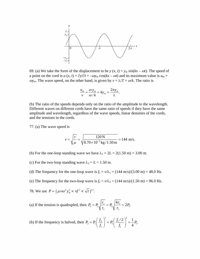
69. (a) We take the form of the displacement to be y (x, t) = ym sin(kx – ωt). The speed of a point on the cord is u (x, t) = ∂y/∂t = –ωym cos(kx – ωt) and its maximum value is um = ωym. The wave speed, on the other hand, is given by v = λ/T = ω/k. The ratio is
2 ./
m mm
u y ykyv k
mπ= = =
λωω
(b) The ratio of the speeds depends only on the ratio of the amplitude to the wavelength. Different waves on different cords have the same ratio of speeds if they have the same amplitude and wavelength, regardless of the wave speeds, linear densities of the cords, and the tensions in the cords. 77. (a) The wave speed is
3
120 N 144 m/s.8.70 10 kg /1.50m−= = =
×v τ
μ
(b) For the one-loop standing wave we have λ1 = 2L = 2(1.50 m) = 3.00 m. (c) For the two-loop standing wave λ2 = L = 1.50 m. (d) The frequency for the one-loop wave is f1 = v/λ1 = (144 m/s)/(3.00 m) = 48.0 Hz. (e) The frequency for the two-loop wave is f2 = v/λ2 = (144 m/s)/(1.50 m) = 96.0 Hz. 78. We use 2 2 2 21
2 .mP y vf= ∝ ∝μνω τ f
(a) If the tension is quadrupled, then 2 12 1 1
1 1
4 2 .P P P P= = =τ ττ τ 1
(b) If the frequency is halved, then 2 2
2 12 1 1 1
1 1
/ 2 1 .4
f fP P P Pf f
⎛ ⎞ ⎛ ⎞= = =⎜ ⎟ ⎜ ⎟⎝ ⎠ ⎝ ⎠

87. (a) From the frequency information, we find ω = 2πf = 10π rad/s. A point on the rope undergoing simple harmonic motion (discussed in Chapter 15) has maximum speed as it passes through its "middle" point, which is equal to ymω. Thus,
5.0 m/s = ymω ⇒ ym = 0.16 m . (b) Because of the oscillation being in the fundamental mode (as illustrated in Fig. 16-23(a) in the textbook), we have λ = 2L = 4.0 m. Therefore, the speed of waves along the rope is v = fλ = 20 m/s. Then, with μ = m/L = 0.60 kg/m, Eq. 16-26 leads to
v = τμ ⇒ τ = μ v2 = 240 N . 22.4 10 N≈ ×
(c) We note that for the fundamental, k = 2π/λ = π/L, and we observe that the anti-node having zero displacement at t = 0 suggests the use of sine instead of cosine for the simple harmonic motion factor. Now, if the fundamental mode is the only one present (so the amplitude calculated in part (a) is indeed the amplitude of the fundamental wave pattern) then we have
y = (0.16 m) sin ⎝⎜⎛
⎠⎟⎞πx
2 sin (10πt) 1(0.16 m)sin[(1.57 m ) ]sin[(31.4 rad/s) ]x t−=
89. (a) The wave speed is
( ) ./( )Δ Δ + Δ
= = =+ Δ
F k kvm mμ
(b) The time required is
2 ( ) 2 ( ) 2 1( ) /
mtv kk m
π + Δ π + Δ= = = π .+
ΔΔ + Δ
Thus if , then /Δ 1 / 1/t∝ Δ ∝ Δ ; 1 and if /Δ , then
2 / const m kπ = t.
Chapter 17 – Student Solutions Manual 5. Let tf be the time for the stone to fall to the water and ts be the time for the sound of the splash to travel from the water to the top of the well. Then, the total time elapsed from dropping the stone to hearing the splash is t = tf + ts. If d is the depth of the well, then the kinematics of free fall gives 21
2 fd gt= , or 2 / .ft d= g The sound travels at a constant
speed vs, so d = vsts, or ts = d/vs. Thus the total time is 2 / / st d g d= + v . This equation is
to be solved for d. Rewrite it as 2 / / sd g t d v= − and square both sides to obtain
2d/g = t2 – 2(t/vs)d + (1 + 2sv )d2.
Now multiply by g 2
sv and rearrange to get
gd2 – 2vs(gt + vs)d + g 2sv t2 = 0.
This is a quadratic equation for d. Its solutions are
( )22 22 ( ) 4 4.
2s s s s sv gt v v gt v g v t
dg
+ ± + −=
2 2
The physical solution must yield d = 0 for t = 0, so we take the solution with the negative sign in front of the square root. Once values are substituted the result d = 40.7 m is obtained. 7. If d is the distance from the location of the earthquake to the seismograph and vs is the speed of the S waves then the time for these waves to reach the seismograph is ts. = d/vs. Similarly, the time for P waves to reach the seismograph is tp = d/vp. The time delay is
Δt = (d/vs) – (d/vp) = d(vp – vs)/vsvp, so
3(4.5 km/s)(8.0 km/s)(3.0 min)(60s /min) 1.9 10 km.( ) 8.0 km/s 4.5km/s
s p
p s
v v td
v vΔ
= = = ×− −
We note that values for the speeds were substituted as given, in km/s, but that the value for the time delay was converted from minutes to seconds. 9. (a) Using λ = v/f, where v is the speed of sound in air and f is the frequency, we find
5
6
343m/s 7.62 10 m.4.50 10 Hz
−λ = = ××

(b) Now, λ = v/f, where v is the speed of sound in tissue. The frequency is the same for air and tissue. Thus
λ = (1500 m/s)/(4.50 × 106 Hz) = 3.33 × 10⁻⁴ m. 19. Let L1 be the distance from the closer speaker to the listener. The distance from the other speaker to the listener is 2
2 12L L d= + , where d is the distance between the
speakers. The phase difference at the listener is φ = 2π(L2 – L1)/λ, where λ is the wavelength. For a minimum in intensity at the listener, φ = (2n + 1)π, where n is an integer. Thus λ = 2(L2 – L1)/(2n + 1). The frequency is
( ) ( )2 2 2 21 1
(2 1) (2 1)(343m/s) (2 1)(343Hz).2 2 (3.75m) (2.00m) 3.75m
v n v nf nL d L
+ += = = = +
λ + − + −
Now 20,000/343 = 58.3, so 2n + 1 must range from 0 to 57 for the frequency to be in the audible range. This means n ranges from 0 to 28. (a) The lowest frequency that gives minimum signal is (n = 0) min,1 343 Hz.f = (b) The second lowest frequency is (n = 1) min,2 min,1[2(1) 1]343 Hz 1029 Hz 3 .f f= + = = Thus, the factor is 3. (c) The third lowest frequency is (n=2) min,3 min,1[2(2) 1]343 Hz 1715 Hz 5 .f f= + = = Thus, the factor is 5. For a maximum in intensity at the listener, φ = 2nπ, where n is any positive integer. Thus
( )2 21 1(1/ )n L d Lλ = + − and
2 2 2 21 1
(343m/s) (686 Hz).(3.75m) (2.00 m) 3.75m
v nv nf nL d L
= = = =λ + − + −
Since 20,000/686 = 29.2, n must be in the range from 1 to 29 for the frequency to be audible. (d) The lowest frequency that gives maximum signal is (n =1) max,1 686 Hz.f = (e) The second lowest frequency is (n = 2) max,2 max,12(686 Hz) 1372 Hz 2 .f f= = = Thus, the factor is 2.

(f) The third lowest frequency is (n = 3) max,3 max,13(686 Hz) 2058 Hz 3 .f f= = = Thus, the factor is 3. 25. The intensity is the rate of energy flow per unit area perpendicular to the flow. The rate at which energy flow across every sphere centered at the source is the same, regardless of the sphere radius, and is the same as the power output of the source. If P is the power output and I is the intensity a distance r from the source, then P = IA = 4πr2I, where A (= 4πr2) is the surface area of a sphere of radius r. Thus
P = 4π(2.50 m)2 (1.91 × 10⁻⁴ W/m2) = 1.50 × 10⁻² W. 29. (a) Let I1 be the original intensity and I2 be the final intensity. The original sound level is β1 = (10 dB) log(I1/I0) and the final sound level is β2 = (10 dB) log(I2/I0), where I0 is the reference intensity. Since β2 = β1 + 30 dB which yields
(10 dB) log(I2/I0) = (10 dB) log(I1/I0) + 30 dB, or
(10 dB) log(I2/I0) – (10 dB) log(I1/I0) = 30 dB. Divide by 10 dB and use log(I2/I0) – log(I1/I0) = log(I2/I1) to obtain log(I2/I1) = 3. Now use each side as an exponent of 10 and recognize that ( )2 1log
210 /I I1I I= . The result is I2/I1
= 103. The intensity is increased by a factor of 1.0×10³. (b) The pressure amplitude is proportional to the square root of the intensity so it is increased by a factor of 1000 32.= 43. (a) When the string (fixed at both ends) is vibrating at its lowest resonant frequency, exactly one-half of a wavelength fits between the ends. Thus, λ = 2L. We obtain
v = fλ = 2Lf = 2(0.220 m)(920 Hz) = 405 m/s. (b) The wave speed is given by / ,v τ μ= where τ is the tension in the string and μ is the linear mass density of the string. If M is the mass of the (uniform) string, then μ = M/L. Thus
τ = μv2 = (M/L)v2 = [(800 × 10–6 kg)/(0.220 m)] (405 m/s)2 = 596 N. (c) The wavelength is λ = 2L = 2(0.220 m) = 0.440 m. (d) The frequency of the sound wave in air is the same as the frequency of oscillation of the string. The wavelength is different because the wave speed is different. If va is the speed of sound in air the wavelength in air is

λa = va/f = (343 m/s)/(920 Hz) = 0.373 m. 45. (a) Since the pipe is open at both ends there are displacement antinodes at both ends and an integer number of half-wavelengths fit into the length of the pipe. If L is the pipe length and λ is the wavelength then λ = 2L/n, where n is an integer. If v is the speed of sound then the resonant frequencies are given by f = v/λ = nv/2L. Now L = 0.457 m, so
f = n(344 m/s)/2(0.457 m) = 376.4n Hz. To find the resonant frequencies that lie between 1000 Hz and 2000 Hz, first set f = 1000 Hz and solve for n, then set f = 2000 Hz and again solve for n. The results are 2.66 and 5.32, which imply that n = 3, 4, and 5 are the appropriate values of n. Thus, there are 3 frequencies. (b) The lowest frequency at which resonance occurs is (n = 3) f = 3(376.4 Hz) = 1129 Hz. (c) The second lowest frequency at which resonance occurs is (n = 4)
f = 4(376.4 Hz) = 1506 Hz. 47. The string is fixed at both ends so the resonant wavelengths are given by λ = 2L/n, where L is the length of the string and n is an integer. The resonant frequencies are given by f = v/λ = nv/2L, where v is the wave speed on the string. Now /v = τ μ , where τ is the tension in the string and μ is the linear mass density of the string. Thus
( / 2 ) /f n L= τ μ . Suppose the lower frequency is associated with n = n1 and the higher frequency is associated with n = n1 + 1. There are no resonant frequencies between so you know that the integers associated with the given frequencies differ by 1. Thus
1 1( / 2 ) /f n L= τ μ and
1 12 1
1 1 .2 2 2 2
n nf fL L L L+
= = + = +1τ τ τ τ
μ μ μ μ
This means 2 1 (1/ 2 ) /f f L− = τ μ and
2 2 2 3 22 14 ( ) 4(0.300 m) (0.650 10 kg/m)(1320 Hz 880 Hz) 45.3 N.L f fτ μ −= − = × − =
53. Each wire is vibrating in its fundamental mode so the wavelength is twice the length of the wire (λ = 2L) and the frequency is / (1/ 2 ) /f v L= λ = τ μ , where /v τ μ= is the wave speed for the wire, τ is the tension in the wire, and μ is the linear mass density of the wire. Suppose the tension in one wire is τ and the oscillation frequency of that wire is f1. The tension in the other wire is τ + Δτ and its frequency is f2. You want to calculate

Δτ/τ for f1 = 600 Hz and f2 = 606 Hz. Now, 1 (1/ 2 ) /f L= τ μ and
2 (1/ 2 ) ( /f L= + Δτ τ μ , so
2 1/ ( ) / 1 ( /f f = + Δ = + Δ ).τ τ τ τ τ This leads to 2 2
2 1/ ( / ) 1 [(606 Hz) /(600 Hz)] 1 0.020.f fΔ = − = − =τ τ 65. (a) The expression for the Doppler shifted frequency is
,D
S
v vf fv v
±′ =∓
where f is the unshifted frequency, v is the speed of sound, vD is the speed of the detector (the uncle), and vS is the speed of the source (the locomotive). All speeds are relative to the air. The uncle is at rest with respect to the air, so vD = 0. The speed of the source is vS = 10 m/s. Since the locomotive is moving away from the uncle the frequency decreases and we use the plus sign in the denominator. Thus
343m/s(500.0 Hz) 485.8Hz.343m/s + 10.00m/sS
vf fv v
⎛ ⎞′ = = =⎜ ⎟+ ⎝ ⎠
(b) The girl is now the detector. Relative to the air she is moving with speed vD = 10.00 m/s toward the source. This tends to increase the frequency and we use the plus sign in the numerator. The source is moving at vS = 10.00 m/s away from the girl. This tends to decrease the frequency and we use the plus sign in the denominator. Thus (v + vD) = (v + vS) and f′ = f = 500.0 Hz. (c) Relative to the air the locomotive is moving at vS = 20.00 m/s away from the uncle. Use the plus sign in the denominator. Relative to the air the uncle is moving at vD = 10.00 m/s toward the locomotive. Use the plus sign in the numerator. Thus
343m/s + 10.00m/s(500.0 Hz) 486.2 Hz.343m/s + 20.00m/s
D
S
v vf fv v
⎛ ⎞+′ = = =⎜ ⎟+ ⎝ ⎠
(d) Relative to the air the locomotive is moving at vS = 20.00 m/s away from the girl and the girl is moving at vD = 20.00 m/s toward the locomotive. Use the plus signs in both the numerator and the denominator. Thus (v + vD) = (v + vS) and f′ = f = 500.0 Hz. 77. The siren is between you and the cliff, moving away from you and towards the cliff. Both “detectors” (you and the cliff) are stationary, so vD = 0 in Eq. 17–47 (and see the discussion in the textbook immediately after that equation regarding the selection of ± signs). The source is the siren with vS = 10 m/s. The problem asks us to use v = 330 m/s for the speed of sound.

(a) With f = 1000 Hz, the frequency fy you hear becomes
20 970.6Hz 9.7 10 Hz.yS
vf fv v
⎛ ⎞+= = ≈ ×⎜ ⎟+⎝ ⎠
(b) The frequency heard by an observer at the cliff (and thus the frequency of the sound reflected by the cliff, ultimately reaching your ears at some distance from the cliff) is
30 1031.3Hz 1.0 10 Hz.cS
vf fv v
⎛ ⎞+= = ≈ ×⎜ ⎟−⎝ ⎠
(c) The beat frequency is fc – fy = 60 beats/s (which, due to specific features of the human ear, is too large to be perceptible). 81. (a) With r = 10 m in Eq. 17–28, we have
2 10W.4
PI Pr
= ⇒ =π
(b) Using that value of P in Eq. 17–28 with a new value for r, we obtain
( )2 2W0.032 .m4 5.0
PI = =π
Alternatively, a ratio I′ /I = (r/r′ )2 could have been used. (c) Using Eq. 17–29 with I = 0.0080 W/m2, we have
0
10log 99dBII
= =β
where I0 = 1.0 × 10⁻¹² W/m2. 85. (a) The intensity is given by 2 21
2 ,mI v sρ ω= where ρ is the density of the medium, v is the speed of sound, ω is the angular frequency, and sm is the displacement amplitude. The displacement and pressure amplitudes are related by Δpm = ρvωsm, so sm = Δpm/ρvω and I = (Δpm)2/2ρv. For waves of the same frequency the ratio of the intensity for propagation in water to the intensity for propagation in air is
2
,w mw a
a ma w
a
w
I p vI p v
ρρ
⎛ ⎞Δ= ⎜ ⎟Δ⎝ ⎠

where the subscript a denotes air and the subscript w denotes water. Since Ia = Iw,
3 3
3
(0.998 10 kg/m )(1482 m/s) 59.7.(1.21kg/m )(343m/s)
mw w w
ma a a
p vp v
Δ ×= = =
Δρρ
The speeds of sound are given in Table 17-1 and the densities are given in Table 15-1. (b) Now, Δpmw = Δpma, so
34
3 3
(1.21kg/m )(343m/s) 2.81 10 .(0.998 10 kg/m )(1482 m/s)
w a a
a w w
I vI v
−= = = ××
ρρ
87. (a) When the right side of the instrument is pulled out a distance d the path length for sound waves increases by 2d. Since the interference pattern changes from a minimum to the next maximum, this distance must be half a wavelength of the sound. So 2d = λ/2, where λ is the wavelength. Thus λ = 4d and, if v is the speed of sound, the frequency is
f = v/λ = v/4d = (343 m/s)/4(0.0165 m) = 5.2 × 10³ Hz. (b) The displacement amplitude is proportional to the square root of the intensity (see Eq. 17–27). Write mI Cs= , where I is the intensity, sm is the displacement amplitude, and C is a constant of proportionality. At the minimum, interference is destructive and the displacement amplitude is the difference in the amplitudes of the individual waves: sm = sSAD – sSBD, where the subscripts indicate the paths of the waves. At the maximum, the waves interfere constructively and the displacement amplitude is the sum of the amplitudes of the individual waves: sm = sSAD + sSBD. Solve
100 ( )SAD SBDC s s= − and 900 ( )SAD SBDC s s= − for sSAD and sSBD. Add the equations to obtain
SADs = ( 100 900 / 2 20 / ,C C+ = then subtract them to obtain
SBDs = ( 900 100) / 2 10 / .C C− = The ratio of the amplitudes is sSAD/sSBD = 2. (c) Any energy losses, such as might be caused by frictional forces of the walls on the air in the tubes, result in a decrease in the displacement amplitude. Those losses are greater on path B since it is longer than path A.

101. (a) The blood is moving towards the right (towards the detector), because the Doppler shift in frequency is an increase: Δf > 0. (b) The reception of the ultrasound by the blood and the subsequent remitting of the signal by the blood back toward the detector is a two step process which may be compactly written as
bloodwhere cos .xx
x
v vf f f v vv v
θ⎛ ⎞+
+ Δ = =⎜ ⎟−⎝ ⎠
If we write the ratio of frequencies as R = (f + Δf)/f, then the solution of the above equation for the speed of the blood is
( )( )blood
10.90m/s
1 cosR v
vR
−= =
+ θ
where v = 1540 m/s, θ = 20°, and R = 1 + 5495/5 × 106. (c) We interpret the question as asking how Δf (still taken to be positive, since the detector is in the “forward” direction) changes as the detection angle θ changes. Since larger θ means smaller horizontal component of velocity vx then we expect Δf to decrease towards zero as θ is increased towards 90°.
Chapter 18 – Student Solutions Manual 8. The change in length for the aluminum pole is
60 1 (33m)(23 10 / C )(15 C) = 0.011m.A Tα −Δ = Δ = × ° °
15. If Vc is the original volume of the cup, αa is the coefficient of linear expansion of aluminum, and ΔT is the temperature increase, then the change in the volume of the cup is ΔVc = 3αa Vc ΔT. See Eq. 18-11. If β is the coefficient of volume expansion for glycerin then the change in the volume of glycerin is ΔVg = βVc ΔT. Note that the original volume of glycerin is the same as the original volume of the cup. The volume of glycerin that spills is
( ) ( ) ( ) ( )( )4 6 3
3
3 5.1 10 / C 3 23 10 / C 100cm 6.0 C
0.26cm .
g c a cV V V Tβ α − −⎡ ⎤Δ −Δ = − Δ = × ° − × ° °⎣ ⎦=
21. Consider half the bar. Its original length is 0 0 / 2L= and its length after the temperature increase is 0 0 T= + Δα . The old position of the half-bar, its new position, and the distance x that one end is displaced form a right triangle, with a hypotenuse of length , one side of length , and the other side of length x. The Pythagorean theorem yields Since the change in length is small we may approximate (1 + α ΔT )
02 2 2 2 2 2
0 0 0(1 ) .x α= − = + Δ −T2 by 1 + 2α ΔT, where the small term (α ΔT )2 was neglected.
Then, 2 2 2 2 2
0 0 0 02 2x T T= + Δ − = Δα α and
( )( )6 20
3.77 m2 2 25 10 /C 32 C 7.5 10 m.2
x Tα − −= Δ = × ° ° = ×
25. The melting point of silver is 1235 K, so the temperature of the silver must first be raised from 15.0° C (= 288 K) to 1235 K. This requires heat
4( ) (236J/kg K)(0.130kg)(1235 C 288 C) 2.91 10 J.f iQ cm T T= − = ⋅ ° − ° = × Now the silver at its melting point must be melted. If LF is the heat of fusion for silver this requires
( ) ( )3 40.130 kg 105 10 J/kg 1.36 10 J.FQ mL= = × = × The total heat required is ( 2.91 × 10⁴ J + 1.36 × 10⁴ J ) = 4.27 × 10⁴ J.
27. The mass m = 0.100 kg of water, with specific heat c = 4190 J/kg·K, is raised from an initial temperature Ti = 23°C to its boiling point Tf = 100°C. The heat input is given by Q = cm(Tf – Ti). This must be the power output of the heater P multiplied by the time t; Q = Pt. Thus,
( ) ( ) ( )( ) 4190J/kg K 0.100kg 100 C 23 C160s.
200J/sf icm T TQt
P P− ⋅ ° − °
= = = =
41. (a) We work in Celsius temperature, which poses no difficulty for the J/kg·K values of specific heat capacity (see Table 18-3) since a change of Kelvin temperature is numerically equal to the corresponding change on the Celsius scale. There are three possibilities: • None of the ice melts and the water-ice system reaches thermal equilibrium at a temperature that is at or below the melting point of ice. • The system reaches thermal equilibrium at the melting point of ice, with some of the ice melted. • All of the ice melts and the system reaches thermal equilibrium at a temperature at or above the melting point of ice. First, suppose that no ice melts. The temperature of the water decreases from TWi = 25°C to some final temperature Tf and the temperature of the ice increases from TIi = –15°C to Tf. If mW is the mass of the water and cW is its specific heat then the water rejects heat
| | ( )W W Wi fQ c m T T .= − If mI is the mass of the ice and cI is its specific heat then the ice absorbs heat
( )I I f IiQ c m T T .= − Since no energy is lost to the environment, these two heats (in absolute value) must be the same. Consequently,
( ) (W W Wi f I I f Iic m T T c m T T ).− = − The solution for the equilibrium temperature is
(4190J / kg K)(0.200kg)(25 C) (2220J/kg K)(0.100kg)( 15 C) (4190J/kg K)(0.200kg) (2220J/kg K)(0.100kg)
16.6 C.
W W Wi I I Iif
W W I I
c m T c m TTc m c m
+=
+⋅ ° + ⋅
=⋅ + ⋅
= °
− °

This is above the melting point of ice, which invalidates our assumption that no ice has melted. That is, the calculation just completed does not take into account the melting of the ice and is in error. Consequently, we start with a new assumption: that the water and ice reach thermal equilibrium at Tf = 0°C, with mass m (< mI) of the ice melted. The magnitude of the heat rejected by the water is
| | = ,W W WiQ c m T and the heat absorbed by the ice is
(0 ) ,I I Ii FQ c m T mL= − + where LF is the heat of fusion for water. The first term is the energy required to warm all the ice from its initial temperature to 0°C and the second term is the energy required to melt mass m of the ice. The two heats are equal, so
.W W Wi I I Ii Fc m T c m T mL= − + This equation can be solved for the mass m of ice melted:
3
2
(4190J / kg K)(0.200kg)(25 C) (2220J / kg K)(0.100kg)( 15 C )333 10 J / kg
5.3 10 kg 53g.
W W Wi I I Ii
F
c m T c m TmL
−
+=
⋅ ° + ⋅ −=
×
= × =
°
Since the total mass of ice present initially was 100 g, there is enough ice to bring the water temperature down to 0°C. This is then the solution: the ice and water reach thermal equilibrium at a temperature of 0°C with 53 g of ice melted. (b) Now there is less than 53 g of ice present initially. All the ice melts and the final temperature is above the melting point of ice. The heat rejected by the water is
( )W W W i fQ c m T T= − and the heat absorbed by the ice and the water it becomes when it melts is
(0 ) ( 0) .I I Ii W I f I FQ c m T c m T m L= − + − + The first term is the energy required to raise the temperature of the ice to 0°C, the second term is the energy required to raise the temperature of the melted ice from 0°C to Tf, and the third term is the energy required to melt all the ice. Since the two heats are equal,
( ) ( )W W W i f I I I i W I f I Fc m T T c m T c m T m L− = − + + .
The solution for Tf is
.( )
W W W i I I Ii I Ff
W W I
c m T c m T m LT
c m m+ −
=+
Inserting the given values, we obtain Tf = 2.5°C. 43. Over a cycle, the internal energy is the same at the beginning and end, so the heat Q absorbed equals the work done: Q = W. Over the portion of the cycle from A to B the pressure p is a linear function of the volume V and we may write
310 20Pa + Pa/m ,3 3
p V⎛ ⎞= ⎜ ⎟⎝ ⎠
where the coefficients were chosen so that p = 10 Pa when V = 1.0 m3 and p = 30 Pa when V = 4.0 m3. The work done by the gas during this portion of the cycle is
44 4 2
1 11
10 20 10 10 = = 3 3 3 3
40 160 10 10= J 60 J.3 3 3 3
ABW pdV V dV V V⎛ ⎞ ⎛+ = +⎜ ⎟ ⎜⎝ ⎠ ⎝
⎛ ⎞+ − − =⎜ ⎟⎝ ⎠
∫ ∫ ⎞⎟⎠
The BC portion of the cycle is at constant pressure and the work done by the gas is
WBC = pΔV = (30 Pa)(1.0 m3 – 4.0 m3) = –90 J. The CA portion of the cycle is at constant volume, so no work is done. The total work done by the gas is W = WAB + WBC + WCA = 60 J – 90 J + 0 = –30 J and the total heat absorbed is Q = W = –30 J. This means the gas loses 30 J of energy in the form of heat. 49. (a) The change in internal energy ΔEint is the same for path iaf and path ibf. According to the first law of thermodynamics, ΔEint = Q – W, where Q is the heat absorbed and W is the work done by the system. Along iaf
ΔEint = Q – W = 50 cal – 20 cal = 30 cal. Along ibf ,
W = Q – ΔEint = 36 cal – 30 cal = 6.0 cal. (b) Since the curved path is traversed from f to i the change in internal energy is –30 cal and Q = ΔEint + W = –30 cal – 13 cal = – 43 cal.

(c) Let ΔEint = Eint, f – Eint, i. Then, Eint, f = ΔEint + Eint, i = 30 cal + 10 cal = 40 cal. (d) The work Wbf for the path bf is zero, so Qbf = Eint, f – Eint, b = 40 cal – 22 cal = 18 cal. (e) For the path ibf, Q = 36 cal so Qib = Q – Qbf = 36 cal – 18 cal = 18 cal. 51. The rate of heat flow is given by
cond ,H CT TP kAL−
=
where k is the thermal conductivity of copper (401 W/m·K), A is the cross-sectional area (in a plane perpendicular to the flow), L is the distance along the direction of flow between the points where the temperature is TH and TC. Thus,
( ) ( ) ( )4 23
cond
401W/m K 90.0 10 m 125 C 10.0 C1.66 10 J/s.
0.250mP
−⋅ × ° − °= = ×
The thermal conductivity is found in Table 18-6 of the text. Recall that a change in Kelvin temperature is numerically equivalent to a change on the Celsius scale. 65. Let h be the thickness of the slab and A be its area. Then, the rate of heat flow through the slab is
( )cond
H CkA T TP
h−
=
where k is the thermal conductivity of ice, TH is the temperature of the water (0°C), and TC is the temperature of the air above the ice (–10°C). The heat leaving the water freezes it, the heat required to freeze mass m of water being Q = LFm, where LF is the heat of fusion for water. Differentiate with respect to time and recognize that dQ/dt = Pcond to obtain
cond .FdmP Ldt
=
Now, the mass of the ice is given by m = ρAh, where ρ is the density of ice and h is the thickness of the ice slab, so dm/dt = ρA(dh/dt) and
cond .FdhP L Adt
ρ=
We equate the two expressions for Pcond and solve for dh/dt:

( ) .H C
F
k T Tdhdt L h
−=
ρ
Since 1 cal = 4.186 J and 1 cm = 1 × 10⁻² m, the thermal conductivity of ice has the SI value
k = (0.0040 cal/s·cm·K) (4.186 J/cal)/(1 × 10–2 m/cm) = 1.674 W/m·K. The density of ice is ρ = 0.92 g/cm3 = 0.92 × 10³ kg/m3. Thus,
( )( )( )( )( )
63 3 3
1.674 W m K 0 C 10 C1.1 10 m s 0.40cm h.
333 10 J kg 0.92 10 kg m 0.050mdhdt
−⋅ ° + °= = ×
× ×=
73. The work (the “area under the curve”) for process 1 is 4piVi, so that
Ub – Ua = Q1 – W1 = 6piVi by the First Law of Thermodynamics. (a) Path 2 involves more work than path 1 (note the triangle in the figure of area 12 (4Vi)(pi/2) = piVi). With W2 = 4piVi + piVi = 5piVi, we obtain
2 2 5 6 11b a i i i i i iQ W U U pV pV pV= + − = + = . (b) Path 3 starts at a and ends at b so that ΔU = Ub – Ua = 6piVi. 75. The volume of the disk (thought of as a short cylinder) is πr²L where L = 0.50 cm is its thickness and r = 8.0 cm is its radius. Eq. 18-10, Eq. 18-11 and Table 18-2 (which gives α = 3.2 ×10⁻⁶/C°) lead to
ΔV = (πr²L)(3α)(60°C – 10°C) = 4.83 × 10⁻² cm3 . 77. We have W = ∫ p dV (Eq. 18-24). Therefore,
( )2 3 3 23 J.3 f iaW a V dV V V= ∫ = − =
81. Following the method of Sample Problem 18-4 (particularly its third Key Idea), we have (900 J
kg·C° )(2.50 kg)(Tf – 92.0°C) + (4190 Jkg·C° )(8.00 kg)(Tf – 5.0°C) = 0
where Table 18-3 has been used. Thus we find Tf = 10.5°C.

82. We use Q = –λFmice = W + ΔEint. In this case ΔEint = 0. Since ΔT = 0 for the ideal gas, then the work done on the gas is
' (333J/g)(100g) 33.3kJ.F iW W m= − = λ = = 83. This is similar to Sample Problem 18-3. An important difference with part (b) of that sample problem is that, in this case, the final state of the H2O is all liquid at Tf > 0. As discussed in part (a) of that sample problem, there are three steps to the total process: Q = m ( cice (0 C° – (–150 C°)) + LF + cliquid ( Tf – 0 C°)) Thus,
Tf = Q/m − (cice(150°) + LF )cliquid
= 79.5°C .

Chapter 19 – Student Solutions Manual 7. (a) In solving pV = nRT for n, we first convert the temperature to the Kelvin scale:
. And we convert the volume to SI units: 1000 cm(40.0 273.15) K 313.15 KT = + = 3 = 1000 × 10–6 m3. Now, according to the ideal gas law,
( )( )( )( )
5 6 32
1.01 10 Pa 1000 10 m3.88 10 mol.
8.31J/mol K 313.15KpVnRT
−−
× ×= = = ×
⋅
(b) The ideal gas law pV = nRT leads to
( )( )( )( )
5 6 3
2
1.06 10 Pa 1500 10 m493K.
3.88 10 mol 8.31J/mol KpVTnR
−
−
× ×= = =
× ⋅
We note that the final temperature may be expressed in degrees Celsius as 220°C. 13. Suppose the gas expands from volume Vi to volume Vf during the isothermal portion of the process. The work it does is
ln ,f f
i i
V V f
V Vi
VdVW p dV nRT nRTV V
= = =∫ ∫
where the ideal gas law pV = nRT was used to replace p with nRT/V. Now Vi = nRT/pi and Vf = nRT/pf, so Vf/Vi = pi/pf. Also replace nRT with piVi to obtain
ln .ii i
f
pW pVp
=
Since the initial gauge pressure is 1.03 × 10⁵ Pa,
pi = 1.03 × 10⁵ Pa + 1.013 × 10⁵ Pa = 2.04 × 10⁵ Pa. The final pressure is atmospheric pressure: pf = 1.013 × 10⁵ Pa. Thus
( )( )5
5 35
2.04 10 Pa2.04 10 Pa 0.14m ln 2.00 10 J.1.013 10 Pa
W⎛ ⎞×
= × = ×⎜ ⎟×⎝ ⎠4
During the constant pressure portion of the process the work done by the gas is W = pf(Vi – Vf). The gas starts in a state with pressure pf, so this is the pressure throughout this portion of the process. We also note that the volume decreases from Vf to Vi. Now Vf = piVi/pf, so

( ) ( )5 5
4
1.013 10 Pa 2.04 10 Pa 0.14 m
1.44 10 J.
i if i f i i
f
pVW p V p p Vp
⎛ ⎞⎟⎜ ⎟⎜= − = − = × − ×⎟⎜ ⎟⎟⎜⎝ ⎠
= − ×
( )3
The total work done by the gas over the entire process is
W = 2.00 × 10⁴ J – 1.44 × 10⁴ J = 5.60 × 10³ J. 19. According to kinetic theory, the rms speed is
rms3RTvM
=
where T is the temperature and M is the molar mass. See Eq. 19-34. According to Table 19-1, the molar mass of molecular hydrogen is 2.02 g/mol = 2.02 × 10⁻³ kg/mol, so
( )( ) 2rms 3
3 8.31J/mol K 2.7 K1.8 10 m/s.
2.02 10 kg/molv −
⋅= =
××
21. Table 19-1 gives M = 28.0 g/mol for nitrogen. This value can be used in Eq. 19-22 with T in Kelvins to obtain the results. A variation on this approach is to set up ratios, using the fact that Table 19-1 also gives the rms speed for nitrogen gas at 300 K (the value is 517 m/s). Here we illustrate the latter approach, using v for vrms:
22 2
1 11
3 /.
3 /RT Mv T
v TRT M= =
(a) With T2 = (20.0 + 273.15) K ≈ 293 K, we obtain
( )2293K517 m/s 511m/s.300K
v = =
(b) In this case, we set 1
3 2v = 2v and solve 3 2 3 2/v v T T= / for T3:
( )2 2
33 2
2
1293K 73.0 K2
vT Tv
⎛ ⎞ ⎛ ⎞= = =⎜ ⎟ ⎜ ⎟⎝ ⎠⎝ ⎠
which we write as 73.0 – 273 = – 200°C. (c) Now we have v4 = 2v2 and obtain

( )( )2
344 2
2
293K 4 1.17 10 KvT Tv
⎛ ⎞= = = ×⎜ ⎟
⎝ ⎠
which is equivalent to 899°C.
35. (a) The average speed is ,vvN∑
= where the sum is over the speeds of the particles
and N is the number of particles. Thus
(2.0 3.0 4.0 5.0 6.0 7.0 8.0 9.0 10.0 11.0) km/s 6.5km/s.10
v + + + + + + + + += =
(b) The rms speed is given by 2
rms .v
vN
= ∑ Now
2 2 2 2 2 2
2 2 2 2 2 2 2 2
[(2.0) (3.0) (4.0) (5.0) (6.0)
(7.0) (8.0) (9.0) (10.0) (11.0) ] km / s 505 km / s
v = + + + +
+ + + + + =
∑2
so
2 2
rms505 km / s 7.1 km/s.
10v = =
41. (a) The distribution function gives the fraction of particles with speeds between v and v + dv, so its integral over all speeds is unity: ∫ P(v) dv = 1. Evaluate the integral by calculating the area under the curve in Fig. 19-24. The area of the triangular portion is half the product of the base and altitude, or 1
02 av . The area of the rectangular portion is the product of the sides, or av0. Thus,
0 01 3( )2 2
P v dv av av av= + =∫ 0 ,
so 3
02 1av = and av0 = 2/3=0.67. (b) The average speed is given by ( )avg .v vP v d= v∫ For the triangular portion of the distribution P(v) = av/v0, and the contribution of this portion is
02
2 3 00 00
0 0
2 ,3 3 9
v ava av dv v vv v
= = =∫
where 2/3v0 was substituted for a. P(v) = a in the rectangular portion, and the contribution of this portion is
( )0
0
2 2 2 20 0 0 0
34 .2 2
v
v
a aa v dv v v v v= − = =∫
Therefore, avg
avg 0 0 00
2 1.22 1.229
vv v v v
v= + = ⇒ = .
(c) The mean-square speed is given by The contribution of the
triangular section is ( )2 2
rms .v v P v d= ∫ v
0 3 40 00
0 0
1 .4 6
va av dv v vv v
= =∫ 2
The contribution of the rectangular portion is
( )0
0
2 2 3 3 30 0 0 0
7 148 .3 3
v
v
a aa v dv v v v v= − = =∫ 2
9
Thus,
2 2 rmsrms 0 0 0
0
1 14 1.31 1.31 .6 9
vv v v vv
= + = ⇒ =
v
(d) The number of particles with speeds between 1.5v0 and 2v0 is given by .
The integral is easy to evaluate since P(v) = a throughout the range of integration. Thus the number of particles with speeds in the given range is N a(2.0v
0
0
2
1.5( )
v
vN P v d∫
0 – 1.5v0) = 0.5N av0 = N/3, where 2/3v0 was substituted for a. In other words, the fraction of particles in this range is 1/3 or 0.33. 45. When the temperature changes by ΔT the internal energy of the first gas changes by n1C1 ΔT, the internal energy of the second gas changes by n2C2 ΔT, and the internal energy of the third gas changes by n3C3 ΔT. The change in the internal energy of the composite gas is
ΔEint = (n1 C1 + n2 C2 + n3 C3) ΔT. This must be (n1 + n2 + n3) CV ΔT, where CV is the molar specific heat of the mixture. Thus
1 1 2 2 3 3
1 2 3
.Vn C n C n CC
n n n+ +
=+ +
With n1=2.40 mol, CV1=12.0 J/mol·K for gas 1, n2=1.50 mol, CV2=12.8 J/mol·K for gas 2, and n3=3.20 mol, CV3=20.0 J/mol·K for gas 3, we obtain CV =15.8 J/mol·K for the mixture. 46. Two formulas (other than the first law of thermodynamics) will be of use to us. It is straightforward to show, from Eq. 19-11, that for any process that is depicted as a straight line on the pV diagram — the work is
straight 2i fp p
W V+⎛ ⎞
= Δ⎜ ⎟⎝ ⎠
which includes, as special cases, W = pΔV for constant-pressure processes and W = 0 for constant-volume processes. Further, Eq. 19-44 with Eq. 19-51 gives
int 2 2f fE n RT p⎛ ⎞ ⎛ ⎞= =⎜ ⎟ ⎜ ⎟
⎝ ⎠ ⎝ ⎠V
where we have used the ideal gas law in the last step. We emphasize that, in order to obtain work and energy in Joules, pressure should be in Pascals (N / m2) and volume should be in cubic meters. The degrees of freedom for a diatomic gas is f = 5. (a) The internal energy change is
( ) ( )( ) ( )(( )3 3 3 3int int
3
5 5 2.0 10 Pa 4.0m 5.0 10 Pa 2.0m2 25.0 10 J.
c a c c a aE E p V p V− = − = × − ×
= − ×
)
(b) The work done during the process represented by the diagonal path is
( ) ( )(3 3diag = 3.5 10 Pa 2.0m
2a c
c ap pW V V+⎛ ⎞= − ×⎜ ⎟
⎝ ⎠)
3
which yields Wdiag = 7.0×10³ J. Consequently, the first law of thermodynamics gives
3 3diag int diag ( 5.0 10 7.0 10 ) J 2.0 10 J.Q E W= Δ + = − × + × = ×
(c) The fact that ΔEint only depends on the initial and final states, and not on the details of the “path” between them, means we can write for the indirect path, too. In this case, the work done consists of that done during the constant pressure part (the horizontal line in the graph) plus that done during the constant volume part (the vertical line):
3int int int 5.0 10 Jc aE E EΔ = − = − ×
( )( )3 3
indirect 5.0 10 Pa 2.0m 0 1.0 10 J.W = × + = × 4
Now, the first law of thermodynamics leads to
3 4indirect int indirect ( 5.0 10 1.0 10 ) J 5.0 10 J.Q E W= Δ + = − × + × = × 3
53. (a) Since the process is at constant pressure, energy transferred as heat to the gas is given by Q = nCp ΔT, where n is the number of moles in the gas, Cp is the molar specific heat at constant pressure, and ΔT is the increase in temperature. For a diatomic ideal gas
72 .pC = R Thus,
( ) ( ) ( ) 37 7 4.00mol 8.31J/mol K 60.0 K 6.98 10 J.2 2
Q nR T= Δ = ⋅ = ×
(b) The change in the internal energy is given by ΔEint = nCV ΔT, where CV is the specific heat at constant volume. For a diatomic ideal gas 5
2VC R= , so
( ) ( ) ( ) 3int
5 5 4.00mol 8.31J/mol.K 60.0 K 4.99 10 J.2 2
E nR TΔ = Δ = = ×
(c) According to the first law of thermodynamics, ΔEint = Q – W, so
3 3int 6.98 10 J 4.99 10 J = 1.99 10 J.W Q E= − Δ = × − × × 3
(d) The change in the total translational kinetic energy is
( ) ( ) ( ) 33 3 4.00 mol 8.31J/mol K 60.0 K 2.99 10 J.2 2
K nR TΔ = Δ = ⋅ = ×
67. In this solution we will use non-standard notation: writing ρ for weight-density (instead of mass-density), where ρc refers to the cool air and ρh refers to the hot air. Then the condition required by the problem is Fnet = Fbuoyant – hot-air-weight – balloon-weight
2.67 × 10³ N = ρcV – ρhV – 2.45 × 10³ N where V = 2.18 × 10³ m3 and ρc = 11.9 N/m3. This condition leads to ρh = 9.55 N/m3. Using the ideal gas law to write ρh as PMg/RT where P = 101000 Pascals and M = 0.028 kg/m3 (as suggested in the problem), we conclude that the temperature of the enclosed air should be 349 K. 69. (a) By Eq. 19-28, W = –374 J (since the process is an adiabatic compression). (b) Q = 0 since the process is adiabatic.

(c) By first law of thermodynamics, the change in internal energy is ΔEint= Q – W = +374 J. (d) The change in the average kinetic energy per atom is ΔKavg = ΔEint/N = +3.11 × 10⁻²²
J. 71. This is very similar to Sample Problem 19-4 (and we use similar notation here) except for the use of Eq. 19-31 for vavg (whereas in that Sample Problem, its value was just assumed). Thus,
f = speeddistance = avgv
λ =
p d2
k ⎝⎜⎛
⎠⎟⎞16πR
MT .
Therefore, with p = 2.02 × 10³ Pa, d = 290 × 10−12 m and M = 0.032 kg/mol (see Table 19-1), we obtain f = 7.03 × 10⁹ s−1. 77. (a) The final pressure is
( ) ( )32atm 1.0 L8.0atm,
4.0 Li i
ff
pVpV
= = =
(b) For the isothermal process the final temperature of the gas is Tf = Ti = 300 K. (c) The work done is
( )( )( )5 3 3
3
4.0 Lln ln 32atm 1.01 10 Pa atm 1.0 10 m ln1.0 L
4.4 10 J.
f fi i i
i i
V VW nRT pV
V V−⎛ ⎞ ⎛ ⎞ ⎛ ⎞
= = = × ×⎜ ⎟ ⎜ ⎟ ⎜ ⎟⎝ ⎠⎝ ⎠ ⎝ ⎠
= ×
For the adiabatic process i i f fpV p Vγ γ= . Thus, (d) The final pressure is
( )5 3
1.0 L32atm 3.2atm.4.0 L
if i
f
Vp pV
γ⎛ ⎞ ⎛ ⎞
= = =⎜ ⎟ ⎜ ⎟⎜ ⎟ ⎝ ⎠⎝ ⎠
(e) The final temperature is
( )( )( )( )( )
3.2atm 4.0L 300K120 K
32atm 1.0 Lf f i
fi i
p V TT
pV= = = .
(f) The work done is

( )
( )( ) ( )( ) ( )( )
int int
5 3
3
3 32 2
3 3.2atm 4.0 L 32atm 1.0 L 1.01 10 Pa atm 10 m L2
2.9 10 J .
f f i iW Q E E nR T p V pV
−
= − Δ = −Δ = − Δ = − −
⎡ ⎤= − − ×⎣ ⎦
= ×
3
If the gas is diatomic, then γ = 1.4. (g) The final pressure is
( )1.4
1.0 L32atm 4.6atm4.0 L
if i
f
Vp pV
γ⎛ ⎞ ⎛ ⎞
= = =⎜ ⎟ ⎜ ⎟⎜ ⎟ ⎝ ⎠⎝ ⎠.
(h) The final temperature is
( )( )( )( )( )
4.6atm 4.0 L 300 K170 K
32atm 1.0 Lf f i
fi i
p V TT
pV= = = .
(i) The work done is
( )
( )( ) ( )( ) ( )( )
int
5 3
3
5 52 2
5 4.6atm 4.0 L 32atm 1.0 L 1.01 10 Pa atm 10 m L2
3.4 10 J.
f f i iW Q E nR T p V pV
−
= − Δ = − Δ = − −
⎡ ⎤= − − ×⎣ ⎦
= ×
3
81. It is recommended to look over §19-7 before doing this problem. (a) We normalize the distribution function as follows:
( )o
30o
31 .v
P v dv Cv
= ⇒ =∫
(b) The average speed is
( )o o2
o30 0o
3 3 .4
v v vvP v dv v dv vv
⎛ ⎞= =⎜ ⎟
⎝ ⎠∫ ∫
(c) The rms speed is the square root of

( )o o2
2 2o30 0
o
3 3 .5
v v vv P v dv v dv vv
⎛ ⎞= =⎜ ⎟
⎝ ⎠∫ ∫ 2
Therefore, rms 3 5 0.775 .v v= ≈o ov 83. (a) The temperature is 10.0°C → T = 283 K. Then, with n = 3.50 mol and Vf/V0 = 3/4, we use Eq. 19-14:
0
ln 2.37 kJ.fVW nRT
V⎛ ⎞
= = −⎜ ⎟⎝ ⎠
(b) The internal energy change ΔEint vanishes (for an ideal gas) when ΔT = 0 so that the First Law of Thermodynamics leads to Q = W = –2.37 kJ. The negative value implies that the heat transfer is from the sample to its environment.

Chapter 20 – Student Solutions Manual 5. (a) Since the gas is ideal, its pressure p is given in terms of the number of moles n, the volume V, and the temperature T by p = nRT/V. The work done by the gas during the isothermal expansion is
2 2
1 1
2
1
ln .= = =∫ ∫V V
V V
dV VW p dV n RT n RTV V
We substitute V2 = 2.00V1 to obtain
( )( )( ) 3= ln2.00 = 4.00 mol 8.31 J/mol K 400 K ln2.00 = 9.22 10 J.W n RT ⋅ × (b) Since the expansion is isothermal, the change in entropy is given by
( )1S T dQ QΔ = = T∫ , where Q is the heat absorbed. According to the first law of thermodynamics, ΔEint = Q − W. Now the internal energy of an ideal gas depends only on the temperature and not on the pressure and volume. Since the expansion is isothermal, ΔEint = 0 and Q = W. Thus,
39.22 10 J= = = 23.1 J/K.400 K×
ΔWST
(c) ΔS = 0 for all reversible adiabatic processes. 7. (a) The energy that leaves the aluminum as heat has magnitude Q = maca(Tai − Tf), where ma is the mass of the aluminum, ca is the specific heat of aluminum, Tai is the initial temperature of the aluminum, and Tf is the final temperature of the aluminum-water system. The energy that enters the water as heat has magnitude Q = mwcw(Tf − Twi), where mw is the mass of the water, cw is the specific heat of water, and Twi is the initial temperature of the water. The two energies are the same in magnitude since no energy is lost. Thus,
( ) ( ) += =+
− − ⇒ a a ai w w wia a ai f w w f wi f
a a w w
m c T m c Tm c T T m c T T Tm c m c
.
The specific heat of aluminum is 900 J/kg⋅K and the specific heat of water is 4190 J/kg⋅K. Thus,
( )( ) ( ) ( )( ) ( )( )( ) ( ) ( )
0.200 kg 900 J/kg K 100 C + 0.0500 kg 4190 J/kg K 20 C57.0 C 330 K.
0.200 kg 900 J/kg K + 0.0500 kg 4190 J/kg KfT⋅ ° ⋅ °
= =⋅ ⋅
° =

(b) Now temperatures must be given in Kelvins: Tai = 393 K, Twi = 293 K, and Tf = 330 K. For the aluminum, dQ = macadT and the change in entropy is
( )( ) 330 Kln 0.200 kg 900 J/kg K ln 22.1 J/K.373 K
f
ai
T fa a a a aT
ai
TdQ dTS m c m cT T T
⎛ ⎞Δ = = = = ⋅ = −⎜ ⎟⎝ ⎠∫ ∫
(c) The entropy change for the water is
330Kln (0.0500 kg) (4190 J kg.K) ln 24.9J K.293K
f
wi
T fw w w w wT
wi
TdQ dTS m c m cT T T
⎛ ⎞Δ = = = = = +⎜ ⎟
⎝ ⎠∫ ∫
(d) The change in the total entropy of the aluminum-water system is
ΔS = ΔSa + ΔSw = −22.1 J/K + 24.9 J/K = +2.8 J/K. 25. (a) The efficiency is
H L
H
(235 115) K 0.236 23.6% .(235+273) K
T TT
ε − −= = = =
We note that a temperature difference has the same value on the Kelvin and Celsius scales. Since the temperatures in the equation must be in Kelvins, the temperature in the denominator is converted to the Kelvin scale. (b) Since the efficiency is given by ε = |W|/|QH|, the work done is given by
4 4H 0.236(6.30 10 J) = 1.49 10 J .W Qε= = × ×
29. (a) Energy is added as heat during the portion of the process from a to b. This portion occurs at constant volume (Vb), so Qin = nCV ΔT. The gas is a monatomic ideal gas, so
and the ideal gas law gives 3 / 2VC R=
ΔT = (1/nR)(pb Vb – pa Va) = (1/nR)(pb – pa) Vb. Thus, (3
in 2 b aQ p p= − ) bV . Vb and pb are given. We need to find pa. Now pa is the same as
pc and points c and b are connected by an adiabatic process. Thus, c c b bp V p Vγ γ= and
( )5 3
6 41= = = 1.013 10 Pa = 3.167 10 Pa.8.00
ba c b
c
Vp p pV
γ⎛ ⎞ ⎛ ⎞ × ×⎜ ⎟ ⎜ ⎟
⎝ ⎠⎝ ⎠
The energy added as heat is

( ) ( )6 4 3 3in
3= 1.013 10 Pa 3.167 10 Pa 1.00 10 m = 1.47 10 J.2
Q −× − × × × 3
(b) Energy leaves the gas as heat during the portion of the process from c to a. This is a constant pressure process, so
( ) ( )
( )( )( )
out
4 3 3
5 5= = =2 2
5= 3.167 10 Pa 7.00 1.00 10 m = 5.54 10 J,2
p a a c c a a cQ nC T p V p V p V V
−
Δ − −
× − × − × 2
or . The substitutions V2
out| | 5.54 10 JQ = × a – Vc = Va – 8.00 Va = – 7.00 Va and 52pC R=
were made. (c) For a complete cycle, the change in the internal energy is zero and
W = Q = 1.47 × 10³ J – 5.54 × 10² J = 9.18 × 10² J. (d) The efficiency is
ε = W/Qin = (9.18 × 10² J)/(1.47 × 103 J) = 0.624 = 62.4%. 37. A Carnot refrigerator working between a hot reservoir at temperature TH and a cold reservoir at temperature TL has a coefficient of performance K that is given by
L
H L
TKT T
=−
.
For the refrigerator of this problem, TH = 96° F = 309 K and TL = 70° F = 294 K, so K = (294 K)/(309 K – 294 K) = 19.6. The coefficient of performance is the energy QL drawn from the cold reservoir as heat divided by the work done: K = |QL|/|W|. Thus,
|QL| = K|W| = (19.6)(1.0 J) = 20 J. 39. The coefficient of performance for a refrigerator is given by K = |QL|/|W|, where QL is the energy absorbed from the cold reservoir as heat and W is the work done during the refrigeration cycle, a negative value. The first law of thermodynamics yields QH + QL – W = 0 for an integer number of cycles. Here QH is the energy ejected to the hot reservoir as heat. Thus, QL = W – QH. QH is negative and greater in magnitude than W, so |QL| = |QH| – |W|. Thus,
H .Q W
KW−
=
The solution for |W| is |W| = |QH|/(K + 1). In one hour,

7.54 MJ 1.57 MJ.3.8 1
W = =+
The rate at which work is done is (1.57 × 10⁶ J)/(3600 s) = 440 W. 47. (a) Suppose there are nL molecules in the left third of the box, nC molecules in the center third, and nR molecules in the right third. There are N! arrangements of the N molecules, but nL! are simply rearrangements of the nL molecules in the right third, nC! are rearrangements of the nC molecules in the center third, and nR! are rearrangements of the nR molecules in the right third. These rearrangements do not produce a new configuration. Thus, the multiplicity is
!= .! ! !L C R
NWn n n
(b) If half the molecules are in the right half of the box and the other half are in the left half of the box, then the multiplicity is
( ) ( )!= .
2 ! 2 !BNW
N N
If one-third of the molecules are in each third of the box, then the multiplicity is
( ) ( ) ( )!= .
3 ! 3 ! 3 !ANW
N N N
The ratio is ( ) ( )
( ) ( ) ( )2 ! 2 !
= .3 ! 3 ! 3 !
A
B
N NWW N N N
(c) For N = 100,
1650!50!= = 4.233!33!34!
A
B
WW
×10 .
49. Using Eq. 19-34 and Eq. 19-35, we arrive at
Δv = ( 3 − 2 ) RT/M
(a) We find, with M = 28 g/mol = 0.028 kg/mol (see Table 19-1), Δvi=87 m/s at 250 K, (b) and Δvf =122 ≈1.2×10² m/s at 500 K. (c) The expression above for Δv implies

T = M
R( 3 − 2 )2 (Δv)2
which we can plug into Eq. 20-4 to yield
ΔS = nR ln(Vf /Vi) + nCV ln(Tf /Ti) = 0 + nCV ln[(Δvf)2/(Δvi)2] = 2nCV ln(Δvf /Δvi).
Using Table 19-3 to get CV = 5R/2 (see also Table 19-2) we then find, for n = 1.5 mol, ΔS = 22 J/K. 55. Except for the phase change (which just uses Eq. 20-2), this has some similarities with Sample Problem 20-2. Using constants available in the Chapter 19 tables, we compute
ΔS = m[cice ln(273/253) + Lf
273 + cwater ln(313/273)] = 1.18 × 10³ J/K.
63. (a) Eq. 20-15 can be written as |QH| = |QL|(1 + 1/KC ) = (35)(1 + 1
4.6 ) = 42.6 kJ. (b) Similarly, Eq. 20-14 leads to |W| = |QL|/K = 35/4.6 = 7.61 kJ. 67. We adapt the discussion of §20-7 to 3 and 5 particles (as opposed to the 6 particle situation treated in that section). (a) The least multiplicity configuration is when all the particles are in the same half of the box. In this case, using Eq. 20-20, we have
3!= =3!0!
W 1.
(b) Similarly for box B, W = 5!/(5!0!) = 1 in the “least” case. (c) The most likely configuration in the 3 particle case is to have 2 on one side and 1 on the other. Thus,
3!= =2!1!
W 3.
(d) The most likely configuration in the 5 particle case is to have 3 on one side and 2 on the other. Thus,
5!= = 10.3!2!
W
(e) We use Eq. 20-21 with our result in part (c) to obtain

( )23 23= ln = 1.38 10 ln3 = 1.5 10 J/K.S k W − −× × (f) Similarly for the 5 particle case (using the result from part (d)), we find
S = k ln 10 = 3.2 × 10⁻²³ J/K.
Chapter 21
1The magnitude of the force that either charge exerts on the other is given by
F =14¼²0
jq1jjq2jr2
;
where r is the distance between them. Thus
r =
sjq1jjq2j4¼²0F
=
s(8:99£ 109 N ¢m2=C2)(26:0£ 10¡6 C)(47:0£ 10¡6 C)
5:70N= 1:38m :
5The magnitude of the force of either of the charges on the other is given by
F =14¼²0
q(Q¡ q)r2
;
where r is the distance between the charges. You want the value of q that maximizes the functionf (q) = q(Q¡ q). Set the derivative df=dq equal to zero. This yields Q¡ 2q = 0, or q = Q=2.
7Assume the spheres are far apart. Then the charge distribution on each of them is sphericallysymmetric and Coulomb’s law can be used. Let q1 and q2 be the original charges and choose thecoordinate system so the force on q2 is positive if it is repelled by q1. Take the distance betweenthe charges to be r. Then the force on q2 is
Fa = ¡ 14¼²0
q1q2r2
:
The negative sign indicates that the spheres attract each other.After the wire is connected, the spheres, being identical, have the same charge. Since chargeis conserved, the total charge is the same as it was originally. This means the charge on eachsphere is (q1 + q2)=2. The force is now one of repulsion and is given by
Fb =14¼²0
(q1 + q2)2
4r2:
Chapter 21 131
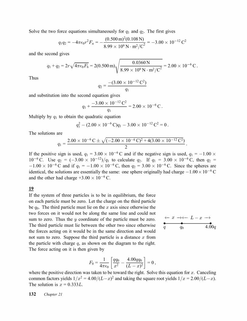
Solve the two force equations simultaneously for q1 and q2. The first gives
q1q2 = ¡4¼²0r2Fa = ¡ (0:500m)2(0:108N)8:99£ 109 N ¢m2=C2 = ¡3:00£ 10
¡12 C2
and the second gives
q1 + q2 = 2rp4¼²0Fb = 2(0:500m)
s0:0360N
8:99£ 109 N ¢m2=C2 = 2:00£ 10¡6 C :
Thusq2 =
¡(3:00£ 10¡12 C2)q1
and substitution into the second equation gives
q1 +¡3:00£ 10¡12 C2
q1= 2:00£ 10¡6 C :
Multiply by q1 to obtain the quadratic equation
q21 ¡ (2:00£ 10¡6 C)q1 ¡ 3:00£ 10¡12 C2 = 0 :The solutions are
q1 =2:00£ 10¡6 C§
p(¡2:00£ 10¡6 C)2 + 4(3:00£ 10¡12 C2)
2:
If the positive sign is used, q1 = 3:00 £ 10¡6 C and if the negative sign is used, q1 = ¡1:00 £10¡6 C. Use q2 = (¡3:00 £ 10¡12)=q1 to calculate q2. If q1 = 3:00 £ 10¡6 C, then q2 =¡1:00 £ 10¡6 C and if q1 = ¡1:00 £ 10¡6 C, then q2 = 3:00 £ 10¡6 C. Since the spheres areidentical, the solutions are essentially the same: one sphere originally had charge ¡1:00£10¡6 Cand the other had charge +3:00£ 10¡6 C.
19If the system of three particles is to be in equilibrium, the forceon each particle must be zero. Let the charge on the third particlebe q0. The third particle must lie on the x axis since otherwise thetwo forces on it would not be along the same line and could notsum to zero. Thus the y coordinate of the particle must be zero.The third particle must lie between the other two since otherwisethe forces acting on it would be in the same direction and wouldnot sum to zero. Suppose the third particle is a distance x fromthe particle with charge q, as shown on the diagram to the right.The force acting on it is then given by
² ²²q 4:00qq0
á x ¡!á L¡ x ¡!
F0 =14¼²0
∙qq0x2¡ 4:00qq0(L¡ x)2
¸= 0 ;
where the positive direction was taken to be toward the right. Solve this equation for x. Cancelingcommon factors yields 1=x2 = 4:00=(L¡x)2 and taking the square root yields 1=x = 2:00=(L¡x).The solution is x = 0:333L.
132 Chapter 21
The force on q is
Fq =14¼²0
∙qq0x2+4:00q2
L2
¸= 0 :
Solve for q0: q0 = ¡4:00qx2=L2 = ¡0:444q, where x = 0:333L was used.The force on the particle with charge 4:00q is
F4q =14¼²0
∙4:00q2
L2+4:00qq0(L¡ x)2
¸=
14¼²0
∙4:00q2
L2+4:00(0:444)q2
(0:444)L2
¸=
14¼²0
∙4:00q2
L2¡ 4:00q
2
L2
¸= 0 :
With q0 = ¡0:444q and x = 0:333L, all three charges are in equilibrium.
25(a) The magnitude of the force between the ions is given by
F =q2
4¼²0r2;
where q is the charge on either of them and r is the distance between them. Solve for the charge:
q = rp4¼²0F = (5:0£ 10¡10 m)
s3:7£ 10¡9 N
8:99£ 109 N ¢m2=C2= 3:2£ 10¡19 C :
(b) Let N be the number of electrons missing from each ion. Then Ne = q and
N =q
e=3:2£ 10¡19 C1:60£ 10¡19 C = 2 :
35(a) Every cesium ion at a corner of the cube exerts a force of the same magnitude on the chlorineion at the cube center. Each force is a force of attraction and is directed toward the cesium ionthat exerts it, along the body diagonal of the cube. We can pair every cesium ion with another,diametrically positioned at the opposite corner of the cube. Since the two ions in such a pairexert forces that have the same magnitude but are oppositely directed, the two forces sum to zeroand, since every cesium ion can be paired in this way, the total force on the chlorine ion is zero.(b) Rather than remove a cesium ion, superpose charge ¡e at the position of one cesium ion.This neutralizes the ion and, as far as the electrical force on the chlorine ion is concerned, it isequivalent to removing the ion. The forces of the eight cesium ions at the cube corners sum tozero, so the only force on the chlorine ion is the force of the added charge.The length of a body diagonal of a cube is
p3a, where a is the length of a cube edge. Thus the
distance from the center of the cube to a corner is d = (p3=2)a. The force has magnitude
F =14¼²0
e2
d2=
14¼²0
e2
(3=4)a2
=(8:99£ 109 N ¢m2=C2)(1:60£ 10¡19 C)2
(3=4)(0:40£ 10¡9 m)2 = 1:9£ 10¡9 N :
Chapter 21 133

Since both the added charge and the chlorine ion are negative, the force is one of repulsion. Thechlorine ion is pulled away from the site of the missing cesium ion.
37None of the reactions given include a beta decay, so the number of protons, the number ofneutrons, and the number of electrons are each conserved. Atomic numbers (numbers of protonsand numbers of electrons) and molar masses (combined numbers of protons and neutrons) canbe found in Appendix F of the text.(a) 1H has 1 proton, 1 electron, and 0 neutrons and 9Be has 4 protons, 4 electrons, and 9¡ 4 = 5neutrons, so X has 1 + 4 = 5 protons, 1 + 4 = 5 electrons, and 0 + 5 ¡ 1 = 4 neutrons. One ofthe neutrons is freed in the reaction. X must be boron with a molar mass of 5 g=mol + 4 g=mol =9 g=mol: 9B.(b) 12C has 6 protons, 6 electrons, and 12¡ 6 = 6 neutrons and 1H has 1 proton, 1 electron, and0 neutrons, so X has 6 + 1 = 7 protons, 6 + 1 = 7 electrons, and 6 + 0 = 6 neutrons. It must benitrogen with a molar mass of 7 g=mol + 6 g=mol = 13 g=mol: 13N.(c) 15N has 7 protons, 7 electrons, and 15 ¡ 7 = 8 neutrons; 1H has 1 proton, 1 electron, and 0neutrons; and 4He has 2 protons, 2 electrons, and 4 ¡ 2 = 2 neutrons; so X has 7 + 1 ¡ 2 = 6protons, 6 electrons, and 8 + 0 ¡ 2 = 6 neutrons. It must be carbon with a molar mass of6 g=mol + 6 g=mol = 12 g=mol: 12C.
39The magnitude of the force of particle 1 on particle 2 is
F =14¼²0
jq1jjq2jd21 + d22
:
The signs of the charges are the same, so the particles repel each other along the line that runsthrough them. This line makes an angle µ with the x axis such that cos µ = d2=
qd21 + d22, so the
x component of the force is
Fx =14¼²0
jq1jjq2jd21 + d22
cos µ =14¼²0
jq1jjq2jd2(d21 + d22)3=2
= (8:99£ 109 C2=N ¢m2) 24(1:60£ 10¡19 C)2(6:00£ 10¡3 m)[(2:00£ 10¡3 m)2 + (6:00£ 10¡3 m)2]3=2 = 1:31£ 10
¡22 N :
50The magnitude of the gravitational force on a proton near Earth’s surface is mg, where m isthe mass of the proton (1:67£ 10¡27 kg from Appendix B). The electrostatic force between twoprotons is F = (1=4¼²0)(e2=d2), where d is their separation. Equate these forces to each otherand solve for d. The result is
d =
s14¼²0
e2
mg=
s(8:99£ 10¡9 N ¢m2=C2) (1:60£ 10¡19 C)2
(1:67£ 10¡27 kg)(9:8m=s2) = 0:119m :
134 Chapter 21

60The magnitude of the force of particle 1 on particle 4 is
F1 =14¼²0
jq1jjq4jd21
= (8:99£109 N ¢m2=C2)(3:20£ 10¡19 C)(3:20£ 10¡19 C)(0:0300m)2
= 1:02£10¡24 N :
The charges have opposite signs, so the particles attract each other and the vector force is
~F1 = ¡(1:02¡24 N)(cos 35:0±) i¡ (1:02£ 10¡24 N)(sin 35:0±) j= ¡(8:36£ 10¡25 N) i¡ (5:85£ 10¡25 N) j :
Particles 2 and 3 repel each other. The force of particle 2 on particle 4 is
~F2 = ¡ 14¼²0
jq2jjq4jd22
j
= ¡(8:99£ 109 N ¢m2=C2)(3:20£ 10¡19 C)(3:20£ 10¡19 C)(0:0200m)2
j = ¡(2:30£ 10¡24 N) j :
Particles 3 and 4 repel each other and the force of particle 3 on particle 4 is
~F3 = ¡ 14¼²0
j2q3jjq4jd23
i
= ¡(8:99£ 109 N ¢m2=C2)(6:40£ 10¡19 C)(3:20£ 10¡19 C)(0:0200m)2
= ¡(4:60£ 10¡24 C) i :
The net force is the vector sum of the three forces. The x component is Fx = ¡18:36£10¡25 N¡4:60N = ¡5:44 £ 10¡24 N and the y component is Fy = ¡5:85 £ 10¡25 N ¡ 2:30 £ 10¡24 N =¡2:89£ 10¡24 N. The magnitude of the force is
F =qF 2x + F 2y =
p(¡5:44£ 10¡24 N)2 + (¡2:89£ 10¡24 N)2 = 6:16£ 1024 N :
The tangent of the angle µ between the net force and the positive x axis is tanµ = Fy=Fx =(¡2:89 £ 10¡24 N)=(¡5:44 £ 10¡24 N) = 0:531 and the angle is either 28± or 208±. The laterangle is associated with a vector that has negative x and y components and so is the correctangle.
69The net force on particle 3 is the vector sum of the forces of particles 1 and 2 and for this tobe zero the two forces must be along the same line. Since electrostatic forces are along the linesthat join the particles, particle 3 must be on the x axis. Its y coordinate is zero.Particle 3 is repelled by one of the other charges and attracted by the other. As a result, particle3 cannot be between the other two particles and must be either to the left of particle 1 or to theright of particle 2. Since the magnitude of q1 is greater than the magnitude of q2, particle 3 must
Chapter 21 135

be closer to particle 2 than to particle 1 and so must be to the right of particle 2. Let x be thecoordinate of particle 3. The the x component of the force on it is
Fx =14¼²0
hq1q3x2
+q2q3
(x¡ L)2i:
If Fx = 0 the solution for x is
x =p¡q1=q2p¡q1=q2 ¡ 1L =
p¡(¡5:00q)=(2:00q)p¡(¡5:00q)=(2:00q)¡ 1L = 2:72L :
136 Chapter 21

Chapter 22
3Since the magnitude of the electric field produced by a point particle with charge q is givenby E = jqj=4¼²0r2, where r is the distance from the particle to the point where the field hasmagnitude E, the magnitude of the charge is
jqj = 4¼²0r2E = (0:50m)2(2:0N=C)8:99£ 109 N ¢m2=C2 = 5:6£ 10
¡11 C :
5Since the charge is uniformly distributed throughout a sphere, the electric field at the surface isexactly the same as it would be if the charge were all at the center. That is, the magnitude of thefield is
E =q
4¼²0R2;
where q is the magnitude of the total charge and R is the sphere radius. The magnitude of thetotal charge is Ze, so
E =Ze
4¼²0R2=(8:99£ 109 N ¢m2=C2)(94)(1:60£ 10¡19 C)
(6:64£ 10¡15 m)2 = 3:07£ 1021 N=C :
The field is normal to the surface and since the charge is positive it points outward from thesurface.
9Choose the coordinate axes as shown on the diagramto the right. At the center of the square, the electricfields produced by the particles at the lower left andupper right corners are both along the x axis and eachpoints away from the center and toward the particlethat produces it. Since each particle is a distance d =p2a=2 = a=
p2 away from the center, the net field due
to these two particles is
Ex =14¼²0
∙2qa2=2
¡ q
a2=2
¸ ²
²
²
²
..........................................................................................................................................................................................................................................................................................................
................................................................................................................................................................................................................................................................................
d
d
a
a
xy
¡q
q ¡2q
2q
=14¼²0
q
a2=2=(8:99£ 109 N ¢m2=C2)(1:0£ 10¡8 C)
(0:050m)2=2= 7:19£ 104 N=C.
Chapter 22 137

At the center of the square, the field produced by the particles at the upper left and lower rightcorners are both along the y axis and each points away from the particle that produces it. Thenet field produced at the center by these particles is
Ey =14¼²0
∙2qa2=2
¡ q
a2=2
¸=
14¼²0
q
a2=2= 7:19£ 104 N=C :
The magnitude of the net field is
E =qE2x + E2y =
q2(7:19£ 104 N=C)2 = 1:02£ 105 N=C
and the angle it makes with the x axis is
µ = tan¡1EyEx
= tan¡1(1) = 45± :
It is upward in the diagram, from the center of the square toward the center of the upper side.
21Think of the quadrupole as composed of two dipoles, each with dipole moment of magnitudep = qd. The moments point in opposite directions and produce fields in opposite directions atpoints on the quadrupole axis. Consider the point P on the axis, a distance z to the right of thequadrupole center and take a rightward pointing field to be positive. Then the field producedby the right dipole of the pair is qd=2¼²0(z ¡ d=2)3 and the field produced by the left dipoleis ¡qd=2¼²0(z + d=2)3. Use the binomial expansions (z ¡ d=2)¡3 ¼ z¡3 ¡ 3z¡4(¡d=2) and(z + d=2)¡3 ¼ z¡3 ¡ 3z¡4(d=2) to obtain
E =qd
2¼²0
∙1z3+3d2z4
¡ 1z3+3d2z4
¸=6qd2
4¼²0z4:
Let Q = 2qd2. ThenE =
3Q4¼²0z4
:
27(a) The linear charge density ¸ is the charge per unit length of rod. Since the charge is uniformlydistributed on the rod, ¸ = ¡q=L = ¡(4:23£ 10¡15 C)=(0:0815m) = ¡5:19£ 10¡14 C=m.(b) and (c) Position the origin at the left end ofthe rod, as shown in the diagram. Let dx be aninfinitesimal length of rod at x. The charge inthis segment is dq = ¸ dx. Since the segmentmay be taken to be a point particle, the elec-tric field it produces at point P has only an xcomponent and this component is given by
dx²P
0 x L L + a
dEx =14¼²0
¸ dx(L + a¡ x)2 :
138 Chapter 22

The total electric field produced at P by the whole rod is the integral
Ex =¸
4¼²0
Z L
0
dx(L + a¡ x)2 =
¸
4¼²01
L + a¡ x¯L0
=¸
4¼²0
∙1a¡ 1L + a
¸=
¸
4¼²0L
a(L + a):
When ¡q=L is substituted for ¸ the result is
Ex = ¡ 14¼²0
q
a(L + a)= ¡(8:99£ 10
9 N ¢m2=C2)(4:23£ 10¡15 C)(0:120m)(0:0815m + 0:120m)
= ¡1:57£ 10¡3 N=C :
The negative sign indicates that the field is toward the rod and makes an angle of 180± with thepositive x direction.(d) Now
Ex = ¡ 14¼²0
q
a(L + a)= ¡(8:99£ 10
9 N ¢m2=C2)(4:23£ 10¡15 C)(50m)(0:0815m + 50m)
= ¡1:52£ 10¡8 N=C :
(e) The field of a point particle at the origin is
Ex = ¡ q
4¼²0a2= ¡(8:99£ 10
9 N ¢m2=C2)(4:23£ 10¡15 C)(50m)2
= ¡1:52£ 10¡8 N=C :
35At a point on the axis of a uniformly charged disk a distance z above the center of the disk, themagnitude of the electric field is
E =¾
2²0
∙1¡ zp
z2 +R2
¸;
where R is the radius of the disk and ¾ is the surface charge density on the disk. See Eq. 22–26.The magnitude of the field at the center of the disk (z = 0) is Ec = ¾=2²0. You want to solvefor the value of z such that E=Ec = 1=2. This means
E
Ec= 1¡ zp
z2 +R2=12
orzp
z2 +R2=12:
Square both sides, then multiply them by z2 +R2 to obtain z2 = (z2=4)+(R2=4). Thus z2 = R2=3and z = R=
p3 = (0:600m)=
p3 = 0:346m.
39The magnitude of the force acting on the electron is F = eE, where E is the magnitude of theelectric field at its location. The acceleration of the electron is given by Newton’s second law:
a =F
m=eE
m=(1:60£ 10¡19 C)(2:00£ 104 N=C)
9:11£ 10¡31 kg = 3:51£ 1015 m=s2 :
Chapter 22 139

43(a) The magnitude of the force on the particle is given by F = qE, where q is the magnitude ofthe charge carried by the particle and E is the magnitude of the electric field at the location ofthe particle. Thus
E =F
q=3:0£ 10¡6 N2:0£ 10¡9 C = 1:5£ 10
3 N=C :
The force points downward and the charge is negative, so the field points upward.(b) The magnitude of the electrostatic force on a proton is
Fe = eE = (1:60£ 10¡19 C)(1:5£ 103 N=C) = 2:4£ 10¡16 N :(c) A proton is positively charged, so the force is in the same direction as the field, upward.(d) The magnitude of the gravitational force on the proton is
Fg = mg = (1:67£ 10¡27 kg)(9:8m=s2) = 1:64£ 10¡26 N :The force is downward.(e) The ratio of the force magnitudes is
FeFg=2:4£ 10¡16 N1:64£ 10¡26 N = 1:5£ 10
10 :
45(a) The magnitude of the force acting on the proton is F = eE, where E is the magnitude of theelectric field. According to Newton’s second law, the acceleration of the proton is a = F=m =eE=m, where m is the mass of the proton. Thus
a =(1:60£ 10¡19 C)(2:00£ 104 N=C)
1:67£ 10¡27 kg = 1:92£ 1012 m=s2 :
(b) Assume the proton starts from rest and use the kinematic equation v2 = v20 + 2ax (or elsex = 1
2at2 and v = at) to show that
v =p2ax =
q2(1:92£ 1012 m=s2)(0:0100m) = 1:96£ 105 m=s :
57(a) If q is the positive charge in the dipole and d is the separation of the charged particles, themagnitude of the dipole moment is p = qd = (1:50£10¡9 C)(6:20£10¡6 m) = 9:30£10¡15 C ¢m.(b) If the initial angle between the dipole moment and the electric field is µ0 and the final angleis µ, then the change in the potential energy as the dipole swings from µ = 0 to µ = 180± is
¢U = ¡pE(cos µ ¡ cos µ0) = ¡(9:30£ 10¡15 C ¢m)(1100N=C)(cos 180± ¡ cos 0)= 2:05£ 10¡11 J :
140 Chapter 22

79(a) and (b) Since the field at the point on the x axis with coordinate x = 2:0 cm is in the positivex direction you know that the charged particle is on the x axis. The line through the pointwith coordinates x = 3:0 cm and y = 3:0 cm and parallel to the field at that point must passthrough the position of the particle. Such a line has slope (3:0)=(4:0) = 0:75 and its equation isy = 0:57 + (0:75)x. The solution for y = 0 is x = ¡1:0 cm, so the particle is located at the pointwith coordinates x = ¡1:0 cm and y = 0.(c) The magnitude of the field at the point on the x axis with coordinate x = 2:0 cm is given byE = (1=4¼²0)q=(2:0 cm¡ x)2, so
q = 4¼²0x2E =(0:020m + 0:010m)2(100N=C)
8:99£ 109 N ¢m2=C2= 1:0£ 10¡11 C :
81
(a) The potential energy of an electric dipole with dipole moment ~p in an electric field ~E is
U = ¡~p ¢ ~E = (1:24£ 10¡30 C ¢m)(3:00 i + 4:00 j) ¢ (4000N=C) i= ¡(1:24£ 10¡30 C ¢m)(3:00)(4000N=C) = ¡1:49£ 10¡26 J :
Here we used ~a ¢~b = axbx + ayby + azbz to evaluate the scalar product.(b) The torque is
~¿ = ~p£ ~E = (px i + py j)£ (Ex i) = ¡pyEx k= ¡(4:00)(1:24£ 10¡30 C ¢m)(4000N=C) = ¡(1:98£ 10¡26 N ¢m) k :
(c) The work done by the agent is equal to the change in the potential energy of the dipole. Theinitial potential energy is Ui = ¡1:49 £ 10¡26 J, as computed in part (a). The final potentialenergy is
Uf = (1:24£ 10¡30 C ¢m)(¡4:00 i + 3:00 j) ¢ (4000N=C) i= ¡(1:24£ 10¡30 C ¢m)(¡4:00)(4000N=C) = +1:98£ 10¡26 J :
The work done by the agent is W = (1:98£ 10¡26 J)¡ (¡1:49£ 10¡26 J) = 3:47£ 10¡26 J.
Chapter 22 141

Chapter 23
1
The vector area ~A and the electric field ~E are shown on the dia-gram to the right. The angle µ between them is 180± ¡ 35± = 145±,so the electric flux through the area is © = ~E ¢ ~A = EA cos µ =(1800N=C)(3:2£ 10¡3 m)2 cos 145± = ¡1:5£ 10¡2 N ¢m2=C.
.......
.......
.......
.......
.......
.......
.......
.......
.......
.......
.......
.......
.......
.......
.......
..........................
......................
.......................................................................................................................................................................
......................
...........................................................................................
..........................................................................................................................................
µ
A
E
35±
9Let A be the area of one face of the cube, Eu be the magnitude of the electric field at the upperface, and E` be the magnitude of the field at the lower face. Since the field is downward, theflux through the upper face is negative and the flux through the lower face is positive. The fluxthrough the other faces is zero, so the total flux through the cube surface is © = A(E` ¡ Eu).The net charge inside the cube is given by Gauss’ law:
q = ²0© = ²0A(E` ¡Eu) = (8:85£ 10¡12 C2=N ¢m2)(100m)2(100N=C¡ 60:0N=C)= 3:54£ 10¡6 C = 3:54¹C :
19(a) The charge on the surface of the sphere is the product of the surface charge density ¾ andthe surface area of the sphere (4¼r2, where r is the radius). Thus
q = 4¼r2¾ = 4¼µ1:2m2
¶2(8:1£ 10¡6 C=m2) = 3:7£ 10¡5 C :
(b) Choose a Gaussian surface in the form a sphere, concentric with the conducting sphere andwith a slightly larger radius. The flux through the surface is given by Gauss’ law:
© =q
²0=
3:7£ 10¡5 C8:85£ 10¡12 C2=N ¢m2 = 4:1£ 10
6 N ¢m2=C :
23The magnitude of the electric field produced by a uniformly charged infinite line is E = ¸=2¼²0r,where ¸ is the linear charge density and r is the distance from the line to the point where thefield is measured. See Eq. 23–12. Thus
¸ = 2¼²0Er = 2¼(8:85£ 10¡12 C2=N ¢m2)(4:5£ 104 N=C)(2:0m) = 5:0£ 10¡6 C=m :142 Chapter 23

27Assume the charge density of both the conducting rod and the shell are uniform. Neglect fringing.Symmetry can be used to show that the electric field is radial, both between the rod and the shelland outside the shell. It is zero, of course, inside the rod and inside the shell since they areconductors.(a) and (b) Take the Gaussian surface to be a cylinder of length L and radius r, concentricwith the conducting rod and shell and with its curved surface outside the shell. The area of thecurved surface is 2¼rL. The field is normal to the curved portion of the surface and has uniformmagnitude over it, so the flux through this portion of the surface is © = 2¼rLE, where E is themagnitude of the field at the Gaussian surface. The flux through the ends is zero. The chargeenclosed by the Gaussian surface is Q1 ¡ 2:00Q1 = ¡Q1. Gauss’ law yields 2¼r²0LE = ¡Q1,so
E = ¡ Q12¼²0Lr
= ¡(8:99£ 109N ¢m2=C2)(3:40£ 10¡12 C)
(11:00m)(26:0£ 10¡3 m) = ¡0:214N=C :
The magnitude of the field is 0:214N=C. The negative sign indicates that the field points inward.(c) and (d) Take the Gaussian surface to be a cylinder of length L and radius r, concentric withthe conducting rod and shell and with its curved surface between the conducting rod and theshell. As in (a), the flux through the curved portion of the surface is © = 2¼rLE, where E isthe magnitude of the field at the Gaussian surface, and the flux through the ends is zero. Thecharge enclosed by the Gaussian surface is only the charge Q1 on the conducting rod. Gauss’law yields 2¼²0rLE = Q1, so
E =Q1
2¼²0Lr=2(8:99£ 109 N ¢m2=C2)(3:40£ 10¡12 C)
(11:00m)(6:50£ 10¡3 m) = +0:855N=C :
The positive sign indicates that the field points outward.(e) Consider a Gaussian surface in the form of a cylinder of length L with the curved portionof its surface completely within the shell. The electric field is zero at all points on the curvedsurface and is parallel to the ends, so the total electric flux through the Gaussian surface is zeroand the net charge within it is zero. Since the conducting rod, which is inside the Gaussiancylinder, has charge Q1, the inner surface of the shell must have charge ¡Q1 = ¡3:40£10¡12 C.(f) Since the shell has total charge ¡2:00Q1 and has charge ¡Q1 on its inner surface, it musthave charge ¡Q1 = ¡3:40£ 10¡12 C on its outer surface.
35(a) To calculate the electric field at a point very close to the center of a large, uniformly chargedconducting plate, we may replace the finite plate with an infinite plate with the same area chargedensity and take the magnitude of the field to be E = ¾=²0, where ¾ is the area charge densityfor the surface just under the point. The charge is distributed uniformly over both sides of theoriginal plate, with half being on the side near the field point. Thus
¾ =q
2A=6:0£ 10¡6 C2(0:080m)2
= 4:69£ 10¡4 C=m2 :
Chapter 23 143

The magnitude of the field is
E =¾
²0=
4:69£ 10¡4 C=m28:85£ 10¡12 C2=N ¢m2 = 5:3£ 10
7 N=C :
The field is normal to the plate and since the charge on the plate is positive, it points away fromthe plate.(b) At a point far away from the plate, the electric field is nearly that of a point particle withcharge equal to the total charge on the plate. The magnitude of the field is E = q=4¼²0r2, wherer is the distance from the plate. Thus
E =(8:99£ 109 N ¢m2=C2)(6:0£ 10¡6 C)
(30m)2= 60N=C :
41The forces on the ball are shown in the diagram to the right. The grav-itational force has magnitude mg, where m is the mass of the ball; theelectrical force has magnitude qE, where q is the charge on the ball andE is the electric field at the position of the ball; and the tension in thethread is denoted by T . The electric field produced by the plate is normalto the plate and points to the right. Since the ball is positively charged,the electric force on it also points to the right. The tension in the threadmakes the angle µ (= 30±) with the vertical.
²..................................................................................... ......................
...................................................................................................................................
......................
..........................................................................................................................................................................T
qE
mg
µ
Since the ball is in equilibrium the net force on it vanishes. The sum of the horizontal componentsyields qE ¡ T sin µ = 0 and the sum of the vertical components yields T cos µ ¡ mg = 0.The expression T = qE= sin µ, from the first equation, is substituted into the second to obtainqE = mg tan µ.The electric field produced by a large uniform plane of charge is given by E = ¾=2²0, where ¾is the surface charge density. Thus
q¾
2²0= mg tan µ
and¾ =
2²0mg tan µq
=2(8:85£ 10¡12 C2=N ¢m2)(1:0£ 10¡6 kg)(9:8m=s2) tan 30±
2:0£ 10¡8 C= 5:0£ 10¡9 C=m2 :
45Charge is distributed uniformly over the surface of the sphere and the electric field it produces atpoints outside the sphere is like the field of a point particle with charge equal to the net chargeon the sphere. That is, the magnitude of the field is given by E = q=4¼²0r2, where q is the
144 Chapter 23

magnitude of the charge on the sphere and r is the distance from the center of the sphere to thepoint where the field is measured. Thus
q = 4¼²0r2E =(0:15m)2(3:0£ 103 N=C)8:99£ 109 N ¢m2=C2
= 7:5£ 10¡9 C :
The field points inward, toward the sphere center, so the charge is negative: ¡7:5£ 10¡9 C.
49To find an expression for the electric field inside the shell in terms of A and the distance fromthe center of the shell, select A so the field does not depend on the distance.Use a Gaussian surface in the form of a sphere with radius rg, concentric with the sphericalshell and within it (a < rg < b). Gauss’ law is used to find the magnitude of the electric field adistance rg from the shell center.The charge that is both in the shell and within the Gaussian sphere is given by the integralqenc =
R½ dV over the portion of the shell within the Gaussian surface. Since the charge
distribution has spherical symmetry, we may take dV to be the volume of a spherical shell withradius r and infinitesimal thickness dr: dV = 4¼r2 dr. Thus
qenc = 4¼Z rg
a
½r2 dr = 4¼Z rg
a
A
rr2 dr = 4¼A
Z rg
a
r dr = 2¼A(r2g ¡ a2) :
The total charge inside the Gaussian surface is q + qenc = q + 2¼A(r2g ¡ a2).The electric field is radial, so the flux through the Gaussian surface is © = 4¼r2gE, where E isthe magnitude of the field. Gauss’ law yields
4¼²0Er2g = q + 2¼A(r2g ¡ a2) :Solve for E:
E =14¼²0
∙q
r2g+ 2¼A¡ 2¼Aa
2
r2g
¸:
For the field to be uniform, the first and last terms in the brackets must cancel. They do ifq ¡ 2¼Aa2 = 0 or A = q=2¼a2 = (45:0£ 10¡15 C)=2¼(2:00£ 10¡2 m)2 = 1:79£ 10¡11 C=m2.
59(a) The magnitude E1 of the electric field produced by the charge q on the spherical shell isE1 = q=4¼²0R2o, where Ro is the radius of the outer surface of the shell. Thus
q = 4¼²0E1R2o =(450N=C)(0:20m)2
8:99£ 109 N ¢m2=C2 = 2:0£ 10¡9 C :
(b) Since the field at P is outward and is reduced in magnitude the field of Q must be inward. Qis a negative charge and the magnitude of its field at P is E2 = 450N=C¡ 180N=C = 270N=C.The value of Q is
Q = 4¼²0E2R2o = ¡(270N=C)(0:20m)2
8:99£ 109 N ¢m2=C)2 = ¡1:2£ 10¡9 C :
Chapter 23 145

(c) Gauss’ law tells us that since the electric field is zero inside a conductor the net charge insidea spherical surface with a radius that is slightly larger than the inside radius of the shell must bezero. Thus the charge on the inside surface of the shell is +1:2£ 10¡9 C.(d) The remaining charge on the shell must be on its outer surface and this is 2:0 £ 10¡9 C ¡1:2£ 10¡9 C = +0:8£ 10¡9 C.
69(a) Draw a spherical Gaussian surface with radius r, concentric with the shells. The electricfield, if it exists, is radial and so is normal to the surface. The integral in Gauss’ law isH~E ¢d ~A = 4¼r2E, where E is the radial component of the field. For r < a then charge enclosed
is zero. Gauss’ law gives 4¼r2E = 0, so E = 0.(b) For a < r < b the charge enclosed by the Gaussian surface is qa, so the law gives 4¼r2E =qa=²0 and E = qa=4¼²0r2.(c) For r > b the charge enclosed by the Gaussian surface is qa + qb, so 4¼²0E = (qa + qb)=²0and E = (qa + qb)=4¼²0r2.(d) Consider first a spherical Gaussian with radius just slightly greater than a. The electric fieldis zero everywhere on this surface, so according to Gauss’ law it encloses zero net charge. Sincethere is no charge in the cavity the charge on the inner surface of the smaller shell is zero. Thetotal charge on the smaller shell is qa and this must reside on the outer surface. Now consider aspherical Gaussian surface with radius slight larger than the inner radius of the larger shell. Thissurface also encloses zero net charge, which is the sum of the charge on the outer surface of thesmaller shell and the charge on the inner surface of the larger shell. Thus the charge on the innersurface of the larger shell is ¡qa. The net charge on the larger shell is qb, with ¡qa on its innersurface, so the charge on its outer surface must be qb ¡ (¡qa) = qb + qa.
76(a) The magnitude of the electric field due to a large uniformly charged plate is given by ¾=2²0,where ¾ is the surface charge density. In the region between the oppositely charged plates thefields of the plates are in the same direction, so the net field has magnitude E = ¾=²0. Theelectrical force on an electron has magnitude eE = e¾=²0 and the gravitational force on it ismg, where m is it mass. If these forces are to balance, they must have the same magnitude, somg = e¾=²0 and
¾ =mg²0e
=(9:11£ 10¡31 kg)(9:8m=s2)(8:85£ 10¡12 C2=N ¢m2)
1:60£ 10¡19 C = 4:9£ 10¡22 C=m2 :
(b) The gravitational force is downward, so the electrical force must be upward. Since an electronis negatively charged the electrical force on it is opposite to the electric field, so the electric fieldmust be downward.
79(a) Let Q be the net charge on the shell, qi be the charge on its inner surface and qo be the chargeon its outer surface. Then Q = qi + qo and qi = Q¡ qo = (¡10¹C)¡ (¡14¹C) = +4¹C.146 Chapter 23

(b) Let q be the charge on the particle. Gauss’ law tells us that since the electric field is zeroinside the conducting shell the net charge inside any spherical surface that entirely within theshell is zero. Thus the sum of the charge on the particle and on the inner surface of the shell iszero, so q + qi = 0 and q = ¡qi = ¡4¹C.
Chapter 23 147

Chapter 24
3(a) An ampere is a coulomb per second, so
84A ¢ h =µ84C ¢ hs
¶³3600
sh
´= 3:0£ 105 C :
(b) The change in potential energy is ¢U = q¢V = (3:0£ 105 C)(12V) = 3:6£ 106 J.
5The electric field produced by an infinite sheet of charge has magnitude E = ¾=2²0, where ¾ isthe surface charge density. The field is normal to the sheet and is uniform. Place the origin of acoordinate system at the sheet and take the x axis to be parallel to the field and positive in thedirection of the field. Then the electric potential is
V = Vs ¡Z x
0E dx = Vs ¡Ex ;
where Vs is the potential at the sheet. The equipotential surfaces are surfaces of constant x; thatis, they are planes that are parallel to the plane of charge. If two surfaces are separated by ¢xthen their potentials differ in magnitude by ¢V = E¢x = (¾=2²0)¢x. Thus
¢x =2²0¢V¾
=2(8:85£ 10¡12 C2=N ¢m2)(50V)
0:10£ 10¡6 C=m2 = 8:8£ 10¡3 m :
19(a) The electric potential V at the surface of the drop, the charge q on the drop, and the radiusR of the drop are related by V = q=4¼²0R. Thus
R =q
4¼²0V=(8:99£ 109 N ¢m2=C2)(30£ 10¡12 C)
500V= 5:4£ 10¡4 m :
(b) After the drops combine the total volume is twice the volume of an original drop, so theradius R0 of the combined drop is given by (R0)3 = 2R3 and R0 = 21=3R. The charge is twicethe charge of original drop: q0 = 2q. Thus
V 0 =14¼²0
q0
R0=
14¼²0
2q21=3R
= 22=3V = 22=3(500V) = 790V :
29The disk is uniformly charged. This means that when the full disk is present each quadrantcontributes equally to the electric potential at P , so the potential at P due to a single quadrantis one-fourth the potential due to the entire disk. First find an expression for the potential at Pdue to the entire disk.
148 Chapter 24

Consider a ring of charge with radius r and width dr. Its area is 2¼r dr and it contains chargedq = 2¼¾r dr. All the charge in it is a distance
pr2 +D2 from P , so the potential it produces
at P isdV =
14¼²0
2¼¾r drpr2 +D2
=¾r dr
2²0pr2 +D2
:
The total potential at P is
V =¾
2²0
Z R
0
r drpr2 +D2
=¾
2²0
pr2 +D2
¯R0=¾
2²0
hpR2 +D2 ¡D
i:
The potential Vsq at P due to a single quadrant is
Vsq =V
4=¾
8²0
hpR2 +D2 ¡D
i=
7:73£ 10¡15 C=m28(8:85£ 10¡12 C2=N ¢m2)
hp(0:640m)2 + (0:259m)2 ¡ 0:259m
i= 4:71£ 10¡5 V :
39Take the negatives of the partial derivatives of the electric potential with respect to the coordinatesand evaluate the results for x = 3:00m, y = ¡2:00m, and z = 4:00m. This yields
Ex = ¡@V@x
= ¡(2:00V=m4)yz2 = ¡(2:00V=m4)((¡2:00m)(4:00m)2 = 64:0V=m ;
Ey = ¡@V@y
= ¡(2:00V=m4)xz2 = ¡(2:00V=m4)(3:00m)(4:00m)2 = ¡96:0V=m ;
Ez = ¡@V@z
= ¡2(2:00V=m4)xyz = ¡2(2:00V=m4)(3:00m)(¡2:00m)(4:00m) = 96:0V=m :
The magnitude of the electric field is
E =qE2x + E2y + E2z =
q(64:0V=m)2 + (¡96:0V=m)2 + (96:0V=m)2 = 1:50£ 102 V=m :
41The work required is equal to the potential energy of the system, relative to a potential energy ofzero for infinite separation. Number the particles 1, 2, 3, and 4, in clockwise order starting withthe particle in the upper left corner of the arrangement. The potential energy of the interactionof particles 1 and 2 is
U12 =q1q24¼²0a
=(8:99£ 109 N ¢m2=C2)(2:30£ 10¡12 C)(¡2:30£ 10¡12 C)
0:640m= ¡7:43£ 10¡14 J :
The distance between particles 1 and 3 isp2a and both these particles are positively charged,
so the potential energy of the interaction between particles 1 and 3 is U13 = ¡U12=p2 = +5:25£
Chapter 24 149

10¡14 J. The potential energy of the interaction between particles 1 and 4 is U14 = U12 =¡7:43 £ 10¡14 J. The potential energy of the interaction between particles 2 and 3 is U23 =U12 = ¡7:43 £ 10¡14 J. The potential energy of the interaction between particles 2 and 4 isU24 = U13 = 5:25£ 10¡14 J. The potential energy of the interaction between particles 3 and 4 isU34 = U12 = ¡7:43£ 10¡14 J.The total potential energy of the system is
U = U12 + U13 + U14 + U23 + U24 + U34= ¡7:43£ 10¡14 J + 5:25£ 10¡14 J¡ 7:43£ 10¡14 J¡ 7:43£ 10¡14 J
¡ 7:43£ 10¡14 J + 5:25£ 10¡14 J = ¡1:92£ 10¡13 J :This is equal to the work that must be done to assemble the system from infinite separation.
59(a) Use conservation of mechanical energy. The potential energy when the moving particle is atany coordinate y is qV , where V is the electric potential produced at that place by the two fixedparticles. That is,
U = q2Q
4¼²0px2 + y2
;
where x is the coordinate and Q is the charge of either one of the fixed particles. The factor2 appears since the two fixed particles produce the same potential at points on the y axis.Conservation of mechanical energy yields
Kf = Ki + q2Q
4¼²0px2 + y2i
¡ q 2Q
4¼²0qx2 + y2f
= Ki +2qQ4¼²0
0@ 1px2 + y2i
¡ 1qx2 + y2f
1A ;
where K is the kinetic energy of the moving particle, the subscript i refers to the initial positionof the moving particle, and the subscript f refers to the final position. Numerically
Kf = 1:2 J +2(¡15£ 10¡6 C)(50£ 10¡6 C)4¼(8:85£ 10¡12 C2=N ¢m2)
"1p
(3:0m)2 + (4:0m)2¡ 1p
(3:0m)2
#= 3:0 J :
(b) Now Kf = 0 and we solve the energy conservation equation for yf . Conservation of energyfirst yields Uf = Ki + Ui. The initial potential energy is
Ui =2qQ
4¼²0px2 + y2i
=2(¡15£ 10¡6 C)(50£ 10¡6 C)
4¼(8:85£ 10¡12 C2=N ¢m2)p(3:0m)2 + (4:0m)2
= ¡2:7 J :
Thus Kf = 1:2 J¡ 2:7 J = ¡1:5 J.Now
Uf =2qQ
4¼²0qx2 + y2f
150 Chapter 24

so
y = ¡sµ
2qQ4¼²0Uf
¶2¡ x2 =
sµ2(¡15£ 10¡6 C)(50£ 10¡6 C)
4¼(8:85£ 10¡12 C2=N ¢m2)(¡1:5 J)¶2¡ (3:0m)2 = ¡8:5m :
63If the electric potential is zero at infinity, then the electric potential at the surface of the sphereis given by V = q=4¼²0r, where q is the charge on the sphere and r is its radius. Thus
q = 4¼²0rV =(0:15m)(1500V)
8:99£ 109 N ¢m2=C2 = 2:5£ 10¡8 C :
65(a) The electric potential is the sum of the contributions of the individual spheres. Let q1 bethe charge on one, q2 be the charge on the other, and d be their separation. The point halfwaybetween them is the same distance d=2 (= 1:0m) from the center of each sphere, so the potentialat the halfway point is
V =q1 + q24¼²0d=2
=(8:99£ 109 N ¢m2=C2)(1:0£ 10¡8 C¡ 3:0£ 10¡8 C)
1:0m= ¡1:80£ 102 V :
(b) The distance from the center of one sphere to the surface of the other is d¡ R, where R isthe radius of either sphere. The potential of either one of the spheres is due to the charge on thatsphere and the charge on the other sphere. The potential at the surface of sphere 1 is
V1 =14¼²0
∙q1R+
q2d¡R
¸= (8:99£ 109 N ¢m2=C2)
∙1:0£ 10¡8 C0:030m
¡ 3:0£ 10¡8 C2:0m¡ 0:030m
¸= 2:9£ 103 V :
(c) The potential at the surface of sphere 2 is
V2 =14¼²0
∙q1
d¡R +q2R
¸= (8:99£ 109 N ¢m2=C2)
∙1:0£ 10¡8 C2:0m¡ 0:030m ¡
3:0£ 10¡8 C0:030m
¸= ¡8:9£ 103 V :
75The initial potential energy of the three-particle system is Ui = 2(q2=4¼²0L) + Ufixed, where q isthe charge on each particle, L is the length of a triangle side, and Ufixed is the potential energyassociated with the interaction of the two fixed particles. The factor 2 appears since the potential
Chapter 24 151

energy is the same for the interaction of the movable particle and each of the fixed particles. Thefinal potential energy is Uf = 2[q2=4¼²0(L=2)] + Ufixed and the change in the potential energy is
¢U = Uf ¡ Ui = 2q2
4¼²0
µ2L¡ 1L
¶=2q2
4¼²0L:
This is the work that is done by the external agent. If P is the rate with energy is supplied bythe agent and t is the time for the move, then Pt = ¢U , and
t =¢U
P=
2q2
4¼²0LP=2(8:99£ 109 N ¢m2=C2)(0:12C)2
(1:7m)(0:83£ 103 W) = 1:83£ 105 s :
This is 2:1 d.
77(a) Use Gauss’ law to find an expression for the electric field. The Gaussian surface is acylindrical surface that is concentric with the cylinder and has a radius r that is greater thanthe radius of the cylinder. The electric field is normal to the Gaussian surface and has uniformmagnitude on it, so the integral in Gauss’ law is
H~E ¢ d ~A = 2¼rEL, where L is the length of
the Gaussian surface. The charge enclosed is ¸L, where ¸ is the charge per unit length on thecylinder. Thus 2¼rRLE = ¸L=²0 and E = ¸=2¼²0r.Let EB be the magnitude of the field at B and rB be the distance from the central axis to B. LetEC be the magnitude of the field at C and rC be the distance from the central axis to C. SinceE is inversely proportional to the distance from the central axis,
EC =rBrCEB =
2:0 cm5:0 cm
(160N=C) = 64N=C :
(b) The magnitude of the field a distance r from the central axis is E = (rB=r)EB , so thepotential difference of points B and C is
VB ¡ VC = ¡Z rB
rC
rBrEB dr = ¡rBEB ln
µrBrC
¶= ¡(0:020m)(160N=C) ln
µ0:020m0:050m
¶= 2:9V :
(c) The cylinder is conducting, so all points inside have the same potential, namely VB , soVA ¡ VB = 0.
85Consider a point on the z axis that has coordinate z. All points on the ring are the same distancefrom the point. The distance is r =
pR2 + z2, where R is the radius of the ring. If the electric
potential is taken to be zero at points that are infinitely far from the ring, then the potential atthe point is
V =Q
4¼²0pR2 + z2
;
152 Chapter 24

where Q is the charge on the ring. Thus
VB ¡ VA = Q
4¼²0
∙1p
R2 + z2¡ 1R
¸= (8:99£ 109 N ¢m2=C2)(16:0£ 10¡6 C)
"1p
(0:0300m)2 + (0:0400m)2¡ 0:300m
#= ¡1:92£ 106 V :
93(a) For r > r2 the field is like that of a point charge and
V =14¼²0
Q
r;
where the zero of potential was taken to be at infinity.(b) To find the potential in the region r1 < r < r2, first use Gauss’s law to find an expressionfor the electric field, then integrate along a radial path from r2 to r. The Gaussian surface isa sphere of radius r, concentric with the shell. The field is radial and therefore normal to thesurface. Its magnitude is uniform over the surface, so the flux through the surface is © = 4¼r2E.The volume of the shell is (4¼=3)(r32 ¡ r31), so the charge density is
½ =3Q
4¼(r32 ¡ r31)and the charge enclosed by the Gaussian surface is
q =µ4¼3
¶(r3 ¡ r31)½ = Q
µr3 ¡ r31r32 ¡ r31
¶:
Gauss’ law yields
4¼²0r2E = Qµr3 ¡ r31r32 ¡ r31
¶and the magnitude of the electric field is
E =Q
4¼²0r3 ¡ r31
r2(r32 ¡ r31):
If Vs is the electric potential at the outer surface of the shell (r = r2) then the potential a distancer from the center is given by
V = Vs ¡Z r
r2
E dr = Vs ¡ Q
4¼²01
r32 ¡ r31
Z r
r2
µr ¡ r
31r2
¶dr
= Vs ¡ Q
4¼²01
r32 ¡ r31
µr2
2¡ r
222+r31r¡ r
31r2
¶:
Chapter 24 153

The potential at the outer surface is found by placing r = r2 in the expression found in part (a).It is Vs = Q=4¼²0r2. Make this substitution and collect like terms to find
V =Q
4¼²01
r32 ¡ r31
µ3r222¡ r
2
2¡ r
31r
¶:
Since ½ = 3Q=4¼(r32 ¡ r31) this can also be written
V =½
3²0
µ3r222¡ r
2
2¡ r
31r
¶:
(c) The electric field vanishes in the cavity, so the potential is everywhere the same inside andhas the same value as at a point on the inside surface of the shell. Put r = r1 in the result of part(b). After collecting terms the result is
V =Q
4¼²03(r22 ¡ r21)2(r32 ¡ r31)
;
or in terms of the charge densityV =
½
2²0(r22 ¡ r21) :
(d) The solutions agree at r = r1 and at r = r2.
95The electric potential of a dipole at a point a distance r away is given by Eq. 24–30:
V =14¼²0
p cos µr2
;
where p is the magnitude of the dipole moment and µ is the angle between the dipole momentand the position vector of the point. The potential at infinity was taken to be zero. Take the zaxis to be the dipole axis and consider a point with z positive (on the positive side of the dipole).For this point r = z and µ = 0. The z component of the electric field is
Ez = ¡@V@x
= ¡@@z
µp
4¼²0z2
¶=
p
2¼²0z3:
This is the only nonvanishing component at a point on the dipole axis.For a point with a negative value of z, r = ¡z and cos µ = ¡1, so
Ez = ¡@@z
µ ¡p4¼²0z2
¶= ¡ p
2¼²0z3:
103(a) The electric potential at the surface of the sphere is given by V = q=4¼²0R, where q is thecharge on the sphere and R is the sphere radius. The charge on the sphere when the potentialreaches 1000V is
q = 4¼²0rV =(0:010m)(1000V)8:99£ 109 N ¢m2=C2 = 1:11£ 10
¡9 C :
154 Chapter 24

The number of electrons that enter the sphere is N = q=e = (1:11£ 10¡9 C)=(1:60£ 10¡19 C) =6:95£109. Let R be the decay rate and t be the time for the potential to reach it final value. Sincehalf the resulting electrons enter the sphere N = (P=2)t and t = 2N=P = 2(6:95£ 109)=(3:70£108 s¡1) = 38 s.(b) The increase in temperature is ¢T = N¢E=C, where E is the energy deposited by a singleelectron and C is the heat capacity of the sphere. Since N = (P=2)t, this is ¢T = (P=2)t¢E=Cand
t =2C¢TP ¢E
=2(14 J=K)(5:0K)
(3:70£ 108 s¡1)(100£ 103 eV)(1:60£ 10¡19 J=eV) = 2:4£ 107 s :
This is about 280 d.
Chapter 24 155

Chapter 25
5(a) The capacitance of a parallel-plate capacitor is given by C = ²0A=d, where A is the area ofeach plate and d is the plate separation. Since the plates are circular, the plate area is A = ¼R2,where R is the radius of a plate. Thus
C =²0¼R
2
d=(8:85£ 10¡12 F=m)¼(8:20£ 10¡2 m)2
1:30£ 10¡3 m = 1:44£ 10¡10 F = 144 pF :
(b) The charge on the positive plate is given by q = CV , where V is the potential differenceacross the plates. Thus q = (1:44£ 10¡10 F)(120V) = 1:73£ 10¡8 C = 17:3 nC.
15The charge initially on the charged capacitor is given by q = C1V0, where C1 (= 100 pF) is thecapacitance and V0 (= 50V) is the initial potential difference. After the battery is disconnectedand the second capacitor wired in parallel to the first, the charge on the first capacitor is q1 = C1V ,where v (= 35V) is the new potential difference. Since charge is conserved in the process, thecharge on the second capacitor is q2 = q¡q1, where C2 is the capacitance of the second capacitor.Substitute C1V0 for q and C1V for q1 to obtain q2 = C1(V0¡V ). The potential difference acrossthe second capacitor is also V , so the capacitance is
C2 =q2V=V0 ¡ VV
C1 =50V¡ 35V35V
(100 pF) = 43 pF :
19(a) After the switches are closed, the potential differences across the capacitors are the same andthe two capacitors are in parallel. The potential difference from a to b is given by Vab = Q=Ceq,where Q is the net charge on the combination and Ceq is the equivalent capacitance.The equivalent capacitance is Ceq = C1 +C2 = 4:0£10¡6 F. The total charge on the combinationis the net charge on either pair of connected plates. The charge on capacitor 1 is
q1 = C1V = (1:0£ 10¡6 F)(100V) = 1:0£ 10¡4 Cand the charge on capacitor 2 is
q2 = C2V = (3:0£ 10¡6 F)(100V) = 3:0£ 10¡4 C ;so the net charge on the combination is 3:0£10¡4 C¡1:0£10¡4 C = 2:0£10¡4 C. The potentialdifference is
Vab =2:0£ 10¡4 C4:0£ 10¡6 F = 50V :
(b) The charge on capacitor 1 is now q1 = C1Vab = (1:0£ 10¡6 F)(50V) = 5:0£ 10¡5 C.156 Chapter 25

(c) The charge on capacitor 2 is now q2 = C2Vab = (3:0£ 10¡6 F)(50V) = 1:5£ 10¡4 C.
29The total energy is the sum of the energies stored in the individual capacitors. Since they areconnected in parallel, the potential difference V across the capacitors is the same and the totalenergy is U = 1
2(C1 + C2)V2 = 1
2(2:0£ 10¡6 F + 4:0£ 10¡6 F)(300V)2 = 0:27 J.
35(a) Let q be the charge on the positive plate. Since the capacitance of a parallel-plate capacitoris given by ²0A=d, the charge is q = CV = ²0AV=d. After the plates are pulled apart, theirseparation is d0 and the potential difference is V 0. Then q = ²0AV 0=d0 and
V 0 =d0
²0Aq =
d0
²0A
²0A
dV =
d0
dV =
8:00mm3:00mm
(6:00V) = 16:0V :
(b) The initial energy stored in the capacitor is
Ui =12CV 2 =
²0AV2
2d=(8:85£ 10¡12 F=m)(8:50£ 10¡4 m2)(6:00V)
2(3:00£ 10¡3 mm) = 4:51£ 10¡11 J
and the final energy stored is
Uf =12C0(V 0)2 =
12²0A
d0(V 0)2 =
(8:85£ 10¡12 F=m)(8:50£ 10¡4 m2)(16:0V)2(8:00£ 10¡3 mm) = 1:20£10¡10 J :
(c) The work done to pull the plates apart is the difference in the energy: W = Uf ¡ Ui =1:20£ 10¡10 J¡ 4:51£ 10¡11 J = 7:49£ 10¡11 J.
43The capacitance of a cylindrical capacitor is given by
C = ∙C0 =2¼∙²0Lln(b=a)
;
where C0 is the capacitance without the dielectric, ∙ is the dielectric constant, L is the length, ais the inner radius, and b is the outer radius. See Eq. 25–14. The capacitance per unit length ofthe cable is
C
L=2¼∙²0ln(b=a)
=2¼(2:6)(8:85£ 10¡12 F=m)ln£(0:60mm)=(0:10mm)
¤ = 8:1£ 10¡11 F=m = 81 pF=m :45The capacitance is given by C = ∙C0 = ∙²0A=d, where C0 is the capacitance without thedielectric, ∙ is the dielectric constant, A is the plate area, and d is the plate separation. The
Chapter 25 157

electric field between the plates is given by E = V=d, where V is the potential difference betweenthe plates. Thus d = V=E and C = ∙²0AE=V . Solve for A:
A =CV
∙²0E:
For the area to be a minimum, the electric field must be the greatest it can be without breakdownoccurring. That is,
A =(7:0£ 10¡8 F)(4:0£ 103 V)
2:8(8:85£ 10¡12 F=m)(18£ 106 V=m) = 0:63m2 :
51(a) The electric field in the region between the plates is given by E = V=d, where V is thepotential difference between the plates and d is the plate separation. The capacitance is given byC = ∙²0A=d, where A is the plate area and ∙ is the dielectric constant, so d = ∙²0A=C and
E =V C
∙²0A=
(50V)(100£ 10¡12 F)5:4(8:85£ 10¡12 F=m)(100£ 10¡4 m2) = 1:0£ 10
4 V=m :
(b) The free charge on the plates is qf = CV = (100£ 10¡12 F)(50V) = 5:0£ 10¡9 C.(c) The electric field is produced by both the free and induced charge. Since the field of a largeuniform layer of charge is q=2²0A, the field between the plates is
E =qf2²0A
+qf2²0A
¡ qi2²0A
¡ qi2²0A
;
where the first term is due to the positive free charge on one plate, the second is due to thenegative free charge on the other plate, the third is due to the positive induced charge on onedielectric surface, and the fourth is due to the negative induced charge on the other dielectricsurface. Note that the field due to the induced charge is opposite the field due to the free charge,so the fields tend to cancel. The induced charge is therefore
qi = qf ¡ ²0AE= 5:0£ 10¡9 C¡ (8:85£ 10¡12 F=m)(100£ 10¡4 m2)(1:0£ 104 V=m)= 4:1£ 10¡9 C = 4:1 nC :
61Capacitors 3 and 4 are in parallel and may be replaced by a capacitor with capacitance C34 =C3 + C4 = 30¹F. Capacitors 1, 2, and the equivalent capacitor that replaced 3 and 4 are allin series, so the sum of their potential differences must equal the potential difference across thebattery. Since all of these capacitors have the same capacitance the potential difference acrosseach of them is one-third the battery potential difference or 3:0V. The potential difference acrosscapacitor 4 is the same as the potential difference across the equivalent capacitor that replaced 3and 4, so the charge on capacitor 4 is q4 = C4V4 = (15£ 10¡6 F)(3:0V) = 45£ 10¡6 C.158 Chapter 25

69(a) and (b) The capacitors have the same plate separation d and the same potential difference Vacross their plates, so the electric field are the same within them. The magnitude of the field ineither one is E = V=d = (600V)=(3:00£ 10¡3 m) = 2:00£ 105 V=m.(c) Let A be the area of a plate. Then the surface charge density on the positive plate is ¾A =qA=A = CAV=A = (²0A=d)V=A = ²0V=d = ²0E = (8:85£ 10¡12 N ¢m2=C2)(2:00£ 105 V=m) =1:77£10¡6 C=m2, where CV was substituted for q and the expression ²0A=d for the capacitanceof a parallel-plate capacitor was substituted for C.(d) Now the capacitance is ∙²0A=d, where ∙ is the dielectric constant. The surface charge densityon the positive plate is ¾B = ∙²0E = ∙¾A = (2:60)(1:77£ 10¡6 C=m2) = 4:60£ 10¡6 C=m2.(e) The electric field in B is produced by the charge on the plates and the induced chargetogether while the field in A is produced by the charge on the plates alone. since the fields arethe same ¾B + ¾induced = ¾A, so ¾induced = ¾A ¡ ¾B = 1:77£ 10¡6 C=m2 ¡ 4:60£ 10¡6 C=m2 =¡2:83£ 10¡6 C=m2.
73The electric field in the lower region is due to the charge on both plates and the charge inducedon the upper and lower surfaces of the dielectric in the region. The charge induced on thedielectric surfaces of the upper region has the same magnitude but opposite sign on the twosurfaces and so produces a net field of zero in the lower region. Similarly, the electric field inthe upper region is due to the charge on the plates and the charge induced on the upper and lowersurfaces of dielectric in that region. Thus the electric field in the upper region has magnitudeEupper = q∙upper²0A and the potential difference across that region is Vupper = Eupperd, where d isthe thickness of the region. The electric field in the lower region is Elower = q∙lower²0A and thepotential difference across that region is Vlower = Elowerd. The sum of the potential differencesmust equal the potential difference V across the entire capacitor, so
V = Eupperd + Elowerd =qd
²0A
∙1
∙upper+
1∙lower
¸:
The solution for q is
q =∙upper∙lower∙upper + ∙lower
²0A
dV =
(3:00)(4:00)3:00 + 4:00
(8:85£ 10¡12 N ¢m2=C2)(2:00£ 10¡2 m2)2:00£ 10¡3 m (7:00V)
= 1:06£ 10¡9 C :
Chapter 25 159
Chapter 26
7(a) The magnitude of the current density is given by J = nqvd, where n is the number ofparticles per unit volume, q is the charge on each particle, and vd is the drift speed of theparticles. The particle concentration is n = 2:0 £ 108 cm¡3 = 2:0 £ 1014 m¡3, the charge isq = 2e = 2(1:60£ 10¡19 C) = 3:20£ 10¡19 C, and the drift speed is 1:0£ 105 m=s. Thus
J = (2£ 1014 m¡3)(3:2£ 10¡19 C)(1:0£ 105 m=s) = 6:4A=m2 :(b) Since the particles are positively charged, the current density is in the same direction as theirmotion, to the north.(c) The current cannot be calculated unless the cross-sectional area of the beam is known. Theni = JA can be used.
17The resistance of the wire is given by R = ½L=A, where ½ is the resistivity of the material, Lis the length of the wire, and A is the cross-sectional area of the wire. The cross-sectional areais A = ¼r2 = ¼(0:50 £ 10¡3 m)2 = 7:85 £ 10¡7 m2. Here r = 0:50mm = 0:50 £ 10¡3 m is theradius of the wire. Thus
½ =RA
L=(50£ 10¡3 )(7:85£ 10¡7 m2)
2:0m= 2:0£ 10¡8 ¢m :
19The resistance of the coil is given by R = ½L=A, where L is the length of the wire, ½ is theresistivity of copper, and A is the cross-sectional area of the wire. Since each turn of wire haslength 2¼r, where r is the radius of the coil, L = (250)2¼r = (250)(2¼)(0:12m) = 188:5m. If rwis the radius of the wire, its cross-sectional area isA = ¼r2w = ¼(0:65£10¡3 m)2 = 1:33£10¡6 m2.According to Table 26–1, the resistivity of copper is 1:69£ 10¡8 ¢m. Thus
R =½L
A=(1:69£ 10¡8 ¢m)(188:5m)
1:33£ 10¡6 m2 = 2:4 :
21Since the mass and density of the material do not change, the volume remains the same. If L0is the original length, L is the new length, A0 is the original cross-sectional area, and A is thenew cross-sectional area, then L0A0 = LA and A = L0A0=L = L0A0=3L0 = A0=3. The newresistance is
R =½L
A=½3L0A0=3
= 9½L0A0
= 9R0 ;
160 Chapter 26

where R0 is the original resistance. Thus R = 9(6:0) = 54.
23The resistance of conductor A is given by
RA =½L
¼r2A;
where rA is the radius of the conductor. If ro is the outside radius of conductor B and ri is itsinside radius, then its cross-sectional area is ¼(r2o ¡ r2i ) and its resistance is
RB =½L
¼(r2o ¡ r2i ):
The ratio isRARB
=r2o ¡ r2ir2A
=(1:0mm)2 ¡ (0:50mm)2
(0:50mm)2= 3:0 :
39(a) Electrical energy is transferred to internal energy at a rate given by
P =V 2
R;
where V is the potential difference across the heater and R is the resistance of the heater. Thus
P =(120V)2
14= 1:0£ 103 W = 1:0 kW :
(b) The cost is given by
C = (1:0 kW)(5:0 h)($0:050 =kW ¢ h) = $0:25 :
43(a) Let P be the rate of energy dissipation, i be the current in the heater, and V be the potentialdifference across the heater. They are related by P = iV . Solve for i:
i =P
V=1250W115V
= 10:9A :
(b) According to the definition of resistance V = iR, where R is the resistance of the heater.Solve for R:
R =V
i=115V10:9A
= 10:6 :
(c) The thermal energy E produced by the heater in time t (= 1:0 h = 3600 s) is
E = Pt = (1250W)(3600 s) = 4:5£ 106 J :Chapter 26 161

53(a) and (b) Calculate the electrical resistances of the wires. Let ½C be the resistivity of wire C,rC be its radius, and LC be its length. Then the resistance of this wire is
RC = ½CLC¼r2C
= (2:0£ 10¡6 ¢m) 1:0m¼(0:50£ 10¡3 m)2 = 2:54 :
Let ½D be the resistivity of wire D, rD be its radius, and LD be its length. Then the resistanceof this wire is
RD = ½DLD¼r2D
= (1:0£ 10¡6 ¢m) 1:0m¼(0:25£ 10¡3 m)2 = 5:09 :
If i is the current in the wire, the potential difference between points 1 and 2 is
¢V12 = iRC = (2:0A)(2:54) = 5:1V
and the potential difference between points 2 and 3 is
¢V23 = iRD = (2:0A)(5:09) = 10V :
(c) and (d) The rate of energy dissipation between points 1 and 2 is
P12 = i2RC = (2:0A)2(2:54) = 10W
and the rate of energy dissipation between points 2 and 3 is
P23 = i2RD = (2:0A)2(5:09) = 20W :
55(a) The charge that strikes the surface in time ¢t is given by ¢q = i¢t, where i is the current.Since each particle carries charge 2e, the number of particles that strike the surface is
N =¢q
2e=i¢t
2e=(0:25£ 10¡6 A)(3:0 s)2(1:6£ 10¡19 C) = 2:3£ 1012 :
(b) Now let N be the number of particles in a length L of the beam. They will all pass throughthe beam cross section at one end in time t = L=v, where v is the particle speed. The current isthe charge that moves through the cross section per unit time. That is, i = 2eN=t = 2eNv=L.Thus, N = iL=2ev.Now find the particle speed. The kinetic energy of a particle is
K = 20MeV = (20£ 106 eV)(1:60£ 10¡19 J=eV) = 3:2£ 10¡12 J :Since K = 1
2mv2, v =
p2K=m. The mass of an alpha particle is four times the mass of a proton
or m = 4(1:67£ 10¡27 kg) = 6:68£ 10¡27 kg, so
v =
s2(3:2£ 10¡12 J)6:68£ 10¡27 kg = 3:1£ 10
7 m=s
162 Chapter 26
andN =
iL
2ev=
(0:25£ 10¡6 A)(20£ 10¡2 m)2(1:60£ 10¡19 C)(3:1£ 107 m=s) = 5:0£ 10
3 :
(c) Use conservation of energy. The initial kinetic energy is zero, the final kinetic energy is20MeV = 3:2£ 10¡12 J, the initial potential energy is qV = 2eV , and the final potential energyis zero. Here V is the electric potential through which the particles are accelerated. Conservationof energy leads to Kf = Ui = 2eV , so
V =Kf2e=
3:2£ 10¡12 J2(1:60£ 10¡19 C) = 10£ 10
6 V :
59Let RH be the resistance at the higher temperature (800± C) and let RL be the resistance at thelower temperature (200± C). Since the potential difference is the same for the two temperatures,the rate of energy dissipation at the lower temperature is PL = V 2=RL, and the rate of energydissipation at the higher temperature is PH = V 2=RH , so PL = (RH=RL)PH . Now RL =RH + ®RH ¢T , where ¢T is the temperature difference TL ¡ TH = ¡600± C. Thus,
PL =RH
RH + ®RH ¢TPH =
PH1 + ®¢T
=500W
1 + (4:0£ 10¡4 =±C)(¡600± C) = 660W :
75If the resistivity is ½0 at temperature T0, then the resistivity at temperature T is ½ = ½0+®½0(T¡T0),where ® is the temperature coefficient of resistivity. The solution for T is
T =½¡ ½0 + ®½0T0
®½0:
Substitute ½ = 2½0 to obtain
T = T0 +1®= 20:0±C +
14:3£ 10¡3 K¡1 = 250
±C :
The value of ® was obtained from Table 26–1.
Chapter 26 163
Chapter 27
7(a) Let i be the current in the circuit and take it to be positive if it is to the left in R1. UseKirchhoff’s loop rule: E1 ¡ iR2 ¡ iR1 ¡ E2 = 0. Solve for i:
i =E1 ¡ E2R1 +R2
=12V¡ 6:0V4:0 + 8:0
= 0:50A :
A positive value was obtained, so the current is counterclockwise around the circuit.(b) and (c) If i is the current in a resistor with resistance R, then the power dissipated by thatresistor is given by P = i2R. For R1 the power dissipated is
P1 = (0:50A)2(4:0) = 1:0W
and for R2 the power dissipated is
P2 = (0:50A)2(8:0) = 2:0W :
(d) and (e) If i is the current in a battery with emf E , then the battery supplies energy at the rateP = iE provided the current and emf are in the same direction. The battery absorbs energy atthe rate P = iE if the current and emf are in opposite directions. For battery 1 the power is
P1 = (0:50A)(12V) = 6:0W
and for battery 2 it isP2 = (0:50A)(6:0V) = 3:0W :
(f) and (g) In battery 1, the current is in the same direction as the emf so this battery suppliesenergy to the circuit. The battery is discharging. The current in battery 2 is opposite the directionof the emf, so this battery absorbs energy from the circuit. It is charging.
13(a) If i is the current and ¢V is the potential difference, then the power absorbed is given byP = i¢V . Thus
¢V =P
i=50W1:0A
= 50V :
Since energy is absorbed, point A is at a higher potential than point B; that is, VA ¡ VB = 50V.(b) The end-to-end potential difference is given by VA ¡ VB = +iR + E , where E is the emf ofelement C and is taken to be positive if it is to the left in the diagram. Thus E = VA¡VB¡ iR =50V¡ (1:0A)(2:0) = 48V.164 Chapter 27
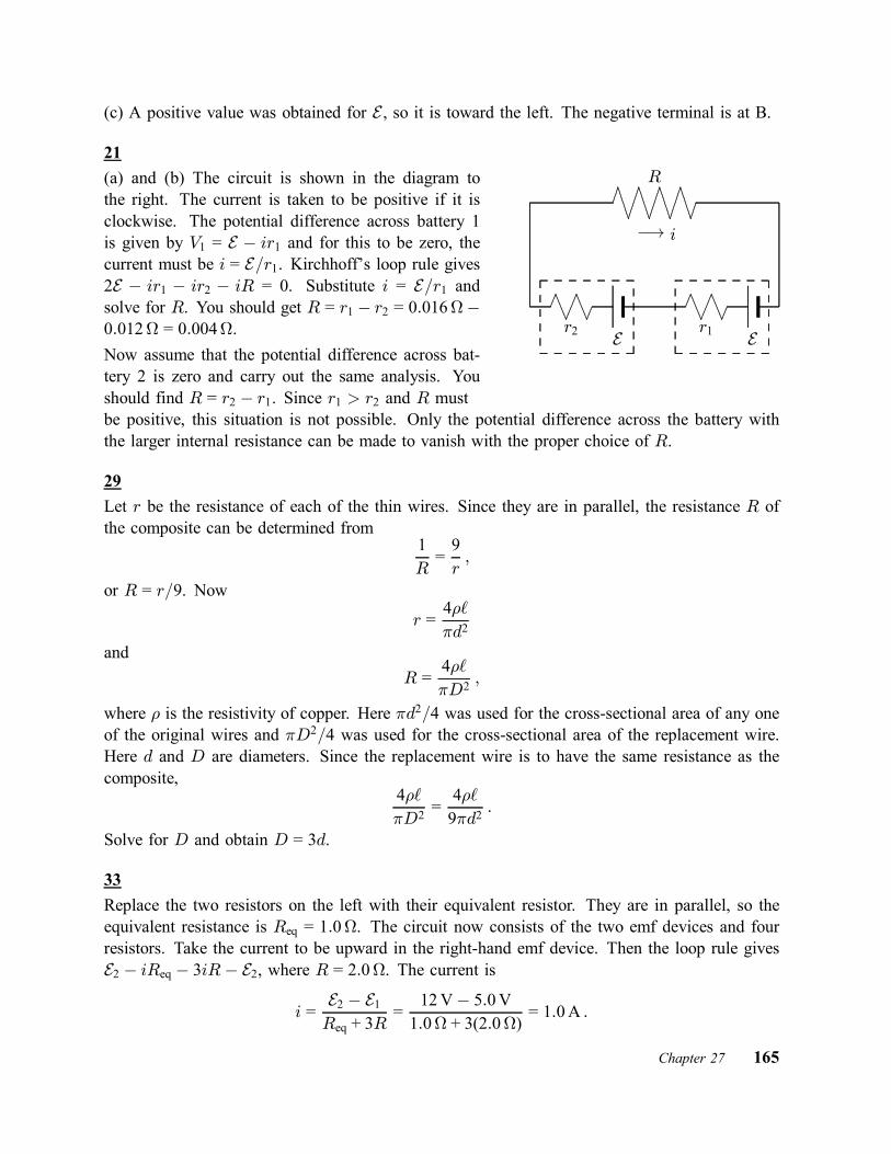
(c) A positive value was obtained for E , so it is toward the left. The negative terminal is at B.
21(a) and (b) The circuit is shown in the diagram tothe right. The current is taken to be positive if it isclockwise. The potential difference across battery 1is given by V1 = E ¡ ir1 and for this to be zero, thecurrent must be i = E=r1. Kirchhoff’s loop rule gives2E ¡ ir1 ¡ ir2 ¡ iR = 0. Substitute i = E=r1 andsolve for R. You should get R = r1 ¡ r2 = 0:016¡0:012 = 0:004.Now assume that the potential difference across bat-tery 2 is zero and carry out the same analysis. Youshould find R = r2 ¡ r1. Since r1 > r2 and R must
E..............................................................................
..............................................................................................
.................
r2
..............................................................................
..............................................................................................
.................
r1 E
..............................................................................................
....................................................................................................................
....................................................................................................................
....................................................................................................................
......................
R
¡! i
be positive, this situation is not possible. Only the potential difference across the battery withthe larger internal resistance can be made to vanish with the proper choice of R.
29Let r be the resistance of each of the thin wires. Since they are in parallel, the resistance R ofthe composite can be determined from
1R=9r;
or R = r=9. Now
r =4½`¼d2
andR =
4½`¼D2
;
where ½ is the resistivity of copper. Here ¼d2=4 was used for the cross-sectional area of any oneof the original wires and ¼D2=4 was used for the cross-sectional area of the replacement wire.Here d and D are diameters. Since the replacement wire is to have the same resistance as thecomposite,
4½`¼D2
=4½`9¼d2
:
Solve for D and obtain D = 3d.
33Replace the two resistors on the left with their equivalent resistor. They are in parallel, so theequivalent resistance is Req = 1:0. The circuit now consists of the two emf devices and fourresistors. Take the current to be upward in the right-hand emf device. Then the loop rule givesE2 ¡ iReq ¡ 3iR¡ E2, where R = 2:0. The current is
i =E2 ¡ E1Req + 3R
=12V¡ 5:0V1:0 + 3(2:0)
= 1:0A :
Chapter 27 165

To find the potential at point 1 take a path from ground, through the equivalent resistor and E2,to the point. The result is V1 = iReq¡E1 = (1:0A)(1:0)¡ 12V = ¡11V. To find the potentialat point 2 continue the path through the lowest resistor on the digram. It is V2 = V1 + iR =¡11V + (1:0A)(2:0) = ¡9:0V.
47(a) and (b) The copper wire and the aluminum jacket are connected in parallel, so the potentialdifference is the same for them. Since the potential difference is the product of the current andthe resistance, iCRC = iARA, where iC is the current in the copper, iA is the current in thealuminum, RC is the resistance of the copper, and RA is the resistance of the aluminum. Theresistance of either component is given by R = ½L=A, where ½ is the resistivity, L is the length,and A is the cross-sectional area. The resistance of the copper wire is
RC =½CL
¼a2
and the resistance of the aluminum jacket is
RA =½AL
¼(b2 ¡ a2) :
Substitute these expressions into iCRC = iARA and cancel the common factors L and ¼ to obtain
iC½Ca2
=iA½Ab2 ¡ a2 :
Solve this equation simultaneously with i = iC + iA, where i is the total current. You should get
iC =a2½Ci
(b2 ¡ a2)½C + a2½Aand
iA =(b2 ¡ a2)½Ci
(b2 ¡ a2)½C + a2½A :
The denominators are the same and each has the value
(b2 ¡ a2)½C + a2½A =£(0:380£ 10¡3 m)2 ¡ (0:250£ 10¡3 m)2¤ (1:69£ 10¡8 ¢m)
+ (0:250£ 10¡3 m)2(2:75£ 10¡8 ¢m)= 3:10£ 10¡15 ¢m3 :
ThusiC =
(0:250£ 10¡3 m)2(2:75£ 10¡8 ¢m)(2:00A)3:10£ 10¡15 ¢m3 = 1:11A
and
iA =£(0:380£ 10¡3 m)2 ¡ (0:250£ 10¡3 m)2¤ (1:69£ 10¡8 ¢m)(2:00A)
3:10£ 10¡15 ¢m3= 0:893A :
166 Chapter 27

(c) Consider the copper wire. If V is the potential difference, then the current is given byV = iCRC = iC½CL=¼a2, so
L =¼a2V
iC½C=¼(0:250£ 10¡3 m)2(12:0V)(1:11A)(1:69£ 10¡8 ¢m) = 126m :
57During charging the charge on the positive plate of the capacitor is given by Eq. 27–33, withRC = ¿ . That is,
q = CEh1¡ e¡t=¿
i;
where C is the capacitance, E is applied emf, and ¿ is the time constant. You want the time forwhich q = 0:990CE , so
0:990 = 1¡ e¡t=¿ :Thus
e¡t=¿ = 0:010 :
Take the natural logarithm of both sides to obtain t=¿ = ¡ ln 0:010 = 4:61 and t = 4:61¿ .
65(a), (b), and (c) At t = 0, the capacitor is completely uncharged and the current in the capacitorbranch is as it would be if the capacitor were replaced by a wire. Let i1 be the current in R1 andtake it to be positive if it is to the right. Let i2 be the current in R2 and take it to be positiveif it is downward. Let i3 be the current in R3 and take it to be positive if it is downward. Thejunction rule produces i1 = i2 + i3, the loop rule applied to the left-hand loop produces
E ¡ i1R1 ¡ i2R2 = 0 ;
and the loop rule applied to the right-hand loop produces
i2R2 ¡ i3R3 = 0 :
Since the resistances are all the same, you can simplify the mathematics by replacing R1, R2,and R3 with R. The solution to the three simultaneous equations is
i1 =2E3R
=2(1:2£ 103 V)3(0:73£ 106) = 1:1£ 10
¡3 A
andi2 = i3 =
E3R
=1:2£ 103 V
3(0:73£ 106) = 5:5£ 10¡4 A :
(d), (e), and (f) At t =1, the capacitor is fully charged and the current in the capacitor branchis zero. Then i1 = i2 and the loop rule yields
E ¡ i1R1 ¡ i1R2 = 0 :Chapter 27 167

The solution isi1 = i2 =
E2R
=1:2£ 103 V
2(0:73£ 106) = 8:2£ 10¡4 A :
(g) and (h) The potential difference across resistor 2 is V2 = i2R2. At t = 0 it is
V2 = (5:5£ 10¡4 A)(0:73£ 106) = 4:0£ 102 Vand at t =1 it is
V2 = (8:2£ 10¡4 A)(0:73£ 106 ) = 6:0£ 102 V :(i) The graph of V2 versus t is shown to the right.
t
V2
E=6
E=3
E=2
......................................................................................................................
...................................................
......................................................................................
.........................................................................................................................................
73As the capacitor discharges the potential difference across its plates at time t is given by V =V0e
¡t=¿ , where V0 is the potential difference at time t = 0 and ¿ is the capacitive time constant.This equation is solved for the time constant, with result
¿ = ¡ t
ln(V=V0):
Since the time constant is ¿ = RC, where RR is the resistance and C is the capacitance,
R = ¡ t
C ln(V=V0):
For the smaller time interval
R = ¡ 10:0£ 10¡6 s(0:220£ 10¡6 F) ln
µ0:800V5:00V
¶ = 24:8 :and for the larger time interval
R = ¡ 6:00£ 10¡3 s(0:220£ 10¡6 F) ln
µ0:800V5:00V
¶ = 1:49£ 104 :75(a) Let i be the current, which is the same in both wires, and E be the applied potential difference.Then the loop equation gives E ¡ iRA ¡ iRB = 0 and the current is
i =E
RA +RB=
60:0V0:127 + 0:729
= 70:1A :
168 Chapter 27

The current density in wire A is
JA =i
¼r2A=
70:1A¼(1:30£ 10¡3 m)2 = 1:32£ 10
7 A=m2 :
(b) The potential difference across wire A is VA = iRA = (70:1A)(0:127) = 8:90V.(c) The resistance is RA = ½AL=A, where ½ is the resistivity, A is the cross-sectional area, andL is the length. The resistivity of wire A is
½A =RAA
L=(0:127)¼(1:30£ 10¡3 m)2
40:0m= 1:69£ 10¡8 ¢m :
According to Table 26–1 the material is copper.(d) Since wire B has the same diameter and length as wire A and carries the same current, thecurrent density in it is the same, 1:32£ 107 A=m2.(e) The potential difference across wire B is VB = iRB = (70:1A)(0:729) = 51:1V.(f) The resistivity of wire B is
½B =RBA
L=(0:729)¼(1:30£ 10¡3 m)2
40:0m= 9:68£ 10¡8 ¢m :
According to Table 26–1 the material is iron.
77The three circuit elements are in series, so the current is the same in all of them. Since the batteryis discharging, the potential difference across its terminals is Vbatt = E ¡ ir, where E is its emfand r is its internal resistance. Thus
r =E ¡ Vi
=12V¡ 11:4V
50A= 0:012 :
This is less than 0:0200, so the battery is not defective.The resistance of the cable is Rcable = Vcable=i = (3:0V)=(50A = 0:060, which is greater than0:040. The cable is defective.The potential difference across the motor is Vmotor = 11:4V ¡ 3:0V = 8:4V and its resistanceis Rmotor = Vmotor=i = (8:4V)=(50A) = 0:17, which is less than 0:200. The motor is notdefective.
85Let RS0 be the resistance of the silicon resistor at 20± and RI0 be the resistance of the iron resistorat that temperature. At some other temperature T the resistance of the silicon resistor is RS =RS0 +®SRS0(T ¡ 20±C) and the resistance of the iron resistor is RI = RI0 +®IRI0(T ¡ 20±C).Here ®S and ®I are the temperature coefficients of resistivity. The resistors are series so theresistance of the combination is
R = RS0 +RI0 + (®SRS0 + ®IRI0)(T ¡ 20±C) :We want RS0 + RI0 to be 1000 and ®SRS0 + ®IRI0 to be zero. Then the resistance of thecombination will be independent of the temperature.
Chapter 27 169

The second equation gives RI0 = ¡(®S=®I )RS0 and when this is used to substitute for RI0 inthe first equation the result is RS0 ¡ (®S=®I)RS0 = 1000. The solution for RS0 is
RS0 =1000®S®I¡ 1
=1000
¡70£ 10¡3 K¡16:5£ 10¡3 K¡1 ¡ 1
= 85 ;
where values for the temperature coefficients of resistivity were obtained from Table 26–1. Theresistance of the iron resistor is RI0 = 1000¡ 85 = 915.
95When the capacitor is fully charged the potential difference across its plates is E and the energystored in it is U = 1
2CE2.(a) The current is given as a function of time by i = (E=R)e¡t=¿ , where ¿ (= RC) is the capacitivetime constant. The rate with which the emf device supplies energy is PE = iE and the energysupplied in fully charging the capacitor is
EE =Z 1
0PE dt =
E2R
Z 1
0e¡t=¿ dt =
E2¿R=E2RCR
= CE2 :
This is twice the energy stored in the capacitor.(b) The rate with which energy is dissipated in the resistor is PR = i2R and the energy dissipatedas the capacitor is fully charged is
ER =Z 1
0PR dt =
E2R
Z 1
0e¡2t=¿ dt =
E2¿2R
=E2RC2R
= 12CE2 :
97(a) Immediately after the switch is closed the capacitor is uncharged and since the charge onthe capacitor is given by q = CVC , the potential difference across its plates is zero. Applythe loop rule to the right-hand loop to find that the potential difference across R2 must also bezero. Now apply the loop rule to the left-hand loop to find that E ¡ i1R1 = 0 and i1 = E=R1 =(30V)=(20£ 103) = 1:5£ 10¡3 A.(b) Since the potential difference across R2 is zero and this potential difference is given byVR2 = i2R2, i2 = 0.(c) A long time later, when the capacitor is fully charged, the current is zero in the capacitorbranch and the current is the same in the two resistors. The loop rule applied to the left-hand loopgives E ¡ iR1¡ iR2 = 0, so i = E=(R1 +R2) = (30V)=(20£ 103+ 10£ 103) = 1:0£ 10¡3 A.
99(a) R2 and R3 are in parallel, with an equivalent resistance of R2R3=(R2 +R3), and this combi-nation is in series with R1, so the circuit can be reduced to a single loop with an emf E and aresistance Req = R1 +R2R3=(R2 + R3) = (R1R2 +R1R3 +R2R3)=(R1 +R2). The current is
i =EReq
=(R2 + R3)E
R1R2 +R1R3 +R2R3:
170 Chapter 27

The rate with which the battery supplies energy is
P = iE = (R2 +R3)E2R1R2 +R1R3 +R2R3
:
The derivative with respect to R3 is
dP
dR3=
E2R1R2 +R1R3 +R2R3
¡ (R2 + R3)(R1 +R2)E2(R1R2 +R1R3 +R2R3)2
= ¡ E2R22(R1R2 +R1R3 +R2R3)2
;
where the last form was obtained with a little algebra. The derivative is negative for all (positive)values of the resistances, so P has its maximum value for R3 = 0.(b) Substitute R3 = 0 in the expression for P to obtain
P =R1E2R1R2
=E2R1=12:0V10:0
= 14:4W :
101If the batteries are connected in series the total emf in the circuit is NE and the equivalentresistance is R + nr, so the current is i = NE=(R +Nr). If R = r, then i = NE=(N + 1)r.If the batteries are connected in parallel then the emf in the circuit is E and the equivalentresistance is R + r=N , so the current is i = E=(R + r=N ) = NE=(NR + r). If R = r, i =NE=(N + 1)r, the same as when they are connected in series.
Chapter 27 171

Chapter 28
3(a) The magnitude of the magnetic force on the proton is given by FB = evB sinÁ, where v isthe speed of the proton, B is the magnitude of the magnetic field, and Á is the angle betweenthe particle velocity and the field when they are drawn with their tails at the same point. Thus
v =FB
eB sinÁ=
6:50£ 10¡17 N(1:60£ 10¡19 C)(2:60£ 10¡3 T) sin 23:0± = 4:00£ 10
5 m=s :
(b) The kinetic energy of the proton is
K = 12mv
2 = 12(1:67£ 10¡27 kg)(4:00£ 105 m=s)2 = 1:34£ 10¡16 J :
This is (1:34£ 10¡16 J)=(1:60£ 10¡19 J=eV) = 835 eV.
17(a) Since the kinetic energy is given by K = 1
2mv2, where m is the mass of the electron and v
is its speed,
v =r2Km=
s2(1:20£ 103 eV)(1:60£ 10¡19 J=eV)
9:11£ 10¡31 kg = 2:05£ 107 m=s :
(b) The magnitude of the magnetic force is given by evB and the acceleration of the electron isgiven by v2=r, where r is the radius of the orbit. Newton’s second law is evB = mv2=r, so
B =mv
er=(9:11£ 10¡31 kg)(2:05£ 107 m=s)(1:60£ 10¡19 C)(25:0£ 10¡2 m) = 4:68£ 10
¡4 T = 468¹T :
(c) The frequency f is the number of times the electron goes around per unit time, so
f =v
2¼r=
2:05£ 107 m=s2¼(25:0£ 10¡2 m) = 1:31£ 10
7 Hz = 13:1MHz :
(d) The period is the reciprocal of the frequency:
T =1f=
11:31£ 107 Hz = 7:63£ 10
¡8 s = 76:3 ns :
29(a) If v is the speed of the positron, then v sinÁ is the component of its velocity in the planethat is perpendicular to the magnetic field. Here Á is the angle between the velocity and the field(89±). Newton’s second law yields eBv sinÁ = m(v sinÁ)2=r, where r is the radius of the orbit.Thus r = (mv=eB) sinÁ. The period is given by
T =2¼rv sinÁ
=2¼meB
=2¼(9:11£ 10¡31 kg)
(1:60£ 10¡19 C)(0:100 T) = 3:58£ 10¡10 s :
The expression for r was substituted to obtain the second expression for T .
172 Chapter 28

(b) The pitch p is the distance traveled along the line of the magnetic field in a time interval ofone period. Thus p = vT cosÁ. Use the kinetic energy to find the speed: K = 1
2mv2 yields
v =r2Km=
s2(2:0£ 103 eV)(1:60£ 10¡19 J=eV)
9:11£ 10¡31 kg = 2:651£ 107 m=s :
Thusp = (2:651£ 107 m=s)(3:58£ 10¡10 s) cos 89:0± = 1:66£ 10¡4 m :
(c) The orbit radius is
r =mv sinÁeB
=(9:11£ 10¡31 kg)(2:651£ 107 m=s) sin 89:0±
(1:60£ 10¡19 C)(0:100 T) = 1:51£ 10¡3 m :
41(a) The magnitude of the magnetic force on the wire is given by FB = iLB sinÁ, where i is thecurrent in the wire, L is the length of the wire, B is the magnitude of the magnetic field, and Áis the angle between the current and the field. In this case Á = 70±. Thus
FB = (5000A)(100m)(60:0£ 10¡6 T) sin 70± = 28:2N :(b) Apply the right-hand rule to the vector product ~FB = i~L£ ~B to show that the force is to thewest.
47
.......
......
.......
......
............. ............. ............. ............. ............. ............. ............. ............. ..................................
..........................
...
.......
.......
.......
.......
.......
.......
.......
.......
.......
.......
.........................
......................
.............................................................................
...................... i
..................................................................................................................
... ~B..........................................................................
......................
~F
µ
y
x
z
....................
....................
....................
....................
....................
....................
....................
....................
....................
....................
.......................................................................................................................................................................................................................................................................................................................................................................................................................................................................................................................
.........................................
a
b...............................................................................................
......................
.........................................................................................................................................................................................................................a
z
x
~F
µ
The situation is shown in the left diagram above. The y axis is along the hinge and the magneticfield is in the positive x direction. A torque around the hinge is associated with the wire oppositethe hinge and not with the other wires. The force on this wire is in the positive z direction andhas magnitude F = NibB, where N is the number of turns.The right diagram shows the view from above. The magnitude of the torque is given by
¿ = Fa cos µ = NibBa cos µ= 20(0:10A)(0:10m)(0:50£ 10¡3 T)(0:050m) cos 30±= 4:3£ 10¡3 N ¢m :
Chapter 28 173

Use the right-hand rule to show that the torque is directed downward, in the negative y direction.Thus ~¿ = ¡(4:3£ 10¡3 N ¢m) j.
55(a) The magnitude of the magnetic dipole moment is given by ¹ = NiA, where N is the numberof turns, i is the current in each turn, and A is the area of a loop. In this case the loops arecircular, so A = ¼r2, where r is the radius of a turn. Thus
i =¹
N¼r2=
2:30A ¢m2(160)(¼)(0:0190m)2
= 12:7A :
(b) The maximum torque occurs when the dipole moment is perpendicular to the field (or theplane of the loop is parallel to the field). It is given by ¿ = ¹B = (2:30A ¢m2)(35:0£ 10¡3 T) =8:05£ 10¡2 N ¢m.
59The magnitude of a magnetic dipole moment of a current loop is given by ¹ = iA, where i isthe current in the loop and A is the area of the loop. Each of these loops is a circle and its areais given by A = ¼R2, where R is the radius. Thus the dipole moment of the inner loop has amagnitude of ¹i = i¼r21 = (7:00A)¼(0:200m)2 = 0:880A ¢m2 and the dipole moment of the outerloop has a magnitude of ¹o = i¼r22 = (7:00A¼(0:300m)2 = 1:979A ¢m2.(a) Both currents are clockwise in Fig. 28–51 so, according to the right-hand rule, both dipolemoments are directed into the page. The magnitude of the net dipole moment is the sum of themagnitudes of the individual moments: ¹net = ¹i +¹o = 0:880A ¢m2 +1:979A ¢m2 = 2:86A ¢m2.The net dipole moment is directed into the page.(b) Now the dipole moment of the inner loop is directed out of the page. The moments are inopposite directions, so the magnitude of the net moment is ¹net = ¹o ¡ ¹i = 1:979A ¢ m2 ¡0:880A ¢m2 = 1:10A ¢m2. The net dipole moment is again into the page.
63If N closed loops are formed from the wire of length L, the circumference of each loop is L=N ,the radius of each loop is R = L=2¼N , and the area of each loop is A = ¼R2 = ¼(L=2¼N )2 =L2=4¼N 2. For maximum torque, orient the plane of the loops parallel to the magnetic field, sothe dipole moment is perpendicular to the field. The magnitude of the torque is then
¿ = NiAB = (Ni)µ
L2
4¼N 2
¶B =
iL2B
4¼N:
To maximize the torque, take N to have the smallest possible value, 1. Then
¿ =iL2B
4¼=(4:51£ 10¡3 A)(0:250m)2(5:71£ 10¡3 T)
4¼= 1:28£ 10¡7 N ¢m :
65(a) the magnetic potential energy is given by U = ¡~¹ ¢ ~B, where ~¹ is the magnetic dipole momentof the coil and ~B is the magnetic field. The magnitude of the magnetic moment is ¹ = NiA,
174 Chapter 28
where i is the current in the coil, A is the area of the coil, and N is the number of turns. Themoment is in the negative y direction, as you can tell by wrapping the fingers of your right handaround the coil in the direction of the current. Your thumb is then in the negative y direction.Thus ~¹ = ¡(3:00)(2:00A)(4:00£ 10¡3 m2) j = ¡(2:40£ 10¡2 A ¢m2) j. The magnetic potentialenergy is
U = ¡(¹y j) ¢ (Bx i +By j +Bz k) = ¡¹yBy= ¡(¡2:40£ 10¡2 A ¢m2)(¡3:00£ 10¡3 T) = ¡7:20£ 10¡5 J ;
where j ¢ i = 0, j ¢ j = 1, and j ¢ k = 0 were used.(b) The magnetic torque on the coil is
~¿ = ~¹£ ~B = (¹y j)£ (Bx i +By j +Bz k) = ¹yBz i¡ ¹yBx k= (¡2:40£ 10¡2 A ¢m2)(¡4:00£ 10¡3 T) i¡ (¡2:40£ 10¡2 A ¢m2)(2:00£ 10¡3 T) k= (9:6£ 10¡5 N ¢m) i + (4:80£ 10¡5 N ¢m)k ;
where j £ i = ¡k, j £ j = 0, and j£ k = i were used.
73
The net force on the electron is given by ~F = ¡e( ~E + ~v £ ~B), where ~E is the electric field, ~Bis the magnetic field, and ~v is the electron’s velocity. Since the electron moves with constantvelocity you know that the net force must vanish. Thus
~E = ¡~v £ ~B = ¡(v i)£ (B k) = ¡vB j = ¡(100m=s)(5:00T) j = (500V=m) j :
75(a) and (b) Suppose the particles are accelerated from rest through an electric potential differenceV . Since energy is conserved the kinetic energy of a particle is K = qV , where q is theparticle’s charge. The ratio of the proton’s kinetic energy to the alpha particle’s kinetic energy isKp=K® = e=2e = 0:50. The ratio of the deuteron’s kinetic energy to the alpha particle’s kineticenergy is Kd=K® = e=2e = 0:50.(c) The magnitude of the magnetic force on a particle is qvB and, according to Newton’s secondlaw, this must equal mv2=R, where v is its speed and R is the radius of its orbit. Sincev =
p2K=m =
p2qV=m,
R =mv
qB=m
qB
r2Km=m
qB
r2qVm
=
s2mqB2
:
The ratio of the radius of the deuteron’s path to the radius of the proton’s path is
RdRp
=r2:0 u1:0 u
re
e= 1:4 :
Since the radius of the proton’s path is 10 cm, the radius of the deuteron’s path is (1:4)(10 cm) =14 cm.
Chapter 28 175

(d) The ratio of the radius of the alpha particle’s path to the radius of the proton’s path is
R®Rp
=r4:0 u1:0 u
re
2e= 1:4 :
Since the radius of the proton’s path is 10 cm, the radius of the deuteron’s path is (1:4)(10 cm) =14 cm.
77Take the velocity of the particle to be ~v = vx i + vy j and the magnetic field to be B i. Themagnetic force on the particle is then
~F = q~v £ ~B = q(vx i + vy j)£ (B i) = ¡qvyB k ;where q is the charge of the particle. We used i£ i = 0 and j £ i = ¡k. The charge is
q =F
¡vyB =0:48N
¡(4:0£ 103 m=s)(sin 37±)(5:0£ 10¡3 T) = ¡4:0£ 10¡2 C :
81(a) If K is the kinetic energy of the electron and m is its mass, then its speed is
v =r2Km=
s2(12£ 103 eV)(1:60£ 10¡19 J=eV)
9:11£ 10¡31 = 6:49£ 107 m=s :
Since the electron is traveling along a line that is parallel to the horizontal component of Earth’smagnetic field, that component does not enter into the calculation of the magnetic force on theelectron. The magnitude of the force on the electron is evB and since F = ma, where a is themagnitude of its acceleration, evB = ma and
a =evB
m=(1:60£ 10¡19 C)(6:49£ 107 m=s)(55:0£ 10¡6 T)
9:11£ 10¡31 kg = 6:3£ 1014 m=s2 :
(b) If the electron does not get far from the x axis we may neglect the influence of the horizontalcomponent of Earth’s field and assume the electron follows a circular path. Its acceleration isgiven by a = v2=R, where R is the radius of the path. Thus
R =v2
a=(6:49£ 107 m=s)26:27£ 1014 m=s2 = 6:72m :
The solid curve on the diagram is the path. Suppose it subtendsthe angle µ at its center. d (= 0:200m) is the distance traveledalong the x axis and ` is the deflection. The right triangleyields d = R sin µ, so sin µ = d=R and cos µ =
p1¡ sin2 µ =p
1¡ (x=R)2. The triangle also gives ` = R ¡ R cos µ, so` = R¡Rp1¡ (x=R)2. Substitute R = 6:72m and d = 0:2mto obtain ` = 0:0030m.
x
y................................................................................................................................................................................................................................................................................
.............................................................................................................................................................................................................................................
R
`
d
µ
176 Chapter 28

Chapter 29
7(a) If the currents are parallel, the two magnetic fields are in opposite directions in the regionbetween the wires. Since the currents are the same, the net field is zero along the line that runshalfway between the wires. There is no possible current for which the field does not vanish. Ifthere is to be a field on the bisecting line the currents must be in opposite directions. Then thefields are in the same direction in the region between the wires.(b) At a point halfway between the wires, the fields have the same magnitude, ¹0i=2¼r. Thusthe net field at the midpoint has magnitude B = ¹0i=¼r and
i =¼rB
¹0=¼(0:040m)(300£ 10¡6 T)4¼ £ 10¡7 T ¢m=A = 30A :
15Sum the fields of the two straight wires and the circular arc. Look at the derivation of theexpression for the field of a long straight wire, leading to Eq. 29–6. Since the wires we areconsidering are infinite in only one direction, the field of either of them is half the field of aninfinite wire. That is, the magnitude is ¹0i=4¼R, where R is the distance from the end of thewire to the center of the arc. It is the radius of the arc. The fields of both wires are out of thepage at the center of the arc.Now find an expression for the field of the arc at its center. Divide the arc into infinitesimalsegments. Each segment produces a field in the same direction. If ds is the length of a segment,the magnitude of the field it produces at the arc center is (¹0i=4¼R2) ds. If µ is the anglesubtended by the arc in radians, then Rµ is the length of the arc and the net field of the arc is¹0iµ=4¼R. For the arc of the diagram, the field is into the page. The net field at the center, dueto the wires and arc together, is
B =¹0i
4¼R+¹0i
4¼R¡ ¹0iµ4¼R
=¹0i
4¼R(2¡ µ) :
For this to vanish, µ must be exactly 2 radians.
19Each wire produces a field with magnitude given by B = ¹0i=2¼r, where r is the distance fromthe corner of the square to the center. According to the Pythagorean theorem, the diagonal ofthe square has length
p2a, so r = a=
p2 and B = ¹0i=
p2¼a. The fields due to the wires at the
upper left and lower right corners both point toward the upper right corner of the square. The
Chapter 29 177
fields due to the wires at the upper right and lower left corners both point toward the upper leftcorner. The horizontal components cancel and the vertical components sum to
Bnet = 4¹0ip2¼a
cos 45± =2¹0i¼a
=2(4¼ £ 10¡7 T ¢m=A)(20A)
¼(0:20m)= 8:0£ 10¡5 T :
In the calculation cos 45± was replaced with 1=p2. In unit vector notation ~B = (8:0£ 10¡5 T) j.
21Follow the same steps as in the solution of Problem 17 above but change the lower limit ofintegration to ¡L, and the upper limit to 0. The magnitude of the net field is
B =¹0iR
4¼
Z 0
¡L
dx
(x2 +R2)3=2=¹0iR
4¼1R2
x
(x2 +R2)1=2
¯0¡L=¹0i
4¼RLp
L2 +R2
=4¼ £ 10¡7 T ¢m=A)(0:693A)
4¼(0:251m)0:136mp
(0:136m)2 + (0:251m)2= 1:32£ 10¡7 T :
31The current per unit width of the strip is i=w and the current through a width dx is (i=w) dx.Treat this as a long straight wire. The magnitude of the field it produces at a point that is adistance d from the edge of the strip is dB = (¹0=2¼)(i=w) dx=x and the net field is
B =¹0i
2¼w
Z d+w
d
dx
x=¹02¼w
lnd + wd
=(4¼ £ 10¡7 T ¢m=A)(4:61£ 10¡6 A)
2¼(0:0491m)ln0:0216m + 0:0491m
0:0216m= 2:23£ 10¡11 T :
35The magnitude of the force of wire 1 on wire 2 is given by¹0i1i2=2¼r, where i1 is the current in wire 1, i2 is the currentin wire 2, and r is the separation of the wires. The distancebetween the wires is r =
qd21 + d22. Since the currents are
in opposite directions the wires repel each other so the forceon wire 2 is along the line that joins the wires and is awayfrom wire 1.
¯
"jd1j#á¡¡ d2 ¡¡¡!
.....................................................................................................................................................................................................................................................................
qd21 + d22
......................................................................................................................................................... ...................... ~F
xµ
To find the x component of the force, multiply the magnitude of the force by the cosine of theangle µ that the force makes with the x axis. This is cos µ = d2=
qd21 + d22. Thus the x component
178 Chapter 29

of the force is
Fx =¹0i1i22¼
d2d21 + d22
=(2¼ £ 10¡7 T ¢m=A)(4:00£ 10¡3 A)(6:80£ 10¡3 A)
2¼0:0500m
(0:024m)2 + (5:00m)2
= 8:84£ 10¡11 T :
43(a) Two of the currents are out of the page and one is into the page, so the net current enclosedby the path is 2:0A, out of the page. Since the path is traversed in the clockwise sense, a currentinto the page is positive and a current out of the page is negative, as indicated by the right-handrule associated with Ampere’s law. Thus ienc = ¡i andI
~B ¢ d~s = ¡¹0i = ¡(4¼ £ 10¡7 T ¢m=A)(2:0A) = ¡2:5£ 10¡6 T ¢m :
(b) The net current enclosed by the path is zero (two currents are out of the page and two areinto the page), so
H~B ¢ d~s = ¹0ienc = 0.
53(a) Assume that the point is inside the solenoid. The field of the solenoid at the point is parallelto the solenoid axis and the field of the wire is perpendicular to the solenoid axis. The net fieldmakes an angle of 45± with the axis if these two fields have equal magnitudes.The magnitude of the magnetic field produced by a solenoid at a point inside is given by Bsol =¹0isoln, where n is the number of turns per unit length and isol is the current in the solenoid.The magnitude of the magnetic field produced by a long straight wire at a point a distance raway is given by Bwire = ¹0iwire=2¼r, where iwire is the current in the wire. We want ¹0nisol =¹0iwire=2¼r. The solution for r is
r =iwire2¼nisol
=6:00A
2¼(10:0£ 102 m¡1)(20:0£ 10¡3 A) = 4:77£ 10¡2 m = 4:77 cm :
This distance is less than the radius of the solenoid, so the point is indeed inside as we assumed.(b) The magnitude of the either field at the point is
Bsol = Bwire = ¹0nisol = (4¼ £ 10¡7 T ¢m=A)(10:0£ 102 m¡1)(20:0£ 10¡3 A) = 2:51£ 10¡5 T :Each of the two fields is a vector component of the net field, so the magnitude of the net fieldis the square root of the sum of the squares of the individual fields: B =
p2(2:51£ 10¡5 T)2 =
3:55£ 10¡5 T.
57The magnitude of the dipole moment is given by ¹ = NiA, where N is the number of turns, iis the current, and A is the area. Use A = ¼R2, where R is the radius. Thus
¹ = Ni¼R2 = (200)(0:30A)¼(0:050m)2 = 0:47A ¢m2 :Chapter 29 179

65(a) Take the magnetic field at a point within the hole to be the sum of the fields due to twocurrent distributions. The first is the solid cylinder obtained by filling the hole and has a currentdensity that is the same as that in the original cylinder with the hole. The second is the solidcylinder that fills the hole. It has a current density with the same magnitude as that of the originalcylinder but it is in the opposite direction. Notice that if these two situations are superposed, thetotal current in the region of the hole is zero.Recall that a solid cylinder carrying current i, uniformly distributed over a cross section, producesa magnetic field with magnitude B = ¹0ir=2¼R2 a distance r from its axis, inside the cylinder.Here R is the radius of the cylinder.For the cylinder of this problem, the current density is
J =i
A=
i
¼(a2 ¡ b2) ;
where A (= ¼(a2 ¡ b2)) is the cross-sectional area of the cylinder with the hole. The current inthe cylinder without the hole is
i1 = JA1 = ¼Ja2 =ia2
a2 ¡ b2and the magnetic field it produces at a point inside, a distance r1 from its axis, has magnitude
B1 =¹0i1r12¼a2
=¹0ir1a
2
2¼a2(a2 ¡ b2) =¹0ir1
2¼(a2 ¡ b2) :
The current in the cylinder that fills the hole is
i2 = ¼Jb2 =ib2
a2 ¡ b2and the field it produces at a point inside, a distance r2 from the its axis, has magnitude
B2 =¹0i2r22¼b2
=¹0ir2b
2
2¼b2(a2 ¡ b2) =¹0ir2
2¼(a2 ¡ b2) :
At the center of the hole, this field is zero and the field there is exactly the same as it would beif the hole were filled. Place r1 = d in the expression for B1 and obtain
B =¹0id
2¼(a2 ¡ b2) =(4¼ £ 10¡7 T ¢m=A)(5:25A)(0:0200m)
2¼[(0:0400m)2 ¡ (0:0150m)2] = 1:53£ 10¡5 T
for the field at the center of the hole. The field points upward in the diagram if the current isout of the page.(b) If b = 0, the formula for the field becomes
B =¹0id
2¼a2:
This correctly gives the field of a solid cylinder carrying a uniform current i, at a point insidethe cylinder a distance d from the axis. If d = 0, the formula gives B = 0. This is correct for thefield on the axis of a cylindrical shell carrying a uniform current.
180 Chapter 29
(c) The diagram shows the situation in a cross-sectionalplane of the cylinder. P is a point within the hole, A ison the axis of the cylinder, and C is on the axis of thehole. The magnetic field due to the cylinder without thehole, carrying a uniform current out of the page, is labeled~B1 and the magnetic field of the cylinder that fills the hole,carrying a uniform current into the page, is labeled ~B2. Theline from A to P makes the angle µ1 with the line that joinsthe centers of the cylinders and the line from C to P makesthe angle µ2 with that line, as shown. ~B1 is perpendicularto the line from A to P and so makes the angle µ1 with thevertical. Similarly, ~B2 is perpendicular to the line from Cto P and so makes the angle µ2 with the vertical.
.......................................................................................................................................................................................................................................................................................................................
........................................................................................................................................................................................................
...................................................................................................................................................................................................................
x
y
P
~B1~B2
A Cd
µ1 µ2
µ1 µ2
r1 r2
The x component of the total field is
Bx = B2 sin µ2 ¡B1 sin µ1 = ¹0ir22¼(a2 ¡ b2) sin µ2 ¡
¹0ir12¼(a2 ¡ b2) sin µ1
=¹0i
2¼(a2 ¡ b2) [r2 sin µ2 ¡ r1 sin µ1] :
As the diagram shows, r2 sin µ2 = r1 sin µ1, so Bx = 0. The y component is given by
By = B2 cos µ2 +B1 cos µ1 =¹0ir2
2¼(a2 ¡ b2) cos µ2 +¹0ir1
2¼(a2 ¡ b2) cos µ1
=¹0i
2¼(a2 ¡ b2) [r2 cos µ2 + r1 cos µ1] :
The diagram shows that r2 cos µ2 + r1 cos µ1 = d, so
By =¹0id
2¼(a2 ¡ b2) :
This is identical to the result found in part (a) for the field on the axis of the hole. It is independentof r1, r2, µ1, and µ2, showing that the field is uniform in the hole.
71Use the Biot-Savart law in the form
~B =¹04¼i¢~s£ ~rr3
:
Take ¢~s to be ¢s j, and ~r to be x i+y j +z k. Then ¢~s£~r = ¢s j£(x i+y j +z k) = ¢s(z i¡x k),where j £ i = ¡k, j £ j = 0, and j £ k = i were used. In addition, r =
px2 + y2 + z2. The
Biot-Savart equation becomes~B =
¹04¼
i¢s(z i¡ z k)(x2 + y2 + z2)3=2
:
Chapter 29 181

(a) For x = 0, y = 0, and z = 5:0m,
~B =4¼ £ 10¡7 T ¢m=A
4¼(2:0A)(0:030m)(5:0m) i
(5:0m)3= (2:4£ 10¡10 T) i :
(b) For x = 0, y = 6:0m, and z = 0, ~B = 0.(c) For x = 7:0m, y = 7:0m, and z = 0,
~B =4¼ £ 10¡7 T ¢m=A
4¼(2:0A)(0:030m)(¡7:0m) k[(7:0m)2 + (7:0m)2]3=2
= (4:3£ 10¡11 T) k :
(d) For x = ¡3:0m, y = ¡4:0m, and z = 0,
~B =4¼ £ 10¡7 T ¢m=A
4¼(2:0A)(0:030m)(3:0m) k[(¡3:0m)2 + (¡4:0m)2]3=2 = (1:4£ 10
¡10 T) k :
77First consider the finite wire segment shown on the right.It extends from y = ¡d to y = a¡d, where a is the lengthof the segment, and it carries current i in the positive ydirection. Let dy be an infinitesimal length of wire atcoordinate y. According to the Biot-Savart law the mag-nitude of the magnetic field at P due to this infinitesimallength is dB = (¹0=4¼)(i sin µ=r2) dy. Now r2 = y2 +R2and sin µ = R=r = R=
py2 +R2, so
dB =¹04¼
iR
(y2 +R2)3=2dy
and the field of the entire segment is
P.........................
.................................................
.................................................
.................................................
.................................................
.......................
r
y
x...............................................................................................
......................
i
...................
R
dyµ
B =¹04¼iR
Z a¡d
¡d
y
(y2 +R2)3=2dy = ¹0=4¼
i
R
"a¡ dp
R2 + (a¡ d)2 +dp
R2 + d2
#;
where integral 19 of Appendix E was used.All four sides of the square produce magnetic fields that are into the page at P, so we sum theirmagnitudes. To calculate the field of the left side of the square put d = 3a=4 and R = a=4. Theresult is
Bleft =¹04¼4ia
∙1p2+3p10
¸=¹O3¼4ia(1:66) :
The field of the upper side of the square is the same. To calculate the field of the right side ofthe square put d = a=4 and R = 3a=4. The result is
Bright =¹04¼4i3a
∙3p18+1p10
¸=¹O3¼4ia(0:341) :
182 Chapter 29
The field of the bottom side is the same. The total field at P is
B = Bleft +Bupper +Bright +Blower =¹04¼4ia(1:66 + 1:66 + 0:341 + 0:341)
=4¼ £ 10¡7 T ¢m=A
4¼4(10A)0:080m
(4:00) = 2:0£ 10¡4 T :
79(a) Suppose the field is not parallel to the sheet, as shownin the upper diagram. Reverse the direction of the current.According to the Biot-Savart law, the field reverses, so it willbe as in the second diagram. Now rotate the sheet by 180±about a line that is perpendicular to the sheet. The field,of course, will rotate with it and end up in the directionshown in the third diagram. The current distribution is nowexactly as it was originally, so the field must also be as itwas originally. But it is not. Only if the field is parallelto the sheet will be final direction of the field be the sameas the original direction. If the current is out of the page,any infinitesimal portion of the sheet in the form of a longstraight wire produces a field that is to the left above thesheet and to the right below the sheet. The field must be asdrawn in Fig. 29–85.
....................................
......................................
................................................
.................................................................................................... ......................
....................................................................................................
......................
(b) Integrate the tangential component of the magnetic fieldaround the rectangular loop shown with dotted lines. Theupper and lower edges are the same distance from the currentsheet and each has length L. This means the field has thesame magnitude along these edges. It points to the left alongthe upper edge and to the right along the lower. á¡¡ L ¡¡¡!
~B á
¡! ~B
If the integration is carried out in the counterclockwise sense, the contribution of the upper edgeis BL, the contribution of the lower edge is also BL, and the contribution of each of the sidesis zero because the field is perpendicular to the sides. Thus
H~B ¢ d~s = 2BL. The total current
through the loop is ¸L. Ampere’s law yields 2BL = ¹0¸L, so B = ¹0¸=2.
81(a) Use a circular Amperian path that has radius r and is concentric with the cylindrical shellas shown by the dotted circle on Fig. 29–86. The magnetic field is tangent to the path andhas uniform magnitude on it, so the integral on the left side of the Ampere’s law equation isH~B ¢d~s = 2¼rB. The current through the Amperian path is the current through the region outside
the circle of radius b and inside the circle of radius r. Since the current is uniformly distributedthrough a cross section of the shell, the enclosed current is i(r2 ¡ b2)=(a2 ¡ b2). Thus
2¼rB =r2 ¡ b2a2 ¡ b2 i
Chapter 29 183
and
B =¹0i
2¼(a2 ¡ b2)r2 ¡ b2r
:
(b) When r = a this expression reduce to B = ¹0i=2¼r, which is the correct expression for thefield of a long straight wire. When r = b it reduces to B = 0, which is correct since there is nofield inside the shell. When b = 0 it reduces to B = ¹0ir=2¼a2, which is correct for the fieldinside a cylindrical conductor.(c) The graph is shown below.
B (T)
0:01 0:02 0:03 0:04 0:05 0:060
2£ 10¡44£ 10¡46£ 10¡48£ 10¡410£ 10¡4
.......
.......
.......
.......
.......
.......
.......
.......
.......
.......
.......
.......
.......
.......
.......
.......
.......
.......
.......
.......
.......
.......
.......
.......
.......
.......
.......
.......
.......
.......
.......
.......
.......
.......
.......
.......
.......
.......
.......
.......
.......
.......
.......
.......
.......
.......
.......
.......
.......
.......
.......
.........................................................................................................................................................................................................................................................................................................................................................................................................................................................................
r (m)89The result of Problem 11 is used four times, once for each ofthe sides of the square loop. A point on the axis of the loopis also on a perpendicular bisector of each of the loop sides.The diagram shows the field due to one of the loop sides,the one on the left. In the expression found in Problem 11,replace L with a and R with
px2 + a2=4 = 1
2
p4x2 + a2.
The field due to the side is therefore
B =¹0ia
¼p4x2 + a2
p4x2 + 2a2
:
The field is in the plane of the dotted triangle shown andis perpendicular to the line from the midpoint of the loopside to the point P. Therefore it makes the angle µ with thevertical.
..........................................................................................................................................................................................................................................................................................................................................................................................................................................................................................................................................................................................................................................................................................................................................................................................................................................................................................................................................
............. ............. ............. ............. ............. .........................................................................................................................................................................
..........................
..........................
..........................
..........................
..........................
..........
............................................................................................................................ ......................
...............................................................................................
......................
i
~Bx
a=2
R
µ
µ
P
When the fields of the four sides are summed vectorially the horizontal components add to zero.The vertical components are all the same, so the total field is given by
Btotal = 4B cos µ =4Ba2R
=4Bap4x2 + a2
:
184 Chapter 29

ThusBtotal =
4¹0ia2
¼(4x2 + a2)p4x2 + 2a2
:
For x = 0, the expression reduces to
Btotal =4¹0ia2
¼a2p2a=2p2¹0i¼a
;
in agreement with the result of Problem 12.
91
Use Ampere’s law:H~B ¢d~s = ¹0ienc, where the integral is around a closed loop and ienc is the net
current through the loop. For the dashed loop shown on the diagram i = 0. Assume the integralR~B ¢ d~s is zero along the bottom, right, and top sides of the loop as it would be if the field lines
are as shown on the diagram. Along the right side the field is zero and along the top and bottomsides the field is perpendicular to d~s. If ` is the length of the left edge, then direct integrationyields
H~B ¢ d~s = B`, where B is the magnitude of the field at the left side of the loop. Since
neither B nor ` is zero, Ampere’s law is contradicted. We conclude that the geometry shown forthe magnetic field lines is in error. The lines actually bulge outward and their density decreasesgradually, not precipitously as shown.
Chapter 29 185

Chapter 30
5The magnitude of the magnetic field inside the solenoid is B = ¹0nis, where n is the numberof turns per unit length and is is the current. The field is parallel to the solenoid axis, so theflux through a cross section of the solenoid is ©B = AsB = ¹0¼r2snis, where As (= ¼r2s) is thecross-sectional area of the solenoid. Since the magnetic field is zero outside the solenoid, this isalso the flux through the coil. The emf in the coil has magnitude
E = Nd©Bdt
= ¹0¼r2sNndisdt
and the current in the coil isic =
ER=¹0¼r
2sNn
R
disdt;
where N is the number of turns in the coil and R is the resistance of the coil. The currentchanges linearly by 3:0A in 50ms, so dis=dt = (3:0A)=(50£ 10¡3 s) = 60A=s. Thus
ic =(4¼ £ 10¡7 T ¢m=A)¼(0:016m)2(120)(220£ 102 m¡1)
5:3(60A=s) = 3:0£ 10¡2 A :
21(a) In the region of the smaller loop, the magnetic field produced by the larger loop may be takento be uniform and equal to its value at the center of the smaller loop, on the axis. Eq. 29–26,with z = x and much greater than R, gives
B =¹0iR
2
2x3
for the magnitude. The field is upward in the diagram. The magnetic flux through the smallerloop is the product of this field and the area (¼r2) of the smaller loop:
©B =¼¹0ir
2R2
2x3:
(b) The emf is given by Faraday’s law:
E = ¡d©Bdt
= ¡µ¼¹0ir
2R2
2
¶d
dt
µ1x3
¶= ¡
µ¼¹0ir
2R2
2
¶ µ¡ 3x4dx
dt
¶=3¼¹0ir2R2v
2x4:
(c) The field of the larger loop is upward and decreases with distance away from the loop. Asthe smaller loop moves away, the flux through it decreases. The induced current is directed soas to produce a magnetic field that is upward through the smaller loop, in the same direction as
186 Chapter 30

the field of the larger loop. It is counterclockwise as viewed from above, in the same directionas the current in the larger loop.
29Thermal energy is generated at the rate E2=R, where E is the emf in the wire and R is theresistance of the wire. The resistance is given by R = ½L=A, where ½ is the resistivity of copper,L is the length of the wire, and A is the cross-sectional area of the wire. The resistivity can befound in Table 26–1. Thus
R =½L
A=(1:69£ 10¡8 ¢m)(0:500m)
¼(0:500£ 10¡3 m)2 = 1:076£ 10¡2 :
Faraday’s law is used to find the emf. If B is the magnitude of the magnetic field through theloop, then E = AdB=dt, where A is the area of the loop. The radius r of the loop is r = L=2¼and its area is ¼r2 = ¼L2=4¼2 = L2=4¼. Thus
E = L2
4¼dB
dt=(0:500m)2
4¼(10:0£ 10¡3 T=s) = 1:989£ 10¡4 V :
The rate of thermal energy generation is
P =E2R=(1:989£ 10¡4 V)21:076£ 10¡2 = 3:68£ 10¡6 W :
37(a) The field point is inside the solenoid, so Eq. 30–25 applies. The magnitude of the inducedelectric field is
E =12dB
dtr =
12(6:5£ 10¡3 T=s)(0:0220m) = 7:15£ 10¡5 V=m :
(b) Now the field point is outside the solenoid and Eq. 30–27 applies. The magnitude of theinduced field is
E =12dB
dt
R2
r=12(6:5£ 10¡3 T=s)(0:0600m)
2
(0:0820m)= 1:43£ 10¡4 V=m :
51Starting with zero current when the switch is closed, at time t = 0, the current in an RL seriescircuit at a later time t is given by
i =ER
³1¡ e¡t=¿L
´;
where ¿L is the inductive time constant, E is the emf, and R is the resistance. You want tocalculate the time t for which i = 0:9990E=R. This means
0:9990ER=ER
³1¡ e¡t=¿L
´;
Chapter 30 187

so0:9990 = 1¡ e¡t=¿L
ore¡t=¿L = 0:0010 :
Take the natural logarithm of both sides to obtain ¡(t=¿L) = ln(0:0010) = ¡6:91. That is, 6:91inductive time constants must elapse.
55(a) If the battery is switched into the circuit at time t = 0, then the current at a later time t isgiven by
i =ER
³1¡ e¡t=¿L
´;
where ¿L = L=R. You want to find the time for which i = 0:800E=R. This means0:800 = 1¡ e¡t=¿L
ore¡t=¿L = 0:200 :
Take the natural logarithm of both sides to obtain ¡(t=¿L) = ln(0:200) = ¡1:609. Thus
t = 1:609¿L =1:609LR
=1:609(6:30£ 10¡6 H)
1:20£ 103 = 8:45£ 10¡9 s :
(b) At t = 1:0¿L the current in the circuit is
i =ER
¡1¡ e¡1:0¢ = µ 14:0V
1:20£ 103¶¡1¡ e¡1:0¢ = 7:37£ 10¡3 A :
59(a) Assume i is from left to right through the closed switch. Let i1 be the current in the resistorand take it to be downward. Let i2 be the current in the inductor and also take it to be downward.The junction rule gives i = i1 + i2 and the loop rule gives i1R¡L(di2=dt) = 0. Since di=dt = 0,the junction rule yields (di1=dt) = ¡(di2=dt). Substitute into the loop equation to obtain
Ldi1dt+ i1R = 0 :
This equation is similar to Eq. 30–44, and its solution is the function given as Eq. 30–45:
i1 = i0e¡Rt=L ;
where i0 is the current through the resistor at t = 0, just after the switch is closed. Now, justafter the switch is closed, the inductor prevents the rapid build-up of current in its branch, so atthat time, i2 = 0 and i1 = i. Thus i0 = i, so
i1 = ie¡Rt=L
188 Chapter 30

andi2 = i¡ i1 = i
h1¡ e¡Rt=L
i:
(b) When i2 = i1,e¡Rt=L = 1¡ e¡Rt=L ;
soe¡Rt=L =
12:
Take the natural logarithm of both sides and use ln(1=2) = ¡ ln 2 to obtain (Rt=L) = ln 2 or
t =L
Rln 2 :
63(a) If the battery is applied at time t = 0, the current is given by
i =ER
³1¡ e¡t=¿L
´;
where E is the emf of the battery, R is the resistance, and ¿L is the inductive time constant. Interms of R and the inductance L, ¿L = L=R. Solve the current equation for the time constant.First obtain
e¡t=¿L = 1¡ iRE ;then take the natural logarithm of both sides to obtain
¡ t
¿L= ln∙1¡ iRE
¸:
Since
ln∙1¡ iRE
¸= ln∙1¡ (2:00£ 10
¡3 A)(10:0£ 103)50:0V
¸= ¡0:5108 ;
the inductive time constant is ¿L = t=0:5108 = (5:00£ 10¡3 s)=(0:5108) = 9:79£ 10¡3 s and theinductance is
L = ¿LR = (9:79£ 10¡3 s)(10:0£ 103) = 97:9H :(b) The energy stored in the coil is
UB =12Li2 =
12(97:9H)(2:00£ 10¡3 A)2 = 1:96£ 10¡4 J :
69(a) At any point, the magnetic energy density is given by uB = B2=2¹0, where B is the magnitudeof the magnetic field at that point. Inside a solenoid, B = ¹0ni, where n is the number of turns
Chapter 30 189

per unit length and i is the current. For the solenoid of this problem, n = (950)=(0:850m) =1:118£ 103 m¡1. The magnetic energy density is
uB =12¹0n
2i2 =12(4¼ £ 10¡7 T ¢m=A)(1:118£ 103 m¡1)2(6:60A)2 = 34:2 J=m3 :
(b) Since the magnetic field is uniform inside an ideal solenoid, the total energy stored in thefield is UB = uBV , where V is the volume of the solenoid. V is calculated as the product of thecross-sectional area and the length. Thus
UB = (34:2 J=m3)(17:0£ 10¡4 m2)(0:850m) = 4:94£ 10¡2 J :
73(a) The mutual inductance M is given by
E1 =M di2dt;
where E1 is the emf in coil 1 due to the changing current i2 in coil 2. Thus
M =E1
di2=dt=25:0£ 10¡3 V15:0A=s
= 1:67£ 10¡3 H :
(b) The flux linkage in coil 2 is
N2©21 =Mi1 = (1:67£ 10¡3 H)(3:60A) = 6:01£ 10¡3 Wb :
75(a) Assume the current is changing at the rate di=dt and calculate the total emf across both coils.First consider the left-hand coil. The magnetic field due to the current in that coil points to theleft. So does the magnetic field due to the current in coil 2. When the current increases, bothfields increase and both changes in flux contribute emf’s in the same direction. Thus the emf incoil 1 is
E1 = ¡ (L1 +M ) didt:
The magnetic field in coil 2 due to the current in that coil points to the left, as does the field incoil 2 due to the current in coil 1. The two sources of emf are again in the same direction andthe emf in coil 2 is
E2 = ¡ (L2 +M ) didt:
The total emf across both coils is
E = E1 + E2 = ¡ (L1 + L2 + 2M ) didt:
This is exactly the emf that would be produced if the coils were replaced by a single coil withinductance Leq = L1 + L2 + 2M .
190 Chapter 30

(b) Reverse the leads of coil 2 so the current enters at the back of the coil rather than the frontas pictured in the diagram. Then the field produced by coil 2 at the site of coil 1 is opposite thefield produced by coil 1 itself. The fluxes have opposite signs. An increasing current in coil 1tends to increase the flux in that coil but an increasing current in coil 2 tends to decrease it. Theemf across coil 1 is
E1 = ¡ (L1 ¡M ) didt:
Similarly the emf across coil 2 is
E2 = ¡ (L2 ¡M ) didt:
The total emf across both coils is
E = ¡ (L1 + L2 ¡ 2M ) didt:
This the same as the emf that would be produced by a single coil with inductance Leq = L1 +L2 ¡ 2M .
79(a) The electric field lines are circles that are concentric with the cylindrical region and themagnitude of the field is uniform around any circle. Thus the emf around a circle of radius ris E = H ~E ¢ d~s = 2¼rE. Here r is inside the cylindrical region so the magnetic flux is ¼r2B.According to Faraday’s law 2¼rE = ¡¼r2(dB=dt) and
E = ¡12rdB
dt= ¡1
2(0:050m)(¡10£ 10¡3 T=s) = 2:5£ 10¡4 V=m :Since the normal used to compute the flux was taken to be into the page, in the direction of themagnetic field, the positive direction for the electric is clockwise. The calculated value of E ispositive, so the electric field at point a is toward the left and ~E = ¡(2:5£ 10¡4 V=m) i.The force on the electron is ~F = ¡e ~E and, according to Newton’s second law, its acceleration is
~a =~F
m= ¡e
~E
m= ¡(1:60£ 10
¡19 C)(¡2:5£ 10¡4 V=m) i9:11£ 10¡31 kg = (4:4£ 107 m=s2) i :
The mass and charge of an electron can be found in Appendix B.(b) The electric field at r = 0 is zero, so the force and acceleration of an election placed at pointb are zero.(c) The electric field at point c has the same magnitude as the field at point a but now the fieldis to the right. That is ~E = (2:5£ 10¡4 V=m) i and ~a = ¡(4:4£ 107 m=s2) i.
81(a) The magnetic flux through the loop is ©B = BA, where B is the magnitude of the magneticfield and A is the area of the loop. The magnitude of the average emf is given by Faraday’s law: Eavg = B¢A=¢t, where ¢A is the change in the area in time ¢t. Since the final area is zero,the change in area is the initial area and Eavg = BA=¢t = (2:0 T)(0:20m)2=(0:20 s) = 0:40V.
Chapter 30 191

(b) The average current in the loop is the emf divided by the resistance of the loop: iavg =Eavg=R = (0:40V)=(20£ 10¡3) = 20A.
85(a), (b), (c), (d), and (e) Just after the switch is closed the current i2 through the inductor is zero.The loop rule applied to the left loop gives E ¡I1R1 = 0, so i1 = E=R1 = (10V)=(5:0) = 2:0A.The junction rule gives is = i1 = 2:0A. Since i2 = 0, the potential difference across R2 isV2 = i2R2 = 0. The potential differences across the inductor and resistor must sum to E and, sinceV2 = 0, VL = E = 10V. The rate of change of i2 is di2=dt = VL=L = (10V)=(5:0H) = 2:0A=s.(g), (h), (i), (j), (k), and (l) After the switch has been closed for a long time the current i2reaches a constant value. Since its derivative is zero the potential difference across the inductoris VL = 0. The potential differences across both R1 and R2 are equal to the emf of the battery,so i1 = E=R1 = (10V)=(5:0) = 2:0A and i2 = E=R2 = (10V)=(10) = 1:0A. The junctionrule gives is = i1 + i2 = 3:0A.
95(a) Because the inductor is in series with the battery the current in the circuit builds slowly andjust after the switch is closed it is zero.(b) Since all currents are zero just after the switch is closed the emf of the inductor must match theemf of the battery in magnitude. Thus L(dibat=dt) = E and dibat = E=L = (40V)=(50£10¡3 H) =8:0£ 102 A=s.(c) Replace the two resistors in parallel with their equivalent resistor. The equivalent resistanceis
Req =R1R2R1 +R2
=(20 k)(20 k)20 k + 20 k
= 10 k :
The current as a function of time is given by
ibat =EReq
h1¡ e¡t=¿L
i;
where ¿L is the inductive time constant. Its value is ¿L = L=Req = (50£ 10¡3 H)=(10£ 103) =5:0£ 10¡6 s. At t = 3:0£ 10¡6 s, t=¿L = (3:0)=(5:0) = 0:60 and
ibat =40V
10£ 103£1¡ e¡0:60¤ = 1:8£ 10¡3 A :
(d) Differentiate the expression for ibat to obtaindibatdt
=EReq
1¿Le¡t=¿L =
ELe¡t=¿L ;
where ¿L = L=Req was used to obtain the last form. At t = 3:0£ 10¡6 sdibatdt
=40V
50£ 10¡3 He¡0:60 = 4:4£ 102 A=s :
(e) A long time after the switch is closed the currents are constant and the emf of the inductor iszero. The current in the battery is ibat = E=Req = (40V)=(10£ 103) = 4:0£ 10¡3 A.192 Chapter 30

(f) The currents are constant and dibat=dt = 0.
97(a) and (b) Take clockwise current to be positive and counterclockwise current to be negative.Then according to the right-hand rule we must take the normal to the loop to be into the page,so the flux is negative if the magnetic field is out of the page and positive if it is into the page.Assume the field in region 1 is out of the page. We will obtain a negative result for the fieldif the assumption is incorrect. Let x be the distance that the front edge of the loop is intoregion 1. Then while the loop is entering this region flux is ¡B1Hx and, according to Faraday’slaw, the emf induced around the loop is E = B1H(dx=dt) = B1Hv. The current in the loop isi = E=R = B1Hv=R, so
B1 =iR
Hv=(3:0£ 10¡6 A)(0:020)(0:0150m)(0:40m=s)
= 1:0£ 10¡5 T :
The field is positive and therefore out of the page.(c) and (d) Assume that the field B2 of region 2 is out of the page. Let x now be the distance thefront end of the loop is into region 2 as the loop enters that region. The flux is ¡B1H(D¡x)¡B2Hx, the emf is E = ¡B1Hv +B2Hv = (B2¡B1)Hv, and the current is i = (B2¡B1)Hv=R.The field of region 2 is
B2 = B1 +iR
Hv= 1:0£ 10¡5 T + (¡2:0£ 10
¡6 A(0:020)(0:015m)(0:40m=s)
= 3:3£ 10¡6 T :
The field is positive, indicating that it is out of the page.
Chapter 30 193

Chapter 31
7(a) The mass m corresponds to the inductance, so m = 1:25 kg.(b) The spring constant k corresponds to the reciprocal of the capacitance. Since the total energy isgiven by U = Q2=2C, where Q is the maximum charge on the capacitor and C is the capacitance,
C =Q2
2U=¡175£ 10¡6 C¢22(5:70£ 10¡6 J) = 2:69£ 10
¡3 F
andk =
12:69£ 10¡3 m=N = 372N=m :
(c) The maximum displacement xm corresponds to the maximum charge, so
xm = 1:75£ 10¡4 m :
(d) The maximum speed vm corresponds to the maximum current. The maximum current is
I = Q! =QpLC
=175£ 10¡6 Cp
(1:25H)(2:69£ 10¡3 F) = 3:02£ 10¡3 A :
Thus vm = 3:02£ 10¡3 m=s.
15(a) Since the frequency of oscillation f is related to the inductance L and capacitance C byf = 1=2¼
pLC, the smaller value of C gives the larger value of f . Hence, fmax = 1=2¼
pLCmin,
fmin = 1=2¼pLCmax, and
fmaxfmin
=pCmaxpCmin
=p365 pFp10 pF
= 6:0 :
(b) You want to choose the additional capacitance C so the ratio of the frequencies is
r =1:60MHz0:54MHz
= 2:96 :
Since the additional capacitor is in parallel with the tuning capacitor, its capacitance adds to thatof the tuning capacitor. If C is in picofarads, then
pC + 365 pFpC + 10 pF
= 2:96 :
194 Chapter 31

The solution for C isC =
(365 pF)¡ (2:96)2(10 pF)(2:96)2 ¡ 1 = 36 pF :
(c) Solve f = 1=2¼pLC for L. For the minimum frequency, C = 365 pF + 36 pF = 401 pF and
f = 0:54MHz. Thus
L =1
(2¼)2Cf 2=
1(2¼)2(401£ 10¡12 F)(0:54£ 106 Hz)2 = 2:2£ 10
¡4 H :
27Let t be a time at which the capacitor is fully charged in some cycle and let qmax 1 be the chargeon the capacitor then. The energy in the capacitor at that time is
U (t) =q2max 12C
=Q2
2Ce¡Rt=L ;
whereqmax 1 = Qe¡Rt=2L
was used. Here Q is the charge at t = 0. One cycle later, the maximum charge is
qmax 2 = Qe¡R(t+T )=2L
and the energy is
U (t + T ) =q2max 22C
=Q2
2Ce¡R(t+T )=L ;
where T is the period of oscillation. The fractional loss in energy is¢U
U=U (t)¡ U (t + T )
U (t)=e¡Rt=L ¡ e¡R(t+T )=L
e¡Rt=L= 1¡ e¡RT=L :
Assume that RT=L is small compared to 1 (the resistance is small) and use the Maclaurin seriesto expand the exponential. The first two terms are:
e¡RT=L ¼ 1¡ RTL:
Replace T with 2¼=!, where ! is the angular frequency of oscillation. Thus¢U
U¼ 1¡
µ1¡ RT
L
¶=RT
L=2¼R!L
:
33(a) The generator emf is a maximum when sin(!dt¡¼=4) = 1 or !dt¡¼=4 = (¼=2)§2n¼, wheren is an integer, including zero. The first time this occurs after t = 0 is when !dt¡¼=4 = ¼=2 or
t =3¼4!d
=3¼
4(350 s¡1)= 6:73£ 10¡3 s :
(b) The current is a maximum when sin(!dt¡ 3¼=4) = 1, or !dt¡ 3¼=4 = ¼=2§ 2n¼. The firsttime this occurs after t = 0 is when
t =5¼4!d
=5¼
4(350 s¡1)= 1:12£ 10¡2 s :
(c) The current lags the inductor by ¼=2 rad, so the circuit element must be an inductor.
Chapter 31 195
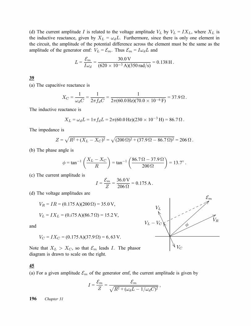
(d) The current amplitude I is related to the voltage amplitude VL by VL = IXL, where XL isthe inductive reactance, given by XL = !dL. Furthermore, since there is only one element inthe circuit, the amplitude of the potential difference across the element must be the same as theamplitude of the generator emf: VL = Em. Thus Em = I!dL and
L =EmI!d
=30:0V
(620£ 10¡3 A)(350 rad=s) = 0:138H :
39(a) The capacitive reactance is
XC =1!dC
=1
2¼fdC=
12¼(60:0Hz)(70:0£ 10¡6 F) = 37:9 :
The inductive reactance is
XL = !dL = 1¼fdL = 2¼(60:0Hz)(230£ 10¡3 H) = 86:7 :The impedance is
Z =pR2 + (XL ¡XC)2 =
p(200)2 + (37:9¡ 86:7)2 = 206 :
(b) The phase angle is
Á = tan¡1µXL ¡XC
R
¶= tan¡1
µ86:7¡ 37:9
200
¶= 13:7± :
(c) The current amplitude is
I =EmZ=36:0V206
= 0:175A :
(d) The voltage amplitudes are
VR = IR = (0:175A)(200) = 35:0V,
VL = IXL = (0:i75A)(86:7) = 15:2V,
and
VC = IXC = (0:175A)(37:9) = 6; 63V.
Note that XL > XC , so that Em leads I . The phasordiagram is drawn to scale on the right.
.....................................................................................................................................................................................................................................................................................................................................................................
............................................................................................................................................................................................................................................................................................................................................................
......................
.....................................................................................................................................................................................................................
......................................................................................................................
.......................................................................................................................................
..........................
..........................
..........................
..........................
..........................
..........................
............
VR
EmVL
VC
VL ¡ VC Á
45(a) For a given amplitude Em of the generator emf, the current amplitude is given by
I =EmZ=
EmpR2 + (!dL¡ 1=!dC)2
;
196 Chapter 31

where R is the resistance, L is the inductance, C is the capacitance, and !d is the angularfrequency. To find the maximum, set the derivative with respect to !d equal to zero and solvefor !d. The derivative is
dI
d!d= ¡Em
£R2 + (!dL¡ 1=!dC)2
¤¡3=2 ∙!dL¡ 1
!dC
¸ ∙L +
1!2dC
¸:
The only factor that can equal zero is !dL ¡ (1=!dC) and it does for !d = 1=pLC. For the
given circuit,
!d =1pLC
=1p
(1:00H)(20:0£ 10¡6 F) = 224 rad=s :
(b) For this value of the angular frequency, the impedance is Z = R and the current amplitude is
I =EmR=30:0V5:00
= 6:00A :
(c) and (d) You want to find the values of !d for which I = Em=2R. This meansEmp
R2 + (!dL¡ 1=!dC)2=Em2R
:
Cancel the factors Em that appear on both sides, square both sides, and set the reciprocals of thetwo sides equal to each other to obtain
R2 +µ!dL¡ 1
!dC
¶2= 4R2 :
Thus µ!dL¡ 1
!dC
¶2= 3R2 :
Now take the square root of both sides and multiply by !dC to obtain
!2d (LC)§ !d³p3CR
´¡ 1 = 0 ;
where the symbol § indicates the two possible signs for the square root. The last equation is aquadratic equation for !d. Its solutions are
!d =§p3CR§
p3C2R2 + 4LC
2LC:
You want the two positive solutions. The smaller of these is
!2 =¡p3CR +
p3C2R2 + 4LC
2LC
=¡p3(20:0£ 10¡6 F)(5:00)2(1:00H)(20:0£ 10¡6 F)+p3(20:0£ 10¡6 F)2(5:00)2 + 4(1:00H)(20:0£ 10¡6 F)
2(1:00H)(20:0£ 10¡6 F)= 219 rad=s
Chapter 31 197

and the larger is
!1 =+p3CR +
p3C2R2 + 4LC2LC
=+p3(20:0£ 10¡6 F)(5:00)2(1:00H)(20:0£ 10¡6 F)+p3(20:0£ 10¡6 F)2(5:00)2 + 4(1:00H)(20:0£ 10¡6 F)
2(1:00H)(20:0£ 10¡6 F)= 228 rad=s :
(e) The fractional width is
!1 ¡ !2!0
=228 rad=s¡ 219 rad=s
224 rad=s= 0:04 :
49Use the expressions found in Problem 31–45:
!1 =+p3CR +
p3C2R2 + 4LC2LC
and
!2 =¡p3CR +
p3C2R2 + 4LC
2LC:
Also use! =
1pLC
:
Thus¢!d!
=!1 ¡ !2!
=2p3CR
pLC
2LC= R
r3CL:
55(a) The impedance is given by
Z =pR2 + (XL ¡XC)2 ;
where R is the resistance, XL is the inductive reactance, and XC is the capacitive reactance.Thus
Z =p(12:0)2 + (1:30¡ 0)2 = 12:1 :
(b) The average rate at which energy is supplied to the air conditioner is given by
Pavg =E2rmsZ
cosÁ ;
198 Chapter 31
where cosÁ is the power factor. Now
cosÁ =R
Z=1212:1
= 0:992 ;
soPavg =
∙(120V)2
12:1
¸(0:992) = 1:18£ 103 W :
57(a) The power factor is cosÁ, where Á is the phase angle when the current is written i =I sin(!dt¡ Á). Thus Á = ¡42:0± and cosÁ = cos(¡42:0±) = 0:743.(b) Since Á < 0, !dt¡ Á > !dt and the current leads the emf.(c) The phase angle is given by tanÁ = (XL ¡ XC)=R, where XL is the inductive reactance,XC is the capacitive reactance, and R is the resistance. Now tanÁ = tan(¡42:0±) = ¡0:900, anegative number. This means XL ¡ XC is negative, or XC > XL. The circuit in the box ispredominantly capacitive.(d) If the circuit is in resonance, XL is the same as XC , tanÁ is zero, and Á would be zero.Since Á is not zero, we conclude the circuit is not in resonance.(e), (f), and (g) Since tanÁ is negative and finite, neither the capacitive reactance nor the resistanceis zero. This means the box must contain a capacitor and a resistor. The inductive reactance maybe zero, so there need not be an inductor. If there is an inductor, its reactance must be less thanthat of the capacitor at the operating frequency.(h) The average power is
Pavg =12EmI cosÁ = 12(75:0V)(1:20A)(0:743) = 33:4W :
(i) The answers above depend on the frequency only through the phase angle Á, which is given.If values are given for R, L, and C, then the value of the frequency would also be needed tocompute the power factor.
63(a) If Np is the number of primary turns and Ns is the number of secondary turns, then
Vs =NsNp
Vp =µ10500
¶(120V) = 2:4V :
(b) and (c) The current in the secondary is given by Ohm’s law:
Is =VsRs=2:4V15
= 0:16A :
The current in the primary is
Ip =NsNp
Is =µ10500
¶(0:16A) = 3:2£ 10¡3 A :
Chapter 31 199

67Use the trigonometric identity, found in Appendix E,
sin®¡ sin¯ = 2 sinµ®¡ ¯2
¶cosµ® + ¯2
¶;
where ® and ¯ are any two angles. Thus
V1¡V2 = A sin(!dt)¡A sin(!dt¡ 120±) = 2A sin(120±) cos(!dt¡ 60±) =p3A cos(!dt¡ 60±) ;
where sin(120±) =p3=2 was used. Similarly,
V1¡V3 = A sin(!dt)¡A sin(!dt¡240±) = 2A sin(240±) cos(!dt¡120±) = ¡p3A cos(!dt¡120±) ;
where sin(240±) = ¡p3=2 was used, and
V2 ¡ V3 = A sin(!dt¡ 120±)¡A sin(!dt¡ 240±) = 2A sin(120±) cos(!dt¡ 180±)=p3A cos(!dt¡ 180±) :
All of these are sinusoidal functions of !d and all have amplitudes ofp3A.
71(a) Let VC be the maximum potential difference across the capacitor, VL be the maximum potentialdifference across the inductor, and VR be the maximum potential difference across the resistor.Then the phase constant Á is
tan¡1µVL ¡ VCVR
¶= tan¡1
µ2:00VR ¡ VR
VR
¶= tan¡1(1:00) = 45:0± :
(b) Since the maximum emf is related to the current amplitude by Em = IZ, where Z is theimpedance and R = Z cosÁ,
R =Em cosÁ
I=(30:0V) cos 45±
300£ 10¡3 A = 70:7 :
73
(a) The frequency of oscillation of an LC circuit is f = 1=2¼pLC, where L is the inductance
and C is the capacitance. Thus
L =1
4¼2f 2C=
14¼2(10:4£ 103 Hz)2(340£ 10¡6 F) = 6:89£ 10
¡7 H :
(b) The total energy is U = 12LI
2, where I is the current amplitude. Thus U = 12(6:89 £
10¡7 H)(7:20£ 10¡3 A)2 = 1:79£ 10¡11 J.200 Chapter 31

(c) The total energy is also given by U = Q2=2C, where Q is the charge amplitude. ThusQ =
p2UC =
p2(1:79£ 10¡11 J)(340£ 10¡6 F) = 1:10£ 10¡7 C.
83(a) The total energy U of the circuit is the sum of the energy UE stored in the capacitor andthe energy UB stored in the inductor at the same time. Since UB = 2:00UE , the total energy isU = 3:00UE . Now U = Q2=2C and UE = q2=2C, where Q is the maximum charge, q is thecharge when the magnetic energy is twice the electrical energy, and C is the capacitance. ThusQ2=2C = 3:00q2=2C and q = Q=
p3:00 = 0:577Q.
(b) If the capacitor has maximum charge at time t = 0, then q = Q cos(!t), where ! is the angularfrequency of oscillation. This means !t = cos¡1(0:577) = 0:964 rad. Since ! = 2¼=T , where Tis the period,
t =0:9642¼
T = 0:153T :
85(a) The energy stored in a capacitor is given by UE = q2=2C, where q is the charge and C is thecapacitance. Now q2 is periodic with a period of T=2, where T is the period of the driving emf,so UE has the same value at the beginning and end of each cycle. Actually UE has the samevalue at the beginning and end of each half cycle.(b) The energy stored in an inductor is given by Li2=2, where i is the current and L is theinductance. The square of the current is periodic with a period of T=2, so it has the same valueat the beginning and end of each cycle.(c) The rate with which the driving emf device supplies energy is
PE = iE = IEm sin(!dt) sin(!dt¡ Á) ;where I is the current amplitude, Em is the emf amplitude, ! is the angular frequency, and Á isa phase constant. The energy supplied over a cycle is
EE =Z T
0PE dt = IEm
Z T
0sin(!dt) sin(!dt¡ Á) dt
= IEmZ T
0sin(!dt) [sin(!dt)cos(Á)¡ cos(!dt) sin(Á)] dt ;
where the trigonometric identity sin(®¡¯) = sin® cos¯¡cos® sin¯ was used. Now the integralof sin2(!dt) over a cycle is T=2 and the integral of sin(!dt) cos(!dt) over a cycle is zero, soEE = 1
2IEm cosÁ.(d) The rate of energy dissipation in a resistor is given by
PR = i2R = I2 sin2(!dt¡ Á)and the energy dissipated over a cycle is
ER = I2Z T
0sin2(!dt¡ Á) dt = 1
2I2RT :
(e) Now Em = IZ, where Z is the impedance, and R = Z cosÁ, so EE = 12I2TZ cosÁ =
12I2RT = ER.
Chapter 31 201

Chapter 32
3
(a) Use Gauss’ law for magnetism:H~B ¢ d ~A = 0. Write H ~B ¢ d ~A = ©1 + ©2 + ©C , where ©1
is the magnetic flux through the first end mentioned, ©2 is the magnetic flux through the secondend mentioned, and ©C is the magnetic flux through the curved surface. Over the first end, themagnetic field is inward, so the flux is ©1 = ¡25:0¹Wb. Over the second end, the magneticfield is uniform, normal to the surface, and outward, so the flux is ©2 = AB = ¼r2B, where Ais the area of the end and r is the radius of the cylinder. Its value is
©2 = ¼(0:120m)2(1:60£ 10¡3 T) = +7:24£ 10¡5 Wb = +72:4¹Wb :Since the three fluxes must sum to zero,
©C = ¡©1 ¡ ©2 = 25:0¹Wb¡ 72:4¹Wb = ¡47:4¹Wb :(b) The minus sign indicates that the flux is inward through the curved surface.
5Consider a circle of radius r (= 6:0mm), between the plates and with its center on the axis ofthe capacitor. The current through this circle is zero, so the Ampere-Maxwell law becomesI
~B ¢ d~s = ¹0²0d©Edt
;
where ~B is the magnetic field at points on the circle and ©E is the electric flux through thecircle. The magnetic field is tangent to the circle at all points on it, so
H~B ¢ d~s = 2¼rB. The
electric flux through the circle is ©E = ¼R2E, where R (= 3:0mm) is the radius of a capacitorplate. When these substitutions are made, the Ampere-Maxwell law becomes
2¼rB = ¹0²0¼R2dE
dt:
Thus
dE
dt=2rB¹0²0R2
=2(6:0£ 10¡3 m)(2:0£ 10¡7 T)
(4¼ £ 10¡7 H=m)(8:85£ 10¡12 Fm)(3:0£ 10¡3 m)2 = 2:4£ 1013 V=m ¢ s :
13The displacement current is given by
id = ²0AdE
dt;
202 Chapter 32
where A is the area of a plate and E is the magnitude of the electric field between the plates.The field between the plates is uniform, so E = V=d, where V is the potential difference acrossthe plates and d is the plate separation. Thus
id =²0A
d
dV
dt:
Now ²0A=d is the capacitance C of a parallel-plate capacitor without a dielectric, so
id = CdV
dt:
21(a) For a parallel-plate capacitor, the charge q on the positive plate is given by q = (²0A=d)V ,where A is the plate area, d is the plate separation, and V is the potential difference between theplates. In terms of the electric field E between the plates, V = Ed, so q = ²0AE = ²0©E , where©E is the total electric flux through the region between the plates. The true current into thepositive plate is i = dq=dt = ²0 d©E=dt = id total, where id total is the total displacement currentbetween the plates. Thus id total = 2:0A.(b) Since id total = ²0 d©E=dt = ²0AdE=dt,
dE
dt=id total²0A
=2:0A
(8:85£ 10¡12 F=m)(1:0m)2 = 2:3£ 1011 V=m ¢ s :
(c) The displacement current is uniformly distributed over the area. If a is the area enclosed bythe dashed lines and A is the area of a plate, then the displacement current through the dashedpath is
id enc =a
Aid total =
(0:50m)2
(1:0m)2(2:0A) = 0:50A :
(d) According to Maxwell’s law of induction,I~B ¢ d~s = ¹0id enc = (4¼ £ 10¡7 H=m)(0:50A) = 6:3£ 10¡7 T ¢m :
Notice that the integral is around the dashed path and the displacement current on the rightside of the Maxwell’s law equation is the displacement current through that path, not the totaldisplacement current.
35(a) The z component of the orbital angular momentum is given by Lorb, z = m`h=2¼, where h isthe Planck constant. Since m` = 0, Lorb, z = 0.(b) The z component of the orbital contribution to the magnetic dipole moment is given by¹orb, z = ¡m`¹B , where ¹B is the Bohr magneton. Since m` = 0, ¹orb, z = 0.(c) The potential energy associated with the orbital contribution to the magnetic dipole momentis given by U = ¡¹orb, zBext, where Bext is the z component of the external magnetic field. Since¹orb, z = 0, U = 0.
Chapter 32 203

(d) The z component of the spin magnetic dipole moment is either +¹B or ¡¹B , so the potentialenergy is either
U = ¡¹BBext = ¡(9:27£ 10¡24 J=T)(35£ 10¡3 T) = ¡3:2£ 10¡25 J :
or U = +3:2£ 10¡25 J.(e) Substitute m` into the equations given above. The z component of the orbital angularmomentum is
Lorb, z =m`h
2¼=(¡3)(6:626£ 10¡34 J ¢ s)
2¼= ¡3:2£ 10¡34 J ¢ s :
(f) The z component of the orbital contribution to the magnetic dipole moment is
¹orb, z = ¡m`¹B = ¡(¡3)(9:27£ 10¡24 J=T) = 2:8£ 10¡23 J=T :
(g) The potential energy associated with the orbital contribution to the magnetic dipole momentis
U = ¡¹orb, zBext = ¡(2:78£ 10¡23 J=T)(35£ 10¡3 T) = ¡9:7£ 10¡25 J :(h) The potential energy associated with spin does not depend on m`. It is §3:2£ 10¡25 J.
39The magnetization is the dipole moment per unit volume, so the dipole moment is given by¹ = MV , where M is the magnetization and V is the volume of the cylinder. Use V = ¼r2L,where r is the radius of the cylinder and L is its length. Thus
¹ =M¼r2L = (5:30£ 103 A=m)¼(0:500£ 10¡2 m)2(5:00£ 10¡2 m) = 2:08£ 10¡2 J=T :
45(a) The number of atoms per unit volume in states with the dipole moment aligned with themagnetic field is N+ = Ae¹B=kT and the number per unit volume in states with the dipolemoment antialigned is N¡ = Ae¡¹B=kT , where A is a constant of proportionality. The totalnumber of atoms per unit volume is N = N+ +N¡ = A
¡e¹B=kT + e¡¹B=kT
¢. Thus
A =N
e¹B=kT + e¡¹B=kT:
The magnetization is the net dipole moment per unit volume. Subtract the magnitude of the totaldipole moment per unit volume of the antialigned moments from the total dipole moment per unitvolume of the aligned moments. The result is
M =N¹e¹B=kT ¡N¹e¡¹B=kT
e¹B=kT + e¡¹B=kT=N¹
¡e¹B=kT ¡ e¡¹B=kT ¢e¹B=kT + e¡¹B=kT
= N¹ tanh(¹B=kT ) :
204 Chapter 32

(b) If ¹B ¿ kT , then e¹B=kT ¼ 1 +¹B=kT and e¡¹B=kT ¼ 1¡¹B=kT . (See Appendix E forthe power series expansion of the exponential function.) The expression for the magnetizationbecomes
M ¼ N¹£(1 + ¹B=kT )¡ (1¡ ¹B=kT )¤(1 + ¹B=kT ) + (1¡ ¹B=kT ) =
N¹2B
kT:
(c) If ¹B À kT , then e¡¹B=kT is negligible compared to e¹B=kT in both the numerator anddenominator of the expression for M . Thus
M ¼ N¹e¹B=kT
e¹B=kT= N¹ :
(d) The expression for M predicts that it is linear in B=kT for ¹B=kT small and independentof B=kT for ¹B=kT large. The figure agrees with these predictions.
47(a) The field of a dipole along its axis is given by Eq. 29–27:
~B =¹02¼
~¹
z3;
where ¹ is the dipole moment and z is the distance from the dipole. Thus the magnitude of themagnetic field is
B =(4¼ £ 10¡7 T ¢m=A)(1:5£ 10¡23 J=T)
2¼(10£ 10¡9 m)3 = 3:0£ 10¡6 T :
(b) The energy of a magnetic dipole with dipole moment ~¹ in a magnetic field ~B is given byU = ¡~¹ ¢ ~B = ¡¹B cosÁ, where Á is the angle between the dipole moment and the field. Theenergy required to turn it end for end (from Á = 0± to Á = 180±) is
¢U = ¡¹B(cos 180± ¡ cos 0±) = 2¹B = 2(1:5£ 10¡23 J=T)(3:0£ 10¡6 T)= 9:0£ 10¡29 J = 5:6£ 10¡10 eV :
The mean kinetic energy of translation at room temperature is about 0:04 eV (see Eq. 19–24 orSample Problem 32–3). Thus if dipole-dipole interactions were responsible for aligning dipoles,collisions would easily randomize the directions of the moments and they would not remainaligned.
53(a) If the magnetization of the sphere is saturated, the total dipole moment is ¹total = N¹, whereN is the number of iron atoms in the sphere and ¹ is the dipole moment of an iron atom. Wewish to find the radius of an iron sphere with N iron atoms. The mass of such a sphere is Nm,where m is the mass of an iron atom. It is also given by 4¼½R3=3, where ½ is the density ofiron and R is the radius of the sphere. Thus Nm = 4¼½R3=3 and
N =4¼½R3
3m:
Chapter 32 205

Substitute this into ¹total = N¹ to obtain
¹total =4¼½R3¹3m
:
Solve for R and obtain
R =∙3m¹total4¼½¹
¸1=3:
The mass of an iron atom is
m = 56 u = (56 u)(1:66£ 10¡27 kg=u) = 9:30£ 10¡26 kg :So
R =
"3(9:30£ 10¡26 kg)(8:0£ 1022 J=T)4¼(14£ 103 kg=m3)(2:1£ 10¡23 J=T)
#1=3= 1:8£ 105 m :
(b) The volume of the sphere is
Vs =4¼3R3 =
4¼3(1:82£ 105 m)3 = 2:53£ 1016 m3
and the volume of Earth is
Ve =4¼3(6:37£ 106 m)3 = 1:08£ 1021 m3 ;
so the fraction of Earth’s volume that is occupied by the sphere is
2:53£ 1016 m31:08£ 1021 m3 = 2:3£ 10
¡5 :
The radius of Earth was obtained from Appendix C.
55(a) The horizontal and vertical directions are perpendicular to each other, so the magnitude ofthe field is
B =qB2h +B2v =
¹0¹
4¼r3
qcos2 ¸m + 4 sin2 ¸m =
¹0¹
4¼r3
q1¡ sin2 ¸m + 4 sin2 ¸m
=¹0¹
4¼r3
q1 + 3 sin2 ¸m ;
where the trigonometric identity cos2 ¸m = 1¡ sin2 ¸m was used.(b) The tangent of the inclination angle is
tanÁi =BvBh
=µ
¹0¹
2¼r3 sin¸m
¶ µ4¼r3
¹0¹ cos¸m=2 sin¸mcos¸m
¶= 2 tan¸m ;
where tan¸m = (sin¸m)=(cos¸m) was used.
61(a) The z component of the orbital angular momentum can have the values Lorb,z = m`h=2¼,where m` can take on any integer value from ¡3 to +3, inclusive. There are seven such values(¡3, ¡2, ¡1, 0, +1, +2, and +3).206 Chapter 32
(b) The z component of the orbital magnetic moment is given by ¹orb,z = ¡m`eh=4¼m, wherem is the electron mass. Since there is a different value for each possible value of m`, there areseven different values in all.(c) The greatest possible value of Lorb,z occurs if m` = +3 is 3h=2¼.(d) The greatest value of ¹orb, z is 3eh=4¼m.(e) Add the orbital and spin angular momenta: Lnet,z = Lorb,z +Ls;z = (m`h=2¼)+ (msh=2¼). Toobtain the maximum value, setm` equal to +3 andms equal to +12 . The result is Lnet,z = 3:5h=2¼.(f) Write Lnet,z =Mh=2¼, where M is half an odd integer. M can take on all such values from¡3:5 to +3:5. There are eight of these: ¡3:5, ¡2:5, ¡1:5, ¡0:5, +0:5, +1:5, +2:5, and +3:5.
Chapter 32 207

Chapter 33
5If f is the frequency and ¸ is the wavelength of an electromagnetic wave, then f¸ = c. Thefrequency is the same as the frequency of oscillation of the current in the LC circuit of thegenerator. That is, f = 1=2¼
pLC, where C is the capacitance and L is the inductance. Thus
¸
2¼pLC
= c :
The solution for L is
L =¸2
4¼2Cc2=
(550£ 10¡9 m)24¼2(17£ 10¡12 F)(3:00£ 108 m=s)2 = 5:00£ 10
¡21 H :
This is exceedingly small.
21The plasma completely reflects all the energy incident on it, so the radiation pressure is given bypr = 2I=c, where I is the intensity. The intensity is I = P=A, where P is the power and A isthe area intercepted by the radiation. Thus
pr =2PAc
=2(1:5£ 109 W)
(1:00£ 10¡6 m2)(3:00£ 108 m=s) = 1:0£ 107 Pa = 10MPa :
23Let f be the fraction of the incident beam intensity that is reflected. The fraction absorbed is1¡f . The reflected portion exerts a radiation pressure of pr = (2fI0)=c and the absorbed portionexerts a radiation pressure of pa = (1 ¡ f)I0=c, where I0 is the incident intensity. The factor 2enters the first expression because the momentum of the reflected portion is reversed. The totalradiation pressure is the sum of the two contributions:
ptotal = pr + pa =2fI0 + (1¡ f )I0
c=(1 + f)I0
c:
To relate the intensity and energy density, consider a tube with length ` and cross-sectionalarea A, lying with its axis along the propagation direction of an electromagnetic wave. Theelectromagnetic energy inside is U = uA`, where u is the energy density. All this energy willpass through the end in time t = `=c so the intensity is
I =U
At=uA`c
A`= uc :
Thus u = I=c. The intensity and energy density are inherently positive, regardless of the propa-gation direction.
208 Chapter 33

For the partially reflected and partially absorbed wave, the intensity just outside the surface isI = I0 + fI0 = (1 + f )I0, where the first term is associated with the incident beam and the secondis associated with the reflected beam. The energy density is, therefore,
u =I
c=(1 + f )I0
c;
the same as radiation pressure.
25(a) Since c = ¸f , where ¸ is the wavelength and f is the frequency of the wave,
f =c
¸=3:00£ 108 m=s
3:0m= 1:0£ 108 Hz :
(b) The angular frequency is
! = 2¼f = 2¼(1:0£ 108 Hz) = 6:3£ 108 rad=s :(c) The angular wave number is
k =2¼¸=2¼3:0m
= 2:1 rad=m :
(d) The magnetic field amplitude is
Bm =Emc=
300V=m3:00£ 108 m=s = 1:00£ 10
¡6 T :
(e) ~B must be in the positive z direction when ~E is in the positive y direction in order for ~E£ ~Bto be in the positive x direction (the direction of propagation).(f) The time-averaged rate of energy flow or intensity of the wave is
I =E2m2¹0c
=(300V=m)2
2(4¼ £ 10¡7 H=m)(3:00£ 108 m=s) = 1:2£ 102 W=m2 :
(g) Since the sheet is perfectly absorbing, the rate per unit area with which momentum is deliveredto it is I=c, so
dp
dt=IA
c=(119W=m2)(2:0m2)3:00£ 108 m=s = 8:0£ 10¡7 N :
(h) The radiation pressure is
pr =dp=dt
A=8:0£ 10¡7 N2:0m2
= 4:0£ 10¡7 Pa :
27If the beam carries energy U away from the spaceship, then it also carries momentum p = U=caway. Since the total momentum of the spaceship and light is conserved, this is the magnitude of
Chapter 33 209
the momentum acquired by the spaceship. If P is the power of the laser, then the energy carriedaway in time t is U = Pt. Thus p = Pt=c and, if m is mass of the spaceship, its speed is
v =p
m=Pt
mc=(10£ 103 W)(1d)(8:64£ 104 s=d)(1:5£ 103 kg)(3:00£ 108 m=s) = 1:9£ 10¡3 m=s = 1:9mm=s :
35Let I0 be in the intensity of the unpolarized light that is incident on the first polarizing sheet.Then the transmitted intensity is I1 = 1
2I0 and the direction of polarization of the transmitted lightis µ1 (= 40±) counterclockwise from the y axis in the diagram.The polarizing direction of the second sheet is µ2 (= 20±) clockwise from the y axis so the anglebetween the direction of polarization of the light that is incident on that sheet and the polarizingdirection of the of the sheet is 40± + 20± = 60±. The transmitted intensity is
I2 = I1 cos2 60± =12I0 cos2 60±
and the direction of polarization of the transmitted light is 20± clockwise from the y axis.The polarizing direction of the third sheet is µ3 (= 40±) counterclockwise from the y axis so theangle between the direction of polarization of the light incident on that sheet and the polarizingdirection of the sheet is 20± + 40± = 60±. The transmitted intensity is
I3 = I2 cos2 60± =12I0 cos4 60± = 3:1£ 10¡2 :
3:1% of the light’s initial intensity is transmitted.
43(a) The rotation cannot be done with a single sheet. If a sheet is placed with its polarizingdirection at an angle of 90± to the direction of polarization of the incident radiation, no radiationis transmitted.It can be done with two sheets. Place the first sheet with its polarizing direction at some angleµ, between 0 and 90±, to the direction of polarization of the incident radiation. Place the secondsheet with its polarizing direction at 90± to the polarization direction of the incident radiation.The transmitted radiation is then polarized at 90± to the incident polarization direction. Theintensity is I0 cos2 µ cos2(90±¡ µ) = I0 cos2 µ sin2 µ, where I0 is the incident radiation. If µ is not0 or 90±, the transmitted intensity is not zero.(b) Consider n sheets, with the polarizing direction of the first sheet making an angle of µ = 90±=nwith the direction of polarization of the incident radiation and with the polarizing direction ofeach successive sheet rotated 90±=n in the same direction from the polarizing direction of theprevious sheet. The transmitted radiation is polarized with its direction of polarization makingan angle of 90± with the direction of polarization of the incident radiation. The intensity isI = I0 cos2n(90±=n). You want the smallest integer value of n for which this is greater than0:60I0.
210 Chapter 33

Start with n = 2 and calculate cos2n(90±=n). If the result is greater than 0:60, you have obtainedthe solution. If it is less, increase n by 1 and try again. Repeat this process, increasing n by 1each time, until you have a value for which cos2n(90±=n) is greater than 0:60. The first one willbe n = 5.
55Look at the diagram on the right. The two angles la-beled ® have the same value. µ2 is the angle of re-fraction. Because the dotted lines are perpendicular tothe prism surface µ2 + ® = 90± and ® = 90± ¡ µ2.Because the interior angles of a triangle sum to 180±,180± ¡ 2µ2 + Á = 180± and µ2 = Á=2.
..........................................................................................................................................................................................................................................................................................................................................................................................................................................................................................................................................................................................................................................................................................................................................................................................................................................................................................................................................................................
...................................................................................................................................................................................................................................................................................................................................................................................................................................................................
............. ............. ............. ............. ............. ............. ............ ..........................
..........................
..........................
............
Á
µ µµ2 µ2® ®
Now look at the next diagram and consider the triangleformed by the two normals and the ray in the interior.The two equal interior angles each have the value µ¡µ2.Because the exterior angle of a triangle is equal to thesum of the two opposite interior angles, à = 2(µ ¡ µ2)and µ = µ2+Ã=2. Upon substitution for µ2 this becomesµ = (Á + Ã)=2.
..........................................................................................................................................................................................................................................................................................................................................................................................................................................................................................................................................................................................................................................................................................................................................................................................................................................................................................................................................................................
...................................................................................................................................................................................................................................................................................................................................................................................................................................................................
............. ............. ............. ............. ............. ............. ............ ..........................
..........................
..........................
............
..........................
..........................
..........................
..........................
......................
..........................
..........................
.............
Á
µ µµ2 µ2
Ã
According to the law of refraction the index of refraction of the prism material is
n =sin µsin µ2
=sin(Á + Ã)=2sinÁ=2
:
65(a) No refraction occurs at the surface ab, so the angle of incidence at surface ac is 90± ¡ Á.For total internal reflection at the second surface, ng sin(90± ¡ Á) must be greater than na.Here ng is the index of refraction for the glass and na is the index of refraction for air. Sincesin(90± ¡ Á) = cosÁ, you want the largest value of Á for which ng cosÁ ¸ na. Recall thatcosÁ decreases as Á increases from zero. When Á has the largest value for which total internalreflection occurs, then ng cosÁ = na, or
Á = cos¡1µnang
¶= cos¡1
µ11:52
¶= 48:9± :
The index of refraction for air was taken to be unity.(b) Replace the air with water. If nw (= 1:33) is the index of refraction for water, then the largestvalue of Á for which total internal reflection occurs is
Á = cos¡1µnwng
¶= cos¡1
µ1:331:52
¶= 29:0± :
Chapter 33 211

69The angle of incidence µB for which reflected light is fully polarized is given by Eq. 33–49 ofthe text. If n1 is the index of refraction for the medium of incidence and n2 is the index ofrefraction for the second medium, then µB = tan¡1
¡n2=n1
¢= tan¡1
¡1:53=1:33
¢= 63:8±.
73Let µ1 (= 45±) be the angle of incidence at the first surface and µ2 be the angle of refractionthere. Let µ3 be the angle of incidence at the second surface. The condition for total internalreflection at the second surface is n sin µ3 ¸ 1. You want to find the smallest value of the indexof refraction n for which this inequality holds.The law of refraction, applied to the first surface, yields n sin µ2 = sin µ1. Consideration of thetriangle formed by the surface of the slab and the ray in the slab tells us that µ3 = 90±¡µ2. Thus thecondition for total internal reflection becomes 1 ∙ n sin(90±¡µ2) = n cos µ2. Square this equationand use sin2 µ2 + cos2 µ2 = 1 to obtain 1 ∙ n2(1 ¡ sin2 µ2). Now substitute sin µ2 = (1=n) sin µ1to obtain
1 ∙ n2Ã1¡ sin
2 µ1n2
!= n2 ¡ sin2 µ1 :
The largest value of n for which this equation is true is the value for which 1 = n2 ¡ sin2 µ1.Solve for n:
n =q1 + sin2 µ1 =
p1 + sin2 45± = 1:22 :
75Let µ be the angle of incidence and µ2 be the angleof refraction at the left face of the plate. Let nbe the index of refraction of the glass. Then, thelaw of refraction yields sin µ = n sin µ2. The angleof incidence at the right face is also µ2. If µ3 isthe angle of emergence there, then n sin µ2 = sin µ3.Thus sin µ3 = sin µ and µ3 = µ. The emerging ray isparallel to the incident ray.You wish to derive an expression for x in termsof µ. If D is the length of the ray in the glass,then D cos µ2 = t and D = t= cos µ2. The angle ®in the diagram equals µ ¡ µ2 and x = D sin® =D sin(µ ¡ µ2). Thus
x =t sin(µ ¡ µ2)cos µ2
:
á¡¡¡ t ¡¡¡¡!.................................................................................................................................................................................................................................................................................................................................................................................
................................................................................. .................
..................................................................................................
..........................................................................................................................................................................................................................................
..........................
..........................
..
µ
µ2
µ2
µ3x
®
If all the angles µ, µ2, µ3, and µ¡µ2 are small and measured in radians, then sin µ ¼ µ, sin µ2 ¼ µ2,sin(µ ¡ µ2) ¼ µ ¡ µ2, and cos µ2 ¼ 1. Thus x ¼ t(µ ¡ µ2). The law of refraction applied to the212 Chapter 33

point of incidence at the left face of the plate is now µ ¼ nµ2, so µ2 ¼ µ=n and
x ¼ tµµ ¡ µ
n
¶=(n¡ 1)tµ
n:
77The time for light to travel a distance d in free space is t = d=c, where c is the speed of light(3:00£ 108 m=s).(a) Take d to be 150 km = 150£ 103 m. Then,
t =d
c=150£ 103 m3:00£ 108 m=s = 5:00£ 10
¡4 s :
(b) At full moon, the Moon and Sun are on opposite sides of Earth, so the distance traveled bythe light is d = (1:5 £ 108 km) + 2(3:8 £ 105 km) = 1:51 £ 108 km = 1:51 £ 1011 m. The timetaken by light to travel this distance is
t =d
c=1:51£ 1011 m3:00£ 108 m=s = 500 s = 8:4min :
The distances are given in the problem.(c) Take d to be 2(1:3£ 109 km) = 2:6£ 1012 m. Then,
t =d
c=2:6£ 1012 m3:00£ 108 m=s = 8:7£ 10
3 s = 2:4 h :
(d) Take d to be 6500 ly and the speed of light to be 1:00 ly=y. Then,
t =d
c=6500 ly1:00 ly=y
= 6500 y :
The explosion took place in the year 1054¡ 6500 = ¡5446 or B.C. 5446.
79(a) The amplitude of the magnetic field is B = E=c = (5:00V=m)=(3:00 £ 108 m=s) = 1:67 £10¡8 T. According to the argument of the trigonometric function in the expression for the electricfield, the wave is moving in the negative z direction and the electric field is parallel to the yaxis. In order for ~E £ ~B to be in the negative z direction, ~B must be in the positive x directionwhen ~E is in the positive y direction. Thus
Bx = (1:67£ 10¡8 T) sin[(1:00£ 106 m¡1)z + !t]is the only nonvanishing component of the magnetic field.The angular wave number is k = 1:00 £ 106 m¡1 so the angular frequency is ! = kc = (1:00£106 m¡1)(3:00£ 108 m=s) = 3:00£ 1014 s¡1 and
Bx = (1:67£ 10¡8 T) sin[(1:00£ 106 m¡1)z + (3:00£ 1014 s¡1)t] :(b) The wavelength is ¸ = 2¼=k = 2¼=(1:00£ 106 m¡1) = 6:28£ 10¡6 m.
Chapter 33 213

(c) The period is T = 2¼=! = 2¼=(3:00£ 1014 s¡1) = 2:09£ 10¡14 s.(d) The intensity of this wave is I = E2m=2¹0c = (5:00V=m)2=2(4¼£10¡7 H=m)(3:00£108 m=s =0:0332W=m2. (f) A wavelength of 6:28£ 10¡6 m places this wave in the infrared portion of theelectromagnetic spectrum. See Fig. 33-1.
83(a) The power is the same through any hemisphere centered at the source. The area of a hemi-sphere of radius r is A = 2¼r2. In this case r is the distance from the source to the aircraft.Thus the intensity at the aircraft is I = P=A = P=2¼r2 = (180 £ 103 W)=2¼(90 £ 103 m)2 =3:5£ 10¡6 W=m2.(b) The power of the reflection is the product of the intensity at the aircraft and the cross sectionof the aircraft: Pr = (3:5£ 10¡6 W=m2)(0:22m2) = 7:8£ 10¡7 W.(c) The intensity at the detector is Pr=2¼r2 = (7:8 £ 10¡7 W)=2¼(90 £ 103 m)2 = 1:5 £10¡17 W=m2.(d) Since the intensity is given by I = E2m=2¹0c,
Em =p2¹0cI =
q2(4¼ £ 10¡7 H=m)(3:00£ 108 m=s)(1:5£ 10¡17 W=m2) = 1:1£ 10¡7 V=m :
(e) The rms value of the magnetic field is Brms = Em=p2c = (1:1 £ 10¡7 V=m)=(p2)(3:00 £
108 m=s) = 2:5£ 10¡16 T.
91The critical angle for total internal reflection is given by µc = sin¡1(1=n). For n = 1:456 thisangle is µc = 43:38± and for n = 1:470 it is µc = 42:86±.(a) An incidence angle of 42:00± is less than the critical angle for both red and blue light. Therefracted light is white.(b) An incidence angle of 43:10± is less than the critical angle for red light and greater than thecritical angle for blue light. Red light is refracted but blue light is not. The refracted light isreddish.(c) An incidence angle of 44:00± is greater than the critical angle for both red and blue light.Neither is refracted.
103(a) Take the derivative of the functions given for E and B, then substitute them into
@2E
@t2= c2
@2E
@x2and
@2B
@t2= c2
@2B
@x2:
The derivatives of E are @2E=@t2 = ¡!2Em sin(kx¡!t) and @2E=@x2 = ¡k2Em sin(kx¡!t),so the wave equation for the electric field yields !2 = c2k2. Since ! = ck the function satisfiesthe wave equation. Similarly, the derivatives of B are @2B=@t2 = ¡!2Bm sin(kx ¡ !t) and@2B=@x2 = ¡k2Bm sin(kx¡!t) and the wave equation for the magnetic field yields !2 = c2k2.Since ! = ck the function satisfies the wave equation.
214 Chapter 33

(b) Let u = kx§ !t and consider f to be a function of u, which in turn is a function of x andt. Then the chain rule of the calculus gives
@2E
@t2=d2f
du2
µ@u
@t
¶2=d2f
du2!2
and@2E
@x2=d2f
du2
µ@u
@x
¶2=d2f
du2k2 :
Substitution into the wave equation again yields !2 = c2k2, so the function obeys the waveequation. A similar analysis shows that the function for B also satisfies the wave equation.
Chapter 33 215

Chapter 34
5The light bulb is labeled O and its image is la-beled I on the digram to the right. Consider thetwo rays shown on the diagram to the right. Oneenters the water at A and is reflected from themirror at B. This ray is perpendicular to the wa-ter line and mirror. The second ray leaves thelightbulb at the angle µ, enters the water at C,where it is refracted. It is reflected from the mir-ror at D and leaves the water at E. At C the angleof incidence is µ and the angle of refraction isµ0. At D the angles of incidence and reflectionare both µ0. At E the angle of incidence is µ0 andthe angle of refraction is µ. The dotted lines thatmeet at I represent extensions of the emergingrays. Light appears to come from I. We want tocompute d3.
²O
²I
......................................................................................................................................................................................................................................................................................................................................
..........................................................................................................................................................................................................................................................................................................................................................................................................................................................................................................................................................................................................................................................................................................................................................................
.............
.............
.............
.............
.............
.............
.............
.............
............
..........................
..........................
..........................
..........................
..........................
..........................
..........................
..........................
A
B
C
D
E
µ
µ µ
µ0 µ0µ0 µ0
water line
mirror
"jd1j#"jd2j#"jd3j#
Consideration of the triangle OBE tells us that the distance d2 + d3 is L tan(90± ¡ µ) = L= tan µ,where L is the distance between A and E. Consideration of the triangle OBC tells us thatthe distance between A and C is d1 tan µ and consideration of the triangle CDE tells us thatthe distance between C and E is 2d2 tan µ0, so L = d1 tan µ + 2d2 tan µ0, d2 + d3 = (d1 tan µ +2d2 tan µ0)= tan µ, and
d3 =d1 tan µ + 2d2 tan µ0
tan µ¡ d2 :
Apply the law of refraction at point C: sin µ = n sin µ0, where n is the index of refraction ofwater. Since the angles µ and µ0 are small we may approximate their sines by their tangents andwrite tan µ = n tan µ0. Us this to substitute for tan µ in the expression for d3 to obtain
d3 =nd1 + 2d2
n¡ d2 = (1:33)(250 cm) + 2(200 cm)1:33
¡ 200 cm = 350 cm ;
where the index of refraction of water was taken to be 1:33.
11(a) The radius of curvature r and focal length f are positive for a concave mirror and are relatedby f = r=2, so r = 2(+12 cm) = +24 cm.
216 Chapter 34
(b) Since (1=p) + (1=i) = 1=f , where i is the image distance,
i =fp
p¡ f =(12 cm)(18 cm)18 cm¡ 12 cm = 36 cm :
(c) The magnification is m = ¡i=p = ¡(36 cm)=(18 cm = ¡2:0.(d) The value obtained for i is positive, so the image is real.(e) The value obtained for the magnification is negative, so the image is inverted.(f) Real images are formed by mirrors on the same side as the object. Since the image here isreal it is on the same side of the mirror as the object.
9(a) The radius of curvature r and focal length f are positive for a concave mirror and are relatedby f = r=2, so r = 2(+18 cm) = +36 cm.(b) Since (1=p) + (1=i) = 1=f , where i is the image distance,
i =fp
p¡ f =(18 cm)(12 cm)12 cm¡ 18 cm = ¡36 cm :
(c) The magnification is m = ¡i=p = ¡(¡36 cm)=(12 cm = 3:0.(d) The value obtained for i is negative, so the image is virtual.(e) The value obtained for the magnification is positive, so the image is not inverted.(f) Real images are formed by mirrors on the same side as the object and virtual images areformed on the opposite side. Since the image here is virtual it is on the opposite side of themirror from the object.
15(a) The radius of curvature r and focal length f are negative for a convex mirror and are relatedby f = r=2, so r = 2(¡10 cm) = ¡20 cm.(b) Since (1=p) + (1=i) = 1=f , where i is the image distance,
i =fp
p¡ f =(¡10 cm)(8 cm)(8 cm)¡ (¡10 cm) = ¡4:44 cm :
(c) The magnification is m = ¡i=p = ¡(¡4:44 cm)=(8 cm = +0:56.(d) The value obtained for i is negative, so the image is virtual.(e) The value obtained for the magnification is positive, so the image is not inverted.(f) Real images are formed by mirrors on the same side as the object and virtual images areformed on the opposite side. Since the image here is virtual it is on the opposite side of themirror from the object
27Since the mirror is convex the radius of curvature is negative. The focal length is f = r=2 =(¡40 cm)=2 = ¡20 cm.
Chapter 34 217

Since (1=p) + (1=i) = (1=f ),
p =if
i¡ f :
This yields p = +5:0 cm if i = ¡4:0 cm and p = ¡3:3 cm if i = ¡4:0 cm. Since p must be positivewe select i = ¡4:0 cm and take p to be +5:0 cm.The magnification is m = ¡i=p = ¡(¡4:0 cm)=(5:0 cm) = +0:80. Since the image distance isnegative the image is virtual and on the opposite side of the mirror from the object. Since themagnification is positive the image is not inverted.
29Since the magnification m is m = ¡i=p, where p is the object distance and i is the imagedistance, i = ¡mp. Use this to substitute for i in (1=p) + (1=i) = (1=f ), where f is the focallength. The solve for p. The result is
p = fµ1¡ 1
m
¶= (§30 cm)
µ1¡ 1
0:20
¶= §120 cm :
Since p must be positive we must use the lower sign. Thus the focal length is ¡30 cm andthe radius of curvature is r = 2f == 60 cm. Since the focal length and radius of curvature arenegative the mirror is convex.The object distance is 1:2m and the image distance is i = ¡mp = ¡(0:20)(120 cm) = ¡24 cm.Since the image distance is negative the image is virtual and on the opposite side of the mirrorfrom the object. Since the magnification is positive the image is not inverted.
35Solve
n1p+n2i=n2 ¡ n1r
for r. the result is
r =ip(n2 ¡ n1)n1i + n2p
=(¡13 cm)(+10 cm)
((1:0)(¡13 cm) + (1:5)(+10 cm) = ¡33 cm :
Since the image distance is negative the image is virtual and appears on the same side of thesurface as the object.
37Solve
n1p+n2i=n2 ¡ n1r
for r. the result is
i =n2rp
(n2 ¡ n1)p¡ n1r =(1:0)(+30 cm)(+70 cm)
(1:0¡ 1:5)(+70 cm)¡ (1:5)(+30 cm) = ¡26 cm :
218 Chapter 34

Since the image distance is negative the image is virtual and appears on the same side of thesurface as the object.
41Use the lens maker’s equation, Eq. 34–10:
1f= (n¡ 1)
µ1r1¡ 1r2
¶;
where f is the focal length, n is the index of refraction, r1 is the radius of curvature of the firstsurface encountered by the light and r2 is the radius of curvature of the second surface. Sinceone surface has twice the radius of the other and since one surface is convex to the incominglight while the other is concave, set r2 = ¡2r1 to obtain
1f= (n¡ 1)
µ1r1+12r1
¶=3(n¡ 1)2r1
:
Solve for r1:r1 =
3(n¡ 1)f2
=3(1:5¡ 1)(60mm)
2= 45mm :
The radii are 45mm and 90mm.
47The object distance p and image distance i obey (1=p) + (1=i) = (1=f ), where f is the focallength. In addition, p+ i = L, where L (= 44 cm) is the distance from the slide to the screen. Usei = L¡ p to substitute for i in the first equation and obtain p2 ¡ pL + Lf = 0. The solution is
p =L§
pL2 ¡ 4Lf2
=(44 cm)§p4(44 cm)(11 cm)
2= 22 cm :
51The lens is diverging, so the focal length is negative. Solve (1=p) + (1=i) = (1=f ) for i. Theresult is
i =pf
p¡ f =(+8:0 cm)(¡12 cm)(8:0 cm)¡ (¡12 cm) = ¡4:8 cm :
The magnification is m = ¡i=p = ¡(¡4:8 cm)=(+8:0 cm) = 0:60. Since the image distance isnegative the image is virtual and appears on the same side of the lens as the object. Since themagnification is positive the image is not inverted.
55The lens is converging, so the focal length is positive. Solve (1=p) + (1=i) = (1=f ) for i. Theresult is
i =pf
p¡ f =(+45 cm)(+20 cm)(45 cm)¡ (+20 cm) = +36 cm :
Chapter 34 219

The magnification is m = ¡i=p = ¡(36 cm)=(45 cm) = ¡0:80. Since the image distance ispositive the image is real and appears on the opposite side of the lens from the object. Since themagnification is negative the image is inverted.
61The focal length is
f =r1r2
(n¡ 1)(r2 ¡ r1) =(+30 cm)(¡42 cm)
(1:55¡ 1)[(¡42 cm)¡ (+30 cm)] = +31:8 cm :
Solve (1=p) + (1=i) = (1=f ) for i. the result is
i =pf
p¡ f =(+75 cm)(+31:8 cm)(+75 cm)¡ (+31:8 cm) = 55 cm :
The magnification is m = ¡i=p = ¡(55 cm)=(75 cm) = ¡0:73.Since the image distance is positive the image is real and on the opposite side of the lends fromthe object. Since the magnification is negative the image is inverted.
75Since m = ¡i=p, i = ¡mp = ¡(+1:25)(+16 cm) = ¡20 cm. Solve (1=p) + (1=i) = (1=f ) for f .The result is
f =pi
p + i=(+16 cm)(¡20 cm)(+16 cm) + (¡20 cm) = +80 cm :
Since f is positive the lens is a converging lens. Since the image distance is negative the imageis virtual and appears on the same side of the lens as the object. Since the magnification ispositive the image is not inverted.
79The image is on the same side of the lens as the object. This means that the image is virtual andthe image distance is negative. Solve (1=p) + (1=i) = (1=f ) for i. The result is
i =pf
p¡ f :
and the magnification is
m = ¡ ip= ¡ f
p¡ f :
Since the magnification is less than 1:0, f must be negative and the lens must be a diverginglens. The image distance is
i =(+5:0 cm)(¡10 cm)(5:0 cm)¡ (¡10 cm) = ¡3:3 cm :
and the magnification is m = ¡i=p = ¡(¡3:3 cm)=(5:0 cm) = 0:66 cm.220 Chapter 34

Since the magnification is positive the image is not inverted.
81Lens 1 is converging and so has a positive focal length. Solve (1=p1) + (1=i1) = (1=f1) for theimage distance i1 associated with the image produced by this lens. The result is
i1 =p1f1p1 ¡ f1 =
(20 cm)(+9:0 cm)(20 cm)¡ (9:0 cm) = 16:4 cm :
This image is the object for lens 2. The object distance is d¡p2 = (8:0 cm)¡(16:4 cm) = ¡8:4 cm.The negative sign indicates that the image is behind the second lens. The lens equation is stillvalid. The second lens has a positive focal length and the image distance for the image it formsis
i2 =p2f2p2 ¡ f2 =
(¡8:4 cm)(5:0 cm)(¡8:4 cm)¡ (5:0 cm) = +3:1 cm :
The overall magnification is the product of the individual magnifications:
m = m1m2 =µ¡ i1p1
¶µ¡ i2p2
¶=µ¡16:4 cm20 cm
¶µ¡ 3:1 cm¡8:4 cm
¶= ¡0:30 :
Since the final image distance is positive the final image is real and on the opposite side of lens2 from the object. Since the magnification is negative the image is inverted.
89(a) If L is the distance between the lenses, then according to Fig. 34–20, the tube length iss = L¡ fob ¡ fey = 25:0 cm¡ 4:00 cm¡ 8:00 cm = 13:0 cm.(b) Solve (1=p) + (1=i) = (1=fob) for p. The image distance is i = fob + s = 4:00 cm + 13:0 cm =17:0 cm, so
p =ifobi¡ fob =
(17:0 cm)(4:00 cm)17:0 cm¡ 4:00 cm = 5:23 cm :
(c) The magnification of the objective is
m = ¡ ip= ¡17:0 cm
5:23 cm= ¡3:25 :
(d) The angular magnification of the eyepiece is
mµ =25 cmfey
=25 cm8:00 cm
= 3:13 :
(e) The overall magnification of the microscope is
M = mmµ = (¡3:25)(3:13) = ¡10:2 :
93(a) When the eye is relaxed, its lens focuses far-away objects on the retina, a distance i behindthe lens. Set p = 1 in the thin lens equation to obtain 1=i = 1=f , where f is the focal length
Chapter 34 221

of the relaxed effective lens. Thus i = f = 2:50 cm. When the eye focuses on closer objects, theimage distance i remains the same but the object distance and focal length change. If p is thenew object distance and f 0 is the new focal length, then
1p+1i=1f 0:
Substitute i = f and solve for f 0. You should obtain
f 0 =pf
f + p=(40:0 cm)(2:50 cm)40:0 cm + 2:50 cm
= 2:35 cm :
(b) Consider the lensmaker’s equation
1f= (n¡ 1)
µ1r1¡ 1r2
¶;
where r1 and r2 are the radii of curvature of the two surfaces of the lens and n is the index ofrefraction of the lens material. For the lens pictured in Fig. 34–46, r1 and r2 have about the samemagnitude, r1 is positive, and r2 is negative. Since the focal length decreases, the combination(1=r1)¡ (1=r2) must increase. This can be accomplished by decreasing the magnitudes of eitheror both radii.
103For a thin lens, (1=p) + (1=i) = (1=f ), where p is the object distance, i is the image distance, andf is the focal length. Solve for i:
i =fp
p¡ f :
Let p = f + x, where x is positive if the object is outside the focal point and negative if it isinside. Then
i =f (f + x)x
:
Now let i = f + x0, where x0 is positive if the image is outside the focal point and negative if itis inside. Then
x0 = i¡ f = f (f + x)x
¡ f = f2
x
and xx0 = f 2.
105Place an object far away from the composite lens and find the image distance i. Since the imageis at a focal point, i = f , the effective focal length of the composite. The final image is producedby two lenses, with the image of the first lens being the object for the second. For the first lens,(1=p1) + (1=i1) = (1=f1), where f1 is the focal length of this lens and i1 is the image distance forthe image it forms. Since p1 =1, i1 = f1.222 Chapter 34

The thin lens equation, applied to the second lens, is (1=p2) + (1=i2) = (1=f2), where p2 is theobject distance, i2 is the image distance, and f2 is the focal length. If the thicknesses of thelenses can be ignored, the object distance for the second lens is p2 = ¡i1. The negative signmust be used since the image formed by the first lens is beyond the second lens if i1 is positive.This means the object for the second lens is virtual and the object distance is negative. If i1 isnegative, the image formed by the first lens is in front of the second lens and p2 is positive. Inthe thin lens equation, replace p2 with ¡f1 and i2 with f to obtain
¡ 1f1+1f=1f2:
The solution for f is
f =f1f2f1 + f2
:
107(a) and (b) Since the height of the image is twice the height of the fly and since the fly and itsimage have the same orientation the magnification of the lens is m = +2:0. Since m = ¡i=p,where p is the object distance and i is the image distance, i = ¡2p. Now jp+ ij = d, so j¡pj = dand p = d = 20 cm. The image distance is ¡40 cm.Solve (1=p) + (1=i) = (1=f ) for f . the result is
f =pi
p + i=(20 cm)(¡40 cm)(20 cm) + (¡40 cm) = +40 cm :
(c) and (d) Now m = +0:5 and i = ¡0:5p. Since jp + ij = d, 0:5p = d and p = 2d = 40 cm. Theimage distance is ¡20 cm and the focal length is
f =pi
p + i=(40 cm)(¡20 cm)(40 cm) + (¡20 cm) = ¡40 cm :
Chapter 34 223
Chapter 35
5(a) Take the phases of both waves to be zero at the front surfaces of the layers. The phase ofthe first wave at the back surface of the glass is given by Á1 = k1L¡ !t, where k1 (= 2¼=¸1) isthe angular wave number and ¸1 is the wavelength in glass. Similarly, the phase of the secondwave at the back surface of the plastic is given by Á2 = k2L ¡ !t, where k2 (= 2¼=¸2) is theangular wave number and ¸2 is the wavelength in plastic. The angular frequencies are the samesince the waves have the same wavelength in air and the frequency of a wave does not changewhen the wave enters another medium. The phase difference is
Á1 ¡ Á2 = (k1 ¡ k2)L = 2¼µ1¸1¡ 1¸2
¶L :
Now ¸1 = ¸air=n1, where ¸air is the wavelength in air and n1 is the index of refraction of theglass. Similarly, ¸2 = ¸air=n2, where n2 is the index of refraction of the plastic. This means thatthe phase difference is Á1¡Á2 = (2¼=¸air)(n1¡n2)L. The value of L that makes this 5:65 rad is
L =(Á1 ¡ Á2)¸air2¼(n1 ¡ n2) =
5:65(400£ 10¡9 m)2¼(1:60¡ 1:50) = 3:60£ 10¡6 m :
(b) 5:65 rad is less than 2¼ rad (= 6:28 rad), the phase difference for completely constructiveinterference, and greater than ¼ rad (= 3:14 rad), the phase difference for completely destruc-tive interference. The interference is therefore intermediate, neither completely constructive norcompletely destructive. It is, however, closer to completely constructive than to completely de-structive.
15Interference maxima occur at angles µ such that d sin µ = m¸, where d is the separation of thesources, ¸ is the wavelength, and m is an integer. Since d = 2:0m and ¸ = 0:50m, this meansthat sin µ = 0:25m. You want all values of m (positive and negative) for which j0:25mj ∙ 1.These are ¡4, ¡3, ¡2, ¡1, 0, +1, +2, +3, and +4. For each of these except ¡4 and +4, there aretwo different values for µ. A single value of µ (¡90±) is associated with m = ¡4 and a singlevalue (¡90±) is associated with m = +4. There are sixteen different angles in all and thereforesixteen maxima.
17The angular positions of the maxima of a two-slit interference pattern are given by d sin µ = m¸,where d is the slit separation, ¸ is the wavelength, and m is an integer. If µ is small, sin µ may beapproximated by µ in radians. Then dµ = m¸. The angular separation of two adjacent maxima
224 Chapter 35
is ¢µ = ¸=d. Let ¸0 be the wavelength for which the angular separation is 10:0% greater. Then1:10¸=d = ¸0=d or ¸0 = 1:10¸ = 1:10(589 nm) = 648 nm.
19The condition for a maximum in the two-slit interference pattern is d sin µ = m¸, where d is theslit separation, ¸ is the wavelength, m is an integer, and µ is the angle made by the interferingrays with the forward direction. If µ is small, sin µ may be approximated by µ in radians. Thendµ = m¸ and the angular separation of adjacent maxima, one associated with the integer m andthe other associated with the integer m + 1, is given by ¢µ = ¸=d. The separation on a screen adistance D away is given by ¢y = D¢µ = ¸D=d. Thus
¢y =(500£ 10¡9 m)(5:40m)
1:20£ 10¡3 m = 2:25£ 10¡3 m = 2:25mm :
21The maxima of a two-slit interference pattern are at angles µ that are given by d sin µ = m¸,where d is the slit separation, ¸ is the wavelength, and m is an integer. If µ is small, sin µ maybe replaced by µ in radians. Then dµ = m¸. The angular separation of two maxima associatedwith different wavelengths but the same value of m is ¢µ = (m=d)(¸2 ¡ ¸1) and the separationon a screen a distance D away is
¢y = D tan¢µ ¼ D¢µ =∙mD
d
¸(¸2 ¡ ¸1)
=∙
3(1:0m)5:0£ 10¡3 m
¸(600£ 10¡9 m¡ 480£ 10¡9 m) = 7:2£ 10¡5 m :
The small angle approximation tan¢µ ¼ ¢µ was made. ¢µ must be in radians.
29The phasor diagram is shown to the right. Here E1 = 1:00, E2 = 2:00,and Á = 60±. The resultant amplitude Em is given by the trigonometriclaw of cosines:
E2m = E21 + E22 ¡ 2E1E2 cos(180± ¡ Á) ;
so .................................................................................................................
......................
.................................................................................................................................................................................................................................
.........................................................................................................................................................................................................................................................................
.........................
....................................................
E1
E2
EmÁ
Em =p(1:00)2 + (2:00)2 ¡ 2(1:00)(2:00) cos 120± = 2:65 :
39For complete destructive interference, you want the waves reflected from the front and back ofthe coating to differ in phase by an odd multiple of ¼ rad. Each wave is incident on a medium ofhigher index of refraction from a medium of lower index, so both suffer phase changes of ¼ rad
Chapter 35 225
on reflection. If L is the thickness of the coating, the wave reflected from the back surface travelsa distance 2L farther than the wave reflected from the front. The phase difference is 2L(2¼=¸c),where ¸c is the wavelength in the coating. If n is the index of refraction of the coating, ¸c = ¸=n,where ¸ is the wavelength in vacuum, and the phase difference is 2nL(2¼=¸). Solve
2nLµ2¼¸
¶= (2m + 1)¼
for L. Here m is an integer. The result is
L =(2m + 1)¸4n
:
To find the least thickness for which destructive interference occurs, take m = 0. Then
L =¸
4n=600£ 10¡9 m4(1:25)
= 1:2£ 10¡7 m :
41Since n1 is greater than n2 there is no change in phase on reflection from the first surface. Sincen2 is less than n3 there is a change in phase of ¼ rad on reflection from the second surface. Onewave travels a distance 2L further than the other, so the difference in the phases of the two wavesis 4¼L=¸2 +¼, where ¸2 is the wavelength in medium 2. Since interference produces a minimumthe phase difference must be an odd multiple of ¼. Thus 4¼L=¸2 + ¼ = (2m + 1)¼, where m isan integer or zero. Replace ¸2 with ¸=n2, where ¸ is the wavelength in air, and solve for ¸. Theresult is
¸ =4Ln22m
=2(380 nm)(1:1:34)
m=1018 nmm
:
For m = 1, ¸ = 1018 nm and for m = 2, ¸ = (1018 nm)=2 = 509 nm. Other wavelengths areshorter. Only ¸ = 509 nm is in the visible range.
47There is a phase shift on reflection of ¼ for both waves and one wave travels a distance 2Lfurther than the other, so the phase difference of the reflected waves is 4¼L=¸2, where ¸2 is thewavelength in medium 2. Since the result of the interference is a minimum of intensity the phasedifference must be an odd multiple of ¼. Thus 4¼L=¸2 = (2m + 1)¼, where m is an integer orzero. Replace ¸2 with ¸=n2, where ¸ is the wavelength in air, and solve for ¸. The result is
¸ =4Ln22m + 1
=4(210 nm)(1:46)
2m + 1=1226 nm2m + 1
:
For m = 1, ¸ = (1226 nm)=3 = 409 nm. This is in the visible range. Other values of m areassociated with wavelengths that are not in the visible range.
53(a) Oil has a greater index of refraction than air and water has a still greater index of refraction.There is a change of phase of ¼ rad at each reflection. One wave travels a distance 2L further
226 Chapter 35

than the other, where L is the thickness of the oil. The phase difference of the two reflectedwaves is 4¼L=¸o, where ¸ is the wavelength in oil, and this must be equal to a multiple of 2¼for a bright reflection. Thus 4¼L=¸o = 2m¼, where m is an integer. Use ¸ = no¸o, where no isthe index of refraction for oil, to find the wavelength in air. The result is
¸ =2noLm
=2(1:20)(460 nm)
m=1104 nmm
:
For m = 1, ¸ = 1104 nm; for m = 2, ¸ = (1104 nm)=2 = 552 nm; and for m = 3, ¸ =(1104 nm)=3 = 368 nm. Other wavelengths are shorter. Only ¸ = 552 nm is in the visible range.(b) A maximum in transmission occurs for wavelengths for which the reflection is a minimum.The phases of the two reflected waves then differ by an odd multiple of ¼ rad. This means4¼L=¸o = (2m + 1)¼ and
¸ =4noL2m + 1
=4(1:20)(460 nm)
2m + 1=2208 nm2m + 1
:
For m = 0, ¸ = 2208 nm; for m = 1, ¸ = (2208 nm)=3 = 736 nm; and for m = 3, ¸ =(2208 nm)=5 = 442 nm. Other wavelengths are shorter. Only ¸ = 442 nm falls in the visiblerange.
63One wave travels a distance 2L further than the other. This wave is reflected twice, once fromthe back surface and once from the front surface. Since n2 is greater than n3 there is no changein phase at the back-surface reflection. Since n1 is greater than n2 there is a phase change of ¼at the front-surface reflection. Thus the phase difference of the two waves as they exit material 2is 4¼L=¸2 + ¼, where ¸2 is the wavelength in material 2. For a maximum in intensity the phasedifference is a multiple of 2¼. Thus 4¼L=¸2 + ¼ = 2m¼, where m is an integer. The solutionfor ¸2 is
¸2 =4L
2m¡ 1 =4(415 nm)2m¡ 1 =
1660 nm2m¡ 1 :
The wavelength in air is
¸ = n2¸2 =(1:59)(1660 nm)
2m¡ 1 =2639 nm2m¡ 1 :
For m = 1, ¸ = 2639 nm; for m = 2, ¸ = 880 nm; for m = 3, ¸ = 528 nm; and for m = 4,¸ = 377 nm. Other wavelengths are shorter. Only ¸ = 528 nm is in the visible range.
71Consider the interference of waves reflected from the top and bottom surfaces of the air film. Thewave reflected from the upper surface does not change phase on reflection but the wave reflectedfrom the bottom surface changes phase by ¼ rad. At a place where the thickness of the air filmis L, the condition for fully constructive interference is 2L = (m + 1
2)¸, where ¸ (= 683 nm) isthe wavelength and m is an integer. This is satisfied for m = 140:
L =(m + 1
2)¸2
=(140:5)(683£ 10¡9 m)
2= 4:80£ 10¡5 m = 0:048mm :
Chapter 35 227

At the thin end of the air film, there is a bright fringe. It is associated with m = 0. There are,therefore, 140 bright fringes in all.
75Consider the interference pattern formed by waves reflected from the upper and lower surfacesof the air wedge. The wave reflected from the lower surface undergoes a ¼-rad phase changewhile the wave reflected from the upper surface does not. At a place where the thickness ofthe wedge is d, the condition for a maximum in intensity is 2d = (m + 1
2)¸, where ¸ is thewavelength in air and m is an integer. Thus d = (2m + 1)¸=4. As the geometry of Fig. 35–47shows, d = R¡pR2 ¡ r2, where R is the radius of curvature of the lens and r is the radius ofa Newton’s ring. Thus (2m + 1)¸=4 = R¡pR2 ¡ r2. Solve for r. First rearrange the terms sothe equation becomes p
R2 ¡ r2 = R¡ (2m + 1)¸4
:
Now square both sides and solve for r2. When you take the square root, you should get
r =r(2m + 1)R¸
2¡ (2m + 1)
2¸2
16:
If R is much larger than a wavelength, the first term dominates the second and
r =r(2m + 1)R¸
2:
81Let Á1 be the phase difference of the waves in the two arms when the tube has air in it and let Á2be the phase difference when the tube is evacuated. These are different because the wavelengthin air is different from the wavelength in vacuum. If ¸ is the wavelength in vacuum, then thewavelength in air is ¸=n, where n is the index of refraction of air. This means
Á1 ¡ Á2 = 2L∙2¼n¸¡ 2¼¸
¸=4¼(n¡ 1)L
¸;
where L is the length of the tube. The factor 2 arises because the light traverses the tube twice,once on the way to a mirror and once after reflection from the mirror.Each shift by one fringe corresponds to a change in phase of 2¼ rad, so if the interference patternshifts by N fringes as the tube is evacuated,
4¼(n¡ 1)L¸
= 2N¼
and
n = 1 +N¸
2L= 1 +
60(500£ 10¡9 m)2(5:0£ 10¡2 m) = 1:00030 :
228 Chapter 35
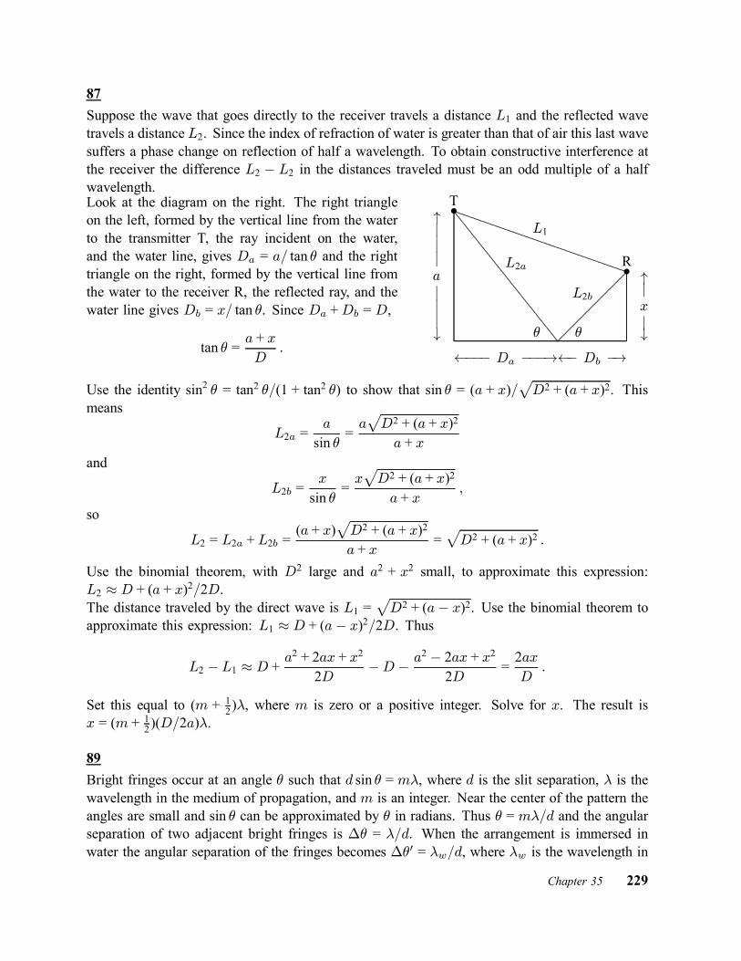
87Suppose the wave that goes directly to the receiver travels a distance L1 and the reflected wavetravels a distance L2. Since the index of refraction of water is greater than that of air this last wavesuffers a phase change on reflection of half a wavelength. To obtain constructive interference atthe receiver the difference L2 ¡ L2 in the distances traveled must be an odd multiple of a halfwavelength.Look at the diagram on the right. The right triangleon the left, formed by the vertical line from the waterto the transmitter T, the ray incident on the water,and the water line, gives Da = a= tan µ and the righttriangle on the right, formed by the vertical line fromthe water to the receiver R, the reflected ray, and thewater line gives Db = x= tan µ. Since Da +Db = D,
tan µ =a + xD
: á¡¡ Da ¡¡¡!á Db ¡!
"jjjajjj#
"jxj#
...............................................................................................................................................................................................................................................................................................................................................................................................
L1
.........................................................................................................................................................................................................................................................................................................................................................................................................................................................................................................................................................................
L2a
L2b
µ µ
²T
R²
Use the identity sin2 µ = tan2 µ=(1 + tan2 µ) to show that sin µ = (a + x)=pD2 + (a + x)2. This
means
L2a =a
sin µ=apD2 + (a + x)2a + x
and
L2b =x
sin µ=xpD2 + (a + x)2
a + x;
so
L2 = L2a + L2b =(a + x)
pD2 + (a + x)2
a + x=pD2 + (a + x)2 :
Use the binomial theorem, with D2 large and a2 + x2 small, to approximate this expression:L2 ¼ D + (a + x)2=2D.The distance traveled by the direct wave is L1 =
pD2 + (a¡ x)2. Use the binomial theorem to
approximate this expression: L1 ¼ D + (a¡ x)2=2D. Thus
L2 ¡ L1 ¼ D + a2 + 2ax + x2
2D¡D ¡ a
2 ¡ 2ax + x22D
=2axD:
Set this equal to (m + 12)¸, where m is zero or a positive integer. Solve for x. The result is
x = (m + 12)(D=2a)¸.
89Bright fringes occur at an angle µ such that d sin µ = m¸, where d is the slit separation, ¸ is thewavelength in the medium of propagation, and m is an integer. Near the center of the pattern theangles are small and sin µ can be approximated by µ in radians. Thus µ = m¸=d and the angularseparation of two adjacent bright fringes is ¢µ = ¸=d. When the arrangement is immersed inwater the angular separation of the fringes becomes ¢µ0 = ¸w=d, where ¸w is the wavelength in
Chapter 35 229

water. Since ¸w = ¸=nw, where nw is the index of refraction of water, ¢µ0 = ¸=nwd = (¢µ)=nw.Since the units of the angles cancel from this equation we may substitute the angles in degreesand obtain ¢µ0 = 0:30±=1:33 = 0:23±.
93(a) For wavelength ¸ dark bands occur where the path difference is an odd multiple of ¸=2. Thatis, where the path difference is (2m + 1)¸=2, where m is an integer. The fourth dark band fromthe central bright fringe is associated with m = 3 and is 7¸=2 = 7(500 nm)=2 = 1750 nm.(b) The angular position µ of the first bright band on either side of the central band is given bysin µ = ¸=d, where d is the slit separation. The distance on the screen is given by ¢y = D tan µ,where D is the distance from the slits to the screen. Because µ is small its sine and tangent arevery nearly equal and ¢y = D sin µ = D¸=d.Dark bands have angular positions that are given by sin µ = (m + 1
2)¸=d and, for the fourth darkband, m = 3 and sin µ4 = (7=2)¸=d. Its distance on the screen from the central fringe is ¢y4 =D tan µ4 = D sin µ4 = 7D¸=2d. This means that D¸=d = 2¢y4=7 = 2(1:68 cm)=7 = 0:48 cm.Note that this is ¢y.
99Minima occur at angles µ for which sin µ = (m + 1
2)¸=d, where ¸ is the wavelength, d is the slitseparation, and m is an integer. For the first minimum, m = 0 and sin µ1 = ¸=2d. For the tenthminimum, m = 9 and sin µ10 = 19¸=2d.The distance on the screen from the central fringe to a minimum is y = D tan µ, where D is thedistance from the slits to the screen. Since the angle is small we may approximate its tangentwith its sine and write y = D sin µ = D(m + 1
2)¸=d. Thus the separation of the first and tenthminima is
¢y =D
d
µ19¸2¡ ¸2
¶=9D¸d
and¸ =
d¢y
9D=(0:150£ 10¡3 m)(18:0£ 10¡3 m)
9(50:0£ 10¡2 m) = 6:00£ 10¡7 m :
103The difference in the path lengths of the two beams is 2x, so their difference in phase whenthey reach the detector is Á = 4¼x=¸, where ¸ is the wavelength. Assume their amplitudesare the same. According to Eq. 35–22 the intensity associated with the addition of two wavesis proportional to the square of the cosine of half their phase difference. Thus the intensity ofthe light observed in the interferometer is proportional to cos2(2¼x=¸). Since the intensity ismaximum when x = 0 (and the arms have equal lengths), the constant of proportionality is themaximum intensity Im and I = Im cos2(2¼x=¸).
230 Chapter 35
Chapter 36
9The condition for a minimum of intensity in a single-slit diffraction pattern is a sin µ = m¸,where a is the slit width, ¸ is the wavelength, and m is an integer. To find the angular positionof the first minimum to one side of the central maximum, set m = 1:
µ1 = sin¡1µ¸
a
¶= sin¡1
µ589£ 10¡9 m1:00£ 10¡3 m
¶= 5:89£ 10¡4 rad :
If D is the distance from the slit to the screen, the distance on the screen from the center of thepattern to the minimum is y1 = D tan µ1 = (3:00m) tan(5:89£ 10¡4 rad) = 1:767£ 10¡3 m.To find the second minimum, set m = 2:
µ2 = sin¡1∙2(589£ 10¡9 m)1:00£ 10¡3 m
¸= 1:178£ 10¡3 rad :
The distance from the pattern center to the minimum is y2 = D tan µ2 = (3:00m) tan(1:178 £10¡3 rad) = 3:534£ 10¡3 m. The separation of the two minima is ¢y = y2 ¡ y1 = 3:534mm¡1:767mm = 1:77mm.
17(a) The intensity for a single-slit diffraction pattern is given by
I = Imsin2 ®®2
;
where ® = (¼a=¸) sin µ, a is the slit width and ¸ is the wavelength. The angle µ is measuredfrom the forward direction. You want I = Im=2, so
sin2 ® =12®2 :
(b) Evaluate sin2 ® and ®2=2 for ® = 1:39 rad and compare the results. To be sure that 1:39 radis closer to the correct value for ® than any other value with three significant digits, you shouldalso try 1:385 rad and 1:395 rad.(c) Since ® = (¼a=¸) sin µ,
µ = sin¡1µ®¸
¼a
¶:
Now ®=¼ = 1:39=¼ = 0:442, so
µ = sin¡1µ0:442¸a
¶:
Chapter 36 231

The angular separation of the two points of half intensity, one on either side of the center of thediffraction pattern, is
¢µ = 2µ = 2 sin¡1µ0:442¸a
¶:
(d) For a=¸ = 1:0,¢µ = 2 sin¡1(0:442=1:0) = 0:916 rad = 52:5± :
(e) For a=¸ = 5:0,¢µ = 2 sin¡1(0:442=5:0) = 0:177 rad = 10:1± :
(f) For a=¸ = 10,¢µ = 2 sin¡1(0:442=10) = 0:0884 rad = 5:06± :
21(a) Use the Rayleigh criteria. To resolve two point sources, the central maximum of the diffractionpattern of one must lie at or beyond the first minimum of the diffraction pattern of the other.This means the angular separation of the sources must be at least µR = 1:22¸=d, where ¸ is thewavelength and d is the diameter of the aperture. For the headlights of this problem,
µR =1:22(550£ 10¡9 m)5:0£ 10¡3 m = 1:3£ 10¡4 rad :
(b) If D is the distance from the headlights to the eye when the headlights are just resolvableand ` is the separation of the headlights, then ` = D tan µR ¼ DµR, where the small angleapproximation tan µR ¼ µR was made. This is valid if µR is measured in radians. ThusD = `=µR = (1:4m)=(1:34£ 10¡4 rad) = 1:0£ 104 m = 10 km.
25(a) Use the Rayleigh criteria: two objects can be resolved if their angular separation at theobserver is greater than µR = 1:22¸=d, where ¸ is the wavelength of the light and d is thediameter of the aperture (the eye or mirror). If D is the distance from the observer to the objects,then the smallest separation ` they can have and still be resolvable is ` = D tan µR ¼ DµR, whereµR is measured in radians. The small angle approximation tan µR ¼ µR was made. Thus
` =1:22D¸d
=1:22(8:0£ 1010 m)(550£ 10¡9 m)
5:0£ 10¡3 m = 1:1£ 107 m = 1:1£ 104 km :
This distance is greater than the diameter of Mars. One part of the planet’s surface cannot beresolved from another part.(b) Now d = 5:1m and
` =1:22(8:0£ 1010 m)(550£ 10¡9 m)
5:1m= 1:1£ 104 m = 11 km :
232 Chapter 36

29(a) The first minimum in the diffraction pattern is at an angular position µ, measured from thecenter of the pattern, such that sin µ = 1:22¸=d, where ¸ is the wavelength and d is the diameterof the antenna. If f is the frequency, then the wavelength is
¸ =c
f=3:00£ 108 m=s220£ 109 Hz = 1:36£ 10¡3 m :
Thusµ = sin¡1
µ1:22¸d
¶= sin¡1
µ1:22(1:36£ 10¡3 m)55:0£ 10¡2 m
¶= 3:02£ 10¡3 rad :
The angular width of the central maximum is twice this, or 6:04£ 10¡3 rad (0:346±).(b) Now ¸ = 1:6 cm and d = 2:3m, so
µ = sin¡1µ1:22(1:6£ 10¡2 m)
2:3m
¶= 8:5£ 10¡3 rad :
The angular width of the central maximum is 1:7£ 10¡2 rad (0:97±).
39(a) The angular positions µ of the bright interference fringes are given by d sin µ = m¸, where d isthe slit separation, ¸ is the wavelength, andm is an integer. The first diffraction minimum occursat the angle µ1 given by a sin µ1 = ¸, where a is the slit width. The diffraction peak extendsfrom ¡µ1 to +µ1, so you want to count the number of values of m for which ¡µ1 < µ < +µ1, orwhat is the same, the number of values of m for which ¡ sin µ1 < sin µ < + sin µ1. This means¡1=a < m=d < 1=a or ¡d=a < m < +d=a. Now d=a = (0:150£ 10¡3 m)=(30:0£ 10¡6 m) =5:00, so the values of m arem = ¡4, ¡3, ¡2, ¡1, 0, +1, +2, +3, and +4. There are nine fringes.(b) The intensity at the screen is given by
I = Im¡cos2 ¯
¢ µsin®®
¶2;
where ® = (¼a=¸) sin µ, ¯ = (¼d=¸) sin µ, and Im is the intensity at the center of the pattern.For the third bright interference fringe, d sin µ = 3¸, so ¯ = 3¼ rad and cos2 ¯ = 1. Similarly,® = 3¼a=d = 3¼=5:00 = 0:600¼ rad andµ
sin®®
¶2=µsin 0:600¼0:600¼
¶2= 0:255 :
The intensity ratio is I=Im = 0:255.
45The ruling separation is d = 1=(400mm¡1) = 2:5£ 10¡3 mm. Diffraction lines occur at angles µsuch that d sin µ = m¸, where ¸ is the wavelength and m is an integer. Notice that for a given
Chapter 36 233
order, the line associated with a long wavelength is produced at a greater angle than the lineassociated with a shorter wavelength. Take ¸ to be the longest wavelength in the visible spectrum(700 nm) and find the greatest integer value of m such that µ is less than 90±. That is, find thegreatest integer value ofm for whichm¸ < d. Since d=¸ = (2:5£10¡6 m)=(700£10¡9 m) = 3:57,that value is m = 3. There are three complete orders on each side of the m = 0 order. Thesecond and third orders overlap.
51(a) Maxima of a diffraction grating pattern occur at angles µ given by d sin µ = m¸, where d is theslit separation, ¸ is the wavelength, and m is an integer. The two lines are adjacent, so their ordernumbers differ by unity. Let m be the order number for the line with sin µ = 0:2 and m+1 be theorder number for the line with sin µ = 0:3. Then 0:2d = m¸ and 0:3d = (m+1)¸. Subtract the firstequation from the second to obtain 0:1d = ¸, or d = ¸=0:1 = (600£10¡9 m)=0:1 = 6:0£10¡6 m.(b) Minima of the single-slit diffraction pattern occur at angles µ given by a sin µ = m¸, where ais the slit width. Since the fourth-order interference maximum is missing, it must fall at one ofthese angles. If a is the smallest slit width for which this order is missing, the angle must be givenby a sin µ = ¸. It is also given by d sin µ = 4¸, so a = d=4 = (6:0£ 10¡6 m)=4 = 1:5£ 10¡6 m.(c) First, set µ = 90± and find the largest value of m for which m¸ < d sin µ. This is the highestorder that is diffracted toward the screen. The condition is the same as m < d=¸ and sinced=¸ = (6:0£ 10¡6 m)=(600£ 10¡9 m) = 10:0, the highest order seen is the m = 9 order.(d) and (e) The fourth and eighth orders are missing so the observable orders are m = 0, 1, 2,3, 5, 6, 7, and 9. The second highest order is the m = 7 order and the third highest order is them = 6 order.
61If a grating just resolves two wavelengths whose average is ¸avg and whose separation is ¢¸,then its resolving power is defined by R = ¸avg=¢¸. The text shows this is Nm, where N isthe number of rulings in the grating and m is the order of the lines. Thus ¸avg=¢¸ = Nm and
N =¸avgm¢¸
=656:3 nm(1)(0:18 nm)
= 3:65£ 103 rulings :
73We want the reflections to obey the Bragg condition 2d sin µ = m¸, where µ is the angle betweenthe incoming rays and the reflecting planes, ¸ is the wavelength, and m is an integer. Solve forµ:
µ = sin¡1∙m¸
2d
¸= sin¡1
∙(0:125£ 10¡9 m)m2(0:252£ 10¡9 m)
¸= sin¡1(0:2480m) :
For m = 1 this gives µ = 14:4±. The crystal should be turned 45± ¡ 14:4± = 30:6± clockwise.For m = 2 it gives µ = 29:7±. The crystal should be turned 45± ¡ 29:7± = 15:3± clockwise.For m = 3 it gives µ = 48:1±. The crystal should be turned 48:1±¡45± = 3:1± counterclockwise.234 Chapter 36

Form = 4 it gives µ = 82:8±. The crystal should be turned 82:8±¡45± = 37:8± counterclockwise.There are no intensity maxima for m > 4 as you can verify by noting that m¸=2d is greater than1 for m greater than 4. For clockwise turns the smaller value is 15:3± and the larger value is30:6±. For counterclockwise turns the smaller value is 3:1± and the larger value is 37:8±.
77Intensity maxima occur at angles µ such that d sin µ = m¸, where d is the separation of adjacentrulings and ¸ is the wavelength. Here the ruling separation is 1=(200mm¡1) = 5:00£10¡3 mm =5:00£ 10¡6 m. Thus
¸ =d sin µm
=(5:00£ 10¡6 m) sin 30:0±
m=2:50£ 10¡6 m
m:
For m = 1, ¸ = 2500 nm; for m = 2, ¸ = 1250 nm; for m ¡ 3, ¸ = 833 nm; for m = 4,¸ = 625 nm; for m = 5, ¸ = 500 nm, and for m = 6, ¸ = 417 nm. Only the last three are inthe visible range, so the longest wavelength in the visible range is 625 nm, the next longest is500 nm, and the third longest is 417 nm.
79Suppose mo is the order of the minimum for orange light, with wavelength ¸o, and mbg isthe order of the minimum for blue-green light, with wavelength ¸bg. Then a sin µ = mo¸o anda sin µ = mbg¸bg. Thus mo¸o = mbg¸bg and mbg=mo = ¸o=¸bg = (600 nm)=(500 nm) = 6=5.The smallest two integers with this ratio are mbg = 6 and mo = 5. The slit width is
a =mo¸osin µ
=5(600£ 10¡9 m
sin(1:00£ 10¡3 rad) = 3:0£ 10¡3 m :
Other values for mo and mbg are possible but these are associated with a wider slit.
81(a) Since the first minimum of the diffraction pattern occurs at the angle µ such that sin µ = ¸=a,where ¸ is the wavelength and a is the slit width, the central maximum extends from µ1 =¡ sin¡1(¸=a) to µ2 = + sin¡1(¸=a). Maxima of the two-slit interference pattern are at angles µsuch that sin µ = m¸=d, where d is the slit separation and m is an integer. We wish to knowthe number of values of m such that sin¡1(m¸=d) lies between ¡ sin¡1(¸=a) and + sin(¸=a) or,what is the same, the number of values of m such that m=d lies between ¡1=a and +1=a. Thegreatest m can be is the greatest integer that is smaller than d=a = (14¹m)=(2:0¹m) = 7. (Them = 7 maximum does not appear since it coincides with a minimum of the diffraction pattern.)There are 13 such values: 0, §1, §2, §3; §4; §5, and §6. Thus 13 interference maxima appearin the central diffraction envelope.(b) The first diffraction envelope extends from µ1 = sin¡1(¸=a) to µ2 = sin¡1(2¸=a). Thus wewish to know the number of values of m such that m=d is greater than 1=a and less than 2=a.Since d = 7:0a, m can be 8, 9, 10, 11, 12, or 13. That is, there are 6 interference maxima in thefirst diffraction envelope.
Chapter 36 235

93If you divide the original slit into N strips and represent the light from each strip, when it reachesthe screen, by a phasor, then at the central maximum in the diffraction pattern you add N phasors,all in the same direction and each with the same amplitude. The intensity there is proportionalto N 2. If you double the slit width, you need 2N phasors if they are each to have the amplitudeof the phasors you used for the narrow slit. The intensity at the central maximum is proportionalto (2N )2 and is, therefore, four times the intensity for the narrow slit. The energy reaching thescreen per unit time, however, is only twice the energy reaching it per unit time when the narrowslit is in place. The energy is simply redistributed. For example, the central peak is now half aswide and the integral of the intensity over the peak is only twice the analogous integral for thenarrow slit.
95(a) Since the resolving power of a grating is given by R = ¸=¢¸ and by Nm, the range ofwavelengths that can just be resolved in order m is ¢¸ = ¸=Nm. Here N is the numberof rulings in the grating and ¸ is the average wavelength. The frequency f is related to thewavelength by f¸ = c, where c is the speed of light. This means f ¢¸ + ¸¢f = 0, so
¢¸ = ¡¸f¢f = ¡¸
2
c¢f ;
where f = c=¸ was used. The negative sign means that an increase in frequency corresponds toa decrease in wavelength. We may interpret ¢f as the range of frequencies that can be resolvedand take it to be positive. Then
¸2
c¢f =
¸
Nm
and¢f =
c
Nm¸:
(b) The difference in travel time for waves traveling along the two extreme rays is ¢t = ¢L=c,where ¢L is the difference in path length. The waves originate at slits that are separated by(N ¡ 1)d, where d is the slit separation and N is the number of slits, so the path difference is¢L = (N ¡ 1)d sin µ and the time difference is
¢t =(N ¡ 1)d sin µ
c:
If N is large, this may be approximated by¢t = (Nd=c) sin µ. The lens does not affect the traveltime.(c) Substitute the expressions you derived for ¢t and ¢f to obtain
¢f ¢t =³ c
Nm¸
´ µNd sin µc
¶=d sin µm¸
= 1 :
The condition d sin µ = m¸ for a diffraction line was used to obtain the last result.
236 Chapter 36

101The dispersion of a grating is given by D = dµ=d¸, where µ is the angular position of a lineassociated with wavelength ¸. The angular position and wavelength are related by ` sin µ = m¸,where ` is the slit separation and m is an integer. Differentiate this with respect to µ to obtain(dµ=d¸) ` cos µ = m or
D =`µ
`¸=
m
` cos µ:
Now m = (`=¸) sin µ, so
D =` sin µ`¸ cos µ
=tan µ¸:
The trigonometric identity tan µ = sin µ= cos µ was used.
Chapter 36 237

Chapter 37
11(a) The rest length L0 (= 130m) of the spaceship and its length L as measured by the timingstation are related by L = L0=° = L0
p1¡ ¯2, where ° = 1=
p1¡ ¯2 and ¯ = v=c. Thus
L = (130m)p1¡ (0:740)2 = 87:4m.
(b) The time interval for the passage of the spaceship is
¢t =L
v=
87:4m(0:740)(2:9979£ 108 m=s) = 3:94£ 10
¡7 s :
19The proper time is not measured by clocks in either frame S or frame S0 since a single clock at restin either frame cannot be present at the origin and at the event. The full Lorentz transformationmust be used:
x0 = °[x¡ vt]t0 = °[t¡ ¯x=c] ;
where ¯ = v=c = 0:950 and ° = 1=p1¡ ¯2 = 1=
p1¡ (0:950)2 = 3:2026. Thus
x0 = (3:2026)£100£ 103 m¡ (0:950)(2:9979£ 108 m=s)(200£ 10¡6 s¤
= 1:38£ 105 m = 138 kmand
t0 = (3:2026)∙200£ 10¡6 s¡ (0:950)(100£ 10
3 m)2:9979£ 108 m=s
¸= ¡3:74£ 10¡4 s = ¡374¹s :
21(a) The Lorentz factor is
° =1p1¡ ¯2 =
1p1¡ (0:600)2 = 1:25 :
(b) In the unprimed frame, the time for the clock to travel from the origin to x = 180m is
t =x
v=
180m(0:600)(2:9979£ 108 m=s) = 1:00£ 10
¡6 s :
The proper time interval between the two events (at the origin and at x = 180m) is measured bythe clock itself. The reading on the clock at the beginning of the interval is zero, so the readingat the end is
t0 =t
°=1:00£ 10¡6 s
1:25= 8:00£ 10¡7 s :
238 Chapter 37

29Use Eq. 37–29 with u0 = 0:40c and v = 0:60c. Then
u =0:40c + 0:60c
1 + (0:40c)(0:60c)=c2= 0:81c :
33Calculate the speed of the micrometeorite relative to the spaceship. Let S0 be the reference framefor which the data is given and attach frame S to the spaceship. Suppose the micrometeorite isgoing in the positive x direction and the spaceship is going in the negative x direction, both asviewed from S0. Then, in Eq. 37–29, u0 = 0:82c and v = 0:82c. Notice that v in the equationis the velocity of S0 relative to S. Thus the velocity of the micrometeorite in the frame of thespaceship is
u =u0 + v
1 + u0v=c2=
0:82c + 0:82c1 + (0:82c)(0:82c)=c2
= 0:9806c :
The time for the micrometeorite to pass the spaceship is
¢t =L
u=
350m(0:9806)(2:9979£ 108 m=s) = 1:19£ 10
¡6 s :
37The spaceship is moving away from Earth, so the frequency received is given by
f = f0
s1¡ ¯1 + ¯
;
where f0 is the frequency in the frame of the spaceship, ¯ = v=c, and v is the speed of thespaceship relative to Earth. See Eq. 37–31. Thus
f = (100MHz)r1¡ 0:90001 + 0:9000
= 22:9MHz :
39The spaceship is moving away from Earth, so the frequency received is given by
f = f0
s1¡ ¯1 + ¯
;
where f0 is the frequency in the frame of the spaceship, ¯ = v=c, and v is the speed of thespaceship relative to Earth. See Eq. 37–31. The frequency f and wavelength ¸ are related byf¸ = c, so if ¸0 is the wavelength of the light as seen on the spaceship and ¸ is the wavelengthdetected on Earth, then
¸ = ¸0
s1 + ¯1¡ ¯ = (450 nm)
r1 + 0:201¡ 0:20 = 550 nm :
Chapter 37 239
This is in the yellow-green portion of the visible spectrum.
43Use the two expressions for the total energy: E = mc2 +K and E = °mc2, where m is the massof an electron, K is the kinetic energy, and ° = 1=
p1¡ ¯2. Thus mc2 +K = °mc2 and
° = 1 +K
mc2= 1 +
(100:000£ 106 eV)(1:602 176 462 J=eV)(9:109 381 88£ 10¡31 kg)(2:997 924 58£ 108 m=s)2 = 196:695 :
Now °2 = 1=(1¡ ¯2), so
¯ =
s1¡ 1
°2=
s1¡ 1
(196:695)2= 0:999 987 :
53The energy equivalent of one tablet is mc2 = (320£10¡6 kg)(2:9979£108 m=s)2 = 2:88£1013 J.This provides the same energy as (2:88 £ 1013 J)=(3:65 £ 107 J=L) = 7:89 £ 105 L of gasoline.The distance the car can go is d = (7:89£ 105 L)(12:75 km=L) = 1:01£ 107 km.
71The energy of the electron is given by E = mc2=
p1¡ (v=c)2, which yields
v =
s1¡∙mc2
E
¸2c =
s1¡∙(9:11£ 10¡31 kg)(2:9979£ 108 m=s)2(1533MeV)(1:602£ 10¡13 J=MeV)
¸2= 0:99999994c ¼ c
for the speed v of the electron. In the rest frame of Earth the trip took time t = 26 y. A clocktraveling with the electron records the proper time of the trip, so the trip in the rest frame of theelectron took time t0 = t=°. Now
° =E
mc2=1533MeV)(1:602£ 10¡13 J=MeV)(9:11£ 10¡31 kg)(2:9979£ 108 m=s) = 3:0£ 10
3
and t0 = (26 y)=(3:0£ 103) = 8:7£ 10¡3 y. The distance traveled is 8:7£ 10¡3 ly.
73Start with (pc)2 = K2 +2Kmc2, where p is the momentum of the particle, K is its kinetic energy,and m is its mass. For an electron mc2 = 0:511MeV, so
pc =pK2 + 2Kmc2 =
p(2:00MeV)2 + 2(2:00MeV)(0:511MeV) = 2:46MeV :
Thus p = 2:46MeV=c.
75The work required is the increased in the energy of the proton. The energy is given by E =mc2=[1¡ (v=c)2]. Let v1 be the initial speed and v2 be the final speed. Then the work is
W =mc2p
1¡ (v2=c)2¡ mc2p
1¡ (v=c)2 =938MeVp1¡ (0:9860)2 ¡
938MeVp1¡ (0:9850)2 = 189MeV ;
240 Chapter 37
where mc2 = 938MeV was used.
77(a) Let v be the speed of either satellite, relative to Earth. According to the Galilean velocitytransformation equation the relative speed is vrel = 2v = 2(2:7£ 104 km=h = 5:4£ 104 km=h.(b) The correct relativistic transformation equation is
vrel =2v
1 + v2
c2
:
The fractional error isfract err =
2v ¡ vrel2v
= 1¡ 1
1 + v2
c2
:
The speed of light is 1:08£ 109 km=h, so
fract err =1
1 + (2:7£ 104 km=h)2
(1:08£ 109 km=h)2= 6:3£ 10¡10 :
Chapter 37 241

Chapter 38
7(a) Let R be the rate of photon emission (number of photons emitted per unit time) and let E bethe energy of a single photon. Then the power output of a lamp is given by P = RE if all thepower goes into photon production. Now E = hf = hc=¸, where h is the Planck constant, f isthe frequency of the light emitted, and ¸ is the wavelength. Thus P = Rhc=¸ and R = ¸P=hc.The lamp emitting light with the longer wavelength (the 700-nm lamp) emits more photons perunit time. The energy of each photon is less so it must emit photons at a greater rate.(b) Let R be the rate of photon production for the 700 nm lamp Then
R =¸P
hc=
(700£ 10¡9 m)(400 J=s)(6:626£ 10¡34 J ¢ s)(2:9979£ 108 m=s) = 1:41£ 10
21 photon=s :
17The energy of an incident photon is E = hf = hc=¸, where h is the Planck constant, f is thefrequency of the electromagnetic radiation, and ¸ is its wavelength. The kinetic energy of themost energetic electron emitted is Km = E ¡© = (hc=¸)¡©, where © is the work function forsodium. The stopping potential V0 is related to the maximum kinetic energy by eV0 = Km, soeV0 = (hc=¸)¡ © and
¸ =hc
eV0 + ©=(6:626£ 19¡34 J ¢ s)(2:9979£ 108 m=s)(5:0 eV + 2:2 eV)(1:602£ 10¡19 J=eV) = 1:7£ 10
¡7 m :
Here eV0 = 5:0 eV was used.
21(a) The kinetic energyKm of the fastest electron emitted is given byKm = hf¡© = (hc=¸)¡©,where © is the work function of aluminum, f is the frequency of the incident radiation, and ¸ isits wavelength. The relationship f = c=¸ was used to obtain the second form. Thus
Km =(6:626£ 10¡34 J ¢ s)(2:9979£ 108 m=s)(200£ 10¡9 m)(1:602£ 10¡19 J=eV) ¡ 4:20 eV = 2:00 eV :
(b) The slowest electron just breaks free of the surface and so has zero kinetic energy.(c) The stopping potential V0 is given by Km = eV0, so V0 = Km=e = (2:00 eV)=e = 2:00V.(d) The value of the cutoff wavelength is such that Km = 0. Thus hc=¸ = © or
¸ =hc
©=(6:626£ 10¡34 J ¢ s)(2:9979£ 108 m=s)
(4:2 eV)(1:602£ 10¡19 J=eV) = 2:95£ 10¡7 m :
242 Chapter 38

If the wavelength is longer, the photon energy is less and a photon does not have sufficient energyto knock even the most energetic electron out of the aluminum sample.
29(a) When a photon scatters from an electron initially at rest, the change in wavelength is givenby ¢¸ = (h=mc)(1 ¡ cosÁ), where m is the mass of an electron and Á is the scattering angle.Now h=mc = 2:43£ 10¡12 m = 2:43 pm, so ¢¸ = (2:43 pm)(1¡ cos 30±) = 0:326 pm. The finalwavelength is ¸0 = ¸ +¢¸ = 2:4 pm + 0:326 pm = 2:73 pm.(b) Now ¢¸ = (2:43 pm)(1¡ cos 120±) = 3:645 pm and ¸0 = 2:4 pm + 3:645 pm = 6:05 pm.
43Since the kinetic energy K and momentum p are related by K = p2=2m, the momentum of theelectron is p =
p2mK and the wavelength of its matter wave is ¸ = h=p = h=
p2mK. Replace
K with eV , where V is the accelerating potential and e is the fundamental charge, to obtain
¸ =hp2meV
=6:626£ 10¡34 J ¢ sp
2(9:109£ 10¡31 kg)(1:602£ 10¡19 C)(25:0£ 103 V)= 7:75£ 10¡12 m = 7:75 pm :
47(a) The kinetic energy acquired is K = qV , where q is the charge on an ion and V is theaccelerating potential. Thus K = (1:602 £ 10¡19 C)(300V) = 4:80 £ 10¡17 J. The mass ofa single sodium atom is, from Appendix F, m = (22:9898 g=mol)=(6:02 £ 1023 atom=mol) =3:819£ 10¡23 g = 3:819£ 10¡26 kg. Thus the momentum of an ion is
p =p2mK =
p2(3:819£ 10¡26 kg)(4:80£ 10¡17 J) = 1:91£ 10¡21 kg ¢m=s :
(b) The de Broglie wavelength is
¸ =h
p=
6:63£ 10¡34 J ¢ s1:91£ 10¡21 kg ¢m=s = 3:47£ 10
¡13 m :
49Since the kinetic energy K and momentum p are related by K = p2=2m, the momentum of theelectron is p =
p2mK and the wavelength of its matter wave is ¸ = h=p = h=
p2mK. Thus
K =12m
µh
¸
¶2=
12(9:11£ 10¡31 kg)
µ6:626£ 10¡34 J ¢ s)590£ 10¡9 m)
¶2= 6:92£ 10¡25 J = 4:33£ 10¡6 eV :
59The angular wave number k is related to the wavelength ¸ by k = 2¼=¸ and the wavelength isrelated to the particle momentum p by ¸ = h=p, so k = 2¼p=h. Now the kinetic energy K and
Chapter 38 243
the momentum are related byK = p2=2m, wherem is the mass of the particle. Thus p =p2mK
and
k =2¼p2mKh
:
61For U = U0, Schrodinger’s equation becomes
d2Ã
dx2+8¼2mh2
[E ¡ U0]Ã = 0 :
Substitute à = Ã0eikx. The second derivative is d2Ã=dx2 = ¡k2Ã0eikx = ¡k2Ã. The result is
¡k2Ã + 8¼2m
h2[E ¡ U0]Ã = 0 :
Solve for k and obtain
k =r8¼2mh2
[E ¡ U0] = 2¼h
p2m [E ¡ U0] :
67(a) If m is the mass of the particle and E is its energy, then the transmission coefficient for abarrier of height U and width L is given by
T = e¡2kL ;
where
k =r8¼2m(U ¡ E)
h2:
If the change ¢U in U is small (as it is), the change in the transmission coefficient is given by
¢T =dT
dU¢U = ¡2LT dk
dU¢U :
Nowdk
dU=
12pU ¡E
r8¼2mh2
=1
2(U ¡E)
r8¼2m(U ¡ E)
h2=
k
2(U ¡ E) :
Thus¢T = ¡LTk ¢U
U ¡ E :For the data of Sample Problem 38–7, 2kL = 10:0, so kL = 5:0 and
¢T
T= ¡kL ¢U
U ¡E = ¡(5:0) (0:010)(6:8 eV)6:8 eV¡ 5:1 eV = ¡0:20 :
There is a 20% decrease in the transmission coefficient.
244 Chapter 38

(b) The change in the transmission coefficient is given by
¢T =dT
dL¢L = ¡2ke¡2kL¢L = ¡2kT ¢L
and¢T
T= ¡2k¢L = ¡2(6:67£ 109 m¡1)(0:010)(750£ 10¡12 m) = ¡0:10 :
There is a 10% decrease in the transmission coefficient.(c) The change in the transmission coefficient is given by
¢T =dT
dE¢E = ¡2Le¡2kL dk
dE¢E = ¡2LT dk
dE¢E :
Now dk=dE = ¡dk=dU = ¡k=2(U ¡E), so¢T
T= kL
¢E
U ¡ E = (5:0)(0:010)(5:1 eV)6:8 eV¡ 5:1 eV = 0:15 :
There is a 15% increase in the transmission coefficient.
79The uncertainty in the momentum is ¢p = m¢v = (0:50 kg)(1:0m=s) = 0:50 kg ¢m=s, where ¢vis the uncertainty in the velocity. Solve the uncertainty relationship ¢x¢p h for the minimumuncertainty in the coordinate x: ¢x =h=¢p = (0:60 J ¢ s)=2¼(0:50 kg ¢m=s) = 0:19m.
Chapter 38 245
Chapter 39
13
The probability that the electron is found in any interval is given by P =R
jÃj2 dx, where theintegral is over the interval. If the interval width ¢x is small, the probability can be approximatedby P = jÃj2 ¢x, where the wave function is evaluated for the center of the interval, say. For anelectron trapped in an infinite well of width L, the ground state probability density is
jÃj2 =2L
sin2³¼x
L
´;
so
P =µ
2 ¢x
L
¶sin2
³¼x
L
´:
(a) Take L = 100pm, x = 25 pm, and ¢x = 5:0pm. Then
P =·
2(5:0 pm)100 pm
¸sin2
·¼(25 pm)100 pm
¸= 0:050 :
(b) Take L = 100pm, x = 50pm, and ¢x = 5:0pm. Then
P =·
2(5:0 pm)100 pm
¸sin2
·¼(50 pm)100 pm
¸= 0:10 :
(c) Take L = 100pm, x = 90 pm, and ¢x = 5:0pm. Then
P =·
2(5:0 pm)100 pm
¸sin2
·¼(90 pm)100pm
¸= 0:0095 :
25The energy levels are given by
Enx ny =h2
8m
"n2
x
L2x
+n2
y
L2y
#=
h2
8mL2
"n2
x +n2
y
4
#;
where the substitutions Lx = L and Ly = 2L were made. In units of h2=8mL2, the energylevels are given by n2
x + n2y=4. The lowest five levels are E1;1 = 1:25, E1;2 = 2:00, E1;3 = 3:25,
E2;1 = 4:25, and E2;2 = E1;4 = 5:00. A little thought should convince you that there are no otherpossible values for the energy less than 5.The frequency of the light emitted or absorbed when the electron goes from an initial state i to afinal state f is f = (Ef ¡ Ei)=h and in units of h=8mL2 is simply the difference in the values ofn2
x + n2y=4 for the two states. The possible frequencies are 0:75 (1,2¡!1,1), 2:00 (1,3 ¡! 1,1),
3:00 (2,1 ¡! 1,1), 3:75 (2,2¡!1,1), 1:25 (1,3¡!1,2), 2:25 (2,1 ¡! 1,2), 3:00 (2,2 ¡! 1,2),1:00 (2,1 ¡!1,3), 1:75 (2,2 ¡!1,3), 0:75 (2,2¡!2,1), all in units of h=8mL2 .
246 Chapter 39

There are 8 different frequencies in all. In units of h=8mL2 the lowest is 0:75, the second lowestis 1:00, and the third lowest is 1:25. The highest is 3:75, the second highest is 3:00, and thethird highest is 2:25.
33
If kinetic energy is not conserved some of the neutron’s initial kinetic energy is used to excite thehydrogen atom. The least energy that the hydrogen atom can accept is the difference between thefirst excited state (n = 2) and the ground state (n = 1). Since the energy of a state with principalquantum number n is ¡(13:6 eV)=n2, the smallest excitation energy is 13:6 eV¡(13:6eV)=(2)2 =10:2 eV. The neutron does not have sufficient kinetic energy to excite the hydrogen atom, so thehydrogen atom is left in its ground state and all the initial kinetic energy of the neutron ends upas the final kinetic energies of the neutron and atom. The collision must be elastic.
37The energy E of the photon emitted when a hydrogen atom jumps from a state with principalquantum number u to a state with principal quantum number ` is given by
E = A
µ1`2 ¡ 1
u2
¶;
where A = 13:6eV. The frequency f of the electromagnetic wave is given by f = E=h and thewavelength is given by ¸ = c=f. Thus
1¸
=f
c=
E
hc=
A
hc
µ1`2 ¡ 1
u2
¶:
The shortest wavelength occurs at the series limit, for which u = 1. For the Balmer series,` = 2 and the shortest wavelength is ¸B = 4hc=A. For the Lyman series, ` = 1 and the shortestwavelength is ¸L = hc=A. The ratio is ¸B=¸L = 4.
43The proposed wave function is
à =1p
¼a3=2e¡r=a ;
where a is the Bohr radius. Substitute this into the right side of Schrodinger’s equation and showthat the result is zero. The derivative is
dÃ
dr= ¡ 1p
¼a5=2 e¡r=a ;
so
r2 dÃ
dr= ¡ r2
p¼a5=2
e¡r=a
and1r2
d
dr
µr2 dÃ
dr
¶=
1p¼a5=2
·¡2
r+
1a
¸e¡r=a =
1a
·¡2
r+
1a
¸Ã :
Chapter 39 247

Now the energy of the ground state is given by E = ¡me4=8²20h
2 and the Bohr radius is givenby a = h2²0=¼me2, so E = ¡e2=8¼²0a. The potential energy is given by U = ¡e2=4¼²0r, so
8¼2m
h2[E ¡ U ] Ã =
8¼2m
h2
·¡ e2
8¼²0a+
e2
4¼²0r
¸Ã =
8¼2m
h2
e2
8¼²0
·¡1
a+
2r
¸Ã
=¼me2
h2²0
·¡1
a+
2r
¸Ã =
1a
·¡1
a+
2r
¸Ã :
The two terms in Schrodinger’s equation obviously cancel and the proposed function à satisfiesthat equation.
47
The radial probability function for the ground state of hydrogen is P (r) = (4r2=a3)e¡2r=a, wherea is the Bohr radius. (See Eq. 39–44.) You want to evaluate the integral
R 10 P (r) dr. Eq. 15 in
the integral table of Appendix E is an integral of this form. Set n = 2 and replace a in the givenformula with 2=a and x with r. Then
Z 1
0P (r) dr =
4a3
Z 1
0r2e¡2r=a dr =
4a3
2(2=a)3 = 1 :
49(a) Ã210 is real. Simply square it to obtain the probability density:
jÃ210j2 =r2
32¼a5 e¡r=a cos2 µ :
(b) Each of the other functions is multiplied by its complex conjugate, obtained by replacing iwith ¡i in the function. Since eiÁe¡iÁ = e0 = 1, the result is the square of the function withoutthe exponential factor:
jÃ21+1 j2 =r2
64¼a5 e¡r=a sin2 µ
jÃ21¡1j2 =r2
64¼a5 e¡r=a sin2 µ :
The last two functions lead to the same probability density.(c) For m` = 0 the radial probability density decreases strongly with distance from the nucleus,is greatest along the z axis, and for a given distance from the nucleus decreases in proportion tocos2 µ for points away from the z axis. This is consistent with the dot plot of Fig. 39–24 (a).For m` = §1 the radial probability density decreases strongly with distance from the nucleus, isgreatest in the x; y plane, and for a given distance from the nucleus decreases in proportion tosin2 µ for points away from that plane. Thus it is consistent with the dot plot of Fig. 39-24(b).(d) The total probability density for the three states is the sum:
jÃ210j2 + jÃ21+1j2 + jÃ21¡1j2 =r2
32¼a5e¡r=a
·cos2 µ +
12
sin2 µ +12
sin2 µ
¸
=r2
32¼a5 e¡r=a :
248 Chapter 39

The trigonometric identity cos2 µ + sin2 µ = 1 was used. The total probability density does notdepend on µ or Á. It is spherically symmetric.
57
The wave function is à =p
Ce¡kx. Substitute this function into Schrodinger’s equation,
¡ h2
8¼2m
d2Ã
dx2 + U0Ã = EÃ :
Since d2Ã=dx2 =p
Ck2e¡kx = k2Ã, the result is
h2k2
8¼2mà + U0à = Eà :
The solution for k is
k =
r8¼2m
h2 (U0 ¡ E) :
Thus the function given for à is a solution to Schrodinger’s equation provided k has the valuecalculated from the expression given above.
Chapter 39 249