89723sl.pdf Reelmaster 450-D (Rev A) 1998
306
Part No. 89723SL, Rev. A Service Manual Reelmaster R 450–D Preface The purpose of this publication is to provide the service technician with information for troubleshooting, testing, and repair of major systems and components on the Reelmaster 450–D. REFER TO THE TRACTION UNIT AND CUTTING UNIT OPERATOR’S MANUALS FOR OPERATING, MAINTENANCE AND ADJUSTMENT INSTRUC- TIONS. Space is provided in Chapter 2 of this book to insert the Operator’s Manuals and Parts Catalogs for your machine. Replacement Operator’s Manuals are available by sending complete Model and Serial Num- ber to: The Toro Company 8111 Lyndale Avenue South Minneapolis, MN 55420 The Toro Company reserves the right to change product specifications or this publication without notice. This safety symbol means DANGER, WARN- ING, or CAUTION, PERSONAL SAFETY INSTRUCTION. When you see this symbol, carefully read the instructions that follow. Failure to obey the instructions may result in personal injury. NOTE: A NOTE will give general information about the correct operation, maintenance, service, testing or re- pair of the machine. IMPORTANT: The IMPORTANT notice will give im- portant instructions which must be followed to pre- vent damage to systems or components on the machine. E The Toro Company – 1991, 1998
-
Upload
negimachi-negimachi -
Category
Documents
-
view
222 -
download
2
description
89723sl.pdf Reelmaster 450-D (Rev A) 1998 サービスマニュアル
Transcript of 89723sl.pdf Reelmaster 450-D (Rev A) 1998
Part No. 89723SL, Rev. A
Service Manual
Reelmaster � 450–D
Preface
The purpose of this publication is to provide the servicetechnician with information for troubleshooting, testing,and repair of major systems and components on theReelmaster 450–D.
REFER TO THE TRACTION UNIT AND CUTTINGUNIT OPERATOR’S MANUALS FOR OPERATING,MAINTENANCE AND ADJUSTMENT INSTRUC-TIONS. Space is provided in Chapter 2 of this book toinsert the Operator’s Manuals and Parts Catalogs foryour machine. Replacement Operator’s Manuals areavailable by sending complete Model and Serial Num-ber to:
The Toro Company8111 Lyndale Avenue SouthMinneapolis, MN 55420
The Toro Company reserves the right to change productspecifications or this publication without notice.
This safety symbol means DANGER, WARN-ING, or CAUTION, PERSONAL SAFETYINSTRUCTION. When you see this symbol,carefully read the instructions that follow.Failure to obey the instructions may result inpersonal injury.
NOTE: A NOTE will give general information about thecorrect operation, maintenance, service, testing or re-pair of the machine.
IMPORTANT: The IMPORTANT notice will give im-portant instructions which must be followed to pre-vent damage to systems or components on themachine.
� The Toro Company – 1991, 1998

Reelmaster 4500–D
Rev. AReelmaster 450–D
Table Of Contents
Chapter 1 – Safety
Safety Instructions 1 – 1. . . . . . . . . . . . . . . . . . . . . . . . . .
Chapter 2 – Product Records and Manuals
Product Records 2 – 1. . . . . . . . . . . . . . . . . . . . . . . . . . . Equivalents and Conversions 2 – 2. . . . . . . . . . . . . . . . Torque Specifications 2 – 3. . . . . . . . . . . . . . . . . . . . . . . Equipment Operational and Service Historical Report Record 2 – 5. . . . . . . . . . . .
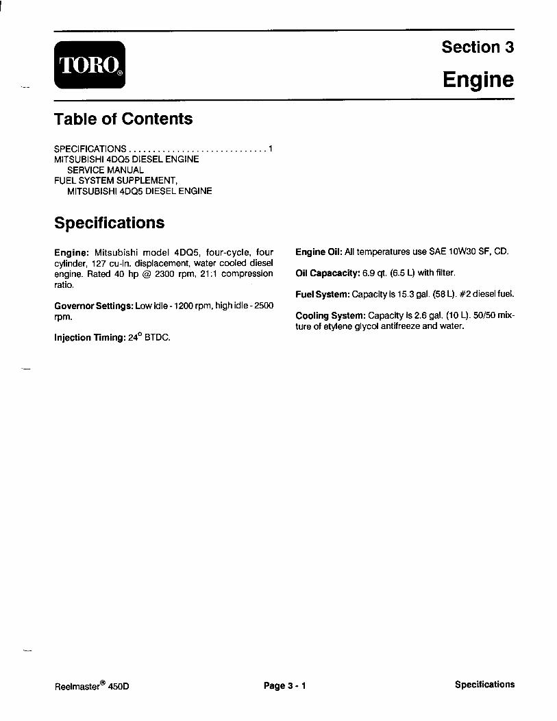
Chapter 3 – Engine
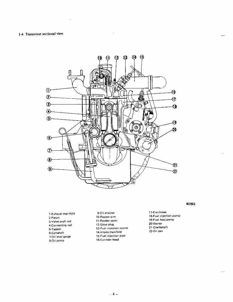
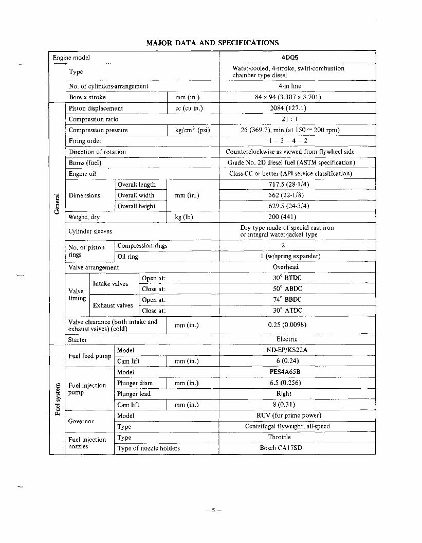
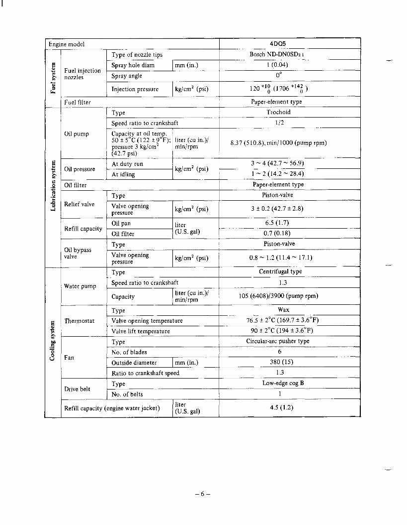
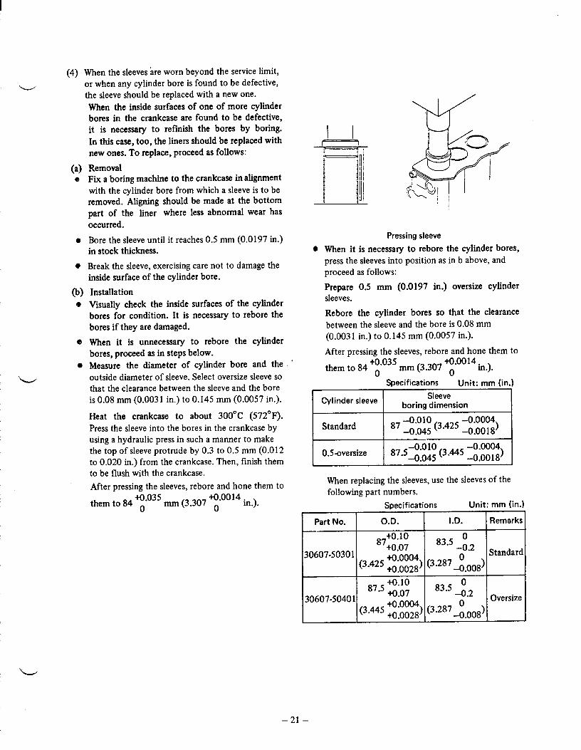
Specifications 3 – 1. . . . . . . . . . . . . . . . . . . . . . . . . . . . . . Service Manual, Mitsubishi 4DQ5 Diesel EngineService Manual Supplement, Fuel System
Chapter 4 – Hydraulic System
Specifications 4 – 1. . . . . . . . . . . . . . . . . . . . . . . . . . . . . . Hydraulic Hose and Fitting Information 4 – 2. . . . . . . . Schematics 4 – 4. . . . . . . . . . . . . . . . . . . . . . . . . . . . . . . . Troubleshooting 4 – 16. . . . . . . . . . . . . . . . . . . . . . . . . . . Testing 4 – 22. . . . . . . . . . . . . . . . . . . . . . . . . . . . . . . . . . . Eaton Char–Lynn Steering Control Repair InformationCessna Service InstructionsVickers Gear Pump Service ManualAuburn Gear Power Wheel Planetary Gear Drive Service Manual
Chapter 5 – Electrical System
Specifications 5 – 1. . . . . . . . . . . . . . . . . . . . . . . . . . . . . . Electrical Schematics (S/N 60001 – 80100) 5 – 2. . . . Electrical Schematic (S/N 80101 – 09999) 5 – 12. . . . Electrical Schematic (S/N 10001 & UP) 5 – 13. . . . . .
Chapter 6 – Cutting Units
Specifications 6 – 2. . . . . . . . . . . . . . . . . . . . . . . . . . . . . . Special Tools 6 – 3. . . . . . . . . . . . . . . . . . . . . . . . . . . . . . Adjustments 6 – 5. . . . . . . . . . . . . . . . . . . . . . . . . . . . . . . Repairs 6 – 9. . . . . . . . . . . . . . . . . . . . . . . . . . . . . . . . . . .

Reelmaster 4500–D


Rev. AReelmaster 450–D Page 2 – 1 Product Records and Manuals
Chapter 2
Product Records and Manuals
Table of Contents
PRODUCT RECORDS 1. . . . . . . . . . . . . . . . . . . . . . . . . EQUIVALENTS AND CONVERSIONS 2. . . . . . . . . . .
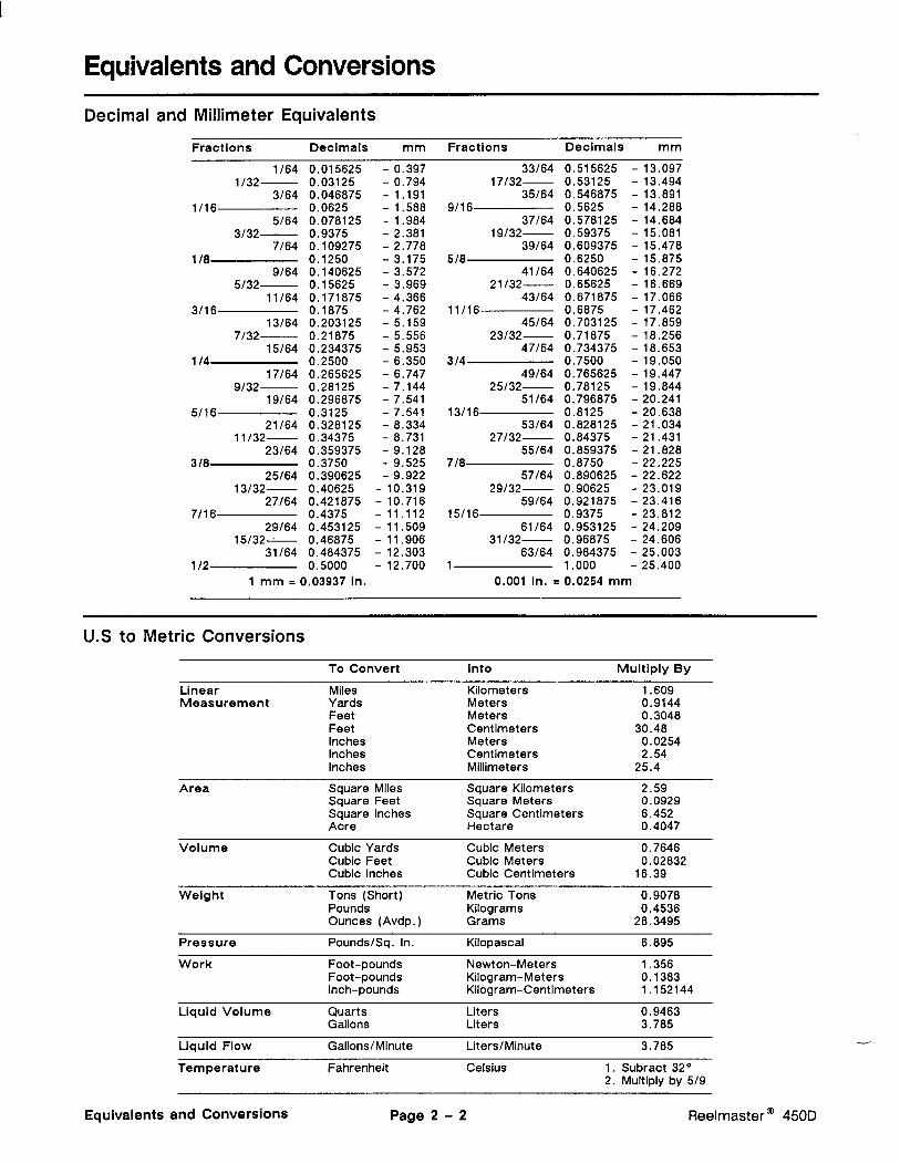
Decimal and Millimeter Equivalents 2. . . . . . . . . . . . U.S. to Metric Conversions 2. . . . . . . . . . . . . . . . . . .
TORQUE SPECIFICATIONS 3. . . . . . . . . . . . . . . . . . . Capscrew Markings and Torque Values – U.S. 3. . Capscrew Markings and Torque Values – Metric 3.
OPERATION AND SERVICE HISTORY REPORT 5.
Product Records
Record information about your Reelmaster 450–D onthe OPERATION AND SERVICE HISTORY REPORTform. Use this information when referring to your ma-chine.
Insert Operator’s Manuals and Parts Catalogs for yourReelmaster 450–D at the end of this section.


Rev. A Reelmaster 450–DPage 2 – 4Product Records and Manuals
This page is blank.

Rev. AReelmaster 450–D Page 2 – 5 Product Records and Manuals
EQUIPMENT OPERATION AND SERVICE HISTORY REPORTfor
REELMASTER� 450–D and 4500–D
TORO Model and Serial Number: ______________–______________
Engine Numbers: _____________________________
Transmission Numbers: _____________________________
Drive Axle(s) Numbers: _____________________________
Date Purchased: _____________________________ Warranty Expires____________
Purchased From: _____________________________
_____________________________
_____________________________
Contacts: Parts _____________________________ Phone____________________
Service _____________________________ Phone____________________
Sales _____________________________ Phone____________________

Rev. A Reelmaster 450–DPage 2 – 6Product Records and Manuals
REELMASTER 450–D and 4500–D Maintenance Schedule
Minimum Recommended Maintenance Intervals
Lubricate Reel Control Valve Grease Fitting
Lubricate Reel Speed Control Valve with Oil
Lubricate all Grease Fittings
Check Battery Condition and Connections
� Change Engine Oil and Filter
Drain Water from Hydraulic Tank
� Check Fan and Alternator Belt
Inspect Cooling System Hoses
Service Air Cleaner Filter Element
Inspect Cutting Unit Reel Drive Belts
� Torque Wheel Lug Nuts
Replace Fuel Filter
Inspect Fuel Lines and Connections
� Torque Cylinder Head and Adjust Valves
� Check Engine RPM (idle and full throttle)
Drain and Clean Fuel Tank
� Replace Hydraulic Oil Filter
Replace Hydraulic Tank Breather
� Change Front Planetary Gear Lube
Pack Rear Axle Bearings (2wd)
Check Rear Wheel Toe–In
� Initial break in at 10 hours
� Initial break in at 50 hours
Replace all Moving Hoses
Replace Safety Switches
Cooling System – Flush / Replace Fluid
Change Hydraulic Oil
��� � � � ������
Every50hrs
Every100hrs
Every200hrs
Every800hrs
��� � � � � ����� � �����
Annual Recommendations:Items listed are recommended every 1500hours or 2 years, whichever occurs first.
Every400hrs
A LevelService
B LevelService
C LevelService
D LevelService
E LevelService

Rev. AReelmaster 450–D Page 2 – 7 Product Records and Manuals
REELMASTER 450–D and 4500–D Daily Maintenance Check List
�� #/ �� %*�%�%��� ��+'# ��*� *� ) '��� �&( (&+* %� +)������" '(&'�( )��* &% &� �'�(�*&(�) ��%+�# �&( �#+ � )'�� � ��* &%)
MaintenanceDaily Maintenance Check For Week Of_________________
Check Item � MON TUES WED THURS FRI SAT SUN
� Safety Interlock Operation
� Parking Brake Operation
� Engine Oil Level
� Fuel Level
� Cooling System Fluid Level
Drain Water/Fuel Separator
� Dust Cup and Baffle (Air Filter)
� Radiator & Screen for Debris1
Clean Traction Pedal Lockout
� Unusual Engine Noises2
� Unusual Operating Noises
� Hydraulic System Oil Level
� Hydraulic Hoses for Damage
� Fluid Leaks
� Tire Pressure
� Instrument Operation
� Warning Lamps Operation
� Reel–to–Bedknife Adjustment
� Height–of–Cut Adjustment
Lubricate All Grease Fittings3
Touch–up Damaged Paint
�� �)� &%#/ #&- '(�))+(� �&$'(�))�� � ( �&( ���( ) (�$&,�#� �� �� � � �������� ����" �#&- '#+� �%� %!��*&( %&00#�)� � ��(� )*�(* %�� �.��)) )$&"� &( (&+�� (+%% %� ) %&*���� �$$�� �*�#/ ��*�( �,�(/ -�)� %�� (���(�#�)) &� *�� %*�(,�# # )*���
������ ��� ���� �� ������ �%)'��* &% '�(�&($�� �/�����������������������������
�*�$ ��*� �%�&($�* &%
�
�
�
�
�

Rev. A Reelmaster 450–DPage 2 – 8Product Records and Manuals


This page is blank.

Reelmaster 450–D Page 6 – 1 Cutting UnitsRev. A
Chapter 6
Cutting Units
Table of Contents
SPECIFICATIONS 2. . . . . . . . . . . . . . . . . . . . . . . . . . . . SPECIAL TOOLS 3. . . . . . . . . . . . . . . . . . . . . . . . . . . . . ADJUSTMENTS 5. . . . . . . . . . . . . . . . . . . . . . . . . . . . . .
Adjusting Reel to Bedknife Contact 5. . . . . . . . . . . . Height of Cut Adjustment (Floating Cutting Unit) 6. Quick Method for Changing Height of Cut After Initial Set Up of a Floating Cutting Unit 8. . . Height of Cut Adjustment (Fixed Cutting Unit) 8. . . Adjusting Skids and Front Roller (Fixed Head Cutting Unit) 8. . . . . . . . . . . . . . . . . . . .
REPAIRS 9. . . . . . . . . . . . . . . . . . . . . . . . . . . . . . . . . . . . Backlapping 9. . . . . . . . . . . . . . . . . . . . . . . . . . . . . . . . Hydraulic Motor Installation 10. . . . . . . . . . . . . . . . . . Servicing the Bedknife/Bedbar Assembly 12. . . . . . Servicing the Reel Assembly 13. . . . . . . . . . . . . . . . . Roller Removal and Installation 16. . . . . . . . . . . . . . .

Reelmaster 450–DPage 6 – 2Cutting Units Rev. A
Specifications
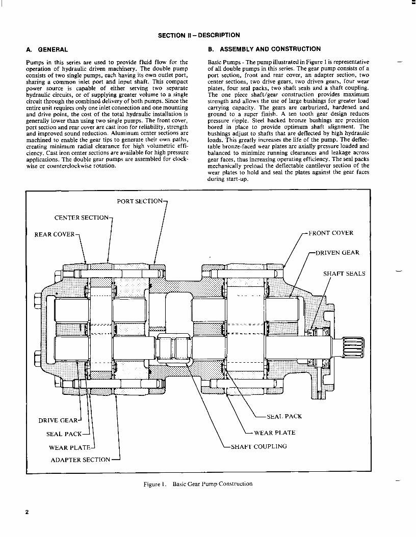
Figure 1
1. Drive housing cover 6. Reel to bedknife2. Drive housing adjusting assembly3. Reel motor fasteners, 7. Guard drive plate shield and 8. Cone nut shipping cover 9. Reel assembly4. Grass deflector 10. Front roller (optional)5. Rear roller adjusting 11. Top covers assembly
Construction: Welded steel frame and reel with heavyduty, self–aligning ball bearings. Heavy duty steel rearroller with tapered roller bearings. Rear roller and bed-bar are isolated and mounted in rubber bushings forquiet, vibration–free operation. Adjustable deflectorshields are standard. Stainless steel components areused at key points for added durability.
Reel Configuration: The 5, 7 and 11 blade heavy dutywelded reels all have 8 in. (20.3 cm) diameters and are29–3/4 in. (75.5 cm) wide.
Bedknife/Bedbar Assembly: A replaceable, singleedged, alloy steel bedbar is induction hardened. It’s fas-tened with steel screws to a precision ground surface onthe high strength, fabricated steel bedbar. The stress–relieved machined bedbar is mounted with four (4)vibration isolation bushings.
Bedknife to Reel Adjustment: Two lockable leadscrew adjusters at each side of the frame adjust the reelto bedknife contact.
Rear Roller: 3–1/2 in. (89 mm) diameter steel roller hasgreaseable tapered roller bearings. A double lip oil sealand wear sleeve isolates grit and moisture from thebearings.
Height–of–Cut: 5 Blade – 1 to 3 in. (25 to 76 mm). 7Blade – 1/2 to 1–3/4 in. (9.5 to 45 mm). 1 1 Blade – 3/8to 3/4 in. (9.5 to 19 mm).
Height–of–Cut Adjustment: Quick adjustment andpositive locking is provided by locking type cone nuts.Gauge marks of 1/4 in. (6.3 mm) are provided as a refer-ence for easy changes of height–of–cut.
Clip (variable to match cutting conditions):
5 Blade Cutting Unit: .176 in. per mph(.352 in. at 2 mph – 1.32 in. at 7.5 mph)
7 Blade Cutting Unit: .1 26 in. per mph(.252 in. at 2 mph – .945 in. at 7.5 mph)
11 Blade Cutting Unit: .080 in. per mph(.16 in. at 2 mph – .600 in. at 7.5 mph)
Lubrication: Easily accessible grease fittings for bear-ings and all major pivot points.
Drive: The reel drive motor turns a maintenance–freecog belt which drives the reel. Drive pulley and cog beltare encased in a drive housing for safety and protectionfrom contamination.
Grass Deflector Shields: Fully Adjustable.

Reelmaster 450–D Page 6 – 3 Cutting UnitsRev. A
Special Tools
Order special tools from the TORO SPECIAL TOOLSAND APPLICATIONS GUIDE (COMMERCIAL PROD-UCTS). Some tools may be listed in the Reelmaster
4500–D Parts Catalog. Some tools may also be avail-able from a local supplier.
Gauge Bar Assembly
Use gauge bar to set final height of cut (floating cuttingunit with front roller only).
Figure 2
Handle Assembly
For applying lapping compound to cutting units whilekeep hands a safe distance from the rotating reel.
Figure 3

Reelmaster 450–DPage 6 – 4Cutting Units Rev. A
Bedknife Screw Tool
Fits Toro bedknife attaching screws. Use with torquewrench to secure bedknife to bedbar. With clean bedbarthreads and new screws, tighten to a torque of 250 in–lb.
NOTE: Remove all rust, scale and corrosion from bed-bar surface before installing bedknife.
DO NOT use and air impact wrench with this tool.
Figure 4

CAUTION
CAUTION
CAUTION
Reelmaster 450–D Page 6 – 5 Cutting UnitsRev. A
Adjustments
Never install or work on the cutting units or liftarms with the traction unit engine running. Al-ways stop the engine and remove the keyfirst.
Adjusting Reel to Bedknife Contact
Before adjusting height–of–cut and each day before op-erating, check reel to bedknife contact, regardless ifquality of cut had previously been acceptable.
NOTE: A 3/4” wrench is required for making the reel tobedknife adjustment.
A. Slowly and carefully rotate reel,listening for lightcontact across the full length of the reel and bed-knife.
Before adjusting reel to bedknife, raise andfully latch cutting units. Remove key from theignition switch. Keep others off machinewhile adjusting cutting units.
B. If no contact – loosen the adjuster locking nut oneach adjuster (Fig. 5). Then, equally turn each ad-juster knob clockwise until light contact is felt andheard.
C. If excessive contact – Turn the adjusting knobscounter–clockwise until no contact is noticed. Thenequally turn both adjusting knobs clockwise, untillight contact is felt and heard between the reel andbedknife. Final adjustment should always be in thetightening (clockwise) direction.
D. Tighten adjuster locking nuts when completedmaking adjustments.
When adjusting the cutting units, wear heavygloves and use care when turning reels byhand. Sharp edges can cut or pinch hands orfingers.
IMPORTANT: Adjusted correctly, the reel will cut pa-per (approx. .003” thick) across its entire length.
The cutting units will provide optimum mowing perfor-mance when adjusted and maintained correctly. Keep-ing a precise reel to bedknife adjustment (light contact),at each end of the cutting unit will produce a continualself–sharpening action. Therefore, sharp cutting edgesare maintained, good quality of cut assured, and theneed for corrective re–sharpening reduced.
IMPORTANT: Cutting units with excessive contactbetween the reel and bedknife are noisy, consumeexcessive power, shorten component life and resultin overall poor performance. Light contact betweenthe reel and bedknife, once the cutting unit iswarmed up, provides optimum mowing perfor-mance and component life.
Figure 5
1. Adjuster locking nut2. Adjustment knob

Reelmaster 450–DPage 6 – 6Cutting Units Rev. A
Height–of–Cut Adjustment (Floating Cutting Unit)
Overview of Procedure:
1. Adjust reel to bedknife contact2. Level rear roller to reel3. Final height–of–cut adjustment using gauge bar.
STEP 1 – Adjust Reel to Bedknife Contact
A. Adjust reel to bedknife contact on all cutting units.(Refer to Adjusting Reel To Bedknife Contact).
STEP 2 – Level Rear Roller to Reel
B. Start engine and lower the cutting units onto a flatsurface such as a piece of 3/4” or 1” plywood (atleast 20” x 30” in size). Stop engine and remove keyfrom switch. Lock cutting units in the fixed position,by loosen—ing the jam nut on lockout pin (Fig. 6) andscrewing pin into hole in pivot arm (Fig. 7). Tightennut to secure lockout. Raise the front rollers up sothey do not contact the flat surface.
C. Insert a piece of bar stock 25” – 28” (70 cm) long(Fig. 8), and approximately 3/8” (9.5 mm) thickerthan the desired height–of–cut, under the reel andup against the bedknife cutting edge (Fig. 8). Thereel (not bedknife) must contact the bar stock alongits full length.
NOTE: Using a bar 3/8” (9.5 mm) thicker than height–of–cut provides proper bedknife attitude (heeled ”up” inback) required for excellent low height–of–cut perfor-mance.
D. Loosen rear roller jam nuts and adjusting knobsand push roller down against flat surface. At thispoint the reel should contacting the bar stock andthe rear roll contacting the flat surface. Contactshould exist along the entire length of the reel a rearroller. Tighten rear roller adjustme knobs and jamnuts. Recheck to be sure roller and reel are both stillmaking contact after jam nuts have been tightened.Check roll contact by trying to slide paper betweenthe roller and the flat surface.
E. Rear roller is now leveled to the reel.
Figure 6Cutting Unit Float Position
1. Lockouts 2. Jam nut
Figure 7Cutting Unit Fixed Position
1. Lockout pin 2. Jam nut
HOC + 3/8”
Figure 8Leveling Rear Roller to Reel

Reelmaster 450–D Page 6 – 7 Cutting UnitsRev. A
STEP 3 – Final Height–of–Cut Adjustment UsingGauge Bar
F. Raise cutting units and lock in the transport posi-tion. Shut off the engine and remove the key.
G. Use gauge bar (Toro Part No. 59–7900) to set fi-nal height–of–cut by adjusting front roller only.
H. Loosen the gauge bar jam nut and adjust thescrew to set dimension between underside of screwhead and gauge bar for desired height–of–cut (Fig.9). Tighten the jam nut to secure the adjustment.Hook screw head over cutting edge of bedknife andposition bar against bottom of front roller (Fig. 10).
I. Loosen front roller nuts and adjust both ends of thefront roller until it contacts gauge bar at both ends.With the gauge bar held firmly against the bottom ofthe rollers adjust the front roller so the screw headjust slips over the lip of the bedknife (Fig. 10). Tight-en front roller nuts.
IMPORTANT: Set properly, front and rear rollers willcontact gauge bar and screw head will be snug overbedknife cutting edge when checked at both ends ofthe reel.
J. Loosen lockout pin so cutting unit can float freely(Fig. 6).
Figure 9Gauge Bar Assembly
3/8”
Figure 10Final Height–of–Cut Adjustment Using Gauge Bar

Reelmaster 450–DPage 6 – 8Cutting Units Rev. A
Quick Method For Changing Height–of–Cut After Initial Set Up of a Floating Cutting Unit
If the reel to bedknife adjustment has been set (STEPÿ1)and the rear roller leveled to the reel (STEP 2), the cut-ting unit may be quickly changed from one height–of–cut to another by using the gauge bar (Part #59–7900)and adjusting the front roller only. In many cases, an en-tire machine can be done quickly by using the gauge bar
to set the front roller of one cutting unit. The remainingcutting units can then be set by loosening their front roll-er jam nuts and turning each front roller adjustment knobthe same number of turns and in the same direction asthe first unit.
Height–of–Cut Adjustment (Fixed Cutting Unit)
1. Adjust reel to bedknife contact.
2. Loosen nuts securing skids or front roller and raise tohighest position.
3. Loosen jam nuts securing rear roller. Lower roller be-yond desired height–of–cut (assures proper bedknifeattitude).
4. Lower cutting unit onto a flat surface, such as a 1” x20” x 30” piece of plywood. Shut off engine and removethe key.
5. Insert piece of bar stock (Fig. 11) 25”–28” (70 cm) longwith thickness equal to desired height–of–cut, under en-tire length of the reel, next to bedknife.
6. Adjust rear roller adjustment knobs and jam nuts untilfull length of the rear roller contacts the flat surface andthe full length of the reel (not bedknife) contacts the barstock. Tighten rear roller knobs and jam nuts.
3/8”
Figure 11
Adjusting Skids and Front Roller (Fixed Head Cutting Unit)
After skid kit or front rollers are installed (installationinstructions are included with each option) make the fol-lowing adjustments to prevent them from pushing downuncut grass or scalping on undulating terrain:
1. Lock each cutting unit in the fixed position (Refer toCutting Unit Orientation, Fig. 15. Set the reel to bedknifeadjustment and height–of–cut adjustment.
2. Position the cutting units on a flat, level surface (a 1”inch (25 mm) thick piece of plywood is ideal).
3. Skids and front rollers used to prevent scalping shouldnot ride on the ground. Adjust each skid or front roller soit is 1/8 – 1/4 in. (3 – 6 mm) or higher above the level sur-face. Allow greater clearance at the higher height–of–cut settings.
4. Proper adjustment is achieved when the cutting unitdoes not scalp the grass in normal mowing conditionsand yet is set high enough not to mar the turf and createundue wear on the skids or rollers.
NOTE: Skids are used only with the cutting unit in thefixed position. Front rollers may be used with the cuttingunit in either the fixed or floating position.
CAUTION
CAUTION
CAUTION
Reelmaster 450–D Page 6 – 9 Cutting UnitsRev. A
Repairs
Never install or work on the cutting units or liftarms with the traction unit engine running. Al-ways stop the engine and remove the keyfirst.
Backlapping
DURING BACKLAP OPERATION REELS AREUNDER POWER. CONTACT WITH ROTATINGREELS CAN RESULT IN PERSONAL INJURY.DO NOT ADJUST CUTTING UNITS WHILE EN-GINE AND REELS ARE OPERATING.INSTRUCT OPERATOR TO STOP THE REELSAND SHUT THE ENGINE OFF WHEN ADJUST-MENT IS NECESSARY.
Use a good grade of medium grit (80 courseness) lap-ping compound with a water soluble carrier so the com-pound will be easily washed away after completion ofthe operation. Dry lapping compound should be mixedwith liquid detergent until it has a free–flowing consis-tency.
Two people are required to perform backlapping. Goodcommunication between one another is necessary andcaution should be used when making each move. Withone person on the seat to operate the controls (opera-tor) the other performs the backlapping operation.
NOTE: Before starting the engine raise the grass deflec-tor on the #1 cutting unit (center) and tighten fastenersto retain the deflector in the raised position.
1st persons duties (Operator):
A. Sit on the seat and engage parking brake.
B. Start the engine and run at minimum throttle.Lower either:1.) the center cutting unit (#1) or2.) theleft hand (#2) cutting unit or3.) the right hand (#3)cutting unit.
With the #2 & # 3 cutting units up and latched (auto-matically shut off) and the #1 cutting unit down,backlap the center (#1) cutting unit from the rear ofthe machine with the long handled brush. Backlap
the #2 and #3 cutting units from the front of the ma-chine.
C. Wait for 2nd person’s instruction to engage reelsin BACKLAP mode, then pull up on reel switch andmove it to ENGAGE position.
D. Turn REEL SPEED KNOB counterclockwise tothe BACKLAP position.
E. Follow 2nd person’s instructions. Be prepared tostop reels and engine quickly in case of an emer-gency.
2nd persons duties:
A. Instruct operator when to start and stop reels.
UNDER NO CIRCUMSTANCES USE ASHORT–HANDLED PAINT BRUSH TO APPLYBACKLAPPING COMPOUND. A ROTATINGREEL CAN ACTUALLY PULL A SHORT HAN-DLED PAINT BRUSH AND THE USERS HANDINTO THE REEL CAUSING SERIOUS PER-SONAL INJURY.
B. Dip 3 in. (76 mm) paint brush attached to ToroPart No. 29–9200 Handle Assembly into lappingcompound. Stand clear and instruct operator to en-gage reel into backlap mode.
C. Apply lapping compound evenly over full lengthof the reel, assuring that all reel blades are covered.Whenever noise of reel against the bedknife beginsto disappear or, an uneven concentration of materialappears on the reel, redistribute the compound withthe brush.
D. When it becomes necessary to adjust the reel tothe bedknife, instruct the operator to disengage thereel, stop the engine and remove the key from the

Reelmaster 450–DPage 6 – 10Cutting Units Rev. A
ignition switch. Then proceed with the adjustmentonly after the reels have stopped rotating.
E. Backlap each reel until the cutting edges aresharp, even, and consistent on all blades. Achieve aminimum of 1/32 in. (0.79 mm) land area on newlysharpened reel assemblies. Normally, a reel needonly be backlapped for approximately 3 minutes.
F. Upon completion, stop the reel and turn off the en-gine. Remove the key from the ignition switch. Washthe unit thoroughly with a low pressure stream ofwater to remove all lapping material. Allow the reelto dry and lubricate the grease fittings.
G. Check sharpness of the reel and bedknife withstrips of newspaper. With light reel to bedknife con-tact, the paper should be cleanly sheared across theentire width of the reel. If the paper is not shearedacceptably, continue backlapping.
H. After backlapping the first cutting unit, raise andlatch this unit and proceed with the #2 and #3 cuttingunits.
NOTE: See the Toro Sharpening Manual (Part No.80300SL) for additional backlapping/sharpening in-formation.
Hydraulic Motor Installation
1. Install the drive plate shield onto the reel drive motorflange (Fig. 12). Be sure the widest portion of the shieldis at the top.
NOTE: Check to see that motor pulley set screws aretight on motor shaft before installing motor onto cuttingunit (Fig. 13).
2. Insert the reel drive motor pulley through the housingand slip the cutting unit drive belt over the pulley (Fig.13).
Figure 12
1. Drive plate shield 2. Reel drive motor flange
Figure 13
1. Hydraulic motor 2. Motor pulley3. Drive belt

Reelmaster 450–D Page 6 – 11 Cutting UnitsRev. A
3. Insert the two (2) reel drive motor mounting bolts(heads on inside of the drive housing – flat washer on topbolt) through the reel motor flange holes. Thread thelocknuts onto the bolts. Rotate reel motor upward in theslotted hole in the housing to tension the drive belt andtighten the fasteners (Fig. 14) to approx. 25 ft–lbs (34Nm). NOTE: Proper belt tension is achieved when beltdeflects approximately 1/8” (3 mm) at mid–point when7 lbs. force is applied. (Fig. 14).
IMPORTANT: Rotate motors by hand only. Neverplace a bar between hose fittings on hydraulic mo-tors – motor damage may result.
4. Install the gasket and drive housing cover after mak-ing sure the ends of the gasket are at the bottom of thehousing to allow for drainage.
IMPORTANT: When hydraulic motors have beenmounted to the cutting units make sure hydraulichoses lay flat and do not contact the frame of themachine when the cutting units are in the raisedposition. There should also be sufficient slack SOhoses are above and not in contact with the floata-tion kit. If hoses appear twisted once the hydraulicmotors have been mounted and the belts tightened,loosen swivel nuts at the motor and repositionhoses. This can greatly increase the life of thehoses. With cutting units down, all cutting unithoses should have a flat natural lay and be free fromtwist.
NOTE: Refer to the Traction Unit Operator’s Manual forinstructions on setting the adjustable hydraulic counter-balance.
Figure 14
1. Reel motor fasteners
1. #3 Cutting unit2. Hose bracket

Reelmaster 450–DPage 6 – 12Cutting Units Rev. A
Servicing the Bedknife/Bedbar Assembly
NOTE: The bedbar on each cutting unit has a precisionground mounting surface to provide an excellent fit witha bedknife. Backlapping of replacement bedknives isoften sufficient to achieve an excellent cutting edge withminimum material removed.
Bedknife/Bedbar Removal:
1. Remove the shoulder bolts,bushings and spacersfrom each end of the unit and remove the bedbar/bed-knife assembly (Fig. 16).
2. Remove the mounting screws for the bedknife andseparate the bedknife from the bar (Fig. 17). Discard thescrews.
Assembly:
1. Thoroughly clean the bedknife mounting face on thebedbar of all rust and scale. Remove any material on themounting face of the bedbar that will affect a goodmatch–up with the bedknife.
2. Before installation, apply a coating of ”Never Seez”,or any material that will ease future disassembly of thebedknife mounting screws, to the threads before instal-lation.
3. Use a torque wrench and special bedknife screw toolto complete tightening of the screws (Fig. 18). Tightenthe screws to a torque of 250 in.–lb (28 Kgm) beginningwith the center screw and tightening alternate screws to-ward each end to insure the bedknife will be flat againstthe bedbar.
4. Install the bedbar/bedknife assembly to the cuttingunit.
Figure 16
1. Shoulder bolts (2 each side) 2. Bushing 3. Spacer
Figure 17
1. Bedbar 3. Bedknife mounting screws2. Bedknife 4. Bedbar mounting components
Figure 18
1. Torque wrench2. Part No. 51–0880 Tool3. Torque from the center out

Reelmaster 450–D Page 6 – 13 Cutting UnitsRev. A
Servicing the Reel Assembly
Disassembly:
1. Remove the guards from each end of the cutting unitand the front and rear roller assemblies (Fig. 19).
2. Remove the shoulder bolts, bushings and spacersfrom each end of the unit and remove the bedbar/bed-knife assembly (Fig. 20).
3. Remove the inboard locknut from the adjuster pin, thefasteners for the bracket and remove the adjusting han-dle assembly from the side plate (Fig. 20).
Figure 19
1. Guard 4. Adjusting assembly2. Mounting fasteners 5. Dust cap3. Bedbar mounting assembly
Figure 20
1. Locknut 4. Bearing housing2. Belleville washer 5. Reel shaft3. Shoulder bolt 6. Flange bushing

Reelmaster 450–DPage 6 – 14Cutting Units Rev. A
4. Disassemble the cone nut from the shoulder bolt se-curing the bearing housing to the side plate, remove thebelleville washer and bolt and slide the bearing housingoff the reel shaft (Fig. 21).
5. Disassemble the cover from the drive housing and re-move the drive belt from the housing (Fig. 22).
6. Remove the reel capscrew, toothed washer andpulley washer from the reel shaft (Fig. 22). (Note: Caps-crew is assembled with a thread locking compound).
7. Using a puller,remove the driven pulley from the reelshaft (Fig. 22). Remove the woodruff key from the reelshaft.
8. Remove the adjustment assembly and cone nut,belleville washer and shoulder bolt securing the housingto the side plate (Fig. 22). Remove the housing.
9. Slide the reel assembly out of the slots in the sideplates.
10. To remove the bearing and seals from the drivehousing, remove the retaining ring from inside the hous-ing. Pry the outer seal out of the belt drive case side.Press the bearing and rear seal out from the outer sideof the housing.
11. To remove the bearing and seal from the bearinghousing, remove the dust cap (Fig. 19) and press thebearing and seal out of the housing.
Figure 21
1. Drive housing (cover removed)2. Drive belt
Figure 22
1. Reel capscrew 5. Adjustment handle assembly 2. Pulley washer 6. Woodruff key 3. Driven pulley 7. Drive housing fasteners 4. Drive housing
Reelmaster 450–D Page 6 – 15 Cutting UnitsRev. A
Assembly:
1. Inspect the flange bushings in the mounting holes forthe drive housing and bearing housing for wear (Fig.20). Replace, if necessary.
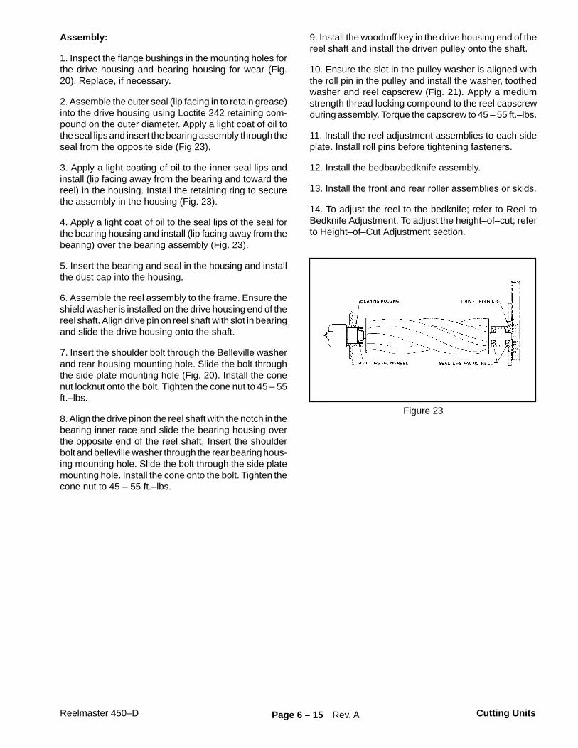
2. Assemble the outer seal (lip facing in to retain grease)into the drive housing using Loctite 242 retaining com-pound on the outer diameter. Apply a light coat of oil tothe seal lips and insert the bearing assembly through theseal from the opposite side (Fig 23).
3. Apply a light coating of oil to the inner seal lips andinstall (lip facing away from the bearing and toward thereel) in the housing. Install the retaining ring to securethe assembly in the housing (Fig. 23).
4. Apply a light coat of oil to the seal lips of the seal forthe bearing housing and install (lip facing away from thebearing) over the bearing assembly (Fig. 23).
5. Insert the bearing and seal in the housing and installthe dust cap into the housing.
6. Assemble the reel assembly to the frame. Ensure theshield washer is installed on the drive housing end of thereel shaft. Align drive pin on reel shaft with slot in bearingand slide the drive housing onto the shaft.
7. Insert the shoulder bolt through the Belleville washerand rear housing mounting hole. Slide the bolt throughthe side plate mounting hole (Fig. 20). Install the conenut locknut onto the bolt. Tighten the cone nut to 45 – 55ft.–lbs.
8. Align the drive pinon the reel shaft with the notch in thebearing inner race and slide the bearing housing overthe opposite end of the reel shaft. Insert the shoulderbolt and belleville washer through the rear bearing hous-ing mounting hole. Slide the bolt through the side platemounting hole. Install the cone onto the bolt. Tighten thecone nut to 45 – 55 ft.–lbs.
9. Install the woodruff key in the drive housing end of thereel shaft and install the driven pulley onto the shaft.
10. Ensure the slot in the pulley washer is aligned withthe roll pin in the pulley and install the washer, toothedwasher and reel capscrew (Fig. 21). Apply a mediumstrength thread locking compound to the reel capscrewduring assembly. Torque the capscrew to 45 – 55 ft.–lbs.
11. Install the reel adjustment assemblies to each sideplate. Install roll pins before tightening fasteners.
12. Install the bedbar/bedknife assembly.
13. Install the front and rear roller assemblies or skids.
14. To adjust the reel to the bedknife; refer to Reel toBedknife Adjustment. To adjust the height–of–cut; referto Height–of–Cut Adjustment section.
Figure 23

Reelmaster 450–DPage 6 – 16Cutting Units Rev. A
Roller Removal and Installation
1. Remove the fasteners securing the guard and rolleradjustment housing to the side plate (Fig. 24) or un-screw the upper cone nut and drop the threaded rod outof the adjustment housing (Fig. 25).
2. The threaded rod and collar assembly can be re-moved from the roller by sliding it off the shaft at bothends (Fig. 25).
IMPORTANT: When assembling a new roller to thecutting unit mount the roller so that the roller shaft”locknut” is on the right side of the cutting unit (Fig.25). (As viewed by the operator sitting on seat of ma-chine). This prevents the lock nut from looseningduring operation.
Figure 24
1. Guard2. Roller adjustment housing3. Side plate4. Mounting fasteners
Figure 25
1. Cone nut2. Rod and collar assembly3. Flex locknut


Commercial Products
� The Toro Company – 1995