892103 the 2001 EuroVan With the 2.8-Liter 24-Valve VR6 Engine and Electronic Stabilization Program
78
The 2001 EuroVan With the 2.8-Liter 24-Valve VR6 Engine and Electronic Stabilization Program Volkswagen of America, Inc. 3800 Hamlin Road Auburn Hills, MI 48326 Printed in U.S.A. May 2001 Self-Study Program Course Number 892103
-
Upload
eduardorojas007 -
Category
Documents
-
view
844 -
download
5
Transcript of 892103 the 2001 EuroVan With the 2.8-Liter 24-Valve VR6 Engine and Electronic Stabilization Program

The 2001 EuroVan
With the 2.8-Liter24-Valve VR6 Engineand ElectronicStabilization Program
Volkswagen of America, Inc.3800 Hamlin RoadAuburn Hills, MI 48326Printed in U.S.A.May 2001
Self-Study ProgramCourse Number 892103

Volkswagen of America, Inc.Service TrainingPrinted in U.S.A.Printed 5/2001Course Number 892103
Copyright Volkswagen of America, Inc.
All rights reserved. All information containedin this manual is based on the latest productinformation available at the time of printingand is subject to the copyright and otherintellectual properly rights of Volkswagen ofAmerica, Inc. All rights are reserved to makechanges at any time without notice. No part ofthis publication may be reproduced, stored ina retrieval system, or transmitted in any formor by any means, electronic, mechanical orphotocopying, recording or otherwise, nor maythese materials be modified or re-posted toother sites, without the prior permission of thepublisher.
All requests for permission to copy andredistribute information should be referred toVolkswagen of America, Inc.
Always check Technical Bulletins and theVolkswagen Worldwide Repair InformationSystem for information that may supersede anyinformation included in this booklet.

Table of Contents
Introduction .............................................................................. 1
2001 EuroVan, GLS and MV,MV Weekender, EuroVan Camper
VR6 Engine ................................................................................5
The 2.8-Liter 6-Cylinder 24-Valve Engine,Block and Pistons, Cylinder Head, Valve Train Operation,Variable Valve Timing, Camshaft Adjustment Valves,Why Variable Valve Timing?, Intake Camshaft Adjustment,Exhaust Camshaft Adjustment, Variable Intake Manifold,Performance Port Valve Actuation,Principles of Variable Intake Manifold Operation
Engine Management.............................................................. 27
The Motronic ME 7 System, ME 7 Architecture,Pathways, Assumed Functions, System Overview,Camshaft Position (CMP) Sensor G40 and CamshaftPosition (CMP) Sensor 2 G163, Ignition Coils 1-6 withPower Output Stages (N70, N127, N291, N292,N323, and N324)
Electronic Stabilization Program .......................................... 34
Introduction, Glossary, Control Process,The System and Its Components, System Overview,Design and Function
2001 U.S./Canadian EuroVan .................................................54
Standard Equipment List,EuroVan GLS 2.8L VR6 – 4V Technical Specifications,EuroVan MV 2.8L VR6 – 4V Technical Specifications,EuroVan Camper 2.8L VR6 – 4V Technical Specifications
Teletest .....................................................................................73
The Self-Study Program provides you with informationregarding designs and functions.
The Self-Study Program is not a Repair Manual!
For maintenance and repair work, always refer to thecurrent technical literature.
Important/Note!
New !
i


Introduction
1
New features include a new 2.8-liter24-valve VR6 engine, with four valves percylinder and variable valve timing,developing 201 horsepower (150 kW).
The addition of the Electronic StabilizationProgram (ESP) marks the first use byVolkswagen in the North American marketof this important safety feature.
The 2001 EuroVan is the continuation of thetradition begun in 1950 with the originalVolkswagen Transporter. Today’s versionoffers many new features to increasedriveability, passenger comfort, and safety.
Four versions of the EuroVan will beoffered for the U.S. market. These are theGLS, MV, MV Weekender, and the EuroVanCamper. Three versions will be offered inthe Canadian market; the GLS, MV, andMV Weekender. The EuroVan Camperwill not be offered in Canada.
2001 EuroVan
892103/002

Introduction
2
GLS and MV
892103/003
New equipment for the GLS and MVincludes:Engine
• 2.8L 201 hp (150 kW), 181 lbs-ft(245 Nm) torque, 6-cylinder VR6 24-valve,15° V, gas
• Enhanced On-Board Diagnostics (OBD II)Emissions
• On-board Refueling Vapor Recovery(ORVR)
• Transitional Low Emissions Vehicle(TLEV) emissions concept
• Premium unleaded fuel requiredTraction Control
• Anti-Slip Regulation (ASR) and ElectronicStabilization Program (ESP)
Front Brakes
• New 300 mm front brakes(from 280 mm)
Lights, Front/Rear
• Front foglights (without washers)
Tires
• P225/60 R 16 H, all seasonWheels/Covers
• New 16” alloy wheels (from 15”)Theft Deterrent
• Immobilizer III theft deterrent systemDoors
• Lockable storage box in left doorKeys
• Folding key with new designRadio/Audio
• Premium V, 6-speaker AM/FM cassettestereo sound system
Restraint System
• Child seat tether anchorage points, thirdrow (FMVSS 225)
Seating, Rear
• Two individual middle row seats replacingbench (GLS only)

Introduction
3
892103/004
New equipment for the MV Weekenderincludes:Engine
• 2.8L 201 hp (150 kW), 181 lbs-ft(245 Nm) torque, 6-cylinder VR6 24-valve,15° V, gas
• Enhanced On-Board Diagnostics (OBD II)Emissions
• On-board Refueling Vapor Recovery(ORVR)
• Transitional Low Emissions Vehicle(TLEV) emissions concept
• Premium unleaded fuel requiredTraction Control
• Anti-Slip Regulation (ASR) andElectronic Stabilization Program (ESP)
Front Brakes
• New 300 mm front brakes(from 280 mm)
Lights, Front/Rear
• Front foglights (without washers)
Tires
• P225/60 R 16 H, all seasonWheels/Covers
• New 16” alloy wheels (from 15”)Theft Deterrent
• Immobilizer III theft deterrent systemDoors
• Lockable storage box in left doorKeys
• Folding key with new designRadio/Audio
• Premium V, 6-speaker AM/FM cassettestereo sound system
Restraint System
• Child seat tether anchorage points, thirdrow (FMVSS 225)
MV Weekender

Introduction
4
Lights, Front/Rear
• Front foglights (without washers)Tires
• P225/60 R 16 H, all seasonTheft Deterrent
• Immobilizer III theft deterrent systemDoors
• Lockable storage box in left doorKeys
• Folding key with new designRestraint System
• Child seat tether anchorage points, thirdrow (FMVSS 225)
892103/005
EuroVan Camper*
New equipment for the EuroVan Camperincludes:Engine
• 2.8L 201 hp (150 kW), 181 lbs-ft(245 Nm) torque, 6-cylinder VR6 24-valve,15° V, gas
• Enhanced On-Board Diagnostics (OBD II)Emissions
• On-board Refueling Vapor Recovery(OVR)
• Transitional Low Emissions Vehicle(TLEV) emissions concept
• Premium unleaded fuel requiredFront Brakes
• New 300 mm front brakes(from 280 mm)
*Camper not available in Canada.

VR6 Engine
5
The 2.8-Liter 6-Cylinder24-Valve Engine
The 6-cylinder 24-valve engine is adevelopment of the previous generation15-degree VR6. The main mechanicaldifferences are in the cylinder headarea due to the introduction of four valvesper cylinder. Another new feature isthe introduction of a new variable valvetiming system, enabling the intake andexhaust cams to be controlledindependently. The variable intakemanifold already in use on Golf and Jettamodels equipped with the VR6 engine isbeing introduced for the first time onthe EuroVan.
892103/072
The Technical Data
Nm
320
280
240
200
160
120
80
40
lbs-ft
236
207
177
148
118
89
59
30
kW
160
140
120
100
80
60
40
20
hp
214
188
161
134
107
80
54
27
0 1000 2000 3000 4000 5000 6000 7000
Speed (RPM)
Ou
tpu
t
To
rqu
eedoCenignE KXA
ngiseD ,ekorts-ruofrednilyc-6V°51
eroB )mm0.18(ni91.3
ekortS )mm3.09(ni45.3
tnemecalpsiD mc2972(niuc3.071 3)
oitaRnoisserpmoC 1:0.01
rewoPmumixaM @)Wk051(ph102mpr0026
euqroTmumixaM @)mN542(tf-sbl181mpr0054
tnemeganaMenignEmetsyS
1.7EMcinortoM
stnemeriuqeRleuF dedaelnUmuimerPIKA19(enilosaG
)dednemmocer

VR6 Engine
6
Block and Pistons
The layout of the block is identical tothat of the previous 15-degree VR6 engine.It is made from gray cast iron with sixcylinders divided in two banks. The cylindernumbering begins at the side opposite theflywheel and on bank 1.
The pistons have a new design and thecombustion chamber is located in thecylinder head. On previous versions, the
892103/007
Bank 2 Bank 1
Oil Non-Return Valve
combustion chamber was located in thepiston crown.
The piston crowns have four recessesto prevent impact with the valves.The recesses for the intake valves aredeeper than for the exhaust valves andshould be installed facing the inside of theV on the block.

Cylinder Head
The cylinder head is a cross-flow type andhas four valves per cylinder. It has twocamshafts, one exhaust and one intake,connected by the upper timing chain.
The manufacturing technique used for thecamshafts is completely new, since theshafts are hollow with separate cam lobes.These are press fitted on the cam duringmanufacture using hydraulic pressure(hydro-forming).
VR6 Engine
7
The advantages of this camshaftmanufacturing technique are:
• Reduction of weight for the hollow shaft
• Use of material with resistance tobending for the shaft
• Use of material with specific frictioncharacteristics for the cams
892103/008
Upper Timing Chain
IntakeCamshaft
IntakeCamshaftAdjuster
Hollow ShaftExhaust Camshaft
RollerCamFollower Hydraulic
Compensator

VR6 Engine
8
In order for each camshaft to operatevalves in both cylinder banks, the valvestems have different lengths to
compensate for the difference in thedistance between the cams and thecylinder banks.
892103/009
Cylinder Head Cross-Section View, Cylinders 1, 3, and 5
IntakeValve
ExhaustValve
HydraulicCompensator
Roller CamFollower

9
892103/010
Cylinder Head Cross-Section View, Cylinders 2, 4, and 6
IntakeValve
ExhaustValve
The valves are actuated by rocker armswith integral roller cam followers, andhydraulic compensating units. Therefore,no maintenance adjustments are required.
VR6 Engine
The intake and exhaust manifolds for eachcylinder bank have different cross-sectionsto ensure that both cylinder banks receivethe same air speed and volume.

24E32A
Valve Train Operation
The timing mechanism is operated bytwo chains, two hydraulic tensioners,and five sprockets, one for each camshaft,one on the crankshaft, and two on theintermediate shaft.
The lower chain connects the crankshaftto the intermediate shaft, and the upperchain transmits the movement fromthe intermediate shaft to the camshafts.Tension on each chain is maintained by anautomatic hydraulic tensioner.
The tensioners and timing marks for theupper and lower chains are similar to thoseon the previous 2.8-liter VR6 engine.Special tool T10068 is needed to lock thetwo camshafts when doing the timing.When the camshafts or timing adjustersare dismantled and reassembled, theymust be synchronized.
Therefore, it is necessary to locate bothtiming adjusters in the setup position wheninstalling them to the camshafts. The chainmust then be installed so that the platedlinks of the top chain coincide with themarks on the sprockets.
MainBearingCap
CrankshaftTiming Marks
CamshaftTiming Marks
IntakeCamshaftAdjuster
VR6 Engine
10

VR6 Engine
892103/011
Crankshaft
Valve 1 for CamshaftAdjustment N205 Exhaust
CamshaftAdjuster
CamshaftAdjustmentValve 1(Exhaust)N318
Special ToolT10068
Tensioner forUpper Chain
IntermediateShaft
Tensioner forLower Chain
IntermediateShaftTiming Mark
11
10

VR6 Engine
12
Variable Valve Timing
All the components relating to the variabletiming system are located in the cylinderhead, at the flywheel side of the engine.
The system is composed of a support,which houses the various oil passages, twocamshaft adjusters, two solenoids (Valve 1for Camshaft Adjustment N205 andCamshaft Adjustment Valve 1 (Exhaust)N318), and the upper timing chain, whichtransmits movement from the intermediateshaft to both camshafts.
The variable timing system allowsthe opening and closing points of the
exhaust and intake valves to bemodified independently.
The camshaft timing adjustment isaccomplished using a hydraulic circuitwhich passes oil pressure to the timingadjusters. This is achieved with the aid ofthe two solenoids. Valve 1 for CamshaftAdjustment N205 controls the passage ofoil to the intake cam, and CamshaftAdjustment Valve 1 (Exhaust) N318 controlsthe passage of oil to the exhaust cam.
The Motronic Engine Control Module J220governs the operation of both solenoids.
Valve 1 forCamshaftAdjustmentN205
Intake Camshaft AdjusterUpper Timing Chain
Support
ExhaustCamshaftAdjuster
Camshaft AdjustmentValve 1 (Exhaust) N318 892103-012

VR6 Engine
13
Both timing adjusters consist of the samecomponents:
• Sprocket
• Base cylinder
• Rotor
• Cover
• Camshaft position sensor reluctor
The sprocket, base cylinder and cover arebolted together in a single assembly anddriven by the upper timing chain.
The rotor and the camshaft position sensorreluctor are fixed to the camshaft by themounting bolt. The mounting position ofthese components is unique and set withthe aid of locating lugs.
The position of the rotor in relationship tothe base cylinder is modified by the oilpressure controlled by the two solenoids.The movement of the rotor, which alsorotates the camshaft, is limited by thewidth of the chambers in the base cylinder.
The chambers for the intake and exhauston the base cylinder have different widths,consequently the intake cam shaft canrotate up to 25° (50° of crankshaft) whilethe exhaust camshaft can only rotate 11°(22° of crankshaft) from its initial position.
More information on the functionof camshaft position sensors canbe found in the Motronic ME 7system section of this SSP.
Sprocket
Camshaft
Chain
RotorCamshaft PositionSensor Reluctor
Bolt
Cover
Tooth ofBase Cylinder
Base Cylinder
892103-013

VR6 Engine
14
The oil pressure from the pump reachesthe solenoids through different passages.To ensure proper system operation, aminimum oil pressure of 10 psi (70 kPa)is required.
The solenoids direct oil to the A or Bchambers in the camshaft adjusters.
When there is pressure in the A chambers,the rotor will remain in its initial position.
When the pressure is directed to the Bchambers, the rotor moves and advancesthe opening and closing of the valves.
The solenoids have bleed orifices throughwhich the oil from the non-pressurizedcamshaft adjuster chambers can escapeduring rotation of the rotor.
Idling Position
When the engine is idling or running atless than 1200 rpm and under light load,the Valve 1 for Camshaft Adjustment N205will be in the rest position. It will directoil pressure to the A chambers of theintake camshaft adjuster, to maintain theintake rotor in its initial position.Consequently, the intake valves will open25° after top-dead-center (TDC).
During this operating condition, when thespeed does not exceed 1200 rpm, theCamshaft Adjustment Valve 1 (Exhaust)N318 is energized and oil pressure reachesthe B chambers of the exhaust camshaftadjuster, causing the exhaust rotor tomove. This provokes an advance of 22° inthe closing of the exhaust valves, or inother words, closure 25° before TDC.
Camshaft AdjustmentValve 1 (Exhaust) N318
Bleed OrificeOil Entry
Bleed Orifice
Valve 1 for CamshaftAdjustment N205
Chamber A
ExhaustCamshaftIntake CamshaftBase Plate
Support
Exhaust Camshaft AdjusterChamber BIntake Camshaft AdjusterRotor
892103/014

VR6 Engine
15
Working Position
When the engine is running above 1200rpm and under load, the position of theintake camshaft will be gradually modified,while the exhaust camshaft is returned toits initial position of 3° before TDC.
Valve 1 for Camshaft Adjustment N205is energized and it opens the oil passagesto the B chambers of the intakecamshaft adjuster.
When the oil pressure reaches theB chambers, the rotor advancesthe intake camshaft and consequently theopening point of the intake valves.The maximum advance from the initialposition is 50° or 25° before TDC.
The intake valves can operate at any pointbetween the idling position of 25° afterTDC and the maximum load position of25° before TDC.
Whenever the engine runs above1200 rpm, the Motronic Engine ControlModule J220 will deactivate the CamshaftAdjustment Valve 1 (Exhaust) N318 andallow oil pressure to pass to the Achambers of the exhaust camshaft adjuster.
Under these circumstances, the exhaustcamshaft adjuster rotor will remain in theinitial position and the exhaust valves willclose 3° before TDC.
892103/015
Chamber AChamber BIntakeCamshaftAdjuster
Oil EntryCamshaft AdjustmentValve 1 (Exhaust) N318
Valve 1 for CamshaftAdjustment N205
RotorBase Cylinder
ExhaustCamshaftAdjuster

16
VR6 Engine
The variable timing is governed by theMotronic Engine Control Module J220. Ituses the information from the followingsensors for this purpose:
• Mass Air Flow (MAF) Sensor G70• Engine Speed (RPM) Sensor G28• Camshaft Position (CMP) Sensor G40• Camshaft Position (CMP) Sensor 2 G163• Engine Coolant Temperature (ECT)
Sensor G62
The Camshaft Adjustment Valve 1 (Exhaust)N318 which controls the passage of oil tothe exhaust camshaft adjuster is switchedby the Motronic Engine Control ModuleJ220. It has two states, energized and atrest. Under these circumstances, theMotronic Engine Control Module J220switches the Camshaft Adjustment Valve 1(Exhaust) N318 using a ground signal whenthe engine is running below 1200 rpm andunder light load.
The Valve 1 for Camshaft AdjustmentN205, which controls the passage of oil tothe intake camshaft adjuster, is energizedby the Motronic Engine Control ModuleJ220 with a fixed frequency and a variablenegative duty cycle.
The Motronic Engine Control Module J220can vary the negative portion of the dutycycle period at any time based on amemorized characteristic map, using theintake air flow signal (from Mass Air Flow(MAF) Sensor G70) and the engine rpm(from Engine Speed (RPM) Sensor G28) asbase values.
The engine temperature signal (fromEngine Coolant Temperature (ECT) SensorG62) can cause a variation in thecharacteristic map. This in turn will cause avariation in the activation of the Valve 1 forCamshaft Adjustment N205 in order toadapt the variable timing system to theengine operating conditions.
Mass Air Flow (MAF)Sensor G70 and IntakeAir Temperature (IAT)Sensor G42
Engine Speed (RPM)Sensor G28
Camshaft Position(CMP) Sensor G40
Camshaft Position(CMP) Sensor 2 G163
Engine CoolantTemperature (ECT)Sensor G62

17
VR6 Engine
892103/016
Motronic EngineControl Module J220
Valve 1 for CamshaftAdjustment N205
Camshaft AdjustmentValve 1 (Exhaust) N318
The Motronic Engine Control Module J220uses signals from both Camshaft Position(CMP) Sensor G40 and Camshaft Position(CMP) Sensor 2 G163 as feedbacksignals to verify the operation of thevariable timing.
When a fault is detected in the system, theMotronic Engine Control Module J220 willplace both solenoids in the rest positionand inform the driver using the MalfunctionIndicator Lamp (MIL) K83.

18
VR6 Engine
Camshaft Adjustment Valves
The Valve 1 for Camshaft AdjustmentN205 and Camshaft Adjustment Valve 1(Exhaust) N318 are located in the timingcover and are each comprised of a coil, anucleus and a rod.
The coil gets power from the MotronicEngine Control Module J220 and creates amagnetic field which displaces the nucleus.The nucleus causes the rod to move andopen or close the oil passages.
Energizing
The Motronic Engine Control Module J220energizes each of the solenoidsindependently.
The Camshaft Adjustment Valve 1 (Exhaust)N318 modifies the passage of oil to theexhaust camshaft adjuster, and is suppliedwith electrical ground when the enginespeed does not exceed 1200 rpm.
SSP 251/044
The Valve 1 for Camshaft Adjustment N205controls the oil passage to the intakecamshaft, and is energized with a fixedfrequency signal and a variable negativeduty cycle.
Substitute Function and Self-Diagnosis
If a fault occurs in either of the solenoids,the Motronic Engine Control Module J220will deactivate the variable timing andmemorize the fault.
This will result in a loss in engine powerand an increase in harmful emissions.
This condition will be indicated to the driversince the Malfunction Indicator Lamp (MIL)K83 will remain on permanently.
Connector
Coil
RodBleed Orifice
Oil Entry
Oil Outlets
Nucleus

19
VR6 Engine
Why Variable Valve Timing?
To achieve optimum volumetric efficiencythroughout the engine’s speed range,the valves must be opened and closed atprecise points during the four-stroke Ottocycle. This is necessary to allow adequatetime for the filling and scavenging ofthe cylinders. These points are not static,but change depending on engine speedand load.
The non-adjustable camshafts used inmost passenger cars are designed toprovide a compromise in valve opening andclosing so that the engine can performsatisfactorily at all speeds. This generallyresults in an engine with a torque outputthat peaks early and declines gradually asengine speed (rpm) is increased.
Adjustable valve timing systemsovercome the limitations of static valvetiming by altering the points in thefour-stroke cycle when the valves open andclose. This allows the 2.8 liter 24 valveengine to produce higher torque throughouta wider rpm range.
During the four-stroke Otto cycle, there arefour valve events. They are:
• Intake valve opens (IVO)
• Intake valve closes (IVC)
• Exhaust valve opens (EVO)
• Exhaust valve closes (EVC)
Of the four valve events, the intake valveclosing (IVC) point is significant. It is thisevent that determines the distance into thecompression stroke the piston travelsbefore the intake valve closes. This effectsthe how much air/fuel mixture can enterthe cylinder.
The exhaust valve opening (EVO) point iscritical in determining how much of theair/fuel charge is burned during the powerstroke, and the flow of exhaust from thecylinder. The longer the valve is closed, thelonger the air/fuel mixture can burn. If thevalve opens too late, energy is wastedpumping the exhaust from the cylinder.
The exhaust valve closing (EVC) point andintake valve opening (IVO) point are not asimportant as the other valve events whenviewed separately. The importance of theEVC and IVO events is that together theydetermine the valve overlap period. This isthe time that both the intake and exhaustvalves are open simultaneously. This is acritical factor in scavenging exhaust gasesfrom the cylinder and in controllingemissions.
By using adjustable intake and exhaustcamshafts, it is possible to control thetiming of the valve events at variousengine speeds and loads. This results instrong performance and economicaloperation, while still meeting stringentemissions requirements.

VR6 Engine
20
Intake Camshaft Adjustment
When the engine is started or running atidle, the intake camshaft is adjusted to theretarded position. In this position the IVOoccurs at 25° after top-dead-center (TDC).This allows no valve overlap, and results inlow emissions and smooth engine runningat idle.
At partial load, the intake camshaft isadvanced to approximately 25° before TDC.When the intake valve timing is advanced,the IVO occurs earlier, and valve overlap isincreased. With increased valve overlaptime, the exhaust gases are not allscavenged from the combustion chamber.
This exhaust gas recirculation dilutes theincoming air/fuel charge, loweringcombustion pressure and temperaturewithout the need for an external EGR Valve.
Advancing the camshaft also means thatthe IVC occurs earlier. This is desirable atlow engine speeds and partial loads toprevent the piston from pushing the air/fuelcharge back into the intake manifold. Thiseffect, known as “reversion,” wouldseverely limit low-end torque and raiseemissions.
As engine load increases, the velocity ofthe intake air charge increases, and the IVCmust occur later in order to allow the “rameffect” of the intake air to completely fillthe cylinder. In addition, as engine speed(rpm) increases, the piston moves faster,and the time for the cylinder to becomeadequately filled becomes shorter.
Therefore, at high engine speeds and loads,the Motronic Engine Control Module J220will vary the intake camshaft timing basedon a map in the Motronic Engine ControlModule J220 which takes into accountload, rpm, and intake manifold change-overposition.
If the camshaft adjustment fails, the intakecamshaft is returned to the default positionof 25° after TDC.
Exhaust Camshaft Adjustment
Unlike the intake camshaft, the exhaustvalves are only adjusted to close at twopoints: 25° and 3° before TDC.
Early exhaust valve opening (EVO) may notallow all the power of the combustionprocess to be used. If the EVO occurs late,all the power of the combustion process isused, but power is wasted by pumping theexhaust gases from the cylinder. Theoptimum EVO varies with engine speed,and is closely related to the design of theexhaust system.
At engine speeds of less than 1200 rpm,EVC is set at the idling position of 25°before TDC, depending on load. For allother speeds, the EVC is set to 3° beforeTDC. This achieves good performancecharacteristics at full load, and a largevalve overlap to reduce emissions atpartial loading.
If the camshaft adjustment fails, theexhaust camshaft is returned to the defaultposition of 3° before TDC.

VR6 Engine
21
Variable Intake Manifold
The variable intake manifold already inuse on Golf and Jetta models equippedwith the VR6 engine is being introduced forthe first time on the EuroVan. This designincreases low rpm torque and high rpmpower by taking advantage of theself-charging or “ram effect” that existsat some engine speeds.
By “tuning” the intake manifold air ductlength, engineers can produce this rameffect for a given rpm range. A manifoldthat has two different lengths of air ductscan produce the ram effect over a broaderrpm range.
The VR6 engine uses two lengths of airducts but not in the same way as the dualpath manifolds used on other engines.Instead of using high velocity air flow in along narrow manifold duct to ram more airinto an engine at low rpm and thenopening a short, large diameter duct forhigh rpm, the VR6 engine takes advantage
TorquePort Performance Port
Performance PortValve Open
TorquePort Performance Port
Performance PortValve Closed
of the pressure wave created by thepressure differential that exists betweenthe combustion chamber and theintake manifold.
All air enters the intake manifold plenum,referred to as the torque port, and isdrawn down the long intake ducts tothe cylinders. A second plenum called theperformance port, which is attached to aset of short manifold ducts, joins the longintake ducts near the cylinder head.A performance port valve, similar in designto a throttle valve, separates theperformance port from the short ducts.
Note that the performance port does nothave any other passages to the intakemanifold other than through theperformance port valve. It does not haveaccess to the torque port and does notadmit any more air into the cylinders thanwhat is already drawn down the longintake ducts.
892103/019 892103/020

VR6 Engine
22
Performance Port Valve Actuation
Intake manifold change-over is enginespeed dependent. The Motronic EngineControl Module J220 activates the IntakeManifold Change-Over Valve N156, whichsupplies vacuum to the vacuum solenoidthat operates the performance port valve.
A vacuum reservoir and non-return valveis used to store a vacuum supply for theperformance valve operation. This isnecessary as manifold vacuum may beinsufficient to actuate the vacuum solenoidat high engine speeds.
At engine speeds below 900 rpm theperformance port is open for idling.The performance port valve is actuated.
At engine speeds between 900 rpmand 4300 rpm the performance port isclosed and the engine produces itsmaximum low end torque. Theperformance port valve is not actuated.
At engine speeds above 4300 rpm theperformance port is open. The performanceport valve is actuated.
Performance Port Valve (Open)
From Torque Port
To IntakeValve
Intake ManifoldChange-Over ValveN156
Non-Return Valve
To FuelPressureRegulator
VacuumReservoir
Signal fromMotronic EngineControl ModuleJ220
VacuumSolenoid
To Performance Port
892103/030

Torque PortPerformance Port
Intake ValveOpening
892103/021
PerformancePort ValveClosed
892103/022
Reflection Point
Intake ValveClosing
PerformancePort ValveClosed
Principles of Variable IntakeManifold Operation
After combustion has taken place in acylinder, there is a pressure differentialbetween the cylinder combustion chamberand the intake manifold.
When the intake valves open, an intakewave forms in the intake manifold. This lowpressure wave moves from the intake valveports toward the torque port at the speedof sound.
The open end of the intake duct at thetorque port has the same effect on theintake wave as a solid wall has on a ball.The wave is reflected back toward theintake valve ports in the form of a highpressure wave.
23
VR6 Engine

VR6 Engine
24
IntakeValveClosed
PerformancePort ValveClosed
PressureWaveBlocked
892103/024
At an optimal intake manifold length,the maximum pressure reaches the intakevalve ports shortly before the valves close.By this time the piston has started backup the cylinder, compressing theair/fuel mixture.
The pressure wave forces more air intothe cylinder against this rising compressionpressure, filling the cylinder with moreair/fuel mixture than would be possiblefrom just the piston moving downward onthe intake stroke alone. This adds to whatis called the self-charging or “ram effect.”
As engine speed increases, the highpressure wave will have less time to reachthe inlet port. Because the pressure waveis only able to move at the speed of sound,it will reach the intake valve ports too late.The valves will already be closed, andthe self-charging or “ram effect” cannottake place.
This problem can be solved by“shortening” the intake manifold.
892103/023
IntakeValveClosing
PressureWave
PerformancePort ValveClosed

VR6 Engine
25
Reflection Point forPerformance Port
PerformancePort ValveOpenReflection Point
for Torque Port
892103/027
PerformancePort ValveOpen
892103/025
Performance PortFilled with Air
IntakeValveClosed
Performance PortValve Open
892103/026
IntakeValveOpen
In the VR6 engine, the performance portvalve turns to the performance position atengine speeds below 900 rpm and above4300 rpm. This opens up the path to theperformance port. The performance port isdesigned so that the intake and pressurewaves will have a shorter path back to theintake valve ports.
The performance port is filled with air whenthe intake valve ports are closed.
When the intake valves open, the intakewave moves up both manifold intake ductstoward the torque port and theperformance port at the same speed.
Because the distance it must travel isshorter, the intake wave reaches the openend of the intake duct at the performanceport before it reaches the open end of theintake duct at the torque port.

VR6 Engine
26
Pressure Wave FillsPerformance Port
IntakeValveClosed
PerformancePort Valve Open
892103/029
892103/027.1
PerformancePort Valve Open
Intake ValveClosing butStill Open
Pressure Wave fromPerformance Port Chargesthe Cylinder with Air
The performance port pressure wave isreflected back toward the intake valveports, and that air is forced into thecombustion chamber before the intakevalves close.
The pressure wave arriving too late fromthe torque port is reflected by the closedintake valves and pushes its air charge upthe intake duct, filling the performance portin preparation for the next cycle.

Engine Management
27
The Motronic ME 7 System
Torque Management
The Motronic ME 7 system processeschanges in inputs to control engine torque.Any change in engine torque is interpretedas a torque demand. The ME 7 system istherefore referred to as a “torque-basedengine management system.”
Torque demands are any signalsthat require a change in thetorque output of the engine.
Torque demands are converted within theMotronic Engine Control Module J220 intosignals which are sent to system actuators,altering injection timing, ignition timing,throttle valve angle, boost control andindividual injector cutoff.
These changes affect the regulationof engine torque, affecting performance,efficiency, traction, and vehicledynamic control.
892103/031
Coordination ofTorque andEfficiencyDemands
External Torque Demands• Driver's Input• Cruise Control• Vehicle Speed Limitations• Vehicle Dynamic Control• Driveability
TorqueControl
Realizationof Desired
Torque Ignition Timing
WastegateControl
Injection Time
Individual CylinderFuel Cutoff
Throttle Angle
Internal Torque-Demands• Engine Start-Up• Idle Speed• Engine Speed Limitations• Component Protection
EfficiencyDemands

ME 7 Architecture
Torque Demands/Requests
The Motronic ME 7 system designatesfunctions via torque demands.
Torque demands can originate fromexternal sources, or internally within theMotronic Engine Control Module J220.These may include:
• Driver input
• Cruise control
• A/C demands
• ABS/ASR/ESP
• Transmission Dynamic ShiftProgram (DSP)
The Motronic ME 7 system takes intoaccount additional torque demands fromother external sources, such as:
• Automatic transmission/transaxle
• Air conditioning
• Power steering
Effects of Torque Demands on
Engine Torque
The Motronic Engine Control Module J220constantly regulates engine torque. It usessignals from multiple components tocontinually modify system actuators forthe desired engine torque.
Example:
The Motronic ECM sees that the idle speedis less than or greater than the specifiedRPM. The ECM will interpret this as atorque demand.
The Motronic ECM is able to adjust the idlespeed either through the charge air path byopening or closing the throttle valve, orthrough the crankshaft synchronous pathby advancing or retarding the ignitiontiming.
This allows for stable runningcharacteristics under continually varyingload conditions.
892103/032
Torque Reduction Torque Increase
• Traction Control
• Engine Speed Limitation
• Speed Limitation
• Power Output Limitation
• Cruise Control System
• Driving Dynamics Control Systems
• Speed Control
• Engine Braking Control
• Dash Pot Function
• Idling Control
• Driving Dynamics Control Systems
Engine Management
28
Engine Management
29
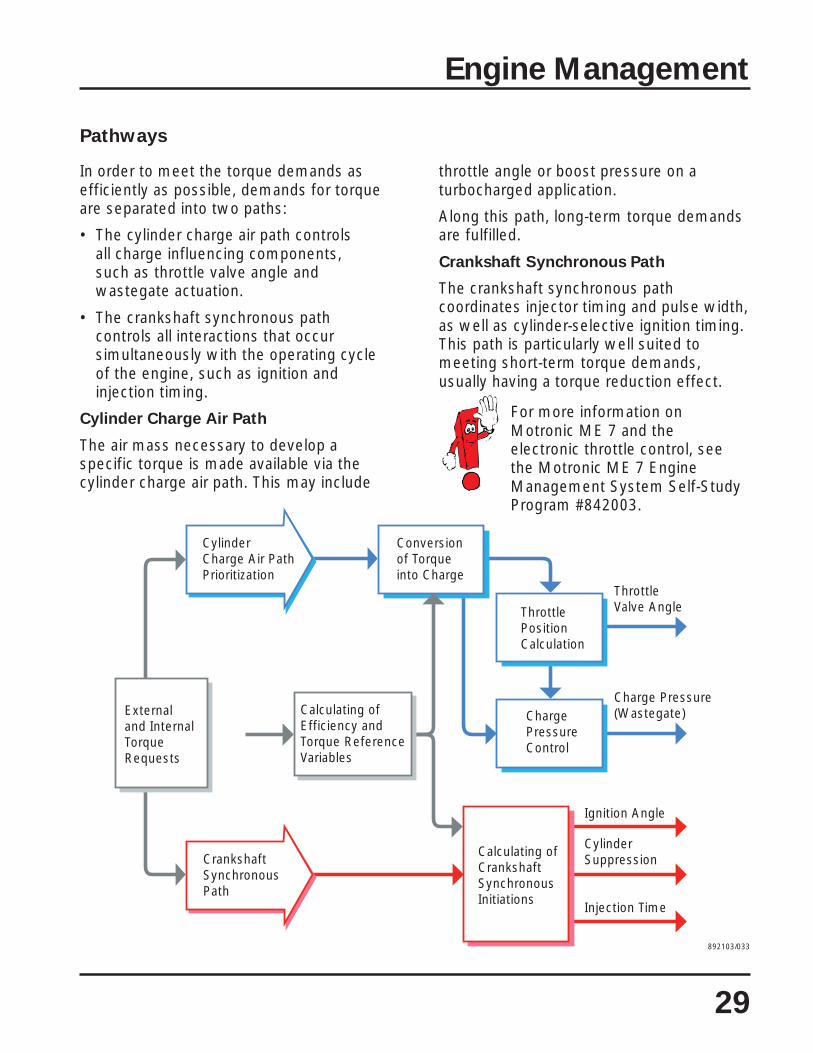
Pathways
In order to meet the torque demands asefficiently as possible, demands for torqueare separated into two paths:
• The cylinder charge air path controlsall charge influencing components,such as throttle valve angle andwastegate actuation.
• The crankshaft synchronous pathcontrols all interactions that occursimultaneously with the operating cycleof the engine, such as ignition andinjection timing.
Cylinder Charge Air Path
The air mass necessary to develop aspecific torque is made available via thecylinder charge air path. This may include
throttle angle or boost pressure on aturbocharged application.
Along this path, long-term torque demandsare fulfilled.
Crankshaft Synchronous Path
The crankshaft synchronous pathcoordinates injector timing and pulse width,as well as cylinder-selective ignition timing.This path is particularly well suited tomeeting short-term torque demands,usually having a torque reduction effect.
For more information onMotronic ME 7 and theelectronic throttle control, seethe Motronic ME 7 EngineManagement System Self-StudyProgram #842003.
892103/033
CylinderCharge Air PathPrioritization
Conversion of Torque into Charge
ThrottlePositionCalculation
ChargePressureControl
Calculating of CrankshaftSynchronousInitiations
Calculating of Efficiency andTorque ReferenceVariables
Externaland InternalTorqueRequests
CrankshaftSynchronousPath
Charge Pressure(Wastegate)
Ignition Angle
CylinderSuppression
Injection Time
Throttle Valve Angle

Engine Management
30
Assumed Functions
Fuel Injection
— Control of Injected Volume According to aCharacteristic Map.
— Sequential Injection.— Quick Start Synchronization.
— Deceleration Cutoff.— Maximum Speed Limitation.
Ignition
— Control of Ignition Advance Angle According to aCharacteristic Map.
— Selective Cylinder Knock Control.
EVAP System
— Control of Fuel Tank Emissions.— Correction by Using Lambda Adjustment (Auto-
Adaptive Subsystem).
Idle Stabilization
— Adjustment of Idling with the Aid of aCharacteristic Map (Auto-Adaptive Subsystem).
— Throttle Shutdown Dampening.— Digital Idle Stabilization.
Variable Inlet Manifold
— Control of Variable Inlet Manifold.
OBD II
— Warning Light Control.— Lambda Adjustment Control.
— Catalyzer Monitoring.— EVAP Circuit Monitoring.
— Secondary Air Injection System Monitoring.— Combustion Monitoring.
Variable Timing
— Adjustment of Variable Timing System.
Self Diagnosis
— Interrogating Fault Memory.— Basic Setting.— Final Control Diagnostics.— Measurement Value Emission.— Adaptation of the Electronic Immobilizer.— Clearance Code.
Mass Air Flow (MAF) Sensor G70Intake Air Temperature (IAT) Sensor G42
Engine Speed (RPM) Sensor G28
Camshaft Position (CMP) Sensor G40
Angle Sensor 1 for Throttle DriveG187 and Angle Sensor 2 forThrottle Drive G188
Knock Sensor (KS) 1 G61and Knock Sensor (KS) 2 G66
Oxygen Sensor (O2S) Behind ThreeWay Catalytic Converter G130
Heated Oxygen Sensor(HO2S) G39
Generator C (+ Terminal/DF)
Throttle Position (TP) Sensor G79and Sender 2 for Accelerator PedalPosition G185
Speedometer Vehicle SpeedSensor (VSS) G22Brake Light Switch F and BrakePedal Switch F47
Engine Coolant Temperature (ECT)Sensor G62
Additional Signals:— Air Conditioning On— Air Conditioning Compressor— Cruise Control
Camshaft Position (CMP) Sensor 2G163
System Overview
Sensors

Engine Management
31
Motronic EngineControl Module J220
ControlModule forAnti-TheftImmobilizerJ362
Data Link Connector(DLC) Wire ConnectorTV14
Control Module withIndicator Unit inInstrument Panel Insert J285
Fuel Pump Relay J17 andFuel Pump G6
Secondary Air Injection (AIR) Pump Relay J299and Secondary Air Injection Pump Motor V101
Inlet Manifold Change-Over Valve N156
Secondary Air Injection Solenoid Valve N122
Ignition Coils 1- 6 withPower Output Stages N70,N127, N291, N292, N323, N324
Valve 1 for Camshaft Adjustment N205
Camshaft Adjustment Valve 1 (Exhaust) N318
Cylinder 1- 6 Fuel Injectors N30, N31,N32, N33, N83, N84
Throttle Drive (Power AcceleratorActuation) G186
Evaporative Emission (EVAP) CanisterPurge Regulator Valve N80
Additional Signals:— Signal for Air Conditioning Compressor
Malfunction Indicator Lamp (MIL) K83
Fault Light for Power AcceleratorActivation K132
892103/034
Actuators

Engine Management
32
Camshaft Position (CMP) Sensor
G40 and Camshaft Position (CMP)Sensor 2 G163
Both sensors work using the Hall Principleand are located in the upper timing cover.They take their readings from the tworeluctors which rotate together with thecamshafts.Signal Application
The Camshaft Position (CMP) Sensor G40signal is used by the Motronic EngineControl Module J220 together with thesignal from the Engine Speed (RPM)Sensor G28 to synchronize the injection.At the same time, a comparison betweenthe signals from Camshaft Position (CMP)Sensor G40, Camshaft Position (CMP)Sensor 2 G163, and Engine Speed (RPM)Sensor G28 is used to monitor operationand adjust the variable timing.Replacement Function
If the signal from the Camshaft Position(CMP) Sensor G40 is missing, the signalfrom Camshaft Position (CMP) Sensor 2
G163 will be used as a reference value forinjection synchronization.If both signals should fail while the engineis running, the engine will continue to runand can be re-started. The Motronic EngineControl Module J220 uses a function called“start-up recognition” for this purpose.When the fault occurs, the Motronic EngineControl Module J220 will set fuel injectionand ignition timing based on the EngineSpeed (RPM) Sensor G28 signal. Ignitiontiming will be retarded 15 degrees as asafety precaution.If either Camshaft Position (CMP) SensorG40 or Camshaft Position (CMP) Sensor 2G163 fails, the Motronic Engine ControlModule J220 will deactivate the variablevalve timing function. Both camshafts willbe set to their initial start-up positions.A failure of either sensor will activate theMalfunction Indicator Lamp (MIL) K83 thesecond time the vehicle is started after thefault occurs.
Signals from
Both Sensors
at 2000 RPM
Camshaft Position(CMP) Sensor G40
Intake Camshaft
Exhaust Camshaft
Camshaft Position (CMP)Sensor 2 G163
G40
G163
5V
0V
5V
0V
720° Crankshaft
360°
892103/035
720°0°

Engine Management
33
Ignition Coils 1 – 6
with Power Output Stages(N70, N127, N291, N292, N323,
and N324)
The ignition system comprises six ignitioncoils with a “coil on plug” configuration.This eliminates the need for sparkplug cables.Energizing
Each ignition coil gets positive voltage fromignition terminal 15 and is grounded foroperation. The Motronic Engine ControlModule J220 sends a signal to energize theignition coil. The break in this signalgenerates the spark.Replacement Function
If any of the ignition coils are faulty,the corresponding cylinder will not beable to complete combustion. Thiscondition is picked up by the MotronicEngine Control Module J220, and it willcut off the injection to this cylinder andat the same time switch on the MalfunctionIndicator Lamp (MIL) K83.
Connector
Spark Plug Cap

Electronic Stabilization Program
34
Introduction
The electronic stabilization program (ESP) isone of the vehicle’s active safety features.
It is also known as a “driving dynamiccontrol system.”
Expressed in simple terms, ESP is an anti-skid system. It recognizes when thevehicle is in danger of skidding andcompensates when the vehicle breakstraction.
Advantages of ESP:
• ESP is not an independent system. Infact it is based on other traction controlsystems. That is why it also includes theperformance features of these systems.
• It relieves the burden on the driver.
• The vehicle remains manageable.
• It reduces the accident risk if the driveroverreacts.
Glossary
ABS
Antilock Braking System
This system prevents the wheels fromlocking while braking. Despite the system’spowerful braking effect, track stability andsteerability are retained.
ASR
Anti Slip Regulation
This system prevents the driven wheelsfrom spinning, such as on ice or gravel, byintervening with the engine managementsystem to reduce engine torque.
EBD
Electronic Brake Pressure Distribution
This system prevents overbraking of therear wheels before ABS takes effector if ABS is unavailable, due to specificfault states.
EDL
Electronic Differential Lock
This system makes it possible to driveaway on road surfaces where each wheelhas a different degree of traction by brakingthe wheel which is spinning.
ESP
Electronic Stabilization Program
This system prevents the vehicle fromskidding by selectively intervening in thebrake and engine management systems.The following abbreviations are also usedfor this type of anti-skid system:
• ASMS (Automatic StabilityManagement System),
• DSC (Dynamic Stabilization Control),• DDC (Driving Dynamic Control),• VSA (Vehicle Stabilization Assist) and• VSC (Vehicle Stabilization Control).
EBC
Engine Braking Control
This system prevents the driven wheelsfrom locking due to the engine brakingeffect when the accelerator pedal isreleased suddenly or when the vehicle isbraked with a gear engaged.

Electronic Stabilization Program
35
Control Process
Before ESP can respond to a critical drivingsituation, it must answer two questions:
A — In what direction is the driver steering?
B — In what direction is the vehiclemoving?
The system obtains the answer to thefirst question from the steering anglesensor (1) and the speed sensors at thewheels (2).
The answer to the second question issupplied by measuring the yaw rate (3) andlateral acceleration (4).
If the information received providesdifferent answers to questions A and B,ESP assumes that a critical situation canoccur and that intervention is necessary.
A critical situation can result in twodifferent types of behavior of the vehicle:
I. The vehicle threatens to understeer.
By selectively activating therear brake on the inside of the cornerand intervening in the engine andtransmission management systems,ESP prevents the vehicle fromovershooting the corner.
II. The vehicle threatens to oversteer.
By selectively activating thefront brake on the outside of the corner andintervening in the engine and transmissionmanagement systems, ESP prevents thevehicle from skidding.
SSP 204/008
A B
A = B A = B
1
2
3
4
I
II

Electronic Stabilization Program
36
As you can see, ESP can counteract bothoversteer and understeer.
To achieve this, it is necessary to initiatea change of direction without directintervention in the steering system.
The basic principle applied is the same asthat used for tracked vehicles. When abulldozer wants to negotiate a left-handbend, the track on the inside of the corneris braked and the outer track is accelerated.
To make a right-hand turn and return to theoriginal direction of travel, the track whichwas previously on the inside of the cornerand now on the outside of the corner isaccelerated and the other track is braked.
ESP intervenes along much the samelines. Here is an example of how asudden maneuver is handled by a vehiclewithout ESP.
The vehicle must avoid an obstacle whichsuddenly appears. At first, the driver steersvery quickly to the left and to thenimmediately to the right.
The vehicle swerves due to the driver’ssteering wheel movements and the rearend breaks away. The driver is no longerable to control the resulting rotation of thevehicle around its vertical axis.
892103/038
892103/041
892103/040
892103/039

Electronic Stabilization Program
37
Now let us observe how a vehicle with
ESP handles the same situation.
The vehicle attempts to avoid the obstacle.From the data provided by the sensors,ESP recognizes that the vehicle is losingstability.
The system calculates its counteractionmeasures: ESP brakes the left-hand rearwheel. This promotes the turning motion ofthe vehicle. The lateral forces acting on thefront wheels are equalized.
As the vehicle swerves to the left, thedriver steers to the right. To help the driversteer into the oversteer, the front rightwheel is braked. The rear wheels roll freelyin order to ensure an optimal buildup oflateral forces acting on the rear axle.
The preceding lane change can cause thevehicle to rotate about its vertical axis. Toprevent the rear end from breaking away,the front left wheel is braked. In highlycritical situations, the wheel may be brakedvery heavily in order to limit the buildup oflateral forces on the front axle.
Once all unstable operating states havebeen corrected, ESP ends its correctiveintervention.
892103/044
892103/043
892103/042
892103/045

Electronic Stabilization Program
38
The System and Its Components
As mentioned already, the electronicstabilization program is based on theproven traction control system.
However, it has one key additional feature:
• The system can recognize andcompensate for unstable vehicleoperating states such as skiddingat an early stage.
To achieve this, several additionalcomponents are required.
Before we explain ESP in greater detail,here is an overview of these components.
Brake Booster
Sender 1 forBrake Booster G201
Combined Sensorfor TransverseAcceleration G200 andSender for RotationRate G202

Electronic Stabilization Program
39
ABS Control Modulewith EDL/ASR/ESP J104
Steering Angle Sensor G85
ABS WheelSpeed Sensors:Right Rear G44,Right Front G45,Left Rear G46,Left Front G47
ABS Hydraulic Unit N55Hydraulic Pump forTraction Control V156
892103/046

Electronic Stabilization Program
40
System Overview
Sensors
Button for ASR/ESP E256
Brake Light Switch F
Brake Pedal Switch F47
ABS Wheel Speed Sensors:Right Rear G44,Right Front G45,Left Rear G46,Left Front G47
Steering Angle Sensor G85
Combined Sensor for TransverseAcceleration G200 and Sender forRotation Rate G202
Sender 1 for Brake Booster G201
Auxiliary Signals:Engine Management SystemTransmission Management System
ABS Control Modulewith EDL/ASR/ESPJ104, BehindInstrument Panelto Right ofClimatronic Controls
Electronic Stabilization Program
41
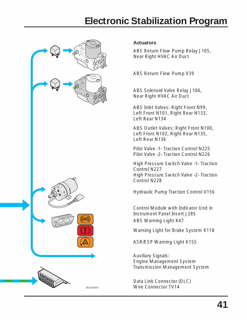
Actuators
ABS Return Flow Pump Relay J105,Near Right HVAC Air Duct
ABS Return Flow Pump V39
ABS Solenoid Valve Relay J106,Near Right HVAC Air Duct
ABS Inlet Valves: Right Front N99,Left Front N101, Right Rear N133,Left Rear N134
ABS Outlet Valves: Right Front N100,Left Front N102, Right Rear N135,Left Rear N136
Pilot Valve -1- Traction Control N225Pilot Valve -2- Traction Control N226
High Pressure Switch Valve -1- TractionControl N227High Pressure Switch Valve -2- TractionControl N228
Hydraulic Pump Traction Control V156
Control Module with Indicator Unit inInstrument Panel Insert J285ABS Warning Light K47
Warning Light for Brake System K118
ASR/ESP Warning Light K155
Auxiliary Signals:Engine Management SystemTransmission Management System
Data Link Connector (DLC)Wire Connector TV14892103/047

Electronic Stabilization Program
42
Design and Function
Control Cycle
The ABS wheel speed sensors provide acontinuous stream of data on speeds foreach wheel.The steering angle sensor is the onlysensor which supplies data directly via theCAN data bus to the control module. Thecontrol module calculates the desiredsteering direction and the required handlingperformance of the vehicle from both setsof information.The sensor for transverse accelerationsignals to the control module when thevehicle breaks away to the side, and thesender for rotation rate signals when thevehicle begins to skid. The control modulecalculates the actual state of the vehiclefrom these two sets of information.If the nominal value and actual value do notmatch, ESP performs correctiveintervention calculations.
1 ABS Control Module withEDL/ASR/ESP J104
2 ABS Hydrualic Unit N55 withHydraulic Pump for Traction ControlV156
3 Sender 1 for Brake Booster G2014 Sensor for Tranverse Acceleration
G200 (Combined with G202)5 Sender for Rotation Rate G202
(Combined with G200)6 Button for ASR/ESP E2567 Steering Angle Sensor G858 Brake Light Switch F
9-12 ABS Wheel Speed Sensors G44, G45,G46, G47
13 Data Link Connector (DLC)Wire Connector TV14
14 Warning Light forBrake System K118
15 ABS Warning Light K4716 ASR/ESP Warning Light K15517 Vehicle and Driver Behavior18 Intervention in Engine Management19 Intervention in Transmission Control
Module (TCM) J217 (Vehicles withAutomatic Transmission Only) 892103/048
ESP decides:
• what wheel to brake or accelerate and towhat extent,
• whether engine torque is reduced and• whether the transmission control module
is activated on vehicles withautomatic transmission.
The system then checks to see ifintervention was successful from the data itreceives from the sensors.If intervention was successful, ESP ends itand continues to monitor the vehicle'shandling characteristics.If unsuccessful, the intervention cycleis repeated.When corrective intervention is takingplace, this is indicated to the driver by theflashing ASR/ESP warning light.
3
4
6
5
7
8
9
10
17
11
12
13 14 15 16
1
2
18
19
CONTROL
ESP
ABS
ASR EDL EBD MSR
MONITORING

Electronic Stabilization Program
43
ABS Control Module with
EDL/ASR/ESP J104
In the Bosch ESP system, the controlmodule and the hydraulic unit areseparated. The control module is locatedbehind the right side of the instrumentpanel near the HVAC housing.
Design and function
The ABS control module comprises ahigh-performance microcomputer.
Since a high level of fail-safety is required,the system has two processors as well asits own voltage monitoring device and adiagnostics interface.
The two processors use identical softwarefor information processing and formonitoring each other.
Dual-processor systems of this type havewhat is known as active redundancy.
Electric circuit
The ABS Control Module with EDL/ASR/ESP J104 obtains its power supply via thepositive connection in the dash panel wiringharness.
Effects of failure
In the unlikely event of control modulefailure, the driver will only have use of thestandard brake system without ABS, EDL,ASR and ESP.
Self-diagnosis
The following faults are detected:
• Control module defective• Power supply failure
892103/050
892103/049
S
A/+
J104

Steering Angle Sensor G85
is mounted on the steering columnbetween the steering column switch andthe steering wheel. The Airbag SpiralSpring / Return Spring with Slip Ring F138is integrated in the Steering Angle SensorG85 and located on its base.
892103/052
Airbag Spiral Spring / ReturnSpring with Slip Ring F138
892103/051
Task
The sensor transfers the steering wheellock angle to the ABS Control Module withEDL/ASR/ESP J104. A measured angle of±720° corresponds to four full turns of thesteering wheel.
Electric circuit
Steering Angle Sensor G85 is the onlysensor of the ESP system which transfersinformation directly via the CAN data bus tothe control module. After switching on theignition, the sensor initializes itself as soonas the steering wheel has been rotatedthrough an angle of 4.5°. This is equivalentto a turning movement of approximately0.6 inch (15 mm).
Effects of failure
Without the information supplied by theSteering Angle Sensor G85, ESP would beunable to determine the desired direction oftravel. The ESP function fails.
Self-diagnosis
After replacing the control module orthe sensor, the zero position mustbe recalibrated.
Faults can include:• Steering angle sensor – no communication• Wrong setting• Mechanical fault• Defective• Implausible signal
Faults can occur if the track hasbecome maladjusted. Make surethat the sensor is connectedsecurely to the steering wheel.
Electronic Stabilization Program
44
J105
J106
G85
S
J104

Electronic Stabilization Program
45
Design
The angle is measured using the principleof the light barrier.
The basic components are:• a light source (A)• an encoding disc (B)• optical sensors (C and D)• a counter (E) for full revolutions
The encoding disc comprises two rings:the absolute ring and the incremental ring.Both rings are scanned by twosensors each.
Function
We can simplify the setup by arrangingan incremental hole template (1) and anabsolute hole template (2) side by side.The light source (3) is positioned inbetween the hole templates. The opticalsensors (4 and 5) are located onthe outside.
Light shining on a sensor through a gapgenerates a signal voltage. If the lightsource is covered, the voltage dropsdown again.
Moving the hole templates produces twodifferent voltage sequences. Theincremental sensor supplies a uniformsignal, since the gaps follow each other atregular intervals. The absolute sensorgenerates an irregular signal, since lightpasses through the gaps in the template atirregular intervals. By comparing bothsignals, the system can calculate how farthe hole template has moved. The absolutevoltage sequence determines the startingpoint of the movement.
Designed to send a usable signal to thecontrol module for one steering wheelrotation in one direction at a time, thesteering angle sensor uses the sameprinciple.
892103/053
E
892103/056
892103/055
B
D
A
C
892103/054
1
4
3
5
2

Electronic Stabilization Program
46
Combined Sensor for
Transverse Acceleration G200 and
Sender for Rotation Rate G202
is mounted at the base of the passengerside ‘A’ pillar. This component containssensors to measure both lateralacceleration and steering yaw rate.Both sensors are mounted on a printedcircuit board and operate according tomicro-mechanical principles.
The Sensor for Transverse AccelerationG200 determines whether and to whatextent lateral forces are causing the vehicleto lose directional stability.
The Sender for Rotation Rate G202 mustdetermine if the vehicle is rotating about itsvertical axis. This process is known asmeasuring the yaw rate.
Effects of failure
Without these signals, the actual vehicleoperating state cannot be calculated in thecontrol module. The ESP function fails.
Self-diagnosis
The diagnosis establishes whether an opencircuit has occurred, or a short circuit topositive or ground exists.
The system is also able to determinewhether the sensor is defective or not.
892103/057
This sensor is highly sensitiveto damage.

Electronic Stabilization Program
47
Design of Sensor for Transverse
Acceleration G200
The sensor is a tiny component on theprinted circuit board of the combinedsensor.
Expressed in simple terms, the Sensor forTransverse Acceleration G200 is a capacitorplate with a moving mass which issuspended so that it can move back andforth. Two additional permanently mountedcapacitor plates enclose the movable plateto form two series-connected capacitors(K1 and K2). The quantity of electricitywhich the two capacitors can absorb cannow be measured by means of electrodes.This quantity of electricity is known ascapacitance C.
Function
As long as no acceleration acts on thissystem, the measured quantities ofelectricity (C1 and C2) of the two capacitorsare of equal magnitude.
If lateral acceleration acts on the system,the inertia of the movable mass at thecenter plate causes the part opposite thefixed plate to move against the direction ofacceleration. This causes the spacingbetween the plates to change and this alsochanges the measured quantities ofelectricity of each of the capacitors.
The spacing of the plates at capacitor K1increases and the associated capacitanceC1 decreases.
The spacing of the plates at capacitorK2 decreases and capacitance C2therefore increases.
K1
892103/060
892103/059
892103/058
C1 < C2
Stationary PlateCapacitor Plate withMovable Mass
Suspension
K2
StationaryPlate
Electrode
Directionof Travel
C1 = C2 C1
C2
K1
K2
K1
K2
C1
C2

Electronic Stabilization Program
48
Design of Sender for Rotation Rate G202
The Sender for Rotation Rate G202is mounted on the same board, but isotherwise separate from the Sensor forTransverse Acceleration G200.
This design can also be explained insimple terms.
Imagine a vibrating mass suspended in asupport between the north and south polesof a constant magnetic field. Printed circuitscomprising the actual sensor are attachedto this vibrating mass.
In the actual sender, this configuration isduplicated for reliability.
Function
If you apply an AC voltage (V~), the partcontaining the conductors begins tooscillate in the magnetic field.
If angular acceleration acts on thisstructure, the oscillating mass ceases tooscillate back and forth. Since this occurs ina magnetic field, the electrical behavior ofthe conductors changes.
When measured, this change showsthe magnitude and direction of thevehicle’s rotation around its vertical axis.The evaluation electronics calculate theyaw rate from this data.
Directionof Travel
South Pole
Vibrating Mass
Conductors
North Pole
892103-061
892103/062
V~
Linear Vibration Corresponding toAC Voltage Applied
Yaw Rate
Coriolis Acceleration
V~
892103/063
Substrate

Electronic Stabilization Program
49
Sender 1 for Brake Booster G201
is threaded into the Hydraulic Pump forTraction Control V156.
Task
The Sender 1 for Brake Booster G201signals the momentary pressure in thebrake circuit to the control module.From this, the control module calculatesthe wheel braking forces and thelongitudinal forces acting on the vehicle. IfESP intervention is necessary, the controlmodule allows for this value whencalculating the lateral forces.
Electric circuit
The Sender 1 for Brake Booster G201 isconnected to the ABS Control Module withEDL/ASR/ESP J104 by three wires.
Effects of failure
Without values for current brake pressure,the system is no longer able to calculatethe lateral forces correctly. The ESPfunction fails.
Self-diagnosis
The diagnosis establishes whether an opencircuit exists or whether a short circuit topositive or ground has occurred. Thesystem is also able to recognize whetherthe sensor is defective.
892103/064
892103/065
Do not remove the senderfrom the hydraulic pump.
It must be replaced togetherwith the pump.
G201
J104

Electronic Stabilization Program
50
Button for ASR/ESP E256
This button is located on the instrumentpanel, just above the radio.
It allows the driver to deactivate theESP function. When the driver depressesthe brake pedal or presses the buttonagain, it reactivates the ESP function.If the driver forgets to reactivate ESP, thesystem reactivates itself when theengine is restarted.
It makes sense to deactivate the ESPfunction in the following situations:
• when trying to free the vehicle fromdeep snow or loose surfaces byrocking the vehicle back and forth,
• when driving with snow chainsinstalled, and
• to run the vehicle on a dynamometer.
The system cannot be deactivated whileESP intervention is in progress or above acertain speed.
Effects of failure
If the button is defective, the ESP functioncannot be deactivated. A malfunction isindicated on the Instrument Panel ControlModule with Indicator Unit in Insert J285 bythe ASR/ESP Warning Light K155.
Self-diagnosis
The self-diagnosis cannot detect adefective button.
892103/066
892103/067
Electric circuit
S
+
J104
E256L71

Electronic Stabilization Program
51
The Hydraulic Pump for
Traction Control V156
is mounted below the ABS Hydraulic UnitN55 in the engine compartment on acommon support.
Task
In an ABS system, a small quantity ofbrake fluid must be pumped through thebrake master cylinder against a highpressure. This task is performed by thereturn flow pump. However, the return flowpump cannot provide a large quantity ofbrake fluid at low or zero pedal pressurebecause the brake fluid has a viscosity thatis too high at low temperature.
The ESP system therefore requires anadditional hydraulic pump in order to buildup the necessary pre-pressure on thesuction side of the return flow pump.
The pressure for pre-charging is limitedby an orifice in the master cylinder. Thehydraulic pump itself is not regulated.
Electric circuit
Both wires of the hydraulic pump areconnected to ABS Control Module withEDL/ASR/ESP J104.
Effects of failure
The ESP function can no longer beexecuted. ABS, EDL and ASR functions arenot impaired.
Self-diagnosis
The self-diagnosis indicates open circuit aswell as short circuit to positive and ground. Do not repair the hydraulic pump.
It must be replaced as a unit.
As a replacement part, the pumpis already filled with brake fluid.Do not remove the plugprematurely. Do not use anempty hydraulic pump.
892103/068
892103/069
J104
V156

The ABS Hydraulic Unit N55
is mounted on a support in the enginecompartment. The exact location may varydepending on vehicle type.
Task
The hydraulic unit has two diagonally splitbrake circuits.
Compared with older ABS units, thehydraulic unit has been modified by theaddition of a changeover valve and anintake valve for each brake circuit. Thereturn flow pump is now self priming.
The changeover valves are as follows:
Pilot Valve -1- Traction Control N225Pilot Valve -2- Traction Control N226The intake valves are as follows:High Pressure Switch Valve -1- TractionControl N227High Pressure Switch Valve -2- TractionControl N228
The individual wheel brake cylinders areactivated by the valves in the hydraulic unit.Three states are possible by activating thehydraulic unit inlet and outlet valves for awheel brake cylinder:
• Raise pressure• Hold pressure• Reduce pressureEffects of failure
If proper functioning of the valvescannot be assured, the complete systemis deactivated.
Self-diagnosis
Changeover and intake valves are eachchecked for open circuit and short circuitto positive and ground.
892103/070
Electronic Stabilization Program
52

Electronic Stabilization Program
53
Warning Lights and Buttons
in the Diagnosis
If a fault occurs while ESP correctiveintervention is in progress, the system triesits best to complete corrective intervention.At the end of the corrective process, thesubsystem is deactivated and the warninglight is activated.
Faults and activation of warning lights arealways saved to the fault memory.
The ESP function can be deactivated bypressing the Button for ASR/ESP F47.
Warning Lights
Warning Light forBrake System K118
ABS Warning Light K47
ASR/ESP Warning Light K155
892103/900
K118 K47 K155Ignition "on"
System OK
ASR/ESP intervention
Button for ASR/ESP E256 “off”ABS remains active,ESP is deactivated when coasting and accelerating,but remains active during ABS intervention.
ASR/ESP failureFault at Sender for Rotation Rate G202, Sensor forTransverse Acceleration G200, Steering AngleSensor G85, or Sender 1 for Brake Booster G201;in event of ABS failure, emergency ESP functionremains active.EBD remains active.
ABS failureAll systems switch off.

2001 U.S./Canadian EuroVan
Standard Equipment ListS: Standard, at no additional charge. O: Option, at additional charge.P: Part of option package, at additional charge. — : Not available.
roiretxE SLG VM *repmaC
annetnA annetnaelbispalloc,detnuomtnorF S S S
gnigdaB raeR,ediSrevirDegdaBVM — S —
sthgiLekarB wodniwraerfopotnipmalpotsdetnuomhgihretneC S S S
srepmuB srepmubrolocydoB S S S
srooD )edis1,tnorf2(srood3 S S S
seldnahroodkcalB S S S
wodniwssalghtiwroodhctahraeR S S S
ssalG kcabrallip-BmorfycavirprofssalgdetnitkraD)rednekeeWhtiwelbaliavaton(
S S —
neerg,ssalgdetniT S S S
ellirG ogolretnechtiwellirgrolocydoB S S S
nroH snrohenotlauD S S S
raeR/tnorF,sthgiL ,elcihevfopu-tratsnopU.)LRD(sthgiLgninnuRemityaDtnemurtsni;rewopdecuderhtiwdegagneerasthgildaeh
.ffoniamersthgilliatdnasthgilgnikrap,gnithgillenaphctiwsthgilehtrewopllufhtiwsthgilllaegagneoT
.noitisopnootdenrutebtsum
S S S
)srehsawtuohtiw(sthgilgoftnorF S S S
snelssalg,spmaldaehnegolaH S S S
s'revirdfognineponopu,enotgninrawno-sthgildaeHdevomersiyeknoitinginehwrood
S S S
srorriM sgnisuohrorrimrolocydoB S S S
elbataeh,srorrimrewopedisregnessap&revirD S S S
slenaP/sgnidloM rolocydobnilenapetalpesnecil/eldnahetagtfiL S S S
tniaP tniapcillateM O O —
tniapcillatem-noN S S S
54
*Camper not available in Canada.

2001 U.S./Canadian EuroVan
Standard Equipment ListS: Standard, at no additional charge. O: Option, at additional charge.P: Part of option package, at additional charge. — : Not available.
55
roiretxE SLG VM *repmaC
fooR —edahsnushtiw)redilspoT(foornusrewoPegakcaprednekeeWhtiwelbaliavaton
O O —
srabnwod-eithtiwreirracegaggulpotfooR — — S
seriT erit/leehwerapsleetsezislluF S S S
nosaeslla,H61R06/522P S S S
srevoC/sleehW )"51morf(sleehwyolla"61weN S S —
)"51morf(sleehwleets"61weN — — S
srehsaW/srepiW elbammargorp,deeps-4htiwsrepiwdleihsdniwdeeps2erutaefepiwtnettimretni
S S S
)tnorf(elzzonrehsawdleihsdniwdetaeH S S S
tnettimretnihtiwmetsysrehsaw/repiwraeRerutaefepiw
S S S
roiretnI
gninoitidnoCriA tnemecalpsidelbairavhtiw,eerf-CFC,gninoitidnocriArosserpmocC/A
— P S
gninoitidnocriacitamotuacinortcele:cinortamilC,)raerdnatnorf(enozlaud,eerf-CFC,metsys
htiwelbaliavatoN.raernislortnocetarapesdna.egakcaPrednekeeW
S S —
tfeht-itnA/mralA )IIIrednopsnarT(metsystnerretedtfehtrezilibommI S S S
tsermrA taestnorfhcaerof)2(stsermragnidloF S S S
rethgiL/yarthsA elosnocretnecfotnorfniyarthsadetanimullI S S S
slenapedisraernisyarthsaraerowT S S S
seldnaHtsissA ,)1(rallip-Bregnessapdna)2(srallip-AnoseldnahtsissAsrallip-Cnoparts,renildaehnieldnahbargregnessap
)4(skoohtaoc,)2(
— S —
eldnahbargregnessap,)2(srallip-AnoseldnahtsissArenildaehni
— — S
,)1(rallip-Bregnessapdna)2(srallip-AnoseldnahtsissAregnessapnoparts,renilldaehnieldnahbargregnessap
)4(skoohtaoc,)1(rallip-Cedis
S — —
elosnoCretneC egarotS,roiretnIeeS — — —
*Camper not available in Canada.
Standard Equipment ListS: Standard, at no additional charge. O: Option, at additional charge.P: Part of option package, at additional charge. — : Not available.
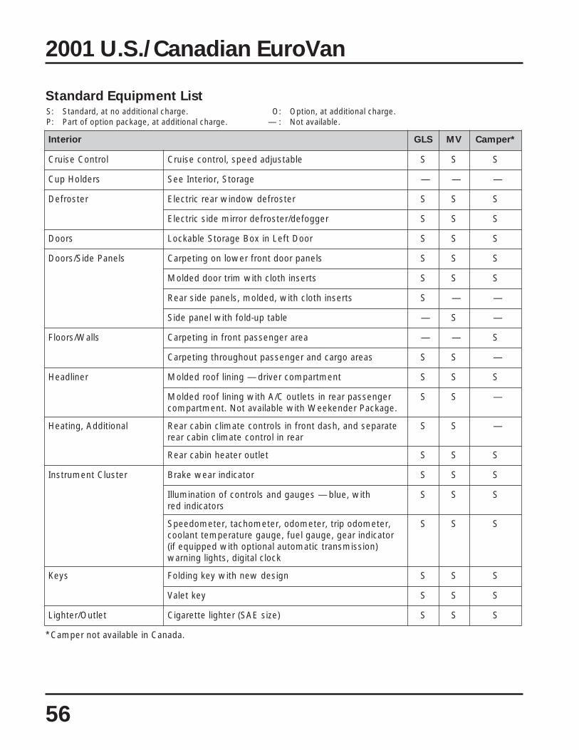
56
roiretnI SLG VM *repmaC
lortnoCesiurC elbatsujdadeeps,lortnocesiurC S S S
sredloHpuC egarotS,roiretnIeeS — — —
retsorfeD retsorfedwodniwraercirtcelE S S S
reggofed/retsorfedrorrimediscirtcelE S S S
srooD rooDtfeLnixoBegarotSelbakcoL S S S
slenaPediS/srooD slenaproodtnorfrewolnognitepraC S S S
stresnihtolchtiwmirtrooddedloM S S S
stresnihtolchtiw,dedlom,slenapedisraeR S — —
elbatpu-dlofhtiwlenapediS — S —
sllaW/sroolF aeraregnessaptnorfnignitepraC — — S
saeraogracdnaregnessaptuohguorhtgnitepraC S S —
renildaeH tnemtrapmocrevird—gninilfoordedloM S S S
regnessapraernisteltuoC/AhtiwgninilfoordedloM.egakcaPrednekeeWhtiwelbaliavatoN.tnemtrapmoc
S S —
lanoitiddA,gnitaeH etarapesdna,hsadtnorfnislortnocetamilcnibacraeRraernilortnocetamilcnibacraer
S S —
teltuoretaehnibacraeR S S S
retsulCtnemurtsnI rotacidniraewekarB S S S
htiw,eulb—seguagdnaslortnocfonoitanimullIsrotacidnider
S S S
,retemodopirt,retemodo,retemohcat,retemodeepSrotacidniraeg,eguagleuf,eguagerutarepmettnalooc
)noissimsnartcitamotualanoitpohtiwdeppiuqefi(kcolclatigid,sthgilgninraw
S S S
syeK ngisedwenhtiwyekgnidloF S S S
yektelaV S S S
teltuO/rethgiL )ezisEAS(rethgiletteragiC S S S
2001 U.S./Canadian EuroVan
*Camper not available in Canada.

Standard Equipment ListS: Standard, at no additional charge. O: Option, at additional charge.P: Part of option package, at additional charge. — : Not available.
57
roiretnI SLG VM *repmaC
gnithgiL sthgilemodraer2 S S —
sthgilgnidaerraer2 S — —
)elbatgnidlofrevo(aeraregnessaprofthgiltnecseroulF — S —
yellagrevognithgiltnecseroulF — — S
elbahctiws,noitanimullipetsecnartneediS S S S
skcoL metsysgnikcolrewoplartneC S S S
roodgnidilsedisnokcolytefasdlihC S S S
pacleufgnikcoL S S S
metsysgnikcolrewoplartnecetomeR S S S
roiretnI,srorriM ytinavrosivdetanimulliregnessaptnorfdnarevirDsrevochtiwsrorrim
S S S
noitatnemanrO ekarbkraprofnottubemorhC S S S
bonktfihsnognirdnaseldnahroodroiretniemorhC S S S
steltuOrewoP egagguldnaregnessapniskcajrewoplanoitiddAstnemtrapmoc
S S S
kcajrewop/rethgiletteragiC S S S
oiduA/oidaR ogabenniWmorfmetsysdnuosoeretsDCMF/MA — — O
oeresettessacMF/MArekaeps6,VmuimerPmetsysdnuos
S S —
elbispalloc&srekaeps6(noitaraperpmetsysdnuoSoidarfonoitallatsniogabenniWhtiw,)annetna
— — S
metsyStniartseR raerdnatnorfrofsrotcartergninoisnetcitamotuAecalpnitaesdlihcerucesot,stlebytefasregnessap
S S S
latnemelppusgabriatnorfregnessaptnorfdnarevirDmetsystniartser
S S S
,stlebytefastniop-3tnorfelbatsujdathgieHdetanidroocroloc
S S S
stlebpalhtiwstaesgnicaf-raertnemtrapmocregnessaP — S —
,stlebytefastniop-3wordrihttnemtrapmocregnessaPtlebpalretnec
S S —
2001 U.S./Canadian EuroVan
*Camper not available in Canada.

Standard Equipment ListS: Standard, at no additional charge. O: Option, at additional charge.P: Part of option package, at additional charge. — : Not available.
58
roiretnI SLG VM *repmaC
)d'tnoC(metsyStniartseR tnorf,sretimildaolhtiwsrenoisnet-erptlebytefaSylnostaes
S S S
driht,stniopegarohcnarehtettaesdlihC—adanaC/SU)522SSVMF(wor
S S S
tnorF,gnitaeS noitcnufleviwshtiwtaestnorfregnessapdnarevirDtnemtsujdarabmullaunamdna
— — S
staestnorfelbataeH O O —
raeR,gnitaeS htiwstaesgnicaf-raergnidlofelbavomer2,worelddiMstserkcabelbatsujdadnastsermralaud
— S —
,owtrofdeb"34x"47aotstrevnoc,hcnebecalp-2raeRdrawrofrodrawraersecaf
— — S
)elbavomer(debotstrevnoc,hcnebecalp-3raeR — S —
retnec2htiwelbmutdnadlof,hcnebecalp-3raeRstsermra
S — —
elbatsujdaelgnadnathgieh,stniartserdaehhcnebraeR S — —
elbatsujdathgieh,stniartserdaehhcnebraeR — S S
nihcnebnosrep-2(hcnebretnecelbavomeR)wordnoces
— — O
hcnebgnicalperstaesworelddimlaudividniowT S — —
serutaeFlaicepS ,debnosrep-2htiwfoorpu-poP:egakcaPrednekeeW,sneercswodniw,)ylnotnorf(gninoitidnocrialaunam
taesnirotaregirferhtiwtaesgnicafraeredisrevirddexifwodniwgnidils,rotarenegA021,yrettabdnoces,esab
hctahraerrofneercs,sniatruc
— P —
leehWgnireetS leehwgnireetsdeddapekops-4 S S S
tcapminopuelbispalloc/elbamrofedleehwgnireetS S S S
nmulocgnireetstnerreted-tfehT S S S
egarotS tnemtrapmocregnessapni)1(redlohegareveB S — S
tnemtrapmocregnessapni)2(sredlohegareveB — S —
srenilrebburhtiwstekcopegarotsroodtnorF S S S
tekcopegarots/enizagamkcabtaestnorF S S S
)ediss'revirD(rooDtfeLnixoBegarotSelbakcoL S S S
2001 U.S./Canadian EuroVan
*Camper not available in Canada.

Standard Equipment ListS: Standard, at no additional charge. O: Option, at additional charge.P: Part of option package, at additional charge. — : Not available.
59
roiretnI SLG VM *repmaC
)d'tnoC(egarotS )ediss'revird(stekcopegarotstnemtrapmocregnessaP S S —
draobhsadforetnecmottobnitnemtrapmocegarotS S S S
aerAograC/knurT revocegaggulaeraograC S — —
tnemtrapmocogracnignirevocroolftepraC S S —
)gnisolctsissaot(dilknurtfoedisninopirG S S S
foesab(smetignolfognidaolroferutaefhguorht-ssaP)taeshcneb
S — —
flehsegaggultnemtrapmocogracraeR — S —
)4(skoohnwod-eitegagguldesseceR S S —
tnemtrapmocogracnignirevocroolfrebbuR — — S
tesolcebordraW — — S
yretslohpU cirbaftaesruolev"tamroF" S S —
cirbaftaeshtolcnevowtalf"tibrO" — — S
metsySnoitalitneV retliftsuddnanelloP S S S
teltuoretaehnibacraeR S S S
swodniW htiwswodniwtnorfrewophcuot-enocitamotuAnoitcetorphcnip
S S S
detaelpdnasniatrucycavirpraerdnatnorFsedahswodniw
— — S
swodniwelddimgnidilshtiwtnemtrapmocregnessaP S S —
swodniwedisrofsniatrucno-panS — S —
swodniwdeneercsowT — — S
ogabenniW ).tf.uc2(rotaregirfersagPL/CD/CA — — S
AoWVecalpertonseod(dradnats—yartegareveBtaesregnessapfoedisno,)redlohpuc
— — S
snwod-eitegarotsbaC — — S
foorpu-popniowtrofdeb"34x"47ezis-lluF — — S
srotcetededixonomnobracdnasagPL — — S
2001 U.S./Canadian EuroVan
*Camper not available in Canada.

Standard Equipment ListS: Standard, at no additional charge. O: Option, at additional charge.P: Part of option package, at additional charge. — : Not available.
60
2001 U.S./Canadian EuroVan
roiretnI SLG VM *repmaC
)d.tnoC(ogabenniW deneercshtiwsllaw-edissavnacsahfoorpu-poPsediseerhtnoswodniw
— — S
gniliecotroolffo'7otpuetaercotsesirfoorpu-poPtnevfoortuo-pithtiw/moor
— — S
nihcnebnosrep-2(hcnebretnecelbavomeR)wordnoces
— — S
)wordnocesrof(taesnoinapmocelbavomeR — — O
potretnuocdnaknisleetssselniatS — — S
egarotsdraobdebknubpoT — — S
selbatytilitu/gninidelbatsujda-itlumowT — — S
leetssselniatshtiwevotssagPLrenrub-owTdleihsrettalps
— — S
lacinhceT
sekarB )metsysgnikarbkcol-itna(SBA S S S
)531SSVMF(dradnatSekarBdezinomraH S S S
)mm082morf(sekarbmm003weN S S S
dilosraer,sekarbcsiddetnevtnorfdetsissarewoPsekarbcsid
S S S
snoissimE IIDBO S S S
yrevoceRropaVgnileufeRdraob-nORVRO S S S
tpecnocsnoissimeVELT S S S
enignE ,euqrot)mN542(tf-sbl181,)Wk051(ph102L8.2sag,V°51,V4–6RVrednilyc-6
S S S
ainrofilaC—scitsongaiDdraoB-nOdecnahnE S S S
tnemtrapmocenignenisturtssaG S S S
6VdnaogolWVhtiwrevocenigneweN S S S
deriuqerleufdedaelnumuimerP S S S
tcapmIediS smaebroodedisnoisurtni-itnA S S S
gnireetS gnireetsnoinipdnakcardetsissarewoP S S S
*Camper not available in Canada.

Standard Equipment ListS: Standard, at no additional charge. O: Option, at additional charge.P: Part of option package, at additional charge. — : Not available.
61
2001 U.S./Canadian EuroVan
roiretnI SLG VM *repmaC
noisnepsuS srebrosbakcohscipocseletraerdnatnorF S S S
rabrezilibatstnorF S S S
noisnepsusrabnoisrottnorftnednepednI S S S
noisnepsusraertnednepednI S S S
lortnoCnoitcarT cinortcelE(PSEdna)noitalugeRpilS-itnA(RSA)margorPnoitazilibatS
S S —
)kcoLlaitnereffiDcinortcelE(LDE S S S
noissimsnarT kcoltfihscitamotuahtiw,evitpada,citamotuadeeps-4 S S S
*Camper not available in Canada.

Standard Equipment ListS: Standard, at no additional charge. O: Option, at additional charge.P: Part of option package, at additional charge. — : Not available.
2001 U.S./Canadian EuroVan
adanaC–ytnarraW SLG VM *repmaC
noisorroC-itnA tsniagAytnarraWdetimiLecnatsiddetimilnuraey8noitarofrePnoisorroC
S S —
ecnanetniaM egrahcon)tsrifsruccorevehcihw(mk000,04/raey2ecnanetniams'rerutcafunamdeludehcs
S S —
ytnarraWniartrewoP detimiL)tsrifsruccorevehcihw(mk000,08/raey5.ytnarraWniartrewoP
tneuqesbusdnatsrifrofegarevocmk000,08/raey5.adanaCnisrenwo
S S —
ecnatsissAedisdaoR ecnatsissaedisdaorruoh-42ecnatsiddetimilnu/raey2 S S —
ytnarraWelciheV weNdetimiL)tsrifsruccorevehcihw(mk000,04/raey2stnemtsujdadnasmetiraet&raeW.ytnarraWelciheV
mk000,02roshtnom21laitiniretfadedulcxe.)tsrifsruccorevehcihw(
S S —
)kcoLlaitnereffiDcinortcelE(LDE S S —
SU–ytnarraW SLG VM *repmaC
noisorroC-itnA tsniagAytnarraWdetimiLecnatsiddetimilnuraey8noitarofrePnoisorroC
S S S
ecnanetniaM egrahcon)tsrifsruccorevehcihw(elim000,42/raey2ecnanetniams'rerutcafunamdeludehcs
S S S
ytnarraWniartrewoP detimiL)tsrifsruccorevehcihw(elim000,05/raey5.ytnarraWniartrewoP
rofegarevoc)tsrifsemocrevehcihw(elim000,05/raey5.srenwotneuqesbusdnatsrif
S S S
ecnatsissAedisdaoR ecnatsissaedisdaorruoh-42ecnatsiddetimilnu/raey2 S S S
ytnarraWelciheV weNdetimiL)tsrifsruccorevehcihw(elim000,42/raey2stnemtsujdadnasmetiraet&raeW.ytnarraWelciheV
selim000,21/shtnom21laitiniretfadedulcxe.)tsrifsruccorevehcihw(
S S S
62
*Camper not available in Canada.

2001 U.S./Canadian EuroVan
63
EuroVan GLS 2.8L VR6 – 4V Technical Specifications
enignE
epyT )V4–6RV(Venil-nieerged51,rednilyc-6
eroB )mm0.18(ni91.3
ekortS )mm0.09(ni45.3
tnemecalpsiD )mccibuc2972(nicibuc3.071
oitaRnoisserpmoC 1:0.01
mpr@)EAS(rewopesroH )0026@Wk051(0026@102
mpr@tf-sbl,euqroT.xaM )0055–0052@mN542(0055–0052@181
tnemeriuqeRleuF )dednemmocerIKA19(dedaelnumuimerP
ngiseDenignE
tnemegnarrA esrevsnart,detnuomtnorF
kcolBrednilyC noritsaC
tfahsknarC sgniraebniamneves,leetsdegroF
daeHrednilyC wolfssorc,yollamunimulA
niarTevlaV ecnanetniam,rednilycrepsevlav4,nevirdniahc,stfahsmacdaehrevoowTsretfilciluardyheerf
metsySgnilooC dellortnocyllacitatsomreht,rotaidarwolfssorc,pmupretaw,deloocretaWnafrotaidardeeps-3cirtcele
noitacirbuL relooclio,nevirdtfahsetaidemretni,pmupraegyratoR
ylppuSriA/leuF )cinortoM(noitcejnileuftniop-itlumlaitneuqeS
noissimE srosnesnegyxoowthtiwretrevnoccitylatacyaw-3,VELT,IIDBOsracainrofilaC,metsysnoitaropavedecnahne,)maertsnwoddnamaertspu(
yrevocerropavgnileuferdraobno,pmupnoitcejniriayradnoceshtiw
metsySlacirtcelE
spmA/stloV,rotareneG 051/41
)sruoHpmA(stloV,yrettaB )06(21
noitingI srosneskconklaudhtiwcinortcelelatigiD
redrOgniriF 4-2-6-3-5-1

EuroVan GLS 2.8L VR6 – 4V Technical Specifications
2001 U.S./Canadian EuroVan
niartevirD
niartevirD evirDleehWtnorF
oitaRraeGnoissimsnarT ts1 dn2 dr3 ht4 ht5 esreveR laniF
launaM .A.N .A.N .A.N .A.N .A.N .A.N .A.N
citamotuA 1:17.2 1:55.1 1:00.1 1:86.0 .A.N 1:11.2 1:19.4
seiticapaC
)retlifhtiw(liOenignE )L5.5(tq8.5
knaTleuF )L0.08(lag1.12
metsyStnalooC )L8.01(tq4.11
diulFrepiW )L0.7(tq4.7
gnireetS
epyT detsissarewop,noinipdnakcaR
)kcolotkcol(snruT 05.3
elcriCgninruT)brucotbruc(
)m2.31(tf3.34
oitaR 1:3.91
EAS–semuloVroiretnI
APE naV
emuloVregnessaP )mcibuc0.5(tfcibuc871
emuloVknurT )mcibuc5.0(tfcibuc02
yticapaCgnitaeS 7
tnorF raeR
emuloV )mcibuc03.1(tfcibuc0.64 )mcibuc27.4(tfcibuc6.661
mooRdaeH )mm899(ni3.93 )mm9401(ni3.14
mooRredluohS )mm4351(ni4.06 )mm5161(ni6.36
mooRgeL )mm069(ni8.73 )mm917(ni3.82
64

2001 U.S./Canadian EuroVan
EuroVan GLS 2.8L VR6 – 4V Technical Specifications
65
noisnepsuSdnasissahC,ydoB
epyT sredneftnorfno-tlob,noitcurtsnocdezitinU
noisnepsuStnorF detacolyllanidutignoldnasrepmadnoitallicsohtiwenobhsiwelbuod/tnednepednIsrabnoisrot
noisnepsuSraeR cipocselet,sgnirpsliockcolbinim,smragniliartlanogaidhtiwtnednepednIsrebrosbakcohs
ekarBecivreS )mm003(tnorfdetnev,stiucriclanogaidlaud,evitisnesdaol,detsissarewoPscsidraerdilosdnascsid
metsySgnikarBkcolitnA sleehwruoflla,dradnatS
ekarBgnikraP sleehwraernoevitceffe,lacinahceM
sleehW stlob5,syolla,94TE61xJ7
seriT seritnosaeslla,H61R06/522P
tneiciffeoCgarD 63.0
snoisnemiDroiretxE
esableehW )mm0292(ni0.511
kcarTtnorF )mm9851(ni6.26
kcarTraeR )mm4551(ni2.16
htgneL )mm9874(ni5.881
htdiW )mm0481(ni4.27
thgieH )mm0491(ni4.67
ecnaraelCdnuorG )mm081(ni1.7
sthgieW
thgieWbruC daolyaP
noissimsnarTlaunaM .A.N .A.N
noissimsnarTcitamotuA )gk5491(bl582,4 )gk507(bl355,1
noitpmusnoCleuF
gpmytiC mk001/LytiC gpmyawhgiH mk001/LyawhgiH
noissimsnarTlaunaM .A.N .A.N .A.N .A.N
noissimsnarTcitamotuA 51 7.71 02 2.01
hpm06–0ecnamrofreP)h/mk79–0(
.A.NnoissimsnarTcitamotuA,.A.NnoissimsnarTlaunaM

EuroVan MV 2.8L VR6 – 4V Technical Specifications
2001 U.S./Canadian EuroVan
66
enignE
epyT )V4–6RV(Venil-nieerged51,rednilyc-6
eroB )mm0.18(ni91.3
ekortS )mm0.09(ni45.3
tnemecalpsiD )mccibuc2972(nicibuc3.071
oitaRnoisserpmoC 1:0.01
mpr@)EAS(rewopesroH )0026@Wk051(0026@102
mpr@tf-sbl,euqroT.xaM )0055–0052@mN542(0055–0052@181
tnemeriuqeRleuF )dednemmocerIKA19(dedaelnumuimerP
ngiseDenignE
tnemegnarrA esrevsnart,detnuomtnorF
kcolBrednilyC noritsaC
tfahsknarC sgniraebniamneves,leetsdegroF
daeHrednilyC wolfssorc,yollamunimulA
niarTevlaV eerfecnanetniam,rednilycrepsevlav4,nevirdniahc,stfahsmacdaehrevoowTsretfilciluardyh
metsySgnilooC dellortnocyllacitatsomreht,rotaidarwolfssorc,pmupretaw,deloocretaWnafrotaidardeeps-3cirtcele
noitacirbuL relooclio,nevirdtfahsetaidemretni,pmupraegyratoR
ylppuSriA/leuF )cinortoM(noitcejnileuftniop-itlumlaitneuqeS
noissimE dnamaertspu(srosnesnegyxoowthtiwretrevnoccitylatacyaw-3,VELT,IIDBOriayradnoceshtiwsracainrofilaC,metsysnoitaropavedecnahne,)maertsnwod
yrevocerropavgnileuferdraobno,pmupnoitcejni
metsySlacirtcelE
spmA/stloV,rotareneG 051/41
)sruoHpmA(stloV,yrettaB )06(21
noitingI srosneskconklaudhtiwcinortcelelatigiD
redrOgniriF 4-2-6-3-5-1

EuroVan MV 2.8L VR6 – 4V Technical Specifications
2001 U.S./Canadian EuroVan
67
niartevirD
niartevirD evirDleehWtnorF
oitaRraeGnoissimsnarT ts1 dn2 dr3 ht4 ht5 esreveR laniF
launaM .A.N .A.N .A.N .A.N .A.N .A.N .A.N
citamotuA 1:17.2 1:55.1 1:00.1 1:86.0 .A.N 1:11.2 1:19.4
seiticapaC
)retlifhtiw(liOenignE )L5.5(tq8.5
knaTleuF )L0.08(lag1.12
metsyStnalooC )L8.01(tq4.11
diulFrepiW )L0.7(tq4.7
gnireetS
epyT detsissarewop,noinipdnakcaR
)kcolotkcol(snruT 05.3
elcriCgninruT)brucotbruc(
)m2.31(tf3.34
oitaR 1:3.91
EAS–semuloVroiretnI
APE naV
emuloVregnessaP )mcibuc3.5(tfcibuc781
emuloVknurT )mcibuc5.0(tfcibuc91
yticapaCgnitaeS 7
tnorF raeR
emuloV )mcibuc03.1(tfcibuc0.64 )mcibuc27.4(tfcibuc6.661
mooRdaeH )mm899(ni3.93 )mm9401(ni3.14
mooRredluohS )mm4351(ni4.06 )mm5161(ni6.36
mooRgeL )mm069(ni8.73 )mm917(ni3.82

68
EuroVan MV 2.8L VR6 – 4V Technical Specifications
2001 U.S./Canadian EuroVan
noisnepsuSdnasissahC,ydoB
epyT sredneftnorfno-tlob,noitcurtsnocdezitinU
noisnepsuStnorF detacolyllanidutignoldnasrepmadnoitallicsohtiwenobhsiwelbuod/tnednepednIsrabnoisrot
noisnepsuSraeR cipocselet,sgnirpsliockcolbinim,smragniliartlanogaidhtiwtnednepednIsrebrosbakcohs
ekarBecivreS )mm003(tnorfdetnev,stiucriclanogaidlaud,evitisnesdaol,detsissarewoPscsidraerdilosdnascsid
metsySgnikarBkcolitnA sleehwruoflla,dradnatS
ekarBgnikraP sleehwraernoevitceffe,lacinahceM
sleehW stlob5,syolla,94TE61xJ7
seriT seritnosaeslla,H61R06/522P
tneiciffeoCgarD 63.0
snoisnemiDroiretxE
esableehW )mm0292(ni0.511
kcarTtnorF )mm9851(ni6.26
kcarTraeR )mm4551(ni2.16
htgneL )mm9874(ni5.881
htdiW )mm0481(ni4.27
thgieH )mm0491(ni4.67
ecnaraelCdnuorG )mm081(ni1.7
sthgieW
thgieWbruC daolyaP
noissimsnarTlaunaM .A.N .A.N
noissimsnarTcitamotuA )gk1302(bl474,4 )gk926(bl683,1
noitpmusnoCleuF
gpmytiC mk001/LytiC gpmyawhgiH mk001/LyawhgiH
noissimsnarTlaunaM .A.N .A.N .A.N .A.N
noissimsnarTcitamotuA 51 7.71 02 2.01
hpm06–0ecnamrofreP)h/mk79–0(
.A.NnoissimsnarTcitamotuA,.A.NnoissimsnarTlaunaM

69
EuroVan Camper 2.8L VR6 – 4V Technical Specifications*
2001 U.S. EuroVan
enignE
epyT )V4–6RV(Venil-nieerged51,rednilyc-6
eroB )mm0.18(ni91.3
ekortS )mm0.09(ni45.3
tnemecalpsiD )mccibuc2972(nicibuc3.071
oitaRnoisserpmoC 1:0.01
mpr@)EAS(rewopesroH )0026@Wk051(0026@102
mpr@tf-sbl,euqroT.xaM )0055–0052@mN542(0055–0052@181
tnemeriuqeRleuF )dednemmocerIKA19(dedaelnumuimerP
ngiseDenignE
tnemegnarrA esrevsnart,detnuomtnorF
kcolBrednilyC noritsaC
tfahsknarC sgniraebniamneves,leetsdegroF
daeHrednilyC wolfssorc,yollamunimulA
niarTevlaV eerfecnanetniam,rednilycrepsevlav4,nevirdniahc,stfahsmacdaehrevoowTsretfilciluardyh
metsySgnilooC dellortnocyllacitatsomreht,rotaidarwolfssorc,pmupretaw,deloocretaWnafrotaidardeeps-3cirtcele
noitacirbuL relooclio,nevirdtfahsetaidemretni,pmupraegyratoR
ylppuSriA/leuF )cinortoM(noitcejnileuftniop-itlumlaitneuqeS
noissimE dnamaertspu(srosnesnegyxoowthtiwretrevnoccitylatacyaw-3,VELT,IIDBOriayradnoceshtiwsracainrofilaC,metsysnoitaropavedecnahne,)maertsnwod
yrevocerropavgnileuferdraobno,pmupnoitcejni
metsySlacirtcelE
spmA/stloV,rotareneG 021/41
)sruoHpmA(stloV,yrettaB )06(21
noitingI srosneskconklaudhtiwcinortcelelatigiD
redrOgniriF 4-2-6-3-5-1
*Camper not available in Canada.

70
EuroVan Camper 2.8L VR6 – 4V Technical Specifications*
2001 U.S. EuroVan
niartevirD
niartevirD evirDleehWtnorF
oitaRraeGnoissimsnarT ts1 dn2 dr3 ht4 ht5 esreveR laniF
launaM .A.N .A.N .A.N .A.N .A.N .A.N .A.N
citamotuA 1:17.2 1:55.1 1:00.1 1:86.0 .A.N 1:11.2 1:19.4
seiticapaC
)retlifhtiw(liOenignE )L5.5(tq8.5
knaTleuF )L0.08(lag1.12
metsyStnalooC )L8.01(tq4.11
diulFrepiW )L0.7(tq4.7
gnireetS
epyT detsissarewop,noinipdnakcaR
)kcolotkcol(snruT 05.3
elcriCgninruT)brucotbruc(
)m4.41(tf2.74
oitaR 1:3.91
EAS–semuloVroiretnI
APE naV
emuloVregnessaP )mcibuc0.3(tfcibuc701
emuloVknurT )mcibuc2.0(tfcibuc5
yticapaCgnitaeS 4
tnorF raeR
emuloV .A.N .A.N
mooRdaeH .A.N .A.N
mooRredluohS .A.N .A.N
mooRgeL .A.N .A.N
*Camper not available in Canada.

71
EuroVan Camper 2.8L VR6 – 4V Technical Specifications*
2001 U.S. EuroVan
noisnepsuSdnasissahC,ydoB
epyT sredneftnorfno-tlob,noitcurtsnocdezitinU
noisnepsuStnorF detacolyllanidutignoldnasrepmadnoitallicsohtiwenobhsiwelbuod/tnednepednIsrabnoisrot
noisnepsuSraeR cipocselet,sgnirpsliockcolbinim,smragniliartlanogaidhtiwtnednepednIsrebrosbakcohs
ekarBecivreS )mm003(tnorfdetnev,stiucriclanogaidlaud,evitisnesdaol,detsissarewoPscsidraerdilosdnascsid
metsySgnikarBkcolitnA sleehwruoflla,dradnatS
ekarBgnikraP sleehwraernoevitceffe,lacinahceM
sleehW srevocllufhtiwsleehwleets61xJ0.6
seriT seritnosaeslla,H61R06/522P
tneiciffeoCgarD 63.0
snoisnemiDroiretxE
esableehW )mm0233(ni7.031
kcarTtnorF )mm9851(ni6.26
kcarTraeR )mm4551(ni2.16
htgneL )mm9815(ni3.402
htdiW )mm0481(ni4.27
thgieH )mm2302(ni0.08
ecnaraelCdnuorG )mm171(ni7.6
sthgieW
thgieWbruC daolyaP
noissimsnarTlaunaM .A.N .A.N
noissimsnarTcitamotuA )gk3732(bl203,5 )gk543(bl496
noitpmusnoCleuF
gpmytiC mk001/LytiC gpmyawhgiH mk001/LyawhgiH
noissimsnarTlaunaM .A.N .A.N .A.N .A.N
noissimsnarTcitamotuA 41 9.71 91 6.01
hpm06–0ecnamrofreP)h/mk79–0(
.A.NnoissimsnarTcitamotuA,.A.NnoissimsnarTlaunaM
*Camper not available in Canada.

72
Notes

The EuroVan, Model Year 2001 Teletest
The test for this course, number 892103, has been prepared and shipped as a separatedocument. Please refer to your copy of that document and follow the testing instructions tocomplete the Teletest.
Additional copies are available by contacting:
Certification Program Headquarters
Toll-free Hotline & Testing 1-877-CU4-CERT (1-877-284-2378)
Fax: 1-877-FX4-CERT (1-877-394-2378)
Hotline assistance is available Monday – Friday
between 9:00 a.m. and 5:00 p.m., EST.
73
Teletest

74