
860096990
108
CA741 Warranty Message The product you have purchased comes with a limited warranty from Mercury Marine; the terms of the warranty are set forth in the Warranty Sections of this manual. The warranty state- ment contains a description of what is covered, what is not covered, the duration of coverage, how to best obtain warranty coverage, important disclaimers and limitations of damages, and other related information. Please review this important information. CE344 WARNING The operator (driver) is responsible for the correct and safe operation of the boat, the equipment aboard and the safety of all occupants aboard. We strongly recommend that the operator read this Operation, Maintenance and Warranty Manual and thoroughly understand the operational instructions for the power package and all related accessories before the boat is used. WARNING CALIFORNIA PROPOSITION 65 WARNING Diesel engine exhaust and some of its constituents are known to the state of California to cause cancer, birth defects, and other reproductive harm. The description and specifications contained herein were in effect at the time this guide was approved for printing. Mercury Marine, whose policy is one of continuous improvement, reserves the right to discontinue models at any time, or to change specifications or designs, without notice and without incurring obligation. Mercury Marine Fond du Lac, Wisconsin, U.S.A. Printed in U.S.A. 1999, Mercury Marine The following are registered trademarks of Brunswick Corporation: Autoblend, Jet-Prop, Mariner, Merc, MerCathode, MerCruiser, Mercury, Mercury Marine, Quicksilver, Ride-Guide, and Thruster. Diesel Engines - Inboard Models 1999, Mercury Marine 90Ć860096990 1099
Transcript of 860096990

CA741
Warranty MessageThe product you have purchased comes with a limited warranty from Mercury Marine; theterms of the warranty are set forth in the Warranty Sections of this manual. The warranty state-ment contains a description of what is covered, what is not covered, the duration of coverage,how to best obtain warranty coverage, important disclaimers and limitations of damages,and other related information. Please review this important information.
CE344
WARNINGThe operator (driver) is responsible for the correct and safe operation of the boat, theequipment aboard and the safety of all occupants aboard. We strongly recommendthat the operator read this Operation, Maintenance and Warranty Manual andthoroughly understand the operational instructions for the power package and allrelated accessories before the boat is used.
WARNINGCALIFORNIA
PROPOSITION 65 WARNING
Diesel engine exhaust and some of its constituents are known to the state ofCalifornia to cause cancer, birth defects, and other reproductive harm.
The description and specifications contained herein were in effect at the time this guide wasapproved for printing. Mercury Marine, whose policy is one of continuous improvement,reserves the right to discontinue models at any time, or to change specifications or designs,without notice and without incurring obligation. Mercury Marine Fond du Lac, Wisconsin, U.S.A.
Printed in U.S.A.
1999, Mercury MarineThe following are registered trademarks of Brunswick Corporation:Autoblend, Jet-Prop, Mariner, Merc, MerCathode, MerCruiser,Mercury, Mercury Marine, Quicksilver, Ride-Guide, and Thruster.
Die
sel E
ng
ines
- In
bo
ard
Mo
del
s��
�����
���
���
���
�
����
����
����
�����
��

2
CA753
WELCOME!
You have selected one of the finest marine power packages available. It incorporates numerous design featuresto assure operating ease and durability.
With proper care and maintenance, you will thoroughly enjoy using this product for many boating seasons. Toensure maximum performance and carefree use, we ask that you thoroughly read this manual.
The Operation, Maintenance and Warranty Manual contains specific instructions for using and maintaining yourproduct. We suggest that this manual remain with the product for ready reference whenever you are on the water.
Thank you for purchasing one of our MerCruiser products. We sincerely hope your boating will be pleasant!
CONSUMER AFFAIRS DEPARTMENT

3
CE351
Identification Record
Please record the following information that pertains to your power package:
1.
Engine Model and Horsepower Engine Serial Number
2.
Transom Assembly Serial Number (Sterndrive) Gear Ratio Sterndrive Unit Serial Number
3.
Transmission Model (Inboard) Gear Ratio Transmission Serial Number
4.
Propeller Number Pitch Diameter
5.
Hull Identification Number (HIN) Purchase Date
6.
Boat Manufacturer Boat Model Length
7.
Exhaust Gas Emissions Certificate Number (Europe Only)
Serial NumbersThe serial numbers are the manufacturer’s keys to numerous engineering details which apply to yourMerCruiser power package. When contacting your Authorized MerCruiser Dealer about service, alwaysspecify model and serial numbers.
3 5
7
4
71038
37 (D-Tronic)
717783
7
BSO/SAV1 71935
SERIAL NUMBER
BRUNSWICK CORP.FOND DU LAC,WIS.
54935 U.S.A.
BSO/SAV
1

4
CE387
TABLE OF CONTENTSPage
Warranty Message 1. . . . . . . . . . . . . . . . . . . . . . . . . . . . . . . . . . . . . . . . . . . . . . . . . . . . . . . . . . . . . . . . . . . . . . . . . . . WELCOME! 2. . . . . . . . . . . . . . . . . . . . . . . . . . . . . . . . . . . . . . . . . . . . . . . . . . . . . . . . . . . . . . . . . . . . . . . . . . . . . . . . . . Identification Record 3. . . . . . . . . . . . . . . . . . . . . . . . . . . . . . . . . . . . . . . . . . . . . . . . . . . . . . . . . . . . . . . . . . . . . . . . . . .
Warranty Information 6
Owner Warranty Registration 6. . . . . . . . . . . . . . . . . . . . . . . . . . . . . . . . . . . . . . . . . . . . . . . . . . . . . . . . . . . . . . . . . International Owner Registration 7. . . . . . . . . . . . . . . . . . . . . . . . . . . . . . . . . . . . . . . . . . . . . . . . . . . . . . . . . . . . . Mercruiser Diesel Limited Warranty 8. . . . . . . . . . . . . . . . . . . . . . . . . . . . . . . . . . . . . . . . . . . . . . . . . . . . . . . . . Warranty Coverage and Exclusion 10. . . . . . . . . . . . . . . . . . . . . . . . . . . . . . . . . . . . . . . . . . . . . . . . . . . . . . . . . Transferable Warranty 11. . . . . . . . . . . . . . . . . . . . . . . . . . . . . . . . . . . . . . . . . . . . . . . . . . . . . . . . . . . . . . . . . . . .
Read This Manual Thoroughly 13
General Information 14
Lanyard Stop Switch 14. . . . . . . . . . . . . . . . . . . . . . . . . . . . . . . . . . . . . . . . . . . . . . . . . . . . . . . . . . . . . . . . . . . . . . . Exhaust Emissions 17. . . . . . . . . . . . . . . . . . . . . . . . . . . . . . . . . . . . . . . . . . . . . . . . . . . . . . . . . . . . . . . . . . . . . . . . Wave And Wake Jumping 18. . . . . . . . . . . . . . . . . . . . . . . . . . . . . . . . . . . . . . . . . . . . . . . . . . . . . . . . . . . . . . . . . . Impact With Underwater Hazards 19. . . . . . . . . . . . . . . . . . . . . . . . . . . . . . . . . . . . . . . . . . . . . . . . . . . . . . . . . . . . Safe Boating Suggestions 20. . . . . . . . . . . . . . . . . . . . . . . . . . . . . . . . . . . . . . . . . . . . . . . . . . . . . . . . . . . . . . . . . . Protecting People In The Water 21. . . . . . . . . . . . . . . . . . . . . . . . . . . . . . . . . . . . . . . . . . . . . . . . . . . . . . . . . . . . . High-Speed And High-Performance Boat Operation 21. . . . . . . . . . . . . . . . . . . . . . . . . . . . . . . . . . . . . . . . . . . .
Conditions Affecting Operation 22
Weight Distribution 22. . . . . . . . . . . . . . . . . . . . . . . . . . . . . . . . . . . . . . . . . . . . . . . . . . . . . . . . . . . . . . . . . . . . . . . . . Bottom Of Boat 22. . . . . . . . . . . . . . . . . . . . . . . . . . . . . . . . . . . . . . . . . . . . . . . . . . . . . . . . . . . . . . . . . . . . . . . . . . . . Propeller Selection 23. . . . . . . . . . . . . . . . . . . . . . . . . . . . . . . . . . . . . . . . . . . . . . . . . . . . . . . . . . . . . . . . . . . . . . . . How Elevation and Climate Affect Performance 24. . . . . . . . . . . . . . . . . . . . . . . . . . . . . . . . . . . . . . . . . . . . . . .
Important Information 25
Operation and Maintenance 25. . . . . . . . . . . . . . . . . . . . . . . . . . . . . . . . . . . . . . . . . . . . . . . . . . . . . . . . . . . . . . . . Freezing Temperature And Cold Weather Operation 27. . . . . . . . . . . . . . . . . . . . . . . . . . . . . . . . . . . . . . . . . . . Launching and Boat Operation Care 27. . . . . . . . . . . . . . . . . . . . . . . . . . . . . . . . . . . . . . . . . . . . . . . . . . . . . . . . . Drain Plug and Bilge Pump 27. . . . . . . . . . . . . . . . . . . . . . . . . . . . . . . . . . . . . . . . . . . . . . . . . . . . . . . . . . . . . . . . . Attention Required After Submersion 28. . . . . . . . . . . . . . . . . . . . . . . . . . . . . . . . . . . . . . . . . . . . . . . . . . . . . . . . . Stolen Power Package 28. . . . . . . . . . . . . . . . . . . . . . . . . . . . . . . . . . . . . . . . . . . . . . . . . . . . . . . . . . . . . . . . . . . . . Replacement Service Parts 28. . . . . . . . . . . . . . . . . . . . . . . . . . . . . . . . . . . . . . . . . . . . . . . . . . . . . . . . . . . . . . . . . Do-It-Yourself Maintenance Suggestions 28. . . . . . . . . . . . . . . . . . . . . . . . . . . . . . . . . . . . . . . . . . . . . . . . . . . . . Diagnosing EDI Problems 29. . . . . . . . . . . . . . . . . . . . . . . . . . . . . . . . . . . . . . . . . . . . . . . . . . . . . . . . . . . . . . . . . . Multiple EDI Engine Battery Precautions 29. . . . . . . . . . . . . . . . . . . . . . . . . . . . . . . . . . . . . . . . . . . . . . . . . . . . . . Engine Break-In 30. . . . . . . . . . . . . . . . . . . . . . . . . . . . . . . . . . . . . . . . . . . . . . . . . . . . . . . . . . . . . . . . . . . . . . . . . . . After Break-In Period 31. . . . . . . . . . . . . . . . . . . . . . . . . . . . . . . . . . . . . . . . . . . . . . . . . . . . . . . . . . . . . . . . . . . . . . . End of First Season Checkup 31. . . . . . . . . . . . . . . . . . . . . . . . . . . . . . . . . . . . . . . . . . . . . . . . . . . . . . . . . . . . . . . 100 Hour Checkup 31. . . . . . . . . . . . . . . . . . . . . . . . . . . . . . . . . . . . . . . . . . . . . . . . . . . . . . . . . . . . . . . . . . . . . . . . .
Operation 33
Quicksilver Instruments and Instrumentation 33. . . . . . . . . . . . . . . . . . . . . . . . . . . . . . . . . . . . . . . . . . . . . . . . . . Electrical System Overload Protection 35. . . . . . . . . . . . . . . . . . . . . . . . . . . . . . . . . . . . . . . . . . . . . . . . . . . . . . . . Starting, Shifting and Stopping - D3.6L, D4.2L, and D4.2L LD 41. . . . . . . . . . . . . . . . . . . . . . . . . . . . . . . . . . . Operation Chart - D3.6L, D4.2L, and D4.2L LD 44. . . . . . . . . . . . . . . . . . . . . . . . . . . . . . . . . . . . . . . . . . . . . . . . Starting, Shifting and Stopping - D2.8L D-Tronic and D4.2L D-Tronic 45. . . . . . . . . . . . . . . . . . . . . . . . . . . . . Operation Chart - D2.8L D-Tronic and D4.2L D-Tronic 48. . . . . . . . . . . . . . . . . . . . . . . . . . . . . . . . . . . . . . . . . .

5
Page
Specifications 49
Seacock 49. . . . . . . . . . . . . . . . . . . . . . . . . . . . . . . . . . . . . . . . . . . . . . . . . . . . . . . . . . . . . . . . . . . . . . . . . . . . . . . . . . Seawater Strainer 49. . . . . . . . . . . . . . . . . . . . . . . . . . . . . . . . . . . . . . . . . . . . . . . . . . . . . . . . . . . . . . . . . . . . . . . . . Anti-Freeze/Coolant 49. . . . . . . . . . . . . . . . . . . . . . . . . . . . . . . . . . . . . . . . . . . . . . . . . . . . . . . . . . . . . . . . . . . . . . . Fuel Requirements 50. . . . . . . . . . . . . . . . . . . . . . . . . . . . . . . . . . . . . . . . . . . . . . . . . . . . . . . . . . . . . . . . . . . . . . . . Diesel Fuel In Cold Weather 51. . . . . . . . . . . . . . . . . . . . . . . . . . . . . . . . . . . . . . . . . . . . . . . . . . . . . . . . . . . . . . . . Crankcase Oil 51. . . . . . . . . . . . . . . . . . . . . . . . . . . . . . . . . . . . . . . . . . . . . . . . . . . . . . . . . . . . . . . . . . . . . . . . . . . . . Engine Specifications 52. . . . . . . . . . . . . . . . . . . . . . . . . . . . . . . . . . . . . . . . . . . . . . . . . . . . . . . . . . . . . . . . . . . . . . Fluid Capacities 55. . . . . . . . . . . . . . . . . . . . . . . . . . . . . . . . . . . . . . . . . . . . . . . . . . . . . . . . . . . . . . . . . . . . . . . . . . .
Maintenance 56
General Information 56. . . . . . . . . . . . . . . . . . . . . . . . . . . . . . . . . . . . . . . . . . . . . . . . . . . . . . . . . . . . . . . . . . . . . . . . Maintenance Aids 56. . . . . . . . . . . . . . . . . . . . . . . . . . . . . . . . . . . . . . . . . . . . . . . . . . . . . . . . . . . . . . . . . . . . . . . . . Maintenance Schedules 57. . . . . . . . . . . . . . . . . . . . . . . . . . . . . . . . . . . . . . . . . . . . . . . . . . . . . . . . . . . . . . . . . . . . Routine Maintenance * 57. . . . . . . . . . . . . . . . . . . . . . . . . . . . . . . . . . . . . . . . . . . . . . . . . . . . . . . . . . . . . . . . . . . . . Scheduled Maintenance 58. . . . . . . . . . . . . . . . . . . . . . . . . . . . . . . . . . . . . . . . . . . . . . . . . . . . . . . . . . . . . . . . . . . . Checking Fluid Levels 61. . . . . . . . . . . . . . . . . . . . . . . . . . . . . . . . . . . . . . . . . . . . . . . . . . . . . . . . . . . . . . . . . . . . . . Changing Fluids 65. . . . . . . . . . . . . . . . . . . . . . . . . . . . . . . . . . . . . . . . . . . . . . . . . . . . . . . . . . . . . . . . . . . . . . . . . . . Air Filter Cleaning / Replacement 71. . . . . . . . . . . . . . . . . . . . . . . . . . . . . . . . . . . . . . . . . . . . . . . . . . . . . . . . . . . . Drive Belts - All Engines, Except D3.6L Engines 71. . . . . . . . . . . . . . . . . . . . . . . . . . . . . . . . . . . . . . . . . . . . . . . Drive Belts - D3.6L Engines 73. . . . . . . . . . . . . . . . . . . . . . . . . . . . . . . . . . . . . . . . . . . . . . . . . . . . . . . . . . . . . . . . . Lubrication 74. . . . . . . . . . . . . . . . . . . . . . . . . . . . . . . . . . . . . . . . . . . . . . . . . . . . . . . . . . . . . . . . . . . . . . . . . . . . . . . . Fuel System 77. . . . . . . . . . . . . . . . . . . . . . . . . . . . . . . . . . . . . . . . . . . . . . . . . . . . . . . . . . . . . . . . . . . . . . . . . . . . . . Cleaning Quicksilver Seawater Strainer 83. . . . . . . . . . . . . . . . . . . . . . . . . . . . . . . . . . . . . . . . . . . . . . . . . . . . . . Seawater Pump Impeller 83. . . . . . . . . . . . . . . . . . . . . . . . . . . . . . . . . . . . . . . . . . . . . . . . . . . . . . . . . . . . . . . . . . . Flushing Seawater Cooling System 85. . . . . . . . . . . . . . . . . . . . . . . . . . . . . . . . . . . . . . . . . . . . . . . . . . . . . . . . . . Corrosion And Corrosion Protection 87. . . . . . . . . . . . . . . . . . . . . . . . . . . . . . . . . . . . . . . . . . . . . . . . . . . . . . . . . . Miscellaneous Maintenance 87. . . . . . . . . . . . . . . . . . . . . . . . . . . . . . . . . . . . . . . . . . . . . . . . . . . . . . . . . . . . . . . . .
Cold Weather or Extended Storage 89
Battery Winter Storage 89. . . . . . . . . . . . . . . . . . . . . . . . . . . . . . . . . . . . . . . . . . . . . . . . . . . . . . . . . . . . . . . . . . . . . Power Package Layup 89. . . . . . . . . . . . . . . . . . . . . . . . . . . . . . . . . . . . . . . . . . . . . . . . . . . . . . . . . . . . . . . . . . . . .
Draining Instructions 91. . . . . . . . . . . . . . . . . . . . . . . . . . . . . . . . . . . . . . . . . . . . . . . . . . . . . . . . . . . . . . . . . . . Power Package Recommissioning 95. . . . . . . . . . . . . . . . . . . . . . . . . . . . . . . . . . . . . . . . . . . . . . . . . . . . . . . . . . .
Troubleshooting 96
Owner Service Assistance 100
Local Repair Service 100. . . . . . . . . . . . . . . . . . . . . . . . . . . . . . . . . . . . . . . . . . . . . . . . . . . . . . . . . . . . . . . . . . . . . . Service Away From Home 100. . . . . . . . . . . . . . . . . . . . . . . . . . . . . . . . . . . . . . . . . . . . . . . . . . . . . . . . . . . . . . . . . Parts And Accessories Inquiries 100. . . . . . . . . . . . . . . . . . . . . . . . . . . . . . . . . . . . . . . . . . . . . . . . . . . . . . . . . . . . Resolving A Problem 100. . . . . . . . . . . . . . . . . . . . . . . . . . . . . . . . . . . . . . . . . . . . . . . . . . . . . . . . . . . . . . . . . . . . . . Mercury Marine Service Offices 101. . . . . . . . . . . . . . . . . . . . . . . . . . . . . . . . . . . . . . . . . . . . . . . . . . . . . . . . . . . . Customer Service Literature 102. . . . . . . . . . . . . . . . . . . . . . . . . . . . . . . . . . . . . . . . . . . . . . . . . . . . . . . . . . . . . . . Ordering Literature 104. . . . . . . . . . . . . . . . . . . . . . . . . . . . . . . . . . . . . . . . . . . . . . . . . . . . . . . . . . . . . . . . . . . . . . .
Owner’s Logbook 105

6
CD54
Warranty Information
CD55
Owner Warranty Registration
UNITED STATES AND CANADA ONLY
• It is important that your selling dealer fills out the Warranty Registration Card completely and mails it to thefactory immediately upon sale of the new product.
• It identifies name and address of the original purchaser, product model and serial number(s), date of sale,type of use and selling dealer’s code, name and address. The dealer also certifies that you are the originalpurchaser and user of the product.
• Upon receipt of the Warranty Registration Card at the factory, you will be issued a plastic Owner WarrantyRegistration Card which is your only valid registration identification. It must be presented to the servicing deal-er should warranty service be required. Warranty claims will not be accepted without presentation of this card.
• A temporary Owner Warranty Registration Card will be presented to you when you purchase the product Itis valid only for 30 days from date of sale while your plastic Owner Warranty Registration Card is being pro-cessed Should your product need service during this period, present the temporary registration card to thedealer. He will attach it to your warranty claim form.
• Because of your selling dealer’s continuing personal interest in your satisfaction, the product should be re-turned to him for warranty service.
• If your plastic card is not received within 30 days from date of new product sale, please contact your sellingdealer.
• The product warranty is not effective until the product is registered at the factory.
• NOTICE: Registration lists must be maintained by factory and dealer on marine products sold in the UnitedStates, should notification under the federal boat safety act be required.

7
CD56
International Owner Registration
OUTSIDE THE UNITED STATES AND CANADA
• It is important that your selling dealer fills out the Warranty Registration Card completely and mails it to thedistributor or Marine Power Service Center responsible for administering the warranty registration/claim pro-gram for your area.
• The Warranty Registration Card identifies your name and address, product model and serial number(s), dateof sale, type of use and the selling distributors/dealer’s code number, name and address. The distributor/deal-er also certifies that you are the original purchaser and user of the product.
• A copy of the Warranty Registration Card, designated as the “Purchaser’s Copy”, MUST be given to you im-mediately after the card has been completely filled out by the selling distributor/dealer. This card representsyour factory registration identification, and should be retained by you for future use when required Should youever require warranty service on this product, your dealer may ask you for the Warranty Registration Cardto verify date of purchase and to use the information on the card to prepare the warranty claim form(s).
• In some countries, the Marine Power Service Center will issue you a permanent (plastic) Warranty Registra-tion Card within 30 days after receiving the “Factory Copy” of the Warranty Registration Card from your distrib-utor/dealer If you receive a plastic Warranty Registration Card, you may discard the “Purchaser’s Copy” thatyou received from the distributor/dealer when you purchased the product. Ask your distributor/dealer if thisplastic card program applies to you.
• For further information concerning the Warranty Registration Card and its relationship to Warranty Claim pro-cessing, refer to the “International Warranty.” Refer to “Table of Contents.”
IMPORTANT: Registration lists must be maintained by the factory and dealer in some countries by law.It is our desire to have ALL products registered at the factory should it ever be necessary to contact you.Make sure your dealer/distributor fills out the warranty registration card immediately and sends the fac-tory copy to the Marine Power International Service Center for your area.

8
CD600
Warranty Policy
Mercruiser Diesel Limited Warranty
I. We warrant each new production MerCruiser Diesel Sterndrive Power Package, Inboard Engine andAccessories attached thereto (hereafter referred to as “Product”), manufactured by MerCruiser(hereafter referred to as the “Company”), to be free from defects in material and workmanship, but onlywhen the customer purchases or obtains predelivery service from a Dealer authorized by us todistribute MerCruiser Product in the country in which the sale or predelivery service occurred. Thiswarranty shall apply only to pleasure craft and light-duty craft applications.
II. This warranty shall become effective upon the date of sale to the first purchaser or user of the Product.The warranty period for Pleasure Craft applications is one (1) year from date of sale to the firstpurchaser or user of the product. The warranty period for Light-Duty Craft applications is one (1) yearfrom date of sale to the first purchaser or user of the product, or the accumulation of 500 hours of engineoperation, whichever occurs first. For purposes of this warranty Pleasure Craft is defined as arecreational planing craft used exclusively for pleasure and recreation. Light-Duty Craft is defined asa planing hull vessel used in law enforcement, commercial, or professional entertainment activity, orin an enterprise or venture in which revenue (in any amount) is generated directly or indirectly.Light-Duty Craft is further defined as having an annual operating time not to exceed 500 hours,Wide-Open-Throttle operation is limited to less that 10% of operating time, and continuous cruisingrpm is limited to at or less than 90% of Wide-Open-Throttle rpm. If the applicable law prohibits limitationof warranty coverage to one (1) year, then the warranty shall be the minimum period required by law.The unused period of the applicable warranty, if any, is transferable to subsequent purchasers.
III. To validate the warranty, the “Warranty Registration Card”, included with each Product, must be prop-erly completed by the selling dealer and forwarded immediately after the sale to Mercury Marine(U.S.A. and Canada) or to a Marine Power International Branch, or Distributor Service Office (outsidethe U.S.A. and Canada).
IV. Purchaser must provide proof of purchase and substantiate the original date of sale by presenting tothe dealer, authorized to service the Product, the original purchaser’s copy of the “WarrantyRegistration Card” or the “Owner Warranty Registration Card”. If either of these items is not available,purchaser must provide a copy of the original purchaser’s “Bill of Sale” (Sales Contract) for the Productto be serviced. Warranty claims will not be accepted by the dealer until the original date of sale andProduct serial number can be verified.
V. It is a condition for the continuation of this warranty that the Product be taken to an authorizedMerCruiser Service Dealer, after 100 hours of engine operation, but not later than 150 hours, forrequired checks and adjustments. A copy of the dealer service work order must be retained asevidence of the completion of this requirement.
VI. Since this warranty applies to defects in material or workmanship, it does not apply to normal wear,adjustments, tune-ups or to damage caused by: 1) Neglect, lack of maintenance, accident, abnormaloperation, improper installation or service; 2) Use of a propeller not properly suited to application/boatload or, failure to follow instructions in applicable service and warranty information manuals oroperation and maintenance manual; 3) Use of an accessory or part not manufactured or sold by us;4) Operation with fuels, oils, lubricants or coolants/coolant additives which are not suitable for use withthe Product or recommended by us; 5) Participating in or preparing for racing or other competitiveactivity or operating with racing type lower unit; 6) Alteration or removal of parts; 7) Water enteringengine cylinder/s through the exhaust system or air intake system; 8) Use of product in afull-displacement or semi-displacement hull vessel; or 9) Use or operation of the product in a mannerinconsistent with the “Recommended Operation/Duty Cycle” section of the Operation, Maintenanceand Warranty Manual.

9
Mercruiser Diesel Limited Warranty (Continued)
VII. Reasonable access must be provided to the Product for warranty service. This warranty will not applyto: 1) Haul-out, launch, towing and storage charges, telephone or rental charges of any type, inconve-nience, or loss of time or income, or other consequential damages; or 2) Removal and/or replacementof boat partitions or material because of boat design for necessary access to the Product.
VIII. Claim shall be made under this warranty by delivering the Product for inspection to a MerCruiser dealerauthorized to service the Product. If purchaser cannot deliver Product to such authorized dealer, hemay give notice in writing to the Company (U.S.A. and Canada) or the nearest Marine Power Interna-tional Branch or Distributor Service Office (outside the U.S.A. and Canada). We shall then arrange forthe inspection and repair, provided such service is covered under this warranty. Purchaser shall payfor all related transportation charges and/or travel time. If the service is not covered by this warranty,purchaser shall pay for all related labor and material, and any other expenses associated with thatservice. Any Product or parts shipped by purchaser for inspection or repair must be shipped with trans-portation charges prepaid.
IX. Our sole and exclusive obligation under this warranty shall be limited to repairing a defective part or,at our option, refunding the purchase price or replacing such part or parts with new or Mercury certifiedremanufactured parts as shall be necessary to remedy any malfunction resulting from defects in mate-rial or workmanship as covered by this warranty. The repair or replacement of parts, or the perfor-mance of service, under this warranty, does not extend the period of this warranty beyond its originalexpiration date. We reserve the right to improve the design of any Product without assuming any ob-ligation to modify any Product previously manufactured.
X. ALL INCIDENTAL AND/OR CONSEQUENTIAL DAMAGES ARE EXCLUDED FROM THISWARRANTY. WARRANTIES OF MERCHANTABILITY AND FITNESS ARE EXCLUDED FROMTHIS WARRANTY. IMPLIED WARRANTIES ARE LIMITED TO THE LIFE OF THIS WARRANTY.SOME STATES OR COUNTRIES DO NOT ALLOW LIMITATIONS ON HOW LONG AN IMPLIEDWARRANTY LASTS OR THE EXCLUSION OR LIMITATION OF INCIDENTAL ORCONSEQUENTIAL DAMAGES, SO THE ABOVE LIMITATION OR EXCLUSIONS MAY NOT APPLYTO YOU.
XI. This warranty gives you specific legal rights and you may also have other legal rights which vary fromstate to state and country to country.

10
CD622
Warranty Coverage and Exclusion
Keep in mind that warranty covers repairs that are needed within the warranty period because of defects in mate-rial and workmanship. Installation errors, accidents normal wear and a variety of other causes that affect theproduct are not covered.Warranty is limited to defects in material or workmanship, but only when the consumer sale is made in the countryto which distribution is authorized by us.Should you have any questions concerning warranty coverage contact your authorized dealer. They will bepleased to answer any questions that you may have.
WARRANTY DOES NOT APPLY TO THE FOLLOWING:
• Minor adjustments or checks, including checking fuel injection pump timing, cleaning fuel injectors, filters, oradjusting belts, controls, and checking lubrication made in connection with normal services.
• Damage caused by neglect, lack of maintenance, accident, abnormal operation, improper installation or ser-vice, or freezing temperatures.
• Haul-out, launch, towing charges; removal and/or replacement of boat partitions or material because of boatdesign for necessary access to the product; all related transportation charges and/or travel time, etc. Reason-able access must be provided to the product for warranty service. Customer must deliver product to an Autho-rized Dealer.
• Additional service work requested by customer other than that necessary to satisfy the warranty obligation.
• Labor performed by other than an Authorized Dealer may be covered only under following circumstances:When performed on emergency basis (providing there are no Authorized Dealers in area who can performthe work required or have no facilities to haul out, etc., and prior factory approval has been given to have thework performed at this facility).
• All incidental and/or consequential damages (storage charges, telephone or rental charges of any type, in-convenience or loss of time or income) are the owner’s responsibility.
• Use of other than Quicksilver replacement parts when making warranty repairs.
• Oils, lubricants or fluids changed as a matter of normal maintenance is customer’s responsibility unless lossor contamination of same is caused by product failure that would be eligible for warranty consideration.
• Participating in or preparing for racing or other competitive activity.
• Engine noise does not necessarily indicate a serious engine problem. If diagnosis indicates a serious internalengine condition which could result in a failure, condition responsible for noise should be corrected under thewarranty.
• Lower unit and/or propeller damage caused by striking a submerged object is considered a marine hazard.
• Water entering the engine via the air filter or exhaust system or submersion. Also, water in the starter motor.
• Starter motors and/or armatures or field coil assembly, which are burned, or where lead is thrown out of com-mutator because of excess cranking.
• Valve or valve seat grinding required because wear.
• Failure of any parts caused by lack of cooling water, which results from starting power package out of water,foreign material blocking inlets or power package being mounted too high.
• Use of fuels and lubricants which are not suitable for use with or on the product. Refer to your Operation, Main-tenance and Warranty Manual.
• Our limited warranty does not apply to any damage to our products caused by the installation or use of partsand accessories which are not manufactured or sold by us. Failures which are not related to the use of thoseparts or accessories, are covered under warranty, if they otherwise meet the terms of the limited warranty forthat product.

11
CE350
Transferable Warranty
The product warranty is transferable to a subsequent purchaser, but only for the remainder of the unused portionof the limited warranty. This will not apply to products used for commercial applications.
DIRECT SALE BY OWNER
• The second owner can be registered as the new owner and retain the unused portion of the limited warrantyby sending the former owner’s plastic Owner Warranty Registration Card and a copy of the bill of sale to showproof of ownership. In the United States and Canada, mail to:
Attn: Warranty Registration DepartmentMercury MarineW6250 West Pioneer RoadP.O. Box 1939Fond du Lac, Wl 54936-1939
• A new Owner Warranty Registration Card will be issued with the new owner’s name and address. Registrationrecords will be changed on the factory computer registration file.
• There is no charge for this service.
Outside the United States and Canada, please contact the closest Mercury Marine Service Office, or theclosest distributor in your country, for the transferable warranty procedure that would apply to you.

12
CD594
THIS PAGE IS INTENTIONALLY BLANK

13
CD326
Read This Manual ThoroughlyIF YOU DON’T UNDERSTAND ANY PORTION, CONTACT YOUR DEALER FOR A DEMONSTRATIONOF ACTUAL STARTING AND OPERATING PROCEDURES.
NOTICEThroughout this publication, and on your power package WARNINGS and CAUTIONS, accompanied by the In-ternational HAZARD Symbol ! , may be used to alert the installer/user to special instructions concerning a partic-ular service or operation that may be hazardous if performed incorrectly or carelessly. Observe them carefully.
These “Safety Alerts” alone cannot eliminate the hazards that they signal. Strict compliance with these specialinstructions while performing the service, plus “common sense” operation, are major accident prevention mea-sures.
WARNINGHazards or unsafe practices which could result in severe personal injury or death.
CAUTIONHazards or unsafe practices which could result in minor personal injury or product or propertydamage.
IMPORTANT: Indicates information or instructions that are necessary for proper operation and/ormaintenance.
WARNINGThe operator (driver) is responsible for the correct and safe operation of the boat, the equipmentaboard and the safety of all occupants aboard. We strongly recommend that the operator read thisOperation and Maintenance Manual and thoroughly understand the operational instructions for thepower package and all related accessories before the boat is used.We strongly recommend that other occupants be instructed on proper starting and operationprocedures so they will be prepared should they be required to operate the power package and boatin an emergency.
WARNINGThe use of accessories not manufactured or sold by Mercury Marine is not recommended for use withyour MerCruiser unit. If your MerCruiser unit is equipped with an accessory not manufactured byMercury Marine, be sure to read the Operation and Maintenance Manual for the accessory beforeoperation. If you haven’t been supplied with such a manual, contact your dealer or the manufacturerof the accessory to secure the applicable manual.
WARNINGElectrical system components on this engine are not external ignition protected. DO NOT STORE ORUTILIZE GASOLINE ON BOATS EQUIPPED WITH THESE ENGINES, UNLESS PROVISIONS HAVE BEENMADE TO EXCLUDE GASOLINE VAPORS FROM ENGINE COMPARTMENT (REF: 33 CFR). Failure tocomply could result in fire, explosion and/or severe personal injury.

14
CA619
General InformationLanyard Stop Switch
74608
2 1
The purpose of a lanyard stop switch (1) is to turn off the engine when the operator moves far enough away fromthe operator’s position (as in accidental ejection from the operator’s position) to activate the switch. Some remotecontrol units are equipped with a lanyard stop switch. A lanyard stop switch can be installed on the dashboardor side adjacent to the operator’s position.
The lanyard is a cord usually between 4 and 5 feet (1220 and 1524 mm) in length when stretched out with anelement on one end made to be inserted into the switch and a snap (2) on the other end for attaching to theoperator. The lanyard is coiled to make its at-rest condition as short as possible so as to minimize the likelihoodof lanyard entanglement with nearby objects. It is made as long as it is in its stretched condition to minimize thelikelihood of accidental activation should the operator choose to move around in an area close to the normaloperator ’s position. If it is desired to have a shorter lanyard, wrap the lanyard around the operator’s wrist or leg,or tie a knot in the lanyard.
IMPORTANT: The purpose of a lanyard stop switch is to stop the engine when the operator moves farenough away from the operator’s position to activate the switch. This would occur if the operatoraccidentally falls overboard or moves within the boat a sufficient distance from the operator’s position.Accidental ejections and falls overboard are more likely to occur in certain types of boats such as lowsided sport boats or bass boats, and high-performance boats. Accidental ejections and falls overboardare also likely to occur as a result of poor operating practices such as sitting on the back of the seat orgunwale at planing speeds, standing at planing speeds, sitting on elevated fishing boat decks, operatingat planing speeds in shallow or obstacle-infested waters, releasing your grip on a steering wheel thatis pulling in one direction, drinking alcohol or consuming drugs, or daring, high-speed boat maneuvers.

15
While activation of the lanyard stop switch will stop the engine immediately, a boat will continue to coast for somedistance depending upon the velocity and degree of any turn at shut-down. However, the boat will not completea full circle. While the boat is coasting, it can cause injury to anyone in the boat’s path as seriously as the boatwould when under power.
We strongly recommend that other occupants be instructed on proper starting and operating procedures shouldthey be required to operate the engine in an emergency (e.g. if the operator is accidentally ejected).
WARNINGShould the operator fall out of the boat, the possibility of serious injury or death from being run overby the boat can be greatly reduced by stopping the engine immediately. Always properly connect bothends of the stop switch lanyard to the stop switch and the operator.
Accidental or unintended activation of the switch during normal operation is also a possibility. This could causeany, or all, of the following potentially hazardous situations:
1 Occupants could be thrown forward due to unexpected loss of forward motion – a particular concern forpassengers in the front of the boat who could be ejected over the bow and possibly struck by the gear case orpropeller.
2 Loss of power and directional control in heavy seas, strong current or high winds.
3 Loss of control when docking.
WARNINGAvoid serious injury or death from deceleration forces resulting from accidental or unintended stopswitch activation. The boat operator should never leave the operator’s station without firstdisconnecting the stop switch lanyard from the operator.

16
CA641
Courtesy of ABYC
1
CA642
3A
3B Courtesy of ABYC
2A
2B

17
CA620
Exhaust Emissions
BE ALERT TO CARBON MONOXIDE POISONING
Carbon monoxide is present in the exhaust fumes of all internal combustion engines including the outboards,sterndrives and inboard engines that propel boats, as well as the generators that power various boataccessories. Carbon monoxide is a deadly gas that is odorless, colorless and tasteless.
Early symptoms of carbon monoxide poisoning, which should not be confused with seasickness or intoxication,include headache, dizziness, drowsiness, and nausea.
WARNINGAvoid the combination of a running engine and poor ventilation. Prolonged exposure to carbonmonoxide in sufficient concentration can lead to unconsciousness, brain damage or death.
GOOD VENTILATION
Ventilate passenger area, open side curtains, or forward hatches to remove fumes.
1 Example of desired air flow through the boat.
CA643
POOR VENTILATION
Under certain running and/or wind conditions, permanently enclosed or canvas enclosed cabins or cockpits withinsufficient ventilation may draw in carbon monoxide. Install one or more carbon monoxide detectors in yourboat.
Although the occurrence is rare, on a very calm day, swimmers and passengers in an unclosed area of astationary boat that contains or is near a running engine may be exposed to a hazardous level of carbonmonoxide.
2 Examples of poor ventilation while boat is stationary:
A Running the engine when the boat is moored in a confined space.
B Mooring close to another boat that has its engine running.
3 Examples of poor ventilation while boat is moving:
A Running the boat with the trim angle of the bow too high.
B Running the boat with no forward hatches open (station wagon effect).

18
CE340
Wave And Wake Jumping
Operating recreational boats over waves and wakes is a natural part of boating. However, when this activity isdone with speed to force the boat hull partially or completely out of the water, certain hazards arise, particularlywhen the boat re-enters the water.
The primary concern is the boat changing direction while in the midst of the jump. In such case the landing maycause the boat to violently veer in a new direction. Such a sharp change in direction or turn can cause occupantsto be thrown out of their seats or out of the boat.
There is another less common hazardous result from allowing your boat to launch off a wave or wake. If the bowof your boat pitches down far enough while airborne, upon water contact it may penetrate under the water surfaceand “submarine” for an instant. This will bring the boat nearly to a stop in an instant and can send the occupantsflying forward. The boat may also steer sharply to one side.
WARNINGAvoid serious injury or death from being thrown within or out of a boat when it lands after jumping awave or wake. Avoid wave or wake jumping whenever possible. Instruct all occupants that if a wakeor wave jump occurs, get low and hang on to any boat hand hold.

19
CE336
Impact With Underwater Hazards
Reduce speed and proceed with caution whenever you’re driving a boat in shallow water areas or in areas wherethe waters are suspected of having underwater obstacles that could be struck by the underwater drivecomponents, rudder or the boat bottom. The most important thing you can do to help reduce injury orimpact damage from striking a floating or underwater object is control the boat speed. Under theseconditions, boat speed should be kept to a minimum planing speed of 15 to 25 MPH (24 to 40 km/h).
Striking a floating/underwater object may result in an infinite number of situations. Some of these situations couldresult in the following:
• The boat could move suddenly in a new direction. Such a sharp change in direction or turn can cause occu-pants to be thrown out of their seats or out of the boat.
• A rapid reduction in speed. This will cause occupants to be thrown forward, even out of the boat.• Impact damage to the underwater drive components, rudder and/or boat.Keep in mind, one of the most important things you can do to help reduce injury or impact damage in these situa-tions is control the boat speed. Boat speed should be kept to a minimum planing speed when driving in watersknown to have underwater obstacles.
After striking a submerged object, stop engine as soon as possible and inspect the drive system for any brokenor loose parts. If damage is present or suspected, the power package should be taken to an authorized dealerfor a thorough inspection and necessary repair.
The boat should also be checked for any hull fractures, transom fractures, water leaks.
Operating with damaged underwater drive components, rudder or boat bottom could cause additional damageto other parts of the power package, or could affect control of the boat. If continued running is necessary, do soat greatly reduced speeds.
WARNINGAvoid serious injury or death from loss of boat control. Continued boating with major impact damagecan result in sudden component failure with or without subsequent impacts, Have the power packagethoroughly inspected and any necessary repairs made.

20
CA476
Safe Boating Suggestions
In order to safely enjoy the waterways, familiarize yourself with local and other governmental boating regulationsand restrictions, and consider the following suggestions.
• Know and obey all nautical rules and laws of the waterways. Boat operators should complete a boatingsafety course. Courses are offered in the U.S.A. by (1) The U.S. Coast Guard Auxiliary, (2) The Power Squad-ron, (3) The Red Cross and (4) your state or provincial boating law enforcement agency. Inquiries may bemade to the Boating Hotline, 1-800-368-5647 or the Boat U.S. Foundation information number1-800-336-BOAT.
We strongly recommend that all powerboat operators attend one of these courses.
You should also review the NMMA Sources of Waterway Information booklet. It lists regional sources of safety,cruising and local navigation and is available at no charge by writing to:Sources of Waterway InformationNational Marine Manufacturers Association410 N. Michigan AvenueChicago, IL 60611 U.S.A.
• Perform safety checks and required maintenance. Follow a regular schedule and ensure that all repairsare properly made.
• Check safety equipment on board. Here are suggestions of the types of safety equipment to carry whenboating:
(1) Approved fire extinguisher(s); paddle or oar.
(2) Signal devices: flashlight, rockets or flares, flag and whistle or horn.(3) Spare propeller, thrust hubs and an appropriate wrench.
(4) Tools for necessary minor repairs; first aid kit and book.
(5) Anchor and extra anchor line; water-proof storage containers.
(6) Manual bilge pump and extra drain plugs; compass and map or chart of area.
(7) Spare operating equipment; batteries, bulbs, fuses, etc.
(8) Transistor radio
(9) Drinking water
• Know signs of weather change and avoid foul weather and rough-sea boating.
• Tell someone where you are going and when you expect to return.
• Passenger boarding. Stop the engine whenever passengers are boarding, unloading or are near the back(stern) of the boat. Just shifting the drive unit into neutral is not sufficient.
• Use personal flotation devices. Federal Law requires that there be a U.S. Coast Guard approved, wear-able-type life jacket (personal flotation device), correctly sized and readily accessible for every person onboard, plus a throwable cushion or ring. We strongly advise that everyone wear a life jacket at all times whilein the boat.
• Prepare other boat operators. Instruct at least one person on board in the basics of starting and operatingthe engine and boat handling in case the driver becomes disabled or falls overboard.
• Do not overload your boat. Most boats are rated and certified for maximum load (weight) capacities (referto your boat capacity plate). When in doubt, contact your dealer or the boats manufacturer. Know your boat’soperating and loading limitations.
• Make sure everyone in the boat is properly seated. Don’t allow anyone to sit or ride on any part of the boatthat was not intended for such use. This includes backs of seats, gunwales, transom, bow, decks, raised fishingseats, any rotating fishing seat; anywhere that sudden unexpected acceleration, sudden stopping, unexpectedloss of boat control or sudden boat movement could cause a person to be thrown overboard or into the boat.

21
• Never be under the influence of alcohol or drugs while boating (it is the law). They impair your judgmentand greatly reduce your ability to react quickly.
• Know your boating area and avoid hazardous locations.
• Be alert. The operator of the boat is responsible by law to “maintain a proper lookout by sight (and hearing).”The operator must have an unobstructed view particularly to the front. No passengers, load, or fishing seatsshould block the operators view when operating the boat above idle or planing transition speed. Watch “theother guy,” the water and your wake.
• Never drive your boat directly behind a water skier in case the skier falls. As an example, your boat trav-eling at 25 miles per hour (40 km/hr) in 5 seconds will overtake a fallen skier who was 200 feet in front of you.
• Watch fallen skiers. When using your boat for water skiing or similar activities, always keep a fallen or downskier on the operator’s side of the boat while returning to attend the skier. The operator should always havethe down skier in sight and never back up to the skier or anyone in the water.
• Report accidents. Boat operators are required by law to file a Boating Accident Report with their state boat-ing law enforcement agency when their boat is involved in certain boating accidents. A boating accident mustbe reported if (1) there is loss of life or probable loss of life, (2) there is personal injury requiring medical treat-ment beyond first aid, (3) there is damage to boats or other property where the damage value exceeds$500.00 or (4) there is complete loss of the boat. Seek further assistance from local law enforcement.
CA282
Protecting People In The Water
WHILE YOU ARE CRUISING
It is very difficult for a person standing or floating in the water to take quick action to avoid a boat heading in his/herdirection even at slow speed.
Always slow down and exercise extreme caution any time you are boating in an area where there might be peoplein the water.
Whenever a boat is moving (coasting) and the drive unit is in neutral position, there is sufficient force by the wateron the propeller to cause the propeller to rotate. This neutral propeller rotation can cause serious injury.
WHILE BOAT IS STATIONARY
Shift the drive unit into neutral and shut off the engine before allowing people to swim or be in the water nearyour boat.
WARNINGStop your engine immediately whenever anyone in the water is near your boat. Serious injury to theperson in the water is likely if contacted by a rotating propeller, a moving boat, a moving gear case,or any solid device rigidly attached to a moving boat or gear case.
CC828
High-Speed And High-Performance Boat Operation
If your boat is considered a high-speed or high-performance boat with which you are unfamiliar, we recommendthat you never operate it at its high speed capability without first requesting an initial orientation andfamiliarization demonstration ride with your dealer or an operator experienced with your boat. For additionalinformation, obtain a copy of our “Hi-Performance Boat Operation” booklet (Part Number 90-849250--1) fromyour dealer, distributor, or Mercury Marine.

22
CD3
Conditions Affecting OperationCD4
Weight DistributionPositioning of weight (passengers and gear) inside the boat has the following effects:
A. Shifting weight to rear (stern) will:
• Generally increases speed and engine rpm.
• At extremes, can cause boat to porpoise.
• Causes bow to bounce in choppy water.
• Increases danger of following wave splashing into boat when coming off plane.
B. Shifting weight to front (bow) will:
• Improves ease of planing on some boats.
• Improves rough water ride.
• At extremes, can cause boat to veer back and forth (bow steer).
CA8
Bottom Of BoatTo maintain maximum speed, the following conditions of the boat bottom should be observed.
A. Clean, free of barnacles and marine growth.
B. Free of distortion; nearly flat where it contacts the water.
C. Straight and smooth, fore and aft.
Marine vegetation may accumulate when boat is docked. This growth must be removed before operation; it mayclog water inlets and cause engine to over heat.

23
CE352
Propeller Selection
IMPORTANT: Installed propeller must allow engine to run at the upper end of the specified throttleoperating revolutions per minute (rpm) range, with a normal load aboard the boat. Use an accurateservice tachometer to verify engine operating rpm.
It is the responsibility of the boat manufacturer and/or the selling dealer to equip the power package with thecorrect propeller(s). Specified engine wide-open-throttle (WOT) and operating rpm range are listed below andin “Specifications.”
IMPORTANT: The engines covered in this manual, depending upon the model, are equipped with eithera governor or a device that limits engine rpm. Be sure that propeller being used does not allow engineto run against the governor or limiter, as a significant loss in performance will result.
Engine rpm Limits
MIE Model Engine Specified Operating Rpm Range Rpm Governor or Limiter Setting(Begins At: )
D3.6L 3600-3800 3830± 20
D4.2L 3400-3600 3630± 20
D4.2L LD 3400-3600 3650± 50
D2.8L D-Tronic±
D4.2L D-Tronic3600-3800 3875± 50
Select a propeller that will allow the engine power package to operate at or near the top of the recommendedwide-open-throttle operating rpm range with a normal load. Generally, there is a 100-150 rpm difference between1 inch changes in propeller diameter or pitch.
If full throttle operation is below the recommended range, the propeller must be changed to prevent loss ofperformance and possible engine damage. On the other hand, operating an engine above the recommendedoperating rpm range will cause higher than normal wear and/or damage.
After initial propeller selection, the following common problems may require that the propeller be changed to alower pitch:
• Warmer weather and greater humidity cause an rpm loss (not as significant on D-Tronic models).
• Operating in a higher elevation causes an rpm loss (not as significant on D-Tronic models).
• Operating with a damaged propeller or dirty boat bottom causes an rpm loss.
• Operating with increased load (additional passengers, pulling skiers, etc.).
For better acceleration, such as is needed for water skiing, use the next lower pitch propeller. However, do notoperate at full throttle when using the lower pitch propeller but not pulling skiers.

24
CD476
How Elevation and Climate Affect PerformanceNOTE: Engines equipped with EDI (D-Tronic engines) reduce the effects of changes in elevation and climateby automatically adjusting fuel flow for weather conditions and elevation. EDI engines however, do not compen-sate for increased loading or hull conditions.
Generally, elevation has a very noticeable effect on the wide-open-throttle power of an engine. Since air (contain-ing oxygen) gets thinner as elevation increases, the engine begins to starve for air. Humidity, barometric pres-sure and temperature do have a noticeable effect on the density of air. Heat and humidity thin the air. This condi-tion can become particularly annoying when an engine is propped out on a cool, dry day in spring and later, ona hot, sultry day in August, doesn’t have its old zip.
Although some performance can be regained by dropping to a lower-pitch propeller, the basic problem still exists.In some cases, a gear-ratio change to more reduction is possible and very beneficial.
Summer conditions of high temperature, low barometric pressure and high humidity all combine to reduce theengine power. This, in turn, is reflected in decreased boat speeds, as much as 2 or 3 miles per hour in somecases. Nothing will regain this speed for the boater, but the coming of cool, dry weather.
In pointing out the practical consequences of weather effects, an engine -- running on a hot, humid summer day-- may encounter a loss of as much as 14% of the horsepower it would produce on a dry brisk spring or fall day.With the drop in available horsepower, this propeller will, in effect, become too large. Consequently, the engineoperates at less than its recommended rpm. This will result in further loss of horsepower at the propeller withanother decrease in boat speed. This secondary loss, however, can be somewhat regained by switching to alower-pitch propeller that allows the engine to again run at recommended rpm.
For boaters to realize optimum engine performance under changing weather conditions, it is essential that theengine be propped to allow it to operate at or near the top end of the recommended maximum rpm range at wide-open-throttle with a normal boat load.
Not only does this allow the engine to develop full power, but equally important is the fact that the engine alsowill be operating in an rpm range that discourages damaging detonation. This, of course, enhances overall reli-ability and durability of the engine.

25
CD5
Important Information
CD598
Operation and Maintenance
RECOMMENDED OPERATION / DUTY CYCLE
It is the operator’s responsibility to operate within the following specified operational capability, or duty cycle, asapplicable to engine and installation:
PLEASURE DUTY RATING
• Engine Specified Operating rpm Range
Model Rpm
D4.2L and D4.2L LD 3400-3600
D3.6L, D2.8L D-Tronic, D4.2L D-Tronic 3600-3800
• Wide-Open-Throttle operation is limited to short periods of time.
LIGHT DUTY RATING
• Engine Specified Operating rpm Range
Model Rpm
D4.2L and D4.2L LD 3400-3600
D3.6L, D2.8L D-Tronic, D4.2L D-Tronic 3600-3800
• Wide-Open-Throttle operation is limited to less that 10% of operating time.
• Continuous cruising rpm is limited to at or less than 90% of Wide-Open-Throttle rpm.
• Annual operating time is not to exceed 500 hours.
NOTE:Pleasure duty rating applies to recreational planing craft used exclusively for pleasure and recreation.
Light duty rating applies to planing boats where the use of full rated power at maximum rated rpm is limited (asstated above). Examples of Light Duty applications include, but are not limited to: search and rescue craft, fastpatrol boats, fire boats, dive boats, and limited season fishing boats such as sport-fish charter boats. Applicationto common commercial crafts having full-displacement or semi-displacement hulls exceeds the recommendedoperational capability, or duty cycle.
IMPORTANT: Damage caused by improper application or failure to operate within the operationalcapability, or duty cycle, will not be covered by the MerCruiser Diesel Limited Warranty.

26
CD478OWNER/OPERATOR RESPONSIBILITIES
It is the operator’s responsibility to perform all safety checks, ensure that all lubrication and maintenance instruc-tions are complied with for safe operation, and return the unit to an Authorized MerCruiser Dealer for a periodiccheckup.
Normal maintenance service and replacement parts are the responsibility of the owner/operator and as such,are not considered defects in workmanship or material within the terms of the warranty. Individual operating hab-its and usage contribute to the need for maintenance service.
Proper maintenance and care of your power package will assure optimum performance and dependability, andwill keep your overall operating expenses at a minimum. See your Authorized MerCruiser Dealer for service aids.
CAUTIONExcept on the D-Tronic models, the injection pump lever Wide Open Throttle (WOT) Stop Screw adjuststhe engine speed governor, and is factory set and sealed. Readjusting the governed speed andoperating above the specified rpm will cause extensive engine damage and/or failure. Removal of theseal and/or readjustment of the governed speed is considered misuse of engine, and resultingdamages will not be covered by the limited warranty.
CA14DEALER RESPONSIBILITIES
In general, a dealer’s responsibilities to the customer include predelivery inspection and preparation such as:
• Make sure that the boat is properly equipped.
• Prior to delivery, make certain that the MerCruiser power package and other equipment are in proper operat-ing condition.
• Make all necessary adjustments for maximum efficiency.
• Familiarize the customer with the on-board equipment.
• Explain and demonstrate the operation of the power package and boat.
• At the time of delivery, the dealer should provide you with a copy of a Predelivery Inspection Checklist.
• Your selling dealer should fill out the Warranty Registration Card completely and mail it to the factory (branchor distributor) immediately upon sale of the new product.

27
CE8
Freezing Temperature And Cold Weather OperationIMPORTANT: If boat is operated during periods of freezing temperature, precautions must be taken toprevent freezing damage to power package. Refer to the following and to “Cold Weather or ExtendedStorage” for related information and draining instructions.
CAUTIONSeawater (raw water) section of cooling system MUST BE COMPLETELY drained for winter storage orimmediately after cold weather use, if the possibility of freezing temperatures exist. Failure to complymay result in trapped water causing freeze and/or corrosion damage to engine.
In order to operate the engine in temperatures of 32° F (0° C) or lower, observe the following instructions:
• At the end of each daily operation, COMPLETELY drain seawater section of cooling system to protect againstdamage by freezing.
• At the end of each daily operation, drain water from water separator, if equipped. Fill fuel tank at end of dailyoperation to prevent condensation.
• Use required permanent-type antifreeze solution to protect components against damage by freezing.
• Be sure to use proper cold weather lubrication oil, and be sure the crankcase contains a sufficient amount.
• Make certain that the battery is of sufficient size and is fully charged. Check that all other electrical equipmentis in optimum condition.
• At temperatures of –4° F (–20° C) and below, it is recommended that you use a coolant heater to improvecold starting.
• If operating in arctic temperatures of –20° F (–29° C) or lower, consult your dealer for information about spe-cial cold weather equipment and precautions.
CA20
Launching and Boat Operation Care
CAUTIONDuring launching from a trailer, if the unloading ramp is steep or the trailer bed must be tilted, the boatmay enter the water rapidly and at a steep angle. This may force water through the exhaust system intothe cylinders. The more weight on the transom, the more likely this is to occur.
Slowing down rapidly, stopping suddenly or backing up rapidly may cause a following wave to“swamp” the transom causing water to enter the cylinders through the exhaust system causing severeengine damage.
When backing up rapidly, the same situation may occur as stated in the preceding paragraph.
In any of these situations, water entering the engine could cause severe damage to internal parts. Refer to“Attention Required After Submersion,” in this “Operation, Maintenance and Warranty Manual.”
CA408
Drain Plug and Bilge PumpThe engine compartment in your boat is a natural place for water to collect. For this reason, boats are normallyequipped with a drain plug and/or a bilge pump. It is very important to check these items on a regular basis toensure that the water level does not rise to come in contact with your power package. Components on yourengine will be damaged if submerged. Damage caused by submersion is not covered by the MerCruiser LimitedWarranty.

28
CA409
Attention Required After Submersion• Before recovery, contact an Authorized MerCruiser Dealer.
• After recovery, immediate service by an Authorized MerCruiser Dealer is required to prevent serious damageto power package.
CA21
Stolen Power PackageIf your power package is stolen, immediately advise the local authorities and Mercury Marine of the model andserial number(s) and to whom the recovery is to be reported. This “Stolen Motor” information is placed into a fileat Mercury Marine to aid authorities and dealers in recovery of stolen motors.
CE9
Replacement Service PartsMarine engines are expected to operate at or near full throttle for most of their life. They are also expected tooperate in both fresh and saltwater environments. These conditions require numerous special parts. Care shouldbe exercised when replacing marine engine parts, as specifications are quite different from those of the standardautomotive engine.
Since marine engines must be capable of running at or near maximum rpm much of the time, special pistons,camshafts and other heavy-duty moving parts are required for long life and peak performance.
These are but a few of the many special modifications that are required in MerCruiser marine engines to providelong life and dependable performance.CA772
Do-It-Yourself Maintenance SuggestionsIf you are one of those persons who likes to do-it-yourself, here are some suggestions for you.
• Present-day marine equipment, such as your MerCruiser power package, are highly technical pieces ofmachinery. Electronic ignition and special fuel delivery systems provide greater fuel economies, but also aremore complex for the untrained mechanic.
• Do not attempt any repairs which are not covered in this manual unless you are aware of the precautions(“Cautions” and “Warnings”) and procedures required. Your safety is of our concern.
• If you attempt to service the product yourself, we suggest you order the service manual for that model. Theservice manual outlines the correct procedures to follow. It is written for the trained mechanic, so there maybe procedures you don’t understand. Do not attempt repairs if you do not understand the procedures.
• There are special tools and equipment that are required to perform some repairs. Do not attempt these repairsunless you have these special tools and/or equipment. You can cause damage to the product in excess ofthe cost a dealer would charge you.
• Also, if you partially disassemble an engine or drive assembly and are unable to repair it, the dealer’smechanic must reassemble the components and test to determine the problem. This will cost you more thantaking it to the dealer immediately upon having a problem. It may be a very simple adjustment to correct theproblem.
• Do not telephone the dealer, service office or the factory to attempt for them to diagnose a problem or requestthe repair procedure. It is difficult for them to diagnose a problem over the telephone.
• Your Authorized Dealer is there to service your power package. They have qualified factory-trainedmechanics.
It is recommended you have the dealer do periodic maintenance checks on your power package. Have themwinterize it in the fall and service it before the boating season. This will reduce the possibility of any problemsoccurring during your boating season when you want trouble-free boating pleasure.

29
CE385
Diagnosing EDI ProblemsYour Authorized Mercury MerCruiser Dealer has the proper service tools for diagnosing problems on ElectronicDiesel Injection (EDI) Systems. The Electronic Control Module (ECM) on these engines have the ability to detectsome problems with the system when they occur, and store a Trouble Code in the ECM’s memory. This codecan then be read later by a service technician using a special diagnostic tool.
CE335
Multiple EDI Engine Battery Precautions
SITUATION
Alternators: Alternators are designed to charge the battery that supplies electrical power to the engine that thealternator is mounted on. When batteries for two different engines are connected, one alternator will supply allof the charging current for both batteries. Normally, the other engine’s alternator will not be required to supplyany charging current.
EDI Electronic Control Module (ECM): The ECM requires a stable voltage source. During multiple engine op-eration, an onboard electrical device may cause a sudden drain of voltage at the engine’s battery. The voltagemay go below the ECM’s minimum required voltage. Also, the alternator on the other engine may now startcharging. This could cause a voltage spike in the engine’s electrical system.
In either case, the ECM could shut off. When the voltage returns to the range that the ECM requires, the ECMwill reset itself. The engine will now run normally. This ECM shut down usually happens so fast that the enginejust appears to have an ignition miss.
RECOMMENDATIONS
Batteries: Boats with multi-engine EDI power packages require each engine be connected to its own battery.This ensures that the engine’s Electronic Control Module (ECM) has a stable voltage source.
Battery Switches: Battery switches should always be positioned so each engine is running off its own battery.DO NOT operate engines with switches in BOTH or ALL position. In an emergency, another engine’s battery canbe used to start an engine with a dead battery.
Battery Isolators: Isolators can be used to charge an auxiliary battery used for powering accessories in theboat. Isolators should not be used to charge the battery of another engine in the boat unless the type of isolatoris specifically designed for this purpose.
Generators: The generator’s battery should be considered in the same manner as another engine’s battery.

30
CD625
Engine Break-In
INITIAL BREAK-IN PROCEDURE
It is especially important that the following procedure be used on new diesel engines. This break-in procedureallows the proper seating of the pistons and rings, which greatly reduces the likelihood of problems.
IMPORTANT: It is recommended that the boat not be accelerated hard until this procedure has beencompleted.
IMPORTANT: Never operate the starter motor longer than 15 seconds at a time, to avoid overheating thestarter motor. If engine does not start, wait 1 minute to allow the starter motor to cool; then, repeat start-ing procedure.
1. Follow instructions “a” or “b”: a. On D2.8L D-Tronic and D4.2L D-Tronic Engines: Proceed to Step 2.b. On D3.6L, D4.2L, and D4.2L LD Engines Only: Pre-lubricate the turbocharger and engine. To do
this, hold the STOP switch toggle lever DOWN while you simultaneously turn the key switch to START posi-tion for 15 seconds. This will rotate the starter motor and engine/oil pump. During this process the enginewill not run because no fuel is injected. Allow the starter motor to cool down for one minute and repeat theabove described process. To avoid overheating the starter motor, do not engage starter motor for more than15 seconds each time.
2. Refer to appropriate “Starting, Shifting and Stopping” section and start engine. Allow engine to idle until ithas reached normal operating temperature.
3. Run engine in gear for 3 minutes at each of the following rpms: 1200 rpm, 2400 rpm and 3000 rpm.
4. Run engine in gear for 3 minutes at each of the following rpms: 1500 rpm, 2800 rpm and 3400 rpm.
5. Run engine in gear for 3 minutes at each of the following rpms: 1800 rpm, 3000 rpm and Maximum RatedFull-Throttle rpm.
CE11
20 HOUR BREAK-IN PERIOD
IMPORTANT: The first 20 hours of operation is the engine break-in period. Correct break-in is essentialto obtain minimum oil consumption and maximum engine performance. During this break-in period, thefollowing rules must be observed:
• DO NOT operate engine below 1500 rpm for extended periods during the first 10 hours. During this period,shift into gear as soon as possible after starting engine and advance throttle so that rpm is above 1500(provided that conditions permit safe operation at this speed).
• DO NOT operate at any one constant speed for extended periods.
• DO NOT exceed 75% of full throttle during the first 10 hours except during engine Initial Break-In Procedure.During the next 10 hours, occasional operation at full throttle (5 minutes at a time maximum) is permissible.
• AVOID full throttle acceleration from stopped position.
• DO NOT operate at full throttle until engine reaches normal operating temperature.
• OBSERVE INSTRUMENTS, if an abnormal reading occurs, stop engine immediately and determine cause.
• FREQUENTLY CHECK crankcase oil and transmission fluid levels. Add if necessary. It is normal for oil con-sumption to be somewhat high during the break-in period.
• AT END OF 20-HOUR break-in period, remove break in oil and replace oil filter. Fill crankcase with correctgrade and viscosity oil.

31
CA211
After Break-In PeriodTo help extend the life of your MerCruiser power package, the following recommendations should be considered;
• Use a propeller that allows the engine to operate at or near the top of the maximum rpm range (See“Specifications” section) when at full throttle with a normal boat load.
• Operation at 3/4 throttle setting or lower is recommended. Refrain from prolonged operation at maximum (fullthrottle) rpm.
CA414
End of First Season CheckupAt the end of the first season of operation, an Authorized MerCruiser Dealer should be contacted to discussand/or perform various scheduled maintenance items. If you are in an area where the product is operatedcontinuously (year-round operation), you should contact your dealer at the end of the first 100 hours of operation,or once yearly, whichever occurs first.
CE299
100 Hour CheckupIt is a condition for the continuation of warranty, that the product be taken to an authorized Mercury MerCruiserservice dealer after the first 100 hours of operation, but no later than 150 hours, for cylinder head retorque ser-vice. A copy of the dealer service work order must be kept, by the product owner, as evidence of compliancetherewith.

32
CE230
3
2
1
5
6
71856
71856
71856
4 72753
71772
71856
73547
73546
7A
8 735477B

33
CE21
Operation
CE355
Quicksilver Instruments and Instrumentation
Shown is the basic Quicksilver instrumentation and engine system monitor display for the Diesel PowerPackage. The instrumentation shown is required for safe operation of boat and engine. Operator should becomefamiliar with all instrumentation before operating the engines.
Gauges and engine system monitor panel may be individually mounted, or collectively mounted in the optionalsingle panel available from Quicksilver.
NOTE: Refer to manufacturer’s instructions and explanations about instrumentation, if equipped with other thanQuicksilver instrumentation.
1 Oil Pressure Gauge - indicates engine oil pressure. Refer to “Specifications” for normal operating readings.
2 Tachometer - indicates engine speed (rpm).
3 Coolant Temperature Gauge - indicates engine coolant temperature. Refer to “Specifications” for normaloperating readings.
4 Cruise Log (Engine Hour Meter) - records engine running time.
5 Voltmeter- indicates battery voltage, and if alternator and charging circuit are functioning properly. The greenarea on the gauge is the normal operating range.
6 Audio Warning Horn Standard Features - Horn sounds if:
(1) Cooling system temperature too high(2) Oil pressure is too low(3) Transmission fluid temperature is excessive
7 Key Switch - has three positions. In the OFF position, all electrical circuits are off and engine cannot bestarted. In the RUN position, all electrical circuits, indicator lamps, automatic preheating (if equipped) and allinstruments are operational. In the START position the engine can be started.
NOTE: Key can only be removed in the OFF position.
A D3.6L, D4.2L, and D4.2L LD - If engine is running the key switch cannot be used to stop engine. The enginecan only be stopped by using the Engine Stop Switch, while the Key Switch is in the RUN position. No electri-cal circuit is operational when the key switch is turned to the OFF position.
B D2.8L D-Tronic and D4.2L D-Tronic - The engine is stopped when the key switch is turned to the OFF posi-tion.
8 Engine Stop Switch - D3.6L, D4.2L, and D4.2L LD - is used to stop the engine. This is done by electricallyshutting off fuel delivery system. Stop Switch is toggled DOWN and held until engine stops completely. Then,key switch can be turned to the OFF position.

34
CD491
71891
3
2
1
71722
71891
BCD AE
�
CE353
1 Engine System Monitor Features - The appropriate light functions as follows:
A Preheat Indicator Lamp - lights up when the glow plugs, if equipped, are preheating the combustion cham-bers. The light stays on until the preheat period is complete. The timed preheat period begins when the keyswitch is turned on, and then, only when the engine is cold. On D3.6L and D4.2L models, the engine can bestarted only after the light goes out.
B Charge Indicator Lamp - indicates a problem with charging system if lamp illuminates while engine is running.Lamp will light when key switch is ON and engine is not running. When engine starts, light should go off.
C Oil Pressure Warning Lamp - indicates low engine oil pressure if lamp illuminates while engine is running.
D Coolant Temperature Warning Lamp - indicates excessive engine coolant temperature if lamp illuminateswhile engine is running, or transmission fluid temperature is too high (See the following note).
NOTE: The audio warning horns are wired in a parallel circuit. If a horn sounds while engine is running, checkcoolant temperature and coolant level or this may be an indication of excessive transmission temperature. Thecause should be determined and corrected.
E Malfunction Indicator Lamp (MIL) D2.8L D-Tronic and D4.2L D-Tronic Only - additional lamp indicates whena problem exists that requires service if lamp illuminates while engine is running.
2 Panel Lights/Audio Test Switch - has three positions; in the normal position all electrical circuits operatein a standard fashion (as described above). With switch toggled UP the instrumentation lights are all illuminated.When the switch is toggled DOWN the audio warning horn will sound allowing the operator to perform a test ofthe audio warning horn.
3 20 Amp Fuse and Holder - located in-line on key switch power supply wire and protects the Instrumentationand wiring should an electrical overload occur. If an overload occurs, the fuse will burn out. Check “blown”(burned) fuse if key is turned to RUN or START and nothing happens.
IMPORTANT: Cause for overload must be determined and corrected before attempting to install newfuse or fuse failure will occur again.
After cause is corrected, install new fuse and check systems to function.

35
CE354
175301
73546
2
CE289
Electrical System Overload ProtectionIf an electrical overload occurs, a fuse will blow or a circuit breaker will trip open.
IMPORTANT: The cause must be found and corrected before replacing fuse or resetting circuit breaker.
1 Two 60 amp circuit breakers provide protection for engine wiring harness and instrumentation power lead.Reset by pushing RESET button IN (on outside).
In an emergency, when engine must be operated and cause for high current draw cannot be located and cor-rected, turn OFF or disconnect all accessories connected to engine and instrumentation wiring. Reset circuitbreaker. If breaker remains open, electrical overload has not been eliminated. Further checks must be made onelectrical system.
2 When equipped with Quicksilver instrumentation and wiring a 20 amp fuse and holder is located in-line onkey switch power supply wire and protects the Instrumentation and wiring should an electrical overload occur.If an overload occurs, the fuse will burn out. Check “blown” (burned) fuse if key is turned to RUN or START andinstruments do not work and/or if switches do not function.

36
CE143
1
3
2
4
5
73866
8
9
70537
71339
6 7

37
CE386
Remote Controls (Panel Mounted)Your boat may be equipped with one of many Quicksilver remote controls available. All controls feature anintegral safety switch that allows starting engine in NEUTRAL only. Also, all controls may not have all featuresshown.
NOTE: If boat is equipped with a remote control other than shown, consult your dealer for a description and/ordemonstration of the control.
1 Neutral Lock Bar - Prevents accidental shift and throttle engagement. Neutral lock bar must be pulled UPto move the control handle out of neutral.
2 Throttle Only Button - Allows engine throttle advancement without shifting the engine. This is done by disen-gaging the shift mechanism from the control handle. The throttle only button can be depressed only when theremote control handle is in the NEUTRAL position, and should only be used to assist in starting the engine.
3 Lanyard Stop Switch - Turns ignition OFF whenever the operator (when attached to the lanyard) moves farenough away from the operator’s position to activate the switch. Refer to “Lanyard Stop Switch” at the front ofthis manual for safety warning on the use of this switch.
4 Control Handle Tension Adjustment Screw - This screw can be adjusted to increase or decrease the ten-sion on the control handle. This will help prevent “Creep” of the remote control handle. Turn screw clockwise toincrease tension and counterclockwise to decrease tension. Adjust to tension desired.
5 Control Handle - Operation of the shift and throttle are controlled by the movement of the control handle.Push the control handle forward from NEUTRAL with a quick firm motion to the first detent for FORWARD gear.Continue pushing forward to increase speed. Pull the control handle back from “Neutral” with a quick firm motionto the first detent for REVERSE gear. Continue pushing back to increase speed.
CE158
Remote Controls (Two Lever)Your boat may be equipped with one of many Quicksilver remote controls available. All controls feature anintegral safety switch that allows starting engine in NEUTRAL only. Also, all controls may not have all featuresshown.
NOTE: If boat is equipped with a remote control other than shown, consult your dealer for a description and/ordemonstration of the control.
6 Shift Lever - shifts unit into gear with full lever movement. Move lever forward to shift to FORWARD gear.Move lever backward to shift to REVERSE gear. Lever in full vertical position shifts to NEUTRAL.
CAUTIONNever shift unit into or out of gear unless throttle lever is at idle rpm.
7 Throttle Lever - allows engine rpm to be increased or decreased.
8 Friction Screw - adjusts control handle friction so motor speed can be set and driver does not have to holdhandle.
Turn screw clockwise to increase friction. Do not thread screw all the way out.
9 Detent Screw - controls the effort needed to move control handle out of NEUTRAL. To increase tension, turnscrew clockwise; to decrease, turn screw counterclockwise. Do not thread screw all the way out.
IMPORTANT: Boats equipped with dual power packages may have both shift levers on one control andboth throttle levers on the other control.

38
CC200
1
3
2
1
2
3

39
CE159
Remote Controls (Console Mounted)Your boat may be equipped with one of many Quicksilver remote controls available. All controls feature anintegral safety switch that allows starting engine in NEUTRAL only. Also, all controls may not have all featuresshown.
NOTE: If boat is equipped with a remote control other than shown, consult your dealer for a description and/ordemonstration of the control.
1 Throttle Only Button - Allows engine throttle advancement without shifting the engine. This is done by disen-gaging the shift mechanism from the control handle. The throttle only button can be depressed only when theremote control handle is in the NEUTRAL position, and should only be used to assist in starting the engine.
2 Control Handle Tension Adjustment Screw - This screw can be adjusted to increase or decrease the ten-sion on the control handle (cover must be removed to adjust). This will help prevent “Creep” of the remote controlhandle. Turn screw clockwise to increase tension and counterclockwise to decrease tension. Adjust to tensiondesired.
3 Control Handle(s) - Operation of the the shift and throttle are controlled by the movement of the control han-dle. Push the control handle forward from NEUTRAL with a quick firm motion to the first detent for FORWARDgear. Continue pushing forward to increase speed. Pull the control handle back from NEUTRAL with a quick firmmotion to the first detent for REVERSE gear. Continue pushing back to increase speed.

40
CD599
1A
2A
3
2B
1B7637871386

41
CD628
Starting, Shifting and Stopping - D3.6L, D4.2L, and D4.2L LDNOTE: Does not include engines equipped with D-Tronic fuel injection.
WARNINGDo not use volatile starting aids, such as Ether, Propane, or Gasoline in the engine air intake system.Explosion hazard resulting from ignition of vapors by glow plugs could cause severe personal injuryand engine damage.
CAUTIONIt is good practice to ventilate the engine compartment prior to servicing any engine components toremove any fuel vapors which may cause difficulty breathing or be an irritant.
1 Cold Start Assist:
A On D3.6L and D4.2L models, a Cold Start Lever located on the injection pump is used to aid in starting whenthe temperature is below 50° F (10° C). This is done by moving lever in direction shown. Lever should be resetas soon as engine starts and idles smoothly.
B On D4.2L LD models, a Cold Start Device located on the injection pump is used to aid in starting when thetemperature is below 50° F (10° C). This is done using an electric solenoid and a coolant temperature switchcircuit. Lever will reset as soon as engine coolant reaches a prescribed temperature.
2 Mechanical Engine Stop Lever - located on the injection pump of all engines except D-Tronic Engines. It isused to manually shut off engine by cutting off the fuel supply. It can be engaged by moving the lever in the direc-tion shown.
A On D3.6L and D4.2L Models.
B On D4.2L LD Models.
BEFORE STARTING THE ENGINE
IMPORTANT: As an added precaution, the following steps must be observed before starting:
• Do not start engine without water being supplied to seawater pickup pump (to prevent pump orengine damage).
• Never operate the starter motor longer than 15 seconds at a time, to avoid overheating the startermotor. If engine does not start, wait 1 minute to allow the starter motor to cool; then, repeat startingprocedure.
• Be sure engine crankcase is filled to correct level with the proper grade of oil for the prevailingtemperature. Refer to “Specifications - Crankcase Oil.”
• Be sure that all electrical connections are secure.
• Check the air cleaner for proper installation of filter element.
3 Check all items listed in the Maintenance Schedules and Operation Chart - D3.6L, D4.2L, and D4.2L LD. Re-fer to “Table Of Contents.”
4 Perform any other necessary checks, as indicated by your dealer, or specified in your boat owner’s manual.

42
CD629
STARTING COLD ENGINE
IMPORTANT: Always check all fluid levels before starting engine. Refer to Maintenance Chart.
1 Turn on and run engine compartment bilge blower (if equipped) for five minutes. Or, open engine hatch toair out bilge before attempting to start engine(s).
2 On D3.6L and D4.2L only, set Cold Start Lever if temperature is below 50° F (10° C).
3 After a lengthy layup (several months or more) pre-lubricate the turbocharger and engine. To do this, holdthe STOP switch toggle lever DOWN while you simultaneously turn the key switch to START position for 15seconds. This will rotate the starter motor and engine/oil pump. During this process the engine will not runbecause no fuel is injected. Allow the starter motor to cool down for one minute and repeat the above describedprocess. To avoid overheating the starter motor, do not engage starter motor for more than 15 seconds eachtime. Proceed to next step after a slight increase in oil pressure is observed.
4 If engine has not been run for a period of time and will not readily start with the standard starting procedure,there is a hand pump/primer knob located on the fuel filter header. Move knob up and down four or five strokes.
5 Turn key switch to the RUN position. Observe indicator lamp for glow plugs. When cylinder temperature isgreat enough to sustain combustion, the indicator lamp will cease to be lighted and the engine can be started.
6 Turn key switch to START position and release when engine fires. Check to ensure charge indicator and oilpressure warning lamps go out.
CAUTIONImproper or no warm-up of engine can seriously impair the Iife of your diesel engine.
NOTE: On D3.6L and D4.2L only, reset Cold Start Lever when engine idles smoothly.
7 Run engine at Idle rpm until engine temperature is within normal operating range.
CAUTIONNever attempt to shift unit unless engine is at idle rpm. Damage to drive unit could occur.
8 Check to ensure all instrumentation is functioning properly and indicating normal readings.
CE31ENGINE WARM UP
CAUTIONImproper or no warm-up of engine can seriously impair the Iife of your diesel engine.
9 After starting, check to ensure all instrumentation is functioning properly. Run engine at idle rpm until enginetemperature is within normal operating range. It is very important that any engine be warmed up before applyingfull load. The warm-up period provides time for the lubricating oil to establish a film between moving parts.
NOTE: Engine warm-up time during cold weather can be reduced by operating vessel at reduced engine speed.Commence normal vessel operation when systems reach operating temperatures.
10After the engine has reached operating temperature, oil pressure should be within range listed in the enginespecifications chart. Stop the engine if oil pressure is not within this range. Locate and correct the problem, orsee your Authorized MerCruiser Dealer if you are unable to determine the problem.

43
CD340STARTING WARM ENGINE
1 Turn on and run engine compartment bilge blower for five minutes (if equipped). Or, open engine hatch toair out bilge before attempting to start engine(s).
2 Turn key switch to the RUN position.
3 Turn key switch to START position and release when engine fires. Check to ensure charge indicator and oilpressure warning lamps go out.
CAUTIONImproper or no warm-up of engine can seriously impair the Iife of your diesel engine.
4 Check to ensure all instrumentation is functioning properly and indicating normal readings.
CE33SHIFTING
CAUTIONNever attempt to shift unit unless engine is at idle rpm. Damage to drive unit could occur.
1 To shift unit, be sure remote control/throttle lever is in NEUTRAL. Move control/shift lever with a firm, quickmotion forward to shift to FORWARD gear, or backward to shift to REVERSE. After shifting drive unit, advancethrottle to desired setting.
2 Once underway, engine oil pressure should be within the range listed in the engine specifications chart atmaximum rpm, or Wide Open Throttle. Stop the engine if oil pressure is not within this range. Locate and correctthe problem, or see your Authorized MerCruiser Dealer if you are unable to determine the problem.
CB575
IMPORTANT: Avoid stopping engine if the drive unit is in gear. If engine does stop with drive unit in gear,refer to the following procedure:
3 Push and pull repeatedly on remote control handle until handle returns to the neutral detent position. This maytake several tries if the power package was operating above idle rpm when the engine stopped.
4 After handle returns to the neutral detent position,resume normal starting procedures.
CD341ENGINE SHUT-DOWN (STOPPING)
5 Place remote control lever in NEUTRAL.
CAUTIONAvoid damaging the turbocharger and engine. Immediate engine shutdown (stopping) after high loadoperation may result in permanent turbocharger bearing damage. Operate the engine at IDLE for sever-al minutes before shut-down.
6 Operate the engine at idle speed for several minutes to allow the turbocharger and engine to cool.
7 Toggle STOP switch DOWN and hold, until engine stops completely.
8 Turn key switch to the OFF position.

44
CD630
Operation Chart - D3.6L, D4.2L, and D4.2L LD
STARTINGPROCEDURE
AFTERSTARTING
WHILEUNDERWAY
STOPPING &SHUT DOWN
Turn on and run enginecompartment bilge blow-er, if equipped, for fiveminutes.
Observe all gauges andwarning lights to checkcondition of engine. If notnormal, stop engine.
Frequently observe allgauges and indicatorlights to monitor enginecondition.
Shift remote control leverto neutral position.
Check for leaks - fuel, oil,water, fluid, etc.
Check for fuel, oil, water,fluid, and exhaust leaks,etc.
Run engine at idle speedseveral minutes to allowthe turbocharger andengine to cool.
Check that mechanicalengine-stop lever is notengaged.
Check shift and throttlecontrol operation.
Toggle STOP switchDown and hold, untilengine completelystops.
Prime fuel injection sys-tem, if necessary.
Turn key switch to OFFposition.
Pre-lubricate turbochar-ger and engine, if neces-sary.
Turn battery switch OFF,if equipped.
Turn key switch to RUNand check that lights andindicator lamps comeon.
Flush seawater coolingcircuit, if operating insaltwater area.
Check that charge indica-tor and oil pressure indica-tor lamps cease AFTERengine starts.
Warm-up engine at idlerpm for several minutes.
Open engine hatch. Airout bilge completely.
Turn battery switch ON,if equipped.
Open seacock, ifequipped.
Open fuel shut-off valve,if equipped.
Check steering opera-tion.
Turn key switch toSTART, after the indi-cator lamp for glowplugs (if equipped)ceases. Release keywhen engine starts.
Close fuel shut-off valve,if equipped.
Close seacock, ifequipped.

45
CD631
75301 1
CE297
Starting, Shifting and Stopping - D2.8L D-Tronic and D4.2L D-Tronic
WARNINGDo not use volatile starting aids, such as Ether, Propane, or Gasoline in the engine air intake system.Explosion hazard resulting from ignition of vapors by glow plugs could cause severe personal injuryand engine damage.
CAUTIONIt is good practice to ventilate the engine compartment prior to servicing any engine components toremove any fuel vapors which may cause difficulty breathing or be an irritant.
BEFORE STARTING THE ENGINE
IMPORTANT: As an added precaution, the following steps must be observed before starting:
• Do not start engine without water being supplied to seawater pickup pump (to prevent pump orengine damage).
• Never operate the starter motor longer than 15 seconds at a time, to avoid overheating the startermotor. If engine does not start, wait 1 minute to allow the starter motor to cool; then, repeat startingprocedure.
• Be sure engine crankcase is filled to correct level with the proper grade of oil for the prevailingtemperature. Refer to “Specifications - Crankcase Oil.”
• Be sure that all electrical connections are secure.
• Check the air cleaner for proper installation of filter element.
1 Check all items listed in the Maintenance Schedules and Operation Chart - D2.8L D-Tronic and D4.2L D-Tron-ic. Refer to “Table Of Contents.”
2 Perform any other necessary checks, as indicated by your dealer, or specified in your boat owner’s manual.

46
CE298STARTING COLD ENGINE
IMPORTANT: Always check all fluid levels before starting engine. Refer to Maintenance Chart.1 Turn on and run engine compartment bilge blower, if equipped, for five minutes. Or, open engine hatch to airout bilge before attempting to start engine(s).
2 If engine has not been run for a period of time and will not readily start with the standard starting procedure,there is a hand pump/primer knob located on the fuel filter header. Move knob up and down four or five strokes.Attempt to start engine following normal procedure.
3 Turn key switch to the RUN position. Observe indicator lamp for glow plugs, if equipped. When cylinder tem-perature is great enough to sustain combustion, the indicator lamp will cease to be lighted and the engine canbe started.
4 Turn key switch to START position. Release key when engine starts and allow switch to return to RUN posi-tion.
5 Check to ensure all instrumentation is functioning properly and indicating normal readings. Check to ensurecharge indicator and oil pressure warning lamps go out. Within seconds after starting the engine, oil pressureshould exceed 10 psi (69 kPa) minimum. If the oil pressure does not meet these minimum limits, stop the engine,locate and correct the problem, or see your Authorized MerCruiser Dealer if you are unable to determine theproblem.
CAUTIONDo not increase the engine speed until the oil pressure gauge indicates normal. Shut the engine downif oil pressure does not register on the gauge within 20 to 30 seconds after start.
CE31ENGINE WARM UP
CAUTIONImproper or no warm-up of engine can seriously impair the Iife of your diesel engine.
1 After starting, check to ensure all instrumentation is functioning properly. Run engine at idle rpm until enginetemperature is within normal operating range. It is very important that any engine be warmed up before applyingfull load. The warm-up period provides time for the lubricating oil to establish a film between moving parts.
NOTE: Engine warm-up time during cold weather can be reduced by operating vessel at reduced engine speed.Commence normal vessel operation when systems reach operating temperatures.
2 After the engine has reached operating temperature, oil pressure should be within range listed in the enginespecifications chart. Stop the engine if oil pressure is not within this range. Locate and correct the problem, orsee your Authorized MerCruiser Dealer if you are unable to determine the problem.

47
CE32STARTING WARM ENGINE
1 Turn on and run engine compartment bilge blower for five minutes (if so equipped). Or, open engine hatchto air out bilge before attempting to start engine(s).
2 Turn key switch to the RUN position. Check to ensure glow plug preheat lamp is not illuminated.
3 Turn key switch to the START position and release when engine fires. Check to ensure charge indicator andoil pressure warning lamps go out.
4 Check to ensure all instrumentation is functioning properly and indicating normal readings. Oil pressureshould be within the range listed in the engine specifications chart. Stop the engine if oil pressure is not withinthis range. Locate and correct the problem, or see your Authorized MerCruiser Dealer if you are unable to deter-mine the problem.
CE33SHIFTING
CAUTIONNever attempt to shift unit unless engine is at idle rpm. Damage to drive unit could occur.
5 To shift unit, be sure remote control/throttle lever is in NEUTRAL. Move control/shift lever with a firm, quickmotion forward to shift to FORWARD gear, or backward to shift to REVERSE. After shifting drive unit, advancethrottle to desired setting.
6 Once underway, engine oil pressure should be within the range listed in the engine specifications chart atmaximum rpm, or Wide Open Throttle. Stop the engine if oil pressure is not within this range. Locate and correctthe problem, or see your Authorized MerCruiser Dealer if you are unable to determine the problem.
CB575
IMPORTANT: Avoid stopping engine if the drive unit is in gear. If engine does stop with drive unit in gear,refer to the following procedure:
7 Push and pull repeatedly on remote control handle until handle returns to the neutral detent position. This maytake several tries if the power package was operating above idle rpm when the engine stopped.
8 After handle returns to the neutral detent position,resume normal starting procedures.
CD366ENGINE SHUT-DOWN (STOPPING)
9 Place remote control lever in NEUTRAL.
CAUTIONAvoid damaging the turbocharger and engine. Immediate engine shutdown (stopping) after high loadoperation may resulting in permanent turbocharger bearing damage. Operate the engine at IDLE forseveral minutes before shut-down.
10Operate the engine at idle speed for several minutes to allow the turbocharger and engine to cool.
11 Turn key switch to the OFF position.

48
CD346
Operation Chart - D2.8L D-Tronic and D4.2L D-Tronic
STARTINGPROCEDURE
AFTERSTARTING
WHILEUNDERWAY
STOPPING &SHUT DOWN
Turn on and run enginecompartment bilge blow-er, if equipped, for fiveminutes.
Observe all gauges andwarning lights to checkcondition of engine. Ifnot normal, stop engine.
Frequently observe allgauges and indicatorlights to monitor enginecondition.
Shift remote controllever to neutral position.
Check for leaks - fuel,oil, water, fluid, etc.
Check for fuel, oil, water,fluid, and exhaust leaks,etc.
Run engine at idle speedseveral minutes to allowthe turbocharger andengine to cool.
Check shift and throttlecontrol operation.
Prime fuel injection sys-tem, if necessary.
Turn key switch to OFFposition.
Turn battery switch, ifequipped, to OFF.
Turn key switch to RUNand check that lights andindicator lamps comeon.
Close seacock, ifequipped.
Turn key switch to START,after the indicator lamp forglow plugs, if equipped,ceases. Release keywhen engine starts.
Flush seawater coolingcircuit, if operating in salt-water area.
Check that chargeindicator and oil pressureindicator lamps ceaseAFTER engine starts.
Warm-up engine at idlerpm for several minutes.
Open seacock, ifequipped.
Open fuel shutoff valve,if equipped.
Open engine hatch. Airout bilge completely.
Turn battery switch ON,if equipped.
Check steering opera-tion.
Close fuel shutoff valve,if equipped.

49
CE13
SpecificationsCD11
SeacockSeacock (water inlet valve) used, must have an internal cross-sectional area equal to or greater than hose toprevent restricting water flow. A 1-1/2 in. (38mm) brass ball or gate valve is minimum required.
Seacock should be installed in an area where it is easily accessible and supported adequately to prevent hosefatigue.CE14
Seawater StrainerSeawater Strainer should be provided, and be of sufficient size to ensure that an adequate supply of water willbe maintained for cooling engine. A minimum flow rate of 40 gallons (150 litres) per minute is required.
Strainer should be installed in an area where it will be easily accessible for inspection and cleaning. Strainershould be installed in water inlet hose after seacock to allow operator to shut off water inlet when cleaningstrainer.
CD535
Anti-Freeze/Coolant
CAUTIONAlcohol or Methanol base antifreeze or plain water are not recommended for use in closed coolingsection of cooling system at any time.
Because diesel engines are high compression engines and related higher engine operating temperatures arecreated, the closed cooling system and engine, including related cooling passages must remain as clean as pos-sible to provide adequate engine cooling. This can only be assured by using the proper anti-freeze, water, additivesand inhibitors. It is recommended that the closed cooled section of the cooling system be filled with a low, or no,silicate formula of ethylene glycol antifreeze in solution with deionized water. A low silicate formula prevents anti-freeze separation which causes a silicate gelatin to form. This gelatin will block engine and heat exchanger pas-sages causing engine overheating.
The coolant, if not premixed, should be mixed before being added to the closed cooling system using a properanti-freeze together with deionized water. Common tap water or softened water contains unwanted mineralswhich can leave large deposits in the system that restrict the cooling system efficiency. In addition, additives andinhibitors introduced into acceptable coolant solutions will form a protective film on internal passages and pro-vide protection against internal cooling system erosion.
The closed cooling section should be kept filled year-round with an acceptable anti/freeze/coolant solution. Donot drain closed cooled section for storage, as this will promote rusting of internal surfaces. If engine will beexposed to freezing temperatures, make sure that closed cooled section is filled with a properly mixedantifreeze/coolant solution, to protect engine and closed cooling system to lowest temperature to which they willbe exposed.
IMPORTANT: The anti-freeze/coolant used in these marine engines must be a low (or no) silicate ethyleneglycol, containing special additives, and deionized, purified water. Using other types of engine coolantmay cause fouling of the heat exchangers, and overheating of the engine. Do not combine different typesof coolants without knowing that they are compatible. Refer to the coolant manufacturer’s instructions.
Some acceptable types of anti-freeze/coolants are listed in the following table. Refer to “Maintenance Schedules”for respective change intervals.
Description Part Number
Quicksilver Premixed Marine Engine Coolant 92-813054A2
Fleetguard Complete Obtain Locally

50
CD164
Fuel Requirements
WARNINGElectrical system components on this engine are not external ignition protected. DO NOT STORE ORUTILIZE GASOLINE ON BOATS EQUIPPED WITH THESE ENGINES, UNLESS PROVISIONS HAVE BEENMADE TO EXCLUDE GASOLINE VAPORS FROM ENGINE COMPARTMENT (REF: 33 CFR). Failure tocomply could result in fire, explosion and/or severe personal injury.
WARNINGFIRE HAZARD: Fuel leakage from any part of the fuel system can be a fire hazard which can causeserious bodily injury or death. Careful periodic inspection of entire fuel system is mandatory,particularly after storage. All fuel components including fuel tanks, whether plastic, metal orfiberglass, fuel lines, primers, fittings, and fuel filters should be inspected for leakage, soften,hardening, swelling or corrosion. Any sign of leakage or deterioration requires replacement beforefurther engine operation.
IMPORTANT: Use of improper or water contaminated diesel fuel can damage your engine seriously. Useof improper fuel is considered misuse of engine, and damage caused thereby will not be covered by war-ranty.
WARNINGUnder no circumstances should gasoline, gasohol and/or alcohol be mixed with diesel fuel for anyreason. This mixture of gasoline, gasohol and/or alcohol with diesel fuel is highly flammable andproduces a significant risk to the user.
Grade 2-D diesel fuel is required, meeting ASTM Standards D975 (or fuel rated Diesel DIN 51601), and havinga minimum cetane rating of 45.
The Cetane number is a measure of the ignition quality of diesel fuel. Increasing the cetane number will not im-prove overall engine performance, but it may be necessary to raise the cetane rating for low temperature, or highaltitude use. A lower cetane number could cause hard starting and slower warm-up, and could increase enginenoise and exhaust emissions.
NOTE: If your engine suddenly becomes noisy after a fuel fill, you possibly received substandard fuel with alow cetane rating.
Sulphur content of the above fuel is rated at 0.50% by weight, maximum (ASTM). Limits may vary in countriesoutside of the United States.
On intermittent use engines, high sulphur content diesel fuel will greatly increase:
• Corrosion on metal parts.
• Deterioration of elastomer and plastic parts.
• Corrosion and extensive damage, and excessive wear of internal engine parts, particularly bearings.
• Starting and operating difficulties.

51
CE16
Diesel Fuel In Cold WeatherUnaltered diesel fuels thicken and “gel” in cold temperatures, unless treated. Virtually all diesel fuels are “clima-tized” to allow their use in the particular region for that time of the year. If it becomes necessary to further treatdiesel fuel, it is the owner/operator’s responsibility to add a commercial “standard brand” “anti-gel” diesel fueladditive, following that product’s directions.
CD632
Crankcase OilTo help obtain optimum engine performance and to provide maximum protection, the engine requires engineoil with a rating of HD-SAE-API SH, CF/CF-2.
We strongly recommend the use of QUICKSILVER 4-Cycle Marine Engine Oil, a specially blended 25W-40SH, CF/CF-2 oil with Marine Additives, for all temperature operations.
The following oils are approved by Mercury Marine and Marine Power Europe. For all temperature operation use15W-40 oil.
RECOMMENDED OILS FOR D4.2L, D4.2L LD, D2.8L D-TRONIC AND D4.2L D-TRONIC ENGINES
AGIP SIGMA TURBO MOBIL DELVAC 1400 SUPER TOTAL RUBIA TIR
SHELL MYRINA TEXACO URSA SUPER TD VEEDOL TURBOBOSTAR
MOPAR WINTERSHALL MULTI-REKORD WINTERSHALL VIVA 1
RECOMMENDED OILS FOR D3.6L ENGINES
AGIP SIGMA TURBO CHEVRON DELO 450 MOTOR OIL FANAL INDOL X
ARAL OL P 327 MULTIGRADE FINA KAPP LDO
AUTOL VALVE-SHP DEUSOL TURBOMAX FUCHS TITAN TRUCK 1540
AVIATICON TURBO DIVINOL MULTIMAX EXTRA GULF SUPERFLEET SPECIAL
BP VANELLUS C3 EXTRA DUKCHAMS HYPERGRADE IP TAURUS M
CALTEX RPM DELO 450 OIL ECUBSOL OIL CD PLUS MOBIL DELVAC 1400 SUPER
CASTROL TURBOMAX ELF MULTIPERFORMANCE TOTAL RUBIA TIR
CENTURY SHPD ESSO HESSOL TURBODIESEL VALVOLINE SUPER HD LD

52
CE356
Engine Specifications
D3.6L AND D4.2L
Specification - Inboard (MIE)Description
D3.6L D4.2L
Crankshaft Horsepower (Kilowatts) 1 180 (134) 220 (164)
Propeller Shaft Horsepower (Kilowatts) 1 175 (130) 210 (157)
Engine Type In-Line 6 Cylinder Diesel
Displacement 219 cu. in. ( 3.6 l ) 254 cu. in. ( 4.2 l )
Firing Order 1 - 5 - 3 - 6 - 2 - 4
Bore 3.622 in. ( 92mm ) 3.700 in. ( 94mm )
Stroke 3.543 in. ( 90mm ) 3.937 in. ( 100mm )
Compression Ratio 22:1 21.5:1
Valve Clearance - Intake / Exhaust Hydraulic
Maximum Pressure Difference Between Cylinders 72 psi ( 500 kPa )
Maximum High Idle No Load rpm 4300 ± 50 4200 ± 50
Governed rpm Setting (Begins At:) 3830 ± 20 3630 ± 20
Rated rpm At Wide Open Throttle 2 3800 3600
Idle rpm in Forward Gear 700
750 rpm 22-36 psi [ 1.5 - 2.5 bar ( 152-248 kPa ) ]Oil Pressure:
3600 - 3800 rpm 50-58 psi [ 3.5 - 4 bar ( 345-400 kPa ) ]
Oil Temperature 212° - 230° F ( 100° - 110° C )
Water: ( 2 Total ) 1 at temp. : 160° F ( 70° C )
Thermostats: 1 at temp. : 180° F ( 82° C )
Oil: ( 1 Total ) 203° F ( 95° C )
Coolant Temperature 176° - 185° F ( 80° - 85° C )
Electrical System 12-volt Negative ( – ) Ground
Alternator Rating 949W, 14.6v, 65A
Recommended Battery Rating 750 cca, 950 mca, or 180 Ah
Starter 12v, 2.7 kW
1 Power rated in accordance with NMMA Procedure - ISO 3046 (Technically Identical to ICOMIA 28-83).
2 Refer to “Conditions Affecting Operation - Propeller Selection” for additional information.

53
CE357
D2.8L D-TRONIC AND D4.2L D-TRONIC
Specification - Inboard (MIE)Description
D2.8L D-Tronic D4.2L D-Tronic
Crankshaft Horsepower (Kilowatts) 1 165 (123) 250 (186)
Propeller Shaft Horsepower (Kilowatts) 1 160 (119) 240 (179)
Engine Type In-Line 4 Cylinder Diesel
In-Line 6 Cylinder Diesel
Displacement 169 cu. in.( 2.8 l )
254 cu. in. ( 4.2 l )
Firing Order 1 - 3 - 4 - 2 1 - 5 - 3 - 6 - 2 - 4
Bore 3.700 in. ( 94mm )
Stroke 3.937 in. ( 100mm )
Compression Ratio 16.5:1
Valve Clearance - Intake / Exhaust Hydraulic
Maximum Pressure Difference Between Cylinders 72 psi ( 500 kPa )
Maximum High Idle No Load rpm 4200 ± 50
Governed rpm Setting (Begins At:) 3850 ± 50
Rated rpm at Wide Open Throttle 2 3800
Low Idle rpm 700
750 rpm 22-45 psi [ 1.5 - 3.1 bar ( 152-310 kPa ) ]Oil Pressure:
3800 rpm 50-80 psi [ 3.5 - 5.6 bar ( 345-556 kPa ) ]
Oil Temperature 212° - 230° F ( 100° - 110° C )
Water: ( 2 Total ) 1 at temp. : 160° F ( 70° C )
Thermostats: 1 at temp. : 180° F ( 82° C )
Oil: ( 1 Total ) 203° F ( 95° C )
Coolant Temperature 176° - 185° F ( 80° - 85° C )
Electrical System 12-volt Negative ( – ) Ground
Alternator Rating 949W, 14.6v, 65A
Recommended Battery Rating 750 cca, 950 mca, or 180 Ah
Starter 12v, 2.7 kW
1 Power rated in accordance with NMMA Procedure - ISO 3046 (Technically Identical to ICOMIA 28-83).
2 Refer to “Conditions Affecting Operation - Propeller Selection” for additional information.

54
CE358
D4.2L LD
Specification - Inboard (MIE)Description
D4.2L LD
Crankshaft Horsepower (Kilowatts) 1 200 (149)
Propeller Shaft Horsepower (Kilowatts) 1 194 (145)
Engine Type In-Line 6 CylinderDiesel
Displacement 254 cu. in. ( 4.2 l )
Firing Order 1 - 5 - 3 - 6 - 2 - 4
Bore 3.700 in. ( 94 mm )
Stroke 3.937 in. ( 100 mm )
Compression Ratio 16.5:1
Valve Clearance - Intake / Exhaust Hydraulic
Maximum Pressure Difference Between Cyl. 72 psi ( 500 kPa )
Maximum High Idle No Load rpm 4000 ± 50
Governed rpm Setting (Begins At:) 3650 ± 50
Rated rpm at Wide Open Throttle 2 3600
Idle rpm in Forward Gear 600
600 rpm 19-22 psi [ 1.3 - 1.5 bar ( 130-149 kPa ) ]
Oil Pressure:3600 rpm 50-58 psi [ 3.5 - 4 bar
( 345-400 kPa ) ]
Oil Temperature 212° - 230° F ( 100° - 110° C )
Water: ( 2 Total ) 1 at temp. : 160° F ( 70° C )
Thermostats: 1 at temp. : 180° F ( 82° C )
Oil: ( 1 Total ) 203° F ( 95° C )
Coolant Temperature 176° - 185° F ( 80° - 85° C )
Electrical System 12-volt Negative ( – ) Ground
Alternator Rating 980W, 14.6v, 70A
Recommended Battery Rating 750 cca, 950 mca, or 180 Ah
Starter 12v, 2.7 kW
1 Power rated in accordance with NMMA Procedure - ISO 3046 (Technically Identical to ICOMIA 28-83).

55
CD671
Fluid Capacities
ENGINES
NOTICE
Unit Of Measurement: U.S. Quarts (Liters).All capacities are approximate fluid measures.
Model D3.6L D4.2L
Total Oil Capacity 1 10-1/2 ( 10 ) 12-3/4 ( 12 )
Oil Pan 8-1/2 ( 8 ) 10-3/4 ( 10 )
Oil Drainage Oil Filter 1 ( 1 )
Oil Cooler 1 ( 1 )
Closed Cooling Circuit 12-3/4 ( 12 ) 13-3/4 ( 13 )
1 Always use dipstick to determine exact quantity of oil required
Model D2.8L D-Tronic D4.2L D-Tronicand D4.2L LD
Total Oil Capacity 1 8-1/2 ( 10 ) 12-3/4 ( 12 )
Oil Pan 6-1/2 ( 8 ) 10-3/4 ( 10 )
Oil Drainage Oil Filter 1 ( 1 )
Oil Cooler 1 ( 1 )
Closed Cooling Circuit 11-2/3 ( 11 ) 13-3/4 ( 13 )
1 Always use dipstick to determine exact quantity of oil required
CE359TRANSMISSIONS
IMPORTANT: It may be necessary to adjust oil levels depending on installation angle and cooling sys-tems (heat exchanger and fluid lines).
NOTICE
Unit Of Measurement: U.S. Quarts (Liters).All capacities are approximate fluid measures.
Make And Model Specification1 Fluid Type
Hurth 630A 3-1/4 (3)
630V 4-1/2 (4) Dexron III Automatic
450A 4-1/2 (4)Transmission Fluid
1 Always use dipstick to determine exact quantity of oil required

56
CD10
MaintenanceCE102
71893
1
2
5
2
4
4
3
CE365
General Information
WARNINGAlways disconnect battery cables from battery before working around electrical system componentsto prevent injury to yourself or damage to electrical system.
WARNINGAlways disconnect battery cables from battery BEFORE working on fuel system to prevent fire. Thiseliminates the engine wiring as a potential source of ignition.
IMPORTANT: Refer to MAINTENANCE SCHEDULES for complete listing of all routine and scheduledmaintenance to be performed. Some listings can be done by owner/operator, while others should beperformed by an Authorized Mercury MerCruiser Dealer. Before attempting maintenance or repairprocedures not covered in this manual, it is recommended that a Mercury MerCruiser Service Manualbe purchased and read thoroughly.
NOTE: Maintenance points are color coded for ease of identification. See the decal on engine for identification.
CE360
Maintenance Aids1 Hurth Transmissions - Dexron III automatic transmission fluid (ATF). Add fluid at dipstick hole.
2 All pivot points - SAE 30W motor oil.
3 All Exterior Surfaces - Quicksilver Primer and Spray Paint, as needed, and Quicksilver Corrosion Guard.
4 Crankcase Oil - API rating of SH, CF/CF-2 required. Refer to “Specifications” for list of approved oils.
5 Closed Cooling System Coolant - use only recommended engine coolant. Refer to “Engine Coolant.”
57
CE361
Maintenance Schedules
Routine Maintenance *EachDayStart
EachDayEnd
WeeklyEveryTwo
Months
Check crankcase oil (interval can be extended based on experi-ence).
�
If operating in salt, brackish or polluted waters, flush cooling systemafter each use.
�
Drain any water from fuel filter after each use (if operating in freez-ing temperatures).
�
Check transmission fluid. �
Check water pickups for debris or marine growth. Check waterstrainer and clean. Check coolant level.
�
Check battery connections and fluid level. �
Clean air filter every 50 hours of operation. �
Operating in Saltwater Only: treat engine surface with corrosionguard.
�
* Only perform maintenance which applies to your particular power package

58
Maintenance Schedules (Continued)
Scheduled Maintenance
AfterFirst20
hours
AfterFirst100
hours
Annu-ally
Every100
hours orAnnually
�
Every200
hoursor 3
years�
Every2
years
Every500
hoursor 5
years�
Every1000hoursor 5
years�
PerOEM
Change crankcase oil and filter. �
Retorque cylinder head bolts. �
Touch-up paint power package andspray with corrosion guard.
�
Change crankcase oil and filter. �
Change transmission fluid. �
Replace fuel filter(s). �
Check steering system and remotecontrol for loose, missing or dam-aged parts. Lubricate cables andlinkages.
�
Retorque engine mounts. �
Check electrical system for loose,damaged or corroded fasteners.
�
Inspect condition and tension ofbelts.
�
� Whichever Occurs First

59
Maintenance Schedules (Continued)
Scheduled Maintenance(Continued)
AfterFirst20
hours
AfterFirst100
hours
Annu-ally
Every100
hours orAnnually
�
Every200
hoursor 3
years�
Every2
years
Every500
hoursor 5
years�
Every1000hoursor 5
years�
PerOEM
Check cooling system and exhaustsystem hose clamps for tightness.Inspect both systems for damageor leaks.
�
Disassemble and inspect seawaterpump and replace worn compo-nents.
�
Clean seawater section of closedcooling system. Clean, inspect andtest pressure cap. Check anodeson diesel models.
�
Replace coolant. �
Replace air filter. �
Clean aftercooler core. �
Clean fuel tank. �
Check engine-to-propeller shaftalignment.
�
� Whichever Occurs First

60
CE362
713821
713802
4
AB
733223A 3B 75301 763943C
6 27661

61
CD639
Checking Fluid Levels
CRANKCASE OIL
CAUTIONAvoid possible injury or damage to oil dipstick and internal engine components. Do not remove crank-case oil dipstick when engine is running. Stop the engine completely before removing or inserting dip-stick.
If it becomes necessary to check oil level during operation, stop engine and allow 5 minutes for oil to drain into pan.
1 Remove dipstick. Wipe clean and reinstall into dipstick tube.
2 Remove dipstick and observe oil level. Oil must be between MIN and MAX marks on dipstick. If necessary,add oil as follows.
3 Remove oil filler cap. Add specified oil to bring level up to, but not over, MAX mark on dipstick. Reinstall oilfiller cap.
A D3.6L and D4.2L
B D2.8L D-Tronic and D4.2L D-Tronic
C D4.2L LD
CE363
TRANSMISSION FLUID
Hurth Hydraulic Transmission4 Push dipstick handle down and seat fully before checking fluid level.
5 Remove dipstick. Dipstick has neoprene seal - twist and pull to remove. Check fluid level as indicated on dip-stick. Fluid level may be somewhat over maximum mark, as some of the fluid from transmission fluid cooler andhoses may have drained back into transmission.
6 If low, add transmission fluid to bring level up to maximum mark on dipstick.
A MAXIMUM Fluid Level - top line. Fill to this level; do not overfill.
B MINIMUM Fluid Level - do not allow fluid level to drop below this line.
IMPORTANT: To accurately check fluid level, engine must be run at 1500 rpm for two minutesimmediately prior to checking level.
7 Start engine and run at 1500 rpm for two minutes to fill all hydraulic circuits.
IMPORTANT: Be sure to push dipstick all the way down into dipstick tube when checking fluid level.
8 Stop engine and quickly check fluid level. Add automatic transmission fluid, if necessary, to bring level up tomaximum mark on dipstick.
9 Reinstall dipstick.
10 If transmission fluid level was extremely low, contact your Authorized Mercury MerCruiser Dealer.

73320
3 727142
71381
1
62
CE364

63
CD166ENGINE COOLANT
1 Before starting engine, check coolant level in coolant recovery bottle. Coolant level must be between the“ADD” and “FULL” marks (on front of bottle). If level is low, remove fill cap from coolant recovery bottle and addspecified coolant as required. Refer to “Specifications” for proper coolant.
WARNINGDo not remove coolant tank cap when engine is hot. Coolant may discharge violently, causing severeburns.
2 If coolant level in coolant recovery bottle was low:
• Inspect coolant recovery system for leaks.
• Inspect coolant tank cap gaskets for damage and replace if necessary.
• Also, the tank cap maintains pressure on the coolant tank. It may not be holding pressure properly. To havecap tested, contact your Authorized MerCruiser Dealer.
CAUTIONIf the coolant should get extremely low and the engine very hot, let the engine cool for approximately15 minutes before adding coolant; then, with the engine running, add coolant slowly. Adding coldcoolant to a hot engine may crack the cylinder head or crankcase. Never use water alone.
3 Periodically, to ensure that coolant recovery system is functioning properly, you should allow engine to cooland then slowly and carefully remove coolant tank cap. Coolant level must be to the bottom edge of the tank fillerneck. If coolant is low, add specified coolant as necessary to bring up to proper level. Refer to items 1 and 2above.

64
CD641
73322
74725
3C3D
75298
3A3B
705714
A
B
7A
6
75301
7B

65
CE366
Changing FluidsRefer to “Maintenance Schedules” for lubricant change interval. Lubricant should be changed before placingboat in storage.
Coolant in closed cooling system should be changed at specified intervals by your Authorized MercuryMerCruiser Dealer.
CRANKCASE OIL AND FILTER - D3.6L, D4.2L, D2.8L D-TRONIC AND D4.2L D-TRONIC
IMPORTANT: Change oil when engine is warm from operation. Warm oil flows more freely, carryingaway more impurities. Use only recommended motor oil. Refer to “Specifications”.
1 Start engine and allow it to warm up to normal operating temperature.
2 Stop engine and allow some time for oil to drain into oil pan (approximately 5 minutes).
3 Remove fitting from end of crankcase oil drain hose laying on top of engine.
A Fitting - D3.6L and D4.2L
B Oil drain hose - D3.6L and D4.2L
C Fitting - D2.8L D-Tronic and D4.2L D-Tronic
D Oil drain hose - D2.8L D-Tronic and D4.2L D-Tronic
4 Install crankcase oil pump onto threaded fitting of oil drain hose.
A Crankcase oil pump (Quicksilver Part Number 90265A2)
B Threaded Fitting
5 Pump oil out of crankcase into drain pan. When crankcase is empty, remove pump and reinstall crankcaseoil drain hose fitting. Tighten securely.
6 Remove and discard oil filter and sealing ring. Coat sealing ring on new filter with oil and install filter. Handtighten only, do not use a filter wrench.
7 Remove oil fill cap and refill engine with new oil. Refer to “Specifications” for quantity and grade of oil.
A D3.6L and D4.2L
B D2.8L D-Tronic and D4.2L D-Tronic
IMPORTANT: When refilling engine with oil always use dipstick to determine how much oil is required.
CAUTIONAvoid possible injury, or damage to oil dipstick and internal engine components. Do not remove crank-case oil dipstick when engine is running. Stop the engine completely before removing or inserting dip-stick.
IMPORTANT: On D3.6L and D4.2L Engines only: After oil change, pre-lubricate turbocharger andengine. To do this, move the STOP switch toggle lever DOWN and hold in this position while you turnthe key switch to START position. Doing this TOGETHER turns the engine without starting it. DO NOTengage starter for more than 15 seconds; allow at least one minute cool down time before re-engagingstarter for another 15 seconds. Watch that starter does not overheat.

66
CD643
76379
3
4
75297
5
6
76394

67
CD644CRANKCASE OIL AND FILTER - AND D4.2L LD
IMPORTANT: Change oil when engine is warm from operation. Warm oil flows more freely, carryingaway more impurities. Use only recommended motor oil. Refer to “Specifications”.
1 Start engine and allow it to warm up to normal operating temperature.
2 Stop engine and allow some time for oil to drain into oil pan (approximately 5 minutes).
3 Remove fitting from end of crankcase oil pump. Attach a suitable hose for draining.
4 Pump oil out of crankcase into drain pan. When crankcase is empty, remove hose and reinstall crankcaseoil pump fitting. Tighten securely.
5 Remove and discard oil filter and sealing ring. Coat sealing ring on new filter with oil and install filter. Handtighten only, do not use a filter wrench.
6 Remove oil fill cap and refill engine with new oil. Refer to “Specifications” for quantity and grade of oil.
IMPORTANT: When refilling engine with oil always use dipstick to determine how much oil is required.
CAUTIONAvoid possible injury, or damage to oil dipstick and internal engine components. Do not removecrankcase oil dipstick when engine is running. Stop the engine completely before removing orinserting dipstick.
IMPORTANT: After oil change, pre-lubricate turbocharger and engine. To do this, move the STOP switchtoggle lever DOWN and hold in this position while you turn the key switch to START position. Doing thisTOGETHER turns the engine without starting it. DO NOT engage starter for more than 15 seconds; allowat least one minute cool down time before re-engaging starter for another 15 seconds. Watch that starterdoes not overheat.

68
CE367
27661
10
27666 71043
27662
27666
3
6 7
1
2
8
50975
A
C
B
5
4
73013

69
CE368
Transmission Fluid
DRAINING
1 Clean the exterior of transmission near fluid filter.
2 Remove fluid filter from housing by turning (counterclockwise) and pulling at the same time.
3 Hurth Down-Angle Models: Push hose of suction pump through suction pipe and down to the bottom of thehousing. Pump fluid from housing.
4 Hurth V-Drive Models: Remove drain plug from transmission and allow fluid to drain. Reinstall drain plugand tighten securely.
FILLING
IMPORTANT: Use only recommended Automatic Transmission Fluid (ATF).
5 Remove filter element from cover and inspect O-rings for wear. Replace if necessary:
A Filter Element
B Cover
C O-rings
6 Fill transmission to proper level, through fluid filter cavity. Refer to “Specifications - Fluid Capacities”.
7 Coat O-rings on filter cover with transmission fluid.
CAUTIONTransmission fluid filter and cover must be properly seated to avoid fluid foaming and/or loss of fluidresulting in decreased efficiency and/or damage to transmission.
8 Push down until cover is fully seated (top of cover flush with housing), then turn T-handle clockwise until tight.
9 Start engine and run for two minutes to fill system with fluid.
10Stop engine and quickly check fluid level. Fluid should be between min. and max. lines on dipstick.

70
CE369
712671
BC
A
715882
3
274301
74085
5
4

71
CD648
Air Filter Cleaning / Replacement1 Disconnect crankcase vent hose from end of air cleaner. Carefully remove air cleaner foam element fromaround air intake screen housing mounted on turbocharger inlet. Wash foam element in warm water and deter-gent until clean.
A Crankcase Vent Hose
B Foam Element
C Intake Screen Housing
CAUTIONAvoid potential fire hazards and injury, or damage to polyester foam element. Do not clean foam ele-ment in petroleum based solvents or cleaners.
IMPORTANT: No treatment (such as partial oil saturation) is required or recommended on air cleanerfoam element prior to use. Use element clean and dry for proper filtration.
Allow element to completely dry before use and install around air intake screen. Replace the foam element ifit is deteriorated or torn. Refer to “Maintenance Schedules” for replacement interval under normal conditions.
IMPORTANT: To prevent unfiltered air from entering the engine be certain that all of the air intake screenis covered by the foam element when installed.
CE370
Drive Belts - All Engines, Except D3.6L EnginesAll drive belts must be periodically inspected for tension and condition (excessive wear, cracks, fraying, or glazedsurfaces).
If any drive belts need replacement or tension needs adjustment, see your Authorized Mercury MerCruiserDealer.
IMPORTANT: On models with dual-row pulleys and dual belts always inspect both belts. Never renewjust one of the two belts driving the alternator and engine water circulating pump. Always replace bothbelts as a pair, preferably as a “matched pair.”
WARNINGMake sure engine is shut off and ignition key is removed before inspecting belts.
ALTERNATOR DRIVE BELT AND ENGINE WATER CIRCULATING PUMP BELT, OR BELTS2 Inspect drive belt, or belts, for excessive wear or damage.
3 Check belt tension by depressing upper strand of belt, with moderate hand pressure, at point shown. Beltshould move no more than 3/16 in. (5 mm) either way.
VACUUM PUMP BELT (IF EQUIPPED)4 Inspect drive belt for excessive wear or damage.
5 Check belt tension by depressing upper strand of belt, with moderate hand pressure, at point shown. Beltshould move no more than 3/16 in. (5 mm) either way.

72
CE371
73320
1A
2
74301
A
B
5
70355 700623 3
4
1B 74095
2
10
9

73
CE372
Drive Belts - D3.6L Engines
WARNINGMake sure engine is shut off and ignition key is removed before inspecting belts.
1 All drive belts must be periodically inspected for tension and condition (excessive wear, cracks, fraying, orglazed surfaces).
A Alternator Belt/Water Circulating Pump Belt
B Vacuum Pump Belt (If equipped)
2 Check belt tension by depressing belt, with moderate hand pressure, at points shown. Belt should depress3/16 inch (5 mm).
ALTERNATOR DRIVE BELT AND ENGINE WATER CIRCULATING PUMP BELT
CAUTIONAvoid water entering boat. If seawater pump hoses are to be removed with boat in the water, seacock(if so equipped) must be closed, or water inlet hose must be disconnected and plugged to preventwater from flowing into boat.
3 Close seacock, if equipped, or plug seawater inlet hose.
4 Remove seawater hoses at seawater pump. Remove power steering belt.
5 Loosen mounting bolt. Loosen nut and tensioning bolt. Pivot alternator until belt can be removed.
A Mounting bolt
B Tensioning bolt
6 Remove old belt and install new belt. Adjust belt tension by pivoting alternator. When tension is correct, retigh-ten all fasteners securely.
7 Reconnect seawater hoses to seawater pump. Tighten hose clamps securely.
8 Open seacock, if equipped, or remove plug from seawater inlet hose and reconnect hose. Tighten hoseclamps securely.
VACUUM PUMP BELT (IF EQUIPPED)
9 Loosen the vacuum pump mounting and tensioning screws, behind the bracket.
10 Appropriately pry or move the vacuum pump to loosen belt. Remove old belt.
11 Install new vacuum pump belt and adjust tension. Torque mounting and tensioning screws to 15 lb-ft (21 Nm).

74
CE373
1 71374
7533276405
2B
2A
CE374
Lubrication
SHIFT CABLE
1 Lubricate pivot points with SAE 30W motor oil.
CD674THROTTLE CABLE2 Lubricate pivot points with SAE 30W motor oil.
A D2.8L D-Tronic and D4.2L D-Tronic
B D3.6L, D4.2L, and D4.2L LD

75
CD594
THIS PAGE IS INTENTIONALLY BLANK

76
CD653
71371
714441
5
4A
74726
2A
76379
2B
3B 76390
3A
4B

77
CE406
Fuel System
CAUTIONAbsolute cleanliness is required for work on the fuel system, fuel injection components have veryclose tolerances. Even minute particles of dirt or small amounts of water can impair the function of thefuel injection system.
FUEL TANK CLEANING AND FLUSHING
IMPORTANT: Diesel fuel should not be left in tank during winter storage, as an accumulation of rust,sludge and wax residue will form.1 Refer to boat manufacturer’s instructions and clean fuel tank at specified intervals. Unless specified other-wise, flush and clean diesel fuel tank every 1000 hours or 5 years, whichever occurs first.
CD654HAND PUMP/PRIMER2 A plunger-type of hand pump/primer is located on the fuel filter bracket and is used to: (1) refill fuel systemif system was run dry; (2) refill fuel filter when changing filter; or (3) to prime the fuel system if engine has notbeen run for a while. To operate the hand pump/primer, move the plunger (upper portion) up and down asneeded.
A D3.6L and D4.2L Models.
B D2.8L D-Tronic, D4.2L D-Tronic and D4.2L LD Models.
CD655PRIMING FUEL SYSTEM
3 Prime engine if it has not been run for a while or if engine will not start. Move the hand pump/primer plungerup and down several times as previously outlined. Attempt to start engine.
A D3.6L and D4.2L Models.
B D2.8L D-Tronic, D4.2L D-Tronic and D4.2L LD Models.
CD656FILLING FUEL FILTER
NOTE: Follow this procedure after installing new filter or if fuel has been drained from filter checking for water.
4 Loosen bleed screw on fuel filter bracket. As previously outlined, move plunger on hand pump/primer up anddown repeatedly, until an air free stream of fuel flows from bleed screw. Filter is full when this occurs. Tightenbleed screw.
A D3.6L and D4.2L Models.
B D2.8L D-Tronic, D4.2L D-Tronic and D4.2L LD Models.
CD657FILLING (BLEEDING) FUEL SYSTEM
NOTE: Follow this procedure if fuel system was run dry or if part of fuel system was drained for a service function.
Fill fuel system up to the point that fuel filter is full following previous procedure (Filling Fuel Filter); then, ensurethat bleed screw on fuel filter bracket is closed.
5 On D3.6L, D4.2L, and D4.2L LD Only: Loosen, DO NOT REMOVE, bleed screw on fuel injection pump (lo-cated between fuel line connection fittings on injection pump). Continue to repeatedly move plunger on handpump/primer, until an air-free stream of fuel flows from injection pump bleed screw. Tighten bleed screw.

78
CD658
76379
b
a
1 74726
747261A
1B

79
CD659DRAINING WATER SEPARATING FUEL FILTER
WARNINGBe careful when draining water separating fuel filter. Diesel fuel is flammable. Be sure ignition key isOFF. Do not allow fuel to contact any hot surfaces which may cause it to ignite. Do not allow sourcesof open flame in the area. Wipe up any spilled fuel immediately. Dispose of fuel soaked rags, paper,etc. in an appropriate air tight, fire retardant container. Fuel soaked items may spontaneously igniteand result in a fire hazard which could cause serious bodily injury or death.
1 The filter “a” can be drained of water and small dirt particles by opening drain cock at bottom of filter. Openby turning the drain “b” counterclockwise (as viewed from the bottom of the filter). Drain until fuel is clear inappearance. Close drain by turning clockwise. Tighten securely. Fill fuel filter as previously outlined.
A D3.6L and D4.2L Models.
B D2.8L D-Tronic, D4.2L D-Tronic and D4.2L LD Models.
NOTE: To ensure complete draining, in warm weather open the water bleed valve before starting daily opera-tions. In cold weather, where there is a possibility that the condensed water will freeze, drain the filter shortly afterthe end of daily operations.

1
D
A 76114
76379
2
B
C
B
A
C
D
74731
80
CD660

81
CD661REPLACING WATER SEPARATING FUEL FILTER
CAUTIONAny water entering the fuel injection system will disable the system. Check for water in waterseparating fuel filter before startup, daily.
CAUTIONIf water should enter the fuel injection system, take unit to an Authorized MerCruiser DealerIMMEDIATELY, so that corrosion and rusting of the injectors and other components can be avoided.
WARNINGBe careful when changing water separating fuel filter. Diesel fuel is flammable. Be sure ignition key isOFF. Do not allow fuel to contact any hot surfaces which may cause it to ignite. Do no tallow sourcesof open flame in the area. Wipe up any spilled fuel immediately. Dispose of fuel soaked rags, paper,etc. in an appropriate air tight, fire retardant container. Fuel soaked items may spontaneously igniteand result in a fire hazard which could cause serious bodily injury or death.
1 On D3.6L, D4.2L, D2.8L D-Tronic and D4.2L D-Tronic Models:
A Twist locking ring by hand. Remove water separating fuel filter and sealing ring from mounting bracket. Donot use a filter wrench.
B Remove the drain cap and O-ring from bottom of the existing filter. Install on new filter.
C Coat sealing ring on new filter with clean motor oil.
D Align filter to bracket. Twist locking ring by hand to secure filter to bracket. Do not use a filter wrench.
E Check that bottom drain cap is securely tightened. Fill fuel filter as explained previously. Check filter and draincap for fuel leaks.
2 On D4.2L LD Models:
A Remove and discard water separating fuel filter and sealing ring from mounting bracket.
B Coat sealing ring on new filter with clean motor oil.
C Thread filter onto bracket and tighten securely by hand. Do not use a filter wrench.
D Check that bottom drain cap is securely tightened. Fill fuel filter as explained previously. Check filter and draincap for fuel leaks.
WARNINGMake sure no leaks exist before closing engine hatch.
3 All Models: Start and run engine. Check filter connection for fuel leaks. If leaks exist, recheck filter installa-tion. If leaks continue, stop engine immediately and contact your Authorized Mercury MerCruiser Dealer.

82
CE375
71362 1
AB
C
D
E
F
170355 70062
1
273522
71366

83
CE376
Cleaning Quicksilver Seawater StrainerNOTE: Refer to manufacturers instructions if equipped with other than a Quicksilver seawater strainer.
CAUTIONWhen cleaning seawater strainer, close seacock, if so equipped. If boat is not equipped with a seacock,remove and plug seawater inlet hose to prevent a siphoning action that may occur, allowing seawaterto flow from the drain holes or removed hoses.
1 With engine off, close seacock if so equipped, or remove and plug seawater inlet hose.�Remove screws andwashers, and cover. Remove strainer, drain plug and washer, and clean any debris from strainer housing; flushboth strainer and housing with clean water. Check gasket - replace when necessary (if it leaks). Reinstall drainplug and washer. Reattach cover with screws and washers. Prior to starting engine, open seacock if so equipped,or remove plug from seawater inlet hose and reconnect. Tighten hose clamps securely. After starting engine,check for leaks, and/or air in system (which would indicate an external leak).
A Screws and WashersB CoverC StrainerD Drain Plug and WasherE Housing
F Gasket
CB66
Seawater Pump ImpellerThis maintenance should be performed by an Authorized Mercury MerCruiser Dealer.
2 Seawater pump impeller should be inspected whenever insufficient seawater flow is suspected (if operatingtemperature exceeds normal range).

84
CE379
1
70355 70062
1
3 73320
735221, 2

85
CE377
Flushing Seawater Cooling SystemTo prevent silt and/or salt buildup in the seawater circuit of cooling system, flush with freshwater at specified Inter-vals.
WARNINGWhen flushing, be certain the area around propeller is clear, and no one is standing nearby. To avoidpossible injury, remove propeller.
CAUTIONWhen flushing seawater cooling system, close seacock, if so equipped. If boat is not equipped witha seacock, remove and plug seawater inlet hose to prevent a siphoning action that may occur, allowingseawater to flow from the drain holes or removed hoses.
1 Close seacock, if equipped, or disconnect and plug seawater inlet hose. Disconnect water inlet hose fromseawater pickup pump connection. Using appropriate flushing adaptor, connect water hose between adaptorand water tap. Partially open water tap (about 1/2 maximum).
CAUTIONDo not run engine above 1500 rpm when flushing. Suction created by seawater pickup pump maycollapse flushing hose, causing engine to overheat.
CAUTIONWatch temperature gauge on dash to ensure that engine does not overheat.
2 Place remote control in NEUTRAL, idle speed position and start engine. Operate engine at idle speed, inNEUTRAL, for about 10 minutes, or until discharge water is clear. Stop engine. Shut off water, remove flushingadaptor from seawater pump inlet hose connection and reconnect water inlet hose. Tighten hose clamp securely.
CAUTIONIf boat is in the water, or is to remain in the water, seacock, if equipped, must be closed until engineis to be restarted, to prevent contaminated water from flowing back into cooling system. If boat is notfitted with a seacock, water inlet hose must be disconnected and plugged to prevent contaminatedwater from flowing into cooling system and/or boat. As a precautionary measure, attach a tag to theignition switch warning that the seacock must be opened or the water inlet hose reconnected prior tostarting the engine.
3 The closed cooling section of cooling system that contains coolant does not need to be flushed. Coolant ischanged at specified intervals. Refer to “Maintenance Schedules.”

1
1
74732
73327
71367
A
B
71368
2
1
710883
473565
5
86
CE378

87
CD119
Corrosion And Corrosion Protection
INTERNAL COMPONENTS
1 There are anodes as part of the intercooler and heat exchanger systems, which serves as a sacrificial anodes.
2 Replace when eroded more than 50%; check at least once yearly.
A Length When New - 3/4 in. (19mm)
B Diameter When New - 5/8 in. (15mm)
CA103
Miscellaneous Maintenance
BATTERY
3 All lead acid batteries discharge when not in use. Recharge every 30 to 45 days. or when specific gravity dropsbelow battery manufacturer’s specifications.
Refer to specific instructions and warnings accompanying your battery. If this information is not available,observe the following precautions when handling a battery.
WARNINGDo not use jumper cables and a booster battery to start engine. Do not recharge a weak battery in theboat. Remove battery and recharge in a ventilated area away from fuel vapors, sparks or flames.
WARNINGBatteries contain acid which can cause severe burns - Avoid contact with skin, eyes and clothingBatteries also produce hydrogen and oxygen gasses when being charged. This explosive gas escapesfill/vent cell caps, and may form an explosive atmosphere around the battery for several hours afterit has been charged; sparks or flames can ignite the gas and cause an explosion which may shatterthe battery and could cause blindness or other serious injury.
Safety glasses and rubber gloves are recommended when handling batteries or filling with electrolyte.Hydrogen gases that escape from the battery during charging are explosive. When charging batteries,be sure area where batteries are located, is well-vented. Battery electrolyte is a corrosive acid andshould be handled with care. lf electrolyte is spilled or splashed on any part of the body, immediatelyflush the exposed area with liberal amounts of water and obtain medical aid as soon as possible.
CE281BOTTOM OF BOAT
4 To maintain maximum speed, the following conditions regarding the boat bottom should be observed:
• Clean, free of barnacles and marine growth.
• Free of distortion, nearly flat where it contacts water.
• Straight and smooth fore and aft.CC72ANTIFOULING PAINTS
5 Antifouling Paint - In some areas it may be advisable to paint bottom of boat to help prevent marine growth.See your dealer for recommendations for your boat.

88
CE380
71364 76391
861221
2 2
763911

89
CD44
Cold Weather Or Extended StorageCA115
Battery Winter StorageFollow battery manufacturer’s instructions for storage.
CD280
Power Package LayupIMPORTANT: MerCruiser strongly recommends that this service should be performed by an AuthorizedMerCruiser Dealer. Damage caused by freezing IS NOT covered by the MerCruiser Limited Warranty.
CAUTIONThe engine must be prepared for long storage periods to prevent internal corrosion and severe dam-age.
IMPORTANT: If boat has already been removed from water, before starting engine a source of watermust be supplied to water intake (inlet) openings. Follow all warnings and flushing attachment proce-dures stated in “Flushing Cooling System”.
CAUTIONDO NOT operate engine without water flowing thru seawater pickup pump, as pump impeller may bedamaged and subsequent overheating damage to engine or drive unit may result.
1 Start engine and run until it reaches normal operating temperature. Stop engine. Change oil and filter. Startengine and run for about 15 minutes. Check for oil leaks.
WARNINGDo not remove coolant cap when engine is hot - coolant may discharge violently.
IMPORTANT: Closed cooling section must be kept filled year-round with the specified coolant.
IMPORTANT: Do not use Propylene Glycol Antifreeze in the closed cooling section of the engine.
IMPORTANT: Drain seawater section of closed cooling system only.
2 Do not open either of these two petcocks. They are in the closed cooling circuit.
NOTE: Refer to the following pages for continuation of specific draining instructions.

90
CE381
a
747322
73322
713627
74732
74303
b
73322
a
3
2
5
4
b

91
CE382
Power Package Layup (Continued)Drain seawater section of cooling system and prepare for cold weather or extended storage following these pro-cedures:
DRAINING INSTRUCTIONS
CAUTIONIf boat is to remain in the water, seacock, if so equipped, must remain closed until engine is to be re-started to prevent water from flowing back into seawater cooling system. If boat is not fitted with a sea-cock, water inlet hose must be disconnected and plugged to prevent water from flowing into coolingsystem and/or boat. As a precautionary measure, attach a tag to the ignition switch or steering wheelwith the warning that the seacock must be opened or the water inlet hose reconnected prior to startingthe engine.
IMPORTANT: Observe the following information to ensure complete draining of cooling system:
• Engine must be as level as possible.
• A wire should be repeatedly inserted into all drain holes to ensure there are no obstructions in pas-sages.
1 Close seacock, if so equipped, or disconnect and plug seawater inlet hose, if boat is to remain in the water.
2 Remove the end covers “a” and “b” from BOTH port and starboard ends of upper and lower sections of heatexchanger tank. Drain tank completely. Sponge-out or soak-up any water that remains in the bottom part of eachsection, until all water passage tubes are completely free of standing water.
CAUTIONAvoid damage to heat exchanger and subsequent possible engine damage. Remove all water fromheat exchanger sections. Failure to do so could cause corrosion or freeze damage to heat exchangerwater passage tubes.
NOTE: In the following it may be necessary to lower or bend the hoses to allow water to drain completely.
3 Disconnect seawater outlet hose at aft end of power steering cooler. Lower hose and drain completely.
4 Remove the drain plug from the aft end cover of the intercooler.
NOTE: D4.2L engine intercooler drain plug shown, all models similar.
5 Remove seawater pump outlet hose from top of seawater pump and drain.
6 Repeatedly clean out drain holes using a stiff piece of wire. Do this until entire system is drained.
CAUTIONAvoid water entering boat. Do not unplug seawater inlet hose unless a seacock is present and it isclosed.
7 Remove hose(s) at seawater strainer and drain hose(s) completely. Empty seawater strainer, refer to “Clean-ing Quicksilver Seawater Strainer.” Reconnect hose(s) and tighten hose clamps securely.
8 After seawater section of cooling system has been drained completely, coat threads of intercooler drain plugwith Perfect Seal and reinstall. Tighten securely. Reconnect hoses. Tighten hose clamps securely. Install andtorque the end covers “b” on the upper heat exchanger section to 120-132 lb-in. (14-15 Nm). Torque the endcovers “a” on the lower heat exchanger section to 108-120 lb-in. (12-14 Nm).

73522
71366
A B
C
A
11
5
B
C
92
CE383

93
CD666
Power Package Layup (Continued)Dealer should perform the remaining tasks prior to layup:
1 After draining, perform all checks, inspections, lubrication and fluid changes outlined in MaintenanceSchedules.
CAUTIONIf boat is to remain in the water, seacock, if so equipped, must remain closed until engine is to berestarted to prevent water from flowing back into seawater cooling system. If boat is not fitted with aseacock, water inlet hose must be disconnected and plugged to prevent water from flowing intocooling system and/or boat.
2 Close seacock, if equipped, or disconnect and plug seawater inlet hose, if boat is to remain in the water.
3 Clean seawater strainer (refer to “Cleaning Quicksilver Seawater Strainer”).
IMPORTANT: Mercury MerCruiser recommends that propylene glycol antifreeze (a nontoxic and envi-ronmentally safe) be used in seawater section of the cooling system for cold weather or extended stor-age. Make sure that the propylene glycol antifreeze contains a rust inhibitor and is recommended foruse in marine engines. Be certain to follow the propylene glycol manufacturer’s recommendations.Also, check local laws about disposal of the antifreeze solution after use.
4 Fill a container with approximately 6 U.S. quarts (5.6L) of antifreeze and tap water mixed to manufacturer’srecommendation to protect engine to the lowest temperature to which it will be exposed during cold weather orextended storage.
5 Disconnect hose from seawater inlet side of seawater pump. Connect an appropriate length piece of hoseto seawater pump and place the other end of the hose into container of coolant mixed in step 4.
6 Start engine and run at idle speed until coolant mixture has been pumped into engine seawater system, thenstop engine.
7 Reconnect water inlet hose to seawater pump.
8 Clean engine and coat with Quicksilver Corrosion Guard.
9 Lubricate all cables and linkages.
10Remove and store battery in a cool, dry place. Do not store on a concrete surface, or on the ground Placeon a dry, wood board or a thick plastic base (Refer to battery manufacturer’s instructions.)
11 Remove seawater pump impeller for storage. Remove seawater pump cover mounting screws. Removecover and gasket. Ease impeller off pump shaft with two screwdrivers. Reinstall cover for storage.
NOTE: Pump shown removed for visual clarity only.
A Cover and Screws
B Gasket
C Impeller
IMPORTANT: Place a CAUTION TAG at instrument panel and in engine compartment stating that “Sea-water Pump Impeller is Out - DO NOT Operate Engine” and the warning that the seacock must be openedor the water inlet hose reconnected prior to starting the engine.

73522
71366
A
E
2 71366
C
B
D
94
CE384

95
CD667
Power Package Recommissioning
WARNINGTo prevent possible injury or damage to equipment, do not install battery until all maintenance hasbeen performed on engine.
1 Check that all cooling system hoses are in good condition, connected properly, and hose clamps are tight.
2 Install seawater pump impeller. Place impeller in pump and press onto pump shaft firmly. Install pump cover,with gasket, and tighten screws securely.
IMPORTANT: Use new gasket. Install in correct position - wide surface on side of cam.
A Impeller
B Gasket
C Wide Surface
D Cam
E Cover and Screws
3 Replace fuel filter.
4 Bleed fuel system. Refer to “Maintenance - Fuel System”.
CAUTIONWhen installing battery, be sure to connect POSITIVE (+) battery cable to POSITIVE (+) battery terminalFIRST, and NEGATIVE (–) battery cable to NEGATIVE (–) battery terminal LAST. It battery cables arereversed, or connection order is reversed, electrical system damage will result.
5 Install fully-charged battery. Clean battery cable clamps and terminals and reconnect cables (see CAUTIONlisted above). Secure each cable clamp when connecting. Coat terminals with a battery terminal anti-corrosionspray to help retard corrosion.
6 Perform all checks on Operation Chart in the Starting Procedure column.
IMPORTANT: On D3.6L, D4.2L, and D4.2L LD Engines: After not having been operated for two monthsor longer, it is necessary to pre-lubricate the engine. To do this, hold the STOP switch toggle lever DOWNwhile you simultaneously turn the key switch to START position for 15 seconds. This will rotate the start-er motor and engine/oil pump. During this process the engine will not run because no fuel is injected.Allow the starter motor to cool down for one minute and repeat the above described process. To avoidoverheating the starter motor, do not engage starter motor for more than 15 seconds each time.
7 Pre-lubricate the engine if necessary. Refer to IMPORTANT above. Start engine and closely observeinstrumentation to make sure that all systems are functioning correctly.
8 Carefully inspect engine for fuel, oil, fluid, water and exhaust leaks.
9 Check steering system, shift and throttle control for proper operation.
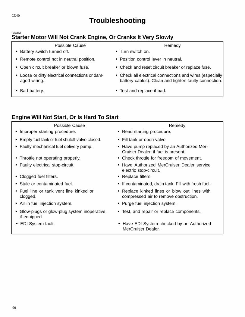
96
CD49
Troubleshooting
CD361
Starter Motor Will Not Crank Engine, Or Cranks It Very SlowlyPossible Cause Remedy
• Battery switch turned off. • Turn switch on.
• Remote control not in neutral position. • Position control lever in neutral.
• Open circuit breaker or blown fuse. • Check and reset circuit breaker or replace fuse.
• Loose or dirty electrical connections or dam-aged wiring.
• Check all electrical connections and wires (especiallybattery cables). Clean and tighten faulty connection.
• Bad battery. • Test and replace if bad.
Engine Will Not Start, Or Is Hard To StartPossible Cause Remedy
• Improper starting procedure. • Read starting procedure.
• Empty fuel tank or fuel shutoff valve closed. • Fill tank or open valve.
• Faulty mechanical fuel delivery pump. • Have pump replaced by an Authorized Mer-Cruiser Dealer, if fuel is present.
• Throttle not operating properly. • Check throttle for freedom of movement.
• Faulty electrical stop-circuit. • Have Authorized MerCruiser Dealer serviceelectric stop-circuit.
• Clogged fuel filters. • Replace filters.
• Stale or contaminated fuel. • If contaminated, drain tank. Fill with fresh fuel.
• Fuel line or tank vent line kinked orclogged.
• Replace kinked lines or blow out lines withcompressed air to remove obstruction.
• Air in fuel injection system. • Purge fuel injection system.
• Glow-plugs or glow-plug system inoperative,if equipped.
• Test, and repair or replace components.
• EDI System fault. • Have EDI System checked by an AuthorizedMerCruiser Dealer.

97
Engine Runs Rough, Misses And/Or BackfiresPossible Cause Remedy
• Throttle not operating properly. • Check throttle linkages for binding or an obstruction.
• Idle speed too low. • Check idle speed and adjust, if necessary.
• Clogged fuel or air filters. • Replace filters.
• Stale or contaminated fuel. • If contaminated, drain tank. Fill with fresh fuel.
• Kinked or clogged fuel line or fuel tankvent line.
• Replace kinked line or blow out line with com-pressed air to remove obstruction.
• Air in fuel injection system. • Purge fuel injection system.
• EDI System fault. • Have EDI System checked by an AuthorizedMerCruiser Dealer.
Poor PerformancePossible Cause Remedy
• Throttle not fully open. • Inspect throttle cable and linkages for operation.
• Damaged or improper propeller. • Replace.
• Excessive bilge water. • Drain and check for cause of entry.
• Boat overloaded or load improperly dis-tributed.
• Reduce load or redistribute load more evenly.
• Boat bottom fouled or damaged. • Clean or repair as necessary.
• EDI System fault. • Have EDI System checked by an AuthorizedMerCruiser Dealer.

98
Excessive Engine TemperaturePossible Cause Remedy
• Seacock closed, if equipped. • Open.
• Drive belt loose or in poor condition. • Replace and/or adjust belt.
• Seawater pickups obstructed. • Remove obstruction.
• Faulty thermostat. • Replace.
• Coolant level low in closed coolingsection.
• Check for cause of low coolant level and repair.Fill system with proper coolant solution.
• Heat exchanger cores plugged withforeign material.
• Clean seawater side of water/waterheat exchanger, and seawater strainer.
• Loss of pressure in closed coolingsection.
• Check for leaks. Clean, inspect and test pres-sure cap.
• Closed cooling section dirty. • Clean and flush.
• Faulty seawater pickup pump. • Repair.
• Seawater discharge restricted or plugged. • Clean exhaust elbow.
• Seawater inlet hose kinked (restricted). • Position hose to prevent kinking (restriction).
• Use of improperly designed hose on inlet sideof seawater pump allowing it to collapse.
• Replace hose with wire reinforced design.
Insufficient Engine TemperaturePossible Cause Remedy
• Faulty thermostats. • Replace.

99
Low Engine Oil PressurePossible Cause Remedy
• Insufficient oil in crankcase. • Check and add oil.
• Excessive oil in crankcase (causing it tobecome aerated).
• Check and remove required amount of oil.Check for cause of excessive oil (improperfilling, bad fuel pump, etc.).
• Diluted or improper viscosity oil. • Change oil and oil filter, using correct gradeand viscosity oil. Determine cause for dilution(excessive idling, faulty fuel pump, etc.).
• Faulty senders. • Have system checked by an AuthorizedMerCruiser Dealer.
Battery Will Not Come Up On ChargePossible Cause Remedy
• Excessive current draw from battery. • Turn off non-essential accessories.
• Loose or dirty electrical connections ordamaged wiring.
• Check all associated electrical connections andwires (especially battery cables). Clean and tight-en faulty connections. Repair or replace damagedwiring.
• Alternator drive belt loose or in poor condition. • Replace and/or adjust.
• Unacceptable battery condition. • Test battery.
Remote Control Operates Hard, Binds, Has Excessive Free-play Or Makes Un-usual Sounds
Possible Cause Remedy• Insufficient lubrication on shift and throttle
linkage fasteners.• Lubricate.
• Loose or missing shift and throttle linkagefasteners.
• Check all linkages. If any are loose or missing, seeAuthorized MerCruiser Dealer immediately.
• Obstruction in shift or throttle linkages. • Remove obstruction.
• Shift or throttle cable kinked. • Straighten cable, or have dealer replacecable if damaged beyond repair.
• Vacuum leak at shift cylinder, hose or fittingsof Power Shift Assembly, if equipped.
• Repair cut, pinched, or kinked hose or faultyshift cylinder.
• Improper shift cable adjustment. • See Authorized MerCruiser Dealer immedi-ately for shift cable adjustment.

EXTRA HELP
100
CA461
Owner Service AssistanceLocal Repair ServiceAlways return your MerCruiser powered boat to your local Authorized Dealer, should the need for service arise.Only he has the factory trained mechanics, knowledge, special tools and equipment and the genuine Quicksilverparts and accessories* to properly service your engine should the need occur. He knows your engine best.
* Quicksilver parts and accessories are engineered and built by Mercury Marine, specifically for MercuryMerCruiser sterndrives and inboards.
Service Away From HomeIf you are away from your local dealer and the need arises for service, contact the nearest Authorized Dealer.Refer to the Yellow Pages of the telephone directory. If, for any reason, you cannot obtain service, contact thenearest Regional Service Center. Outside the United States and Canada, contact the nearest Marine PowerInternational Service Center.
Parts And Accessories InquiriesAll inquiries concerning Quicksilver replacement parts and accessories should be directed to your localAuthorized Dealer. The dealer has the necessary information to order parts and accessories for you should henot have them in stock. Only Authorized Dealers can purchase genuine Quicksilver parts and accessories fromthe factory. Mercury Marine does not sell to unauthorized dealers or retail customers. When inquiring on partsand accessories, the dealer requires the motor model and serial number(s) to order the correct parts.
CB577
Resolving A ProblemSatisfaction with your MerCruiser product is very important to your dealer and to us. If you ever have a problem,question or concern about your power package, contact your dealer or any Authorized MerCruiser Dealership.If additional assistance is required, take these steps.
1 Talk with the dealership’s sales manager or service manager. If this has already beendone, then contact the owner of the dealership.
2 Should you have a question, concern or problem that cannot be resolved by your deal-ership, please contact Mercury Marine Service Office for assistance. Mercury Marine willwork with you and your dealership to resolve all problems.
The following information will be needed by the service office:
• Your name and address
• Daytime telephone number
• Model and serial number for your power package
• The name and address of your dealership
• Nature of problem
Mercury Marine Service Offices are listed on the next page.

101
CA785
Mercury Marine Service OfficesFor assistance, call, fax, or write. Please include your daytime telephone number with mail and faxcorrespondence.
Telephone FaxMail
United States
(405) 743-6566 (405) 743-6570MerCruiser3003 N. Perkins Rd.Stillwater, OK 74075
Canada
(905) 567-MERC (6372) (905) 567-8515Mercury Marine Ltd.2395 Meadowpine Blvd.Mississauga, OntarioCanada L5N 7W6
Australia, Pacific
(61) (3) 791-5822 (61) (3) 793-5880Mercury Marine Australia132-140 Frankston RoadDandenong,Victoria 3164Australia
Europe, Middle East, Africa
(32) (87) 32 • 32 • 11 (32) (87) 31 • 19 • 65Marine Power - Europe, Inc.Parc Industriel de Petit-RechainB-4800 VerviersBelgium
Mexico, Central America, South America, Caribbean
(305) 385-9585 (305) 385-5507Mercury Marine - Latin America & Caribbean9010 S.W. 137th Ave.Suite 226Miami, FL 33186 U.S.A.
Japan
(81) 543/34-2500 (81) 543/34-2022Mercury Marine - JapanNo. 27-2 Muramatsu Chisaki-ShindenShimizu CityShizuoka PrefectureJapan 424
Asia, Singapore
5466160 5467789Mercury Marine Singapore72 Loyang WaySingapore 508762

102
CA463
Customer Service Literature
English LanguageEnglish language publications are available from:
Attn: Publications DepartmentMercury Marine
W6250 West Pioneer RoadP.O. Box 1939
Fond du Lac, WI 54936-1939
Outside the United States and Canada, contact the nearest Mercury Marine or Marine PowerInternational Service Center for further information.
When ordering be sure to:
1. List your product, model, year and serial number(s).
2. Check the literature and quantities you want.
3. Enclose full remittance in check or money order (NO C.O.D.’s).
CA781
Other LanguagesTo obtain an Operation, Maintenance and Warranty Manual in another language, contact the nearest MercuryMarine or Marine Power International Service Center for information. A list of part numbers for other languagesis provided with your power package.
caa781
Andre sprogKontakt det nærmeste Mercury Marine eller Marine Power International servicecenter for oplysninger om hvor-dan du kan anskaffe en Betjenings– og vedligeholdelsesmanual på et andet sprog. En liste med reservedels-numre for andre sprog leveres sammen med din power–pakke.cab781
Andere talenVoor het verkrijgen van een Handleiding voor gebruik en onderhoud in andere talen dient u contact op te nemenmet het dichtstbijzijnde internationale servicecentrum van Mercury Marine of Marine Power voor informatie hier-over. Een lijst met onderdeelnummers voor andere talen wordt bij uw motorinstallatie geleverd.cac781
Muut kieletSaadaksesi Käyttö– ja huolto–ohjekirjoja muilla kielillä, ota yhteys lähimpään Mercury Marine tai Marine PowerInternational huoltokeskukseen, josta saat lähempiä tietoja. Moottorisi mukana seuraa monikielinen varaosa-numeroluettelo.
103
cad781
Autres languesPour obtenir un Manuel d’utilisation et d’entretien dans une autre langue, contactez le centre de service après–vente international Mercury Marine ou Marine Power le plus proche pour toute information. Une liste des numé-ros de pièces en d’autres langues accompagne votre bloc–moteur.cae781
Andere SprachenUm eine Betriebs– und Wartungsanleitung in einer anderen Sprache zu erhalten, wenden Sie sich an dasnächste Mercury Marine oder Marine Power International Service Center. Eine Liste mit Teilenummern fürFremdsprachen ist im Lieferumfang Ihres Motors enthalten.caf781
Altre linguePer ottenere il manuale di funzionamento e manutenzione in altra lingua, contattate il centro assistenza interna-zionale Mercury Marine o Marine Power più vicino. In dotazione con il gruppo motore, viene fornito l’elenco deicodici prodotto dei componenti venduti all’estero.cag781
Andre språkYtterligere informasjon om bruks– og vedlikeholdshåndbok på andre språk kan fås ved henvendelse tilnærmeste internasjonale servicecenter for Mercury Marine eller Marine Power. En liste over delenumre forandre språk følger med aggregatet.cah781
Outros IdiomasPara obter um Manual de Operação e Manutenção em outro idioma, contate o Centro de Serviço Internacionalde “Marine Power” (Potência Marinha) ou a Mercury Marine mais próxima para obter informações. Uma listade números de referência para outros idiomas é fornecida com o seu pacote de propulsão.caj781
Otros idiomasPara obtener un Manual de operación y mantenimiento en otro idioma, póngase en contacto con el centro deservicio más cercano de Mercury Marine o Marine Power International para recibir información. Con su conjuntomotriz se entrega una lista de los números de pieza para los otros idiomas.cak781
Andra språkFör att få Instruktions– och underhållsböcker på andra språk, kontakta närmaste Mercury Marine eller MarinePower International servicecenter, som kan ge ytterligare information. En förteckning över artikelnummer på an-dra språk medföljer ditt kraftpaket.CAm781
����� ���������� �� �������� ��� ����ρ���� ������ρ���� ��� ����ρ��� � ���� ����, ����������� �� ���������ρ� ������� ����ρ� ��ρ��� ��� Mercury Marine ��� Marine Power ��� ���ρ� �ρ���. !� ������ ��"���� �����"���� ��# ���� �������� �ρ����� ��ρ�������� ��� ����� �����.

104
CA752
Ordering LiteratureBefore ordering literature, please have the following information about your power package available:
Model __________ Horsepower__________Serial Number_____________ Year_______
United States and CanadaFor information on additional literature that is available for your particular MerCruiser power package and howto order that literature contact your nearest dealer or contact:
Mercury Marine
Telephone Fax Mail
(920) 929-5110 (920) 929-4894
Mercury MarineAttn: Publications DepartmentP.O. Box 1939Fond du Lac, WI 54936-1939
Outside The United States and CanadaContact your nearest dealer or Marine Power Service Center for information on additional literature that isavailable for your particular MerCruiser power package and how to order that literature.
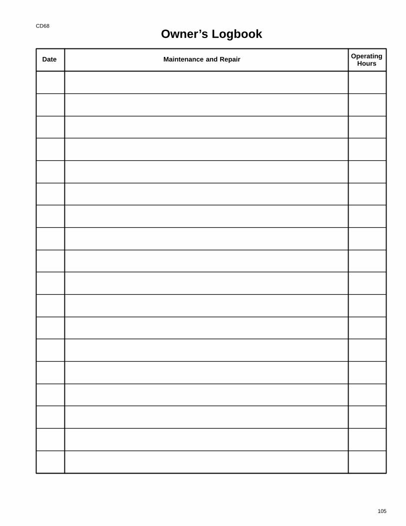
105
CD68
Owner’s Logbook
Date Maintenance and Repair OperatingHours

106
CD68
Owner’s Logbook
Date Maintenance and Repair OperatingHours

107
CD68
Owner’s Logbook
Date Maintenance and Repair OperatingHours

75308
108


