8508A Maximizing your reference multimeter, minimizing measurement uncertainties.pdf
12
Application Note Precision multimeter architecture In principle, the architecture of a reference multimeter is no different to that of a simple handheld. A block diagram is shown in figure 1. The key element is the analog to digital converter (adc), defining the basic capability to take an electrical signal and provide a digital (numeric) representation. Noise performance, stability, linearity, scale length, resolution, and speed vary tremendously from one instrument design to another. Reference metrology grade multimeters use an integrating adc where the input signal is effectively compared to an internal reference through charge balance in an integrator circuit. Up to 8.5 digits resolution can be achieved with linearity better than 0.1 ppm of full scale over a scale length of 2 x 10 8 counts. For dc voltage measurements the input signals are scaled by a combination of attenuators and low noise amplifiers in the dc pre-amp before being presented to the adc for conversion. A low pass filter at the dc pre-amp output, which the user can enable or disable, provides means to remove unwanted ac signals that may be present on the input. Maximizing your reference multimeter, minimizing measurement uncertainties From the Fluke Digital Library @ www.fluke.com/library Introduction Modern precision digital multimeters are sophisticated measuring instruments offering more than just the ability to measure voltage, current and resistance. More recently, a new type of precision multimeter, the Fluke 8508A Reference Multimeter, has been developed with the accuracy and stability of metrology grade instruments approaching measurement levels available from the standards used to calibrate them. Such high performance allows these multimeters to be used in place of many traditional laboratory instruments such as Kelvin-Varley dividers, null detectors, resistance bridges and even PRT (Platinum Resistance Thermometer) calibrators. Not only do metrology grade multimeters provide sufficient precision, they also bring a significant improvement in usability and throughput compared to traditional techniques – the latter being of great importance in today’s economic climate where calibration laboratories of every type are challenged to meet technical and business objectives alike. Instrumentation designers pay careful attention to maxi- mizing the functionality of the instruments, while at the same time ensure ease of use. However, these sophisticated instruments offering compre- hensive capability can appear complex to users. This application note sets out to simplify and explain how these various Fluke 8508A Reference Multimeter features can be used to maximize your lab’s efficiency.
-
Upload
nicole-floyd -
Category
Documents
-
view
44 -
download
3
description
maximaizing multuimeter uncertainties
Transcript of 8508A Maximizing your reference multimeter, minimizing measurement uncertainties.pdf

Application Note
Precision multimeterarchitectureIn principle, the architecture ofa reference multimeter is nodifferent to that of a simplehandheld. A block diagram isshown in figure 1. The keyelement is the analog to digitalconverter (adc), defining thebasic capability to take anelectrical signal and provide adigital (numeric) representation.Noise performance, stability,linearity, scale length, resolution,and speed vary tremendouslyfrom one instrument design toanother. Reference metrologygrade multimeters use an integrating adc where the
input signal is effectively compared to an internal referencethrough charge balance in anintegrator circuit. Up to 8.5digits resolution can be achievedwith linearity better than 0.1 ppmof full scale over a scale lengthof 2 x 10 8 counts. For dcvoltage measurements theinput signals are scaled by acombination of attenuators andlow noise amplifiers in the dcpre-amp before being presentedto the adc for conversion. A lowpass filter at the dc pre-ampoutput, which the user canenable or disable, providesmeans to remove unwanted acsignals that may be present onthe input.
Maximizing your reference multimeter,minimizing measurement uncertainties
From the Fluke Digital Library @ www.fluke.com/library
IntroductionModern precision digital multimeters are sophisticatedmeasuring instruments offeringmore than just the ability tomeasure voltage, current andresistance. More recently, anew type of precision multimeter,the Fluke 8508A ReferenceMultimeter, has been developedwith the accuracy and stabilityof metrology grade instrumentsapproaching measurementlevels available from the standards used to calibratethem. Such high performanceallows these multimeters to beused in place of many traditionallaboratory instruments such asKelvin-Varley dividers, nulldetectors, resistance bridgesand even PRT (PlatinumResistance Thermometer) calibrators. Not only do metrologygrade multimeters provide sufficient precision, they alsobring a significant improvementin usability and throughputcompared to traditional techniques – the latter being ofgreat importance in today’seconomic climate where calibration laboratories of everytype are challenged to meettechnical and business objectivesalike. Instrumentation designerspay careful attention to maxi-mizing the functionality of theinstruments, while at the sametime ensure ease of use.However, these sophisticatedinstruments offering compre-hensive capability can appearcomplex to users. This applicationnote sets out to simplify andexplain how these variousFluke 8508A ReferenceMultimeter features can beused to maximize your lab’sefficiency.

For ac voltage measurement,another signal path, also withsignal scaling, uses an rms todc converter to generate asignal representing the rmsvalue of the input, which inturn is measured by the adc. Toperform current measurementsthe current converter circuitincorporates current shunts thatproduce a voltage proportionalto the current input for measure-ment by either the dc or acvoltage sub-systems. Byemploying appropriate designtechniques, the input burdenvoltage that the multimeterpresents at its input terminalswhen measuring current canbe essentially isolated from thevoltage developed across theinternal current shunts, reducingthe disturbance (burden voltage)that it presents to the source ofcurrent being measured.Resistance measurement capa-bility is provided by an internalcurrent source, generating arange of stable constant currents,that, together with the variousvoltage ranges, allow resistanceto be measured by the simpleapplication of Ohms law. In thecase of the new 8508AReference Multimeter, rangesare extended from 2 Ω to 20 GΩfull scale. The input switchingdesign allows the referencemultimeter to have two sets ofinput terminals, one on theinstrument front panel and oneon the instrument rear panel.Both sets of terminals are specified to full 1000 V rmsrating. With two channels,ratiometric measurements canbe performed easily in both thevoltage and resistance functions.
ADC operation -Choosing the appropriateconfiguration for themeasurementThe multi-slope integrating adcis capable of extremely highresolution with linearity betterthan 0.1 ppm of full scale.However, high resolution, canonly be achieved at relativelylong integration times. In addition to trading off conversionspeed and resolution, the integration time has a directimpact on noise rejection. Theintegration itself effectivelyaverages any ac or noisecontent in the signal beingmeasured, reducing variation inthe displayed reading. It canalso be used to reject unwantedline frequency signals presenton the input being converted.These unwanted signals effectively appearing in serieswith the input are commonlyknown as series mode noise. Ifthe integration time is equal toan exact multiple of the lineperiod, the unwanted line frequency signal integrates outto zero. The user is able toselect the resolution and, in the8508A, can also choose betweena ‘normal’ and ‘fast’ adc mode,thereby effectively determiningthe integration time. Becausethe adc integration time isrelated to the power line frequency, the user must ensurethe reference multimeter is configured correctly for the linefrequency of the power supplyto which it is connected. This isnormally set during manufacture,but can also be set by the user.
In the dc voltage function the5.5 digit ‘fast’ mode has an integration time of 3.3 ms at 50 Hz and 60 Hz line operation.For all the other combinationsof resolution and adc normal/fast selection, the integrationtime is a multiple of power lineperiod. Provided the user correctly configures the referencemultimeter for line frequencythe adc will provide rejection ofline related signal pickup in allmodes except 5.5 digit ‘fast’.Up to 80 dB of rejection at line frequency multiples is typicallyachieved. Failure to set thecorrect line frequency willresult in excessively noisyreadings when series mode linepickup is present.
Choosing a higher resolutionmode will effectively meanchoosing a longer integrationtime, and the signal will be‘averaged’ within the adc integrator for longer. In additionto the higher resolution, theresult is lower reading toreading runaround (noise) anda lower effective bandwidth. Atthe higher resolutions multipleadc cycles are digitally averagedto provide a single displayedreading. The user can alsoemploy the reference multi-meter’s math modes to digitallyaverage readings, allowingflexibility in the trade offbetween effective noise band-width and measurement time.Choice of most appropriatemode will depend on the appli-cation, required resolution andsignal characteristics. For mostcalibration applications the 7.5digit ‘fast’mode is appropriate, producing readings with a1280 ms conversion time at 50 Hz line (1067 ms at 60 Hz).It should be noted that the effective read rate, with thereference multimeter freerunning in internal triggermode, may not be as fast asexpected, especially when considering the conversiontime alone. This is because theadc conversions are triggeredby an internal clock at approximately 2 Hz.
Fig. 1 Simplified DMM block diagram
2 Fluke Corporation Maximizing your reference multimeter, minimizing measurement uncertainties

Fig. 2 The basic arrangement for comparing two standards at the 10 V level
Achieving a faster read raterequires use of an externalhardware trigger signal or triggering from the IEEE488remote interface. This is equallyapplicable to measurementsmade in the resistance function,which utilizes the dc voltagemeasurement sub-system.
Practical dc applicationsTypical metrology applicationsinclude comparing voltagestandards and voltage ratiomeasurements. For voltagestandards, the comparison willtypically be of two or morevoltages at nominally the samelevel e.g. comparing two ormore 1 V standards with amicrovoltmeter or null detector.Provided that the meter is sensitive enough and the difference between the references is less than 10 µV,this simple detector can givevery good results and is able toresolve differences as small as200 nV (0.2 ppm of 1 V).However, if the reference standards have a large voltagespread the differences could beas large as a millivolt. A typicalmicrovoltmeter under theseconditions would only resolve20 µV on its 1 mV range, dueto the fundamental limitationsof scale length and resolution.A reference multimeter on its200 mV range can resolve 10 nV. Subject to noise limitations, it could measuretwo standards that were well
over 100 mV apart and stillresolve 10 nV. Electronic,Zener-based references arenow widely used and oftenhave outputs at the 10 V, 1 Vand 1.018 V levels. Comparisonbetween the different voltageoutputs requires knowledge ofthe voltage ratio. Traditionally,high-precision voltage dividerswould be used for this task, aknown voltage at the 10 Vlevel would be divided by aknown ratio through the (calibrated) divider and compared at the 1 V or 1.018 Vlevel using a microvoltmeter.The divider would have to beknown for all the requiredratios and would be adjusted tonull the microvoltmeter. Thereference multimeter canreplace these instruments andsimplify the measurement.Figure 2 shows the basicarrangement for comparing twostandards at the 10 V level –the connections would be verysimilar for 1 V or 1.018 V. Notethat the arrangement is verysimilar to that described forcomparing dc standards with amicrovoltmeter except that nowthe reference multimeter(rather than a microvoltmeter)can handle large differencesbetween the two deviceswithout sacrificing resolution.There are no significant problemswith this measurement providedthat the reference multimeterisolation to ground does notload the output of either voltage
reference and that a preliminaryzero operation is performed toremove any residual offsets inthe multimeter and its connectingleads. The configuration shownis effectively a potentiometricor differential measurement.The reference multimeter isconfigured to measure the difference between the twovoltage references.
Ratio mode and rearinputsThe 8508A ReferenceMultimeter has two input channelsthat may be switched automat-ically to perform a ratio measurement. In ratio mode,the 8508A displays the ratio ofthe inputs in the form F-R(front minus rear), or F/R (frontas a percentage of the rear), or(F-R)/R (the difference as apercentage of the rear). Themost commonly used of theseratios is F/R (i.e. the front as apercentage of the rear). In thismode with, for example, 10 Vconnected to rear channel (reference) and 1 V connectedto the front channel, the displaywould show +10.000 000 %.This is the ratio of the unknown1 V to the known 10 V reference.Note that the reference multi-meter is measuring the wholevoltage for each channel and isconfigured to a single (20 V)range. The only error contri-butions to this measurementare the uncertainty of the 10 Vreference standard, the noiseand differential linearity of thereference multimeter and thenoise of the UUT 1 V standard.Typical noise of the referencemultimeter is <50 nV pk/pk(7½ normal & 8½ fast adcmodes) and differential linearityin 8½ digit mode is better than0.1 ppm of full scale over a10:1 ratio. These figures aresimilar to that which might beobtained by a skilled metrologistwith a freshly calibrated voltagedivider and microvoltmeter.
Fluke Corporation Maximizing your reference multimeter, minimizing measurement uncertainties 3

However, linearity can be verified in the following way.Figure 4 shows the circuit configuration for resistancemeasurement used in a referencemultimeter. The resistanceoption is primarily a range ofselectable constant currents. A constant current generatorforces a current Ix to flowthrough the test resistor Rx. Atrue constant current sourcewill generate a current independently of the voltagedeveloped across its terminals,in this case designated Input Hiand Input Lo.
Fig. 3 Voltage ratio measurement
Fig. 4 Reference multimeter ohms converter
The reference multimeter canmake this measurement contin-uously and its linearity doesnot change significantly withtime, so setup costs are lowerand the measurements areautomated, taking less time.Figure 3 shows how the refer-ence multimeter can be used tomeasure the whole voltage ofeach reference by using identicalmultiple input channels in theratio mode. Confirmation of thereference multimeter’s linearitybeyond the 0.1 ppm level isdifficult under normal circum-stances. However, severalinstruments have now beenevaluated against 10 V Josephsonarrays. In this measurement,the Josephson system can bemade to generate a series ofvoltages between 1 V and 10 Vwith uncertainties at least anorder of magnitude better thanmost precision or reference multimeter’s linearity.
Resistance applicationsAnother very useful applicationof the reference multimeter isin resistance measurements. An8½ digit reference multimeterhas virtually the same linearityon its resistance function as fordc voltage, except, in this case,there are no resistance standardsaccurate enough to be able toprove resistance linearity in aconventional sense. One of theproblems of trying to measureresistance linearity directly isthe uncertainty of the individualresistor values. For example,measuring linearity on the 20 kΩrange of an 8½ digit referencemultimeter with a maximumindication of 19.000 000 0 kΩwould require several differentresistance standards. Assumingthat measurements were to bemade at a minimum of fiveevenly spaced points through-out the range, e.g. at zero, 5 kΩ,10 kΩ, 15 kΩ, and 19.9 kΩ,the difficulties in finding suitablestandards soon become obvious.Typically, resistance standardswill be available at the normal
decade values of 10 Ω (25 Ωmay be available), 100 Ω, 1 kΩ,10 kΩ, etc. and so do notprovide even coveragethroughout the range. Whenone considers that some DMMshave resistance linearity speci-fications of better than 0.3 ppm,and that individual resistancestandards may have uncertaintiesof 1 ppm or more, test methodsusing separate resistors ordecade boxes will be inadequate.For this reason, resistance linearity is not usually measuredduring routine calibrations ofreference multimeters.
4 Fluke Corporation Maximizing your reference multimeter, minimizing measurement uncertainties

Changes in ambient tempera-ture due to draughts, airflowwithin a room or through aninstrument or even variationsin a room’s air-conditioningtemperature can lead to offsetsthat are constantly changing.
Finally there are offsetswhich occur as a result ofdirect heating of the shuntresistor by the energizingcurrent. Where large currentsare involved, this can also giverise to thermo-electric effects(Peltier and Seebeck) in externalconnections too. These dynamicthermal offsets only occurwhen the current is flowing,but because of their longthermal time-constant, can bemeasured. Traditional resistancebridge measurements use aspecific process to isolateresistance from other unwantedparasitics i.e. voltage offsets. Atypical arrangement would beto place the known and un-known resistors in series andpass a current through them. A voltage ratio measurementwould then be made of thevoltages developed across thepotential terminals of eachresistor. The current supplywould then be reversed andthe measurement repeated. Thecurrent reversal will canceleffects of the voltage offsetsbecause in one polarity theywould add to the measuredvoltage and in the reversepolarity would subtract from it.The average voltage ratio fromthe forward and reverse currentswill remove the offsets.
It therefore follows that if aknown resistance is applied tothe reference multimeter andthe display value noted, theinsertion of an additionalresistance in series with theInput Hi lead should not signifi-cantly affect the multimeter’sreading. This will confirm thatthe current source can deliverthe same current through arange of resistance values. If itcan also be confirmed that thevoltage range used for theresistance measurement is alsolinear, there is then a technicallysound way of confirming goodresistance linearity without theneed for a resistance linearitystandard. Note that the seriesresistance does not need to bea precision resistor – it couldbe a low-noise potentiometer.
True Ohms – Avoidingthermal emf errorsA typical mistake is to confusethe four-wire and True Ohmsresistance measurement techniques. However, the two principles are quite differentand are used to avoid resistancemeasurement errors. It is customary in a metrologyapplication to employ four-wiresensing techniques for measuringlower value resistors so thatseries lead resistance errors areeliminated. However, this tech-nique does not take into accountthe effects of voltage offsets.
Voltage offsets are causedby junctions of dissimilarmetals at different temperatureswithin the voltage measuringcircuit. Typical sources mightbe within the resistor itself, orconnecting leads and terminals.This is why temperature uniformity within a calibrationlaboratory is important. Therewill also be voltage offsetswithin the reference multimeteritself. A simple zero operation(a mathematical subtraction)before the measurement commences will remove all ofthese ‘static’ offsets.
These voltage offsets can alsobecome ‘dynamic’ in their nature.
Unfortunately, this reversalof current technique could onlybe found in expensive resistancebridges. Previous multimeterdesigns have attempted toovercome this problem usingeither True Ohms or OffsetCompensated Ohms techniques.These methods essentiallyswitch off the current sourceand take an additional voltagereading at zero current, thensubtract this result digitallyfrom the ‘current on’ voltagereading, thereby eliminatingthe effect of unwanted offsetsin the measurement path.However, this technique suffersthe disadvantage that themeasurement current switchesat the read rate, modulating thepower dissipation and temp-erature of the resistor undertest. This effect can lead to significant errors when measuring certain types ofresistors, particularly low values,and resistors that have largetemperature and powerdependencies – an examplebeing platinum resistance thermometer elements.
However, the Fluke 8508AReference Multimeter hasenhanced resistance measure-ment capabilities and can nowcompensate automatically forany static or dynamic thermalemfs. The current reversal TrueOhms technique has beendeveloped and implemented,illustrated in figure 5. In thiscase, the current source iscapable of being reversed.
With forward current:
V1 = I x R + Vth
With reverse current:
V2 = -(-I x R + Vth)
Averaging V1 and V2:
= 0.5(2 x I x R + Vth - Vth) = I x R
Sense path reversal ensures V1 and V2 have same polarity for adc conversion. Note thatany offset in the PD measurement path after the reversal switching is not cancelled but isremoved with zero calibration and input zero operations.
Fig. 5 Current reversal True Ohms
Fluke Corporation Maximizing your reference multimeter, minimizing measurement uncertainties 5

The same number of adc cyclesoccur for each polarity, but thechange in emf between consecutive polarity reversals ismuch smaller so cancellation ismore effective.
Ohms guardAnother consideration when
measuring higher value resistances is the effect of parallel leakages in the meas-urement circuit. Such leakageswill divert some current awayfrom the resistor being measuredand cause an error in themeasurement. A reference multimeter’s ohms guard caneffectively remove the effects ofleakage provided that a suitableconnection for the guard isavailable.
The Fluke 8508A ReferenceMultimeter’s resistance functionhas an ‘Ext Grd’ option thatcan be selected to make theGuard terminal function as Ω Guard. Figure 7 and 8 showsthe Fluke 8508A ReferenceMultimeter’s Ohms guard inuse. The Lo Follower will maintain Lo and AnalogCommon (0 V) at the samepotential by forcing morecurrent through Rx and Ra untilLo is at 0 V (Ib=0). The cali-brated current Ix will then beflowing through Rx. Note thatwhere the connection leadinsulation is suspect, runningInput Sense and Input Hi inone shield, and Input Senseand Input Lo in another, whileconnecting both shields toohms guard, will remove anyleakage between InputHi/Sense Hi and Input Lo/SenseLo (See Figure 8).
Fig. 6a Current reversal after each reading
Fig. 7 Ohms guard connections
Fig. 6b Current reversal after each adc cycle
6 Fluke Corporation Maximizing your reference multimeter, minimizing measurement uncertainties
Each reading consists of twomeasurements, taken auto-matically under the control ofthe multimeter’s processor. Thefirst reading is taken with thecurrent in the forward direction,the second with the current inthe reverse direction and thetwo measurements are averagedto provide the displayed result.The power dissipation in theresistance under test remainsconstant, as the current isnever switched to zero. Notonly is static thermal emf cancellation achieved, butchanging thermal emfs are alsocancelled.
As with the dc voltage function, when in the TrueOhms function the user is ableto select the resolution and adcmode, effectively controllingreading resolution and sample(integration) time. At the higherresolutions relatively longeffective integration timeswould limit the effectiveness ofthe True Ohms thermal emfcancellation, if those thermalemfs changed significantlyduring the integration time. Toavoid this situation at thehigher resolutions where multipleadc cycles are digitally averaged,the current is reversed severaltimes during the readingsequence, rather than just once.Figure 6a shows four adccycles being averaged for areading in each polarity withcurrent reversal taking placeafter each reading. Figure 6bshows current reversal takingplace after each adc cycle.

Fig. 8 Ohms guard operation
Fig. 9 Resistance ratio
This is because the leakage is‘seen’ as a parallel resistancepath with a convenient tapping(the cable screens) for ohmsguard. Provided the currentleakage resistance path isgreater than 250 Ω, not onlywill the leakage current besourced from the Lo follower(as Ia), but any lead capacitancecharge current will also bedriven resulting in reduced settling times for high valueresistors.
Resistance transfers andratioThe Ratio function is availableon the Fluke 8508A’s Resistancefunction. Furthermore, ohmsguard is also available on thereference multimeter front andrear inputs and is used to eliminate lead leakages fromhigh resistance measurements.When combined with ratioswitching, very high accuracyautomated resistance transferscan be performed for both 1:1and 10:1 ratios. In either case,the reference multimeter willbe configured for the appropriateresolution (5½ to 8½ digits),adc speed, ohms sourcecurrent, analog/digital filter andratio mode for the particularresistor values concerned. The range selection will bechosen to accommodate thehigher of the two resistor values.For example, a 10 kΩ to 1 kΩratio will use the referencemultimeter’s 20 kΩ range – themultimeter’s excellent linearitywill ensure the maximumtransfer accuracy between thetwo values. Figure 9 shows thereference multimeter configuredvia the front and rear input terminals to compare tworesistance standards usingresistance ratio.
Fluke Corporation Maximizing your reference multimeter, minimizing measurement uncertainties 7
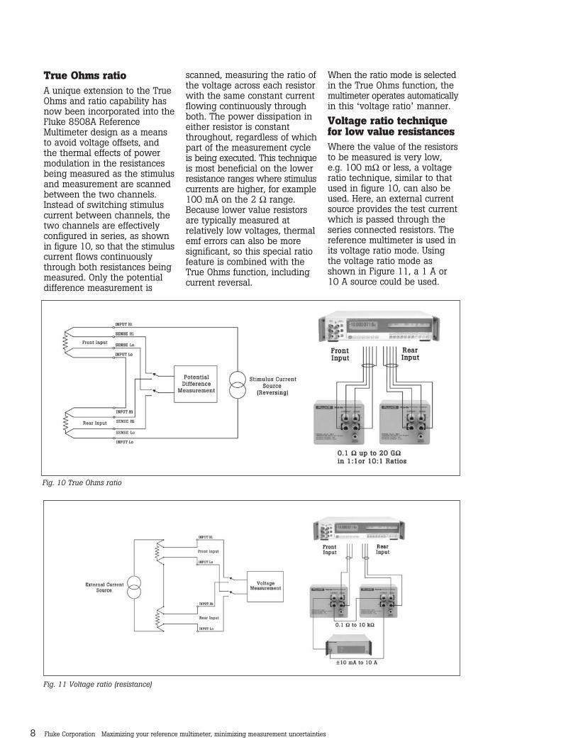
Fig. 10 True Ohms ratio
Fig. 11 Voltage ratio (resistance)
True Ohms ratioA unique extension to the TrueOhms and ratio capability hasnow been incorporated into theFluke 8508A ReferenceMultimeter design as a meansto avoid voltage offsets, andthe thermal effects of powermodulation in the resistancesbeing measured as the stimulusand measurement are scannedbetween the two channels.Instead of switching stimuluscurrent between channels, thetwo channels are effectivelyconfigured in series, as shownin figure 10, so that the stimuluscurrent flows continuouslythrough both resistances beingmeasured. Only the potentialdifference measurement is
scanned, measuring the ratio ofthe voltage across each resistorwith the same constant currentflowing continuously throughboth. The power dissipation ineither resistor is constantthroughout, regardless of whichpart of the measurement cycleis being executed. This techniqueis most beneficial on the lowerresistance ranges where stimuluscurrents are higher, for example100 mA on the 2 Ω range.Because lower value resistorsare typically measured at relatively low voltages, thermalemf errors can also be moresignificant, so this special ratiofeature is combined with theTrue Ohms function, includingcurrent reversal.
When the ratio mode is selectedin the True Ohms function, themultimeter operates automaticallyin this ‘voltage ratio’ manner.
Voltage ratio techniquefor low value resistancesWhere the value of the resistorsto be measured is very low,e.g. 100 mΩ or less, a voltageratio technique, similar to thatused in figure 10, can also beused. Here, an external currentsource provides the test currentwhich is passed through theseries connected resistors. Thereference multimeter is used inits voltage ratio mode. Usingthe voltage ratio mode asshown in Figure 11, a 1 A or10 A source could be used.
8 Fluke Corporation Maximizing your reference multimeter, minimizing measurement uncertainties
Dial # Step value Decademaximum
Reference multimeter range
Reference multimeter digits
Measurement resolution% of step ppm of kΩΩ
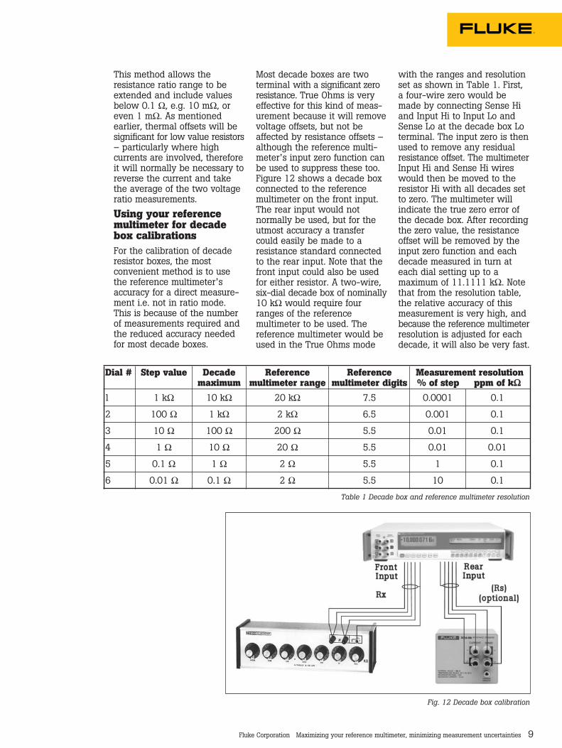
1 1 kΩ 10 kΩ 20 kΩ 7.5 0.0001 0.1
2 100 Ω 1 kΩ 2 kΩ 6.5 0.001 0.1
3 10 Ω 100 Ω 200 Ω 5.5 0.01 0.1
4 1 Ω 10 Ω 20 Ω 5.5 0.01 0.01
5 0.1 Ω 1 Ω 2 Ω 5.5 1 0.1
6 0.01 Ω 0.1 Ω 2 Ω 5.5 10 0.1
Fig. 12 Decade box calibration
Table 1 Decade box and reference multimeter resolution
This method allows the resistance ratio range to beextended and include valuesbelow 0.1 Ω, e.g. 10 mΩ, oreven 1 mΩ. As mentionedearlier, thermal offsets will besignificant for low value resistors– particularly where high currents are involved, thereforeit will normally be necessary toreverse the current and takethe average of the two voltageratio measurements.
Using your referencemultimeter for decadebox calibrationsFor the calibration of decaderesistor boxes, the most convenient method is to usethe reference multimeter’saccuracy for a direct measure-ment i.e. not in ratio mode.This is because of the numberof measurements required andthe reduced accuracy neededfor most decade boxes.
Most decade boxes are two terminal with a significant zeroresistance. True Ohms is veryeffective for this kind of meas-urement because it will removevoltage offsets, but not beaffected by resistance offsets –although the reference multi-meter’s input zero function canbe used to suppress these too. Figure 12 shows a decade boxconnected to the referencemultimeter on the front input.The rear input would not normally be used, but for theutmost accuracy a transfercould easily be made to aresistance standard connectedto the rear input. Note that thefront input could also be usedfor either resistor. A two-wire,six-dial decade box of nominally10 kΩ would require fourranges of the reference multimeter to be used. The reference multimeter would beused in the True Ohms mode
with the ranges and resolutionset as shown in Table 1. First,a four-wire zero would bemade by connecting Sense Hiand Input Hi to Input Lo andSense Lo at the decade box Loterminal. The input zero is thenused to remove any residualresistance offset. The multimeterInput Hi and Sense Hi wireswould then be moved to theresistor Hi with all decades setto zero. The multimeter willindicate the true zero error ofthe decade box. After recordingthe zero value, the resistanceoffset will be removed by theinput zero function and eachdecade measured in turn ateach dial setting up to amaximum of 11.1111 kΩ. Notethat from the resolution table,the relative accuracy of thismeasurement is very high, andbecause the reference multimeterresolution is adjusted for eachdecade, it will also be very fast.
Fluke Corporation Maximizing your reference multimeter, minimizing measurement uncertainties 9

Fig. 13 Conventional DMM input ‘shunt’ configuration
Fig. 14 Ammeter input ‘virtual earth’ current configuration
High voltage resistancemeasurementsBy increasing the outputvoltage drive capability of theLo Follower in figure 8, theability of the system tomeasure high resistances canbe significantly improved, withranges up to 20 GΩ. In previousimplementations of this topologythe maximum voltage was 20 V,but the Fluke 8508A designincreases this to over 200 V.Therefore when using the8508A’s Hi voltage resistancefunction, extreme caution mustalways be taken, as voltageson the input terminals canpotentially reach well in excessof the nominal 200 Vdc.
This technique requires useof the higher voltage rangeswithin the dc voltage measure-ment sub-system (the 200 Vrange) with an input impedanceof approximately 10 MΩ.However, this relatively lowimpedance, in comparison withthe resistances to be measured(up to 20 GΩ), is not a problemas any input current taken bythe dc voltage measurementsub-system is simply suppliedby the Lo Follower output viathe Input Hi terminal, whichdoes not affect the stimuluscurrent provided by the currentsink via the Input Lo terminal.Measurement of high resistancesat higher voltages improvesnoise performance, reduces theimpact of leakages (becausethe stimulus current is higher)and allows evaluation of resistorvoltage coefficients by makingmeasurements of the sameresistor in both normal andhigh voltage resistance modes.
Low burden ‘Virtual Earth’current measurementtechniquesThe majority of multimeterinstrument designs, includingPrecision DMMs, utilize the‘shunt’ method of currentmeasurement, as illustrated infigure 13. Here, the inputcurrent is passed through ashunt resistor Rs and the
voltage developed across theshunt (Vs) is applied to themultimeter’s ac or dc measure-ment circuit. A multi-rangeinstrument uses different valuesof Rs for each range. Sufficientvoltage must be developed toensure adequate measurement,but this voltage also appears atthe current input terminals asthe burden voltage Vin.Developing a high burdenvoltage can disturb the conditionsin the circuit where the currentis being measured when theDMM is inserted to make themeasurement. Any externalstray capacitance presentbetween the input terminals(such as lead capacitance)effectively appears across theshunt, and is exposed to Vo. Forlower current ranges the relatively high impedancevalues of the shunts increase
10 Fluke Corporation Maximizing your reference multimeter, minimizing measurement uncertainties
the susceptibility to straycapacitance and can cause frequency response degradation.The design of a new generationreference mulitmeters hasaddressed these issues.
The Fluke 8508A uses a‘virtual earth’ current measure-ment technique (figure 14) onthe 200 µA, 2 mA and 20 mAranges. This method essentiallyminimizes the burdens previouslyassociated with the ‘shunt’method and significantlyreduces the input resistance.Here, the input current passesthrough the feedback resistor(Rs) of an inverting amplifier,and the voltage developed atits input (the virtual earth) iszero, effectively isolating theinput burden voltage from thevoltage developed across theshunt Rs.

The output voltage Vo is I x Rs,which can now be made suffi-ciently large for measurementby the voltage measuring circuits.The virtual earth current measurement topology bringsgreatest benefits for the lowercurrent ranges where the shuntresistance values are relativelyhigh. For the higher currentranges the ‘shunt’ topology canbe used successfully and isemployed in the Fluke 8508Afor 200 mA, 2A and 20 A ranges.
For the operator there aretwo main advantages of usinga current measurement with‘virtual earth’ input. Firstly, andas discussed above, with aninput resistance of virtuallyzero, current measurements arefar less invasive, disturbing theconditions less when the multimeter is inserted into thecircuit, because the voltagedeveloped across the multimetercurrent input is much less. Butsecondly, guarding arrangementsare also simplified. This isbecause there is less opportunityfor leakage errors to take place,as the voltage developed acrossthe multimeter input is muchlower. Leakage errors typicallybecome a problem when measuring ac currents at higherfrequencies due to stray capacitance in the cables usedto make connection to the multimeter.
Solving the problem ofself heating in current measurementsMost general-purpose multimetersof 3 or 4½ digit resolution canmeasure both ac and dc currentsup to 20 A at modest accuracylevels. The temperature coefficient characteristics of thecurrent shunts and the self-heating effects due to powerdissipation in the shunts limitlinearity and settling time performance, adversely affectingthe multimeter’s accuracy.Consequently, high currentranges are usually absent fromhigher precision multimeters.
Using state of the art techniques, Fluke designershave successfully overcomethese obstacles, allowingmetrologists to make practicalhigh current measurementsdirectly with the 8508AReference Multimeter. The Fluke8508A Reference Multimeterutilizes high accuracy currentshunts with extremely lowtemperature coefficients andminimal power dissipation.Careful design of surroundingcircuitry and thermal manage-ment has optimized settlingtime and linearity performanceconsistent with the requirementsfor metrology applications.
High current measurementsOne of the new features tocome out with the launch ofthe new generation referencemultimeter is that of highercurrent measurement on bothac and dc current ranges.Previously, all leading edgePrecision DMM’s could onlymeasure current to 2 A full-scale, which posed a realproblem for applications thatrequired current calibration of 2 A or more. For example, calibrating the ac or dc currentranges of a multi-product calibrator had always been atwo-stage affair. Typically,current ranges up to 2 A wouldhave been calibrated using anyprecision long-scale DMM asnormal. However, multi-productcalibrators like the Fluke5520A have ac and dc currentranges to 20 A and thereforecould not be calibrated by justa Precision DMM alone. Thishigher current 20 A rangewould require the use of a suitably calibrated currentshunt connected to the long-scale precision DMM, set to theappropriate voltage range atthe full-scale current passingthrough the shunt.
The 8508A ReferenceMultimeter can measure bothac and dc currents to 20 A full-scale thereby, eliminating theneed for external currentshunts and connection cables,and so making the process ofhigh current measurement a loteasier to prepare and perform.
Using the reference multimeter as a highaccuracy temperaturecalibration toolReference multimeters like theFluke 8508A can now offer themetrologist another string totheir high accuracy measure-ment bow. The highly accuratetemperature measurementfunction on the Fluke 8508Aallows the user to perform afurther two more calibrationfunctions. Firstly, when coupledto a PRT (Platinum ResistanceThermometer) device withknown characteristics, the reference multimeter can beused simply as a means to reada temperature being measuredby the PRT. This is useful whencalibrating temperature sourceslike dry wells. Secondly, thereference multimeter can alsobe used to calibrate PRT orSPRT (standard platinum resist-ance thermometer) probes. Andwith two inputs, comparisonsand transfer measurements aresimple.
Prior to making any temp-erature measurement, the PRTor SPRT’s coefficients and configuration must be enteredinto the reference multimeter.The Fluke 8508A ReferenceMultimeter can store up to 100probe settings, all of which canbe edited or deleted as required.It can also be set up for a 2, 3or 4-wire PRT or SPRT probesand for values of 25 Ω or 100 Ω.For high accuracy SPRT calib-ration applications the ITS-90sub ranges are supported, as tooare the Callendar van Duesenconversion algorithms for PRTprobes for all industrial applications.
Fluke Corporation Maximizing your reference multimeter, minimizing measurement uncertainties 11

Fluke Corporation Maximizing your reference multimeter, minimizing measurement uncertainties
Fluke. Keeping your worldup and running.
Fluke CorporationPO Box 9090, Everett, WA USA 98206
Fluke Europe B.V.PO Box 1186, 5602 BD Eindhoven, The Netherlands
For more information call:In the U.S.A. (800) 443-5853 or Fax (425) 446-5116In Europe/M-East/Africa (31 40) 2 675 200 or Fax (31 40) 2 675 222Canada (800)-36-FLUKE or Fax (905) 890-6866From other countries +1 (425) 446-5500 or Fax +1 (425) 446-5116Web access: http://www.fluke.com/©2003 Fluke Corporation. All rights reserved. Trademarks are the property of their respective owners.Printed in UK 4/2003 2090893 D-ENG-N Rev A, DS267
Having probes calibratedindependently from the reference multimeter providesusers the flexibility to use anyother probe of appropriateresistance with the referencemultimeter, and not just theprobe supplied. Measurement uncertainty is notsacrificed, as the route for temperature traceability throughthe established conversionalgorithms is based on resistancemeasurements at specific temperatures, and not a directtemperature measurement.Directly calibrating the 8508Atogether with a specific probewould not yield better temper-ature measurement uncertainties,but would mean a significantloss in flexibility when usingother probes.
An electrical and temperature metrologymeasurement in onesingle solutionThe reference multimeter hasmany benefits, particularly forusers with both electrical andtemperature calibrations toperform.
When used with an SPRT orPRT probe, the reference multi-meter’s PRT function is idealfor precision temperaturemeasurements and calibrations.The two-channel ratio capabilityavailable in the True Ohmsfunction can also be used tocompare PRT probes directly interms of their resistances.However, if measurement ofseveral PRT probes simultan-eously is required, then one ofthe many multi-channel precisionthermometry solutions offeredby Hart Scientific, a Flukecompany, would be ideally suited.
SummarySince the introduction of theFluke 8508A in June 2002, thereference multimeter is nowbeing seen as the naturalreplacement for many of thetraditional measurement methodscurrently used in electricalmetrology laboratories world-wide. Already, the Fluke 8508AReference Multimeter can befound in national standardslabs, commercial laboratoriesand even militaries around theworld. With greater accuracyand stability, versatility andease of use the reference multi-meter is now seen as the idealinvestment or long-scale DMMupgrade for any electricalmetrology based application orlaboratory. And with yet morefunctionality, the referencemultimeter is a much moreattractive and cost effectivealternative to the metrologist’sformer favorite – the precision,long-scale DMM.
Reference standard accuracy and stability, in onefunctionally versatile, easy to use solution
Fluke 8508A Reference Multimeter
The Fluke 8508A provides atemperature readout by meas-uring the resistance of the PRTor SPRT probe connected, andconverting the resistance valueto temperature. The multimeterwill auto-range between the200 Ω ‘Lo I’ Ohms range andthe 2 kΩ ‘Normal’ Ohms rangedepending on the resistancevalue obtained at the tempera-ture being measured. Currentreversal True Ohms is usedwith a stimulus current of 1 mA.The Fluke 8508A ReferenceMultimeters can also be set upto display one of three userselectable units of measure –degrees Centigrade, degreesFahrenheit or Kelvin, at up to8.5 digits resolution.
PRT probe calibrationdata and flexibilityThe Fluke 8508A ReferenceMultimeter can be suppliedwith an extended range SPRTor a secondary standard PRTprobe from Hart Scientific, aFluke company. Alternatively,these probes can be purchasedas Fluke 8508A accessories. Allprobes are supplied with adetailed certificate of calibrationcontaining the coefficientsneeded for the temperatureconversion algorithms, obtainedby calibration at low uncertaintyagainst Hart’s temperature andresistance standards. To usewith the Fluke 8508A, theprobe coefficients must first beentered into the reference multimeter, so that the resistanceto temperature conversionalgorithms can correctlyconvert the resistance valuesobtained for that particularprobe, into accurate temperaturereadings.
This is a fine example of bothFluke and Hart Scientificworking together to offer acomplete range of temperaturemeasurement solutions to meetthe needs of any such application.