8100 Mobile Device System - Spirent · (2G and 3G), UMTS Simulated Drive Test, and UMTS Functional...
54
8100 Mobile Device System Platform Manual
Transcript of 8100 Mobile Device System - Spirent · (2G and 3G), UMTS Simulated Drive Test, and UMTS Functional...

8100 Mobile Device System Platform Manual

Spirent 541 Industrial Way West Eatontown, NJ 07724 USA
Email: [email protected] Web: http://www.spirent.com
AMERICAS 1-800-SPIRENT • +1-818-676-2683 • [email protected] EUROPE AND THE MIDDLE EAST +44 (0) 1293 767979 • [email protected] ASIA AND THE PACIFIC +86-10-8518-2539 • [email protected]
This manual applies to 8100 Mobile Device Test System Version 4.10 or higher.
Page Part Number: 71-004904, Version A11
Copyright © 2012 Spirent. All Rights Reserved.
All of the company names and/or brand names and/or product names referred to in this document, in particular, the name “Spirent” and its logo device, are either registered trademarks or trademarks of Spirent plc and its subsidiaries, pending registration in accordance with relevant national laws. All other registered trademarks or trademarks are the property of their respective owners.
The information contained in this document is subject to change without notice and does not represent a commitment on the part of Spirent. The information in this document is believed to be accurate and reliable; however, Spirent assumes no responsibility or liability for any errors or inaccuracies that may appear in the document.

Table of Contents
1. Introduction ..................................................................................... 1
1.1. Purpose ............................................................................................. 1
1.2. Intended Audience ............................................................................. 1
1.3. Before You Get Started ....................................................................... 1
1.4. Accessing the Documentation ............................................................ 2
1.4.1. Accessing the Documentation from Windows Explorer .............................. 2
1.4.2. Accessing the Documentation from Test Manager .................................... 2
1.4.3. Accessing the Documentation from TestDrive ........................................... 3
1.4.4. Accessing LTE Documentation from the Desktop ....................................... 4
2. Associated Hardware ........................................................................ 5
2.1. 8100-A50 Platform ............................................................................. 5
2.2. 8100-A100 Platform ........................................................................... 6
2.3. 8100-A200 Platform ........................................................................... 7
2.4. 8100-A300 Platform ........................................................................... 8
2.5. 8100-A304 Platform ........................................................................... 9
2.6. 8100-A400 Platform ......................................................................... 10
2.7. 8100-A500 Platform ......................................................................... 11
2.8. 8100-A600 Platform ......................................................................... 12
2.9. 8100-A604 Platform ......................................................................... 13
2.10. 8100-A750 Platform ......................................................................... 14
2.11. 8100-B041 Platform ........................................................................ 15
2.12. 8100-B051 Platform ........................................................................ 16
2.13. 8100-B100 Platform ........................................................................ 17
2.14. 8100-B200 Platform ........................................................................ 18
2.15. 8100-B300 Platform ........................................................................ 19
2.16. 8100-B500 Platform ........................................................................ 20
2.17. 8100-B502 Platform ........................................................................ 21
2.18. 8100-B600 Platform ........................................................................ 22
2.19. 8100-B750 Platform ........................................................................ 23

ii | 8100 Platform Manual
2.20. Instrument Descriptions ................................................................... 24
2.20.1. User Equipment (UE) .............................................................................. 24
2.20.2. SR5500 Wireless Channel Emulator .................................................... 24
2.20.3. SR3420 WCDMA Network Emulator ..................................................... 24
2.20.4. E2010S LTE Network Emulator ............................................................ 24
2.20.5. SR3610 Core Network Emulator .............................................................. 25
2.20.6. SR3620 Enhanced Packet Core (EPC) Emulator.................................... 25
2.20.7. Spirent STR4500 GPS Location Simulator ............................................... 25
2.20.8. Spirent GSS6560 GPS Location Simulator .......................................... 25
2.20.9. Spirent GSS6700 GNSS Location Simulator ........................................ 26
2.20.10. Spirent GSS8000 GNSS Location Simulator ...................................... 26
2.20.11. SR3920 Application Server PC ........................................................... 26
2.20.12. SR3920 V2 Application Server PC ...................................................... 26
2.20.13. Client PC ........................................................................................... 27
2.20.14. Agilent 8960 Wireless Communications Test Set (Optional) ............... 27
2.20.15. Agilent 3499A Switch/Control System ............................................... 27
2.20.16. Agilent EPM-P Series Power Meter .................................................... 27
2.20.17. Agilent U2001A USB Power Sensor .................................................... 28
2.20.18. Ethernet Router ................................................................................ 28
2.20.19. Ethernet Switch ................................................................................ 28
2.20.20. High-Speed Ethernet Switch ............................................................. 28
2.20.21. SR5058 or SR5058L Test Configuration Unit ...................................... 28
2.20.22. SR5048 or SR5048L Test Configuration Unit ...................................... 29
2.20.23. SR5038 Test Configuration Unit ........................................................ 29
2.20.24. SR8078 Test Configuration Unit ........................................................ 29
2.20.25. SR8048 Test Configuration Unit ........................................................ 29
2.20.26. SR8068 Test Configuration Unit........................................................ 29
2.20.27. Agilent E4438C ESG Vector Signal Generator .................................... 30
2.20.28. Agilent Spectrum/Signal Analyzer .................................................... 30
2.20.29. Controller PC .................................................................................... 30
2.21. Software Component Descriptions .................................................... 31
2.21.1. Test Manager.......................................................................................... 31
2.21.2. TestDrive ULTS ........................................................................................ 31
2.21.3. NI TestStand ........................................................................................... 31
2.21.4. AirAccess WCDMA-HS ............................................................................ 32

Table of Contents | iii
2.21.5. CS8 Interactive Tester ............................................................................ 32
2.21.6. AirAccess C2K ........................................................................................ 32
2.21.7. SimGEN GNSS Simulation Software ........................................................ 32
2.21.8. SimPLEX/45 GPS Simulation Software .................................................... 33
2.21.9. SR5500 TestKit ....................................................................................... 33
2.21.10. Spirent Data Client ............................................................................ 33
2.21.11. Spirent SMLC Emulator ...................................................................... 33
2.21.12. Spirent ADS Router Software Development Kit ................................... 34
2.21.13. Spirent OTA SDK Router Software Development Kit ............................ 35
3. General Specifications ................................................................... 36
3.1. 8100-A50 General Specifications ..................................................... 36
3.2. 8100-A100 General Specifications ................................................... 36
3.3. 8100-A200 General Specifications ................................................... 36
3.4. 8100-A300 General Specifications ................................................... 36
3.5. 8100-A304 General Specifications ................................................... 37
3.6. 8100-A400 General Specifications ................................................... 37
3.7. 8100-A500 General Specifications ................................................... 37
3.8. 8100-A600 General Specifications ................................................... 37
3.9. 8100-A604 General Specifications ................................................... 38
3.10. 8100-A750 General Specifications ................................................... 38
3.11. 8100-B041 General Specifications ................................................... 38
3.12. 8100-B051 General Specifications ................................................... 38
3.13. 8100-B100 General Specifications ................................................... 38
3.14. 8100-B200 General Specifications ................................................... 39
3.15. 8100-B300 General Specifications ................................................... 39
3.16. 8100-B500 General Specifications ................................................... 39
3.17. 8100-B600 General Specifications ................................................... 40
3.18. 8100-B750 General Specifications ................................................... 40
3.18.1. B750 ...................................................................................................... 40
3.18.2. B750 plus CDMA .................................................................................... 40
3.18.3. B750 plus UMTS .................................................................................... 40
3.19. Supported Operating Bands ............................................................. 41
3.19.1. UMTS Operating Bands .......................................................................... 41
3.19.2. GSM Operating Bands ........................................................................... 41
iv | 8100 Platform Manual
3.19.3. LTE Operating Bands ............................................................................. 42
3.19.4. CDMA/EV-DO Operating Bands .............................................................. 42
4. Frequently Asked Questions ........................................................... 43
4.1. How Do I Calibrate the Platform? ....................................................... 43
4.1.1. Platform Calibration (for Test Manager Based Test Packs) ...................... 43
4.1.2. Location-based Test Pack Calibration (A500/A600/A604/B500/B502 Platforms).............................................................................................. 46
4.2. Is there Anti-Virus Software Enabled for the System? ......................... 48

1. Introduction
1.1. Purpose
The 8100 Platform Manual provides a high-level overview of the key hardware and software components necessary to configure and use the following 8100 platforms:
• A50 • A604 • A100 • A750 • A200 • B041 • A300 • B051 • A304 • B100 • A400 • B200 • A500 • A600
• B300 • B500 • B502 • B600 • B750
The Figures in this manual are for illustrative purposes only; your actual platform may look different.
1.2. Intended Audience
This manual is intended for those who have a working knowledge of wireless communication equipment, and are familiar with the automated testing of mobile devices. You should also be familiar with the Test Manager and the TestDrive GUI environment. For details on operating Test Manager, refer to the Test Manager User Manual before proceeding. For details on operating TestDrive, refer to the ULTS User Manual before proceeding.
1.3. Before You Get Started
Before getting started with this guide, ensure the test system is powered-up. The Controller PC is shipped with the appropriate Test Executive software installed.

2 | 8100 Platform Manual
1.4. Accessing the Documentation
There are three ways to access this document from the Controller PC:
1. Windows Explorer
2. Test Manager
3. TestDrive ULTS
These methods of accessing the documentation are described in detail in the following sections.
1.4.1. Accessing the Documentation from Windows Explorer
Access this Manual offline by navigating to C:\Program Files\Spirent Communications\Test Manager\Manager\Platforms\8100-xxxx\Platform Manual.pdf through Windows Explorer, as shown in Figure 1-1.
Figure 1-1: Windows Explorer
1.4.2. Accessing the Documentation from Test Manager
Access this Manual from the Test Manager menu by selecting Help>Platforms>8100-xxxx>Platform Manual.pdf, as shown in Figure 1-2.

Chapter One: Introduction | 3
Figure 1-2: Opening the Manual from Test Manager
You can also access this document by using the Test Manager Toolbar shortcut, as shown in Figure 1-3.
Figure 1-3: Opening the Manual from the Toolbar Shortcut
1.4.3. Accessing the Documentation from TestDrive
Access all User Documentation for the ULTS test theme from TestDrive by selecting Help>User Documentation, as shown in Figure 1-4.
Figure 1-4: Opening the Manual for the ULTS Test Theme

4 | 8100 Platform Manual
1.4.4. Accessing LTE Documentation from the Desktop
Access all setup guide documentation for the LTE test systems by navigating to: C:\Users\Public\Desktop\Spirent Manuals, as shown in Figure 1-5.
Figure 1-5: Accessing LTE Documentation

2. Associated Hardware
2.1. 8100-A50 Platform
The 8100-A50 platform, shown in Figure 2-1, is the Base UMTS Test Platform. The bench-top platform supports UMTS Functional testing via the 8100 Development Libraries, and UMTS Data Throughput (3G only). For details on connecting the cables for this configuration, refer to the 8100-A50 Setup Guide.
. Figure 2-1: A50 Platform Instrument Diagram
NOTE: The Client Laptop running the Spirent Data Client Software is optional for the 8100-A50 base platform. Contact your Regional Sales Manager to purchase the pre-configured Client Laptop.

6 | 8100 Platform Manual
2.2. 8100-A100 Platform
The 8100-A100 platform, shown in Figure 2-2, is the entry level UMTS test platform with RF Impairments. It supports UMTS Data Throughput (3G only), and UMTS Functional Testing via the 8100 Development Libraries. For details on connecting the cables for this configuration, refer to the 8100-A100 Setup Guide.
Figure 2-2: A100 Platform Instrument Diagram

Chapter Two: Associated Hardware | 7
2.3. 8100-A200 Platform
The 8100-A200 platform, shown in Figure 2-3, is the expanded UMTS test platform with RF Impairments. It supports UMTS Data Throughput (2G & 3G), and UMTS Functional Testing via the 8100 Development Libraries. For details on connecting the cables for this configuration, refer to the 8100-A200 Setup Guide.
Figure 2-3: A200 Platform Instrument Diagram

8 | 8100 Platform Manual
2.4. 8100-A300 Platform
The 8100-A300 platform, shown in Figure 2-4, is the expanded UMTS test platform with RF Impairments with the Expansion Unit for multi-module support. It supports UMTS Call Reliability, UMTS Data Throughput (2G & 3G), and UMTS Functional Testing via the 8100 Development Libraries. For details on connecting the cables for this configuration, refer to the 8100-A300 Setup Guide.
Figure 2-4: A300 Platform Instrument Diagram
Chapter Two: Associated Hardware | 9
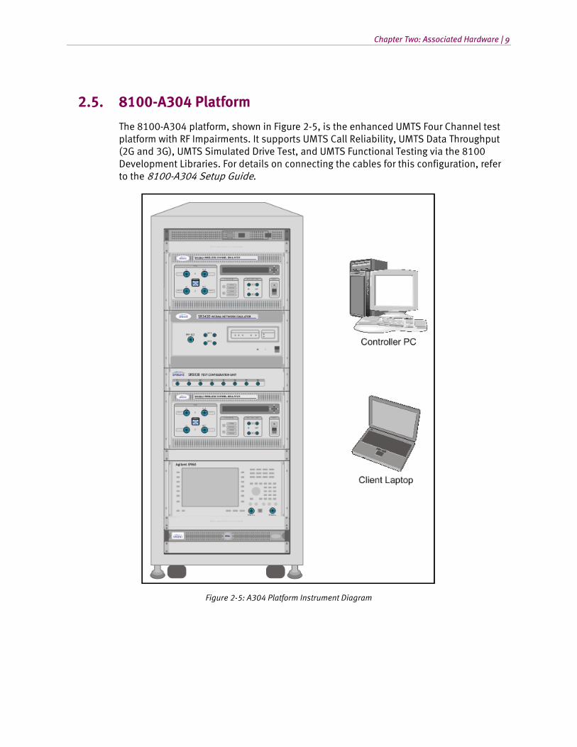
2.5. 8100-A304 Platform
The 8100-A304 platform, shown in Figure 2-5, is the enhanced UMTS Four Channel test platform with RF Impairments. It supports UMTS Call Reliability, UMTS Data Throughput (2G and 3G), UMTS Simulated Drive Test, and UMTS Functional Testing via the 8100 Development Libraries. For details on connecting the cables for this configuration, refer to the 8100-A304 Setup Guide.
Figure 2-5: A304 Platform Instrument Diagram

10 | 8100 Platform Manual
2.6. 8100-A400 Platform
The 8100-A400 platform, shown with the GSS6700 GNSS Simulator in Figure 2-6, is the ULTS ADS Test Platform. It supports the Spirent ULTS-ADS (A-GPS Development System) used to test A-GPS chipsets and modules before they are fully integrated into a wireless device. The 8100-A400 platform supports the GSS6560 (For existing customers only. this option is no longer for sale.), the GSS6700, or the GSS8000 GNSS Simulator.
Note that support for the STR4500 will be discontinued in the upcoming release. Existing STR4500 customers need to contact Spirent to replace their STR4500 unit with a GSS6700 unit.
The ADS Software Development Kit (ADS-SDK) is provided to develop the custom interface for the Device under Test. An external relay is used for time synchronization purposes. For details on connecting the cables for this configuration, refer to the 8100-A400 Setup Guides.
Figure 2-6: 8100-A400 Platform Configuration

Chapter Two: Associated Hardware | 11
2.7. 8100-A500 Platform
The 8100-A500 platform, shown with the GSS6700 GNSS Simulator in Figure 2-7, is the Validated ULTS RF Test Platform. It is Spirent’s flagship A-GPS test configuration used to test A-GPS enabled mobile devices. It supports RF Performance, Signaling Conformance (including SUPL), and Over-the-Air (OTA) Test Scenarios. This platform also supports GPS Service Interaction Functional Test Scenarios via the 8100 Development Libraries. The 8100-A500 supports the GSS6560 (For existing customers only. this option is no longer for sale.), the GSS6700, or the GSS8000 GNSS Simulator. For details on connecting the cables for this configuration, refer to the 8100-A500 Setup Guide.
Figure 2-7: 8100-A500 Platform Configuration
NOTE: A Client Laptop running the Spirent Data Client Software (not shown) is required to run GPS Service Interaction Tests on this platform. Contact your Regional Sales Manager to purchase the pre-configured Client Laptop.

12 | 8100 Platform Manual
2.8. 8100-A600 Platform
The 8100-A600 platform, shown with a GSS6700 in Figure 2-8, is the expanded ULTS test platform with RF Impairments with the Expansion Unit for multi-module support. It supports UMTS Location Test, UMTS Call Reliability, UMTS Data Throughput (2G & 3G), and UMTS Functional Testing via the 8100 Development Libraries. The 8100-A600 supports the GSS6560 (For existing customers only. this option is no longer for sale.) the GSS6700, and the GSS8000 GNSS Simulator. For details on connecting the cables for this configuration, refer to the 8100-A600 Setup Guide.
Figure 2-8: 8100-A600 Platform Configuration

Chapter Two: Associated Hardware | 13
2.9. 8100-A604 Platform
The 8100-A604 platform, shown with a GSS6560 in Figure 2-9, is the combined ULTS and UMTS Four Channel Platform with RF Impairments. It supports UMTS Location Test, UMTS Call Reliability, UMTS Data Throughput (2G & 3G), UMTS Simulated Drive Test, and UMTS Functional Testing via the 8100 Development Libraries. The 8100-A604 supports the GSS6560 (For existing customers only. this option is no longer for sale.) and the GSS6700 GNSS Simulator. For details on connecting the cables for this configuration, refer to the 8100-A604 Setup Guide.
Figure 2-9: 8100-A604 Platform Configuration

14 | 8100 Platform Manual
2.10. 8100-A750 Platform
The 8100-A750 platform shown a GSS6700 in Figure 2-10, is the entry level ULTS RF Test Platform. It supports RF Performance, Signaling Conformance (including SUPL), and Over-the-Air (OTA) Testing. This platform also supports GPS Service Interaction Functional Test Scenarios via the 8100 Development Libraries. The 8100-A750 platform supports the GSS6560 (For existing customers only. this option is no longer for sale.), the GSS6700, or the GSS8000 GNSS Simulator.
Note that support for the STR4500 will be discontinued in the upcoming release. Existing STR4500 customers need to contact Spirent to replace their STR4500 unit with a GSS6700 unit.
For details on connecting the cables for this configuration, refer to the 8100-A750 Setup Guide.
Figure 2-10: 8100-A750 Platform Configuration
NOTE: The step attenuator shown is used only in an OTA test configuration. In addition, the Client Laptop running the Spirent Data Client Software (not shown) is required to run GPS Service Interaction Tests on this platform. Contact your Regional Sales Manager to purchase the pre-configured Client Laptop.

Chapter Two: Associated Hardware | 15
2.11. 8100-B041 Platform
The 8100-B041 platform shown in Figure 2-11, is one of the Base LTE Test Platforms. It comes equipped with the S3110B Mobile Test Application used for comprehensive LTE Transmitter/Receiver testing. The 8100-B041 platform supports one LTE cell. Optional support for MIMO, Fading, and a second LTE cell are also available for this platform.
. Figure 2-11: 8100-B41 Platform Instrument Diagram

16 | 8100 Platform Manual
2.12. 8100-B051 Platform
The 8100-B051 platform shown in Figure 2-12 is one of the Base LTE Test Platforms. The 8100-B051 platform supports one LTE cell. Optional support for MIMO, Fading, and a second LTE cell are available for this platform.
For details on connecting the cables for these configurations, refer to the 8100-B051 Setup Guide.
. Figure 2-12: 8100-B51 Platform Instrument Diagram
Chapter Two: Associated Hardware | 17
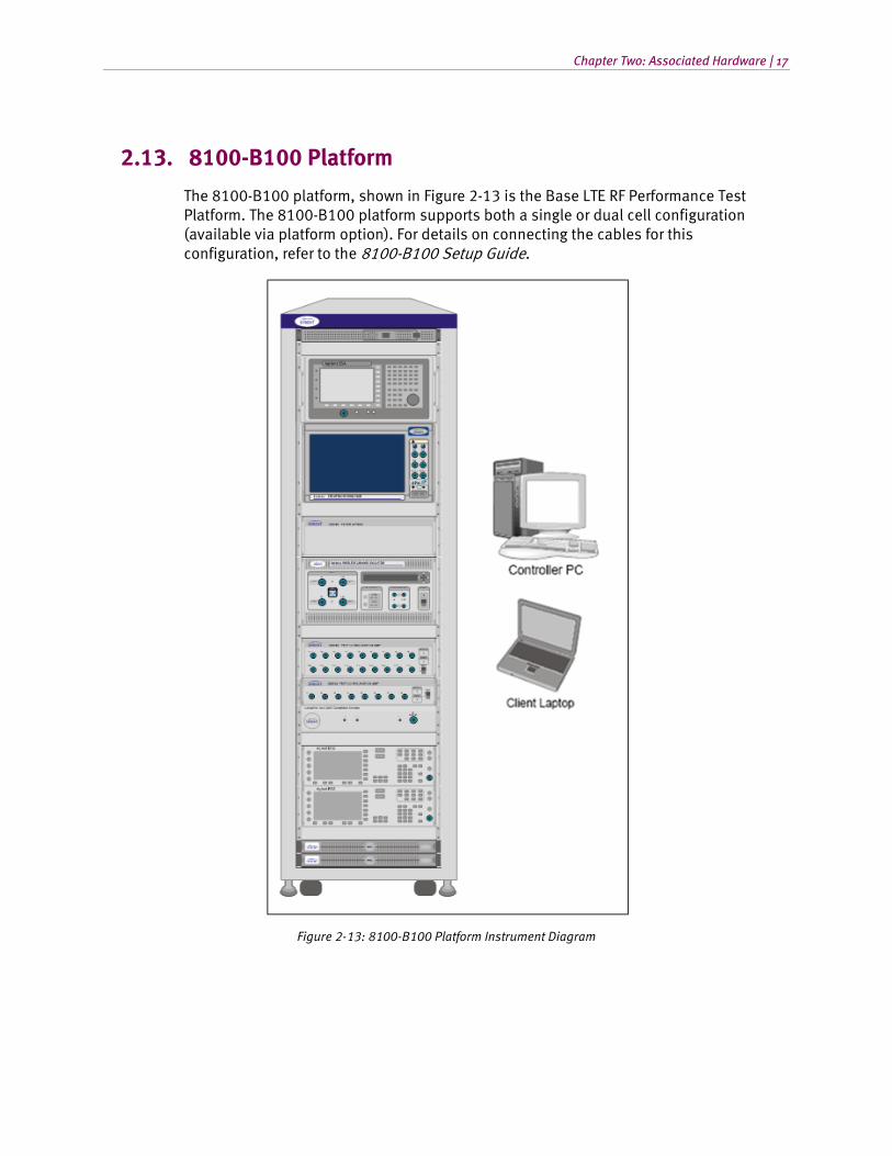
2.13. 8100-B100 Platform
The 8100-B100 platform, shown in Figure 2-13 is the Base LTE RF Performance Test Platform. The 8100-B100 platform supports both a single or dual cell configuration (available via platform option). For details on connecting the cables for this configuration, refer to the 8100-B100 Setup Guide.
Figure 2-13: 8100-B100 Platform Instrument Diagram

18 | 8100 Platform Manual
2.14. 8100-B200 Platform
The 8100-B200 platforms are shown in Figure 2-14. The 8100-B200 platform supports both LTE single and dual cell configurations. The 8100-B200 platform supports LTE Data Performance, LTE Data Retry, and LTE-InterRAT (CDMA and/or UMTS) modules.
For details on connecting the cables for these configurations, refer to the 8100-B200 Setup Guide.
Figure 2-14: 8100-B200 Platforms Instrument Diagram
Chapter Two: Associated Hardware | 19
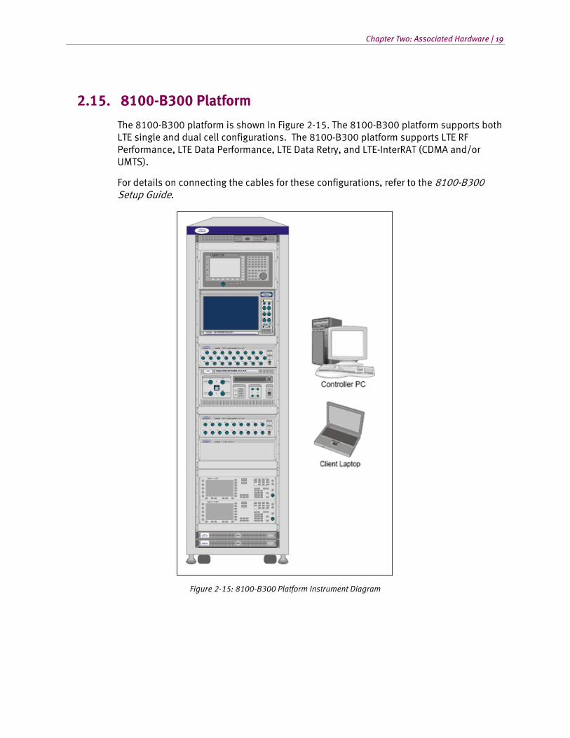
2.15. 8100-B300 Platform
The 8100-B300 platform is shown In Figure 2-15. The 8100-B300 platform supports both LTE single and dual cell configurations. The 8100-B300 platform supports LTE RF Performance, LTE Data Performance, LTE Data Retry, and LTE-InterRAT (CDMA and/or UMTS).
For details on connecting the cables for these configurations, refer to the 8100-B300 Setup Guide.
Figure 2-15: 8100-B300 Platform Instrument Diagram

20 | 8100 Platform Manual
2.16. 8100-B500 Platform
The 8100-B500 Series Platform is shown in Figure 2-16. This system supports LTE Location Testing Applications. The configuration shown in the diagram supports testing of LTE and CDMA capable devices. Other configurations that support UMTS are available.
For details on connecting the cables for these configurations, refer to the 8100-B500 Setup Guide.
Figure 2-16: 8100-B500 Platform Instrument Diagram

Chapter Two: Associated Hardware | 21
2.17. 8100-B502 Platform
The 8100-B502 Series Platform is shown in Figure 2-17. This system supports Multi-Cell LTE (up to 4 LTE Cells) Location Testing Applications. The configuration shown in the diagram below supports testing of LTE-only devices. Other configurations that support UMTS and CDMA are available.
For details on connecting the cables for these configurations, refer to the 8100-B502 Setup Guide.
Figure 2-17: 8100-B502 Platform Diagram

22 | 8100 Platform Manual
2.18. 8100-B600 Platform
The 8100-B600 Series Platform is shown in Figure 2-18.This platform supports LTE single and dual cell configurations, LTE RF Performance, and LTE Location Test Applications.
For details on connecting the cables for these configurations, refer to the 8100-B600 Setup Guide.
Figure 2-18: 8100-B600 Platform Diagram

Chapter Two: Associated Hardware | 23
2.19. 8100-B750 Platform
The 8100-B750 Series platform is shown in Figure 2-19. This system supports LTE Location Testing Applications. The configuration shown in the diagram supports testing of LTE and capable devices. Other configurations that support UMTS and CDMA are available.
For details on connecting the cables for these configurations, refer to the 8100-B750 Setup Guide.
Figure 2-19: 8100-B750 Platform Diagram

24 | 8100 Platform Manual
2.20. Instrument Descriptions
2.20.1. User Equipment (UE)
The term “UE” denotes the User Equipment under Test. For UMTS, the UE is usually a handset or Data Card connected to a PC or laptop.
2.20.2. SR5500 Wireless Channel Emulator
The SR5500 allows you to assess the capacity of a mobile device to mitigate multi-path effects by emulating the delay, fast and slow fading, and path-loss characteristics of RF mobile communication channels. The SR5500M TestKit software interface drives the emulator, which operates through the Test Manager Graphical User Interface.
Included in the following configurations: 8100-A100, A200, A300, A304, A600, and A604.
Optional in the following configurations: 8100-B100, B200, B300, and B500.
2.20.3. SR3420 WCDMA Network Emulator
The Spirent SR3420 is a scalable WCDMA Network Emulator. The SR3420 instrument coupled with the AirAccess WCDMA-HS control software provides emulation of all network components required to establish mobile data calls. It includes IP-connectivity through the Ethernet for optional connectivity to external data servers.
Included in the following configurations: 8100-A50, A100, A200, A300, A304, A500, A600, A604, and A750.
Optional in the following configurations: 8100-B200, B300, and B500.
2.20.4. E2010S LTE Network Emulator
The Spirent E2010S is a scalable LTE Network Emulator. The E2010S instrument coupled with the CS8 Interactive Tester control software provides emulation of all network components. These components are required to establish mobile data calls and include IP-connectivity through Ethernet for optional connectivity to external data servers.
The optional second cell hardware enables the E2010S to support Multi-Cell LTE test capabilities.
Included in the following configurations: 8100-B041, B051, B100, B200, B300, B500, B502, and B750.

Chapter Two: Associated Hardware | 25
2.20.5. SR3610 Core Network Emulator
The Core Network Emulator is a rack-mounted 1U PC that provides real-time Core Network emulation of the UMTS wireless system. The primary function of the emulator is to provide real-time user plane traffic (UDP/FTP/HTTP) routing to and from the UE and Application Server.
Now optional in the following configurations: 8100-A50, A100, A200, A300, A304, A600, and A604. Note that this HW option is only required to test PPP over PDCP for Data Throughput.
NOTE: As of April 2010, the SR3610 is no longer included in any of the 8100 UMTS Base Platforms.
2.20.6. SR3620 Enhanced Packet Core (EPC) Emulator
The Enhanced Packet Core (EPC) Emulator is a rack-mounted 1U PC that provides real-time Core Network emulation of 3G/4G wireless systems. The primary function of the emulator is to provide real-time user plane traffic (UDP/FTP/HTTP) routing to and from the UE and Application Server.
Included in the following configurations: 8100-B051, B100, B200, B300, B500, and B600.
2.20.7. Spirent STR4500 GPS Location Simulator
The STR4500 is a 12-channel L1 C/A code GPS Location Simulator used for Assisted GPS (A-GPS) testing. The STR4500 is capable of replaying pre-programmed test scenarios. TestDrive ULTS automatically configures the STR4500 through the SimPLEX/45 control software. This software provides complete, automated UE position-location testing.
The STR4500 is no longer available for sale and will not be supported following the next release. Existing 8100-A400 or A750 platforms customers must replace their units with GSS6700 units.
2.20.8. Spirent GSS6560 GPS Location Simulator
The GSS6560, a 12-channel L1 C/A code GPS Location Simulator used for Assisted GPS (A-GPS) testing. The GSS6560 features programmable parameters for customized test scenarios. TestDrive ULTS automatically configures the GSS6560 through the SimGEN control software. This software provides complete, automated UE position-location testing.
The GSS6560 is no longer available for sale, but can be used by existing customers on the 8100-A400, A500, A600, A604, and A750 platforms. Existing customers are encouraged to upgrade their systems to GSS6700 units.

26 | 8100 Platform Manual
2.20.9. Spirent GSS6700 GNSS Location Simulator
The GSS6700 is a single carrier (L1) with multi constellation (GPS, GLONASS, & GALILEO) and up to 48 Channel support GNSS simulator. GSS6700 simulator can be controlled by SimREPLAY or SimREPLAYplus or SimGEN software. ULTS supports SimREPLAYplus and SimGEN and may add SimREPLAY support in a future release.
Optional in the following configurations: 8100-A400, A500, A600, A604, A750 and B500..
2.20.10. Spirent GSS8000 GNSS Location Simulator
The GSS8000 is a three carrier (L1, L2, L5), multi constellation (GPS, GLONASS, GALILEO), and 48 Channel advanced GNSS simulator. GSS8000 is controlled by SimGEN software only.
For the 8100-A400, 8100-A750, or 8100-A500 systems we recommend at least twelve Channel L1 GPS and twelve Channel L1 GLONASS as a minimum requirement to support Assisted GLONASS (A-GLONASS) test cases.
Optional in the following configurations: 8100-A400, A500, A600, A750, and B500.
2.20.11. SR3920 Application Server PC
The Application Server uses the Windows Server 2003 Operating System. The SR3920 is a rack-mounted 1U PC that facilitates FTP/UDP/HTTP and alternating/bi-directional transfer capability to the Data Client PC. A Spirent Data Client Application runs on the server remotely managed by the Spirent Data Client application located on the Controller PC to provide this feature.
Included in the following configurations: 8100-B200 and B300.
Optional in the following configurations: 8100-A50, A100, A200, A300, A304, A600, A604, and B500.
It is required for UMTS Data Throughput, Data Call Reliability, and Data Mobility Test Themes. This is also optional on the 8100-A500 and A750 platforms for GPS Service Interaction Functional Testing (via 8100 Development Libraries).
2.20.12. SR3920 V2 Application Server PC
This Application Server is the replacement for the SR3920 and uses the Windows Server 2008 operating system. The SR3920 V2 is a rack-mounted 1U PC that facilitates FTP/UDP/HTTP and alternating/bi-directional transfer capability to the Data Client PC. To provide this feature, a Spirent Data Client Application runs on the server remotely managed by the Spirent Data Client application located on the Controller PC.
Included in the following configurations: 8100-B200 and B300.

Chapter Two: Associated Hardware | 27
Optional in the following configurations: 8100-A50, A100, A200, A300, A304, A600, A604, B500, and B600.
It is required for UMTS Data Throughput, Data Call Reliability, and Data Mobility Test Themes. This is also optional on the 8100-A500 and A750 platforms for GPS Service Interaction Functional Testing (via 8100 Development Libraries).
2.20.13. Client PC
The Client PC is a laptop that runs Microsoft Windows XP or Windows 7 32 bit OS. It facilitates FTP/UDP/HTTP and alternating/bi-directional transfer capability from the UE-side. A Spirent Data Client Application runs on the Data Client PC. It is remotely managed by the Data Client Controller located on the Controller PC. The Data Client PC also provides connectivity to support UE remote control for test automation.
Included in the following configurations: 8100-A100, A200, A300, A304, A600, A604, B100, B200, and B300 (optional on the 8100-A50 and B051 platforms).
This is also optional on the 8100-A500, A750, B500, and B600 platforms for GPS Service Interaction Functional Testing (via 8100 Development Libraries).
Note that Spirent Data Client software is required for GPS Service Interaction. You have the option of either buying a Data Client PC loaded with the software, or purchasing the software separately and installing it on your current PC.
2.20.14. Agilent 8960 Wireless Communications Test Set (Optional)
The Agilent 8960 is used to implement GPRS/EDGE air-interface specifications for base stations. This includes functions such as mobile registration, mobile and base station-initiated call connect and disconnect, call handoffs, and test modes.
Optional in the following configurations: 8100-A200, A300, A304, A600, and A604 (required for UMTS Data Throughput, if 2G testing is needed).
2.20.15. Agilent 3499A Switch/Control System
The Agilent 3499A Switch/Control System provides a high-speed, high-density electronic/optical switching solution for automatic test engineering applications. This module can accommodate up to five plug-in modules, routing up to 200 channels.
Included in the following configurations: 8100-A200, A300, A500, A600, and A604.
2.20.16. Agilent EPM-P Series Power Meter
The Agilent EPM-P series power meter is designed for peak, average, peak-to-average ratio, and time-gated measurements. The peak and average power sensor is provided to complete measurements.
Included in the following configurations: 8100-A200, A300, A500, A600, and A604.

28 | 8100 Platform Manual
Optional in the B500 configuration.
2.20.17. Agilent U2001A USB Power Sensor
The Agilent U2001A USB power sensor is used for calibration of the Spirent System. This power sensor is used in conjunction to with a signal source to determine downlink the insertion losses between network emulators, interference generators, and the device under test. It is also used to determine uplink insertion loss between the device under test and measurement devices such as a spectrum analyzer. The power sensor is not used for test case measurements.
Included in the following configurations: 8100-B100, B200, B300, and B600.
2.20.18. Ethernet Router
The Ethernet Router allows Ethernet communication with all instruments in the system. If connected to an existing network, it also provides a private network that isolates the instruments from external access. The router can operate with or without a connection to a corporate LAN or WAN.
Included in all configurations.
2.20.19. Ethernet Switch
The Ethernet Switch increases the numbers Ethernet connections in the system.
Included in the following configurations: 8100-A100, A200, A300, A600, and A604.
2.20.20. High-Speed Ethernet Switch
The High-Speed Ethernet Switch allows Ethernet communications with all instruments in systems that support 4G technologies. In such systems, the Router (refer to Section 2.20.18) is not used for Ethernet communications between the instruments in the system.
Included in the following configurations: 8100-B051, B100, B200, B300, B600, and B500.
2.20.21. SR5058 or SR5058L Test Configuration Unit
The SR5058 Test Configuration Unit automatically manages the switching of RF connections required for testing the UE. This allows the Mobile Device Test System to achieve the highest level of flexibility in test coverage.
Included in the following configurations: 8100-A200, A300, and A600.

Chapter Two: Associated Hardware | 29
2.20.22. SR5048 or SR5048L Test Configuration Unit
The SR5048 Test Configuration Unit automatically manages the switching of RF connections required for testing the UE. This allows the 8100 platforms to achieve the highest level of flexibility in test coverage.
Included in the following configurations: 8100-A500, A600, and A604.
2.20.23. SR5038 Test Configuration Unit
The SR5038 Test Configuration Unit automatically merges the output of the RF Downlink channels for the Enhanced UMTS Four Channel Test Platform. This allows the 8100 platform to support advanced network topologies test methodology.
Included in the following configurations: 8100-A304 and A604.
2.20.24. SR8078 Test Configuration Unit
The SR8078 Test Configuration Unit automatically merges the output of the RF Downlink channels for the LTE Test Platforms. This allows the 8100 platform to support advanced network topologies test methodology.
Included in the following configurations: 8100-B200 and B300.
2.20.25. SR8048 Test Configuration Unit
The SR8048 is used to switch various test equipment and impairment generation devices in and out of the signal paths as needed for a given test case. The SR4048 also includes the RF amplifiers and isolation circuits necessary to meet test conditions prescribed by wireless device testing standards.
An optional SR8048-Filter unit is required to provide optimal test conditions for the Receiver Blocking and Intermodulation tests.
Included in the following configurations: 8100-B100 and B300.
2.20.26. SR8068 Test Configuration Unit
The SR8068 Test Configuration Unit automatically manages the switching of RF connections required for testing LBS. This allows the 8100 platforms to achieve the highest level of flexible test coverage.
Included in the following configuration: 8100-B500.
Optional in the following configuration: 8100-A500.

30 | 8100 Platform Manual
2.20.27. Agilent E4438C ESG Vector Signal Generator
The Agilent ESG generator is used to provide CW tones and modulated interferers for LTE RF performance tests. At least one ESG is required for calibration of the LTE RF performance system.
At least one ESG is required in the following configurations: 8100-B100 and B300.
2.20.28. Agilent Spectrum/Signal Analyzer
The Agilent Spectrum/Signal Analyzer provides the measurement capability to make advanced mobile device transmitter measurements.
Optional in the following configurations: 8100-B100 and B300.
2.20.29. Controller PC
The Controller PC runs Microsoft Windows XP (Windows 7 OS coming soon) which hosts the Test Manager and TestDrive Software Executive. The Controller PC also hosts the AirAccess WCDMA-HS software, that configures and operates the SR3420 and the SR5500 TestKit software. The SR5500 software configures and operates the SR5500/SR5500M.
Included in all configurations.
Figure 2-20: Controller PC Software Components
Controller PC
AirAccess WCDMA-HS
Spirent ADS Router
Spirent OTA SDK Router
Spirent Data Client
Spirent SMLC
SimGEN
Test Manager
SR5500 TestKit
TestDrive ULTS
NI TestStand
SimPLEX/45
CS8 Interactive Tester
AirAccess C2K

Chapter Two: Associated Hardware | 31
2.21. Software Component Descriptions
The software components installed on the Controller PC are described in the following sections.
2.21.1. Test Manager
Test Manager is the Spirent Test Executive that serves as the front-end to Test Management and Control for all test themes except for ULTS (refer to Section 2.21.2 for details). This is the only interactive software component needed to accomplish most general testing. For more information on Test Manager, refer to the Test Manager User Manual.
Applicable on the following configurations: 8100-A50, A100, A200, A300, A304, A600, A604, B051, B100, B200, and B300.
Test Manager must also be activated on A500 and/or A750 platforms for GPS Service Interaction Functional Testing (via 8100 Development Libraries).
2.21.2. TestDrive ULTS
TestDrive ULTS is the Spirent Test Executive that serves as the front-end for the ULTS test theme. This is the only interactive software component needed to accomplish most general testing. For more information about TestDrive ULTS, refer to the ULTS User Manual.
Applicable on the following configurations: 8100-A400, A500, A600, A604, A750, and B500.
2.21.3. NI TestStand
Test Manager makes use of the National Instrument TestStand software as a back-end for managing tests. TestStand is an industry-standard test management environment that facilitates test automation and validation. Test Manager is designed to work seamlessly with TestStand. This increases the flexibility of interactive testing and gives an additional layer of test configurability.
Applicable on the following configurations: 8100-A50, A100, A200, A300, A304, A600, A604, B100, B200, and B300.
NI TestStand must also be activated on A500 and/or A750 platforms for GPS Service Interaction Functional Testing (via 8100 Development Libraries).

32 | 8100 Platform Manual
2.21.4. AirAccess WCDMA-HS
The AirAccess WCDMA-HS is a GSM/GPRS/R99/HSPA software interface layer that allows you to configure and control the SR3420 instrument. While essentially standalone software, the AirAccess WCDMA-HS application runs in the background while general testing requirements are met at the Test Manager front-end.
Applicable on the following configurations: 8100-A50, A100, A200, A300, A304, A500, A600, A604, A750, B051, B200, B300, and B500.
2.21.5. CS8 Interactive Tester
The CS8 Interactive Tester is an LTE software interface layer that allows you to configure and control the E2010S instrument. While essentially standalone software, the CS8 Interactive Tester application runs in the background while general testing requirements are met at the Test Manager front-end.
Applicable on the following configurations: 8100-B051, B200, B300, and B500.
2.21.6. AirAccess C2K
The AirAccess C2K is a CDMA/EV-DO software interface layer that allows you to configure and control the SR3452/SR3462 instruments. While essentially standalone software, the AirAccess C2K application runs in the background while general testing requirements are met at the Test Manager front-end.
Applicable on the following configurations: 8100-B051, B200, B300, and B500.
2.21.7. SimGEN GNSS Simulation Software
SimGEN is software application that allows you to customize GPS, GLONASS, and GALILEO (in the future) scenarios. It simulates pseudorange data for all visible satellites and communicates with the Spirent GNSS simulator to provide real-time RF emulation of a GPS network.
Applicable on the following configurations with GSS6560, GSS6700, or GSS8000: 8100-A400, A500, A600, A604, A750, and B500.

Chapter Two: Associated Hardware | 33
2.21.8. SimPLEX/45 GPS Simulation Software
SimPLEX/45 allows you to run test GPS scenarios on the STR4500. It simulates pseudorange data for all visible satellites and communicates with the Spirent GPS simulator. This communication allows for real-time RF emulation of a GPS network.
Applicable on the following configurations with STR4500: 8100-A400 and A750. The STR4500 is no longer available for sale and will not be supported following the next release. Existing 8100-A400 or A750 platforms customers must replace their units with GSS6700 units.
2.21.9. SR5500 TestKit
The SR5500 TestKit is a Spirent software application that manages the configuration and control of the SR5500M Wireless Channel Emulator. While essentially standalone software, the SR5500 Test Kit application runs in the background while general testing requirements are met at the Test Manager front-end.
Applicable on the following configurations: 8100-A100, A200, A300, A304, A600, A604, B100, B200, and B300.
Refer to the SR5500M User Manual for additional information on custom configurations for the SR5500M.
2.21.10. Spirent Data Client
The Spirent Data Client is a software application that manages FTP/UDP/HTTP data transfer between the Data Client PC and the Application Server PC. The Data Client Controller initiates all data throughput transfers, and relegates the transfer task to the Data Client and Application Server PC. The Test Manager manages the Data Client Controller application.
Applicable on the following configurations: 8100-A50, A100, A200, A300, A304, A600, A604, B200, B300, and B500.
Data Client software is also required on the A500 and/or A750 platforms for GPS Service Interaction Functional Testing (via 8100 Development Libraries).
2.21.11. Spirent SMLC Emulator
The Serving Mobile Location Centre (SMLC) is a network entity that manages the assistance data provided to the UE during an Assisted-GNSS (A-GPS or A-GLONASS) positioning session. The Spirent SMLC Emulator (SSE) presents a flexible solution to the testing challenges that result from the wide range of message content permitted by 3GPP standards. The SSE consists of a configurable state machine, providing full control of all assistance data provided to the UE during a test session. The user-friendly configuration interface provides a straightforward method for defining assistance data message content.

34 | 8100 Platform Manual
Applicable on the following configurations: 8100-A400, A500, A600, A604, A750, and B500.
2.21.12. Spirent ADS Router Software Development Kit
The Spirent ADS Router Software Development Kit (“ADS SDK”) is provided with the ULTS to facilitate development of a custom ADS Router. The ADS Router is a required software component in a ULTS-ADS system that routes messages between the TestDrive ULTS and the A-GPS development board. Refer to the ULTS-ADS Router SDK – Getting Started Guide for information on developing a custom ADS Router using the ADS SDK as a starting point.
The ADS SDK includes the following documents:
• Getting Started Guide.
• Message Specification for ULTS-ADS; describing the interface between TestDrive ULTS and ADS Router.
• ADS Router sample source code.
• Simulated GPS development board source code; including RRLP and RRC position response files.
Figure 2-21: Software Information and Settings Window

Chapter Two: Associated Hardware | 35
Figure 2-22: "About" Software Information
Applicable on the following configurations: 8100-A400, A500, A600, and A604.
2.21.13. Spirent OTA SDK Router Software Development Kit
8100-A500 or A750 with the CTIA OTA Testing option provides an interface module called the OTA Router. This router facilitates communication between Test Drive ULTS and various types of Positioners and Polarization Control units that are part of an Anechoic Chamber Control Hardware. The Spirent OTA SDK Router Software Development Kit (“OTA SDK”) is provided with the ULTS to facilitate customization of the OTA Router. Refer to the OTA SDK User Manual for information on how the OTA SDK helps you customize the interface to your Anechoic Chamber control hardware.
Applicable on the following configurations: 8100-A500, A600, A604, A750, and B500.
3. General Specifications
3.1. 8100-A50 General Specifications
Operating Temperature: 15 – 29 ‘C (Ambient Temperature)
Power Consumption (Typical): 300 to 350 Watts Continuous
3.2. 8100-A100 General Specifications
Operating Temperature: 15 – 29 ‘C (Ambient Temperature)
Dimensions (H x W x D): 57 x 23 x 37 inches (144.78 x 58.42 x 93.98 cm)
Power Consumption (Typical): 700 to 800 Watts Continuous
3.3. 8100-A200 General Specifications
Operating Temperature: 15 – 29 ‘C (Ambient Temperature)
Dimensions (H x W x D): 57 x 23 x 37 inches (144.78 x 58.42 x 93.98 cm)
Power Consumption (Typical): 1100 to 1200 Watts Continuous
3.4. 8100-A300 General Specifications
Operating Temperature: 15 – 29 ‘C (Ambient Temperature)
Dimensions (H x W x D): 57 x 23 x 37 inches (144.78 x 58.42 x 93.98 cm)
Power Consumption (Typical): 1100 to 1200 Watts Continuous

Chapter Three: General Specifications | 37
3.5. 8100-A304 General Specifications
Operating Temperature: 15 – 29 ‘C (Ambient Temperature)
Dimensions (H x W x D): 57 x 23 x 37 inches (144.78 x 58.42 x 93.98 cm)
Power Consumption (Typical): 1350 to 1450 Watts Continuous
3.6. 8100-A400 General Specifications
Operating Temperature: 15 – 29 ‘C (Ambient Temperature)
Power Consumption (Typical w/ GSS6560/6700): 150 to 200 Watts Continuous
Power Consumption (Typical w/ GSS8000): 450 to 500 Watts Continuous
3.7. 8100-A500 General Specifications
Operating Temperature: 15 – 29 ‘C (Ambient Temperature)
Dimensions (H x W x D): 57 x 23 x 37 inches (144.78 x 58.42 x 93.98 cm)
Power Consumption (Typical w/ GSS6560/6700): 550 to 600 Watts Continuous
Power Consumption (Typical w/ GSS8000): 850 to 900 Watts Continuous
3.8. 8100-A600 General Specifications
Operating Temperature: 15 – 29 ‘C (Ambient Temperature)
Dimensions (H x W x D): 77 x 23 x 37 inches (195.58 x 58.42 x 93.98 cm)
Power Consumption (Typical w/ GSS6560/6700): 1500 to 1550 Watts Continuous
Power Consumption (Typical w/ GSS8000): 1800 to 1850 Watts Continuous
38 | 8100 Platform Manual
3.9. 8100-A604 General Specifications
Operating Temperature: 15 – 29 ‘C (Ambient Temperature)
Dimensions (H x W x D): 77 x 23 x 37 inches (195.58 x 58.42 x 93.98 cm)
Power Consumption (Typical w/ GSS6560/6700 & Agilent 8960): 1400 to 1450 Watts Continuous
Power Consumption (Typical w/ GSS6560/6700 only): 1100 to 1150 Watts Continuous
3.10. 8100-A750 General Specifications
Operating Temperature: 15 – 29 ‘C (Ambient Temperature)
Dimensions (H x W x D): 57 x 23 x 37 inches (144.78 x 58.42 x 93.98 cm)
Power Consumption (Typical w/ GSS6560/6700): 425 to 475 Watts Continuous
Power Consumption (Typical w/ GSS8000): 725 to 775 Watts Continuous
3.11. 8100-B041 General Specifications
Operating Temperature: 15 – 29 ‘C (Ambient Temperature)
B041 (Single LTE Cell): Power Consumption (Typical): 450 to 550 Watts Continuous
B041 (Dual LTE Cell): Power Consumption (Typical): 600 to 700 Watts Continuous
3.12. 8100-B051 General Specifications
Operating Temperature: 15 – 29 ‘C (Ambient Temperature)
B051 (Single LTE Cell): Power Consumption (Typical): 800 to 900 Watts Continuous
B051 (Dual LTE Cell): Power Consumption (Typical): 950 to 1050 Watts Continuous
3.13. 8100-B100 General Specifications
Operating Temperature: 15 – 29 ‘C (Ambient Temperature)
Dimensions (H x W x D): 57 x 23 x 37 inches (144.78 x 58.42 x 93.98 cm)

Chapter Three: General Specifications | 39
Power Consumption (Typical w/ ESA, ESG, & GSS): 1700 to 1750 Watts Continuous
Power Consumption (Typical w/ no ESA, ESG, & GSS): 1100 to 1150 Watts Continuous
Power Consumption (Typical w/ GSS only): 1300 to 1350 Watts Continuous
3.14. 8100-B200 General Specifications
Operating Temperature: 15 – 29 ‘C (Ambient Temperature)
Dimensions (H x W x D): 77 x 23 x 37 inches (195.58 x 58.42 x 93.98 cm)
B200 Power Consumption – LTE Single Cell (Typical): 1150 to 1200 Watts Continuous
B200 Power Consumption – LTE Dual Cell (Typical): 1300 to 1350 Watts Continuous
3.15. 8100-B300 General Specifications
Operating Temperature: 15 – 29 ‘C (Ambient Temperature)
Dimensions (H x W x D): 77 x 23 x 37 inches (195.58 x 58.42 x 93.98 cm)
B300 Power Consumption – LTE Single Cell (Typical w/ ESA, ESG): 1550 to 1600 Watts Continuous
B300 Power Consumption – LTE Single Cell (Typical w/ no ESA, ESG): 1250 to 1300 Watts Continuous
B300 Power Consumption – LTE Dual Cell (Typical w/ ESA, ESG): 1700 to 1750 Watts Continuous
B300 Power Consumption – LTE Dual Cell (Typical w/ no ESA, ESG): 1400 to 1450 Watts Continuous
3.16. 8100-B500 General Specifications
Operating Temperature: 15 – 29 ‘C (Ambient Temperature)
Dimensions (H x W x D): 77 x 23 x 37 inches (195.58 x 58.42 x 93.98 cm)
B500 Power Consumption – LTE Single Cell (Typical with SR5500 and SR3452 units): Up to 1520-1600 Watts Continuous.
B500 Power Consumption – LTE Dual Cell (Typical w/ SR5500 and SR3452 units): Up to 1690-1770 Watts Continuous.

40 | 8100 Platform Manual
3.17. 8100-B600 General Specifications
Operating Temperature: 15 – 29 ‘C (Ambient Temperature)
Dimensions (H x W x D): 77 x 23 x 37 inches (195.58 x 58.42 x 93.98 cm)
B600 Power Consumption – LTE Single Cell (Typical w/ ESA, ESG): Up to 1400-1475 Watts Continuous.
B600 Power Consumption – LTE Dual Cell (Typical w/ ESA, ESG): Up to 1520 to 1600 Watts Continuous.
3.18. 8100-B750 General Specifications
Operating Temperature: 15 – 29 ‘C (Ambient Temperature)
3.18.1. B750
Dimensions (H x W x D): 77 x 23 x 37 inches (195.58 x 58.42 x 93.98 cm)
B750 Power Consumption – LTE Single Cell (Typical): 800 to 900 Watts Continuous
B750 Power Consumption – LTE Dual Cell (Typical): 950 to 1050 Watts Continuous
3.18.2. B750 plus CDMA
B750 Power Consumption – LTE Single Cell (Typical): 1000 to 1100 Watts Continuous
B750 Power Consumption – LTE Dual Cell (Typical): 1150 to 1300 Watts Continuous
3.18.3. B750 plus UMTS
B750 Power Consumption – LTE Single Cell (Typical): 1125 to 1225 Watts Continuous
B750 Power Consumption – LTE Dual Cell (Typical): 1300 to 1425 Watts Continuous

Chapter Three: General Specifications | 41
3.19. Supported Operating Bands
3.19.1. UMTS Operating Bands
The following UMTS operating bands are supported on the following platforms: 8100-A50, A100, A200, A300, A304, A500, A600, A604, and A750.
Operating Band
DL Frequencies (MHz) UL Frequencies (MHz)
I 2110 – 2170 1920 – 1980
II 1930 – 1990 1850 – 1910
III* 1805 – 1880 1710 – 1785
IV 2110 – 2155 1710 – 1755
V 869 – 894 824 – 849
VI 875 – 885 830 – 840
VIII 925 – 960 880 – 915
IX 1844.9 – 1879.9 1749.9 – 1784.9
XI* 1475.9 – 1500.9 1427.9 – 1452.9
* Frequency Bands only supported in the Data Throughput, Call Reliability, and Development Library Test Packs (including GPS Service Interaction).
3.19.2. GSM Operating Bands
The following GSM operating bands are supported on the following platforms: 8100-A50, A100, A200, A300, A304, A500, A600, A604, and A750.
Operating Band DL Frequencies (MHz) UL Frequencies (MHz)
GSM 850 869 - 894 824 - 849
P-GSM 900 935 - 960 890 - 915
DCS 1800 1805 - 1880 1710 - 1785
PCS 1900 1930 - 1990 1850 - 1910

42 | 8100 Platform Manual
3.19.3. LTE Operating Bands
The table below provides the Platform frequency information for LTE Operating Bands.
Operating Band DL Frequencies (MHz) UL Frequencies (MHz)
1 2110-2170 1920-1980
2 1930-1990 1850-1910
3 1805-1880 1710-1785
4 2110 - 2155 1710 - 1755
5 869-894 824-849
7 2620-2690 2500-2570
10 2110-2170 1710-1770
12 728-746 698-716
13 777 - 787 746 - 756
14 758-768 788-798
17 704 - 716 734 - 746
20 791-821 832-862
24 1525-1559 1626.5-1660.5
25 1930-1995 1850-1915
26 859-894 814-849
3.19.4. CDMA/EV-DO Operating Bands
The following CDMA/EV-DO operating bands are supported on the following platforms when upgraded from an existing CDMA system.
Operating Band DL Frequencies (MHz) UL Frequencies (MHz)
0 869-894 824 - 849
1 1930 - 1990 1850 - 1910
3 832 - 869 887 - 925
4 1840 - 1870 1750 - 1780
5 421 - 494 411 - 484
6 2110 - 2170 1920 - 1980
14 1930 - 1995 1850 - 1915
15 2110 - 2155 1710 - 1755
NOTE: For detailed information on specifications, refer to the appropriate User Manual for your test packs.

4. Frequently Asked Questions
4.1. How Do I Calibrate the Platform?
NOTE: Location-Based Test Packs (including GPS Service Interaction Functional Testing) require an independent calibration routine. Refer to Section 4.1.2 for Location Based Test Pack calibration (A500 and A600 platforms only)
4.1.1. Platform Calibration (for Test Manager Based Test Packs)
The calibration routine executes from the 8100-Axxx, 8100-B Series or the 8100-B100 Platform Files.
To initiate calibration for any Test Manager based test pack (including GPS Service Interaction Functional Testing on the A600 platform):
1. Open a platform file by selecting File>Platform File, as shown in Figure 4-1.
Figure 4-1: Opening the Platform File
2. Select the 8100-Axxx, 8100-B Series, or the 8100-B100 tab

44 | 8100 Platform Manual
Figure 4-2: The 8100-A300 Tab
3. From the 8100-Axxx tab, initiate the calibration routine using the Calibration Wizard platform file parameter. Click the Click here to execute button to initiate the calibration sequence.
4. From the 8100-B Series tab, ensure that the available instruments are set for the configuration you want to calibrate by selecting the True/False option in the file.
5. From the 8100-B Series tab, initiate the calibration routine using the Calibration Wizard platform parameter, as shown in Figure 4-3. Click the Click here to execute button to initiate the calibration sequence.
Figure 4-3: 8100-B Series Tab

Chapter Four: Frequently Asked Questions | 45
6. From the 8100-B100 tab, initiate the calibration routine using the Calibration Wizard platform parameter. Click the Click here to execute button to initiate the calibration sequence.
NOTE: For all platforms; use the N-Type and SMA-Type Torque Wrenches when removing and tightening cables.
Figure 4-4: 8100-B100Tab
7. When the Calibration Wizard is complete, save the Platform File before exiting, as shown in Figure 4-5.
Figure 4-5: Saving the Platform File

46 | 8100 Platform Manual
4.1.2. Location-based Test Pack Calibration (A500/A600/A604/B500/B502 Platforms)
Calibration for the 8100-B500 platform is not supported in this release. A default calibration file is used to compensate for the cellular path losses.
Calibration on the 8100-A500 platform is supported for both the SR8068 and SR5048.
For all platforms, the GPS calibration data is provided using the 8100-A500 procedure.
You must run the 8100-A500 calibration procedure prior to operating the 8100-B500 platform.
Refer to the Product Update for further information.
The calibration routine executes from the ULTS Test Executive.
To initiate calibration for any Location Based test pack (including GPS Service Interaction Functional Testing):
1. Select Execute>Calibration to launch the TestDrive ULTS Calibration Wizard, as shown in Figure 4-6.
Figure 4-6: Initiating the Location Based Calibration
2. The initial A500 Calibration Wizard window displays, as shown in Figure 4-7.

Chapter Four: Frequently Asked Questions | 47
Figure 4-7: Location Based Calibration Initialization (A500 Platform)
3. Click Next and follow the steps given in the Calibration Wizard.
NOTE: Use the N-Type and SMA-Type Torque Wrenches when removing and tightening cables.
4. When the Calibration Wizard is complete, follow the instructions listed to configure the ULTS system for testing.
5. The final Calibration Wizard window is shown in Figure 4-8.
Figure 4-8: Location Based Calibration - Confirmation/Reconfiguration Window

48 | 8100 Platform Manual
6. After the calibration is finished, the Calibration Data window displays data in tabular and graphical format, as shown in Figure 4-9.
Figure 4-9: Location Based Calibration - Calibration Data Window
The Calibration Data Window allows you to browse through the calibration data for various signal paths by selecting the Path number. A text description of the path is provided next to the path number. To track system drift over time, set TestDrive to record calibration data as a Reference Calibration by clicking the Store as Reference button, shown in Figure 4-9.
We recommend that you store the calibration data as a reference calibration the first time the system is assembled, and any time a major component in the system changes. Successive calibration runs are stored as the active calibration. Display Calibration Drift by changing the Data Set to Drift. You can view the complete calibration history in the Calibration History.mdb database.
4.2. Is there Anti-Virus Software Enabled for the System?
Yes.
Microsoft Security Essential (previously McAfee) is installed on the Controller PC with the Virus Scan option enabled. We recommend that you manually update the virus definition file with periodic full system scans. However, we cannot guarantee the fidelity of any session results while the system scan is active. We suggest you initiate these scans during off-peak execution of the system.