81 Security System Switcher
2
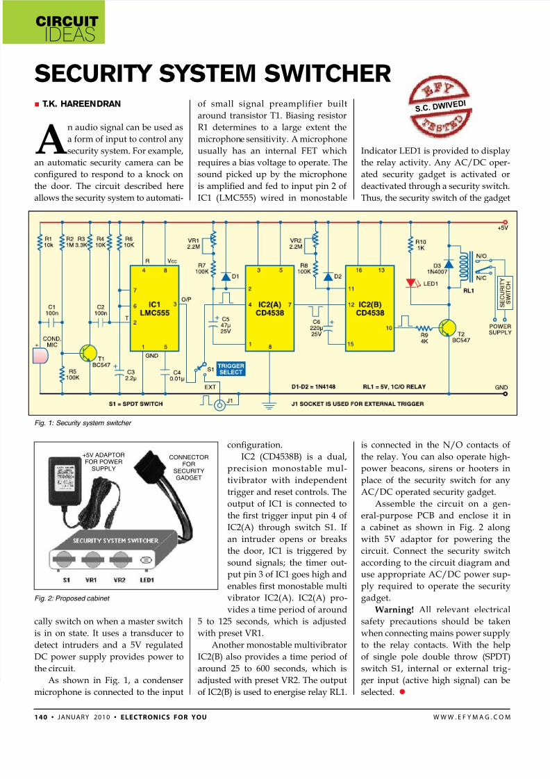
circuit ideas 140 • January 2010 • electronics for you www.efymag.com A audi sigal ca be used as a frm f iput t ctrl a securit sstem. Fr example, a autmatic securit camera ca be congured to respond to a knock on the dr. The circuit described here allws the securit sstem t autmati- call switch whe a master switch is i state. It uses a trasducer t detect itruders ad a 5V regulated DC pwer suppl prvides pwer t the circuit. As shw i Fig. 1, a cdeser micrphe is cected t the iput f small sigal preamplifier built arud trasistr T1. Biasig resistr R1 determies t a large extet the micrph e sesitivit. A micrphe usuall has a iteral FET which requires a bias vltage t perate. The sound picked up by the microphone is amplied and fed to input pin 2 of IC1 (LMC555) wired i mstable conguration. IC2 (CD4538B) is a dual, precisi mstable mul- tivibratr with idepedet trigger ad reset ctrls. The utput f IC1 is cected t the rst trigger input pin 4 of IC2(A) through switch S1. If an intruder opens or breaks the dr, IC1 is triggered b sud sigals; the timer ut- put pin 3 of IC1 goes high and enables rst monostable multi vibrator IC2(A). IC2(A) pro- vides a time perid f arud 5 to 125 seconds, which is adjusted with preset VR1. Ather mstable multivibratr IC2(B) also provides a time period of around 25 to 600 seconds, which is adjusted with preset VR2. The output of IC2(B) is used to energise relay RL1. T .K. Hareendran SecuriTy SySTem SwiTcHer s.c. d w i v e d i Fig. 1: Security system switcher Fig. 2: Proposed cabinet +5V ADAPTOR FOR POWER SUPPLY CONNECTOR FOR SECURITY GADGET Idicatr LED1 is prvided t displa the rela activit. A AC/DC per- ated securit gadget is activated r deactivated thrugh a securit switch. Thus, the securit switch f the gadget is cected i the n/o ctacts f the rela. yu ca als perate high- pwer beacs, sires r hters i place f the securit switch fr a AC/DC perated securit gadget. Assemble the circuit a ge- eral-purpse PCB ad eclse it i a cabinet as shown in Fig. 2 along with 5V adaptr fr pwerig the circuit. Cect the securit switch accrdig t the circuit diagram ad use apprpriate AC/DC pwer sup- pl required t perate the securit gadget. Warning! All relevat electrical safety precautions should be taken whe cectig mais pwer suppl t the rela ctacts. With the help of single pole double throw (SPDT) switch S1, internal or external trig - ger iput (active high sigal) ca be selected.
-
Upload
nagar-dinesh -
Category
Documents
-
view
223 -
download
0
Transcript of 81 Security System Switcher
8/6/2019 81 Security System Switcher
http://slidepdf.com/reader/full/81-security-system-switcher 1/1
circuit
ideas
140 • January 2010 • electronics for you w w w . e f y m a g . c o m
A audi sigal ca be used as
a frm f iput t ctrl asecurit sstem. Fr example,
a autmatic securit camera ca be
congured to respond to a knock on
the dr. The circuit described here
allws the securit sstem t autmati-
call switch whe a master switch
is i state. It uses a trasducer t
detect itruders ad a 5V regulated
DC pwer suppl prvides pwer t
the circuit.
As shw i Fig. 1, a cdesermicrphe is cected t the iput
f small sigal preamplifier built
arud trasistr T1. Biasig resistr
R1 determies t a large extet the
micrphe sesitivit. A micrpheusuall has a iteral FET which
requires a bias vltage t perate. The
sound picked up by the microphone
is amplied and fed to input pin 2 of
IC1 (LMC555) wired i mstable
conguration.
IC2 (CD4538B) is a dual,
precisi mstable mul-
tivibratr with idepedet
trigger ad reset ctrls. The
utput f IC1 is cected t
the rst trigger input pin 4 of
IC2(A) through switch S1. If
an intruder opens or breaks
the dr, IC1 is triggered b
sud sigals; the timer ut-
put pin 3 of IC1 goes high and
enables rst monostable multi
vibrator IC2(A). IC2(A) pro-
vides a time perid f arud
5 to 125 seconds, which is adjusted
with preset VR1.
Ather mstable multivibratr
IC2(B) also provides a time period of
around 25 to 600 seconds, which is
adjusted with preset VR2. The outputof IC2(B) is used to energise relay RL1.
T.K. Hareendran
SecuriTy SySTem SwiTcHer
s.c. d w i v e d i
Fig. 1: Security system switcher
Fig. 2: Proposed cabinet
+5V ADAPTOR
FOR POWER
SUPPLY
CONNECTOR
FOR
SECURITY
GADGET
Idicatr LED1 is prvided t displa
the rela activit. A AC/DC per-
ated securit gadget is activated r
deactivated thrugh a securit switch.
Thus, the securit switch f the gadget
is cected i the n/o ctacts f
the rela. yu ca als perate high-
pwer beacs, sires r hters i
place f the securit switch fr a
AC/DC perated securit gadget.
Assemble the circuit a ge-
eral-purpse PCB ad eclse it i
a cabinet as shown in Fig. 2 along
with 5V adaptr fr pwerig the
circuit. Cect the securit switch
accrdig t the circuit diagram ad
use apprpriate AC/DC pwer sup-
pl required t perate the securit
gadget.
Warning! All relevat electrical
safety precautions should be taken
whe cectig mais pwer suppl
t the rela ctacts. With the help
of single pole double throw (SPDT)
switch S1, internal or external trig-
ger iput (active high sigal) ca beselected.