8054/4451» - Google Compute Engine
36
4445446510 United States Patent [191 Sziklai [11] 4,454,610 i [451 Jun. 12, 1984 Buss et a1. ...................... .. 179/1 SA [54] METHODS AND APPARATUS FOR THE 4,076,960 2/ 1978 AUTOMATIC CLASSIFICATION 01? 4,126,373 11/1978 Moraw . . . . . . . . . , . . . . . . . .. 350/3.61 PATTERNS 4,150,781 4/ 1979 Silverman ..... .. 235/382 4,202,626 5/1980 Mayer et a1. . . . . . . . . . . . . .. 355/52 [75] Inventor: George C. Sziklai, Los Altos Hills, 4,213,036 7/1980 Kopp et al. . . . . . . . . . .. 382/43 Calif. 4,225,850 9/1980 Chang et al. . . . . . . . . . . . . .. 382/43 , . _ _ 4,310,721 1/l982 Manley et a1. ................. .. 119/1 SA [73] Ass1gnee: Transaction Sciences Corporation, - New Orleans, La. FOREIGN PATENT DOCUMENTS [211 App]_ NW 337,393 2653091 5/1978 Fed. Rep. of Germany . _ 1428469 3/ 1976 United Kingdom . [22] Flled: Jan. 6, 1982 OTHER PUBLICATIONS Related 115- Application Data Nemcek, et _al., “Experimental Investigation of Auto [63] continuatiomimpm of Sen No. 907,336, May 19, matic Signature Veri?cation”, Jan. 1974, 23% IEEE 1978, which is acontinuation of Ser. No. 118,453, Feb. Transactions on Systems and Cybernetics, vol- SMC, 4, 1980, abandoned. No. 1, pp. 121-126. [51] Int. Cl.3 . . . . . . . . . . . . . . . . . . . . .. G06K 9/00 Primary Examiner-Leo H. Boudreau [52] US. Cl. ...................................... .. 382/3; 235/380; Attorney, Agent, or Firm-Schapp and Hatch 235/494; 340/825.34; 382/31; 382/43 [58] Field of Search ............................. .. 382/3, 33-34, [57] . ABSTRACT 382/41-43; 179/1 SA; 235/457, 487, 489, 494, Methods and apparatus for the automatic classi?cation 470, 379-382; 340/ 825.3, 825.31, 825.34; of patterns are disclosed in which the intensity or gray 355/52 level values of selected pixels of digital images of func [56] References Cited tions of position-invariant transforms of patterns to be . classi?ed, displayed as intensity functions, are corre U'S' PATENT DOCUMENTS lated with one or more stored sets of values, each such 3,781,109 12/1973 Mayer, Jr. et a1. ................. .. 355/52 stored set of values corresponding to one of the classes 3,806,704 4/ 1974 Shinal ............... .. 235/61.7 B into which the unclassi?ed patterns are to be classi?ed. 3,346,752 11/ 1974 Nakalfo et 81 340/1463 Q Methods of determining the coordinates of the selected gadchffe, ' ' ' ' ' ' ' ' ' ' ' ' ' ‘ ‘ " pixels for use in automatic signature ver?cation and 3’894’756 7/1975 wtryd 283/7 automatic handwritten numeral recognition are dis 4,014,602 3/1977 Ruell . . . . . . . . . . . . . .. 350/35 9108“ 4,034,2l1 7/1977 Horst et al. 235/61.l2 N 4,073,010 2/ 1978 Casasent et al .................... .. 382/43 13 Claims, 24 Drawing Figures [ Z 52 IUHIBI PEERLESS PRINTING CO.. INC. NE“ ORLEANS. LOUISIANA 70130 ‘ 1111 DATE |9 _ 650 P832158? 8 DOLLARS WHITNEY NATIONAL BANK OF NEW ORLEANS :‘H P': mesa-"001.11: 1.2-»31. 50-2, '18“ 8054/4451» 250/ K25.
Transcript of 8054/4451» - Google Compute Engine

4445446510
United States Patent [191 Sziklai
[11] 4,454,610 i [451 Jun. 12, 1984
Buss et a1. ...................... .. 179/1 SA [54] METHODS AND APPARATUS FOR THE 4,076,960 2/ 1978 AUTOMATIC CLASSIFICATION 01? 4,126,373 11/1978 Moraw . . . . . . . . . , . . . . . . . .. 350/3.61
PATTERNS 4,150,781 4/ 1979 Silverman ..... .. 235/382 4,202,626 5/1980 Mayer et a1. . . . . . . . . . . . . .. 355/52
[75] Inventor: George C. Sziklai, Los Altos Hills, 4,213,036 7/1980 Kopp et al. . . . . . . . . . .. 382/43 Calif. 4,225,850 9/1980 Chang et al. . . . . . . . . . . . . .. 382/43
, . _ _ 4,310,721 1/l982 Manley et a1. ................. .. 119/1 SA [73] Ass1gnee: Transaction Sciences Corporation, -
New Orleans, La. FOREIGN PATENT DOCUMENTS
[211 App]_ NW 337,393 2653091 5/1978 Fed. Rep. of Germany . _ 1428469 3/ 1976 United Kingdom .
[22] Flled: Jan. 6, 1982 OTHER PUBLICATIONS
Related 115- Application Data Nemcek, et _al., “Experimental Investigation of Auto [63] continuatiomimpm of Sen No. 907,336, May 19, matic Signature Veri?cation”, Jan. 1974, 23% IEEE
1978, which is acontinuation of Ser. No. 118,453, Feb. Transactions on Systems and Cybernetics, vol- SMC, 4, 1980, abandoned. No. 1, pp. 121-126.
[51] Int. Cl.3 . . . . . . . . . . . . . . . . . . . . .. G06K 9/00 Primary Examiner-Leo H. Boudreau
[52] US. Cl. ...................................... .. 382/3; 235/380; Attorney, Agent, or Firm-Schapp and Hatch 235/494; 340/825.34; 382/31; 382/43
[58] Field of Search ............................. .. 382/3, 33-34, [57] . ABSTRACT 382/41-43; 179/1 SA; 235/457, 487, 489, 494, Methods and apparatus for the automatic classi?cation
470, 379-382; 340/ 825.3, 825.31, 825.34; of patterns are disclosed in which the intensity or gray 355/52 level values of selected pixels of digital images of func
[56] References Cited tions of position-invariant transforms of patterns to be . classi?ed, displayed as intensity functions, are corre
U'S' PATENT DOCUMENTS lated with one or more stored sets of values, each such 3,781,109 12/1973 Mayer, Jr. et a1. ................. .. 355/52 stored set of values corresponding to one of the classes 3,806,704 4/ 1974 Shinal ............... .. 235/61.7 B into which the unclassi?ed patterns are to be classi?ed. 3,346,752 11/ 1974 Nakalfo et 81 340/1463 Q Methods of determining the coordinates of the selected
gadchffe, ' ' ' ' ' ' ' ' ' ' ' ' ' ‘ ‘ " pixels for use in automatic signature ver?cation and
3’894’756 7/1975 wtryd 283/7 automatic handwritten numeral recognition are dis 4,014,602 3/1977 Ruell . . . . . . . . . . . . . .. 350/35 9108“
4,034,2l1 7/1977 Horst et al. 235/61.l2 N 4,073,010 2/ 1978 Casasent et al .................... .. 382/43 13 Claims, 24 Drawing Figures
[ Z 52 IUHIBI
PEERLESS PRINTING CO.. INC. NE“ ORLEANS. LOUISIANA 70130
‘ 1111
DATE |9 _ 650
P832158? 8
DOLLARS
WHITNEY NATIONAL BANK OF NEW ORLEANS
:‘H P': mesa-"001.11: 1.2-»31. 50-2, '18“ 8054/4451» 250/ K25.

US. Patent Jun. 12, 1984 Sheet 1 of 13 4,454,610
PIE- -1

US. Patent Jun. 12, 1984 Sheet 2 of 13 4,454,610


U.S. Patent Jun. 12, 1984
ORIGINATION A B C D E F G H 1 1A 1B 1C 1D
2 2A 2B
IJKL
Sheet 5 of 13
>42 02 o2
>LO 02
4,454,610
m2 §> 1K 1L m 8K 8L ,ag 101 IOJ 10K 10L “91%) “03
10 10A 108
_____.___.>
PIE- -ZEZ
U.S. Patent Jun. 12, 1984 Sheet 6 of 13 4,454,610

U.S. Patent‘ Jun. 12, 1984 Sheet 7 of 13 4,454,610


US. Patent Jun. 12, 1984 Sheet 9 of 13 4,454,610
-N-- LN-HWH
To? 7N2 .\ .x 5538 55528 255
is 252558 3 292.558 @333
I2 1
N:\\
_-Q_\
Qt

U.S. Pat?nt Jun. 12, 1984 Sheet 10 of 13 4,454,610
- m. - LN. Hmn 43/.
‘:5 953.35 E
n: w
A ouw\_>5z 5% A ouw\ 2:2
3% {3
EN
E: . mm 295 NTIIF “ KEEZES. 1i
EMEQE \ISMI \. _ Ga
mokumqmm 0Q hm?kmxo 000 0 NW 30 moo UH ~00 Moo

U.S. Patent Jun. 12, 1984 Sheet 11 of 13 4,454,610
wmNJ mix-.25
gm. .UZH =00 UZHHZHMTH wwmnwhmmmmmm

» U.S.> Patent Jun. 12,1984 Sheet 12 of 13 I 4,454,610
1 ‘Lu-5i FIE-.lEIA. CC: 2 2%
(mist) 1. FIE--11
:EIEr-JJJB_
1 FIE--IDEI
FIE--IDD
.7 PIE--1DE-'
7 FIE--IDF.
/ 2 3 4 5 6 7 5 q 0 7‘ FIE-.IDE
PIE--lDH


4,454,610 1
METHODS AND APPARATUS FOR THE AUTOMATIC CLASSIFICATION OF PA'ITERNS
This is a continuation-in-part of US. patent applica tion Ser. No. 907,836, ?led May 19, 1978 and a continu- ‘ ation of US. patent application Ser. No. 118,453, ?led Feb. 4, 1980, now abandoned
BACKGROUND OF THE INVENTION
1. Field of the Invention My invention relates to methods and apparatus for
the automatic classi?cation of patterns, and more partic ularly to methods and apparatus of the class including those disclosed in my co-pending US. patent applica tion, Ser. No. 907,836, ?led May 19, 1978, the teachings of which are incorporated herein by reference. It will be understood by those having ordinary skill in the art, informed by the teachings of these two patent applica tions, thatlcertain ones of the cryptographic teachings of my said co-pending application may be incorporated into systems embodying my present invention by those having ordinary skill in the art without the exercise of invention. The expression “automatic classi?cation of indicia”
as used herein denotes but is not limited to optical char acter recognition (OCR) and automatic signature veri? cation.
2. Description of the Prior Art Many methods and apparatus for the automatic classi
?cation of patterns are found in the prior art. Holographic methods and apparatus for the classi?
cation of patterns are shown and described in US. Pat. Nos. 3,620,590; 3,643,216; and 4,053,228. See also, “Ho lographic Filing: An Industry on the Verge of Birt ”, by Thomas H. Maugh II, Science, Vol. 201, Aug. 4, 1978, pages 431 and 432.
It is suggested at pages 177 through 184 of Introcu duction to Fourier Optics, by Joseph W. Goodman, McGraw-Hill, 1968, that optical data processing meth ods and apparatus may be applied to character recogni tion. Most of these prior art methods and apparatus have,
however, been characterized by complexity and high cost, and have involved many steps of human judge ment and selection in their design.
SUMMARY OF THE INVENTION
Accordingly, it is an object of my invention to pro
25
30
35
45
50 vide methods and apparatus for the automatic classi?ca- _ tion of patterns which are simpler, less complex, less costly, and more reliable than the prior art methods and apparatus.
It is a further object of my invention to provide meth ods and apparatus for the automatic determination of certain parameters of particular automatic pattern clas si?cation devices embodying my invention. Other objects and aspects of my invention will in part
be obvious and will in part appear hereinafter. My invention, accordingly, comprises the several
steps, and the relation of one or more such steps with respect to each of the others, and the apparatus em bodying features of construction, combinations of ele ments, and arrengements of parts which are adapted to effect such steps, all as exempli?ed in the following disclosure, and the scope of my invention will be indi cated in the appended claims.
55
65
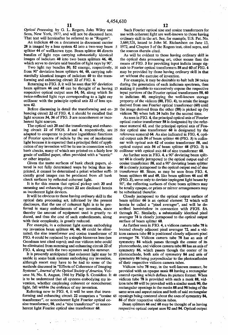
2 In accordance with one aspect of my invention, an
automatic pattern classi?cation device comprises a pat tern spectrum generator, which generates partial repre sentations of functions of pattern spectra from patterns which are successively presented to it, and further com prises a small plurality, e.g., 30, of gray level or intensity value detectors (sometimes hereinfter called “pixel value detectors” or “pixel detectors”) each of which is operatively related in gray level or intensity value de tecting relation to a corresponding pixel or element of each successive one of said partial representations of functions of pattern spectra. The plurality of pixels juxtaposed to said detectors when a particular pattern is presented to said pattern spectrum generator will here inafter be called an “unclassi?ed pixel constellation”. The corresponding plurality of gray level or intensity values sensed by said detectors will hereinafter be called the corresponding “unclassi?ed pixel value set”.
In accordance with another aspect of my invention, methods are provided for determining the unclassi?ed pixel constellations for particular pattern classi?cation devices embodying my invention, which methods may be carried out by image processing systems of well known type.
In accordance with another aspect of my invention, some of said pattern classi?cation devices comprise a plurality of memory devices or locations each contain ing a set of gray level or intensity value representations corresponding to a particular one of the set of classes into which the unclassi?ed patterns, i'.e., the patterns presented to the pattern spectrum generator, are to be classi?ed. Such a set of values may hereinafter be called a “class value set” or “classi?cation value set”.
In accordance with another aspect of my invention, some indicium or pattern classi?cation devices thereof comprise a single memory containing a single set of gray level or intensity value representations, and the indicia presented to the associated indicium spectrum generator are classi?ed as having or not having the same signi?cation and/or origination as the indicium from which said representations were derived.
In accordance with another aspect of my invention, indicia may be classi?ed in accordance with two prop erties, viz., origination and signi?cation, “origination” meaning generally the generating source of a particular indicium, and “signi?cation” meaning generally the immediate, primary, or apparent meaning of a particular indicium. When a class value set as de?ned above is adapted to
be used in classifying indicia according to their signi? cation only it may be called a “signi?cation value se ”. When a class value set as de?ned above is adapted to be used in classifying indicia according to their origination only, it may be called an “origination value set”. The corresponding set of gray level or intensity values de rived friom an unclassi?ed indicium by the indicium spectrum generator may be called an “unclassi?ed indi cium value set” or “unclassi?ed value set”.
In accordance with another aspect of my invention, methods and apparatus are provided for determining the class value sets to be employed in particular pattern classi?cation devices embodying my invention, and more particularly methods and apparatus are provided for determining the signi?cation value sets, the origina tion value sets, or both to be used in particular indicium classi?cation devices embodying my invention. It is to be noted that my invention contemplates certain em bodiments in which theretofore unclassi?ed indicia are

4,454,610 3
to be classi?ed in accordance with both their signi?ca tion and their origination.
In accordance with another aspect of my invention, each unclassi?ed value set produced by a pattern spec trum generator of a particular pattern classi?cation device of my invention is to be correlated with each of the one or more classi?cation value sets stored in the memory of that device, or on the document bearing the corresponding unclassi?ed pattern in printed or other convenient form, in accordance with the one dimensional correlation formula of FIG. 11, and the most probable classi?cation of the unclassi?ed pattern is to be indicated by suitable indicating means or the docu ment rejected by suitable rejecting means if the correla tion coef?cient value corresponding to the unclassi?ed value set is less than a predetermined threshold value.
In accordance with another aspect of my invention, a pattern classi?cation device embodying my invention may be provided with indicating means to indicate that an unclassi?ed pattern presented for classi?cation is not a member of any of the classes to which the class value sets stored in its memory devices or locations corre spond. 4
In accordance with another aspect of my invention, each unclassi?ed value set produced by an indicium spectrum generator of a particular type of indicium classi?cation device of my invention is to be correlated with a single class value set which is derived from the document bearing the corresponding unclassi?ed indi cium, and suitable indicating means is provided to indi cate whether the unclassi?ed indicium presented falls within the class of indicia corresponding to said single class value set or does not. For a fuller understanding of the nature and objects
of my invention reference should be had to the follow ing detailed description, taken in connection with the accompanying drawings. BRIEF DESCRIPTION OF THE DRAWINGS
FIG. 1 illustrates a partial digital image of a logarith mic function of the Fourier spectrum of a handwritten signature, displayed as an intensity function; FIG. 2 illustrates a small portion of an “insular pixel”
digital log Fourier signature spectrum as displayed on the display tube of an indicium spectrum generator of my invention; FIG. 2A is an indicium chart of a kind which might
be used in constructing an embodiment of my invention; FIG. 2B illustrates an indicium spectrum matrix of a
kind which might be used in constructing an embodi ment of my invention; ‘ FIG. 20 illustrates the methods of my invention for
determining the unclassi?ed pixel constellations of in dicum classi?cation devices embodying my invention; FIGS. 3, 4, 5A, 5B, and 5C schematically represent a
pattern spectrum generator which may be used in an indicium classi?cation device embodying my invention; FIGS. 6 through 8 together constitute a schematic
diagram of a handwritten numeral reader embodying my invention; FIG. 9 shows a bank check of a kind adapted for use
in connection with an embodiment of my invention; FIGS. 10A through 10D illustrate handwritten arabic
numerals of the same signi?cation but different origina tion; '
FIGS. 10E through 10G illustrate handwritten arabic numerals of the same signi?cation but different origina tion;
20
25
35
40
50
55
65
4 FIG. 10H illustrates a set of handwritten arabic nu
merals of the same origination or “style”; FIG. 11 represents as a mathematical formula the
one-dimensional correlation coef?cient determining algorithm employed in indicium classi?cation devices embodying my invention; and FIG. 12 is a schematic diagram of a handwritten
signature veri?er embodying my invention.
DESCRIPTION OF PREFERRED EMBODIMENTS ’
Before describing particular embodiments of my in vention, the general principles and technological con text thereof will be described in detail.
Referring now to FIG. 1, there is represented a par tial digital image of the (absolute) magnitude of the two-dimensional Fourier spectrum of a handwritten ‘ signature, logarithmically enhanced and displayed as an intensity function.
In describing digital images of patterns or their spec tra hereinafter, the terminology and conventions em ployed in Digital Image Processing. by Rafael C. Gonza lez and Paul Wintz, published by Addison-Wesley Pub lishing Company, Inc., 1977, (hereinafter “Gonzalez Wintz”) will generally be observed unless the context indicates otherwise.
Particular reference is had to pages 5, 6, and 21 through 31 of Gonzalez-Wintz at which terminology and conventions for describing digital images are dis cussed; and pages 38 through 51 of Gonzalez-Wintz at which the two-dimensional Fourier transform, both continuous and discrete, and the logarithmic enhance ment of intensity function displays of Fourier spectra are discussed. In this connection, it is to be noted that the expression “digital image” may sometimes be used herein to denote not only a particular light intensity function (cf., Gonzalez-Wintz, page 5) but also the cor responding digital image representation (cf., Gonzalez Wintz, page 6, FIG. 1.5). The term “representation” as used herein is not lim
ited to human-viewable displays, but rather also em braces corresponding data stored in computer memories and the like. The partial digital image representation of FIG. 1 is
of the continuous or “no-background” type which may be used in some embodiments of my invention. It is to be understood, however, that other types of digital image representations of functions of spectra of handwritten signatures, displayed as intensity functions, (e.g., wherein the elements or “pixels” are set in a substan tially uniform background) may also be used in practic ing my invention.
It is also to be understood that representations of partial digital images of logarithmic functions of the Fourier spectra of handwritten signatures, displayed as intensity functions, will sometimes be called “digital log Fourier signature spectra” herein, whether they are of the “no-background” type or of the “background” or “isolated pixel” type.
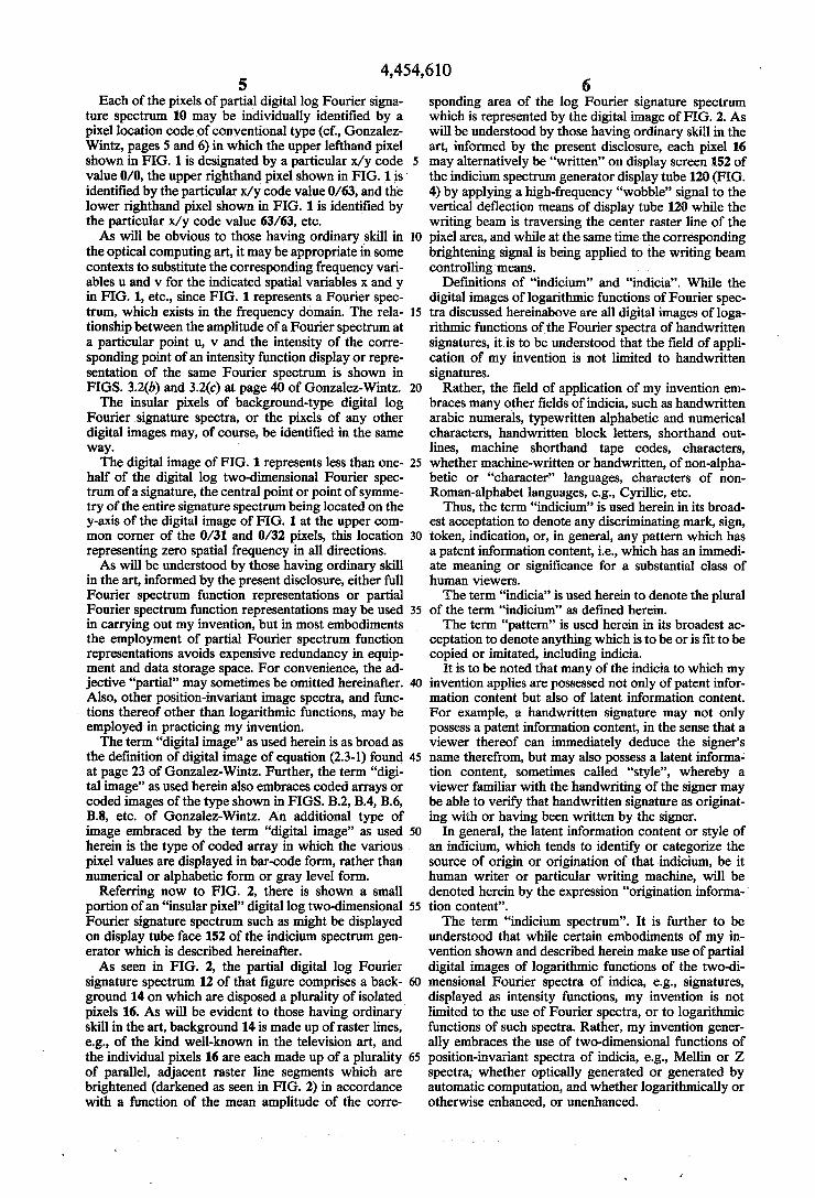
Referring again to FIG. 1, it can be seen that the partial digital log Fourier signature spectrum 10 of FIG. 1 is a 64x64 array of halftone pixels, each pixel im printed at one of sixteen gray level values or intensity values. It is to be understood that the term “intensity” as used herein is to be taken as synonymous with the ex pressions “gray level value” and “intensity value” un less the context indicates otherwise.
4,454,610 5
Each of the pixels of partial digital log Fourier signa ture spectrum 10 may be individually identi?ed by a pixel location code of conventional type (cf., Gonzalez Wintz, pages 5 and 6) in which the upper lefthand pixel shown in FIG. 1 is designated by a particular x/ y code value 0/0, the upper righthand pixel shown in FIG. 1 is ' identi?ed by the particular x/ y code value 0/63, and the lower righthand pixel shown in FIG. 1 is identi?ed by the particular x/y code value 63/63, etc. As will be obvious to those having ordinary skill in
the optical computing art, it may be appropriate in some contexts to substitute the corresponding frequency vari ables u and v for the indicated spatial variables x and y in FIG. 1, etc., since FIG. 1 represents a Fourier spec trum, which exists in the frequency domain. The rela tionship between the amplitude of a Fourier spectrum at a particular point u, v and the intensity of the corre sponding point of an intensity function display or repre sentation of the same Fourier spectrum is shown in FIGS. 3.2(b) and 3.2(c) at page 40 of Gonzalez-Wintz. The insular pixels of background-type digital log
Fourier signature spectra, or the pixels of any other digital images may, of course, be identi?ed in the same way. The digital image of FIG. 1 represents less than one
half of the digital log two-dimensional Fourier spec trum of a signature, the central point or point of symme try of the entire signature spectrum being located on the y-axis of the digital image of FIG. 1 at the upper com mon comer of the 0/31 and 0/32 pixels, this location representing zero spatial frequency in all directions. As will be understood by those having ordinary skill
in the art, informed by the present disclosure, either full Fourier spectrum function representations or partial Fourier spectrum function representations may be used in carrying out my invention, but in most embodiments the employment of partial Fourier spectrum function representations avoids expensive redundancy in equip ment and data storage space. For convenience, the ad jective “partial” may sometimes be omitted hereinafter. Also, other position-invariant image spectra, and func tions thereof other than logarithmic functions, may be employed in practicing my invention. The term “digital image” as used herein is as broad as
the de?nition of digital image of equation (2.3-1) found at page 23 of Gonzalez-Wintz. Further, the term “digi tal image” as used herein also embraces coded arrays or coded images of the type shown in FIGS. B.2, B.4, B6, B8, etc. of Gonzalez-Wintz. An additional type of image embraced by the term “digital image” as used
20
25
30
35
40
45
herein is the type of coded array in which the various . pixel values are displayed in bar-code form, rather than numerical or alphabetic form or gray level form.
Referring now to FIG. 2, there is shown a small portion of an “insular pixel” digital log two-dimensional Fourier signature spectrum such as might be displayed on display tube face 152 of the indicium spectrum gen erator which is described hereinafter. As seen in FIG. 2, the partial digital log Fourier
signature spectrum 12 of that ?gure comprises a back ground 14 on which are disposed a plurality of isolated pixels 16. As will be evident to those having ordinary ' skill in the art, background 14 is made up of raster lines, e.g., of the kind well-known in the television art, and the individual pixels 16 are each made up of a plurality of parallel, adjacent raster line segments which are brightened (darkened as seen in FIG. 2) in accordance with a function of the mean amplitude of the corre
60
65
6 sponding area of the log Fourier signature spectrum which is represented by the digital image of FIG. 2. As will be understood by those having ordinary skill in the art, informed by the present disclosure, each pixel 16 may alternatively be “written” on display screen 152 of the indicium spectrum generator display tube 120 (FIG. 4) by applying a high-frequency “wobble” signal to the vertical de?ection means of display tube 120 while the writing beam is traversing the center raster line of the pixel area, and while at the same time the corresponding brightening signal is being applied to the writing beam controlling means.
De?nitions of “indicium” and “indicia”. While the digital images of logarithmic functions of Fourier spec tra discussed hereinabove are all digital images of loga rithmic functions of the Fourier spectra of handwritten signatures, it is to be understood that the ?eld of appli cation of my invention is not limited to handwritten signatures.
Rather, the field of application of my invention em braces many other ?elds of indicia, such as handwritten arabic numerals, typewritten alphabetic and numerical characters, handwritten block letters, shorthand out lines, machine shorthand tape codes, characters, whether machine-written or handwritten, of non-alpha betic or “character” languages, characters of non Roman-alphabet languages, e.g., Cyrillic, etc.
Thus, the term “indicium” is used herein in its broad est acceptation to denote any discriminating mark, sign, token, indication, or, in general, any pattern which has a patent information content, i.e., which has an immedi ate meaning or signi?cance for a substantial class of human viewers. The term “indicia” is used herein to denote the plural
of the term “indicium” as de?ned herein. The term “pattern” is used herein in its broadest ac
ceptation to denote anything which is to be or is ?t to be copied or imitated, including indicia.
It is to be noted that many of the indicia to which my invention applies are possessed not only of patent infor mation content but also of latent information content. For example, a handwritten signature may not only possess a patent information content, in the sense that a viewer thereof can immediately deduce the signer’s name therefrom, but may also possess a latent informa4 tion content, sometimes called “style”, whereby a viewer familiar with the handwriting of the signer may be able to verify that handwritten signature as originat ing with or having been written by the signer.
In general, the latent information content or style of an indicium, which tends to identify or categorize the source of origin or origination of that indicium, be it human writer or particular writing machine, will be denoted herein by the expression “origination informa tion conten ”. The term “indicium spectrum”. It is further to be
understood that while certain embodiments of my in vention shown and described herein make use of partial digital images of logarithmic functions of the two-di mensional Fourier spectra of indica, e. g., signatures, displayed as intensity functions, my invention is not limited to the use of Fourier spectra, or to logarithmic functions of such spectra. Rather, my invention gener ally embraces the use of two-dimensional functions of position-invariant spectra of indicia, e.g., Mellin or Z spectra, whether optically generated or generated by automatic computation, and whether logarithmically or otherwise enhanced, or unenhanced.

4,454,610 7
Thus, the term “indicium spectrum” as used herein embraces not only digital images of logarithmic func tions of the Fourier spectra of handwritten signatures, displayed as intensity functions, but also embraces digi tal images of unenhanced Fourier spectra of indicia, displayed as intensity functions, and digital images of other position-invariant spectra of indicia, whether en hanced or unenhanced, and whether derived optically or computationally. Further, the term “indicium spec trum” as used herein is not limited to images of com plete spectra. Thus, the expression “indicium spectrum” as used herein embraces the partial digital image of a logarithmic function of the Fourier spectrum of a hand written signature shown in FIG. 1, despite the fact that it would be obvious to one having ordinary skill in the optical computation art that the digital image of FIG. 1 represents less than one-half of its corresponding log Fourier spectrum.
Indicium spectrum generators. Every embodiment of my invention comprises at least one device adapted to produce pattern or indicium spectra when the corre sponding patterns or indicia are presented to it. Such a device is generally denominated a “pattern
spectrum generator” or “indicium spectrum generator” herein. Taking the term “indicium spectrum” as broadly
de?ned hereinabove, it will be evident to those having ordinary skill in the optical data processing art that many devices known to that art, or obvious combina tions of devices known to that art, are indicium spec trum generators. For example, many different indicium spectra, such
as the digital log Fourier signature spectrum 10 of FIG. 1, may be generated by data processing systems of the kind sometimes called image processing systems. Such an image processing system is the IDIMS (Interactive Digital Image Manipulation System), manufactured by ESL Incorporated of Sunnyvale, Calif. Specimens of the IDIMS image processing system are found, e.g., at the EROS Data Center and the NASA Ames Research Center; and the IDIMS system is described in an ESL publication, “Interactive Digital Image Manipulation System”, dated Apr. 1977. . At the other extreme of complexity, perhaps the
structurally simplest of indicium spectrum generators is a biconvex lens and a suitable source of coherent light (see Introduction to Fourier Optics, by J. W. Goodman, McGraw-Hill, 1968, pages 83 through 90). As will be obvious to those having ordinary skill in the optical data processing art, however, the indicium spectra produced by such a simple system will not be logarithmically enhanced. If logarithmic enhancement is found neces sary or desirable, it may be provided by adding to this simplest indicium spectrum generator a closed-circuit television system of well-known type, modi?ed by in clusion in the video amplifying chain of the receiver of a suitable logarithmic ampli?er, which modi?cation is well within the scope of those having ordinary skill in the optical data processing art. Solid state CCD imag ing devices which have built-in logarithmic enhancing facilities may be alternatively employed. Where a large number of gray level or intensity values must be pro vided it may be necessary or desirable to add a shading corrector to the camera of the closed-circuit television system to correct for the effects of shading arising from the light fall-off at the edge of the lens ?elds (i.e., the biconvex lens ?eld and the camera lens ?eld). (See for example, “Effects of Shading in Images”, by Raymond
5
10
5
20
25
30
35
40
45
50
55
65
8 Shear, Electra-Optical Systems Design, February, 1978, pp. 24 and 25.) The expression “logarithmic function” as used herein
embraces both the logarithmic function de?ned by equation (3.3-1) found at page 48 of Gonzalez-Wintz, cited supra, and the simpler logarithmic function de ?ned by eliminating the unity term from said equation (3.3-1), but is not limited to one of those two functions. The simpler of these logarithmic functions, i.e., the one without the unity term, can be used because the optical means generally used to generate indicium spectra, or to pick up indicium data to be used in computer generation of indicium spectra, do not generate perfect spectra or perfect indicium data with perfect zero levels, and thus since some background signal is always present when indicium spectra or indicium data are generated by actual optical equipment it is not necessary in practice to add unity to the basic spectrum element values in order to logarithmically enhance the resulting indicium spectra. From the above (ESL, Goodman) and many other
sources it will be seen that a considerable variety of expedients are available which by themselves or in com bination can be used as pattern or indicium spectrum generators.
Referring now to FIG. 2A, there is shown an indi cium chart consisting of 25 indicia, viz., handwritten signatures, respectively designated (1/ 1) through (5/5).
In the indicium chart of FIG. 2A all of the names in any one column were written by the same writer. Thus, as may be seen from the legend immediately above column 1 (the lefthand column), all of the names in that column, viz., (1/1), (l/2), (1/3), (1/4), (1/5), were writ ten by Robert N. Devich. Similarly, all of the names in column 2 (second from left), viz., (2/1), (2/2), (2/3), (2/4), (2/5), were written by Robert L. Ferric. As will also be understood from the indicium chart of
FIG. 2A, each horizontal row consists of ?ve represen tations of the same name, each representation written by a different person.
Thus, row 1, the top row, viz., (1/1), (2/1), (3/1), (4/ 1), (5/ 1), consists of ?ve representations of speci mens of the name Robert N. Devich; written by Robert N. Devich, Robert L. Ferrie, Sandra W. Hawley, Pat rick C. Hu, and A. Silvestri, respectively. '
Similarly, row 4, viz., (1/4), (2/4), (3/4), (4/4), (5/4), consists of ?ve representations or specimens of the name Patrick C. 'Hu; written by Robert H. Devich, Robert L. Ferrie, Sandra W. Hawley, Partick C. Hu, and A. Silvestri, respectively.
In view of the above, then, it will be seen that indicia (1/1), (2/2), (3/3), (4/4), and (5/ 5) are signatures, in the sense that in each of these cases the writer was writing his own name; whereas the remainder of the indicia of FIG. 2A are merely handwritten names, but not signa tures.
It is to be understood that the set of indicia shown in FIG. 2A is part of a sample of handwriting specimens gathered for use in designing an automatic signature veri?cation device embodying my invention; the method of gathering and juxtaposing these handwriting specimens, whether on paper, in a computer memory, or otherwise, being itself a characteristic feature of my invention. The word “sample” is used herein in the statistical
sense, to denote a sample selected from a larger set, or “population”.

4,454,610 9
In using the methods of my invention to design an automatic signature veri?cation device embodying my invention, the relevant population might, for example, be the handwriting in general, and the signatures in particular, of all of the depositors in a bank or a system of banks.
In applying the methods of my invention in such a case, a sample list of depositors would be randomly selected, and all of the depositors on that list asked to provide handwriting specimens of the type shown in FIG. 2A. Each selected depositor would be given a card bear
ing a printed list of the names of the selected depositors, with a signature line provided next to each name, and asked to write each name, including his own, on the signature line next to the printed version of that name.
Thus, in accordance with the methods of my inven tion, there would be gathered a set of handwritten de positors’ names similar to the set of FIG. 2A but consid erably more numerous. For convenience, the thus gathered depositor hand
writing specimens might be juxtaposed in the manner indicated in FIG. 2A, although this step will not neces sarily be taken in connection with every embodiment of my invention, or every use of the methods of my inven tion. As pointed out hereinabove, my invention is not lim
ited in its use to devices and systems for signature veri? cation. For this reason, the broadest aspects of my invention
are described herein in more generalized terminology. A part of that more generalized terminology will now be de?ned in connection with FIG. 2A. Each of the handwriting specimens (1/ 1) through
(5/5) of FIG. 2A will now be seen to be an indicium, as that term is de?ned hereinabove.
All of the indicia in any one column of FIG. 2A will now be understood to have the same “origination”, i.e., to have been written by the same person, or more broadly, to have been generated by the same source. The term “origination” is used herein to emphasize the fact that my invention may be used to classify not only handwritten or otherwise manually generated indicia, but may also be used to classify machine-generated indicia, such as typewritten characters.
Further, the term “origination” is used herein to de note that devices of my invention may distinguish be tween or classify indicia in accordance with the persons or things who generated them, and not in accordance with the mere reproducing means which may have been used to reproduce them.
10
20
25
30
35
40
45
In the broad terminology used herein to point out the full scope of my invention, all of the indicia in any one column of FIG. 2A are said to be “co-original”, because they have the same origination, viz., they were written by the same writer. Indicia from two different columns of FIG. 2A, then, will be said to be “non-co-original”.
Since in FIG. 2A all of the indicia in any one row correspond to the same name, all of the indicia in any one row are said to have the same “signi?cation”. The term “signi?cation” is used herein in order to avoid the many philosophical nuances with which the term “meaning” is freighted. Cf., the de?nition of “meaning” given at page 530 of “Webster’s New Dictionary of Synonyms”, G&C Merriam Company, 1968. It is to be understood, however, that the term “signi?cation” as used herein denotes only the immediate or primary signi?cation or signi?cations of a given indicium, and
55
65
10 does not extend to secondary signi?cations such as those attributed to the word “Jerusalem” in the above cited entry in “Webster’s New Dictionary of Syn onyms”.
Thus, it will be understood that the common signi? cation of all of the indicia in row 4 of FIG. 2A is the name “Patrick C. Hu”. For this reason, all of the indicia (l/4), (2/4), (3/4), (4/4), and (5/4) of that row may be said to be “cosigni?cative”, while indicia in two differ ent rows of FIG. 2A are “noncosigni?cative”.
Referring now to FIG. 2B, there is shown a plurality of indicium spectra arranged in the form of a matrix. Such an array of indicium spectra will sometimes be called an “indicium spectrum matrix” herein. As also seen in FIG. 2B, coordinates are provided, similar to ordinary road map coordinates, whereby individual indicium spectra of the spectrum matrix of FIG. 2B may be uniquely identi?ed. For example, the upper lefthand indicium spectrum of FIG. 2B may be seen to be identi ?able by the coordinate designation “1A”. Similarly, the lower righthand indicium spectrum in FIG. 2B may be seen to be uniquely identi?able by the coordinate designation “5E”.
It is further to be understood that each of the indi cium spectra of FIG. 2B corresponds to one of the indicia of FIG. 2A, and that the indicia of FIG. 2A are collocated in the same manner as the indicium spectra of FIG. 2B, so that each indicium spectrum of FIG. 2B can be identi?ed with the corresponding indicium of FIG. 2A. '
Thus, for example, indicium (2/2) of FIG. 2A corre sponds to spectrum indicium 2B of FIG. 2B; and indi cium (3/5) of FIG. 2A corresponds to indicium spec trum 5C of FIG. 2B; etc. Each indicium spectrum of FIG. 2B is a partial digital
log Fourier spectrum of the corresponding signature of FIG. 2A, as the expression “digital log Fourier signa ture spectrum” is de?ned hereinabove. Thus, indicium spectrum 1B of FIG. 2B is a partial digital log Fourier spectrum of signature (2/ 1) of FIG. 2A. As will be evident to those having ordinary skill in
the optical data processing art, informed by the present disclosure, it will be desirable in certain embodiments of my invention to employ indicium spectrum generators which are capable of operating at substantial speeds without resort to coherent light sources. One such indicium spectrum generator is shown and
described hereinbelow in connection with FIGS. 3, 4, 5A, 5B, and 5C.
Referring now to FIG. 3, there is shown the optical pickup unit 20 of this indicium spectrum generator, which functions to supply duplicate images of the indi cium being processed to the respective sine and cosine optical transformers of the transforming and enhancing circuit 22 of FIG. 4.
It is assumed in FIG. 3 that a moving belt 24, pro vided with a plurality of document carriers, 26, 28, 30, each of which contains a document bearing an indicium the spectrum of which is to be generated, has halted in such a position that a selected indicium on the docu ment in document carrier 28 is in registration with the principle axis 32 of optical pickup unit 20.
Optical pickup unit 20 further comprises two light sources 34, 36. Light sources 34 and 36 are incoherent light sources, though they may be coherent light sources in some embodiments. The provision of suitable uniform incoherent light
sources is discussed in Appendix III of Non-Coherent
4,454,610 - 11
Optical Processing, by G. L. Rogers, John Wiley and Sons, New York, 1977, and will not be discussed here. That text will hereinafter be referred to as “Rogers”. An indicium 40 on a document in document carrier
28 is imaged by a lens system 42 into a two-way beam splitter 44 of wellknown type. Beam splitter 44 directs bundles of light rays carrying substantially identical images of indicium 40 into two beam splitters 46, 48, which serve to deviate said bundles of light rays by 90°. Two light ray bundles 50, 52 emerge, respectively,
from 90° deviation beam splitters 46, 48, carrying sub stantially identical images of indicium 40 to the trans forming and enhancing circuit 22 of FIG. 4.
Returning to FIG. 3, it will be seen that 90° deviation beam splitters 46 and 48 can be thought of as having respective optical output axes 54, 56, along which lie twice-re?ected light rays corresponding to a light ray collinear with the principle optical axis 32 of lens sys tem 42.
Before discussing in detail the transforming and en hancing circuit 22 of FIG. 4, it should be recalled that light sources 34, 36 of FIG. 3 are noncoherent or inco herent light sources. The optical unit 20 and the transforming and enhanc
ing circuit 22 of FIGS. 3 and 4, respectively, are adapted to cooperate to produce logarithmic functions of Fourier spectra of indicia by the use of incoherent light because it is expected that a principal ?eld of appli cation of my invention will be its use in connection with bank checks, many of which are printed on a fairly low grade of un?lled paper, often provided with a “scenic” or other imprint. Given the matte surfaces of bank check papers, al
tered in not fully determined ways by being thus im printed, it cannot be determined a priori whether suf? ciently good images can be produced from all bank check surfaces by re?ected coherent light.
It is for this reason that optical pickup unit 20 and summing and enhancing circuit 22 are disclosed herein as incoherent light devices.
It will be obvious to those having ordinary skill in the optical data processing art, informed by the present disclosure, that the use of coherent light is to be pre ferred in many embodiments of my invention, since thereby the amount of equipment used is greatly re duced, and thus the cost of such embodiments, along with their complexity, is greatly reduced. For example, in a coherent light system embodying
my invention beam splitters 44, 46, 48 could be elimi nated; the sine transformer and cosine transformer of FIG. 4 could be replaced by a simple biconvex lens (see Goodman text cited supra); and one vidicon tube could be eliminated from summing and enhancing circuit 22 of FIG. 4, along with the two squarers and the summer.
It is presently anticipated that coherent light may be usable in some bank systems embodying my invention, although resort may have to be had to some of the methods discussed in “Effects of Coherence of Imaging Systems”, Journal of the Optical Society of America, Vol ume 56, No. 8, August, 1966 by Philip S. Considine. It is to be understood that all systems embodying my in vention, whether employing coherent or noncoherent light, fall within the embrace of my invention.
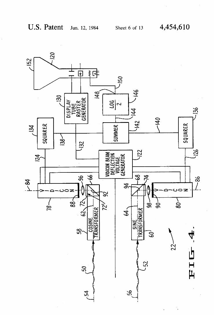
Referring now to FIG. 4, it will be seen that trans forming and enhancing circuit 22 comprises a “cosine transformer”, or noncoherent light Fourier optical co sine transformer, 58, and a “sine transformer” or nonco herent light Fourier optical sine transformer 60.
15
20
25
30
35
50
55
65
12 Such Fourier optical sine and cosine transformers for
use with coherent light are well-known to those having ordinary skill in the art. See, for example, U.S. Pat. No. 3,669,528, issued to John M. Richardson on June 13, 1972, and Chapter 5 of the Rogers text, cited supra, and the sources therein cited. As will be evident to those having ordinary skill in
the optical data processing art, other means than the means of FIG. 3 for providing input indicia image sig nals to Fourier optical transformers 58 and 60_of FIG. 4 may be provided by those having ordinary skill in that art without the exercise of invention. For example, it may be desirable to halt belt 24 twice
during the generation of each indicium spectrum, thus making it possible to successively expose the respective input portions of the Fourier optical transformers 58, 60 to indicium 40, employing the well-known storage property of the vidicon (80, FIG. 4), to retain the image derived from one Fourier optical transformer (60) until the image derived from the other (58) is picked up (by vidicon 78) when belt 24 halts for the second time. As seen in FIG. 4, the principal optical axis of Fourier
optical cosine transformer 58 is designated by the refer ence numeral 62, and the principal optical axis of Fou rier optical sine transformer 60 is designated by the reference numeral 64. As also indicated in FIG. 4, opti cal output axis 54 of beam splitter 46 (FIG. 3) is collin ear with optical axis 62 of cosine transformer 58, and optical output axis 56 of ' beam splitter 48 (FIG. 3) is collinear with optical axis 64 of sine transformer 60. As further seen in FIG. 4, a 90° deviating beam split
ter 66 is closely juxtaposed to the optical output end of cosine transformer 58, and a 90° deviating beam splitter 68 is closely juxtaposed to the optical output end of sine transformer 60. Since, as may be seen from FIG. 4, beam splitters 66 and 68, like beam splitters 46 and 48 (FIG. 3), serve only to deviate impingent light beams by 90°, the re?ecting surfaces of these beam splitters may be totally opaque, or prism or mirror arrangements may be substituted therefor. ,
Closely juxtaposed to the optical output surface of beam splitter 66 is an optical element 72 which will herein be called a “pixel averager”, and will be de scribed hereinbelow in connection with FIGS. 5A through 5C. Similarly, a substantially identical pixel averager 74 is closely juxtaposed to the optical output surface of beam splitter 68. As further seen in FIG. 4, a vidicon camera tube 78 is
located closely adjacent pixel averager 72, and a vid icon camera tube 80 is positioned closely adjacent pixel averager 74. Vidicon camera tube 78 has an axis of symmetry 84 which passes through the center of its photocathode, and vidicon camera tube 80 has an axis of symmetry 86, which passes though the center of its photocathode, both axis of symmetry 84 and axis of symmetry 86 being perpendicular to the photocathodes of their respective vidicon camera tubes.
Vidicon tube 78 may, in the well-known manner, be provided with an opaque mask 88 having a rectangular central opening which defines its picture format. When vidicon tube 78 is provided with such a mask 88, vid icon tube 80 will be provided with a similar mask 90, the rectangular openings in the masks 88 and 90 being of the same area and aspect ration and both of said rectangular openings being centered about the axes of symmetry 84, 86 of their respective vidicon tubes. Beam splitters 66 and 68 may be thought of as having
respective optical output axes 92 and 94. Optical output