8051 Overview and Instruction Set -...
28
1 Curt Nelson Engr355 8051 Overview and Instruction Set Curtis A. Nelson Engr 355 2 Curt Nelson Engr355 Microprocessors vs. Microcontrollers • Microprocessors are single-chip CPUs used in microcomputers • Microcontrollers and microprocessors are different in three main aspects: hardware architecture, applications, and instruction set features • Hardware architecture: A microprocessor is a single chip CPU while a microcontroller is a single IC contains a CPU and much of remaining circuitry of a complete computer (e.g., RAM, ROM, serial interface, parallel interface, timer, interrupt handling circuit) • Applications: Microprocessors are commonly used as a CPU in computers while microcontrollers are found in small, minimum component designs performing control oriented activities
Transcript of 8051 Overview and Instruction Set -...
1Curt Nelson Engr355
8051 Overview and Instruction Set
Curtis A. Nelson
Engr 355
2Curt Nelson Engr355
Microprocessors vs. Microcontrollers
• Microprocessors are single-chip CPUs used in microcomputers
• Microcontrollers and microprocessors are different in three main aspects: hardware architecture, applications, and instruction set features
• Hardware architecture: A microprocessor is a single chip CPU while a microcontroller is a single IC contains a CPU and much of remaining circuitry of a complete computer (e.g., RAM, ROM, serial interface, parallel interface, timer, interrupt handling circuit)
• Applications: Microprocessors are commonly used as a CPU in computers while microcontrollers are found in small, minimum component designs performing control oriented activities
3Curt Nelson Engr355
• Instruction set: – Microprocessor instruction sets are processing
intensive• Their instructions operate on nibbles, bytes, words, or
even double words.• Addressing modes provide access to large arrays of data
using pointers and offsets.– Microcontroller instruction sets cater to control of
inputs and outputs• They have instructions to set and clear individual bits and
perform bit operations.• They have instructions for input/output operations, event
timing, enabling and setting priority levels for interrupts caused by external stimuli.
• Processing power of a microcontroller is much less than a microprocessor.
Microprocessors vs. Microcontrollers
4Curt Nelson Engr355
8051
• Today over fifty companies produce variations of the 8051.
• Several of these companies have over fifty versions of the 8051.
• 8051 cores are available for implementations in FPGA’s or ASIC’s.
• Over 100 million 8051’s are sold each year.• The 8051 has been extremely successful, and has
directly influenced many of the more recent microcontroller architectures.
5Curt Nelson Engr355
MCS-51
• 8051 belongs to MCS-51 family of microcontrollers • MCS-51 was developed by Intel but other
manufacturers (e.g., Siemens, Philips) are second sources of this family.
• Summary of features of the standard 8051– 4K bytes internal ROM (program)– 128 bytes internal RAM (data)– Four 8-bit I/O ports– Two 16-bit timers– Serial interface– 64K external code memory space– 64K external data memory space– 210 bit-addressable locations
6Curt Nelson Engr355
Memory
• 8051 implements a separate memory space for programs (code) and data.
• Both code and data may be internal, however, both expand using external components to a maximum of 64K code memory and 64K data memory.
• Internal memory consists of on-chip ROM and on-chip data RAM.
• On-chip RAM contains a rich arrangement of general purpose storage, bit addressable storage, register banks, and special function registers.
• In the 8051, the registers and input/output ports are memory mapped and accessible like any other memory location.
• In the 8051, the stack resides within the internal RAM, rather than in external RAM.
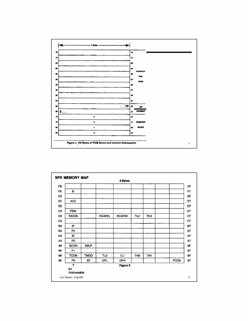
7Curt Nelson Engr355
8Curt Nelson Engr355
9Curt Nelson Engr355
10Curt Nelson Engr355
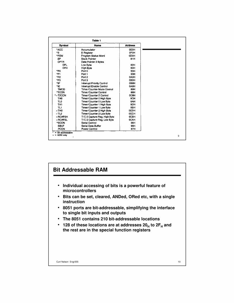
Bit Addressable RAM
• Individual accessing of bits is a powerful feature of microcontrollers
• Bits can be set, cleared, ANDed, ORed etc, with a single instruction
• 8051 ports are bit-addressable, simplifying the interface to single bit inputs and outputs
• The 8051 contains 210 bit-addressable locations• 128 of these locations are at addresses 20H to 2FH and
the rest are in the special function registers
11Curt Nelson Engr355
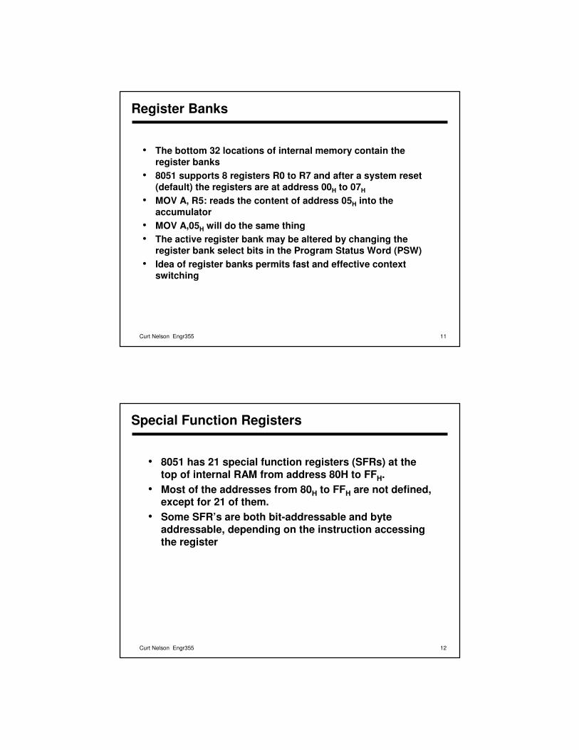
Register Banks
• The bottom 32 locations of internal memory contain the register banks
• 8051 supports 8 registers R0 to R7 and after a system reset (default) the registers are at address 00H to 07H
• MOV A, R5: reads the content of address 05H into the accumulator
• MOV A,05H will do the same thing• The active register bank may be altered by changing the
register bank select bits in the Program Status Word (PSW)• Idea of register banks permits fast and effective context
switching
12Curt Nelson Engr355
Special Function Registers
• 8051 has 21 special function registers (SFRs) at the top of internal RAM from address 80H to FFH.
• Most of the addresses from 80H to FFH are not defined, except for 21 of them.
• Some SFR’s are both bit-addressable and byte addressable, depending on the instruction accessing the register
13Curt Nelson Engr355
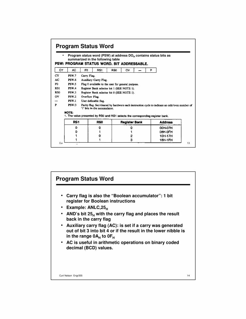
Program Status Word• Program status word (PSW) at address DOH contains status bits as
summarized in the following table
14Curt Nelson Engr355
Program Status Word
• Carry flag is also the “Boolean accumulator”: 1 bit register for Boolean instructions
• Example: ANLC,25H
• AND’s bit 25H with the carry flag and places the result back in the carry flag
• Auxiliary carry flag (AC): is set if a carry was generated out of bit 3 into bit 4 or if the result in the lower nibble is in the range 0AH to 0FH
• AC is useful in arithmetic operations on binary coded decimal (BCD) values.
15Curt Nelson Engr355
Program Status Word
• Flag 0 (F0): a general purpose flag bit available for user
• Register Bank Select Bits (RS0 and RS1): determine the active register bank
• Example: the following instructions enable register bank 3 and move the content of R7 (address 1FH) to the accumulator SETB RS1SETB RS0MOV A,R7
16Curt Nelson Engr355
Program Status Word
• Overflow flag (OV): is set after an addition or subtraction if there was an arithmetic overflow
• When signed numbers are added or subtracted this bit determines if the result is in the proper range
• Results greater than 127 or less than –128 will set OV bit• When unsigned numbers are added OV can be ignored• Example: What is the OV and the content of accumulator after
the following instruction sequence:MOV R7, #FFHMOV A, #0FH
ADD A,R7– Answer: OV=0, ACC=0EH
17Curt Nelson Engr355
Program Status Word
• Parity bit (p): is automatically set or cleared in each machine cycle to establish even parity in the accumulator
• Number of 1-bits in the accumulator plus P is always even
• P is used in serial port routines • What is the state of P after execution of the following
instruction?MOV A,#55H– Answer: P=0
18Curt Nelson Engr355
B Register
• B register or accumulator B at address F0H is used along with the accumulator for multiply and divide operations
• MUL AB: multiplies 8 bit unsigned values in A and B and leaves the 16 bit result in A (low byte) and B (high byte)
• DIV AB: divided A by B, leaving the integer result in A and remainder in B
• B register is bit-addressable
19Curt Nelson Engr355
Stack Pointer
• Stack pointer (SP) is an 8-bit register at address 81H
• It contains the address of the data item currently on top of thestack.
• Stack operations include pushing data on the stack and popping data off the stack
• Pushing increments SP before writing the data• Popping from the stack reads the data and decrements the SP• 8051 stack is kept in the internal RAM• Depending on the initial value of the SP, stack can have
different sizes• Example: MOV SP,#5FH
• On 8051 this would limit the stack to 32 bytes since the uppermost address of on chip RAM is 7FH.
20Curt Nelson Engr355
Stack and Data Pointers
• The default value of SP (after system reset) is 07H.• This result in the first stack write operation to store data in
location 08H which means that register bank 1 (and possible 2 and 3) are not available
• User may initialize the SP to avoid this• Data pointer (DPTR): is used to access external data or code• DPTR is a 16 bit register at addresses 82H (low byte) and 83H
(high byte)• Example: the following instructions write 55H into external
RAM location 1000H:MOV A,#55H
MOV DPTR,#1000H
MOVX @DPTR,A
21Curt Nelson Engr355
Instruction Set
• 8051 instructions have 8-bit opcode• There are 256 possible instructions of which 255 are
implemented• Some instructions have one or two additional bytes for
data or address• There are 139 1-byte instructions, 92 2-byte
instructions, and 24 3-byte instruction• Where does the data for an instruction come from?
– Addressing modes
22Curt Nelson Engr355
Addressing Modes
• There are eight addressing modes available in the 8051:– Register– Direct– Indirect– Immediate– Relative– Absolute– Long– Indexed
23Curt Nelson Engr355
Register Addressing
• 8051 has access to eight working registers (R0 to R7)• Instructions using register addressing are encoded using the
three least significant bits of the instruction opcode to specify a register
• Example: ADD A,R7• The opcode is 00101111. 00101 indicates the instruction and
the three lower bits, 111, specify the register• Some instructions are specific to a certain register, such as
the accumulator, data pointer etc.• Example: INC DPTR
– A 1-byte instruction adding 1 to the data pointer• Example: MUL AB
– A 1-byte instruction multiplying unsigned values in accumulator and register B
24Curt Nelson Engr355
Direct Addressing
• Direct addressing can access any on-chip memory location
• Example: ADD A,55H
• Example: MOV P1, A– Transfers the content of accumulator to Port 1 (address
90H)
25Curt Nelson Engr355
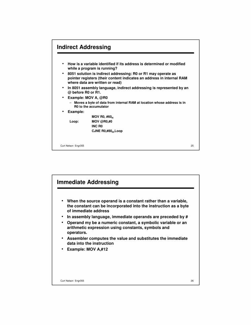
Indirect Addressing
• How is a variable identified if its address is determined or modified while a program is running?
• 8051 solution is indirect addressing: R0 or R1 may operate as pointer registers (their content indicates an address in internal RAM where data are written or read)
• In 8051 assembly language, indirect addressing is represented by an @ before R0 or R1.
• Example: MOV A, @R0– Moves a byte of data from internal RAM at location whose address is in
R0 to the accumulator
• Example: MOV R0, #60H
Loop: MOV @R0,#0INC R0CJNE R0,#80H,Loop
26Curt Nelson Engr355
Immediate Addressing
• When the source operand is a constant rather than a variable, the constant can be incorporated into the instruction as a byte of immediate address
• In assembly language, immediate operands are preceded by #• Operand my be a numeric constant, a symbolic variable or an
arithmetic expression using constants, symbols and operators.
• Assembler computes the value and substitutes the immediate data into the instruction
• Example: MOV A,#12
27Curt Nelson Engr355
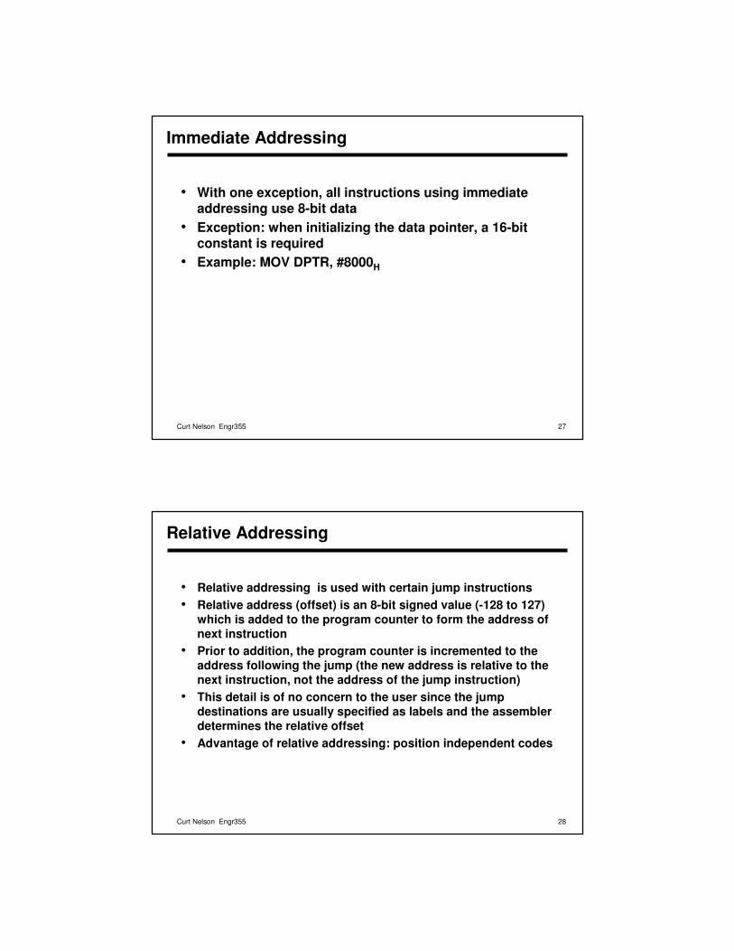
Immediate Addressing
• With one exception, all instructions using immediate addressing use 8-bit data
• Exception: when initializing the data pointer, a 16-bit constant is required
• Example: MOV DPTR, #8000H
28Curt Nelson Engr355
Relative Addressing
• Relative addressing is used with certain jump instructions• Relative address (offset) is an 8-bit signed value (-128 to 127)
which is added to the program counter to form the address of next instruction
• Prior to addition, the program counter is incremented to the address following the jump (the new address is relative to the next instruction, not the address of the jump instruction)
• This detail is of no concern to the user since the jump destinations are usually specified as labels and the assembler determines the relative offset
• Advantage of relative addressing: position independent codes
29Curt Nelson Engr355
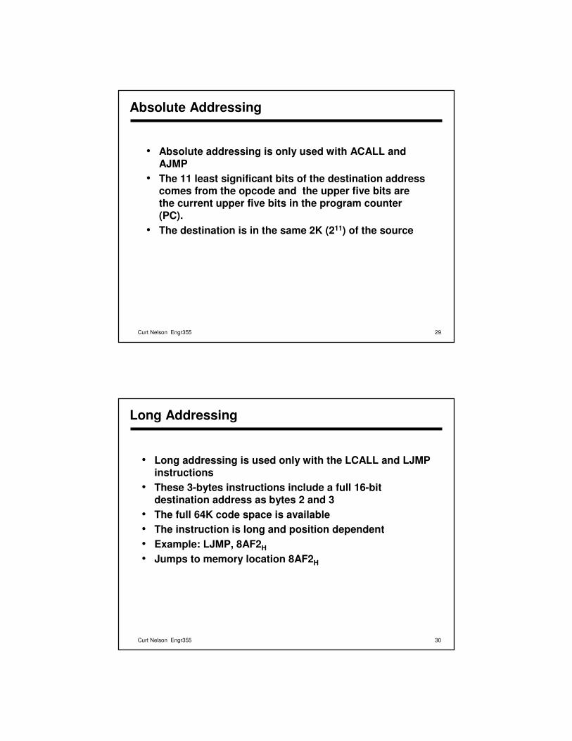
Absolute Addressing
• Absolute addressing is only used with ACALL and AJMP
• The 11 least significant bits of the destination address comes from the opcode and the upper five bits are the current upper five bits in the program counter (PC).
• The destination is in the same 2K (211) of the source
30Curt Nelson Engr355
Long Addressing
• Long addressing is used only with the LCALL and LJMP instructions
• These 3-bytes instructions include a full 16-bit destination address as bytes 2 and 3
• The full 64K code space is available• The instruction is long and position dependent• Example: LJMP, 8AF2H
• Jumps to memory location 8AF2H
31Curt Nelson Engr355
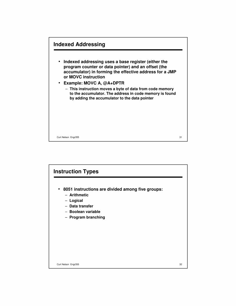
Indexed Addressing
• Indexed addressing uses a base register (either the program counter or data pointer) and an offset (the accumulator) in forming the effective address for a JMP or MOVC instruction
• Example: MOVC A, @A+DPTR– This instruction moves a byte of data from code memory
to the accumulator. The address in code memory is found by adding the accumulator to the data pointer
32Curt Nelson Engr355
Instruction Types
• 8051 instructions are divided among five groups:– Arithmetic– Logical– Data transfer– Boolean variable– Program branching
33Curt Nelson Engr355
Arithmetic
• Since different addressing modes are available, an arithmetic instruction may be written in different ways.
• Example: ADD A,7FH
ADD A,@R0ADD A,R7ADD A,#35H
• All arithmetic instructions are executed in one machine cycle except INC DPTR (two cycles) and MUL AB and DIV AB (four cycles)
34Curt Nelson Engr355
Arithmetic
• Example: accumulator contains 63H, R3 contains 23H, and the PSW contains 00H. What is the content of the accumulator and the PSW after execution of ADD A, R3 instruction?– Answer: ACC=86H, C=0, OV=1, P=1 PSW=00000101
• Example: write code that subtracts content of R6 from R7 and leave the result in R7MOV A,R7CLR CSUBB A, R6MOV R7,A– Clearing the flag is necessary because the only form of
subtraction in 8051 is SUBB (subtract with borrow). The operation subtracts from the accumulator source byte and carry bit.
35Curt Nelson Engr355
Arithmetic
• Any memory location can be incremented or decremented using direct addressing without going through the accumulator.
• Example: INC 7FH– Increments the value in memory location 7FH
• INC instruction can also work on 16-bit data pointer• A decrement data pointer is not provided and requires a
sequence of instructions:DEC DPLMOV R7,DPLCJNE R7, #FFH, SKIPDEC DPH
SKIP: (continue)
36Curt Nelson Engr355
Arithmetic
• MUL AB: multiplies 8 bit unsigned values in A and B and leaves the 16 bit result in A (low byte) and B (high byte). If the product is greater than 255 (FFH), overflow flag is set.
• Example: ACC=55H, B register contains 22H, and PSW=00H. What are the contents of these registers after execution of the MUL AB instruction?– Answer: ACC=4AH, B=0BH, P bit in PSW is set to one.
Since the result is greater than 255, overflow flag is set.• DIV AB: divided A by B, leaving the integer result in A
and remainder in B
37Curt Nelson Engr355
Arithmetic
• For BCD arithmetic, ADD and ADDC must be followed by a DA A (decimal adjust) operation to ensure the result is in range for BCD.– Note: ADDC simultaneously adds accumulator, the
variable and the carry flag.• Note that DA A will not convert a binary number to BCD• Example: If ACC contains BCD value of 59 then:
ADD A, #1DA A– First adds 1 to A, leaving 5A and then adjust the result to
correct BCD value 60.
38Curt Nelson Engr355
Arithmetic
• Example: Two 4-digit BCD numbers are in internal memory at locations 40H, 41H and 42H, 43H. The most significant digits are in locations 40H and 42H. Add them and store the BCD result in locations 40H and 41H.MOV A, 43H
ADD A, 41H
DA AMOV 41H, AMOV A, 42H
ADDC A, 40H
DA AMOV 40H,A– An example of multi-precision arithmetic
39Curt Nelson Engr355
Logical Instructions
• 8051 logical instructions perform Boolean operations on bytes of data on a bit-by-bit basis .
• Example: let’s assume A=00110101B. Instruction ANL A,#01010011B will leave 00010001 in accumulator
• Different modes for logical instructions:ANL A,55HANL A,@R0ANL A,R6ANL A,#33H
• Logical operations can be performed on any byte in internal memory without going through the accumulator
• Example: XRL P1,#FFH
• Eight bits in Port 1 are read, each bit exclusive ORed. The result is written back to Port 1.
40Curt Nelson Engr355
Logical Instructions
• Rotate instructions (RL A, RR A) shift the accumulator one bit to the left or right. For a left rotation, MSB rolls into LSB position. For a right rotation, LSB rolls into MSB position.
• RLC A and RRC A perform similar operations on concatenation of carry flag and accumulator.
• Example: A=00H and C=1. After RRC A, what will be in A and C?– A=80H and C=0
• SWAP A: exchanges high and low nibbles within accumulator
41Curt Nelson Engr355
Logical Instructions
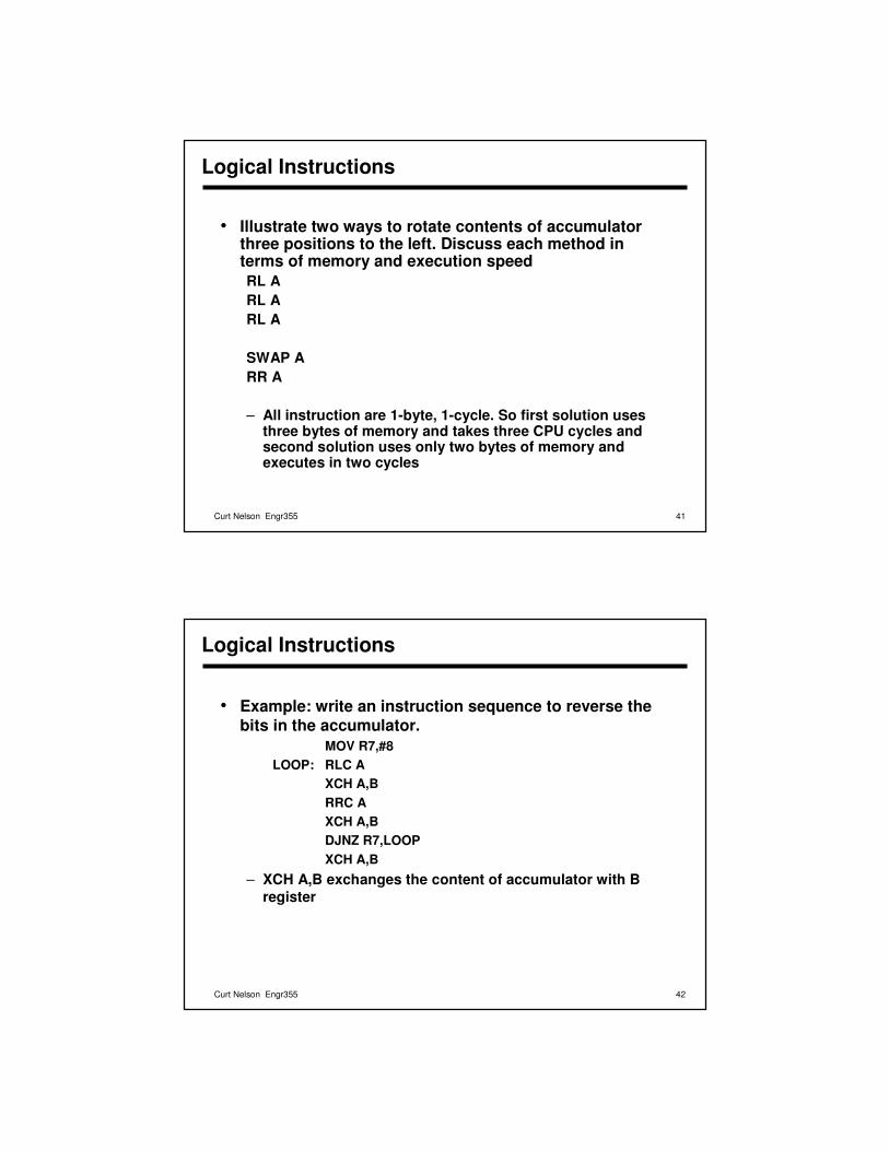
• Illustrate two ways to rotate contents of accumulator three positions to the left. Discuss each method in terms of memory and execution speedRL ARL ARL A
SWAP ARR A
– All instruction are 1-byte, 1-cycle. So first solution uses three bytes of memory and takes three CPU cycles and second solution uses only two bytes of memory and executes in two cycles
42Curt Nelson Engr355
Logical Instructions
• Example: write an instruction sequence to reverse the bits in the accumulator.
MOV R7,#8LOOP: RLC A
XCH A,BRRC AXCH A,BDJNZ R7,LOOPXCH A,B
– XCH A,B exchanges the content of accumulator with B register
43Curt Nelson Engr355
Data Transfer Instructions - Internal
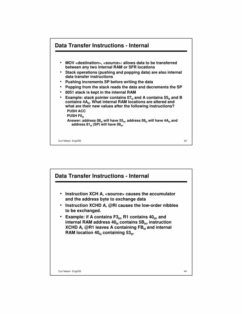
• MOV <destination>, <source>: allows data to be transferred between any two internal RAM or SFR locations
• Stack operations (pushing and popping data) are also internal data transfer instructions
• Pushing increments SP before writing the data• Popping from the stack reads the data and decrements the SP• 8051 stack is kept in the internal RAM• Example: stack pointer contains 07H and A contains 55H and B
contains 4AH. What internal RAM locations are altered and what are their new values after the following instructions?PUSH ACCPUSH F0H
Answer: address 08H will have 55H, address 09H will have 4AH and address 81H (SP) will have 09H.
44Curt Nelson Engr355
Data Transfer Instructions - Internal
• Instruction XCH A, <source> causes the accumulator and the address byte to exchange data
• Instruction XCHD A, @Ri causes the low-order nibbles to be exchanged.
• Example: if A contains F3H, R1 contains 40H, and internal RAM address 40H contains 5BH, instruction XCHD A, @R1 leaves A containing FBH and internal RAM location 40H containing 53H.
45Curt Nelson Engr355
Data Transfer Instructions - External
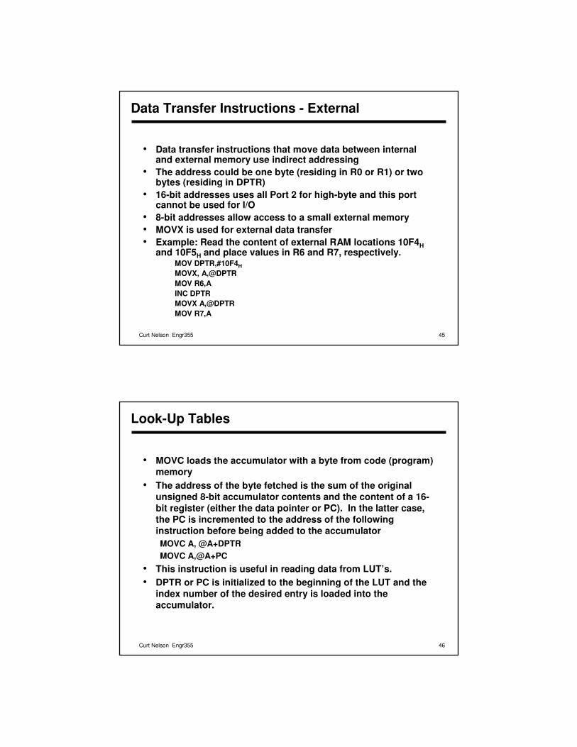
• Data transfer instructions that move data between internal and external memory use indirect addressing
• The address could be one byte (residing in R0 or R1) or two bytes (residing in DPTR)
• 16-bit addresses uses all Port 2 for high-byte and this port cannot be used for I/O
• 8-bit addresses allow access to a small external memory• MOVX is used for external data transfer• Example: Read the content of external RAM locations 10F4H
and 10F5H and place values in R6 and R7, respectively. MOV DPTR,#10F4HMOVX, A,@DPTRMOV R6,AINC DPTRMOVX A,@DPTRMOV R7,A
46Curt Nelson Engr355
Look-Up Tables
• MOVC loads the accumulator with a byte from code (program) memory
• The address of the byte fetched is the sum of the original unsigned 8-bit accumulator contents and the content of a 16-bit register (either the data pointer or PC). In the latter case, the PC is incremented to the address of the following instruction before being added to the accumulator MOVC A, @A+DPTRMOVC A,@A+PC
• This instruction is useful in reading data from LUT’s.• DPTR or PC is initialized to the beginning of the LUT and the
index number of the desired entry is loaded into the accumulator.
47Curt Nelson Engr355
Look-Up Tables
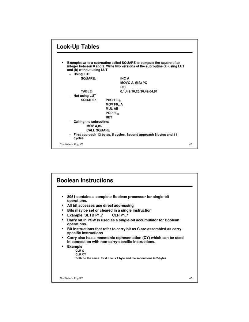
• Example: write a subroutine called SQUARE to compute the square of an integer between 0 and 9. Write two versions of the subroutine (a) using LUT and (b) without using LUT– Using LUT
SQUARE: INC AMOVC A, @A+PCRET
TABLE: 0,1,4,9,16,25,36,49,64,81– Not using LUT
SQUARE: PUSH F0HMOV F0H,AMUL ABPOP F0HRET
– Calling the subroutine: MOV A,#6CALL SQUARE
– First approach 13 bytes, 5 cycles. Second approach 8 bytes and 11 cycles
48Curt Nelson Engr355
Boolean Instructions
• 8051 contains a complete Boolean processor for single-bit operations.
• All bit accesses use direct addressing• Bits may be set or cleared in a single instruction• Example: SETB P1.7 CLR P1.7• Carry bit in PSW is used as a single-bit accumulator for Boolean
operations.• Bit instructions that refer to carry bit as C are assembled as carry-
specific instructions• Carry also has a mnemonic representation (CY) which can be used
in connection with non-carry-specific instructions.• Example:
CLR CCLR CYBoth do the same. First one is 1 byte and the second one is 2-bytes
49Curt Nelson Engr355
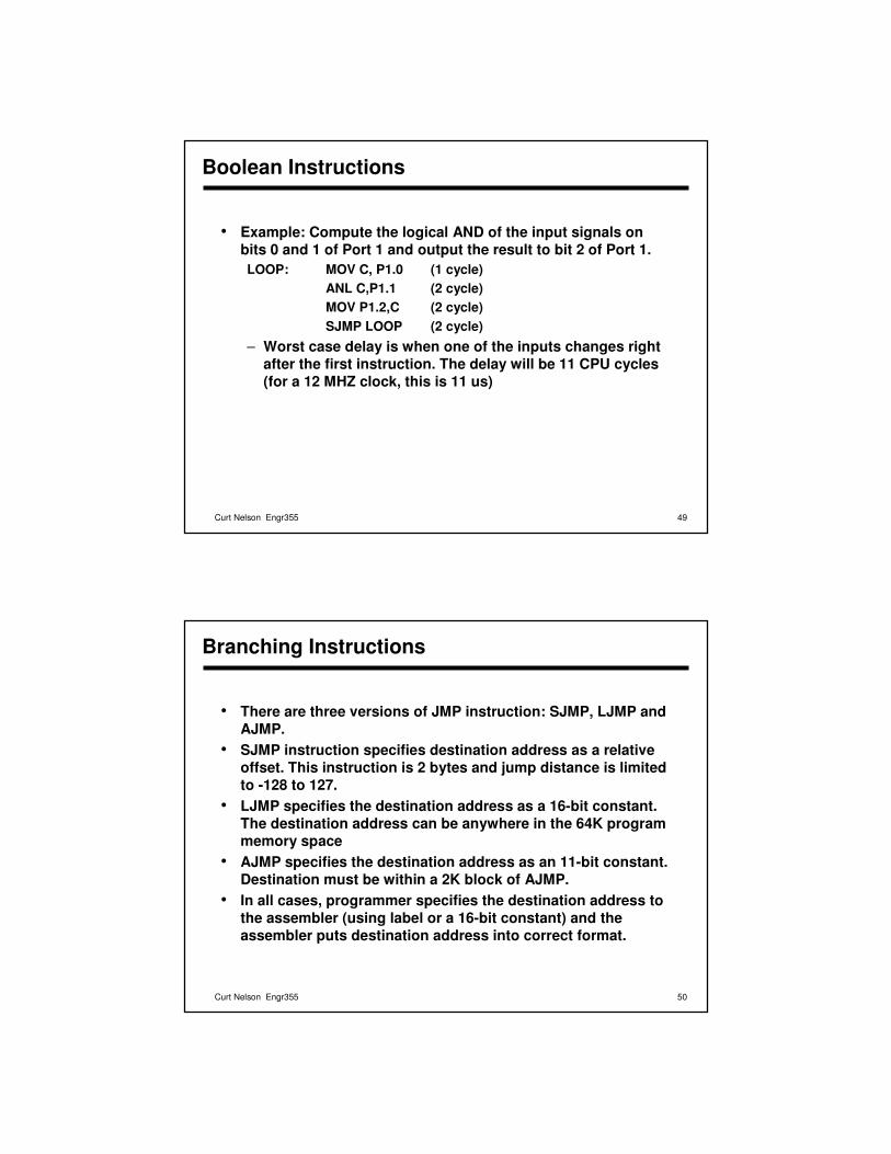
Boolean Instructions
• Example: Compute the logical AND of the input signals on bits 0 and 1 of Port 1 and output the result to bit 2 of Port 1.LOOP: MOV C, P1.0 (1 cycle)
ANL C,P1.1 (2 cycle)MOV P1.2,C (2 cycle)SJMP LOOP (2 cycle)
– Worst case delay is when one of the inputs changes right after the first instruction. The delay will be 11 CPU cycles (for a 12 MHZ clock, this is 11 us)
50Curt Nelson Engr355
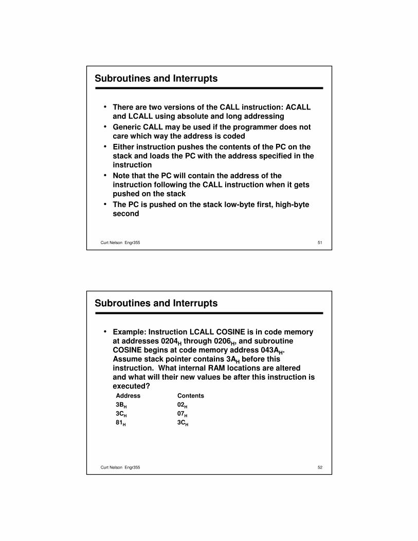
Branching Instructions
• There are three versions of JMP instruction: SJMP, LJMP and AJMP.
• SJMP instruction specifies destination address as a relative offset. This instruction is 2 bytes and jump distance is limitedto -128 to 127.
• LJMP specifies the destination address as a 16-bit constant. The destination address can be anywhere in the 64K program memory space
• AJMP specifies the destination address as an 11-bit constant. Destination must be within a 2K block of AJMP.
• In all cases, programmer specifies the destination address to the assembler (using label or a 16-bit constant) and the assembler puts destination address into correct format.
51Curt Nelson Engr355
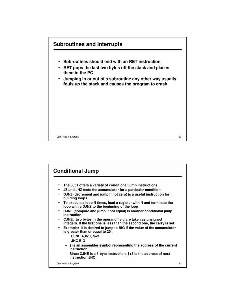
Subroutines and Interrupts
• There are two versions of the CALL instruction: ACALL and LCALL using absolute and long addressing
• Generic CALL may be used if the programmer does not care which way the address is coded
• Either instruction pushes the contents of the PC on the stack and loads the PC with the address specified in the instruction
• Note that the PC will contain the address of the instruction following the CALL instruction when it gets pushed on the stack
• The PC is pushed on the stack low-byte first, high-byte second
52Curt Nelson Engr355
Subroutines and Interrupts
• Example: Instruction LCALL COSINE is in code memory at addresses 0204H through 0206H, and subroutine COSINE begins at code memory address 043AH. Assume stack pointer contains 3AH before this instruction. What internal RAM locations are altered and what will their new values be after this instruction is executed?Address Contents3BH 02H
3CH 07H
81H 3CH
53Curt Nelson Engr355
Subroutines and Interrupts
• Subroutines should end with an RET instruction• RET pops the last two bytes off the stack and places
them in the PC• Jumping in or out of a subroutine any other way usually
fouls up the stack and causes the program to crash
54Curt Nelson Engr355
Conditional Jump
• The 8051 offers a variety of conditional jump instructions• JZ and JNZ tests the accumulator for a particular condition• DJNZ (decrement and jump if not zero) is a useful instruction for
building loops• To execute a loop N times, load a register with N and terminate the
loop with a DJNZ to the beginning of the loop• CJNE (compare and jump if not equal) is another conditional jump
instruction• CJNE: two bytes in the operand field are taken as unsigned
integers. If the first one is less than the second one, the carry is set• Example: It is desired to jump to BIG if the value of the accumulator
is greater than or equal to 20HCJNE A,#20H,$+3JNC BIG
– $ is an assembler symbol representing the address of the currentinstruction
– Since CJNE is a 3-byte instruction, $+3 is the address of next instruction JNC
55Curt Nelson Engr355
Summary
• 8051 overview• Hardware• Instruction set