8051 addressing modes
25
02/06/22 DPD 1 8051 Addressing Modes
-
Upload
ghoshshweta -
Category
Engineering
-
view
200 -
download
4
description
Transcript of 8051 addressing modes
04/10/23 DPD 1
8051 Addressing Modes

04/10/23 DPD 2
Introduction
• Immediate Addressing
• Register Addressing
• Direct Addressing
• Register Indirect Addressing
• Indexed Addressing

04/10/23 DPD 3
Immediate Addressing
• MOV A, #25H• MOV R4, #62• MOV B, #40H• MOV DTPR, #2550H
Same as
– MOV DPL, #50H
– MOV DPH, #25H

04/10/23 DPD 4
Register Addressing
• MOV A, R0• MOV R2, A• ADD A, R5• ADD A, R7• MOV R6, A
• MOV R4, R7 – invalid
• MOV DTPR, A – error
• MOV R7, DPL – valid• MOV R6, DPH – valid
04/10/23 DPD 5
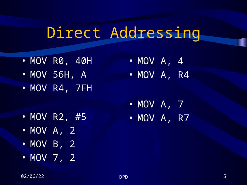
Direct Addressing
• MOV R0, 40H• MOV 56H, A• MOV R4, 7FH
• MOV R2, #5• MOV A, 2• MOV B, 2• MOV 7, 2
• MOV A, 4• MOV A, R4
• MOV A, 7• MOV A, R7

04/10/23 DPD 6
SFR registers and their addressing
• SFR – special function register
• A, B, PSW, DPTR can be addresses by– Names
– Addresses
• A – E0H• B – F0H
• MOV 0E0H, #55H• MOV A, #55H
• MOV 0F0H, #25H• MOV B, #25H
• MOV P1, A• MOV 90H, A

04/10/23 DPD 7
SFR …contd.
• SFR have addresses between 80H and FFH
• 00 to 7FH are addresses of RAM memory inside 8051
• Not all address spaces of 80 to FF is used by the SFR.
• Unused locations are reserved and must not be used by the 8051 programmer.
FFH
F0 – B register
E0 – Accumulator
D0 – PSW
B0 – Port 3
A0 – Port 2
90 – Port 1
83 – DPH
82 – DPL
81 – SP
80H 80 – Port 0

04/10/23 DPD 8
Stack and direct addressing
• PUSH A – invalid• PUSH 0E0H – valid
• PUSH 05• PUSH 06• PUSH 0E0H• PUSH 0F0H
• POP 02• POP 03

04/10/23 DPD 9
Register Indirect Addressing
• A register is used as a pointer to the data
• Only R0 and R1 are used for this purpose
• Must be preceded by ‘@’ sign
• MOV A, @R0– Move contents of
RAM location whose address is held by R0 into A
• MOV @R1, B– Move contents of B
into RAM location whose address is held by R1

04/10/23 DPD 10
Advantage of register indirect addressing
• Make accessing data dynamic rather than static
MOV A, #55H
MOV 40H, A
MOV 41H, A
MOV 42H, A
MOV 43H, A
MOV 44H, A
MOV A, #55HMOV R0, #40HMOV @R0, AINC R0MOV @R0, AINC R0MOV @R0, AINC R0MOV @R0, AINC R0MOV @R0, A
MOV A, #55H MOV R0, #40H MOV R2, #05AGAIN: MOV @R0, A INC R0 DJNZ R2, AGAIN
• Looping is not possible indirect addressing

04/10/23 DPD 11
Limitation of register indirect addressing
• Only R0 and R1 can be used for this purpose
• They 8 bit wide• Use is limited to internal RAM (30H –
7FH)• To access external RAM or on-chip ROM
we need 16-bit pointer– DPTR is used in this case
04/10/23 DPD 12
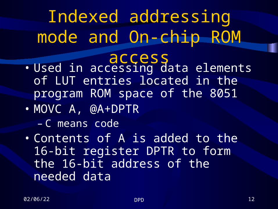
Indexed addressing mode and On-chip ROM access
• Used in accessing data elements of LUT entries located in the program ROM space of the 8051
• MOVC A, @A+DPTR– C means code
• Contents of A is added to the 16-bit register DPTR to form the 16-bit address of the needed data

04/10/23 DPD 13
Example
• Assume that the word ‘USA’ is burned into ROM location stating 200H, and that the program is burned into location stating at 0.
• Analyze how the program works and state where ‘USA’ is stored after this program is run.

04/10/23 DPD 14
Solution
ORG 0000HMOV DPTR, #200HCLR AMOVC A, @A+DPTRMOV R0, AINC DPTRCLR AMOVC A, @A+DPTRMOV R1, AINC DPTRCLR AMOVC A, @A+DPTRMOV R2, AHERE: SJMP HERE
ORG 200H
MYDATA: DB “USA”
END

04/10/23 DPD 15
Analysis• ROM location 200H – 202H have the following content
– 200 = (‘U’)– 201 = (‘S’)– 202 = (‘A’)
• Start with DPTR = 200H, and A = 0• MOVC A, @A+DPTR moves the content of ROM
location 200H (200H + 0 = 200H) to register A• Register A contains 55H, the ASCII value for ‘U’• This is moved to R0• Next DPTR is incremented to make DPTR = 201H

04/10/23 DPD 16
Example
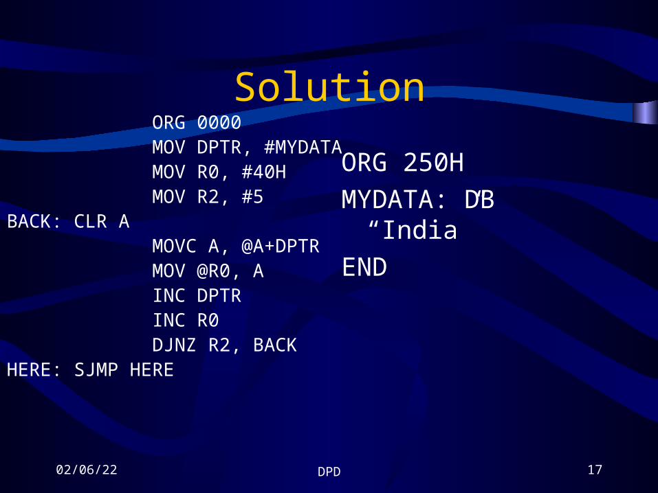
• Assuming that ROM space starting at 250H contains ‘India’
• Write a program to transfer the bytes into RAM locations stating at 40H
04/10/23 DPD 17
Solution ORG 0000 MOV DPTR, #MYDATA MOV R0, #40H MOV R2, #5BACK: CLR A MOVC A, @A+DPTR MOV @R0, A INC DPTR INC R0 DJNZ R2, BACKHERE: SJMP HERE
ORG 250H
MYDATA: DB “India”
END

04/10/23 DPD 18
Look-up table and MOVC ORG 0
MOV DPTR, #300H
MOV A, #0FFH
MOV P1, A
BACK: MOV A, P1
MOVC A, @A+DPTR
MOV P2, A
SJMP BACK
• Write a program to the x value from P1 and send x2 to P2 continuously
ORG 300HXSQR_TABLE:
DB 0, 1, 4, 9, 16, 25, 36, 49, 64, 81
END
300 = 00H 303 = 09H301 = 01H 304 = 10H302 = 04H 305 = 19H

04/10/23 DPD 19
Accessing RAM locations 30 – 7FH as scratch pad
• Write a program to toggle P1 a total of 200 times
• Use RAM location 32H to hold your counter value instead of registers R0 – R7
MOV P1, #55H
MOV 32H, #200
LOOP: CPL P1
ACALL DELAY
DJNZ 32H, LOOP

04/10/23 DPD 20
Bit-addressable RAM
• 16 bytes are bit-addressable
• 20H – 2FH
• Provides 16 x 8 = 128 bits
• Addressed as 0 to 127 or 00H to 7FH
• 20H – 2FH RAM location– Bit addressable
– Byte addressable
SETB 42H ;set bit 42H to 1
CLR 67H ;clear bit 67
CLR 0FH ;clear bit 0F
SETB 05

04/10/23 DPD 21
Single bit instruction
SETB bit bit =1
CLR bit bit = 0
CPL bit bit = NOT bit
JB bit, target Jump to target if bit = 1
JNB bit, target Jump to target if bit = 0
JBC bit, target Jump to target if bit = 1, clear bit

04/10/23 DPD 22
I/O port bit addresses
SETB 86H ;set bit P0.6
CLR 87H ;clear bit P0.7
04/10/23 DPD 23
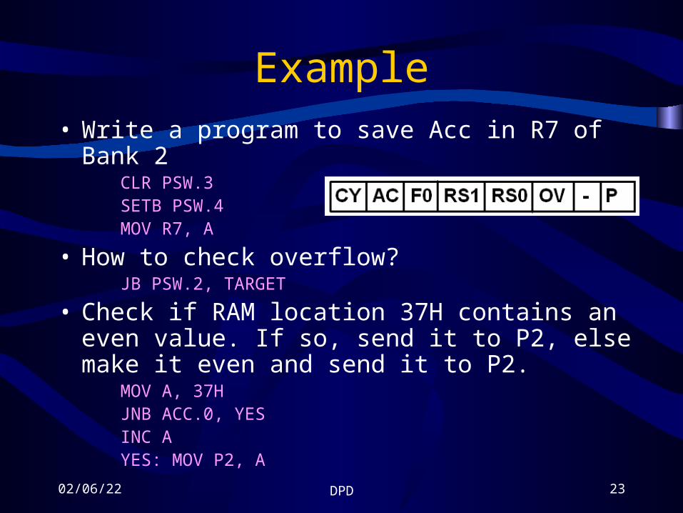
Example• Write a program to save Acc in R7 of Bank 2
CLR PSW.3SETB PSW.4MOV R7, A
• How to check overflow?JB PSW.2, TARGET
• Check if RAM location 37H contains an even value. If so, send it to P2, else make it even and send it to P2.
MOV A, 37HJNB ACC.0, YESINC AYES: MOV P2, A

04/10/23 DPD 24
Bit Directive
LED BIT P1.7
HERE: CPL LED
LCALL DELAY
SJMP HERE
SW BIT P1.7
LED BIT P2.0
HERE: MOV C, SW
MOV LED, C
SJMP HERE

04/10/23 DPD 25
Using EQU directive
• A switch is connected to pin P1.7
• Write a program to check that status of the switch and make the following decision– If SW = 0, send “No”
to P2– If SW = 1, send “Yes”
to P2
SW EQU P1.7MYDATA EQU P2
HERE: MOV C, SWJC OVERMOV MYDATA, #’N’MOV MYDATA, #’O’SJMP HERE
OVER: MOV MYDATA, #’Y’MOV MYDATA, #’Y’MOV MYDATA, #’Y’SJMP HEREEND