802.15.4 Media Access Controller (MAC) MyStarNetworkApp · 802.15.4 Media Access Controller (MAC)...
58
Document Number: 802154MSNAUG Rev. 1.6 2/2012 802.15.4 Media Access Controller (MAC) MyStarNetworkApp User’s Guide
-
Upload
truongduong -
Category
Documents
-
view
229 -
download
0
Transcript of 802.15.4 Media Access Controller (MAC) MyStarNetworkApp · 802.15.4 Media Access Controller (MAC)...
Document Number: 802154MSNAUGRev. 1.6
2/2012
802.15.4 Media Access Controller(MAC) MyStarNetworkApp
User’s Guide
How to Reach Us:
Home Page:www.freescale.com
E-mail:[email protected]
USA/Europe or Locations Not Listed:Freescale SemiconductorTechnical Information Center, CH3701300 N. Alma School RoadChandler, Arizona 85224+1-800-521-6274 or [email protected]
Europe, Middle East, and Africa:Freescale Halbleiter Deutschland GmbHTechnical Information CenterSchatzbogen 781829 Muenchen, Germany+44 1296 380 456 (English)+46 8 52200080 (English)+49 89 92103 559 (German)+33 1 69 35 48 48 (French)[email protected]
Japan:Freescale Semiconductor Japan Ltd.HeadquartersARCO Tower 15F1-8-1, Shimo-Meguro, Meguro-ku,Tokyo 153-0064, Japan0120 191014 or +81 3 5437 [email protected]
Asia/Pacific:Freescale Semiconductor Hong Kong Ltd.Technical Information Center2 Dai King StreetTai Po Industrial EstateTai Po, N.T., Hong Kong+800 2666 [email protected]
For Literature Requests Only:Freescale Semiconductor Literature Distribution CenterP.O. Box 5405Denver, Colorado 802171-800-521-6274 or 303-675-2140Fax: [email protected]
Information in this document is provided solely to enable system and software implementers to use Freescale Semiconductor products. There are no express or implied copyright licenses granted hereunder to design or fabricate any integrated circuits or integrated circuits based on the information in this document.
Freescale Semiconductor reserves the right to make changes without further notice to any products herein. Freescale Semiconductor makes no warranty, representation or guarantee regarding the suitability of its products for any particular purpose, nor does Freescale Semiconductor assume any liability arising out of the application or use of any product or circuit, and specifically disclaims any and all liability, including without limitation consequential or incidental damages. “Typical” parameters that may be provided in Freescale Semiconductor data sheets and/or specifications can and do vary in different applications and actual performance may vary over time. All operating parameters, including “Typicals”, must be validated for each customer application by customer’s technical experts. Freescale Semiconductor does not convey any license under its patent rights nor the rights of others. Freescale Semiconductor products are not designed, intended, or authorized for use as components in systems intended for surgical implant into the body, or other applications intended to support or sustain life, or for any other application in which the failure of the Freescale Semiconductor product could create a situation where personal injury or death may occur. Should Buyer purchase or use Freescale Semiconductor products for any such unintended or unauthorized application, Buyer shall indemnify and hold Freescale Semiconductor and its officers, employees, subsidiaries, affiliates, and distributors harmless against all claims, costs, damages, and expenses, and reasonable attorney fees arising out of, directly or indirectly, any claim of personal injury or death associated with such unintended or unauthorized use, even if such claim alleges that Freescale Semiconductor was negligent regarding the design or manufacture of the part.
Freescale™ and the Freescale logo are trademarks of Freescale Semiconductor, Inc. All other product or service names are the property of their respective owners.
© Freescale Semiconductor, Inc. 2006, 2007, 2008, 2009, 2010, 2011, 2012. All rights reserved.
802.15.4 Media Access Controller (MAC) MyStarNetworkApp User’s Guide, Rev. 1.6
Freescale Semiconductor iii
ContentsAbout This Book
Audience . . . . . . . . . . . . . . . . . . . . . . . . . . . . . . . . . . . . . . . . . . . . . . . . . . . . . . . . . . . . . . . . . . . . . vOrganization . . . . . . . . . . . . . . . . . . . . . . . . . . . . . . . . . . . . . . . . . . . . . . . . . . . . . . . . . . . . . . . . . . vRevision History . . . . . . . . . . . . . . . . . . . . . . . . . . . . . . . . . . . . . . . . . . . . . . . . . . . . . . . . . . . . . . . vDefinitions, Acronyms, and Abbreviations . . . . . . . . . . . . . . . . . . . . . . . . . . . . . . . . . . . . . . . . . viReferences. . . . . . . . . . . . . . . . . . . . . . . . . . . . . . . . . . . . . . . . . . . . . . . . . . . . . . . . . . . . . . . . . . . vi
Chapter 1 System Architecture
1.1 System Overview . . . . . . . . . . . . . . . . . . . . . . . . . . . . . . . . . . . . . . . . . . . . . . . . . . . . . . . . . . . . 1-11.2 Creating the Network . . . . . . . . . . . . . . . . . . . . . . . . . . . . . . . . . . . . . . . . . . . . . . . . . . . . . . . . . 1-21.3 Transferring Data . . . . . . . . . . . . . . . . . . . . . . . . . . . . . . . . . . . . . . . . . . . . . . . . . . . . . . . . . . . . 1-21.4 Monitoring Network Activity . . . . . . . . . . . . . . . . . . . . . . . . . . . . . . . . . . . . . . . . . . . . . . . . . . . 1-21.5 Use Cases . . . . . . . . . . . . . . . . . . . . . . . . . . . . . . . . . . . . . . . . . . . . . . . . . . . . . . . . . . . . . . . . . . 1-31.5.1 Running the End Devices in Autonomous Mode . . . . . . . . . . . . . . . . . . . . . . . . . . . . . . . . . 1-31.5.2 Monitoring Messages Using the Serial Port . . . . . . . . . . . . . . . . . . . . . . . . . . . . . . . . . . . . . 1-4
Chapter 2 Software Implementation
2.1 Understanding the PAN Coordinator . . . . . . . . . . . . . . . . . . . . . . . . . . . . . . . . . . . . . . . . . . . . . 2-12.1.1 Coordinator Initialization . . . . . . . . . . . . . . . . . . . . . . . . . . . . . . . . . . . . . . . . . . . . . . . . . . . 2-12.1.2 Coordinator Energy Detection (ED) Scan Overview . . . . . . . . . . . . . . . . . . . . . . . . . . . . . . 2-32.1.3 Coordinator Short Address Assignment . . . . . . . . . . . . . . . . . . . . . . . . . . . . . . . . . . . . . . . . 2-62.1.4 Coordinator PAN ID Selection . . . . . . . . . . . . . . . . . . . . . . . . . . . . . . . . . . . . . . . . . . . . . . . 2-72.1.5 Coordinator PAN Startup . . . . . . . . . . . . . . . . . . . . . . . . . . . . . . . . . . . . . . . . . . . . . . . . . . . 2-72.1.6 Coordinator End Device Acceptance . . . . . . . . . . . . . . . . . . . . . . . . . . . . . . . . . . . . . . . . . 2-102.1.7 Sending Data to the End Devices . . . . . . . . . . . . . . . . . . . . . . . . . . . . . . . . . . . . . . . . . . . . 2-102.2 Understanding The Purger . . . . . . . . . . . . . . . . . . . . . . . . . . . . . . . . . . . . . . . . . . . . . . . . . . . . 2-122.2.1 Purger Initialization . . . . . . . . . . . . . . . . . . . . . . . . . . . . . . . . . . . . . . . . . . . . . . . . . . . . . . 2-132.2.2 Purger Tracking Function . . . . . . . . . . . . . . . . . . . . . . . . . . . . . . . . . . . . . . . . . . . . . . . . . . 2-132.2.3 Purger Check Function . . . . . . . . . . . . . . . . . . . . . . . . . . . . . . . . . . . . . . . . . . . . . . . . . . . . 2-132.2.4 Purger Remove Function . . . . . . . . . . . . . . . . . . . . . . . . . . . . . . . . . . . . . . . . . . . . . . . . . . 2-142.3 Understanding End Devices . . . . . . . . . . . . . . . . . . . . . . . . . . . . . . . . . . . . . . . . . . . . . . . . . . . 2-152.3.1 Finding the PAN . . . . . . . . . . . . . . . . . . . . . . . . . . . . . . . . . . . . . . . . . . . . . . . . . . . . . . . . . 2-162.3.2 Associating to the PAN. . . . . . . . . . . . . . . . . . . . . . . . . . . . . . . . . . . . . . . . . . . . . . . . . . . . 2-182.3.3 Receiving Data From the Coordinator . . . . . . . . . . . . . . . . . . . . . . . . . . . . . . . . . . . . . . . . 2-212.3.4 Sending Data to Coordinator . . . . . . . . . . . . . . . . . . . . . . . . . . . . . . . . . . . . . . . . . . . . . . . 2-222.3.5 End Device Low Power Mode Overview . . . . . . . . . . . . . . . . . . . . . . . . . . . . . . . . . . . . . . 2-23

802.15.4 Media Access Controller (MAC) MyStarNetworkApp User’s Guide, Rev. 1.6
iv Freescale Semiconductor
Appendix A MC1322x Functionality
A.1 Overview. . . . . . . . . . . . . . . . . . . . . . . . . . . . . . . . . . . . . . . . . . . . . . . . . . . . . . . . . . . . . . . . . . . A-1A.2 Coordinator . . . . . . . . . . . . . . . . . . . . . . . . . . . . . . . . . . . . . . . . . . . . . . . . . . . . . . . . . . . . . . . . . A-1A.3 End Device . . . . . . . . . . . . . . . . . . . . . . . . . . . . . . . . . . . . . . . . . . . . . . . . . . . . . . . . . . . . . . . . . A-3
Appendix B MyStarNetwork Demonstration GUI User’s Guide
B.1 Installing MyStarNetwork Demonstration GUI . . . . . . . . . . . . . . . . . . . . . . . . . . . . . . . . . . . . . B-1B.2 GUI Requirements . . . . . . . . . . . . . . . . . . . . . . . . . . . . . . . . . . . . . . . . . . . . . . . . . . . . . . . . . . . B-1B.3 Embedded Applications Requirements. . . . . . . . . . . . . . . . . . . . . . . . . . . . . . . . . . . . . . . . . . . . B-1B.4 Restoring the MyStarNetwork Embedded Applications to a Board. . . . . . . . . . . . . . . . . . . . . . B-2B.4.1 Creating the BeeKit Solution . . . . . . . . . . . . . . . . . . . . . . . . . . . . . . . . . . . . . . . . . . . . . . . . B-2B.4.2 Using IAR Embedded Workbench to Compile and Load Images . . . . . . . . . . . . . . . . . . . . B-5B.4.3 Using CodeWarrior Development Suite for Microcontrollers to Compile and Load Images . .
B-6B.5 Running the MyStarNetwork Demonstration . . . . . . . . . . . . . . . . . . . . . . . . . . . . . . . . . . . . . . . B-7B.5.1 Starting the Demonstration and Creating the PAN. . . . . . . . . . . . . . . . . . . . . . . . . . . . . . . . B-7B.5.2 Monitoring Sensor Data Reports . . . . . . . . . . . . . . . . . . . . . . . . . . . . . . . . . . . . . . . . . . . . B-11B.6 MyStarNetwork Demonstration GUI User Interface Overview . . . . . . . . . . . . . . . . . . . . . . . . B-13B.6.1 Application Toolbar . . . . . . . . . . . . . . . . . . . . . . . . . . . . . . . . . . . . . . . . . . . . . . . . . . . . . . B-13B.6.2 Serial Port Connections Panel. . . . . . . . . . . . . . . . . . . . . . . . . . . . . . . . . . . . . . . . . . . . . . . B-13B.6.3 MyStarNetwork Main Panel . . . . . . . . . . . . . . . . . . . . . . . . . . . . . . . . . . . . . . . . . . . . . . . . B-14B.6.4 MyStarNetwork Nodes Panel . . . . . . . . . . . . . . . . . . . . . . . . . . . . . . . . . . . . . . . . . . . . . . . B-15B.6.5 MyStarNetwork Log Panel . . . . . . . . . . . . . . . . . . . . . . . . . . . . . . . . . . . . . . . . . . . . . . . . . B-15B.6.6 MyStarNetwork Settings Dialog. . . . . . . . . . . . . . . . . . . . . . . . . . . . . . . . . . . . . . . . . . . . . B-15

802.15.4 Media Access Controller (MAC) MyStarNetworkApp User’s Guide, Rev. 1.6
Freescale Semiconductor v
About This BookThis guide provides information about creation and maintenance of non-beacon star networks based on the Freescale 802.15.4 Media Access Controller (MAC) implementation. The MyStarNetworkApp is a set of two (2) applications created on top of 802.15.4 Media Access Controller (MAC). These demonstration applications currently run on the following Freescale boards:
• 13213 Network Controller Board (NCB)
• 13213 Sensor Reference Board (SRB)
• 1322x Network Node
• 1322x Sensor Node
• 13192-EVB
• 13192 Sensor Applications Reference Design (SARD) Board
• 1320x-QE128-EVB Board
The examples used in this document use the NCB and SRB only unless otherwise noted.
Audience
This document is intended for application developers building 802.15.4/ZigBee applications.
Organization
This document is organized into 2 chapters.
Chapter 1 System Architecture — Describes the hardware architecture of the MyStarNetworkApp and guides users through the required steps for starting the network and performing various operations.
Chapter 2 Software Implementation — Describes the software implementation of the Coordinator, the Purger, and the End Device.
Appendix A MC1322x Functionality — Describes the differences between the MyStarNetwork implementations for HCS08 and MC1322x ARM7 based platforms.
Appendix B MC1322x MyStarNetwork Demo PC Application User’s Guide — Describes the MyStarNetwork Demonstration application for the MC1322x Graphical User Interface (GUI) front-end which displays wireless node network activity.
Revision History
The following table summarizes revisions to this document since the previous release (Rev. 1.4).
Revision History
Location Revision
Entire Document Updated for MC1322x silicon revision.

802.15.4 Media Access Controller (MAC) MyStarNetworkApp User’s Guide, Rev. 1.6
vi Freescale Semiconductor
Definitions, Acronyms, and Abbreviations
The following list defines the acronyms and abbreviations used in this document.
BDM debugger A debugger using the BDM interface for communication with the MCU. An example is the P&E BDM Multilink debugger for HCS08.
BDM Background Debug Module
EVB Evaluation Board
EVK Evaluation Kit
FFD Full Function Device (Coordinator)
GUI Graphical User Interface
MAC Medium Access Control
MCU MicroController Unit
NVM None-Volatile Memory
PC Personal Computer
PCB Printed Circuit Board
RFD Reduced Function Device (End Device)
References
The following sources were referenced to produce this book:
[1] IEEE Computer Society, IEEE Std 802.15.4™-2003, May 12th 2003
[2] 802.15.4 MAC/PHY Software Reference Manual, 802154MPSRM, Freescale Semiconductor, 2004, 2005, 2006
[3] 802.15.4 MAC MyWirelessApp User's Guide, 802154MWAUG, revision 1.1, Freescale Semiconductor, September 2007
[4] BeeKit Wireless Connectivity Toolkit User’s Guide (BKWCTKUG), revision 1.0, March 2007

802.15.4 Media Access Controller (MAC) MyStarNetworkApp User’s Guide, Rev. 1.6
Freescale Semiconductor 1-1
Chapter 1 System ArchitectureThis chapter describes the hardware architecture of the MyStarNetworkApp and guides users through the required steps for starting the network and performing various operations.
NOTE
The examples as shown in this guide use the NCB as the PAN Coordinator and one to four SRBs as End Devices. The MyStarNetworkApp will also run on the 13192-EVB as the PAN Coordinator and one to four SARDs as End Devices.
For more information on the 13192-EVB, refer to the 13193 Evaluation Board Development Kit (13193EVB) User’s Guide (13193EVBUG). For more information on the SARD, refer to the Sensor Applications Reference Design User’s Guide (MC13192SARDUG). For more information on the SRB and NCB, refer to the 13213 Evaluation Kits User’s Guide (13213EVKUG).
The MyStarNetworkApp source code example applications include the Freescale MAC library version 2.01 and later. The demonstration applications are included in MAC HCS08 Codebase, starting with the first release, BeeKit MAC Codebase 1.0.0 and continuing with the second release, BeeKit HCS08 MAC Codebase 1.0.1. Updates for the Codebase and for applications can be downloaded from the Freescale ZigBee site: http://www.freescale.com/zigbee
1.1 System Overview
System setup consists of one PAN Coordinator and one to four End Devices as shown in Figure 1-1. The devices in this example use the NCB as a Coordinator and SRBs as the End Devices. Users can extend the MyStarNetworkApp by turning on more than one End Device. The MyStarNetworkApp supports up to four (4) End Devices. The serial connections with PCs are for displaying different status messages and for sending text messages to the devices in the network. The serial connections are optional because the network can function in autonomous mode.
Figure 1-1. MyStartNetworkApp
UART IFUART IF
OPTIONAL:PC with terminal
program
OPTIONAL:PC with terminal
program
OPTIONAL:PC with terminal
program
PAN
Coordinator
End Device 1
End Device 4
.
.
.
System Architecture
802.15.4 Media Access Controller (MAC) MyStarNetworkApp User’s Guide, Rev. 1.6
1-2 Freescale Semiconductor
1.2 Creating the Network
Create the network by powering on the boards. One of the boards must be running the PAN Coordinator firmware. After power-up, a switch (SW1 to SW4 for NCB; S1 to S4 for EVB) must be pressed in order to start the PAN Coordinator. When the starting phase is finished, the PAN Coordinator prints the following messages about the characteristics of the network:
• RF channel used
• PAN ID
• Short address
The PAN Coordinator also prints a message every time an End Device associates.
The End Device prints the following messages when it successfully associates to the PAN Coordinator:
• PAN Coordinator address
• PAND ID
• RF channel
• Beacon information
• Link Quality Indicator (LQI)
• Short address received
Data can be exchanged after the first End Device is associated to the PAN Coordinator. The network dynamically extends when new End Devices are associated.
1.3 Transferring Data
When receiving UART data from the terminal console, the PAN Coordinator queues indirect packets for each End Device. This sets a relatively low natural restriction on the number of End Devices because the number of indirect buffers in the MAC is limited.
Packets are dropped in the event of a full indirect queue. The system alerts users about this event by printing a message in the PAN Coordinator console.
1.4 Monitoring Network Activity
User interaction with the MyStarNetworkApp takes place through a terminal console connected to the PAN Coordinator and the End Device UART ports. Messages typed in the terminal console connected to the PAN Coordinator are transmitted to all End Devices. The message is understood as a sequence of characters delimited by typing a carriage return, or a maximum of 20 characters. Due to the power-saving features enabled on the End Device MCU (STOP3 Mode) from the End Device to the PAN Coordinator, only a pre-defined message is sent when users press a button on the board.
Messages received by the Coordinator are displayed on the terminal console using the following format:
Device address [Device address] ([Link quality]): [received characters]
Messages received by the End Device are displayed on the terminal console using the following format:
PAN Coordinator ([Link quality]): [received characters]

System Architecture
802.15.4 Media Access Controller (MAC) MyStarNetworkApp User’s Guide, Rev. 1.6
Freescale Semiconductor 1-3
MyStarNetworkApp users can monitor network activity even though no terminals are connected to the participants in the network by using a network sniffer on the network channel. Besides the devices regularly polling the Coordinator for data, the PAN Coordinator sends a timer value every mDefaultValueOfTimeInterval_c seconds to all End Devices, where mDefaultValueOfTimeInterval_c is the value of the Basic time interval property from the Star Network Demo (Coordinator) project in BeeKit. This value appears in binary format on the LEDs on the boards serving as the End Device. The LEDs on the board serving as the PAN Coordinator reflect the number of End Devices connected to the network.
1.5 Use Cases
There are two possible use cases for employing the MyStarNetworkApp.
1. An autonomous network. The messages exchanged at the MAC level can be monitored using a network sniffer.
2. Users connect the PAN Coordinator and the End Devices to a computer through serial links. In this case, a Hyper Terminal style program is used for watching the messages that the devices output to the UART interface.
1.5.1 Running the End Devices in Autonomous Mode
To run the end devices in autonomous mode, perform the following steps:
1. Plug in the PAN Coordinator and the End Devices. Use an external adapter DC voltage adapter or the power the devices through the USB port of the computer.
2. Turn on the PAN Coordinator and press any of the four switches on the board.
3. The PAN Coordinator creates and starts up the PAN. At this point, the LEDs on this board should be off to indicate that there are no devices connected.
4. Turn on the first End Device and press any of the four switches on the board.
5. The End Devices connect to the PAN and is ready to receive messages from its Coordinator. At this time, the LEDs on the PAN Coordinator display as follows:
This LED configuration indicates that the first available address has been allocated to the new connected End Device.
6. Repeat the Steps 1 through 5 for the second End Device. When it associates to the PAN, the LEDs on the PAN Coordinator display as follows:
Users can add up to four (4) End Devices to the PAN. When the PAN is full, all the LED's on the Coordinator device are on.
Every mDefaultValueOfTimeInterval_c seconds, the Coordinator sends the value of an internal counter to all of the End Devices currently associated to the PAN. The LEDs on each End Device show the current value (in binary) received from the Coordinator.
System Architecture
802.15.4 Media Access Controller (MAC) MyStarNetworkApp User’s Guide, Rev. 1.6
1-4 Freescale Semiconductor
1.5.2 Monitoring Messages Using the Serial Port
Both the Coordinator and End Devices output messages to the serial port. In order to monitor these messages, the boards must be connected to a PC through the serial interface.
NOTE
Before proceeding, ensure that a Hyper Terminal style program is properly configured.
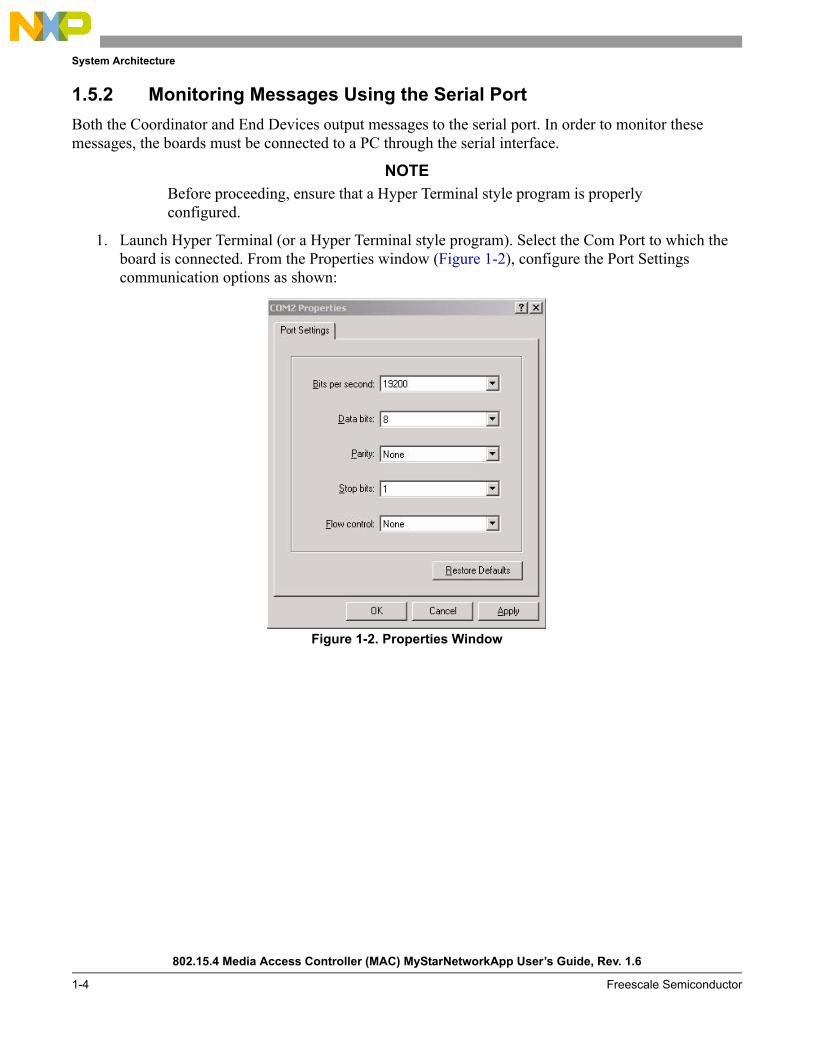
1. Launch Hyper Terminal (or a Hyper Terminal style program). Select the Com Port to which the board is connected. From the Properties window (Figure 1-2), configure the Port Settings communication options as shown:
Figure 1-2. Properties Window
System Architecture
802.15.4 Media Access Controller (MAC) MyStarNetworkApp User’s Guide, Rev. 1.6
Freescale Semiconductor 1-5
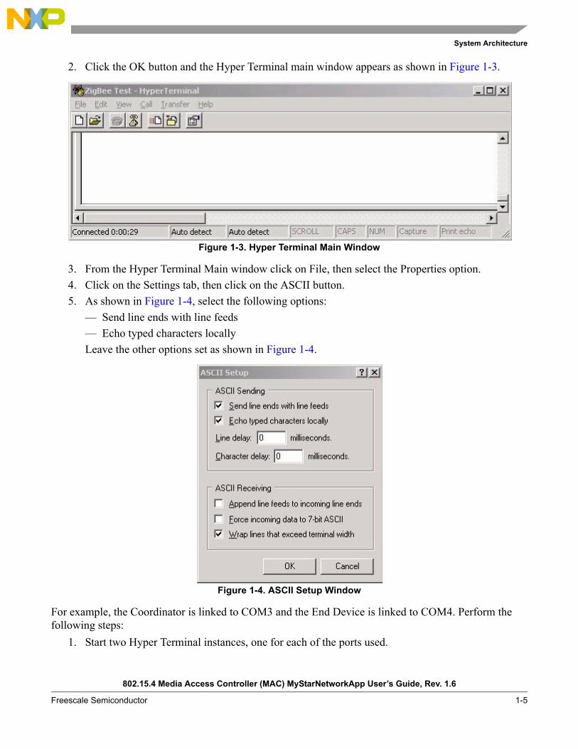
2. Click the OK button and the Hyper Terminal main window appears as shown in Figure 1-3.
Figure 1-3. Hyper Terminal Main Window
3. From the Hyper Terminal Main window click on File, then select the Properties option.
4. Click on the Settings tab, then click on the ASCII button.
5. As shown in Figure 1-4, select the following options:
— Send line ends with line feeds
— Echo typed characters locally
Leave the other options set as shown in Figure 1-4.
Figure 1-4. ASCII Setup Window
For example, the Coordinator is linked to COM3 and the End Device is linked to COM4. Perform the following steps:
1. Start two Hyper Terminal instances, one for each of the ports used.

System Architecture
802.15.4 Media Access Controller (MAC) MyStarNetworkApp User’s Guide, Rev. 1.6
1-6 Freescale Semiconductor
2. Turn on the Coordinator. The Hyper Terminal assigned to COM3 outputs the following message:
Press any switch on board to start running the application.
3. After pressing a switch on the Coordinator board, Hyper Terminal will output the following messages, assuming that the PAN uses the first channel in the 2.4 GHz band (channel no. 11):
The MyStarNetworkDemo application is initialized and ready.Initiating the Energy Detection Scan.Sending the MLME-Scan Request message to the MAC... Done.Received the MLME-Scan Confirm message from the MAC.ED scan returned the following results:[00 00 00 00 00 00 00 00 2C B0 00 10 10 10 00 00].Based on the ED scan the logical channel 0x0B was selected.Starting as PAN coordinator on channel 0x0B.PAN Coordinator started.Sending the MLME-Start Request message to the MAC... Done.Started the coordinator with PAN ID 0xBEEF, and short address 0xCAFE.Ready to send and receive data over the UART.
4. Turn on the End Device. The appropriate Hyper Terminal window outputs the following message:
Press any switch on board to start running the application.
5. After pressing a switch on the End Device board, and after it has connected to the PAN (the short address 1 has been assigned by the Coordinator), the appropriate Hyper Terminal window shows a message similar to the following (some values may be different):
Found a coordinator with the following properties:Address. . . . . . . 0xCAFEPAN ID. . . . . . . . 0xBEEFLogical Channel. . . .0x0BBeacon Spec. . . . . .0xCFFFLink Quality. . . . . 0x52
6. Go to the Hyper Terminal session assigned to COM3 (the one connected to the Coordinator) and type some text in the window and press Enter. The typed in text is sent through the UART to the Coordinator. The Coordinator forwards it through the PAN to the End Device. The text received from the Coordinator is displayed by the End Device to the UART (check the output of COM4 in the corresponding Hyper Terminal window). If there are more devices associated to the PAN, all of them receive the same message.
7. Press one of the four buttons on the End Device. The Coordinator receives a Pre-defined Message which outputs to COM3 of the PC.
8. Turn off the End Device. The Coordinator detects that the End Device has left the network (even if it hasn't sent the MLME-DISASSOCIATION.request primitive), by looking for devices that haven't received their packets. In this case, the Coordinator removes the End Device from the queue of associated devices and it outputs the following message:
Disconnected device: 01

802.15.4 Media Access Controller (MAC) MyStarNetworkApp User’s Guide, Rev. 1.6
Freescale Semiconductor 2-1
Chapter 2 Software ImplementationThis chapter describes the software implementation of the Coordinator, the Purger and the End Device. For more consistency, the code has been developed based on the 802.15.4 MAC MyWirelessApp application set. Freescale recommends that users refer to the MyWirelessApp documentation available from the www.freescale.com/zigbee web site as needed.
Each Star Network Demonstration represents a separate project in the MAC HCS08 Codebase. Source files for each MyStarNetwork application are found after exporting each project from BeeKit, at the following path:..\Project name\Application\Source
Where Project name is the name of the BeeKit project (i.e. Star Network Demonstration (Coordinator) or Star Network Demonstration (End Device)).
The Star Network Demonstration projects are generated from Freescale BeeKit, which allows users create, modify and update applications created on top of different Freescale frameworks, including Simple Media Access Controller (SMAC), 802.15.4 MAC and Freescale BeeStack. For more information on how to create wireless applications using BeeKit, refer to the BeeKit Wireless Connectivity Toolkit User’s Guide (BKWCTKUG).
2.1 Understanding the PAN Coordinator
On the PAN Coordinator, the application is implemented in the MApp.c file from the Star Network Demonstration (Coordinator) project.
2.1.1 Coordinator Initialization
The Coordinator initialization is done in the MApp_init function shown in the following code example:void MApp_init(void){ /* The initial application state */ gState = stateInit;
/* Initialize the MAC 802.15.4 extended address */ Init_MacExtendedAddress();
mSoftTimerId_c = TMR_AllocateTimer();
/* Register keyboard callback function */ KBD_Init(App_HandleKeys);
/* Initialize LCD Module */

Software Implementation
802.15.4 Media Access Controller (MAC) MyStarNetworkApp User’s Guide, Rev. 1.6
2-2 Freescale Semiconductor
LCD_Init(); /* initialize LED Module */ LED_Init();
/* Initialize the LPM module */ PWRLib_Init(); /* Initialize the UART so that we can print out status messages */ UartX_SetBaud(gUartDefaultBaud_c); UartX_SetRxCallBack(UartRxCallBack); /* initialize buzzer (NCB, SRB only) */ BuzzerInit(); /* Initialize purger module. */ Purger_Init( mExpireInterval_c, App_RemoveDevice);
/* Prepare input queues.*/ MSG_InitQueue(&mMlmeNwkInputQueue); MSG_InitQueue(&mMcpsNwkInputQueue);
/* Enable MCU interrupts */ IrqControlLib_EnableAllIrqs(); /*signal app ready*/ Led1Flashing(); Led2Flashing(); Led3Flashing(); Led4Flashing(); UartUtil_Print("\n\rPress any switch on board to start running the application.\n\r", gAllowToBlock_d); LCD_ClearDisplay(); LCD_WriteString(1,"Press any key"); LCD_WriteString(2,"to start."); }
The MApp_init function is called in the main function. The Init_802_15_4() is called in main, before calling the MApp_init function.
Before the Freescale IEEE 802.15.4 MAC layer can be accessed, it must be initialized by calling the Init_802_15_4() function which initializes both the MAC and PHY layers as shown in the following example code.Init_802_15_4();
The function call initializes internal variables of the modules and resets state machines among other things. Once this function is called, the MAC layer services are available and the MAC and PHY layers are in a known and ready state for further access.
Other modules like the timer, the UART and task scheduler are also initialized in main function.
Modules like the keyboard, LED and the LCD display are initialized in MApp_init function. Also this function needs to initialize the Purger module used for deleting expired packets. The mExpireInterval_c specifies the packet lifetime and the App_RemoveDevice is the function which will remove the device for which the packets have expired. For further details see Section 2.2, “Understanding The Purger”.
Software Implementation
802.15.4 Media Access Controller (MAC) MyStarNetworkApp User’s Guide, Rev. 1.6
Freescale Semiconductor 2-3
Then the application waits for the user to press a switch on the Coordinator board. The keyboard handler, App_HandleKeys, will send the application task an gAppEvtDummyEvent_c event which will start up the application.
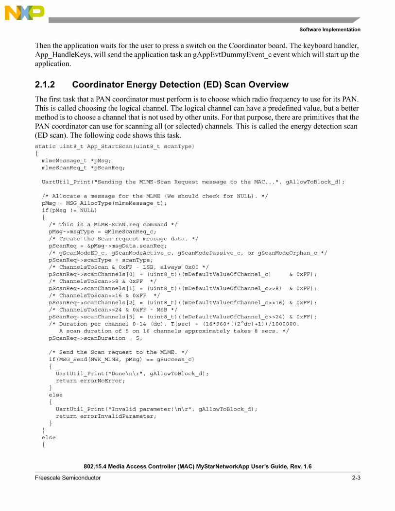
2.1.2 Coordinator Energy Detection (ED) Scan Overview
The first task that a PAN coordinator must perform is to choose which radio frequency to use for its PAN. This is called choosing the logical channel. The logical channel can have a predefined value, but a better method is to choose a channel that is not used by other units. For that purpose, there are primitives that the PAN coordinator can use for scanning all (or selected) channels. This is called the energy detection scan (ED scan). The following code shows this task.static uint8_t App_StartScan(uint8_t scanType){ mlmeMessage_t *pMsg; mlmeScanReq_t *pScanReq;
UartUtil_Print("Sending the MLME-Scan Request message to the MAC...", gAllowToBlock_d);
/* Allocate a message for the MLME (We should check for NULL). */ pMsg = MSG_AllocType(mlmeMessage_t); if(pMsg != NULL) { /* This is a MLME-SCAN.req command */ pMsg->msgType = gMlmeScanReq_c; /* Create the Scan request message data. */ pScanReq = &pMsg->msgData.scanReq; /* gScanModeED_c, gScanModeActive_c, gScanModePassive_c, or gScanModeOrphan_c */ pScanReq->scanType = scanType; /* ChannelsToScan & 0xFF - LSB, always 0x00 */ pScanReq->scanChannels[0] = (uint8_t)((mDefaultValueOfChannel_c) & 0xFF); /* ChannelsToScan>>8 & 0xFF */ pScanReq->scanChannels[1] = (uint8_t)((mDefaultValueOfChannel_c>>8) & 0xFF); /* ChannelsToScan>>16 & 0xFF */ pScanReq->scanChannels[2] = (uint8_t)((mDefaultValueOfChannel_c>>16) & 0xFF); /* ChannelsToScan>>24 & 0xFF - MSB */ pScanReq->scanChannels[3] = (uint8_t)((mDefaultValueOfChannel_c>>24) & 0xFF); /* Duration per channel 0-14 (dc). T[sec] = (16*960*((2^dc)+1))/1000000. A scan duration of 5 on 16 channels approximately takes 8 secs. */ pScanReq->scanDuration = 5; /* Send the Scan request to the MLME. */ if(MSG_Send(NWK_MLME, pMsg) == gSuccess_c) {
UartUtil_Print("Done\n\r", gAllowToBlock_d); return errorNoError; } else {
UartUtil_Print("Invalid parameter!\n\r", gAllowToBlock_d); return errorInvalidParameter; } } else {

Software Implementation
802.15.4 Media Access Controller (MAC) MyStarNetworkApp User’s Guide, Rev. 1.6
2-4 Freescale Semiconductor
/* Allocation of a message buffer failed. */UartUtil_Print("Message allocation failed!\n\r", gAllowToBlock_d);
return errorAllocFailed; }}
In this case, the scanType parameter for App_StartScan must be set to gScanModeED_c. Other types of scanning are explained later in this chapter. If there is any activity on a channel at the time the PAN coordinator scans that channel, this shows up in the result of the scan. A channel that showed no sign of activity at the time of the scan, shows an energy level of approximately 0x00. The higher the number, the more activity was detected on that channel.
The previous code example scans all 16 available channels in the 2.4 GHz band. The parameter scanChannels is a bit mask where each bit that is set indicates that this channel must be scanned. Because the 2.4 GHz band contains channel numbers 11 to 26, bits 11 to 26 are set in the scanChannels bit mask. Lower channel numbers are ignored. Also, the scanDuration parameter tells the MAC how long to scan each channel. The numbers 0 to 14 are valid entries for this parameter. The higher the number, the longer the time spent scanning. The exact scan duration for each channel can be calculated using this equation:
Scan duration = 15.36 ms · (2scanDuration + 1) Eqn. 2-1
The scanDuration parameter in the example requests scanning for approximately 0.5 seconds on each of the 16 channels. Once the scan request message has successfully been sent to the MLME, the scanning commences and a scan confirmation (a nwkMessage_t struct with msgType == gNwkScanCnf_c) is received asynchronously in the SAP handler for the messages from the MLME to the NWK. The following code processes the scan confirmation message.static void App_HandleScanEdConfirm(nwkMessage_t *pMsg){ uint8_t n, minEnergy; uint8_t *pEdList; uint8_t ChannelMask;
UartUtil_Print("Recevied the MLME-Scan Confirm message from the MAC\n\r", gAllowToBlock_d); /* Get a pointer to the energy detect results */ pEdList = pMsg->msgData.scanCnf.resList.pEnergyDetectList; /* Set the minimum energy to a large value */ minEnergy = 0xFF;
/* Select default channel */ mLogicalChannel = 11; /* Search for the channel with least energy */ for(n=0; n<16; n++) { ChannelMask = n + 11;
if((pEdList[n] < minEnergy)&&((uint8_t)((mDefaultValueOfChannel_c>>ChannelMask) & 0x1))) { minEnergy = pEdList[n]; /* Channel numbering is 11 to 26 both inclusive */
Software Implementation
802.15.4 Media Access Controller (MAC) MyStarNetworkApp User’s Guide, Rev. 1.6
Freescale Semiconductor 2-5
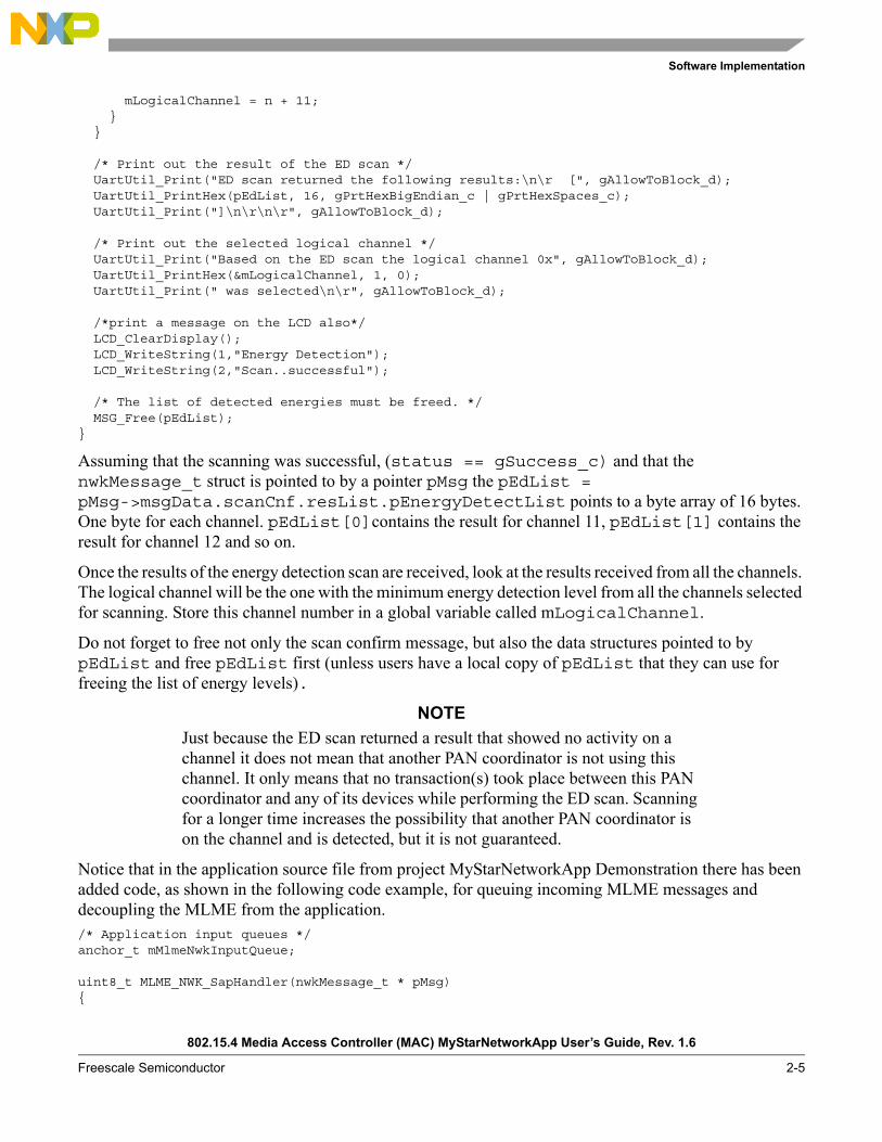
mLogicalChannel = n + 11; } } /* Print out the result of the ED scan */ UartUtil_Print("ED scan returned the following results:\n\r [", gAllowToBlock_d); UartUtil_PrintHex(pEdList, 16, gPrtHexBigEndian_c | gPrtHexSpaces_c); UartUtil_Print("]\n\r\n\r", gAllowToBlock_d); /* Print out the selected logical channel */ UartUtil_Print("Based on the ED scan the logical channel 0x", gAllowToBlock_d); UartUtil_PrintHex(&mLogicalChannel, 1, 0); UartUtil_Print(" was selected\n\r", gAllowToBlock_d); /*print a message on the LCD also*/ LCD_ClearDisplay(); LCD_WriteString(1,"Energy Detection"); LCD_WriteString(2,"Scan..successful"); /* The list of detected energies must be freed. */ MSG_Free(pEdList);}
Assuming that the scanning was successful, (status == gSuccess_c) and that the nwkMessage_t struct is pointed to by a pointer pMsg the pEdList = pMsg->msgData.scanCnf.resList.pEnergyDetectList points to a byte array of 16 bytes. One byte for each channel. pEdList[0]contains the result for channel 11, pEdList[1] contains the result for channel 12 and so on.
Once the results of the energy detection scan are received, look at the results received from all the channels. The logical channel will be the one with the minimum energy detection level from all the channels selected for scanning. Store this channel number in a global variable called mLogicalChannel.
Do not forget to free not only the scan confirm message, but also the data structures pointed to by pEdList and free pEdList first (unless users have a local copy of pEdList that they can use for freeing the list of energy levels).
NOTE
Just because the ED scan returned a result that showed no activity on a channel it does not mean that another PAN coordinator is not using this channel. It only means that no transaction(s) took place between this PAN coordinator and any of its devices while performing the ED scan. Scanning for a longer time increases the possibility that another PAN coordinator is on the channel and is detected, but it is not guaranteed.
Notice that in the application source file from project MyStarNetworkApp Demonstration there has been added code, as shown in the following code example, for queuing incoming MLME messages and decoupling the MLME from the application./* Application input queues */anchor_t mMlmeNwkInputQueue;
uint8_t MLME_NWK_SapHandler(nwkMessage_t * pMsg){
Software Implementation
802.15.4 Media Access Controller (MAC) MyStarNetworkApp User’s Guide, Rev. 1.6
2-6 Freescale Semiconductor
/* Put the incoming MLME message in the applications input queue. */ MSG_Queue(&mMlmeNwkInputQueue, pMsg);
TS_SendEvent(gAppTaskID_c, gAppEvtMessageFromMLME_c); return gSuccess_c;}
Also, in the application task there is added code for processing incoming messages from that queue as shown in this code example./* We have an event from MLME_NWK_SapHandler */if (events & gAppEvtMessageFromMLME_c){ pMsgIn = MSG_DeQueue(&mMlmeNwkInputQueue); … /* Process message if pMsgIn!=NULL */
/* Messages from the MLME must always be freed. */ MSG_Free(pMsgIn);}
By implementing the MLME to NWK SAP handler this way, the MLME and NWK/APP are completely decoupled. That is, the SAP handler only queues the message but does not do any processing of the message. In this way, the MLME returns from the call as fast as possible and the call stack of the MCU is exercised as little as possible reducing the risk of getting a call stack overflow.
2.1.3 Coordinator Short Address Assignment
Now the coordinator must assign itself a short address. All Freescale development boards come with a pre-assigned extended address, but a short address must be assigned before starting the PAN. Otherwise, the start request will fail. Because the PAN coordinator is the first unit to participate in its own PAN, it can choose any short address for itself. Once the short address is chosen, it is usually hard-coded, it must be set by setting the macShortAddress PIB attribute. This is done in App_StartCoordinator(), shown in the following example code./* We must always set the short address to something else than 0xFFFF before starting a PAN. */ pMsg->msgType = gMlmeSetReq_c; pMsg->msgData.setReq.pibAttribute = gMPibShortAddress_c; pMsg->msgData.setReq.pibAttributeValue = (uint8_t *)maShortAddress; ret = MSG_Send(NWK_MLME, pMsg);
In the above code example, the short address of the PAN coordinator is set to the value of maShortAddress. As the reset request, the MLME-SET.request is also completed synchronously. So, if ret == gSuccess_c after calling MSG_Send(), the PIB attribute was set successfully. The pibAttributeValue parameter is not freed by the MLME.
The short address must be different from 0xFFFF. A short address of 0xFFFE tells the coordinator to use its long address in all transactions. If the short address is set to anything different from 0xFFFF and 0xFFFE, the PAN coordinator uses this address instead of its extended address and thus sends shorter packets. An extended address is 8 bytes long and a short address is 2 bytes long.

Software Implementation
802.15.4 Media Access Controller (MAC) MyStarNetworkApp User’s Guide, Rev. 1.6
Freescale Semiconductor 2-7
2.1.4 Coordinator PAN ID Selection
After selecting the logical channel, the last thing required before starting a PAN, is for the coordinator to select an identification number which is called PAN ID. Assuming that there is no other PAN using the same logical channel, the new PAN coordinator can freely choose a PAN ID. However, users may want to perform an active scan of the channel to see if there really are no other PAN coordinators using the same logical channel. If so, the PAN ID used must be different from the ones used by other PAN coordinators on the same logical channel. In the application source file from Star Network Demonstration (Coordinator) project it is assumed that no other IEEE 802.15.4 PAN is present.
2.1.5 Coordinator PAN Startup
After choosing the logical channel, PAN ID and short address, it is time to start up the PAN using the MLME_START.request primitive.
The panCoordinator parameter indicates whether the start request is to start up a PAN coordinator or a coordinator. For an explanation of the difference, see the IEEE 802.15.4 Standard. In this example a PAN coordinator is started.
The beaconOrder and superFrameOrder parameters are set to 0x0F because a non-beacon network is started. See the 802.15.4 Standard about how to start a beacon network. Any combination of beaconOrder and superFrameOrder where beaconOrder is set to 0x0F creates a non-beacon network.
The batteryLifeExt parameter is ignored for now and is set to 0x00.
The coordRealignment parameter tells the MLME whether it should send out a coordinator realignment command prior to starting up the PAN. For now, users should set this to 0x00 (no coordinator realignment command) because it is not relevant for this example.
Finally, the securityEnable parameter tells the MLME if it should apply any security to the transactions taking place over the air. For now, users should leave this set to 0x00 (no security). App_StartCoordinator() in Star Network Demonstration (Coordinator) application contains the code for starting a PAN./* Message for the MLME will be allocated and attached to this pointer */ mlmeMessage_t *pMsg;
UartUtil_Print("Sending the MLME-Start Request message to the MAC...", gAllowToBlock_d); /* Allocate a message for the MLME (We should check for NULL). */ pMsg = MSG_AllocType(mlmeMessage_t); if(pMsg != NULL) { /* Pointer which is used for easy access inside the allocated message */ mlmeStartReq_t *pStartReq; /* Return value from MSG_send - used for avoiding compiler warnings */ uint8_t ret; /* Boolean value that will be written to the MAC PIB */ uint8_t boolFlag; /* Set-up MAC PIB attributes. Please note that Set, Get, and Reset messages are not freed by the MLME. */
Software Implementation
802.15.4 Media Access Controller (MAC) MyStarNetworkApp User’s Guide, Rev. 1.6
2-8 Freescale Semiconductor
/* We must always set the short address to something else than 0xFFFF before starting a PAN. */ pMsg->msgType = gMlmeSetReq_c; pMsg->msgData.setReq.pibAttribute = gMPibShortAddress_c; pMsg->msgData.setReq.pibAttributeValue = (uint8_t *)maShortAddress; ret = MSG_Send(NWK_MLME, pMsg); /* We must set the Association Permit flag to TRUE in order to allow devices to associate to us. */ pMsg->msgType = gMlmeSetReq_c; pMsg->msgData.setReq.pibAttribute = gMPibAssociationPermit_c; boolFlag = TRUE; pMsg->msgData.setReq.pibAttributeValue = &boolFlag; ret = MSG_Send(NWK_MLME, pMsg); /* This is a MLME-START.req command */ pMsg->msgType = gMlmeStartReq_c; /* Create the Start request message data. */ pStartReq = &pMsg->msgData.startReq; /* PAN ID - LSB, MSB. The example shows a PAN ID of 0xBEEF. */ FLib_MemCpy(pStartReq->panId, (void *)maPanId, 2); /* Logical Channel - the default of 11 will be overridden */ pStartReq->logicalChannel = mLogicalChannel; /* Beacon Order - 0xF = turn off beacons */ pStartReq->beaconOrder = 0x0F; /* Superframe Order - 0xF = turn off beacons */ pStartReq->superFrameOrder = 0x0F; /* Be a PAN coordinator */ pStartReq->panCoordinator = TRUE; /* Dont use battery life extension */ pStartReq->batteryLifeExt = FALSE; /* This is not a Realignment command */ pStartReq->coordRealignment = FALSE; /* Dont use security */ pStartReq->securityEnable = FALSE; /* Send the Start request to the MLME. */ if(MSG_Send(NWK_MLME, pMsg) == gSuccess_c) { UartUtil_Print("Done\n\r", gAllowToBlock_d); return errorNoError; } else { /* One or more parameters in the Start Request message were invalid. */ UartUtil_Print("Invalid parameter!\n\r", gAllowToBlock_d); return errorInvalidParameter; } } else { /* Allocation of a message buffer failed. */ UartUtil_Print("Message allocation failed!\n\r", gAllowToBlock_d); return errorAllocFailed; }
Software Implementation
802.15.4 Media Access Controller (MAC) MyStarNetworkApp User’s Guide, Rev. 1.6
Freescale Semiconductor 2-9
A start confirmation is received asynchronously on the SAP that handles the messages from the MLME to the NWK. The application task is notified by sending to it the gAppEvtMessageFromMLME_c event. If the PAN was started successfully, a status code of gSuccess_c is returned. The MLME-START.confirm message is processed i in the state stateStartCoordinatorWaitConfirm, as shown in the following code.case stateStartCoordinatorWaitConfirm: /* Stay in this state until the Start confirm message arrives, and then goto the Listen state. */ if (events & gAppEvtMessageFromMLME_c) { if (pMsgIn) { ret = App_WaitMsg(pMsgIn, gNwkStartCnf_c); if(ret == errorNoError) { UartUtil_Print("Started the coordinator with PAN ID 0x", gAllowToBlock_d); UartUtil_PrintHex((uint8_t *)maPanId, 2, 0); UartUtil_Print(", and short address 0x", gAllowToBlock_d); UartUtil_PrintHex((uint8_t *)maShortAddress, 2, 0); UartUtil_Print(".\n\r", gAllowToBlock_d); /*print a message on the LCD also*/ LCD_ClearDisplay(); LCD_WriteString(1,"PAN coordinator"); LCD_WriteString(2,"started"); } } } break;
After successfully starting a PAN, the macRxOnWhenIdle PIB is set to 0x01. This means that whenever the PAN coordinator is not transmitting a packet, it is listening for incoming packets. This is implemented this way because it is not logical to start a PAN and then not start listening for incoming association requests or beacon requests from devices performing active scans. However, if this behavior is unwanted, the macRxOnWhenIdle PIB can be set back to its default value of 0x00.
All that needs to be done on the PAN coordinator is to set the PIB attribute macAssociationPermit to 0x01 in order to ensure that devices are allowed to associate to the PAN coordinator. If this PIB is left untouched, or at any time set to 0x00, any incoming association requests from a device will be ignored by the MAC (see App_StartCoordinator()) as shown in the following code./* We must set the Association Permit flag to TRUE in order to allow devices to associate to us. */pMsg->msgType = gMlmeSetReq_c;pMsg->msgData.setReq.pibAttribute = gMacPibAssociationPermit_c;boolFlag = TRUE;pMsg->msgData.setReq.pibAttributeValue = &boolFlag;ret = MSG_Send(NWK_MLME, pMsg);
As was the case when setting the macShortAddress PIB, the ret variable contains gSuccess_c if the PIB was successfully set.
In the above source code example, the allocated message pMsg was used repeatedly for setting PIB attributes and for starting the PAN. When setting PIB attributes the message is not freed by the MLME so it can be reused. But as soon as pMsg is used for requesting the startup of a PAN, the message is no longer
Software Implementation
802.15.4 Media Access Controller (MAC) MyStarNetworkApp User’s Guide, Rev. 1.6
2-10 Freescale Semiconductor
valid in the application context. Now the message is owned and freed by the MLME. So, in App_StartCoordinator(), pMsg is never freed because this is done by the MLME.
2.1.6 Coordinator End Device Acceptance
When an End Device issues an associate request indicating that it wants to associate to the PAN, the Coordinator calls the App_SendAssociateResponse function that checks if the PAN has reached its capacity by searching if there are any available addresses as shown in the following code:if(0x0F > mAddressesMap){ /* We can assign 1, 2, 4 and 8 as a short address. Check the map and determine the first free address. */ while((selectedAddress & mAddressesMap) != 0) { selectedAddress = selectedAddress << 1; }
pAssocRes->assocShortAddress[0] = selectedAddress; pAssocRes->assocShortAddress[1] = 0x00;
/* Association granted.*/ requestResolution = gSuccess_c; } else { /* Signal that we do not have a valid short address. */ pAssocRes->assocShortAddress[0] = 0xFE; pAssocRes->assocShortAddress[1] = 0xFF; requestResolution = gPanAtCapacity_c;}
An End Device can be assigned one of the addresses 1, 2, 4 and 8. The lowest 4 bits of the variable addressesMap indicate which of these 4 addresses are available (the corresponding bit is 0). The first available address is assigned to the device and if the MSG_Send() function returns gSuccess_c, the address is OR-ed with the addressesMap. The addressesMap is initially 0x00 meaning that all the addresses are available.
The first End Device that tries to associate gets Address 1 and then the mAddressesMap is set to 0x01. The second End Device that tries to associate gets Address 2 and then the mAddressesMap is set to 0x02. Then an ASSOCIATION.response message is sent to indicate that the End Device has been accepted along with the short address that was assigned.
When the mAddressesMap variable is 0x0F, the PAN is full and the status of the ASSOCIATION.response is set on gPanAtCapacity_c. In this case, the address field of the ASSOCIATION.response must be set on a valid address value, otherwise the MSG_Send() function returns an “Invalid Parameter” error.
2.1.7 Sending Data to the End Devices
The App_TransmitData function is called every time the Coordinator is in the listen state for sending data to the devices associated to the PAN. It first checks whether the sending conditions are fulfilled as shown in the following code:
Software Implementation
802.15.4 Media Access Controller (MAC) MyStarNetworkApp User’s Guide, Rev. 1.6
Freescale Semiconductor 2-11
/* We transmit only if at least one device is associated. */if(mAddressesMap == 0){ return;
}
/* Send packets only if we can send info to all End Devices */if(mcPendingPackets > 0){
if(mPacketDropped > 0) {
UartUtil_Print("Packet dropped.\n\r", gAllowToBlock_d);mPacketDropped = 0;
}return;
}
The data sent to the End Devices associated to the network can arrive from two different sources:
• The counter value that is updated on the timer interrupt
• The UART interface
The mCounterLEDsModified variable counter indicates if the current value of the counter is already sent. If there is data to be transmitted (either from the timer or from the UART), the Coordinator creates a message for every device connected to the PAN which stores the data, along with information about the destination and the source device as shown in the following code:/* Create an MCPS-Data Request message containing the data. */mpPacket->msgType = gMcpsDataReq_c;/* Copy data to be sent to packet */mpPacket->msgData.dataReq.pMsdu = (uint8_t*)(&(mpPacket->msgData.dataReq.pMsdu)) + sizeof(uint8_t*);memcpy(mpPacket->msgData.dataReq.pMsdu, (void *)pData, length);/* Create the header using device information stored when creating the association response. In this simple example the use of shortaddresses is hardcoded. In a real world application we must beflexible, and use the address mode required by the given situation. */mpPacket->msgData.dataReq.dstAddr[0] = deviceAddress; mpPacket->msgData.dataReq.dstAddr[1] = 0; memcpy(mpPacket->msgData.dataReq.srcAddr, (void *)maShortAddress, 2);memcpy(mpPacket->msgData.dataReq.dstPanId, (void *)maPanId, 2);memcpy(mpPacket->msgData.dataReq.srcPanId, (void *)maPanId, 2);mpPacket->msgData.dataReq.dstAddrMode = gAddrModeShort_c;mpPacket->msgData.dataReq.srcAddrMode = gAddrModeShort_c;mpPacket->msgData.dataReq.msduLength = length;/* Request MAC level acknowledgement, and indirect transmission of the data packet */mpPacket->msgData.dataReq.txOptions = gTxOptsAck_c | gTxOptsIndirect_c;/* Give the data packet a handle. The handle isreturned in the MCPS-Data Confirm message. */mpPacket->msgData.dataReq.msduHandle = mMsduHandle++;/* Add the packet to tracking list in the purger module. */ret = Purger_Track(mpPacket->msgData.dataReq.msduHandle, 0, deviceAddress, mCounterLEDs); /* Send the Data Request to the MCPS */NR MSG_Send(NWK_MCPS, mpPacket);/* Prepare for another data buffer */mpPacket = NULL;

Software Implementation
802.15.4 Media Access Controller (MAC) MyStarNetworkApp User’s Guide, Rev. 1.6
2-12 Freescale Semiconductor
mcPendingPackets++;
The transmission method is specified in the txOptions field (indirect transmission with acknowledgement). The message is sent to the MCPS and its handle and recipient address are stored in the Purger tracking list. The mcPendingPackets stores the number of packets currently waiting to be taken by the recipient.
When the End Device has received the packet it sends a MCPS-DATA.confirm message that directs the Coordinator to remove the packet from the Purger's list and decrement the mcPendingPackets variable as shown in the following code:static void App_HandleMcpsInput(mcpsToNwkMessage_t *pMsgIn){ uint8_t ret = 0; switch(pMsgIn->msgType) { /* The MCPS-Data confirm is sent by the MAC to the network or application layer when data has been sent. */ case gMcpsDataCnf_c: if(mcPendingPackets) { mcPendingPackets--; } /* Remove the packet from the purger tracklist.*/ ret = Purger_Remove(pMsgIn->msgData.dataCnf.msduHandle); break;
case gMcpsDataInd_c: /* The MCPS-Data indication is sent by the MAC to the network or application layer when data has been received. We simply format the message and copy it to the UART. */ UartUtil_Print("\n\rDevice address: ", gAllowToBlock_d); UartUtil_PrintHex((uint8_t*)&pMsgIn->msgData.dataInd.srcAddr[1], 1, 0); UartUtil_PrintHex((uint8_t*)&pMsgIn->msgData.dataInd.srcAddr[0], 1, 0); UartUtil_Print(":", gAllowToBlock_d); UartUtil_PrintHex((uint8_t*)&pMsgIn->msgData.dataInd.mpduLinkQuality, 1, 0); UartUtil_Print(":", gAllowToBlock_d); UartUtil_Tx(pMsgIn->msgData.dataInd.pMsdu, pMsgIn->msgData.dataInd.msduLength); break;
case gMcpsPurgeCnf_c: /* We have confirmation that the packet was removed from the indirect queue, so decrement the number of pending packets. */ if(mcPendingPackets) mcPendingPackets--; break; } }
2.2 Understanding The Purger
The Purger is implemented as a separate module (Purger.c) and is used for tracking the data packets that are sent to the MCPS. The Purger allows the Coordinator to detect when End Devices disconnect from the PAN without invoking the DISASSOCIATE.request primitive.
Software Implementation
802.15.4 Media Access Controller (MAC) MyStarNetworkApp User’s Guide, Rev. 1.6
Freescale Semiconductor 2-13
2.2.1 Purger Initialization
The Purger_Init function is called in the MApp_Init function before the first packet is sent. It initializes the array of packets, the packets life time and specifies the function that implements application specific reaction to a purged packet. Its implementation is shown in the following code:
gPurgerExpireInterval = expireInterval; ptAppProcessAddress = appFn;
for(i = 0; i < mPurgerNumPackets_c; i++) { msgTrackArray[i].slotStatus = mPurgerUnusedSlot_c; }
2.2.2 Purger Tracking Function
The Purger_Track function will add the packet handler to the list of tracked packets, along with the destination device's address and the expiration time.
uint8_t result = purgerNoSlot;
for(i = 0; i < mPurgerNumPackets_c; i++) { if(mPurgerUnusedSlot_c == msgTrackArray[i].slotStatus) { msgTrackArray[i].msduHandle = msdu; msgTrackArray[i].destAddressHigh = destHigh; msgTrackArray[i].destAddressLow = destLow; msgTrackArray[i].expirationTime = time + gPurgerExpireInterval; msgTrackArray[i].slotStatus = mPurgerUsedSlot_c; result = purgerNoError; break; } }
This function searches for an unused slot in the array of tracked packets and adds the new packet. It returns PurgerNoSlot error code if the array is full or PurgerNoError otherwise.
2.2.3 Purger Check Function
While in the listen state, the Coordinator periodically calls the Purger_Check function which sends purge requests to the MAC for the expired packets and calls the application specific function handler. For example, the App_RemoveDevice defined in MyStarNetworkApp updates the mAddressesMap variable so it indicates that the address of the device that has left the PAN is available for another device as shown in the following code:static void App_RemoveDevice(uint8_t shortAddrHigh, uint8_t shortAddrLow){ /* Variable shortAddrHigh not used in this release*/ uint8_t addHigh = shortAddrHigh;
/* Remove the end device from the associated devices map - perhaps this should be a call to an app provided fn.*/ mAddressesMap &= ~(shortAddrLow); App_UpdateLEDs();
Software Implementation
802.15.4 Media Access Controller (MAC) MyStarNetworkApp User’s Guide, Rev. 1.6
2-14 Freescale Semiconductor
UartUtil_Print("\n\rDisconnected device: ", gAllowToBlock_d); UartUtil_PrintHex(&shortAddrLow, 1, 0); UartUtil_Print(".\n\r", gAllowToBlock_d); }
The Purger_check function iterates through the array of tracked packets. Each of the packets found in the array is checked. If it has expired, that is, the current time is greater than or equal to the packet's expiration time, a Purge.request is sent to the MCPS specifying the handle of the packet to be purged. Then the application specific handler function pointed to by the ptAppProcessAddress is called. The number of purged packets is returned as shown in the following code:for(i = 0; i < mPurgerNumPackets_c; i++) { if((msgTrackArray[i].slotStatus == mPurgerUsedSlot_c) && (time >= msgTrackArray[i].expirationTime) && ((uint8_t)(msgTrackArray[i].expirationTime - time) > gPurgerExpireInterval)) { purgeRequestPacket = MSG_Alloc(sizeof(primNwkToMcps_t) + sizeof(mcpsPurgeReq_t)); if(purgeRequestPacket != NULL) { /* Create an MCPS-Purge Request message containing the msdu. */ purgeRequestPacket->msgType = gMcpsPurgeReq_c; /* Specify the message to purge. */ purgeRequestPacket->msgData.purgeReq.msduHandle = msgTrackArray[i].msduHandle; /* Send the Data Request to the MCPS */ NR MSG_Send(NWK_MCPS, purgeRequestPacket);
#if mPurgerVerboseMode_c == 1 UartUtil_Print("Sent purge request for ", gAllowToBlock_d); UartUtil_PrintHex(&purgeRequestPacket->msgData.purgeReq.msduHandle, 1, gPrtHexNewLine_c);#endif //mPurgerVerboseMode_c
ptAppProcessAddress(msgTrackArray[i].destAddressHigh, msgTrackArray[i].destAddressLow); /* Remove it from the tracking list. */ ret = Purger_Remove(msgTrackArray[i].msduHandle); result++; } else { /* If this happens, this function will get called until the memory manager has memory to allocate the packet. */ UartUtil_Print("Can't allocate purge request packet.\n\r", gAllowToBlock_d); } }}
2.2.4 Purger Remove Function
The packet is removed from the msgTrackArray list just after the purge message was sent. Another approach is to call the Purger_Remove() function when the MCPS-PURGE.confirm message was received. Given the fact that the purge request is treated locally in the MAC, it is not necessary to wait for the confirmation.
Software Implementation
802.15.4 Media Access Controller (MAC) MyStarNetworkApp User’s Guide, Rev. 1.6
Freescale Semiconductor 2-15
NOTE
There is a low probability that a packet that has its expirationTime field equal to 255 and the Purger_check function is not called when the time is 255, but called when time = 0. In this event, the packet is not purged according to the algorithm just described. It is dropped when the Purger_check function is called at time = 255.
The Purger_Remove function is called when the Coordinator receives a MCPS-DATA.confirmation. That is, when the packet has been received by the destination device.uint8_t Purger_Remove(uint8_t msdu){ uint8_t i; uint8_t result = purgerNoMessage;
for(i = 0; i < mPurgerNumPackets_c; i++) { if(msgTrackArray[i].msduHandle == msdu) { msgTrackArray[i].slotStatus = mPurgerUnusedSlot_c;
#if mPurgerVerboseMode_c == 1 UartUtil_Print("Untracked: ", gAllowToBlock_d); UartUtil_PrintHex(&msgTrackArray[i].msduHandle, 1, gPrtHexNewLine_c);#endif //mPurgerVerboseMode_c
result = purgerNoError; break; } }
return result;}
This function removes the specified packet identifier from the list of tracked packets. As shown in this code snippet, this is accomplished by marking the corresponding spot as unused. The PurgerNoMessage value is returned if there is no packet with the specified identifier, otherwise PurgerNoError is returned.
NOTE
The handler of a tracked packet is represented on one byte, so there can be at most 255 uniquely identified packets in the tracking list at a time. This can be achieved by choosing a mMaxPendingDataPackets_c value less than 255 and an appropriate expiration interval for the Purger. This ensures that the packets do not stay too long in the tracking list.
2.3 Understanding End Devices
On the End Device side, the application is implemented in the MApp.c file from the Star Network Demonstration (End Device) project.
Before associating to a PAN Coordinator, the End Device first needs to find a PAN Coordinator that is accepting incoming association requests. For that purpose, the End Device must use the active scan feature. This feature is initiated much the same way as the ED scan and users can reuse the
Software Implementation
802.15.4 Media Access Controller (MAC) MyStarNetworkApp User’s Guide, Rev. 1.6
2-16 Freescale Semiconductor
App_StartScan() function as described in Section 2.3.1, “Finding the PAN”. The only difference is that the scanType parameter must now be set to gScanModeActive_c. The device could also do an ED scan prior to doing the active scan in order to estimate which logical channels would be worth doing active scan on. However, because the PAN that was set up by the PAN Coordinator is non-beacon and thus there is no air-traffic available to detect in the ED scan. Because there is no other data on the air, users should not perform an ED scan on the End Device.
2.3.1 Finding the PAN
After receiving the active scan request, the MLME starts sending out beacon requests on the requested channels (in the scanChannels parameter) and starts listening for beacons from (PAN) coordinators for as long as indicated in the scanDuration parameter. Basically, sending a beacon request is like asking, “Are there any PAN coordinators out there that have a PAN on this channel?” and a PAN coordinator sending back a beacon means, “Yes, I have a PAN, here is my PAN information”.
Because the device does not know which channel the PAN coordinator chose after performing the ED scan, the device will be scanning all channels. Assuming that only the PAN coordinator that was just started is in the vicinity of the device and it did see the beacon request, a scan confirm with the status == gSuccess_c and resultListSize == 1 is returned. If no answer was received, then status == gNoBeacon_c.
After receiving the scan confirmation, now look at the pDescBlock pointer in the scan confirmation message and to the data it contains. The descriptorList is an array of structures of type panDescriptor_t as many as are indicated in the descriptorCount parameter as shown in the following code example.struct panDescriptorBlock_tag { panDescriptor_t descriptorList[aScanResultsPerBlock]; uint8_t descriptorCount; struct panDescriptorBlock_tag *pNext; };
typedef struct panDescriptor_tag { uint8_t coordAddress[8]; uint8_t coordPanId[2]; uint8_t coordAddrMode; uint8_t logicalChannel; bool_t securityUse; uint8_t aclEntry; bool_t securityFailure; uint8_t superFrameSpec[2]; bool_t gtsPermit; uint8_t linkQuality; uint8_t timeStamp[3];} panDescriptor_t;
The scan confirm can contain up to two (2) PAN descriptor blocks.
Using the list of panDescriptor_t structure, the device can decide which coordinator to associate to. The Star Network Demonstration (End Device) is a non beacon without security demonstration application, therefore does not use the following parameters: securityUse, aclEntry, securityFailure, gtsPermit and timeStamp.
Software Implementation
802.15.4 Media Access Controller (MAC) MyStarNetworkApp User’s Guide, Rev. 1.6
Freescale Semiconductor 2-17
The coordAddrMode determines whether the Coordinator is using its extended address or is using a short address. If set to gAddrModeShort_c the PAN Coordinator uses a 16 bit short address and only the first two bytes in coordAddress are valid and contains (in little endian mode) the short address of the PAN Coordinator. If coordAddrMode is set to gAddrModeLong_c all 8 bytes of the coordAddress parameter are valid and contains (in little endian mode) the full address of the PAN Coordinator.
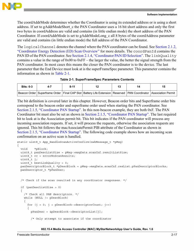
The logicalChannel denotes the channel where the PAN coordinator can be found. See Section 2.1.2, “Coordinator Energy Detection (ED) Scan Overview” for more details. The coordPanId contains the PAN ID of the PAN coordinator. See Section 2.1.4, “Coordinator PAN ID Selection”. The linkQuality contains a value in the range of 0x00 to 0xFF – the larger the value, the better the signal strength from the PAN coordinator. In most cases this means the closer the PAN coordinator is to the device. The last parameter that the End Device must look at is the superFrameSpec parameter. This parameter contains the information as shown in Table 2-1.
The bit definition is covered later in this chapter. However, Beacon order bits and Superframe order bits correspond to the beacon order and superframe order used when starting the PAN coordinator. See Section 2.1.5, “Coordinator PAN Startup”. In this non-beacon example, they are both 0xF. The PAN Coordinator bit must also be set as shown in Section 2.1.5, “Coordinator PAN Startup”. The last required bit to look at is the Association permit bit. This bit indicates if the PAN coordinator will process any incoming association requests. If set, it will process the requests, otherwise the association requests are ignored. This bit follows the macAssociatePermit PIB attribute of the Coordinator as shown in Section 2.1.5, “Coordinator PAN Startup”. The following code example shows how an incoming scan confirmation on an active scan is handled.static uint8_t App_HandleScanActiveConfirm(nwkMessage_t *pMsg){ void *pBlock; uint8_t panDescListSize = pMsg->msgData.scanCnf.resultListSize; uint8_t rc = errorNoScanResults; uint8_t j; uint8_t bestLinkQuality = 0; panDescriptorBlock_t *pDescBlock = pMsg->msgData.scanCnf.resList.pPanDescriptorBlocks; panDescriptor_t *pPanDesc; /* Check if the scan resulted in any coordinator responses. */ if (panDescListSize > 0) { /* Check all PAN descriptors. */ while (NULL != pDescBlock) { for (j = 0; j < pDescBlock->descriptorCount; j++) { pPanDesc = &pDescBlock->descriptorList[j];
/* Only attempt to associate if the coordinator
Table 2-1. SuperFrameSpec Parameters Contents
Bits: 0-3 4-7 8-11 12 13 14 15
Beacon Order Superframe Order Final CAP Slot Battery Life Extension Reserved PAN Coordinator Association Permit

Software Implementation
802.15.4 Media Access Controller (MAC) MyStarNetworkApp User’s Guide, Rev. 1.6
2-18 Freescale Semiconductor
accepts associations and is non-beacon. */ if( ( pPanDesc->superFrameSpec[1] & gSuperFrameSpecMsbAssocPermit_c) && ((pPanDesc->superFrameSpec[0] & gSuperFrameSpecLsbBO_c) == 0x0F) ) { /* Find the nearest coordinator using the link quality measure. */ if(pPanDesc->linkQuality > bestLinkQuality) { /* Save the information of the coordinator candidate. If we find a better candiate, the information will be replaced. */ FLib_MemCpy(&mCoordInfo, pPanDesc, sizeof(panDescriptor_t)); bestLinkQuality = pPanDesc->linkQuality; rc = errorNoError; } } } /* Free current block */ pBlock = pDescBlock; pDescBlock = pDescBlock->pNext; MSG_Free(pBlock); } } if (pDescBlock) MSG_Free(pDescBlock); return rc;}
As this code example shows, the device stores the PAN descriptor for the chosen coordinator in a global variable called coordInfo. The contents of this PAN descriptor will be used in the next section when the device requests to be associated with the coordinator.Remember to free not only the scan confirm message (this is done in main() in the example application) but also the data structures pointed to by pMsg->msgData.scanCnf.resList.pPanDescriptorBlocks.
2.3.2 Associating to the PAN
From the PAN descriptor that was returned by the PAN coordinator, users can see if the coordinator accepts the incoming association requests, its short address and PAN ID. Next, users can associate the device to the PAN coordinator. Use the association request message (see MApp.c from Star Network Demonstration (End Device)) to accomplish this as shown in the following code example.static uint8_t App_SendAssociateRequest(void){ mlmeMessage_t *pMsg; mlmeAssociateReq_t *pAssocReq;
UartUtil_Print("Sending the MLME-Associate Request message to the MAC...", gAllowToBlock_d); /* Allocate a message for the MLME message. */ pMsg = MSG_AllocType(mlmeMessage_t); if(pMsg != NULL) { /* This is a MLME-ASSOCIATE.req command. */

Software Implementation
802.15.4 Media Access Controller (MAC) MyStarNetworkApp User’s Guide, Rev. 1.6
Freescale Semiconductor 2-19
pMsg->msgType = gMlmeAssociateReq_c; /* Create the Associate request message data. */ pAssocReq = &pMsg->msgData.associateReq; /* Use the coordinator info we got from the Active Scan. */ FLib_MemCpy(pAssocReq->coordAddress, mCoordInfo.coordAddress, 8); FLib_MemCpy(pAssocReq->coordPanId, mCoordInfo.coordPanId, 2); pAssocReq->coordAddrMode = mCoordInfo.coordAddrMode; pAssocReq->logicalChannel = mCoordInfo.logicalChannel; pAssocReq->securityEnable = FALSE; /* We want the coordinator to assign a short address to us. */ pAssocReq->capabilityInfo = gCapInfoAllocAddr_c; /* Send the Associate Request to the MLME. */ if(MSG_Send(NWK_MLME, pMsg) == gSuccess_c) { UartUtil_Print("Done\n\r", gAllowToBlock_d); return errorNoError; } else { /* One or more parameters in the message were invalid. */ UartUtil_Print("Invalid parameter!\n\r", gAllowToBlock_d); return errorInvalidParameter; } } else { /* Allocation of a message buffer failed. */ UartUtil_Print("Message allocation failed!\n\r", gAllowToBlock_d); return errorAllocFailed; }}
Most of the parameters in the association request message were described in previous sections. One new parameter is the capabilityInfo parameter. This bit mask is described in Table 2-2.
Table 2-2. CapabilityInfo Parameter Contents
Bit 0 Bit 1 Bit 2 Bit 3 Bits 4-5 Bit 6 Bit 7
Alternate PAN Coordinator
Device Type Power Source Receiver On When Idle
Reserved Security Capability Allocate Address
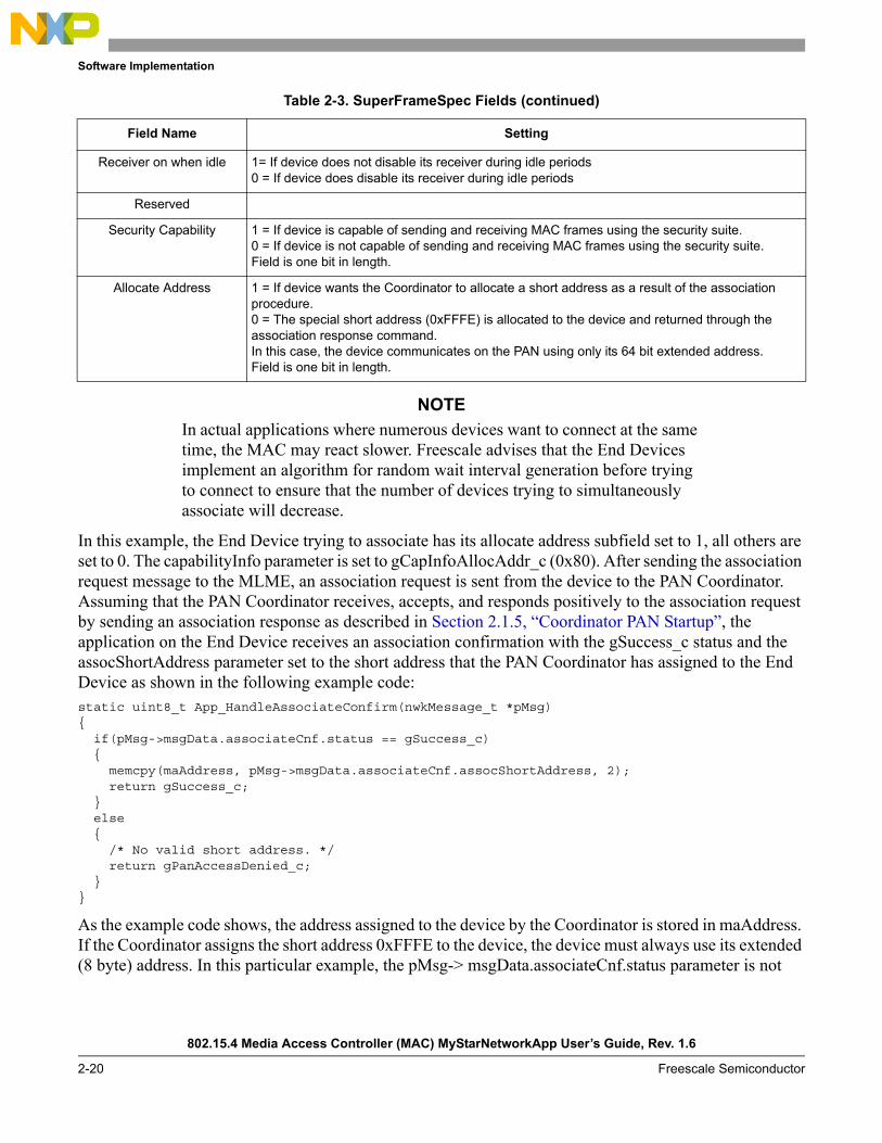
Table 2-3. SuperFrameSpec Fields
Field Name Setting
Alternate PAN Coordinator 1 = if device is capable of being a PAN Coordinator0 = If device is not capable of being a PAN Coordinator
Device Type 1 = If device is a Full Function Device (FFD)0 = If device is a Reduced Function Device (RFD)
Power Source 1 = If device is receiving power from AC power 0 = If device is not receiving power from AC power
Software Implementation
802.15.4 Media Access Controller (MAC) MyStarNetworkApp User’s Guide, Rev. 1.6
2-20 Freescale Semiconductor
NOTE
In actual applications where numerous devices want to connect at the same time, the MAC may react slower. Freescale advises that the End Devices implement an algorithm for random wait interval generation before trying to connect to ensure that the number of devices trying to simultaneously associate will decrease.
In this example, the End Device trying to associate has its allocate address subfield set to 1, all others are set to 0. The capabilityInfo parameter is set to gCapInfoAllocAddr_c (0x80). After sending the association request message to the MLME, an association request is sent from the device to the PAN Coordinator. Assuming that the PAN Coordinator receives, accepts, and responds positively to the association request by sending an association response as described in Section 2.1.5, “Coordinator PAN Startup”, the application on the End Device receives an association confirmation with the gSuccess_c status and the assocShortAddress parameter set to the short address that the PAN Coordinator has assigned to the End Device as shown in the following example code:static uint8_t App_HandleAssociateConfirm(nwkMessage_t *pMsg){ if(pMsg->msgData.associateCnf.status == gSuccess_c) { memcpy(maAddress, pMsg->msgData.associateCnf.assocShortAddress, 2); return gSuccess_c; } else { /* No valid short address. */ return gPanAccessDenied_c; } }
As the example code shows, the address assigned to the device by the Coordinator is stored in maAddress. If the Coordinator assigns the short address 0xFFFE to the device, the device must always use its extended (8 byte) address. In this particular example, the pMsg-> msgData.associateCnf.status parameter is not
Receiver on when idle 1= If device does not disable its receiver during idle periods0 = If device does disable its receiver during idle periods
Reserved
Security Capability 1 = If device is capable of sending and receiving MAC frames using the security suite. 0 = If device is not capable of sending and receiving MAC frames using the security suite. Field is one bit in length.
Allocate Address 1 = If device wants the Coordinator to allocate a short address as a result of the association procedure.0 = The special short address (0xFFFE) is allocated to the device and returned through the association response command.In this case, the device communicates on the PAN using only its 64 bit extended address. Field is one bit in length.
Table 2-3. SuperFrameSpec Fields (continued)
Field Name Setting

Software Implementation
802.15.4 Media Access Controller (MAC) MyStarNetworkApp User’s Guide, Rev. 1.6
Freescale Semiconductor 2-21
checked because the Coordinator always accepts incoming association requests. However, in a more extensive application, it would be necessary to check on this parameter.
2.3.3 Receiving Data From the Coordinator
In a non-beacon network the End Device must periodically send an MLME-POLL.request to the Coordinator to check if there is any data to be sent from the Coordinator. There can be issues if a second poll request is sent before the first poll request is confirmed by the Coordinator.static void App_ReceiveData(void){ /* Check if we are permitted, and if it is time to send a poll request. The poll interval is adjusted dynamically to the current band-width requirements. */ if(mWaitPollConfirm == FALSE) { /* This is an MLME-POLL.req command. */ mlmeMessage_t *pMlmeMsg = MSG_AllocType(mlmeMessage_t); if(pMlmeMsg) { /* Create the Poll Request message data. */ pMlmeMsg->msgType = gMlmePollReq_c;
/* Use the coordinator information we got from the Active Scan. */ memcpy(pMlmeMsg->msgData.pollReq.coordAddress, mCoordInfo.coordAddress, 8); memcpy(pMlmeMsg->msgData.pollReq.coordPanId, mCoordInfo.coordPanId, 2); pMlmeMsg->msgData.pollReq.coordAddrMode = mCoordInfo.coordAddrMode; pMlmeMsg->msgData.pollReq.securityEnable = FALSE;
/* Send the Poll Request to the MLME. */ if(MSG_Send(NWK_MLME, pMlmeMsg) == gSuccess_c) { /* Do not allow another Poll request before the confirm is received. */ mWaitPollConfirm = TRUE; } } }}
The App_ReceiveData function sends a poll request only if it is not already waiting for a poll confirmation (mWaitPollConfirm = FALSE) and if the MCU is not in Stop mode. The poll request message contains the PAN ID and the address of the Coordinator where the request is sent.
The Coordinator sends back a MLME-POLL.response which results in a MLME-POLL.confirm on the device as shown in the following code:static uint8_t App_HandleMlmeInput(nwkMessage_t *pMsg){ if(pMsg == NULL) { return errorNoMessage; }
/* Handle the incoming message. The type determines the sort of processing.*/ switch(pMsg->msgType)
Software Implementation
802.15.4 Media Access Controller (MAC) MyStarNetworkApp User’s Guide, Rev. 1.6
2-22 Freescale Semiconductor
{ case gNwkPollCnf_c: if(pMsg->msgData.pollCnf.status != gSuccess_c) { /* If we get to this point, then no data was available, and we allow a new poll request. Otherwise, we wait for the data indication before allowing the next poll request. */
mWaitPollConfirm = FALSE; } break; } return errorNoError;}
As this code example shows, a status value different from gSuccess_g indicates that there is no data available for the device on the Coordinator. If the Coordinator has data to transmit, it sends a MCPS-DATA.indication to the End Device containing that data, which, depending on its format, can be interpreted as the value of the Coordinator's timer or a text message to be output to the UART. This is implemented in the App_HandleMessage function, which is shown in the following code:static void App_HandleMessage(mcpsToNwkMessage_t *pMsgIn){ uint8_t val = *(pMsgIn->msgData.dataInd.pMsdu); if (( pMsgIn->msgData.dataInd.msduLength == 1 ) && ( val <= mDefaultValueOfMaxDisplayVal_c )) { App_UpdateLEDs(val); } else { uint8_t hex = pMsgIn->msgData.dataInd.mpduLinkQuality; UartUtil_Print("\n\rPAN Coordinator(0x", gAllowToBlock_d); UartUtil_PrintHex(&hex,1,0); UartUtil_Print("):", gAllowToBlock_d); UartUtil_Tx(pMsgIn->msgData.dataInd.pMsdu, pMsgIn->msgData.dataInd.msduLength); UartUtil_Print("\n\r", gAllowToBlock_d); }}
NOTE
Data packets may be lost if the Coordinator sends characters at a very high rate. This can be solved by reducing the poll request interval. This solution also implies that the low power interval must be reduced (See Section 2.3.5, “End Device Low Power Mode Overview”).
2.3.4 Sending Data to Coordinator
When users press a switch on the End Device a pre-defined text message is sent to the Coordinator. Every time a switch is pressed (after device associating process is finished), the App_HandleKeys is called and implicitly calling the App_SendPredefinedMessage function. Then it issues an MCPS-DATA.request to send the text message.

Software Implementation
802.15.4 Media Access Controller (MAC) MyStarNetworkApp User’s Guide, Rev. 1.6
Freescale Semiconductor 2-23
2.3.5 End Device Low Power Mode Overview
Low power consumption is one of the primary features of the 802.15.4 Standard. 802.15.4 Standard compliant, battery powered End Devices can run for months or even years.
To implement the low power capability of the 802.15.4 stack, the Star Network Demonstration (End Device) uses the Power Management Library (PWRLIB) because it is fully configurable, simple to use and provides efficiency in conserving power.
The PWRLIB needs to be initialized before it can be used. This is performed in the init state of the End Device by calling the following function:/* Initialize the Low Power Management module */ PWRLib_Init();
This function performs initialization of the PWRLIB and PWR functions. The End Device enters into Low Power Mode when no network activity is detected. Entering Low Power Mode is performed in the Idle task by calling the PWR_EnterLowPower() function as follows:
if(PWR_CheckIfDeviceCanGoToSleep()){
PWR_EnterLowPower();}
Inside the PWR_EnterLowPower function, PWR_CheckForAndEnterNewPowerState ( PWR_DeepSleep, cPWR_RTITicks) is called.
The PWR_DeepSleep parameter specifies that the transceiver is powered down and the MCU enters the Stop Mode.
The second parameter specifies the time interval in which the End Devices stay in Low Power Mode. The cPWR_RTITicks constant specifies the number of ticks from the Real Timer Interrupt. The total sleep interval is calculated by multiplying cPWR_RTITicks with cPWR_RTITickTime which specifies the time interval between two consecutive ticks. These constants can be modified in the PWR_Configuration.h file to adjust the sleep interval.
The PWR_CheckForAndEnterNewPowerState function blocks the application until the power down time interval elapses or some event causes the MCU and the transceiver to resume. The return value specifies the cause for waking up the End Device. As shown in the previous code example, the End Device tests to see if a key was pressed and sets the appropriate flag.

Software Implementation
802.15.4 Media Access Controller (MAC) MyStarNetworkApp User’s Guide, Rev. 1.6
2-24 Freescale Semiconductor

802.15.4 Media Access Controller (MAC) MyStarNetworkApp User’s Guide, Rev. 1.6
Freescale Semiconductor A-1
Appendix A MC1322x FunctionalityThis chapter describes the differences between the MyStarNetwork implementations for HCS08 and MC1322x ARM7 based platforms.
A.1 Overview
While the MyStarNetwork application is written based on the HCS08 version, as of this version, the following additional features were added:
• The End Devices send data frames to the Coordinator containing data acquired from sensors
• The Purge module functionality was replaced with the MAC frame expiration feature
A.2 Coordinator
The main difference between the HCS08 and ARM7 MyStarNetwork implementations is the way the Coordinator deals with indirect frame transmission.
The Purge module was removed and its functionality replaced with the MAC frame expiration feature. The IEEE 802.15.4 standard defines the persistence time of an indirect transmitted packet as follows:PersistenceTime = macTransactionPersistenceTime * aBaseSuperframeDuration * 2macSuperframeOrder
For non-beacon applications, the macSuperframeOrder = 15, which results in a long persistence time. To reduce the time that a frame stays in the coordinator’s indirect queue, the Freescale proprietary PIB attribute NBSuperframeInterval is used instead of the SuperframeOrder. The code for setting the two attributes as follows:
uint8_t tmp, time[2] = mDefaultValueOfPersistenceTime;...pMsg->msgType = gMlmeSetReq_c;
pMsg->msgData.setReq.pibAttribute = gMPibTransactionPersistenceTime_c; pMsg->msgData.setReq.pibAttributeValue = time; (void) MSG_Send(NWK_MLME, pMsg); tmp = mDefaultValueOfSuperframeInterval; pMsg->msgType = gMlmeSetReq_c; pMsg->msgData.setReq.pibAttribute = gMPibNBSuperFrameInterval_c; pMsg->msgData.setReq.pibAttributeValue = &tmp; (void) MSG_Send(NWK_MLME, pMsg);
MC1322x Functionality
802.15.4 Media Access Controller (MAC) MyStarNetworkApp User’s Guide, Rev. 1.6
A-2 Freescale Semiconductor
Each indirect data frame is associated with a control block that contains its handler and the destination device. typedef struct messageHandler_tag{ uint8_t msduHandler; /* message handle id */ uint8_t deviceHandler; /* destination address */ } messageHandler_t;
This control block identifies the recipients of expired packets. For each of the associated End Devices, the coordinator keeps the number of packets that have expired. When this number is 3, it means that the corresponding End Device has not sent MLME-POLL.Requests for a long time and the Coordinator decides to remove it from the list of associated devices. The following code shows this implementation:case gMcpsDataCnf_c: { uint8_t deviceHandler = MApp_GetPacketDestination(pMsgIn->msgData.dataCnf.msduHandle); if(mcPendingPackets) { mcPendingPackets--; } if (gTransactionExpired_c == pMsgIn->msgData.dataCnf.status) { /* Packet dropped */ /* Update maPacketDrops array */ UartUtil_Print(“\n\rPacket dropped”, gAllowToBlock_d); if (deviceHandler != 0xFF) maPacketDrops[deviceHandler]++;
/* Disconnect device */ if (maPacketDrops[deviceHandler] == 3) { maPacketDrops[deviceHandler] = 0; App_RemoveDevice(0x00, 1 << deviceHandler); } } else if (gSuccess_c == pMsgIn->msgData.dataCnf.status) { /* Packet sent */ uint8_t deviceAddress = 1 << deviceHandler; UartUtil_Print(“\n\rReceived data frame by device 00", gAllowToBlock_d); UartUtil_PrintHex(&deviceAddress, 1, 0); } else { UartUtil_PrintHex(&pMsgIn->msgData.dataCnf.status, 1, 0); }
MC1322x Functionality
802.15.4 Media Access Controller (MAC) MyStarNetworkApp User’s Guide, Rev. 1.6
Freescale Semiconductor A-3
A.3 End Device
If the LPM module is enabled, then the End Device enters low power for 3 seconds each time there is no activity on the UART and no MAC message to be processed. If the user presses a switch on the board or the sleep timer expires, the End Device wakes up and sends the gAppEvtStartAdc_c event to the application task. On this event, the application task starts the ADC module to sample the sensors.
When the sampling is done, the App_AdcFifoCallback called by the ADC driver reads the sensor’s values from the ADC FIFO and sends the application task the gAppEvtSendData_c event. The application task builds a data message for the Coordinator that contains the values acquired from the on-board sensors. The format of the data frames is as follows:<Control Info> (bit 0: On/off, bit 1: temp Sensor, bit 2 accelerometer, Bit 3: pressure sensor)<On/off status><Temp info><Accelerometer X,Y,Z info)<Pressure sensor data><battery voltage>
The Control Info is a bit field that specifies the presence or absence of the sensors on the board. The value of this field is dependent on the type of the board. If a sensor is missing from the board, then the corresponding bit and the reported value are always 0. The On/Off status field contains the mToggleStatus variable value which switches between 0 and 1 when the user presses a switch on the board.
The Coordinator displays the received data in the following format:Data received: Short addr: 0x0000 Ctrl info: 0x00 On/Off: 0x00 Temperature: 0x00, Accelerometer: 0x00, 0x00, 0x00 Pressure sensor: 0x00 LQI: 0xFF
After sending the data message, the End Device sends a MLME-POLL.Request to the coordinator.
If the LPM module is disabled, the functionality described in this section is achieved by a software timer, which is started right after the End Device is associated with the Coordinator.

MC1322x Functionality
802.15.4 Media Access Controller (MAC) MyStarNetworkApp User’s Guide, Rev. 1.6
A-4 Freescale Semiconductor
802.15.4 Media Access Controller (MAC) MyStarNetworkApp User’s Guide, Rev. 1.6
Freescale Semiconductor B-1
Appendix B MyStarNetwork Demonstration GUI User’s GuideThis appendix describes the MyStarNetwork Demonstration application Graphical User Interface (GUI) front-end which displays wireless node network activity. This appendix shows how to obtain and load the MyStarNetwork Demonstration embedded application images that work with the GUI and shows how to monitor the IEEE 802.15.4 PAN activity using the GUI.
B.1 Installing MyStarNetwork Demonstration GUI
The MyStarNetwork Demonstration GUI is installed as part of the BeeKit Wireless Connectivity Toolkit. The application is installed by default by the BeeKit installer, but users should make sure that the MyStarNetwork Demonstration checkbox is selected when choosing which components to be installed with BeeKit. See the BeeKit Wireless Connectivity Toolkit Quick Start Guide and the BeeKit Wireless Connectivity Toolkit User’s Guide for more details.
B.2 GUI Requirements
The MyStarNetwork Demonstration GUI has the following requirements:
• Windows XP or Windows Vista operating system
• User account privileges to load and open serial communication ports using the drivers provided for Freescale evaluation boards
• Microsoft .NET Framework 2.0 or later
B.3 Embedded Applications Requirements
To use the MyStarNetwork Demonstration GUI, users need to have at least two boards running the IEEE 802.15.4 MyStarNetwork MAC application provided with the Freescale 802.15.4 MAC Codebases. One of the boards must have the MyStarNetwork Coordinator application already loaded. All the other boards need to run the MyStarNetwork End Device application. By default, the Freescale MC1322x Network Starter Kit (NSK) evaluation boards are preloaded with these applications. The 1322x-NSK contains one MC1322x Network Node running the MyStarNetwork Coordinator, as well as a MC1322x Sensor Node and a MC1322x Low Power Node both running the MyStarNetwork End Device application.
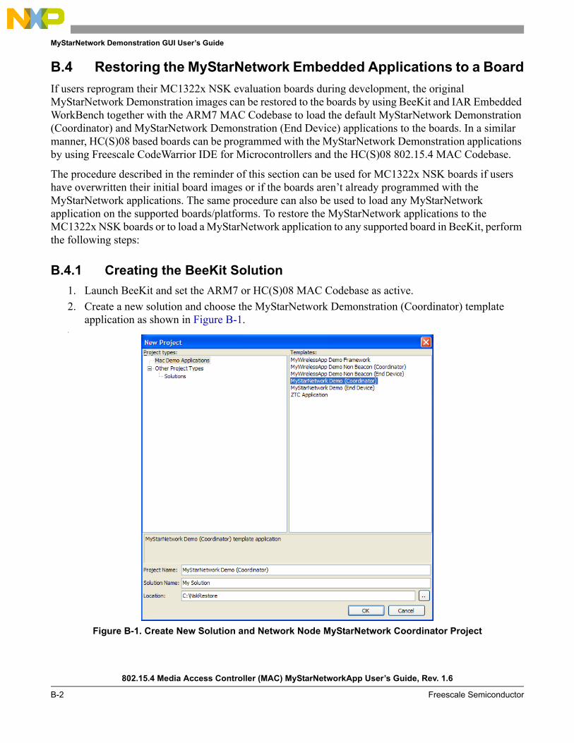
MyStarNetwork Demonstration GUI User’s Guide
802.15.4 Media Access Controller (MAC) MyStarNetworkApp User’s Guide, Rev. 1.6
B-2 Freescale Semiconductor
B.4 Restoring the MyStarNetwork Embedded Applications to a Board
If users reprogram their MC1322x NSK evaluation boards during development, the original MyStarNetwork Demonstration images can be restored to the boards by using BeeKit and IAR Embedded WorkBench together with the ARM7 MAC Codebase to load the default MyStarNetwork Demonstration (Coordinator) and MyStarNetwork Demonstration (End Device) applications to the boards. In a similar manner, HC(S)08 based boards can be programmed with the MyStarNetwork Demonstration applications by using Freescale CodeWarrior IDE for Microcontrollers and the HC(S)08 802.15.4 MAC Codebase.
The procedure described in the reminder of this section can be used for MC1322x NSK boards if users have overwritten their initial board images or if the boards aren’t already programmed with the MyStarNetwork applications. The same procedure can also be used to load any MyStarNetwork application on the supported boards/platforms. To restore the MyStarNetwork applications to the MC1322x NSK boards or to load a MyStarNetwork application to any supported board in BeeKit, perform the following steps:
B.4.1 Creating the BeeKit Solution
1. Launch BeeKit and set the ARM7 or HC(S)08 MAC Codebase as active.
2. Create a new solution and choose the MyStarNetwork Demonstration (Coordinator) template application as shown in Figure B-1.
3.
Figure B-1. Create New Solution and Network Node MyStarNetwork Coordinator Project
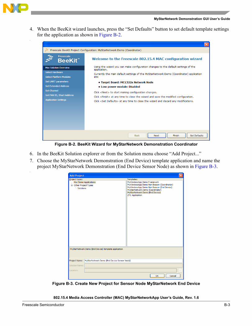
MyStarNetwork Demonstration GUI User’s Guide
802.15.4 Media Access Controller (MAC) MyStarNetworkApp User’s Guide, Rev. 1.6
Freescale Semiconductor B-3
4. When the BeeKit wizard launches, press the “Set Defaults” button to set default template settings for the application as shown in Figure B-2.
5.
Figure B-2. BeeKit Wizard for MyStarNetwork Demonstration Coordinator
6. In the BeeKit Solution explorer or from the Solution menu choose “Add Project...”
7. Choose the MyStarNetwork Demonstration (End Device) template application and name the project MyStarNetwork Demonstration (End Device Sensor Node) as shown in Figure B-3.
8.
Figure B-3. Create New Project for Sensor Node MyStarNetwork End Device
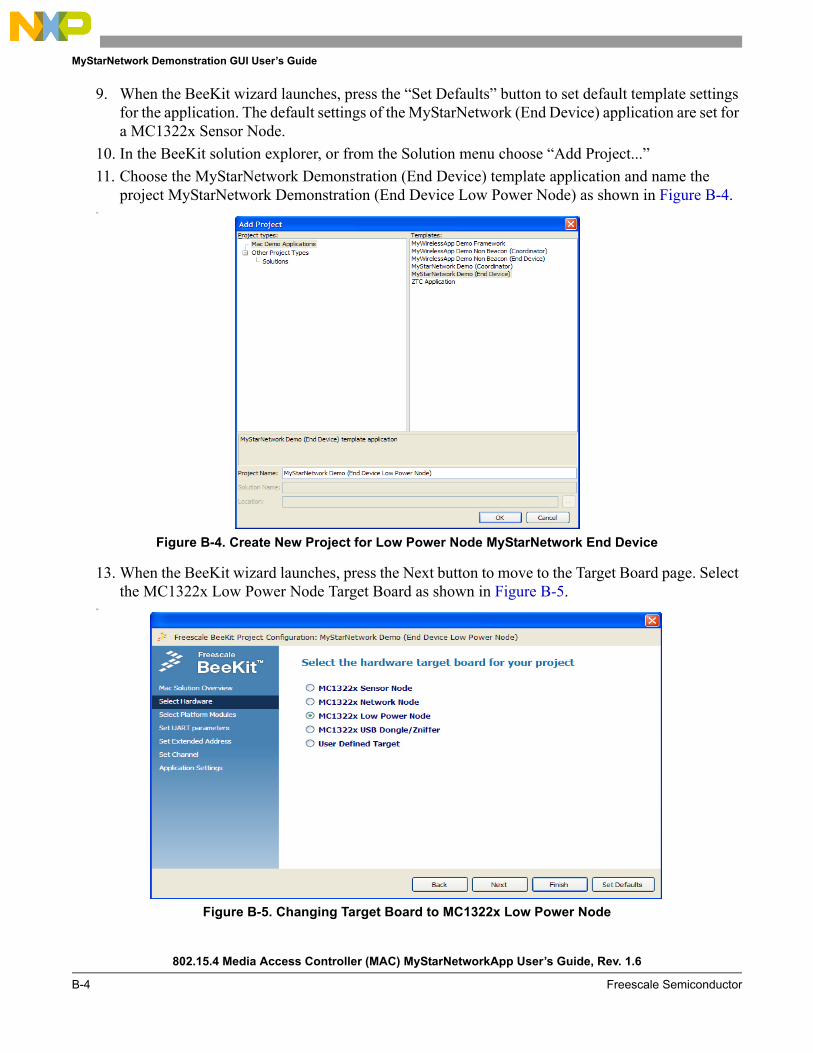
MyStarNetwork Demonstration GUI User’s Guide
802.15.4 Media Access Controller (MAC) MyStarNetworkApp User’s Guide, Rev. 1.6
B-4 Freescale Semiconductor
9. When the BeeKit wizard launches, press the “Set Defaults” button to set default template settings for the application. The default settings of the MyStarNetwork (End Device) application are set for a MC1322x Sensor Node.
10. In the BeeKit solution explorer, or from the Solution menu choose “Add Project...”
11. Choose the MyStarNetwork Demonstration (End Device) template application and name the project MyStarNetwork Demonstration (End Device Low Power Node) as shown in Figure B-4.
12.
Figure B-4. Create New Project for Low Power Node MyStarNetwork End Device
13. When the BeeKit wizard launches, press the Next button to move to the Target Board page. Select the MC1322x Low Power Node Target Board as shown in Figure B-5.
14.
Figure B-5. Changing Target Board to MC1322x Low Power Node
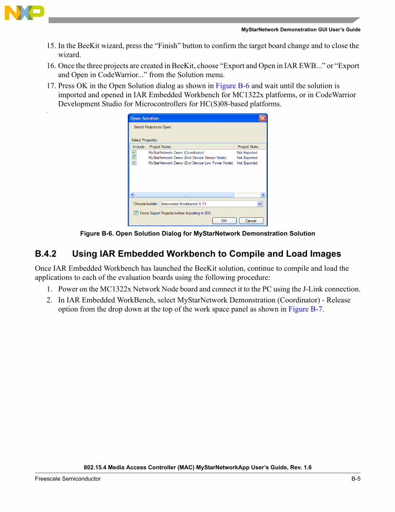
MyStarNetwork Demonstration GUI User’s Guide
802.15.4 Media Access Controller (MAC) MyStarNetworkApp User’s Guide, Rev. 1.6
Freescale Semiconductor B-5
15. In the BeeKit wizard, press the “Finish” button to confirm the target board change and to close the wizard.
16. Once the three projects are created in BeeKit, choose “Export and Open in IAR EWB...” or “Export and Open in CodeWarrior...” from the Solution menu.
17. Press OK in the Open Solution dialog as shown in Figure B-6 and wait until the solution is imported and opened in IAR Embedded Workbench for MC1322x platforms, or in CodeWarrior Development Studio for Microcontrollers for HC(S)08-based platforms.
18.
Figure B-6. Open Solution Dialog for MyStarNetwork Demonstration Solution
B.4.2 Using IAR Embedded Workbench to Compile and Load Images
Once IAR Embedded Workbench has launched the BeeKit solution, continue to compile and load the applications to each of the evaluation boards using the following procedure:
1. Power on the MC1322x Network Node board and connect it to the PC using the J-Link connection.
2. In IAR Embedded WorkBench, select MyStarNetwork Demonstration (Coordinator) - Release option from the drop down at the top of the work space panel as shown in Figure B-7.
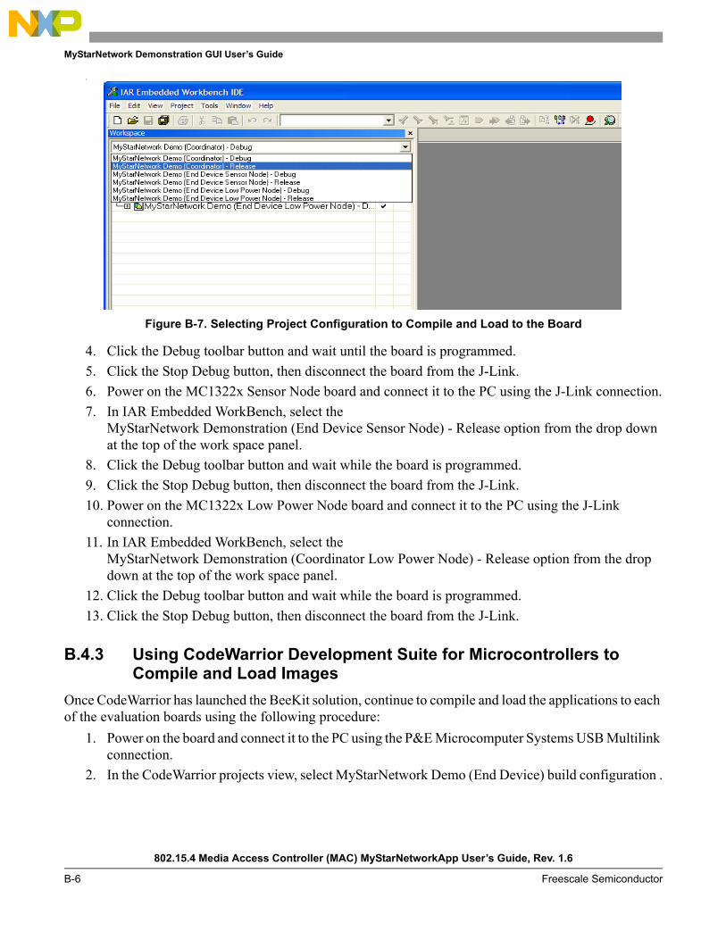
MyStarNetwork Demonstration GUI User’s Guide
802.15.4 Media Access Controller (MAC) MyStarNetworkApp User’s Guide, Rev. 1.6
B-6 Freescale Semiconductor
3.
Figure B-7. Selecting Project Configuration to Compile and Load to the Board
4. Click the Debug toolbar button and wait until the board is programmed.
5. Click the Stop Debug button, then disconnect the board from the J-Link.
6. Power on the MC1322x Sensor Node board and connect it to the PC using the J-Link connection.
7. In IAR Embedded WorkBench, select the MyStarNetwork Demonstration (End Device Sensor Node) - Release option from the drop down at the top of the work space panel.
8. Click the Debug toolbar button and wait while the board is programmed.
9. Click the Stop Debug button, then disconnect the board from the J-Link.
10. Power on the MC1322x Low Power Node board and connect it to the PC using the J-Link connection.
11. In IAR Embedded WorkBench, select the MyStarNetwork Demonstration (Coordinator Low Power Node) - Release option from the drop down at the top of the work space panel.
12. Click the Debug toolbar button and wait while the board is programmed.
13. Click the Stop Debug button, then disconnect the board from the J-Link.
B.4.3 Using CodeWarrior Development Suite for Microcontrollers to Compile and Load Images
Once CodeWarrior has launched the BeeKit solution, continue to compile and load the applications to each of the evaluation boards using the following procedure:
1. Power on the board and connect it to the PC using the P&E Microcomputer Systems USB Multilink connection.
2. In the CodeWarrior projects view, select MyStarNetwork Demo (End Device) build configuration .
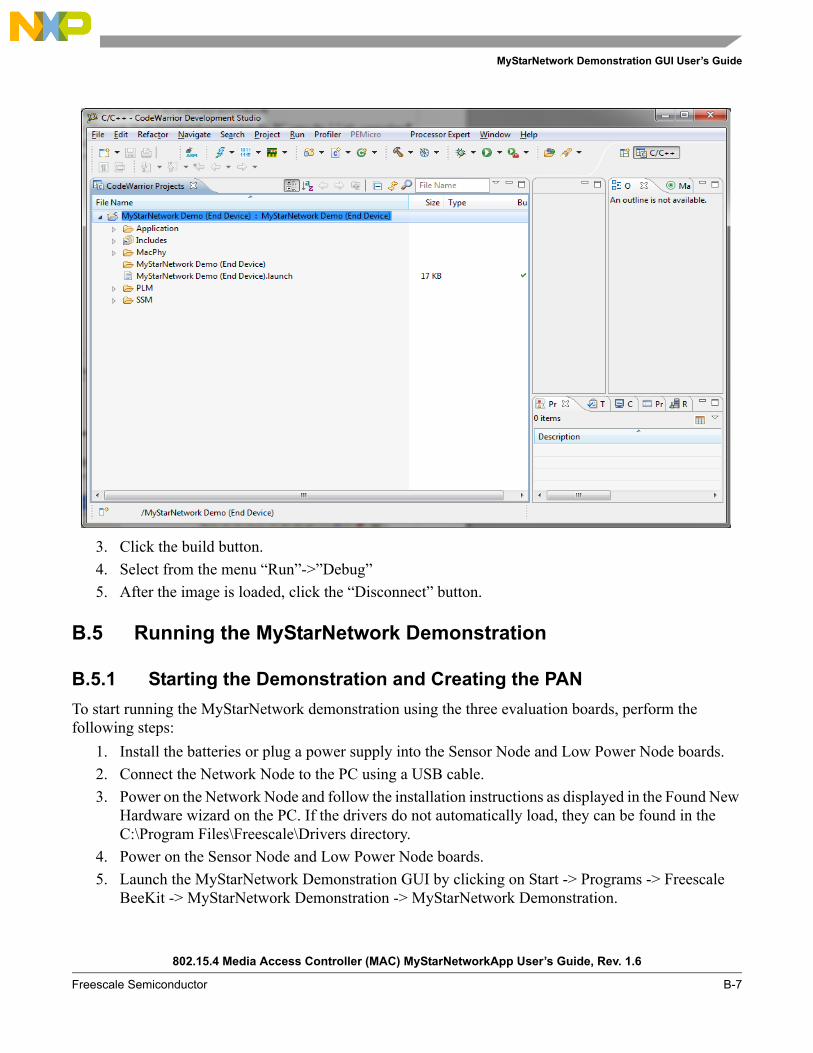
MyStarNetwork Demonstration GUI User’s Guide
802.15.4 Media Access Controller (MAC) MyStarNetworkApp User’s Guide, Rev. 1.6
Freescale Semiconductor B-7
3. Click the build button.
4. Select from the menu “Run”->”Debug”
5. After the image is loaded, click the “Disconnect” button.
B.5 Running the MyStarNetwork Demonstration
B.5.1 Starting the Demonstration and Creating the PAN
To start running the MyStarNetwork demonstration using the three evaluation boards, perform the following steps:
1. Install the batteries or plug a power supply into the Sensor Node and Low Power Node boards.
2. Connect the Network Node to the PC using a USB cable.
3. Power on the Network Node and follow the installation instructions as displayed in the Found New Hardware wizard on the PC. If the drivers do not automatically load, they can be found in the C:\Program Files\Freescale\Drivers directory.
4. Power on the Sensor Node and Low Power Node boards.
5. Launch the MyStarNetwork Demonstration GUI by clicking on Start -> Programs -> Freescale BeeKit -> MyStarNetwork Demonstration -> MyStarNetwork Demonstration.
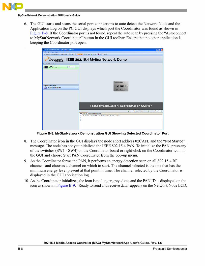
MyStarNetwork Demonstration GUI User’s Guide
802.15.4 Media Access Controller (MAC) MyStarNetworkApp User’s Guide, Rev. 1.6
B-8 Freescale Semiconductor
6. The GUI starts and scans the serial port connections to auto detect the Network Node and the Application Log on the PC GUI displays which port the Coordinator was found as shown in Figure B-8. If the Coordinator port is not found, repeat the auto scan by pressing the “Autoconnect to MyStarNetwork Coordinator” button in the GUI toolbar. Ensure that no other application is keeping the Coordinator port open.
7.
Figure B-8. MyStarNetwork Demonstration GUI Showing Detected Coordinator Port
8. The Coordinator icon in the GUI displays the node short address 0xCAFE and the “Not Started” message. The node has not yet initialized the IEEE 802.15.4 PAN. To initialize the PAN, press any of the switches (SW1 - SW4) on the Coordinator board or right-click on the Coordinator icon in the GUI and choose Start PAN Coordinator from the pop-up menu.
9. As the Coordinator forms the PAN, it performs an energy detection scan on all 802.15.4 RF channels and chooses a channel on which to start. The channel selected is the one that has the minimum energy level present at that point in time. The channel selected by the Coordinator is displayed in the GUI application log.
10. As the Coordinator initializes, the icon is no longer greyed out and the PAN ID is displayed on the icon as shown in Figure B-9. “Ready to send and receive data” appears on the Network Node LCD.
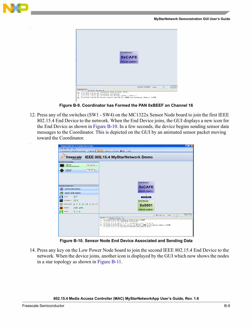
MyStarNetwork Demonstration GUI User’s Guide
802.15.4 Media Access Controller (MAC) MyStarNetworkApp User’s Guide, Rev. 1.6
Freescale Semiconductor B-9
11.
Figure B-9. Coordinator has Formed the PAN 0xBEEF on Channel 16
12. Press any of the switches (SW1 - SW4) on the MC1322x Sensor Node board to join the first IEEE 802.15.4 End Device to the network. When the End Device joins, the GUI displays a new icon for the End Device as shown in Figure B-10. In a few seconds, the device begins sending sensor data messages to the Coordinator. This is depicted on the GUI by an animated sensor packet moving toward the Coordinator.
13.
Figure B-10. Sensor Node End Device Associated and Sending Data
14. Press any key on the Low Power Node board to join the second IEEE 802.15.4 End Device to the network. When the device joins, another icon is displayed by the GUI which now shows the nodes in a star topology as shown in Figure B-11.
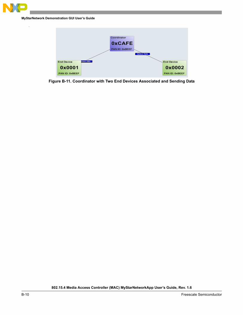
MyStarNetwork Demonstration GUI User’s Guide
802.15.4 Media Access Controller (MAC) MyStarNetworkApp User’s Guide, Rev. 1.6
B-10 Freescale Semiconductor
15.
Figure B-11. Coordinator with Two End Devices Associated and Sending Data
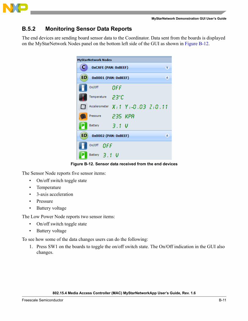
MyStarNetwork Demonstration GUI User’s Guide
802.15.4 Media Access Controller (MAC) MyStarNetworkApp User’s Guide, Rev. 1.6
Freescale Semiconductor B-11
B.5.2 Monitoring Sensor Data Reports
The end devices are sending board sensor data to the Coordinator. Data sent from the boards is displayed on the MyStarNetwork Nodes panel on the bottom left side of the GUI as shown in Figure B-12.
Figure B-12. Sensor data received from the end devices
The Sensor Node reports five sensor items:
• On/off switch toggle state
• Temperature
• 3-axis acceleration
• Pressure
• Battery voltage
The Low Power Node reports two sensor items:
• On/off switch toggle state
• Battery voltage
To see how some of the data changes users can do the following:
1. Press SW1 on the boards to toggle the on/off switch state. The On/Off indication in the GUI also changes.

MyStarNetwork Demonstration GUI User’s Guide
802.15.4 Media Access Controller (MAC) MyStarNetworkApp User’s Guide, Rev. 1.6
B-12 Freescale Semiconductor
2. Physically move the Sensor Node board and monitor the 3-axis changes in the GUI. The three values displayed are the acceleration values on 3 axis, indicating tilt in the range from -1g to 1g. For example, when the sensor node is placed horizontally on a flat surface, the X axis displays a value close to 1g while the Y and Z axis will be close to 0. Turn the board upside down and notice how the X axis changes to a value close to -1g.
3. Insert the hose and its attached pump to the pressure sensor connector on the Sensor Node. Use the pump to make changes to the pressure and monitor the changes in the GUI.
All association and sensor data information that the GUI displays is obtained from the Network Node which sends the packets it receives over the air from the end devices via the USB connection. To view the raw data packets sent through the USB from the Network Node, users can change to the “Coordinator Message Log” tab as shown in Figure B-13.
Figure B-13. Coordinator Message Log shows UART Communication with the Coordinator
At the end of the demonstration, users can reset or power off the end devices. After a 15 second timeout the devices are grayed out by the GUI and the status is set to inactive as shown in Figure B-14. After 15 more seconds, the devices are removed from the display.
Figure B-14. Inactive Disconnected Devices
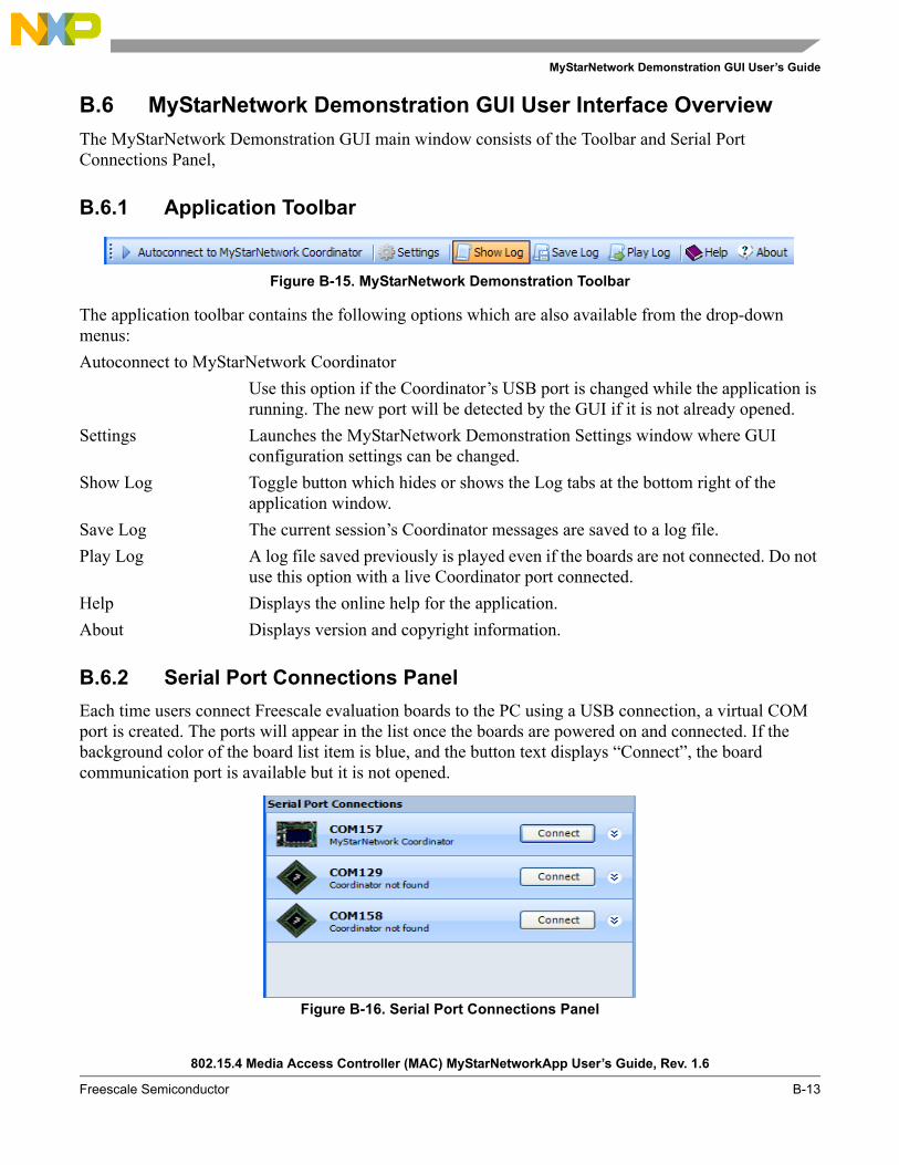
MyStarNetwork Demonstration GUI User’s Guide
802.15.4 Media Access Controller (MAC) MyStarNetworkApp User’s Guide, Rev. 1.6
Freescale Semiconductor B-13
B.6 MyStarNetwork Demonstration GUI User Interface Overview
The MyStarNetwork Demonstration GUI main window consists of the Toolbar and Serial Port Connections Panel,
B.6.1 Application Toolbar
Figure B-15. MyStarNetwork Demonstration Toolbar
The application toolbar contains the following options which are also available from the drop-down menus:
Autoconnect to MyStarNetwork Coordinator
Use this option if the Coordinator’s USB port is changed while the application is running. The new port will be detected by the GUI if it is not already opened.
Settings Launches the MyStarNetwork Demonstration Settings window where GUI configuration settings can be changed.
Show Log Toggle button which hides or shows the Log tabs at the bottom right of the application window.
Save Log The current session’s Coordinator messages are saved to a log file.
Play Log A log file saved previously is played even if the boards are not connected. Do not use this option with a live Coordinator port connected.
Help Displays the online help for the application.
About Displays version and copyright information.
B.6.2 Serial Port Connections Panel
Each time users connect Freescale evaluation boards to the PC using a USB connection, a virtual COM port is created. The ports will appear in the list once the boards are powered on and connected. If the background color of the board list item is blue, and the button text displays “Connect”, the board communication port is available but it is not opened.
Figure B-16. Serial Port Connections Panel
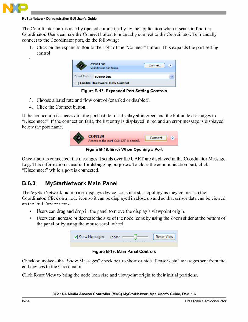
MyStarNetwork Demonstration GUI User’s Guide
802.15.4 Media Access Controller (MAC) MyStarNetworkApp User’s Guide, Rev. 1.6
B-14 Freescale Semiconductor
The Coordinator port is usually opened automatically by the application when it scans to find the Coordinator. Users can use the Connect button to manually connect to the Coordinator. To manually connect to the Coordinator port, do the following:
1. Click on the expand button to the right of the “Connect” button. This expands the port setting control.
2.
Figure B-17. Expanded Port Setting Controls
3. Choose a baud rate and flow control (enabled or disabled).
4. Click the Connect button.
If the connection is successful, the port list item is displayed in green and the button text changes to “Disconnect”. If the connection fails, the list entry is displayed in red and an error message is displayed below the port name.
Figure B-18. Error When Opening a Port
Once a port is connected, the messages it sends over the UART are displayed in the Coordinator Message Log. This information is useful for debugging purposes. To close the communication port, click “Disconnect” while a port is connected.
B.6.3 MyStarNetwork Main Panel
The MyStarNetwork main panel displays device icons in a star topology as they connect to the Coordinator. Click on a node icon so it can be displayed in close up and so that sensor data can be viewed on the End Device icons.
• Users can drag and drop in the panel to move the display’s viewpoint origin.
• Users can increase or decrease the size of the node icons by using the Zoom slider at the bottom of the panel or by using the mouse scroll wheel.
Figure B-19. Main Panel Controls
Check or uncheck the “Show Messages” check box to show or hide “Sensor data” messages sent from the end devices to the Coordinator.
Click Reset View to bring the node icon size and viewpoint origin to their initial positions.
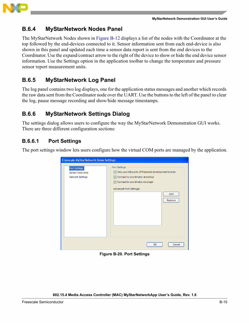
MyStarNetwork Demonstration GUI User’s Guide
802.15.4 Media Access Controller (MAC) MyStarNetworkApp User’s Guide, Rev. 1.6
Freescale Semiconductor B-15
B.6.4 MyStarNetwork Nodes Panel
The MyStarNetwork Nodes shown in Figure B-12 displays a list of the nodes with the Coordinator at the top followed by the end-devices connected to it. Sensor information sent from each end-device is also shown in this panel and updated each time a sensor data report is sent from the end devices to the Coordinator. Use the expand/contract arrow to the right of the device to show or hide the end device sensor information. Use the Settings option in the application toolbar to change the temperature and pressure sensor report measurement units.
B.6.5 MyStarNetwork Log Panel
The log panel contains two log displays, one for the application status messages and another which records the raw data sent from the Coordinator node over the UART. Use the buttons to the left of the panel to clear the log, pause message recording and show/hide message timestamps.
B.6.6 MyStarNetwork Settings Dialog
The settings dialog allows users to configure the way the MyStarNetwork Demonstration GUI works. There are three different configuration sections:
B.6.6.1 Port Settings
The port settings window lets users configure how the virtual COM ports are managed by the application.
Figure B-20. Port Settings
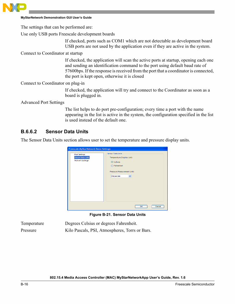
MyStarNetwork Demonstration GUI User’s Guide
802.15.4 Media Access Controller (MAC) MyStarNetworkApp User’s Guide, Rev. 1.6
B-16 Freescale Semiconductor
The settings that can be performed are:
Use only USB ports Freescale development boards
If checked, ports such as COM1 which are not detectable as development board USB ports are not used by the application even if they are active in the system.
Connect to Coordinator at startup
If checked, the application will scan the active ports at startup, opening each one and sending an identification command to the port using default baud rate of 57600bps. If the response is received from the port that a coordinator is connected, the port is kept open, otherwise it is closed
Connect to Coordinator on plug-in
If checked, the application will try and connect to the Coordinator as soon as a board is plugged in.
Advanced Port Settings
The list helps to do port pre-configuration; every time a port with the name appearing in the list is active in the system, the configuration specified in the list is used instead of the default one.
B.6.6.2 Sensor Data Units
The Sensor Data Units section allows user to set the temperature and pressure display units.
Figure B-21. Sensor Data Units
Temperature Degrees Celsius or degrees Fahrenheit.
Pressure Kilo Pascals, PSI, Atmospheres, Torrs or Bars.

MyStarNetwork Demonstration GUI User’s Guide
802.15.4 Media Access Controller (MAC) MyStarNetworkApp User’s Guide, Rev. 1.6
Freescale Semiconductor B-17
B.6.6.3 Network Settings
The network settings section lets user configure time-outs for end devices.
Figure B-22. Network Setting
No response End Device timeout
If no sensor report has been received from an End Device for this period, the End Device is grayed out and put in an inactive state
Remove End Device timeout
If no sensor report has been received from an End Device for this period, the End Device will be removed from the GUI.

MyStarNetwork Demonstration GUI User’s Guide
802.15.4 Media Access Controller (MAC) MyStarNetworkApp User’s Guide, Rev. 1.6
B-18 Freescale Semiconductor