802.11n Sniffer Vladislav Mordohovich Igor Shtarev.
39
802.11n Sniffer Vladislav Mordohovich Igor Shtarev
-
date post
21-Dec-2015 -
Category
Documents
-
view
232 -
download
0
Transcript of 802.11n Sniffer Vladislav Mordohovich Igor Shtarev.
802.11n Sniffer
Vladislav Mordohovich
Igor Shtarev
Foreword
802.11n is the new emerging WiFi Standard No suitable Sniffer is in production (as far
we know) This project’s aim is to create one - a
General description of it and technology basis of 802.11n are presented in the following slides
APPLICATION DETAILED
Features
Logging “real” 802.11n frames via Radwin driver LOCALLY/REMOTELY
Logging simulated 802.11n frames via “winpcap” REMOTELY (in WireShark format), including MSDU/MPDU aggregation simulation (both in send and receive)
Building topology of visible network, including distance simulation between visible stations
Features cont…
Clear and concise user interface – both for embedded platforms and for Windows
After each local sniffer is configured – all activity can be done from remote (start, stop, MSDU/MPDU aggregation trigger)
Apart from remote GUI module – application is OS independent and Real Time / embedded OS compatible ( main modules are coded in C++ with RT and efficiency considerations)
Features cont…(2)
Can be used as a basis for other applications in the field – contains “OS UTILS” package, including common OS functionality and implementation for Win32
All software modules are strictly separated and communicating via clear and concise API – allowing code reuse
OO designed and implemented
General Design Overview
Two main componentsSniffer ClientReports Server
The Client application resides on the machine with the physical 802.11n interface or “winpcap” interface, simulating 802.11n card.
The Reports Server can be installed on any host with IP access to the Client component (.net framework required for GUI, if used)
General Design Overview (2)
The Client and the Reports Server are communicating via the Syslog Protocol:Standard Event reporting protocolOver UDP
There is no limitation on number of Client stations, connected to single Report Server.
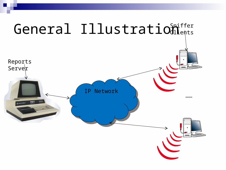
General Illustration Sniffer Clients
IP NetworkIP Network
Reports Server
……
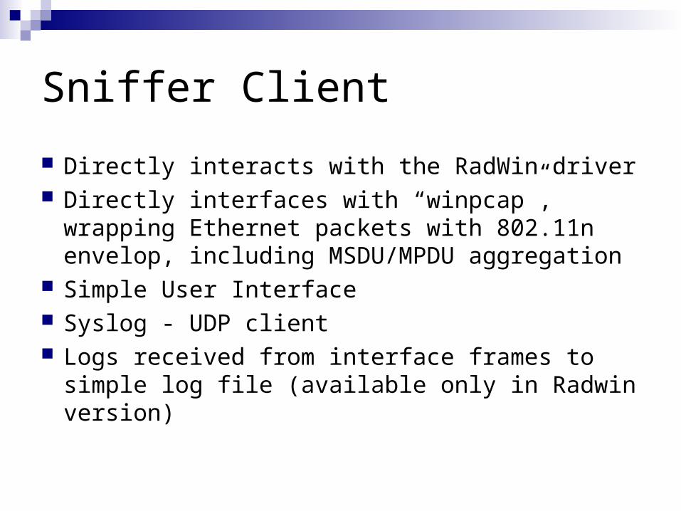
Sniffer Client
Directly interacts with the RadWin driver Directly interfaces with “winpcap”, wrapping
Ethernet packets with 802.11n envelop, including MSDU/MPDU aggregation
Simple User Interface Syslog - UDP client Logs received from interface frames to simple
log file (available only in Radwin version)
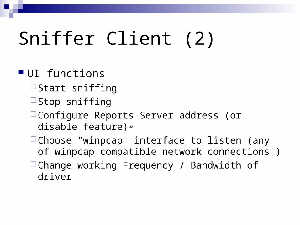
Sniffer Client (2)
UI functionsStart sniffingStop sniffingConfigure Reports Server address (or disable
feature)Choose “winpcap” interface to listen (any of
winpcap compatible network connections )Change working Frequency / Bandwidth of driver
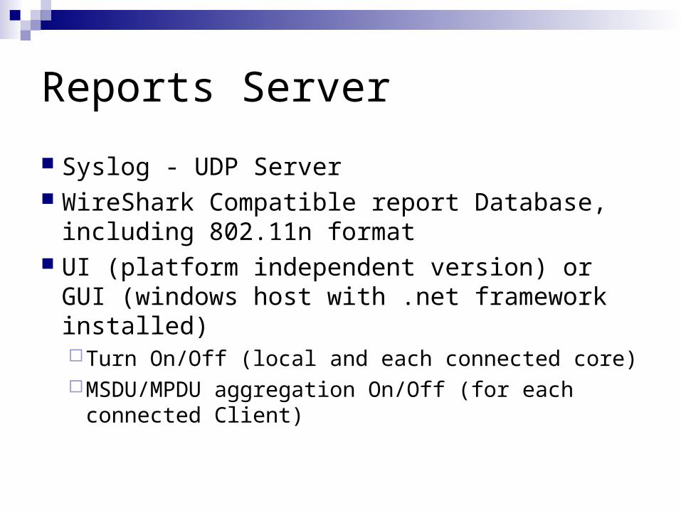
Reports Server
Syslog - UDP Server WireShark Compatible report Database,
including 802.11n format UI (platform independent version) or GUI
(windows host with .net framework installed)Turn On/Off (local and each connected core)MSDU/MPDU aggregation On/Off (for each
connected Client)
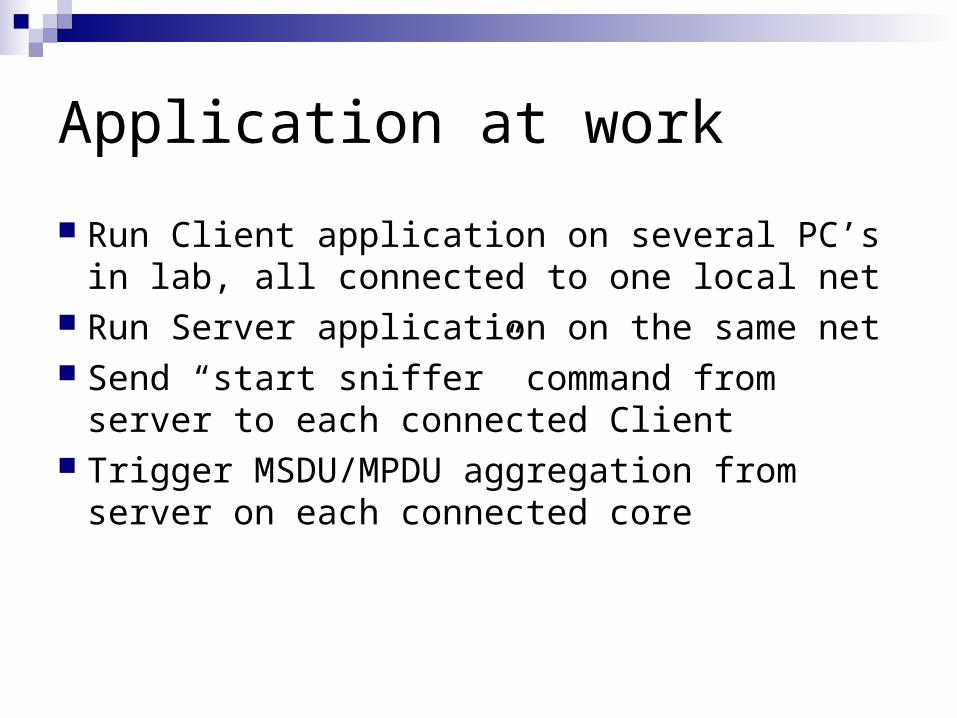
Application at work
Run Client application on several PC’s in lab, all connected to one local net
Run Server application on the same net Send “start sniffer” command from server
to each connected Client Trigger MSDU/MPDU aggregation from
server on each connected core
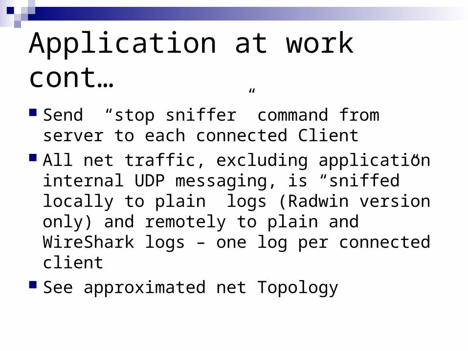
Application at work cont…
Send “stop sniffer” command from server to each connected Client
All net traffic, excluding application internal UDP messaging, is “sniffed” locally to plain logs (Radwin version only) and remotely to plain and WireShark logs – one log per connected client
See approximated net Topology
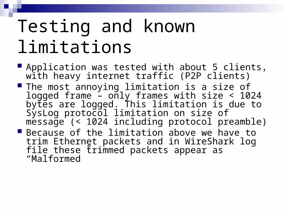
Testing and known limitations
Application was tested with about 5 clients, with heavy internet traffic (P2P clients)
The most annoying limitation is a size of logged frame – only frames with size < 1024 bytes are logged. This limitation is due to SysLog protocol limitation on size of message (< 1024 including protocol preamble)
Because of the limitation above we have to trim Ethernet packets and in WireShark log file these trimmed packets appear as “Malformed”
THEORETICAL PART(based on James M. Wilson - Intel,
“Quadrupling Wi-Fi speeds with 802.11n”)
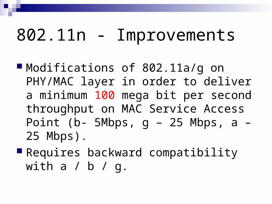
802.11n - Improvements
Modifications of 802.11a/g on PHY/MAC layer in order to deliver a minimum 100 mega bit per second throughput on MAC Service Access Point (b- 5Mbps, g – 25 Mbps, a – 25 Mbps).
Requires backward compatibility with a / b / g.
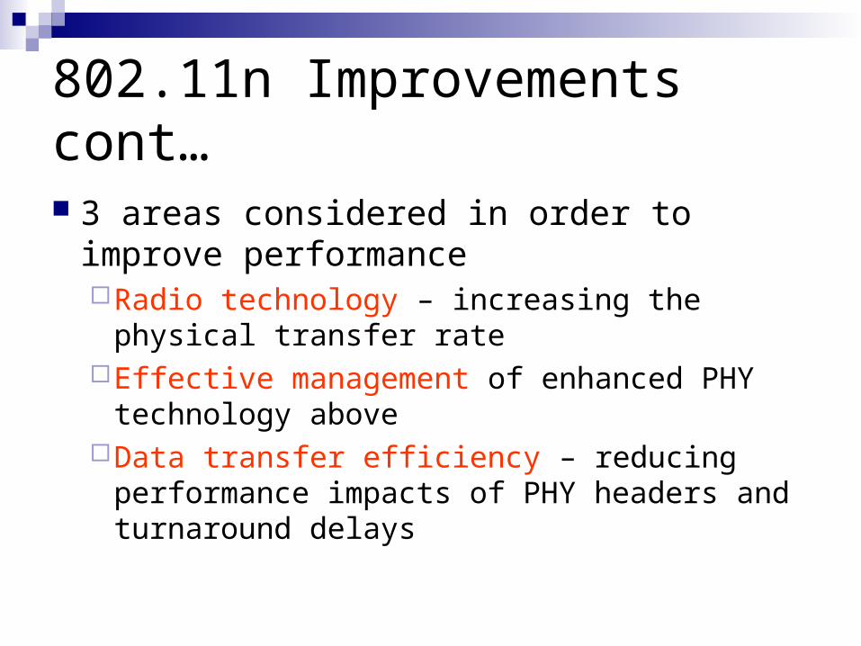
802.11n Improvements cont…
3 areas considered in order to improve performance Radio technology – increasing the physical
transfer rateEffective management of enhanced PHY
technology aboveData transfer efficiency – reducing performance
impacts of PHY headers and turnaround delays
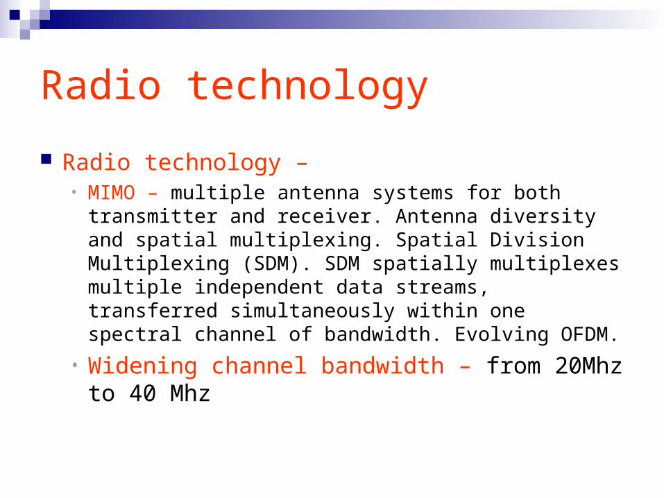
Radio technology
Radio technology – • MIMO – multiple antenna systems for both transmitter
and receiver. Antenna diversity and spatial multiplexing. Spatial Division Multiplexing (SDM). SDM spatially multiplexes multiple independent data streams, transferred simultaneously within one spectral channel of bandwidth. Evolving OFDM.
• Widening channel bandwidth – from 20Mhz to 40 Mhz
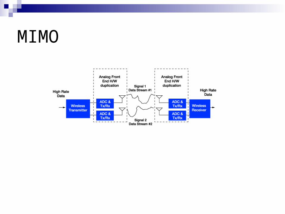
MIMO
Effective management of PHY
MAC layer should establish and maintain adaptation to wireless channel conditions Selection of modulation coding schemesAntenna configurationsChannel bandwidthsMIMO channel selection
Data transfer efficiency
MAC SAP layer improvements. PHY header significantly limits achievable
throughput . PHY headers need to be longer to support
the new advanced PHY Layer modes described earlier.
Data transfer efficiency (2)
Introducing new aggregate exchange sequencesmultiple MAC protocol data units (MPDU’s) are
aggregated into a single PPDU (PHY protocol data unit)
Block ACK – single ACK for multiple MPDU’s in response to BAR (block ACK request)
Require longer PPDU’s than previous standarts allow (> 4095 bytes)
AGGREGATION DETAILED(based on several internet
sources)
Frame AggregationScope of 802.11n An extension of the existing 802.11
framework The allowed changes are enhancements No existing functionality is subtracted Only those existing mechanisms that
pertain in some way to higher throughput are altered
Frame AggregationRationale(Effects of PHY data rate improvements)
The 802.11n amendment calls for rates of at least 100 MBPs, as measured at the interface between the 802.11 media-access control (MAC) and higher layers
The motivation is that the net data rate experienced by the user in wireless LANs is significantly affected by the many sources of overhead within the 802.11 protocol
The overhead comes primarily from packet preambles, acknowledgements, contention windows and various interframe-spacing parameters
Frame AggregationRationale (2)
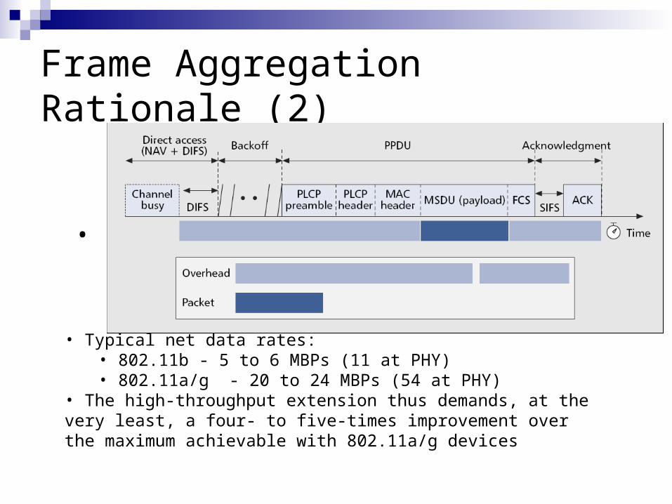
•
• Typical net data rates: • 802.11b - 5 to 6 MBPs (11 at PHY)• 802.11a/g - 20 to 24 MBPs (54 at PHY)
• The high-throughput extension thus demands, at the very least, a four- to five-times improvement over the maximum achievable with 802.11a/g devices
Frame AggregationIntroduction
• Thus, since the overhead remains rather fixed, no improvements in PHY data rate can compensate for low throughput at the MAC level• To solve this issue the 802.1n amendment proposes MAC enhancements to maximize throughput and efficiency• The most important of these are the two Frame Aggregation mechanisms:
• MAC Service Data Unit (MSDU) Aggregation• MAC Protocol Data Unit (MPDU) Aggregation
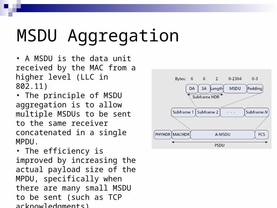
MSDU Aggregation• A MSDU is the data unit received by the MAC from a higher level (LLC in 802.11)• The principle of MSDU aggregation is to allow multiple MSDUs to be sent to the same receiver concatenated in a single MPDU.• The efficiency is improved by increasing the actual payload size of the MPDU, specifically when there are many small MSDU to be sent (such as TCP acknowledgments)• Only one PHY header and one MAC header for multiple frames
MSDU Aggregation (2)
For an A-MSDU (Aggregated MSDU) to be formed, a layer at the top of the MAC receives and buffers multiple packets (MSDUs)
The A-MSDU is completed either when the size of the waiting packets reaches the maximal A-MSDU threshold or the maximal delay of the oldest packet reaches a pre-assigned value
MSDU Aggregation (3)
Since the aggregation is performed at the top of the MAC, and since there’s one MAC header for all sub frames, the following constrictions are applied: All MSDUs must have the same TID value (QOS identifier within
the MAC data service) The destination address (DA) and sender address (SA)
parameter values in the subframe header must match to the same receiver address (RA) and transmitter address (TA) in the MAC header The destination address (DA) and sender
The maximal A-MSDU size is 8K A major drawback in using A-MSDU is under error-prone
channels – by compressing multiple MSDUs into a single MPDU with a single sequence number, for any subframe that is corrupted, the entire A-MSDU must be retransmitted.
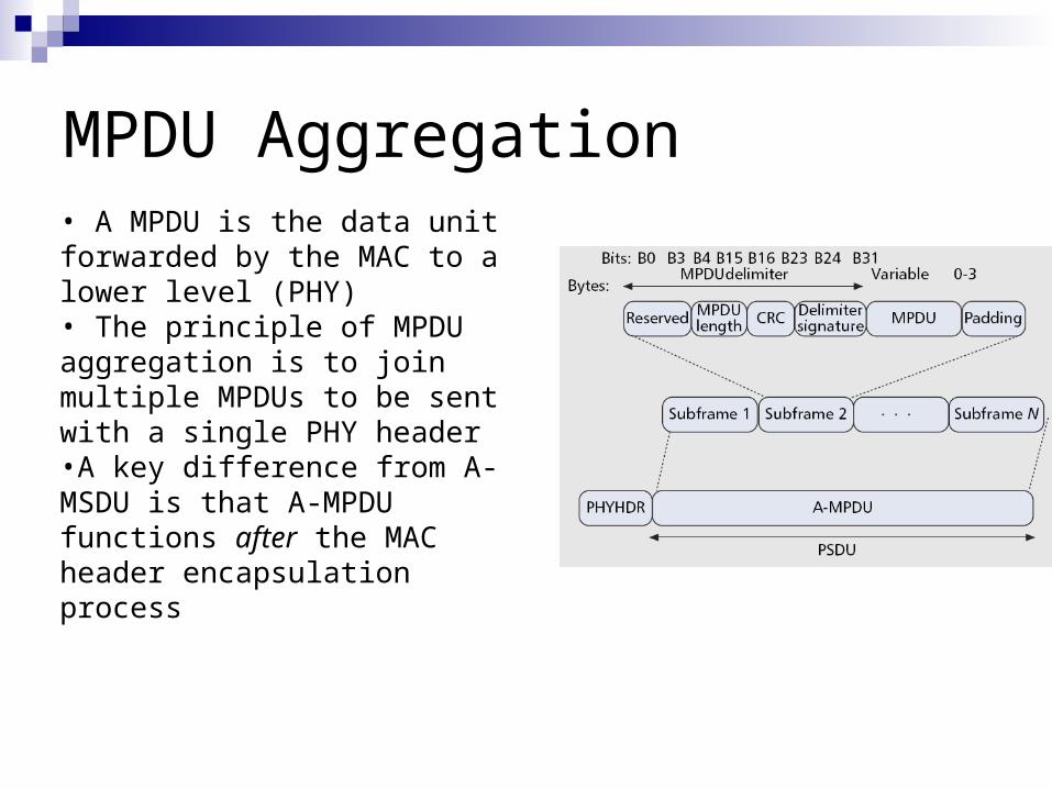
MPDU Aggregation• A MPDU is the data unit forwarded by the MAC to a lower level (PHY)• The principle of MPDU aggregation is to join multiple MPDUs to be sent with a single PHY header•A key difference from A-MSDU is that A-MPDU functions after the MAC header encapsulation process
MPDU Aggregation (2)
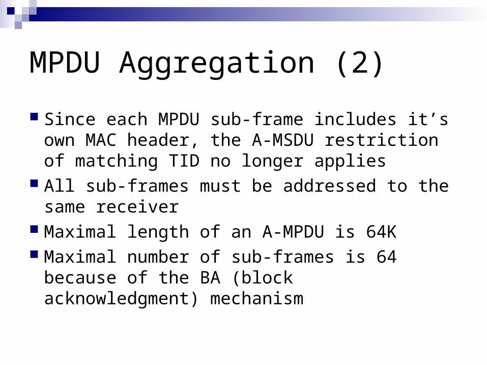
Since each MPDU sub-frame includes it’s own MAC header, the A-MSDU restriction of matching TID no longer applies
All sub-frames must be addressed to the same receiver
Maximal length of an A-MPDU is 64K Maximal number of sub-frames is 64 because
of the BA (block acknowledgment) mechanism
MPDU Aggregation (3)
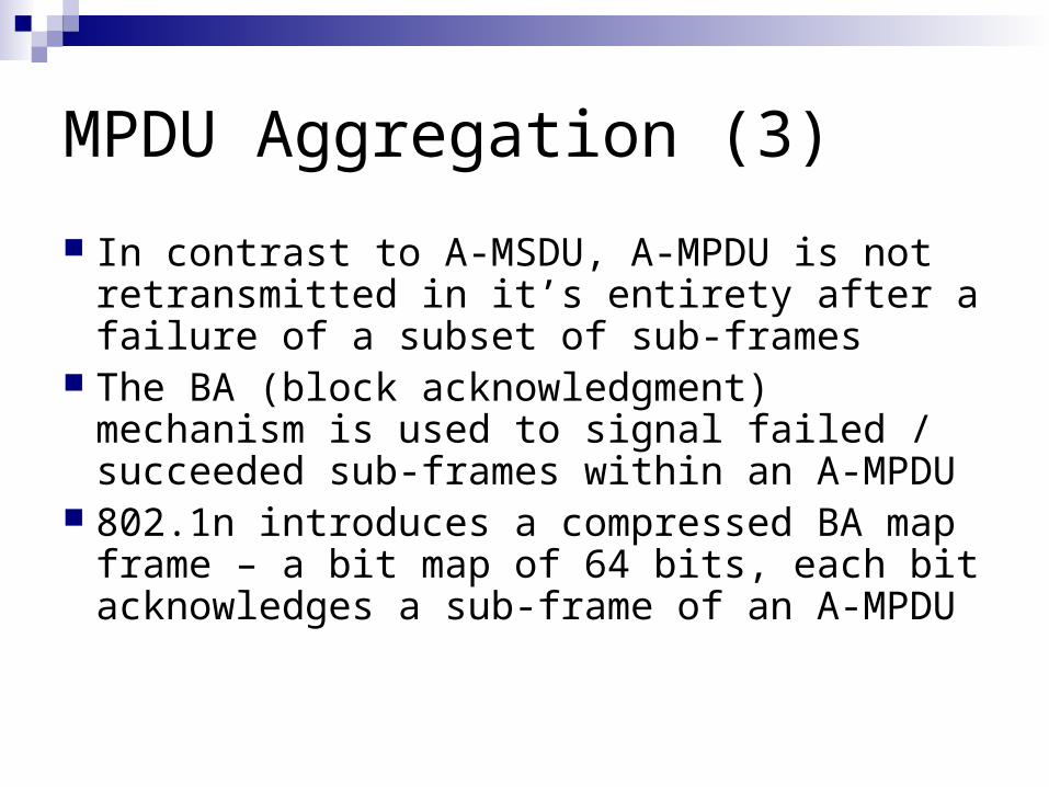
In contrast to A-MSDU, A-MPDU is not retransmitted in it’s entirety after a failure of a subset of sub-frames
The BA (block acknowledgment) mechanism is used to signal failed / succeeded sub-frames within an A-MPDU
802.1n introduces a compressed BA map frame – a bit map of 64 bits, each bit acknowledges a sub-frame of an A-MPDU
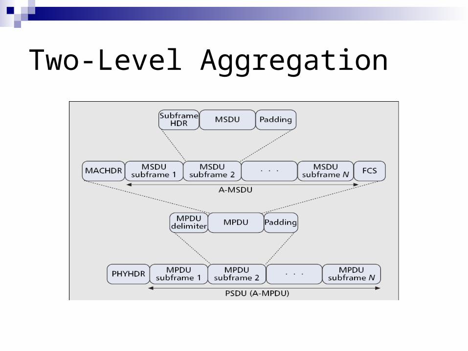
Two-Level Aggregation
Example
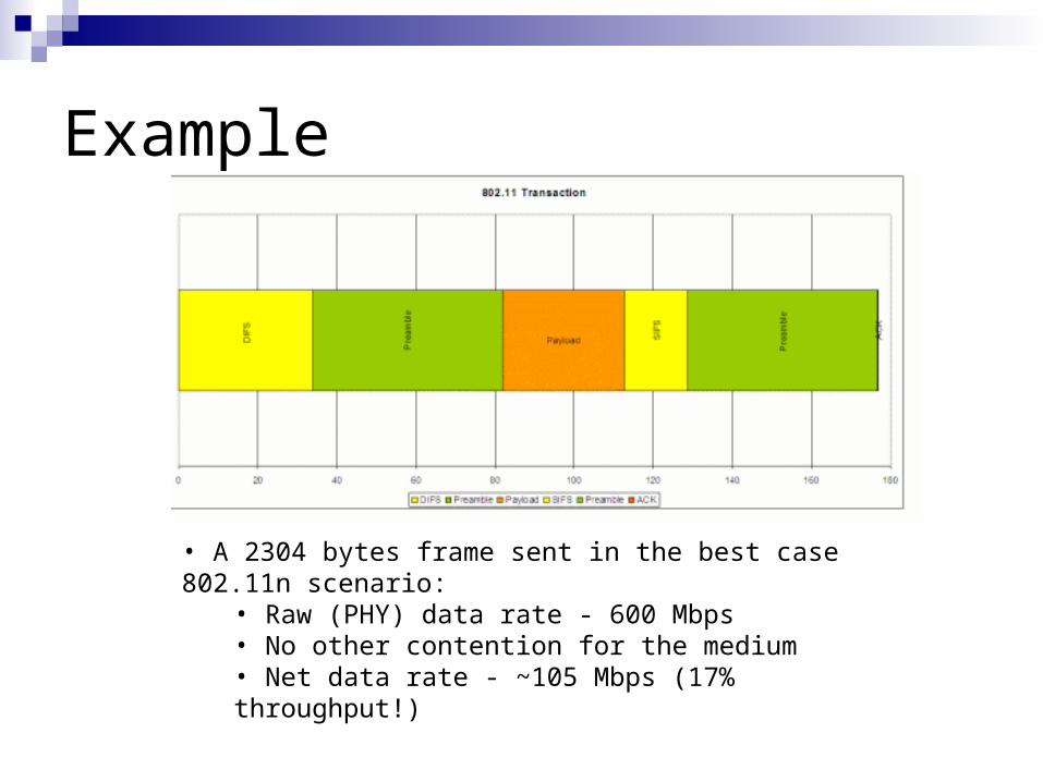
• A 2304 bytes frame sent in the best case 802.11n scenario: • Raw (PHY) data rate - 600 Mbps• No other contention for the medium• Net data rate - ~105 Mbps (17% throughput!)
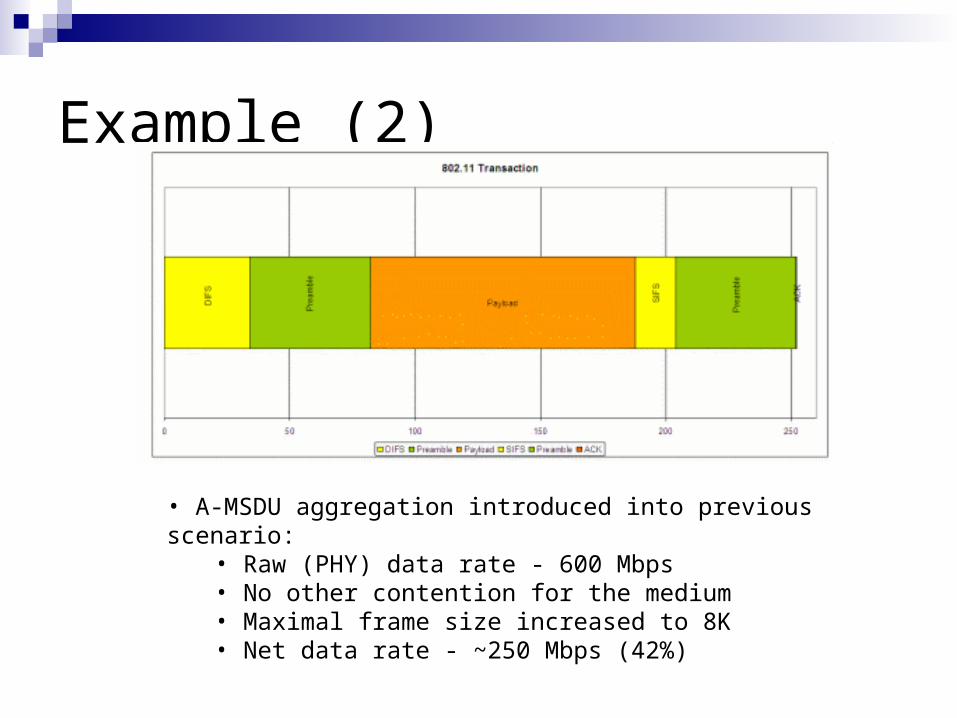
Example (2)
• A-MSDU aggregation introduced into previous scenario: • Raw (PHY) data rate - 600 Mbps• No other contention for the medium• Maximal frame size increased to 8K• Net data rate - ~250 Mbps (42%)
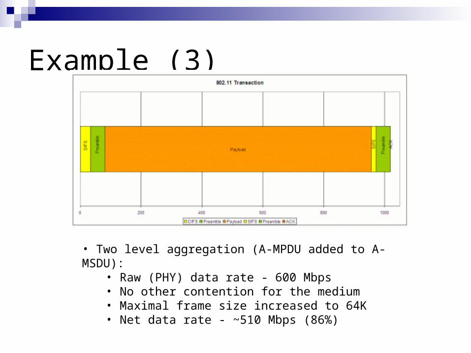
Example (3)
• Two level aggregation (A-MPDU added to A-MSDU): • Raw (PHY) data rate - 600 Mbps• No other contention for the medium• Maximal frame size increased to 64K• Net data rate - ~510 Mbps (86%)
Frame AggregationSimulation in the Project
• MSDU•Each A-MSDU is generated with random number of sub-frames. Configured in code.•Several captured Ethernet Packets are buffered until the A-MSDU is filled.
•MPDU•As with A-MSDU, A-MPDU’s sub-frames number is randomly generated.•Each sub-frame is sent without being buffered.•A sub-frame includes meta-information
•Is a MPDU is part of aggregation•Is a MPDU is the last in aggregation